

Page 1

User's Guide
SLUU446A–June 2011–Revised September 2011
EV2400 EVM Interface Board
This user's guide describes the function and operation of the EV2400 evaluation module interface board.
A complete description, as well as the bill of materials and schematic are included.
Contents
1 Introduction .................................................................................................................. 2
2 Interfaces ..................................................................................................................... 2
3 EV2400 Bill of Materials, Component Placement, Schematic ........................................................ 5
List of Figures
1 EV2400 Ports................................................................................................................ 3
2 Top Assembly ............................................................................................................... 8
3 Bottom Assembly ........................................................................................................... 9
4 Board Layer 1.............................................................................................................. 10
5 Board Layer 2.............................................................................................................. 11
6 Solder Mask 1.............................................................................................................. 12
7 Solder Mask 2.............................................................................................................. 13
8 Silkscreen................................................................................................................... 14
9 Schematic, Page 1 ........................................................................................................ 15
10 Schematic, Page 2 ........................................................................................................ 16
11 Schematic, Page 3 ........................................................................................................ 17
List of Tables
1 Ordering Information........................................................................................................ 2
SLUU446A–June 2011– Revised September 2011 EV2400 EVM Interface Board
Submit Documentation Feedback
Copyright © 2011, Texas Instruments Incorporated
1
Page 2

Introduction
1 Introduction
The EV2400 EVM interface board enables an IBM-compatible or other type PC (with the required driver
for its particular platform) to communicate with the Texas Instruments SMBus, I2C, HDQ, or DQ interface
gas gauges via a Universal Serial Bus (USB) port. In addition to this board, PC software is required to
interpret the gas gauge data to complete the evaluation system.
1.1 Features
• Fully powered from the USB port
• Optional 5-V port for powering high power voltage drivers (future upgrade)
• Complete interface between the USB and SMBus, I2C, and HDQ (8/16) interfaces using a simple API
• Expansion port for future upgrades
1.2 Kit Contents
• EV2400 circuit module
• Standard USB cable
1.3 Ordering Information
www.ti.com
Table 1. Ordering Information
EVM Part Number
EV2400
2 Interfaces
The EV2400 interfaces are described in the following table. The reference designators on the circuit board
and the functions are also listed.
Reference Designator Function Details
Port 1: SMB SMBus Interface Port
Port 2: I2C I2C Interface Port
Port 3: HDQ HDQ and DQ Interface Ports
Port 4 Single Wire Port Future expansion port
Port 5 GPIO Port Future expansion port
Terminal block for connecting to a target
device
Terminal block for connecting to a target
device
Terminal block for connecting to a target
device
2
EV2400 EVM Interface Board SLUU446A–June 2011– Revised September 2011
Copyright © 2011, Texas Instruments Incorporated
Submit Documentation Feedback
Page 3

www.ti.com
2.1 Overview
The EV2400 ports are shown in Figure 1.
NOTE: The additional power input 5-V port on the EV2400 must not be connected in normal
Interfaces
Figure 1. EV2400 Ports
operation. Normal operation uses power from the USB port.
2.2 EV2400 Controller
The EV2400 controller is an MSP430F5529 running at 4 MHz. The controller firmware is stored in flash
memory and is executed by the core at power-up.
The controller communicates with target device(s) through either: a 2-wire SMBus communication port, a
1-wire HDQ port, or a 2-wire EEPROM I2C port. The 2-wire SMBus communication port supports both
SMBus and I2C protocols. CRC-8 checksum verification for the data packets prevents data corruption over
the USB.
2.3 USB Interface (USB)
The interface board connects to a USB port (version 1.1 or later) on a host computer and is powered from
the port. All communication over the USB is human Interface device (HID) class. Drivers are built into
Windows®and most of the operating systems.
2.4 HDQ Interface (HDQ)
This interface allows a host computer to interact with a slave or target device through the 1-wire HDQ
interface. The ports are labeled with the corresponding signal names above each port connector. Connect
the signal and a ground reference (VSS) to a target device.
Pin Name Description
3.1 VSS Ground return/reference for HDQ interface.
3.2 VOUT 3 Optional voltage output (future expansion)
3.3 SDA HDQ 1-wire interface. Pulled up to variable pullup voltage with a 20-kΩ
3.4 VOUT 4 Optional voltage output (future expansion)
resistor. Uses bus acceleration in positive direction to allow for larger
pullup.
SLUU446A–June 2011– Revised September 2011 EV2400 EVM Interface Board
Submit Documentation Feedback
Copyright © 2011, Texas Instruments Incorporated
3
Page 4

Interfaces
2.5 I2C Interface (I2C)
This interface allows a host computer to interact with I2C interfaces, such as a battery monitor device and
EEPROM through a 2-wire I2C interface. Connect the data, clock, and a ground reference (VSS) to a
target device.
Pin Name Description
2.1 VSS Ground return/reference for I2C interface.
2.2 SCL I2C clock. Uses level translation. Pulled up to variable pullup voltage with a
2.3 SDA I2C data. Uses level translation. Pulled up to variable pullup voltage with a
2.4 VOUT 2 Optional voltage output (future expansion)
2.6 SMBus Interface (SMBus)
This interface allows a host computer to interact with an SMBus interface device such as a battery monitor
device through a 2-wire SMBus interface. Connect the data, clock, and a ground reference (VSS) to a
target device.
Pin Name Description
1.1 VSS Ground return/reference for SMBus
1.2 SCL SMBus clock. Pulled up to variable pullup
1.3 SDA SMBus data. Pulled up to variable pullup
1.4 VOUT 1 Optional voltage output (future expansion)
www.ti.com
20-kΩ resistor. Uses bus acceleration in positive direction to allow for
larger pullup.
20-kΩ resistor. Uses bus acceleration in positive direction to allow for
larger pullup.
interface.
voltage with a 20-kΩ resistor. Uses bus
acceleration in positive direction to allow
for larger pullup.
voltage with a 20-kΩ resistor. Uses bus
acceleration in positive direction to allow
for larger pullup.
4
EV2400 EVM Interface Board SLUU446A–June 2011– Revised September 2011
Copyright © 2011, Texas Instruments Incorporated
Submit Documentation Feedback
Page 5

www.ti.com
EV2400 Bill of Materials, Component Placement, Schematic
3 EV2400 Bill of Materials, Component Placement, Schematic
This chapter includes the bill of materials, component placement on the circuit board, and schematic for
the EV2400 EVM.
3.1 Bill of Materials (BOM)
Count Reference Design Value Description Size Part Number Manufacturer
31 C1, C2, C3, C4, 0.1 µF Capacitor, 0603 STD Any
1 C12 4.7 µF Capacitor, 0805 STD Any
1 C36 2.2 nF Capacitor, 0603 STD Any
2 C37, C41 220 pF Capacitor, 0603 STD Any
1 C40 470 nF Capacitor, 0603 STD Any
2 C42, C43 12 pF Capacitor, 0603 STD Any
2 C8, C10 2.2 µF Capacitor, 0603 STD Any
3 C9, C14, C17 10 µF Capacitor, 3216 293D106X0010A Vishay
6 D1, D2, D3, D4, GL05T Diode, TVS SOT23 GL05T General
3 D7, D8, D9 SSF-LXH305GD- Diode. LED, 2.6 0.250 x0.250 SSF- Lumex
1 J1 67068-1000 Connector, USB 0.47 x 0.67 inch 67068-1000 Molex
4 J2, J3, J4, J5 22-05-3041 Header, Friction 0.400 x 0.500 22-05-3041 Molex
1 J6 PEC12DBAN Header, Right 0.100 inch x 12 PEC12DBAN Sullins
1 J7 RAPC 722 Connector, 0.57 x 0.35 inch RAPC 722 Switchcraft
1 J8 22-23-2041 Header, 4-pin 0.250 x 0.400 22-23-2041 Molex
0 JP1, JP2, JP3, DNP Header, 2-pin, 0.100 inch x 2 PEC02SAAN Sullins
C5, C6, C7, C11, Ceramic, 25 V,
C13, C15, C16, X7R, 20%
C18, C19, C20,
C21, C22, C23,
C24, C25, C26,
C27, C28, C29,
C30, C31, C32,
C33, C34, C35,
C38, C39
Ceramic, 25 V,
X7R, 20%
Ceramic, 25 V,
X7R, 20%
Ceramic, 50 V,
C0G, 5%
Ceramic, 25 V,
X7R, 20%
Ceramic, 50 V,
C0G, 10%
Ceramic, 25 V,
X7R, 20%
Tantalum, 10 µF, 2T
10 V, 20%
D5, D6 diode, Low
Capacitance
TR V, 25 mA inch LXH305GD-TR
Upstream (Type
B)
Lock Ass'y, 4-pin inch
Right Angle,
Angle, Male x 2
2x12-pin, 100mil
spacing (12-pin
strip), right-angle
2.1mm, DC Jack
w/Switch, TH
Friction Lock, inch
100-mil spacing
JP4, JP5, JP6 100-mil spacing
SLUU446A–June 2011– Revised September 2011 EV2400 EVM Interface Board
Submit Documentation Feedback
Copyright © 2011, Texas Instruments Incorporated
5
Page 6

EV2400 Bill of Materials, Component Placement, Schematic
Count Reference Design Value Description Size Part Number Manufacturer
1 JP7 PEC02SAAN Header, 2-pin, 0.100 inch x 2 PEC02SAAN Sullins
6 Q1, Q2, Q3, Q4, BSS223PW MOSFET, Pch, SOT323 BSS223PW Infineon
Q5, Q6 –20 V, –0.39 A,
3 Q7, Q8, Q9 2N7002W MOSFET, Nch, SOT323 [SC70] 2N7002W Diodes
1 R1 33 kΩ Resistor, Chip, 0603 STD Any
4 R10, R11, R13, 20 kΩ Resistor, Chip, 0603 STD Any
R14 1/16 W, 5%
2 R2, R3 33 Ω Resistor, Chip, 0603 STD Any
1 R26 470 Ω Resistor, Chip, 0603 STD Any
1 R27 51 kΩ Resistor, Chip, 0603 STD Any
1 R28 100 kΩ Resistor, Chip, 0603 STD Any
3 R39, R40, R41 200 Ω Resistor, Chip, 0603 STD Any
1 R4 1.5 kΩ Resistor, Chip, 0603 STD Any
1 R42 47 kΩ Resistor, Chip, 0603 STD Any
3 R43, R44, R45 10 kΩ Resistor, Chip, 0603 STD Any
3 R46, R47, R48 100 kΩ Resistor, Chip, 0603 STD Any
21 R5, R6, R7, R12, 10 kΩ Resistor, Chip, 0603 STD Any
R15, R16, R19, 1/16 W, 5%
R20, R22, R24,
R25, R29, R30,
R31, R32, R33,
R34, R35, R36,
R37, R38
6 R8, R9, R17, R18, 100 Ω Resistor, Chip, 0603 STD Any
R21, R23 1/16 W, 5%
1 SW1 EVQPSD02K Switch, SMD 6.1 mm x 4.0 EVQPSD02K Panasonic
1 TP1 5VUSB Test Point, Red, 0.100 x 0.100 5000 Keystone
1 TP2 5VPLUG Test Point, Red, 0.100 x 0.100 5000 Keystone
1 TP3 3.3V Test Point, Red, 0.100 x 0.100 5000 Keystone
1 TP4 GND Test Point, 0.100 x 0.100 5001 Keystone
1 U1 MSP430F5529IP IC, Mixed Signal TQFP-80 MSP430F5529IP TI
N Microcontroller N
6 U10, U11, U12, TPS73601DBV IC, Cap-Free, SOT23-5 TPS73601DBV TI
U13, U15, U18 NMOS, 400mA
www.ti.com
100-mil spacing
1.2 Ohm
60 V, 115 mA
1/16 W, 5%
1/16 W, 5%
1/16 W, 1%
1/16 W, 1%
1/10 W, 1%
1/16 W, 5%
1/16 W, 5%
1/16 W, 5%
1/10 W, 1%
1/16 W, 5%
Light-Touch, mm
Side Operation
Thru Hole Color inch
Keyed
Thru Hole Color inch
Keyed
Thru Hole Color inch
Keyed
Black, Thru Hole inch
Color Keyed
LDO Regulator
with Reverse
Current
Protection.
6
EV2400 EVM Interface Board SLUU446A–June 2011– Revised September 2011
Copyright © 2011, Texas Instruments Incorporated
Submit Documentation Feedback
Page 7

www.ti.com
EV2400 Bill of Materials, Component Placement, Schematic
Count Reference Design Value Description Size Part Number Manufacturer
1 U2 TPS2550DBV IC, SOT-23-6 TPS2550DBV TI
PowerDistribution
Switch,
Current-Limited
1 U3 TPS76333DBV IC, Micro-Power SOT23-5 TPS76333DBV TI
150-mA LDO
Regulator
3 U4, U5, U6 ST2329AQTR IC, 2-bit dual 10-QFN ST2329AQTR ST
supply level
translator
without direction
control pin
1 U7 TPS79650DCQ IC, SOT223-6 TPS79650DCQ TI
Ultralow-Noise,
High PSRR Fast
RF, LDO, 1A, 5V
1 U8 TPS2113APW IC, Auto SO8 TPS2113APW TI
Switching Power
Mux, Rds 84
milli Ohm, 1A.
2 U9, U14 ISL90842UIV1427 IC, Quad TSSOP ISL90842UIV142 Intersil
Z Digitally 7Z
Controlled
Potentiometers
1 Y1 4 MHz Crystal, SMT 0.484 x 0.190 ATS040SM CTS
Quartz Crystal inch
1 — PCB HPA500 Any
1 Plastic, 115574-501-000 PACTEC
Enclosure,
Silkscreened,
Two Custom end
panels, screws
Notes: 1. These assemblies are ESD sensitive, ESD precautions shall be observed.
2. These assemblies must be clean and free from flux and all contaminants. Use of no clean flux is not acceptable.
3. These assemblies must comply with workmanship standards IPC-A-610 Class 2.
4. Ref designators marked with an asterisk ('**') cannot be substituted. All other components can be substituted with
equivalent manufacturers' components.
SLUU446A–June 2011– Revised September 2011 EV2400 EVM Interface Board
Submit Documentation Feedback
Copyright © 2011, Texas Instruments Incorporated
7
Page 8

EV2400 Bill of Materials, Component Placement, Schematic
3.2 EV2400 Component Placement
www.ti.com
Figure 2. Top Assembly
8
EV2400 EVM Interface Board SLUU446A–June 2011– Revised September 2011
Copyright © 2011, Texas Instruments Incorporated
Submit Documentation Feedback
Page 9

www.ti.com
EV2400 Bill of Materials, Component Placement, Schematic
Figure 3. Bottom Assembly
SLUU446A–June 2011– Revised September 2011 EV2400 EVM Interface Board
Submit Documentation Feedback
Copyright © 2011, Texas Instruments Incorporated
9
Page 10

EV2400 Bill of Materials, Component Placement, Schematic
www.ti.com
10
Figure 4. Board Layer 1
EV2400 EVM Interface Board SLUU446A–June 2011– Revised September 2011
Copyright © 2011, Texas Instruments Incorporated
Submit Documentation Feedback
Page 11

www.ti.com
EV2400 Bill of Materials, Component Placement, Schematic
Figure 5. Board Layer 2
SLUU446A–June 2011– Revised September 2011 EV2400 EVM Interface Board
Submit Documentation Feedback
Copyright © 2011, Texas Instruments Incorporated
11
Page 12

EV2400 Bill of Materials, Component Placement, Schematic
www.ti.com
Figure 6. Solder Mask 1
12
EV2400 EVM Interface Board SLUU446A–June 2011– Revised September 2011
Copyright © 2011, Texas Instruments Incorporated
Submit Documentation Feedback
Page 13

www.ti.com
EV2400 Bill of Materials, Component Placement, Schematic
Figure 7. Solder Mask 2
SLUU446A–June 2011– Revised September 2011 EV2400 EVM Interface Board
Submit Documentation Feedback
Copyright © 2011, Texas Instruments Incorporated
13
Page 14

EV2400 Bill of Materials, Component Placement, Schematic
www.ti.com
Figure 8. Silkscreen
14
EV2400 EVM Interface Board SLUU446A–June 2011– Revised September 2011
Copyright © 2011, Texas Instruments Incorporated
Submit Documentation Feedback
Page 15
+
www.ti.com
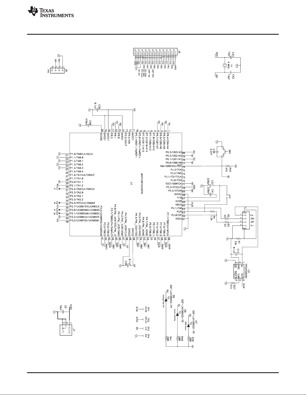
3.3 EV2400 Schematic
EV2400 Bill of Materials, Component Placement, Schematic
SLUU446A–June 2011– Revised September 2011 EV2400 EVM Interface Board
Submit Documentation Feedback
Figure 9. Schematic, Page 1
Copyright © 2011, Texas Instruments Incorporated
15
Page 16

+
+
EV2400 Bill of Materials, Component Placement, Schematic
www.ti.com
16
Figure 10. Schematic, Page 2
EV2400 EVM Interface Board SLUU446A–June 2011– Revised September 2011
Copyright © 2011, Texas Instruments Incorporated
Submit Documentation Feedback
Page 17

www.ti.com
EV2400 Bill of Materials, Component Placement, Schematic
Figure 11. Schematic, Page 3
SLUU446A–June 2011– Revised September 2011 EV2400 EVM Interface Board
Submit Documentation Feedback
Copyright © 2011, Texas Instruments Incorporated
17
Page 18

Evaluation Board/Kit Important Notice
Texas Instruments (TI) provides the enclosed product(s) under the following conditions:
The user assumes all responsibility and liability for proper and safe handling of the goods. Further, the user indemnifies TI from all
claims arising from the handling or use of the goods. Please read this user’s guide and, specifically, the EVM Warnings and
Restrictions notice below prior to handling the product. This notice contains important safety information about temperatures and
voltages. For additional information on TI’s environmental and/or safety programs, contact a TI field representative or visit
www.ti.com/esh.
No license is granted under any patent right or other intellectual property right of TI covering or relating to any machine, process, or
combination in which such TI products or services might be or are used. TI currently deals with a variety of customers for products,
and therefore our arrangement with the user is not exclusive. TI assumes no liability for applications assistance, customer product
design, software performance, or infringement of patents or services described herein.
Should this evaluation board/kit not meet the specifications indicated in the user’s guide, the board/kit may be returned within 30
days from the date of delivery for a full refund. THE FOREGOING LIMITED WARRANTY IS THE EXCLUSIVE WARRANTY MADE
BY SELLER TO BUYER AND IS IN LIEU OF ALL OTHER WARRANTIES, EXPRESSED, IMPLIED, OR STATUTORY,
INCLUDING ANY WARRANTY OF MERCHANTABILITY OR FITNESS FOR ANY PARTICULAR PURPOSE. EXCEPT TO THE
EXTENT OF THE INDEMNITY SET FORTH ABOVE, NEITHER PARTY SHALL BE LIABLE TO THE OTHER FOR ANY
INDIRECT, SPECIAL, INCIDENTAL, OR CONSEQUENTIAL DAMAGES.
Regulatory Information
This device complies with Part 15 of the FCC Rules. Operation is subject to the following two conditions: (1) This device may not
cause harmful interference, and (2) This device must accept any interference received, including interference that may cause an
undesired operation. Changes or modifications not expressly approved by the party responsible for compliance could void the
user’s authority to operate the equipment
This Class A digital apparatus complies with Canadian ICES-003. Changes or modifications not expressly approved by the party
responsible for compliance could void the user’s authority to operate the equipment. Cet appareil numérique de la classe A est
confor á la norme NMB-003 du Canada. Les changements ou les modifications pas expressément approuvés par la partie
responsable de la conformité ont pu vider l’user’; autorité de s pour actionner l’équipement.
EVM Warnings and Restrictions
It is important to operate this EVM within TI’s recommended specifications and environmental considerations per the user
guidelines. Failure to follow the guidelines may cause potential risk of personal injury, property damage, and/or unexpected
operation of the EVM. If there are any questions, please contact a TI field representative before connecting and/or enabling power
or other interface connections to the EVM.
During normal operation and within the EVM’s recommended ratings, some circuit components including but not limited to linear
regulators, switching transistors, pass transistors, current sense resistors, and heat sinks may have elevated case temperatures or
contain voltages exceeding safe touch levels. These types of devices, as applicable, can be identified using the EVM schematic in
this user's guide. When placing measurement probes near or on these devices during operation for evaluation purposes,
precautions should be taken against inadvertent contact with surfaces of elevated temperatures and/or voltages exceeding safe
touch levels.
As with all electronic evaluation tools, only qualified personnel knowledgeable in electronic measurement and diagnostics normally
found in development environments should use these EVMs.
Mailing Address: Texas Instruments, Post Office Box 655303, Dallas, Texas 75265
Copyright © 2011, Texas Instruments Incorporated
Page 19

www.ti.com
Revision History
Revision History
Changes from Original (June 2011) to A Revision ......................................................................................................... Page
• Deleted installer information ............................................................................................................ 3
NOTE: Page numbers for previous revisions may differ from page numbers in the current version.
SLUU446A–June 2011– Revised September 2011 Revision History
Submit Documentation Feedback
Copyright © 2011, Texas Instruments Incorporated
19
Page 20

IMPORTANT NOTICE
Texas Instruments Incorporated and its subsidiaries (TI) reserve the right to make corrections, modifications, enhancements, improvements,
and other changes to its products and services at any time and to discontinue any product or service without notice. Customers should
obtain the latest relevant information before placing orders and should verify that such information is current and complete. All products are
sold subject to TI’s terms and conditions of sale supplied at the time of order acknowledgment.
TI warrants performance of its hardware products to the specifications applicable at the time of sale in accordance with TI’s standard
warranty. Testing and other quality control techniques are used to the extent TI deems necessary to support this warranty. Except where
mandated by government requirements, testing of all parameters of each product is not necessarily performed.
TI assumes no liability for applications assistance or customer product design. Customers are responsible for their products and
applications using TI components. To minimize the risks associated with customer products and applications, customers should provide
adequate design and operating safeguards.
TI does not warrant or represent that any license, either express or implied, is granted under any TI patent right, copyright, mask work right,
or other TI intellectual property right relating to any combination, machine, or process in which TI products or services are used. Information
published by TI regarding third-party products or services does not constitute a license from TI to use such products or services or a
warranty or endorsement thereof. Use of such information may require a license from a third party under the patents or other intellectual
property of the third party, or a license from TI under the patents or other intellectual property of TI.
Reproduction of TI information in TI data books or data sheets is permissible only if reproduction is without alteration and is accompanied
by all associated warranties, conditions, limitations, and notices. Reproduction of this information with alteration is an unfair and deceptive
business practice. TI is not responsible or liable for such altered documentation. Information of third parties may be subject to additional
restrictions.
Resale of TI products or services with statements different from or beyond the parameters stated by TI for that product or service voids all
express and any implied warranties for the associated TI product or service and is an unfair and deceptive business practice. TI is not
responsible or liable for any such statements.
TI products are not authorized for use in safety-critical applications (such as life support) where a failure of the TI product would reasonably
be expected to cause severe personal injury or death, unless officers of the parties have executed an agreement specifically governing
such use. Buyers represent that they have all necessary expertise in the safety and regulatory ramifications of their applications, and
acknowledge and agree that they are solely responsible for all legal, regulatory and safety-related requirements concerning their products
and any use of TI products in such safety-critical applications, notwithstanding any applications-related information or support that may be
provided by TI. Further, Buyers must fully indemnify TI and its representatives against any damages arising out of the use of TI products in
such safety-critical applications.
TI products are neither designed nor intended for use in military/aerospace applications or environments unless the TI products are
specifically designated by TI as military-grade or "enhanced plastic." Only products designated by TI as military-grade meet military
specifications. Buyers acknowledge and agree that any such use of TI products which TI has not designated as military-grade is solely at
the Buyer's risk, and that they are solely responsible for compliance with all legal and regulatory requirements in connection with such use.
TI products are neither designed nor intended for use in automotive applications or environments unless the specific TI products are
designated by TI as compliant with ISO/TS 16949 requirements. Buyers acknowledge and agree that, if they use any non-designated
products in automotive applications, TI will not be responsible for any failure to meet such requirements.
Following are URLs where you can obtain information on other Texas Instruments products and application solutions:
Products Applications
Audio www.ti.com/audio Communications and Telecom www.ti.com/communications
Amplifiers amplifier.ti.com Computers and Peripherals www.ti.com/computers
Data Converters dataconverter.ti.com Consumer Electronics www.ti.com/consumer-apps
DLP® Products www.dlp.com Energy and Lighting www.ti.com/energy
DSP dsp.ti.com Industrial www.ti.com/industrial
Clocks and Timers www.ti.com/clocks Medical www.ti.com/medical
Interface interface.ti.com Security www.ti.com/security
Logic logic.ti.com Space, Avionics and Defense www.ti.com/space-avionics-defense
Power Mgmt power.ti.com Transportation and Automotive www.ti.com/automotive
Microcontrollers microcontroller.ti.com Video and Imaging www.ti.com/video
RFID www.ti-rfid.com
OMAP Mobile Processors www.ti.com/omap
Wireless Connctivity www.ti.com/wirelessconnectivity
TI E2E Community Home Page e2e.ti.com
Mailing Address: Texas Instruments, Post Office Box 655303, Dallas, Texas 75265
Copyright © 2011, Texas Instruments Incorporated
Page 21

Mouser Electronics
Authorized Distributor
Click to View Pricing, Inventory, Delivery & Lifecycle Information:
Texas Instruments:
EV2400
 Loading...