

Page 1
ISTEVO
I
F
E
GB
EVO
ACE500ET-ACE800E
MOTORIDUTTORI ELETTROMECCANICI PER CANCELLI SCORREVOLI
MANUALE ISTRUZIONI E CATALOGO RICAMBI
OPÉRATEURS ÉLECTROMÉCANIQUES POUR PORTAILS COULISSANTS
NOTICE D'INSTRUCTIONS ET CATALOGUE DES PIÈCES DE RECHANGE
MOTORREDUCTORES ELECTROMECÁNICOS PARA CANCELAS CORREDERAS
MANUAL DE INSTRUCCIONES Y CATÁLOGO DE PIEZAS DE REPUESTO
ELECTROMECHANICAL GEARMOTORS FOR SLIDING GATES
INSTRUCTIONS MANUAL AND SPARE PARTS CATALOGUE
V. 08-2009
D
NL
ELEKTROMECHANISCHE SCHIEBETORANTRIEBE
BEDIENUNGSANLEITUNG UND ERSATZTEILKATALOG
ELEKTROMECHANISCHE REDUCTIEMOTOREN VOOR SCHUIFPOORTEN
GEBRUIKERSHANDLEIDING EN ONDERDELENCATALOGUS
Telcoma srl - Via L. Manzoni, 11 - Z.I. Campidui - 31015 Conegliano - (TV) Italy
Tel. +39 0438-451099 - Fax +39 0438-451102 - Part. IVA 00809520265
http://www.telcoma.it E-mail: info@telcoma .it
Page 2
I F E
INFORMAZIONI GENERALI
I motoriduttori della serie EVO e ACE500ET ACE800E offrono un'ampia versatilità per
l'automazione di cancelli scorrevoli grazie alla
gamma di potenze, alle regolazioni di altezza e
profondità,aidispositividisicurezzainclusi.
Infatti, nei motori completi di centralina
elettronica, sono presenti dei sensori encoder
perlarilevazionedegliostacoli.
Per una sicura e corretta installazione vi
chiediamo, quindi, di leggere attentamente le
presenti istruzioni prestando particolare
attenzione al capitolo “AVVERTENZE
IMPORTANTI SULL'INSTALLAZIONE” e in
seguito di conservarle per una futura
consultazione.
INFORMATIONS GÉNÉRALES
Les opérateurs de la série EVO et
ACE800E
offrent une grande flexibilité pour
ACE500ET -
l'automatisation de portails coulissants grâce à
la gamme de puissances, aux réglages de
hauteur et profondeur, aux dispositifs de
sécuritéinclus.
En effet, les moteurs avec logique de
commande électronique sont équipés de
capteurs à encodeur pour la détection des
obstacles.
Pour une installationsûreetcorrecte,nousvous
prions donc de lire attentivement ces
instructionsen faisant particulièrement attention
au chapitre « RECOMMANDATIONS
IMPORTANTES POUR L'INSTALLATION » et
delesconserverpourtouteconsultationfuture.
INFORMACIONES GENERALES
Los motorreductores de la serie EVO y
ACE500ET - ACE800E
ofrecen una amplia
versatilidad para la automatización de
cancelas correderas gracias a la gama de
potencias, a las regulaciones de altura y
profundidad y a los dispositivos de seguridad
incluidos.
En efecto, en los motores equipados con
central electrónica, se encuentran presentes
sensores codificadores para la detección de
losobstáculos.
Para llevar a cabo una instalación segura y
correcta le rogamos, por lo tanto, que lea
atentamente las presentes instrucciones
prestando una atención particular al capítulo
“ADVERTENCIAS IMPORTANTES SOBRE
LA INSTALACIÓN” y que las conserve para
unaconsultafutura.
DATI TECNICI
Tensione di alimentazione
Alimentazione motore
Peso max cancello
Forza di spinta
Corrente max assorbita
Potenza max assorbita
Condensatore
Coppia nominale
Velocità cancello
Temp. di funzionamento
Intervento termoprotezione
Grado di protezione
Encoder
Intermittenza lavoro
Peso
Finecorsa elettronico
Finecorsa meccanico
Centrale elettronica incorporata
Classe di isolamento
Lubrificante grasso
Lubrificante olio
DONNÉES TECHNIQUES
Tension d'alimentation
Alimentation moteur
Poids max. portail
Force de poussée
Courant max. absorbé
Puissance max. absorbée
Condensateur
Couple nominal
Vitesse portail
Température de fonctionnement
Intervention protection thermique
Indice de protection
Encodeur
Intermittence travail
Poids
Fin de course électronique
Fin de course mécanique
Logique électronique incorporée
Classe d'isolement
Lubrifiant graisse
Lubrifiant huile
DATOS TÉCNICOS
Tensión de alimentación
Alimentación motor
Peso máx cancela
Fuerza de empuje
Corriente máx absorbida
Potencia máx absorbida
Condensator
Par nominal
Velocidad cancela
Temp. de funcionamiento
Intervención termoprotección
Grado de protección
Encoder
Intermitencia trabajo
Peso
Fin de carrera electrónico
Fin de carrera mecánico
Central electrónica incorporada
Clase de aislamiento
Lubrificante grasa
Lubrificante aceite
Um EVO600 EVO600SC EVO800 EVO1200 ACE800E
Vac 230 230 230 230
V 230Vac 230Vac 230Vac 230Vac
Kg 600 600 800 1200
N 540 540 640 1200
A 3,4 3,4 3,4 5,2
VA 800 800 800 1100
μF 16 16 20 20
Nm 21 21 24 45
m/min 10 10 10 10
°C -20+70 -20+70 -20+70 -20+70 -20+70
°C 150 150 150 150
IP
54 54 54 54 54
SI/YES SI/YES SI/YES SI/YES
SI/YES
%40
Kg 13 13 15 17
40 60 60
SI/YES - SI/YES SI/YES
- SI/YES - -
SI/YES - SI/YES SI/YES SI/YES
FF
TS 10 TS 10 - - TS10
- - TS 20 TS 40
F
FF
230
24Vdc
800
640
2,2
300
-
24
11
-
60
13
SI/YES
-
-
ACE500ET
230
24Vdc
500
500
1,5
200
-
18
11
-20+70
-
54
SI/YES
60
12
SI/YES
-
SI/YES
-
TS10
-
2
Page 3
GB D NL
GENERAL INFORMATION
The EVO and series
ACE500ET - ACE800E
gearmotors offer ample flexibility for the
automation of sliding gates thanks to the range
of powers, height and depth adjustment and
includedsafetydevices.
In fact, the motor with electronic control unit
includes encoder sensors for obstacle
detection.
Therefore, in order that the installation is
performed in a safe and correct manner, we
kindly ask you to carefully read the present
instructions giving particularattentionto chapter
“IMPORTANT INSTALLATION WARNINGS"
and tokeepthese instructions inasafe place for
futurereference.
ALLGEMEINE AUSKÜNFTE
Die Antriebe der Serien EVO und
ACE800E
bieten dank den verschiedenen
ACE500ET -
Leistungen, denHöhen- undTiefenverstellungen
und den eingeschlossenen
Sicherheitsvorrichtungen eine große
Vielseitigkeit bei der Automatisierung von
Schiebetoren.
Die mit elektronischer Steuerung ausgestatteten
Antriebe verfügen über Encodersensoren zur
WahrnehmungderHindernisse.
Für eine sichere und korrekte Installation bitten
wir Sie daher, die vorliegenden Anweisungen
und insbesondere das Kapitel „WICHTIGE
HINWEISE ZUR INSTALLATION „aufmerksam
zu lesen und sie dann für ein zukünftiges
Nachschlagenaufzubewahren.
ALGEMENE INFORMATIE
De reductiemotoren uit de serie EVO en
ACE500ET-ACE800E
zijnuitermateveelzijdig
voor het automatiseren van schuifpoorten
dankzij eenheelscala aan vermogen,afstelling
in hoogte en diepte, veiligheidsinrichtingen
inbegrepen.
In de motoren voorzien van een elektronische
besturingseenheid, bevinden zich
encodersensorenvoorobstakeldetectie.
Voor een veilige en correcte installatie
verzoeken wij u daarom deze aanwijzingen
aandachtig doorte lezenen in hetbijzonder het
hoofdstuk “BELANGRIJKE AANWIJZINGEN
VOOR HET INSTALLEREN” en ze daarna te
bewaren om ze in de toekomst te kunnen
raadplegen.
TECHNICAL SPECIFICATIONS
Power Supply voltage
Motor power supply
Max. gate weight
Thrust force
Max. absorbed current
Max absorbed power
Capacitor
Nominal torque
Gate speed
Operating time
Thermal cut-out
Protection class
Encoder
Operating intervals
Weight
Electronic limit switch
Mechanical stop
Incorporated electronic control unit
Insulation class
Grease lubricant
Oil lubricant
TECHNISCHE DATEN
Spannungsversorgung
Motorversorgung
Höchstgewicht des Tors
Schubkraft
Max. Stromaufnahme
Max. Leistungsaufnahme
Kondensator
Nenndrehmoment
Torgeschwindigkeit
Betriebstemp.
Auslösung des Wärmeschutzes
Schutzart
Encoder
Betriebsintermittenz
Gewicht
Elektronischer Endschalter
Mechanischer Endschalter
Eingebaute elektronische Steuerung
Isolationsklasse
Fettschmierung
Ölschmierung
TECHNISCHE GEGEVENS
Spanning stroomvoorziening
Stroomvoorziening motor
Max gewicht poort
Duwkracht
Mas opgenomen stroom
Max opgenomen vermogen
Condensator
Nominale koppel
Snelheid poort
Bedrijfstemp
Inwerkingtreding oververhittingsbeveiliging
Beschermingsklasse
Encoder
Onderbreking bedrijf
Gewicht
Elektronische eindschakelaar
Mechanische eindaanslag
Ingebouwde besturingseenheid
Isoleringsklasse
Smeermiddel vet
Smeermiddel olie
Um EVO600 EVO600SC EVO800 EVO1200
Vac 230 230 230 230
V 230Vac 230Vac 230Vac 230Vac
Kg 600 600 800 1200
N 540 540 640 1200 640
A 3,4 3,4 3,4 5,2
VA 800 800 800 1100
μF 16 16 20 20
Nm 21 21 24 45
m/min 10 10 10 10 11
°C -20+70 -20+70 -20+70 -20+70
°C 150 150 150 150
54 54 54 54 54
IP
SI/YES
SI/YES SI/YES SI/YES SI/YES
%40 40 60 60
Kg 13 13 15 17
SI/YES - SI/YES SI/YES
- SI/YES - -
SI/YES - SI/YES SI/YES
FF
TS 10 TS 10 - - TS10
- - TS 20 TS 40 -
F
FF
ACE800E
230
24Vdc
800
2,2
300
-
24
-20+70
-
60
13
SI/YES
-
SI/YES
ACE500ET
230
24Vdc
500
500
1,5
200
-
18
11
-20+70
-
54
SI/YES
60
12
SI/YES
-
SI/YES
-
TS10
-
3
Page 4
I
F
E
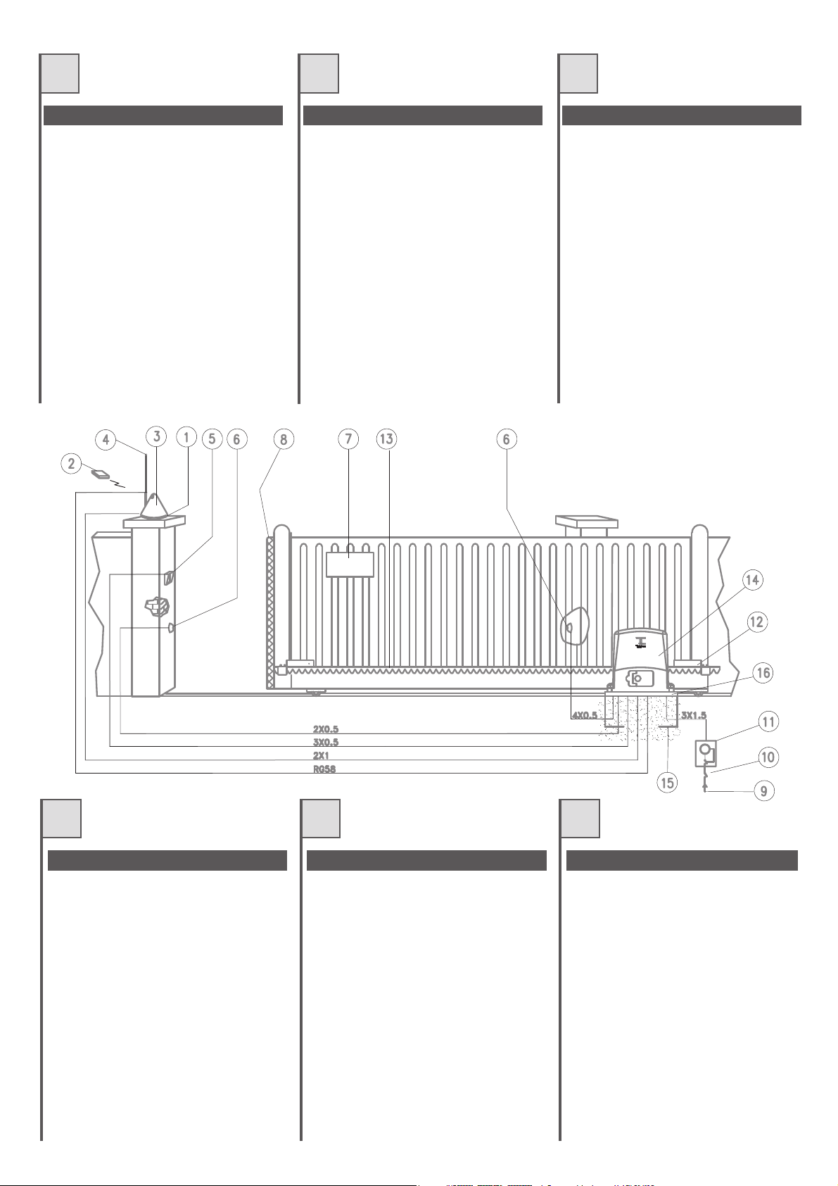
QUADRO D'INSIEME
1.Supportoperlampeggiatore+antenna
2.Radiocomando
3.Lampeggiatore
4.Antenna
5.Selettore
6.Fotocellula
7.Cartellodiavvertenza
8.Bordoingomma
9.Lineadialimentazione
10.Interruttoregenerale
11.Interruttoredifferenziale
12.Magnetedifinecorsa
13.Cremagliera
14.Motoriduttore
15.Contropiastradifondazione(optional)
16.Piastradifissaggio
VUE D'ENSEMBLE
1.Supportpourclignotant+antenne
2.Radiocommande
3.Clignotant
4.Antenne
5.Sélecteur
6.Photocellule
7.Panneaudesignalisation
8.Bordencaoutchouc
9.Ligned'alimentation
10.Interrupteurgénéral
11.Interrupteurdifférentiel
12.Aimantdefindecourse
13.Crémaillère
14.Opérateur
15.Contre-plaquedefondation(option)
16.Plaquedefixation
VISIÓN DE CONJUNTO
1.Soporteparaluzintermitente+antena
2.Radiocontrol
3.Luzintermitente
4.Antena
5.Selector
6.Fotocélula
7.Carteldeadvertencia
8.Bordedegoma
9.Líneadealimentación
10.Interruptorgeneral
11.Interruptordiferencial
12.Magnetodefindecarrera
13.Cremallera
14.Motorreductor
15.Contraplacadecimentación(facultativo)
16.Placadefijación
GB
GENERAL LAYOUT
1.Aerial+flashinglightsupport
2.Remotecontrol
3.Flashinglight
4.Aerial
5.Selectorswitch
6.Photocell
7.Warningsign
8.Rubberedge
9.Powerline
10.Mainswitch
11.Differential switch
12.Limitswitchmagnet
13.Rack
14.Gearmotor
15.Foundationbaseplate(optional)
16.Fixingplate
4
D NL
GESAMTANSICHT
1.HalterungfürBlinkleuchte+Antenne
2.Funksteuerung
3.Blinkleuchte
4.Antenne
5.Schlüsseltaster
6.Fotozelle
7.Warnschild
8.Gummileiste
9.Versorgungslinie
10.Hauptschalter
11.Differentialschalter
12.Endschaltermagnet
13.Zahnstange
14.Getriebemotor
15.Fundamentgegenplatte(Optional)
16.Ankerplatte
OVERZICHTSTEKENING
1.Steunvoorknipperlicht+antenne
2.Afstandsbediening
3.Knipperlicht
4.Antenne
5.Keuzeschakelaar
6.Fotocel
7.Waarschuwingsbord
8.Rubberrand
9.Leidingstroomvoorziening
10.Hoofdschakelaar
11.Differentiaalschakelaar
12.Magneeteindschakelaar
13.Tandheugel
14.Reductiemotor
15.Contrafunderingsplaat(apartleverbaar)
16.Bevestigingsplaat
Page 5
I
VERIFICHE PRELIMINARI CONTRÔLES PRÉLIMINAIRES VERIFICACIONES PRELIMINARES
F
E
Prima di passare all' installazione si consiglia di
effettuareleseguentiverificheeoperazioni.
1. Lastruttura delcancello deve essere solida e
appropriata.
2. Durante la sua corsa, il cancello non deve
presentaresbandamentilaterali.
3. Il sistema ruote/rotaia inferiore e rulli/guida
superiore deve scorrere regolarmente senza
attriti.
4. Devono essere installate delle battute di
arresto meccanico delcancelloscorrevolesia
inaperturacheinchiusura.
5. Nei cancelli preesistenti eliminarel'eventuale
serraturamanuale.
6. Portare alla base del cancello le canaline,
aventi un diametro, 25÷50 mm, necessarie
per il passaggio dei vari cavi elettrici quali
alimentazione di rete, fotocellula,
lampeggiatore,selettoreachiave,etc.
Avant de passer à l'installation, nous
conseillons d'effectuer les vérifications et
opérationsquisuivent.
1. La structure du portail doit être solide et
appropriée.
2. Durant sa course, le portail ne doit pas
présenterd'inclinaisonslatérales.
3.Le système roues/rail inférieur et
galets/glissière supérieure doit coulisser
régulièrementsansfrottements.
4. Des butées d'arrêt mécanique du portail
coulissant doivent être installées aussi bien
enouverturequ'enfermeture.
5. Dans les portails préexistants, éliminer
l'éventuelleserruremanuelle.
6.Amenerjusqu'àla base du portaillesgaines,
d'un diamètre de 25÷50 mm, nécessaires
pour le passage des différents câbles
électriques comme l'alimentation de
secteur, les photocellules, le clignotant, le
sélecteur a clé, etc.
Antes de pasar a la instalaciónleaconsejamos
que efectúe las siguientes verificaciones y
operaciones.
1. La estructura de la cancela tiene que ser
sólidayapropiada.
2. Durante su recorrido, la cancela no tiene
quepresentarinclinacioneslaterales.
3.El sistema ruedas/carril inferior y
rodillos/guía superiortiene que desplazarse
regularmentesinroces.
4. Tienen que instalarse topes de parada
mecánicos de la cancela corredera tanto en
laaperturacomoenelcierre.
5. En las cancelas preexistentes elimine la
eventualcerraduramanual.
6. Coloque en la base de la cancela los
canales, con un diámetro de 25÷50 mm,
que son necesarios para hacer pasar los
diversos cables eléctricos como el de
alimentación de red, el de la fotocélula, el
de la luz intermitente, el del selector con
llave, etc.
GB D NL
PRELIMINARY CONTROLS
The following controls and operations should
ideally be performedbeforecommencingwith
installation.
1. The gate structure must be solid and
appropriate.
2. The gate should have no lateral deviation
duringitsmovement.
3. The lowertrack/wheeland upper guide/wheel
systemmustslideevenlywithoutfriction.
4. The sliding gate mechanical stops must be
installedbothinopeningaswellasinclosing.
5. Remove the manual lock of already existing
gates.
6. A channel with a diameter of25÷50 mm must
be taken to the base of the gate in order to
pass the cables for the mains power supply,
photocell, flashing light, key operated selector
switch,etc.
ÜBERPRÜFUNGEN UND VORBEREITUNGEN
Bevor man auf die Installation übergeht, sollten
folgende Überprüfungen und Vorgänge
ausgeführtwerden:
1. Die Torstruktur muss solide und geeignet
sein.
2. Das Tor darf während seines Laufs seitlich
nichtentgleisen.
3. Die Räder auf der unteren Schiene und die
Rollen in der oberen Führung müssen
regelmäßigundohneReibungengleiten.
4. Das Schiebetor muss über mechanische
AnschlägesowohlinderÖffnung
alsauchinder Schließung verfügen.
5. An bereits vorhandenen Toren muss das
eventuelle manuelle Schloss entfernt
werden.
6. Die Kanäle mit einem Durchmesser von
25÷50 mm zum Durchführen der
verschiedenen elektrischen Kabel
(Netzstromversorgung, Fotozelle,
Blinkleuchte, Schlüsseltaster, usw.) bis zur
BasisdesTorsführen.
CONTROLES VOORAF
Voordat u tot installatie over gaat is het
raadzaam onderstaande controles en
handelingenuittevoeren.
1. De poort moet een stevige en adequate
structuurhebben.
2. Tijdens zijnloop mag depoort niet zijdelings
uithetgeleidingssysteemkomen.
3. Het systeem wielen/rails aan de onderzijde
en rollen/geleiding aan de bovenzijde moet
regelmatigverschuivenzonderwrijvingen.
4. Er dienen mechanische stops bij de
schuifpoort zowel aan de openings- als
sluitzijdeaangebrachtteworden.
5. Bij reeds bestaande poorten dient u een
eventueel slot met handbediening weg te
halen.
6. Breng aan de onderzijde van de poort de
kabelgootjes met een doorsnede van,
25÷50 mm, waardoor de verschillende
elektriciteitskabels zoalsstroomtoevoer van
het net, fotocel, knipperlicht,
sleutelschakelaar,etc.moetenlopen.
5
Page 6

I
F
E
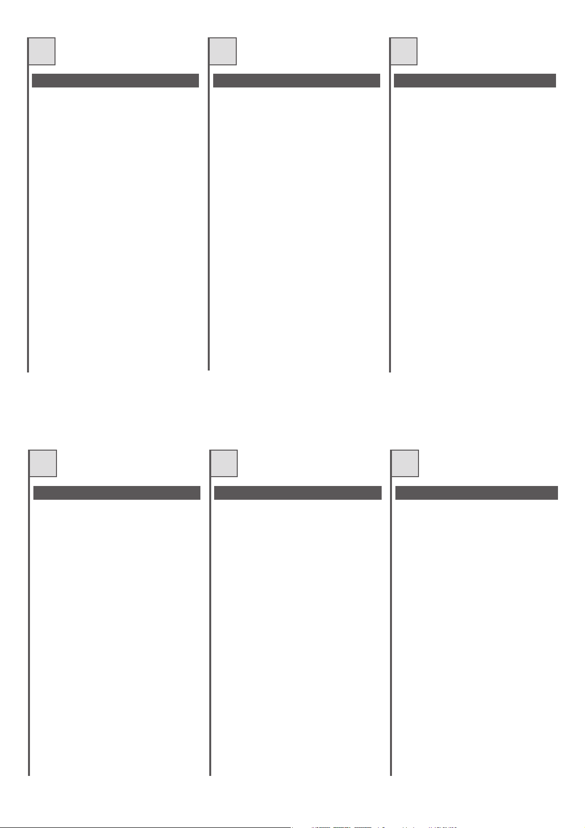
INSTALLAZIONE SU PIASTRADI
FONDAZIONE (OPZIONALE)
E79G;D7 G@A E53HA 6; 8A@63L;A@7 F7@7@6A
5A@FA 67>>7 ?;EGD7 67>>3 B;3EFD3 6; 8A@63L;A@7
;9
Prestare molta attenzione al verso di
montaggio. I fori per il passaggio delle
canalinedevonotrovarsiasinistra(fig.2).
>>A99;3D7 @7>>A E53HA >7 53@3>;@7 6;3? ??
j B7D ;> B3EE399;A 67; 53H; 6;
3>;?7@F3L;A@7 7 6; 5A>>793?7@FA 7EF7D@A
@@793D7 @7> 53>57EFDGLLA >7 53@3>;@7 7 >3
B;3EFD3 6; 8A@63L;A@7 6ABA 3H7D@7 5A@FDA>>3FA
5A@ >3GE;>;A 6; G@3 >;H7>>3 >7 CGAF7 7
>AD;LLA@F3>;FZ +;EB7FF3D7 ?;EGD7 7 3@9A>;
;@6;53F; ;@ ;9 3 ;@EF3>>3L;A@7 67EFD3 7 ;@
;9 4 ;@EF3>>3L;A@7 E;@;EFD3 D3BBD7E7@F3@A
;> ?;@;?A ;@6;EB7@E34;>7 B7D G@ B7D87FFA
355ABB;3?7@FA FD3 B;9@A@7 7 5D7?39>;7D3
Prestare molta attenzioneallequote indicate
nellafigura4.
H7@FG3>; B;55A>7 ;?BD75;E;A@; 6;
BAE;L;A@3?7@FA ;@ 3>F7LL3 7 BDA8A@6;FZ 67>>3
B;3EFD3 6; 8A@63L;A@7 BAEEA@A 5A?G@CG7
7EE7D7 5ADD7FF7 397@6A EG557EE;H3?7@F7 EG>
E;EF7?3 6; D79A>3L;A@7 67> ?AFAD;6GFFAD7
;EE3D7 ;> ?AFAD7 EG>>3 B;3EFD3 EA>A CG3@6A ;>
53>57EFDGLLA E3DZ B7D87FF3?7@F7 EA>;6;8;53FA 7
3E5;G93FA
INSTALLATION SUR PLAQUE DE
FONDATION (OPTION)
D7GE7D G@ FDAG 7@ F7@3@F 5A?BF7 67E
6;?7@E;A@E 67 >3 B>3CG7 67 8A@63F;A@ ;9
Faire trèsattention ausens de montage. Les
trous pour le passage desgaines doivent se
trouveràgauche(fig.2).
%A97D 63@E >7 FDAG >7E 93;@7E 6;3? ??
j BAGD >7 B3EE397 67E 5\4>7E
63>;?7@F3F;A@ 7F 67 5A@@7J;A@ 7JF`D;7GD7
'AK7D 63@E >7 4`FA@ >7E 93;@7E 7F >3 B>3CG7 67
8A@63F;A@ 3BD_E 7@ 3HA;D 5A@FDh>` 3H75 G@
@;H73G >7E 6;EF3@57E 7F >:AD;LA@F3>;F`
+7EB75F7D >7E ?7EGD7E 7F >7E 3@9>7E ;@6;CG`E
63@E >3 ;9 3 ;@EF3>>3F;A@ 6DA;F7 7F 63@E >3
;9 4 ;@EF3>>3F;A@ 93G5:7
>>7E D7BD`E7@F7@F >7 ?;@;?G? ;@6;EB7@E34>7
BAGD G@ 355AGB>7?7@F B3D83;F 7@FD7 B;9@A@ 7F
5D`?3;>>_D7
Faire très attention aux mesures indiquées
danslafigure4.
%7E `H7@FG7>>7E B7F;F7E ;?BD`5;E;A@E 67
BAE;F;A@@7?7@F 7@ :3GF7GD 7F BDA8A@67GD 67 >3
B>3CG7 67 8A@63F;A@ B7GH7@F aFD7 5ADD;9`7E
63@E FAGE >7E 53E 7@ 39;EE3@F EG557EE;H7?7@F
EGD >7 EKEF_?7 67 D`9>397 67 >AB`D3F7GD
;J7D >7 ?AF7GD EGD >3 B>3CG7 G@;CG7?7@F CG3@6
>7 4`FA@ E7D3 5A?B>_F7?7@F EA>;6;8;` 7F E75
INSTALACIÓN SOBRE PLACADE
CIMENTACIÓN (OPCIONAL)
875Fl7 G@3 7J53H35;g@ 67 5;?7@F35;g@
F7@;7@6A 7@ 5G7@F3 >3E ?76;63E 67 >3 B>353
67 5;?7@F35;g@ ;9
Preste mucha atención al sentido del
montaje. Losorificiospara el pasode los
canales tienen que encontrarse a la
izquierda(fig.2).
A>ACG7 >AE 53@3>7E 7@ >3 7J53H35;g@
6;[? ?? j B3D3 :357D B3E3D >AE
534>7E 67 3>;?7@F35;g@ K 67 5A@7J;g@
7JF7D@3
G4D3 5A@ :AD?;9g@ >AE 53@3>7E K >3 B>353
67 5;?7@F35;g@ 67EBG`E 67 :347D
5A@FDA>36A 5A@ >3 3KG63 67 G@ @;H7> >3E
5AF3E K >3 :AD;LA@F3>;636 +7EB7F7 >3E
?76;63E K >AE [@9G>AE CG7 E7 ;@6;53@ 7@ >3
;9 3 ;@EF3>35;g@ 67D75:3 K 7@ >3 ;9 4
;@EF3>35;g@ ;LCG;7D63
+7BD7E7@F3@ 7> ?c@;?A ;@6;EB7@E34>7 B3D3
A4F7@7D G@ 35AB>3?;7@FA B7D875FA 7@FD7
B;eg@ K 5D7?3>>7D3
Preste mucha atención a las cotas
indicadasenlafigura4.
H7@FG3>7E B7CG7e3E ;?BD75;E;A@7E 67
7?B>3L3?;7@FA 7@ 3>FGD3 K BDA8G@6;636 67 >3
B>353 67 5;?7@F35;g@ E7 BG767@ 5ADD79;D 67
FA63E 8AD?3E 355;A@3@6A EG57E;H3?7@F7 7>
E;EF7?3 67 D79G>35;g@ 67> ?AFADD76G5FAD
;<7 7> ?AFAD EA4D7 >3 B>353 Eg>A 5G3@6A 7>
:AD?;9g@ E7 :3K3 EA>;6;8;536A K E7536A
B7D875F3?7@F7
;9 44
;9 44
;9 44
45
45
;93 443 ;94 444
6
Page 7
GB D NL
INSTALLATION ON THE FOUNDATION
PLATE (OPTIONAL)
;9 3 8AG@63F;A@ :A>7 F3=;@9 ;@FA
5A@E;67D3F;A@ F:7 6;?7@E;A@E A8 F:7
8AG@63F;A@ B>3F7 ;9
Take particular care of the assembly
direction. The holes for the passage of the
channelmustbeontheleft(fig.2).
)>357 F:7 5:3@@7> 6;3 j ?? 8AD F:7
BAI7D EGBB>K 534>7 3@6 7JF7D@3> 5A@@75F;A@E
;@ F:7 :A>7
,G4?7D97 F:7 5:3@@7>E 3@6 8AG@63F;A@ B>3F7
;@FA F:7 5A@5D7F7 BD7H;AGE>K :3H;@9 5:75=76
F:7 :7;9:FE 3@6 >7H7> I;F: 3 EB;D;F >7H7>
A?B>K I;F: F:7 ?73EGD7?7@FE 3@6 3@9>7E
;@6;53F76 ;@ ;9 3 D;9:F:3@6 ;@EF3>>3F;A@
3@6 ;@ ;9 4 >78F:3@6 ;@EF3>>3F;A@ F:3F
D7BD7E7@F F:7 ?;@;?G? @757EE3DK 8AD 3
B7D875F 5AGB>;@9 47FI77@ F:7 D35= 3@6 F:7
B;@;A@
Pay particular attention to the heights
indicatedinFig4.
)AEE;4>7 BAE;F;A@;@9 ;?B7D875F;A@E ;@ F:7 :7;9:F
3@6 67BF: A8 F:7 8AG@63F;A@ B>3F7 53@ 47
EG4E7CG7@F>K 5ADD75F76 F:DAG9: F:7 36<GEF?7@F
EKEF7? A8 F:7 973D?AFAD
;J F:7 973D?AFAD A@ F:7 B>3F7 A@>K I:7@ F:7
5A@5D7F7 :3E B7D875F>K :3D67@76 3@6 ;E
5A?B>7F7>K 6DK
NSTALLATION AUF FUNDAMENTPLATTE
(OPTIONAL)
.@F7D 7Dn5=E;5:F;9G@9 67D 4?7EEG@97@
67D G@63?7@FB>3FF7 44 7;@ G@63?7@F
3GE9D347@
Den Montagesinn genau beachten. Die
Löcher zum Durchführen der Kanäle
müssensichlinksbefinden(Abb.2).
"@ 67D GE9D34G@9 6;7 $3@]>7 GD5:? ??
j LG? GD5:8n:D7@ 67D /7DEAD9G@9E=347>
G@6 67D 7JF7D@7@ /7D4;@6G@9E=347>
G@F7D4D;@97@
;7 &3Y7 G@6 6;7 03397D75:F7 67D $3@]>7
G@6 67D G@63?7@FB>3FF7 ?;F 7;@7D
03EE7DI3397 =A@FDA>>;7D7@ 63@@ 6;7E7 ;?
7FA@ H7DE7@=7@ ;7 ;@8 67@ 44 3
"@EF3>>3F;A@ D75:FE G@6 4 "@EF3>>3F;A@ >;@=E
3@979747@7@ &3Y7 4735:F7@ M
,;7 E;@6 6;7 8nD 7;@7 7;@I3@68D7;7 $ABB>G@9
LI;E5:7@ +;FL7> G@6 23:@EF3@97 G@476;@9F
@AFI7@6;97@ &;@67EF?3Y7
Die in Abbildung 4 angegebenen Maße
genauestenseinhalten.
$>7;@7 .@97@3G;9=7;F7@ 47;? )AE;F;A@;7D7@ 67D
G@63?7@FB>3FF7 ;@ !i:7 G@6 -;787 =i@@7@
3G5: EB]F7D ?;F 67? ;@EF7>>EKEF7? 67E
@FD;74E 47D;5:F;9F I7D67@
7@ @FD;74 7DEF 3G8 67D )>3FF7 4787EF;97@ I7@@
67D 7FA@ 93@L 87EF G@6 FDA5=7@ ;EF
INSTALLATIE OP FUNDERINGSPLAAT
(APART LEVERBAAR)
&33= 77@ 8G@67D;@9EBG@F 7@ :AG6 633D4;<
D7=7@;@9 ?7F 67 38?7F;@97@ H3@ 67
8G@67D;@9EB>33F 384
Let heel goed op de richting van montage.
De boringen waar de kabelgootjes
doorheen moeten lopen, moeten zich links
bevinden(afb.2).
D7@9 67 =347>9AAF<7E 6;3? ?? j
HAAD 67 =347>E HAAD EFDAA?HAADL;7@;@9 7@
7JF7D@7 33@E>G;F;@9 ;@ 67 8G@67D;@9EBGF 33@
%79 67 =347>9AAF<7E 7@ 67 8G@67D;@9EB>33F
;@ :7F 47FA@ @363F G ?7F 47:G>B H3@ 77@
I3F7DB3E 67 I33D67@ 7@ :7F 87;F A8 3>>7E
:AD;LA@F33> ;E 975A@FDA>77D6 :74F '77? 67
38?7F;@97@ 7@ :A7=7@ ;@ 35:F LA3>E 6;7 AB
384 3 ;@EF3>>3F;7 D75:FE 7@ AB 384 4
;@EF3>>3F;7 >;@=E 33@9797H7@ L;<@ L;< L;<@ :7F
34EA>GF7 ?;@;?G? 63F @AA6L3=7>;<= ;E HAAD
77@ B7D875F7 =ABB7>;@9 FGEE7@ DA@6E7> 7@
F3@6:7G97>
Let goed opdeopafbeelding4 aangegeven
waarden.
H7@FG7>7 =>7;@7 A@@3GI=7GD;9:767@ ;@
:AA9F7 7@ 6;7BF7 4;< :7F B>33FE7@ H3@ 67
8G@67D;@9EB>33F =G@@7@ 75:F7D H7D:A>B7@
IAD67@ 6AAD >3F7D :7F 38EF7>EKEF77? H3@ 67
D76G5F;7?AFAD F7 974DG;=7@
7H7EF;9 67 ?AFAD B3E AB 67 B>33F I3@@77D :7F
47FA@ HA>=A?7@ 6DAA9 7@ :3D6 ;E
;9 44
;9 44
;9 44
45
45
;93 443 ;94 444
7
Page 8
$
!
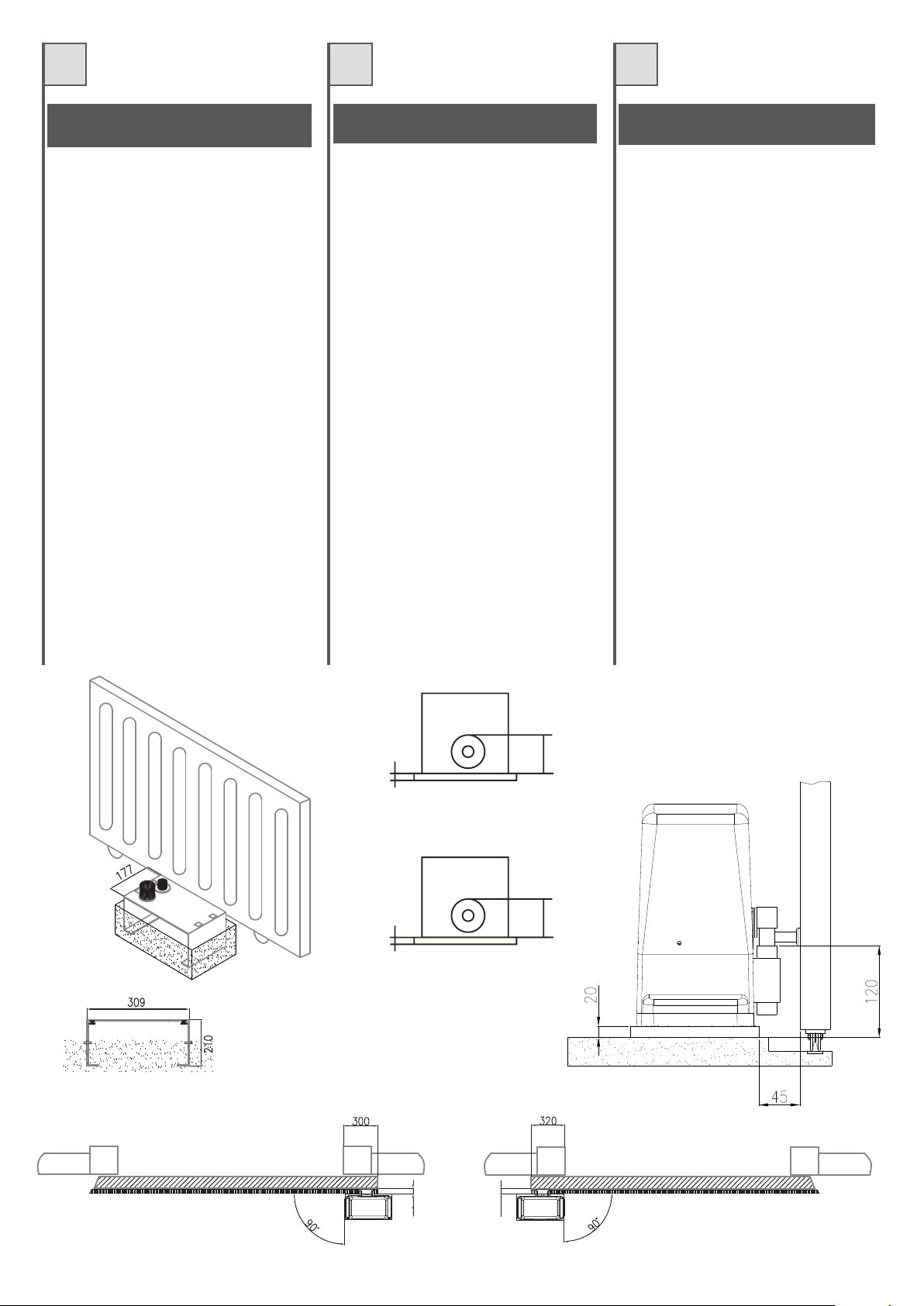
$)./''5$*) .0 +$./- $)
*/5$*)
,7 ;> 53@57>>A _ BDAHH;EFA 6; EA>;6A 43E3?7@FA ;@
57?7@FA ;> ?AFAD;6GFFAD7 BGf 7EE7D7 3@5AD3FA
6;D7FF3?7@F7 3> EGA>A GE3@6A >3 B;3EFD3 6;
8;EE399;A 8AD@;F3 3EE;7?7 3> ?AFAD;6GFFAD7 5A@
CG3FFDA DA4GEF; F3EE7>>; 36 7EB3@E;A@7 8;9
+E:FG6E: @B?G6 6GG:AM>BA: 6??: DHBG: >A9>86G:
A:??6;><HE6
H7@FG3>; B;55A>7 ;?BD75;E;A@; 6;
BAE;L;A@3?7@FA ;@ 3>F7LL3 7 BDA8A@6;FZ 67>>3
B;3EFD3 6; 8;EE399;A BAEEA@A 5A?G@CG7 7EE7D7
5ADD7FF7 397@6A EG557EE;H3?7@F7 EG> E;EF7?3 6;
D79A>3L;A@7 67> ?AFAD;6GFFAD7
$)./''/$*) .0- +',0 !*0-)$
,; >7 BADF3;> 7EF ?G@; 6G@7 EA>;67 43E7 7@
5;?7@F >AB`D3F7GD B7GF aFD7 8;J` 6;D75F7?7@F
EGD >7 EA> 7@ GF;>;E3@F >3 B>3CG7 67 8;J3F;A@
8AGD@;7 3H75 >AB`D3F7GD 3H75 CG3FD7 9DAEE7E
5:7H;>>7E Z 7JB3@E;A@ 8;9
!6>E: GEYF 6GG:AG>BA 6HK @:FHE:F >A9>DH:F
96AF?6;><HE:
%7E `H7@FG7>>7E B7F;F7E ;?BD`5;E;A@E 67
BAE;F;A@@7?7@F 7@ :3GF7GD 7F BDA8A@67GD 67 >3
B>3CG7 67 8;J3F;A@ B7GH7@F aFD7 5ADD;9`7E 63@E
FAGE >7E 53E 7@ 39;EE3@F EG557EE;H7?7@F EGD >7
EKEF_?7 67 D`9>397 67 >AB`D3F7GD
$)./'$) .*- +'
.*($)$./-
,; >3 53@57>3 6;EBA@7 67 G@3 43@5363 67
57?7@FA Eg>;63 7> ?AFADD76G5FAD E7 BG767 8;<3D
6;D75F3?7@F7 7@ 7> EG7>A GF;>;L3@6A >3 B>353 67
8;<35;g@ CG7 E7 EG?;@;EFD3 <G@FA 5A@ 7>
?AFADD76G5FAD 5A@ 5G3FDA F35AE 67 7JB3@E;g@
DA4GEFAE 8;9
+E:FG: @H8=6 6G:A8>A 6 ?6F 8BG6F >A9>8696F
:A?6;><HE6
H7@FG3>7E B7CG7e3E ;?BD75;E;A@7E 67
7?B>3L3?;7@FA 7@ 3>FGD3 K BDA8G@6;636 67 >3
B>353 67 8;<35;g@ E7 BG767@ 5ADD79;D 67 FA63E
8AD?3E 355;A@3@6A EG57E;H3?7@F7 7> E;EF7?3
67 D79G>35;g@ 67> ?AFADD76G5FAD
;9 44
;9 44
"
$)./''/$*) *) /# .0++'$
+'/
"8 F:7 93F7 3>D736K :3E 3 EA>;6 5A@5D7F7 43E7
F:7@ F:7 973D?AFAD 53@ 47 8;J76 6;D75F>K FA F:7
9DAG@6 GE;@9 F:7 8;J;@9 B>3F7 EGBB>;76 3>A@9
I;F: F:7 973D?AFAD I;F: 8AGD EFGD6K 7JB3@E;A@
4A>FE 8;9
+6L C6EG>8H?6E 6GG:AG>BA GB G=: =:><=GF
>A9>86G:9>A!><
)AEE;4>7 BAE;F;A@;@9 ;?B7D875F;A@E ;@ F:7
:7;9:F 3@6 67BF: A8 F:7 8AG@63F;A@ B>3F7 53@ 47
EG4E7CG7@F>K 5ADD75F76 F:DAG9: F:7
36<GEF?7@F EKEF7? A8 F:7 973D?AFAD
)'
$)./''/$*) 0! ($/" '$ ! -/ +'//
3>>E 63E -AD ?;F 7;@7? EA>;67@
27?7@F8G@63?7@F H7DE7:7@ ;EF =3@@ 67D
@FD;74 ?;F !;>87 67D @=7DB>3FF7 ?;F97>;787DF
G@6 H;7D DA4GEF7@ ,BD7;L6n47>@ 44 6;D7=F
?;F 67? A67@ H7D3@=7DF I7D67@
>: >A 77>?9HA< 6A<:<:7:A:A (6O:
<:A6H:FG:AF:>A=6?G:A
$>7;@7 .@97@3G;9=7;F7@ 47;? )AE;F;A@;7D7@ 67D
@=7DB>3FF7 ;@ !i:7 G@6 -;787 =i@@7@ 3G5:
EB]F7D ?;F 67? ;@EF7>>EKEF7? 67E @FD;74E
47D;5:F;9F I7D67@
$)./''/$ *+ ( " ' 1 -
+'/
>E 67 BAADF HAADL;7@ ;E H3@ 77@ EF7H;97
9DA@6B>33F H3@ 57?7@F =3@ 67 D76G5F;7?AFAD
D75:FEFD77=E AB 67 4A67? H7D3@=7D6 IAD67@
I33D4;< G 67 47H7EF;9;@9EB>33F 974DG;=F
?7797>7H7D6 ?7F 67 D76G5F;7?AFAD ?7F H;7D
EF7D=7 7JB3@E;7B>G997@ 384
':G <B:9 BC 9: BC 6;7::?9>A< 66A<:<:I:A
J66E9:A
H7@FG7>7 =>7;@7 A@@3GI=7GD;9:767@ ;@
:AA9F7 7@ 6;7BF7 4;< :7F B>33FE7@ H3@ 67
8G@67D;@9EB>33F =G@@7@ 75:F7D H7D:A>B7@
IAD67@ 6AAD >3F7D :7F 38EF7>EKEF77? H3@ 67
D76G5F;7?AFAD F7 974DG;=7@
;9 44
Page 9
I
F
E
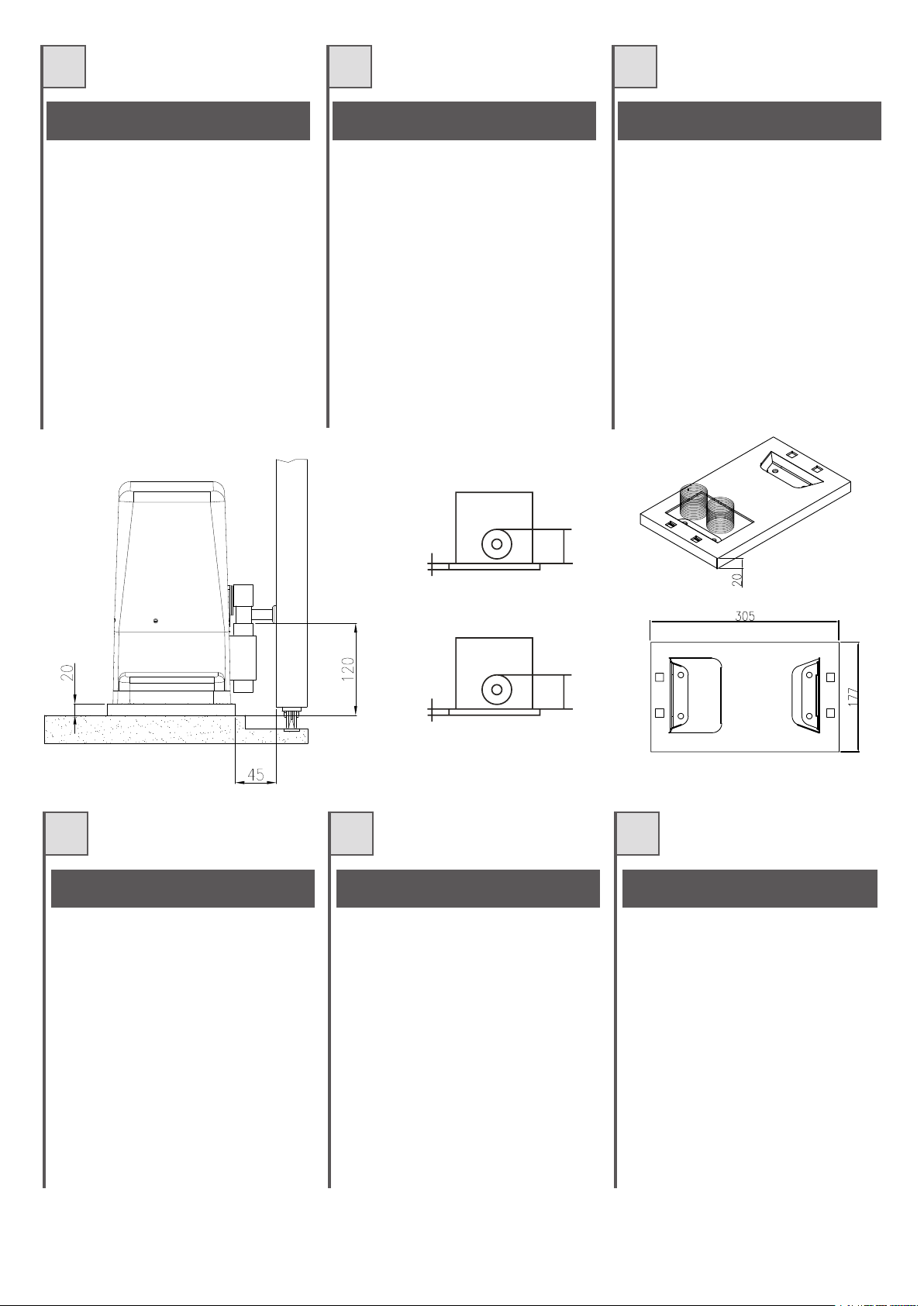
SBLOCCAGGIO DEL MOTORIDUTTORE
Per sbloccareilmotoriduttore inserire egirare la
chiave, tirare poi la leva dello sportellino come
indicatoinfig.6e7
DÉBLOCAGE DE L'OPÉRATEUR
Pour débrayer l'opérateur, introduire et tourner
la clé, tirer ensuite le levier de la porte comme
l'indiquelafig.6et7.
DESBLOQUEO DEL MOTORREDUCTOR
Para desbloquearelmotorreductor introduzca y
gire lallave, tire luegola palanca dela puerta tal
comoseindicaenlasfig.6y7.
Fig. 6 - Abb. 6
GB
GEARMOTOR RELEASE
In order to release the gearmotor, insert and
turn the key,then pull theleverof the coverflap
asindicatedinfigures6and7.
Fig. 7 - Abb. 7
D NL
ENTRIEGELN DES ANTRIEBS
Zum Entriegeln des Antriebs, den Schlüssel
einstecken und drehen, dann den Hebel an der
Lukedrehen,wieindenAbb.6und7gezeigt.
ONTGRENDELING VAN DE
REDUCTIEMOTOR
Voor het ontgrendelen van de reductiemotor
dient u desleutelinhet slot te stekenendieom
te draaien, vervolgens aan de hendel van het
luikje te trekken zoals dat op afb. 6 en 7 is
aangegeven.
9
Page 10
I
MONTAGGIO CREMAGLIERA MONTAGE CRÉMAILLÈRE MONTAJE DE LACREMALLERA
F
E
Portareilcancelloincompletaapertura.
Sistemare il motoriduttoresulla piastra fissatain
precedenza mediante le apposite viti in
dotazione.
Regolare i grani di regolazione in altezza (vedi
particolare B di fig. 10) in modo che il
motoriduttore sialzidi circa4mmdalla piastradi
fissaggio.
Appoggiare un elemento di cremagliera al
pignone, e fissare lo stesso con viti e distanziali
alcancello.
Spostare manualmente il cancello portando il
pignone in corrispondenza dell'ultimo
distanziale.
Fissare l'elemento di cremagliera
definitivamente.
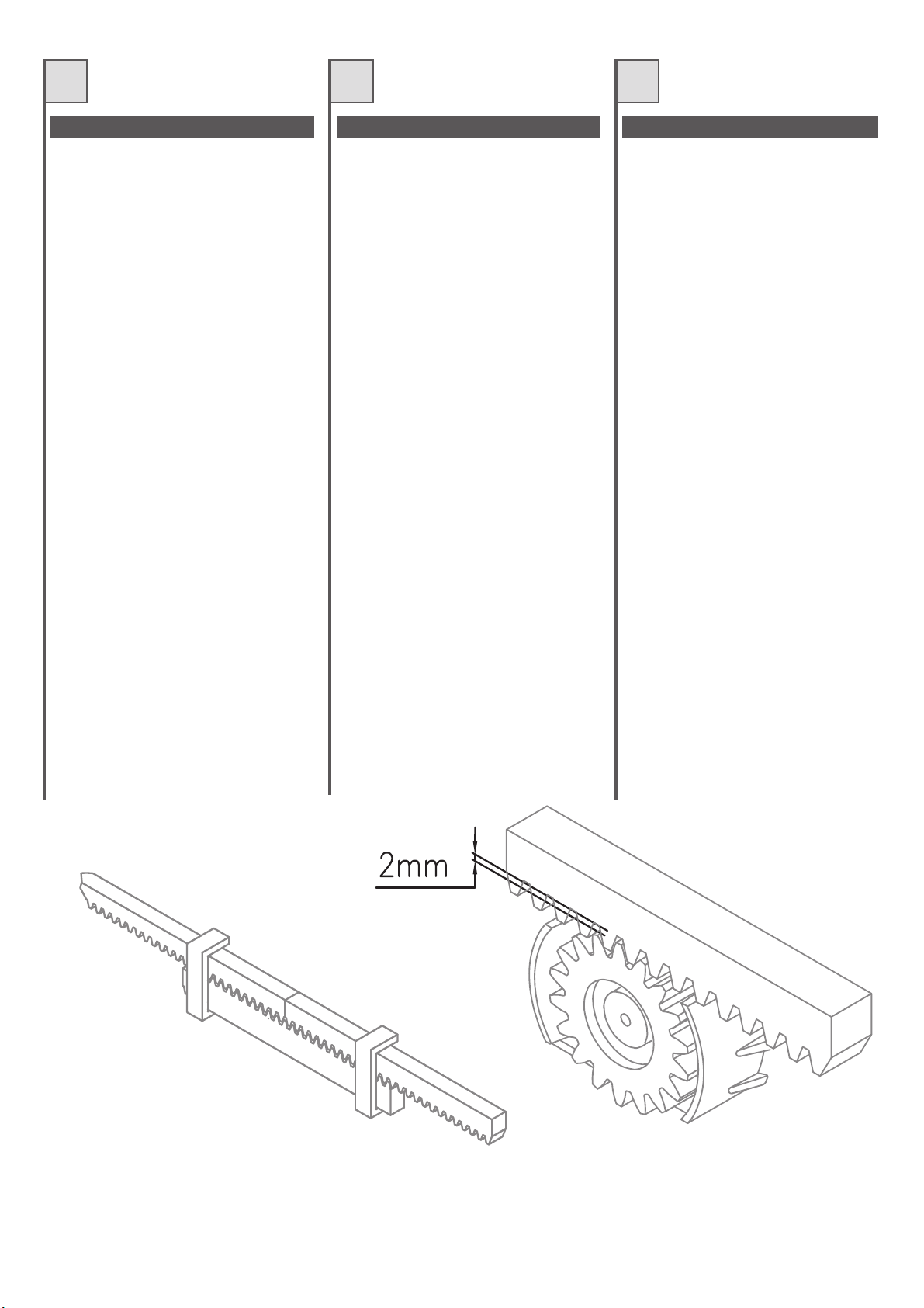
Per un corretto posizionamento degli altri
elementi e garantire la loro rettilineità, è
necessario utilizzare un elemento di
cremagliera usandolo come appoggio e
riferimento(Fig.8).
Si deve garantire un'aria fra cremagliera e
pignone di 2mm così danon far gravare il peso
del cancello sul pignone del motoriduttore (vedi
fig 9). Per far questo agire nei grani di
regolazionedelmotoriduttore(part.Bdifig.10).
N.B.
Nel caso di cancelli nuovi verificare in tempi
successivi all'installazione il gioco fra
cremagliera e pignone, se necessario agire nei
grani di regolazione oppure sulle asole della
cremaglieraperregistrareigiochi
Mettreleportailenouverturecomplète.
Placer l'opérateur sur la plaque précédemment
fixéeaveclesvisfournies.
Régler les goujons de réglage en hauteur (voir
détail B- fig.10) de manièreque l'opérateursoit
soulevé d'environ 4 mm par rapport à la plaque
defixation.
Appuyer un élément de crémaillère sur le
pignon, et lefixeravecdesvis et desentretoises
auportail.
Déplacer manuellement le portail en mettant le
pignonauniveaudeladernièreentretoise.
Fixerdéfinitivementl'élémentdecrémaillère.
Pour un positionnement correct des autres
éléments et pour qu'ils soient bien rectilignes, il
faututiliserun élément de crémaillère qui servira
d'appuietderepère(Fig.8).
Il faut garantir un espace de 2 mm entre la
crémaillère etle pignon demanière quele poids
du portail ne porte pas sur le pignon de
l'opérateur (voir fig. 9). Pour cela, agir sur les
goujons de réglagede l'opérateur (détailB - fig.
10).
N.B.
Dans le cas de portails neufs, vérifier après
l'installation le jeu entre la crémaillère et le
pignon, si nécessaire agir sur les goujons de
réglage ou sur les fentes de la crémaillère pour
réglerlesjeux.
Coloque la cancela en posición de apertura
completa.
Sitúe el motorreductor sobre la placa fijada
anteriormente mediante los tornillos
correspondientessuministrados.
Regule los bulones de centrajederegulaciónen
altura(véasedetalleBdelafig.10) deformaque
elmotorreductorselevanteaproximadamente4
mmdelaplacadefijación.
Apoye un elemento de cremallera al piñón y
fíjelocontornillosydistanciadoresalacancela.
Desplace manualmente la cancela situando el
piñón en el punto que coincide con el último
distanciador.
Fijeel elementode cremalleradefinitivamente.
Para conseguir un emplazamiento correcto de
losdemáselementosy garantizarsu rectitud,es
necesario utilizar un elemento de cremallera
usándolo como punto de apoyoy de referencia
(Fig.8).
Se tiene que garantizar un espacio entre la
cremallera yel piñón de2 mm paraevitar que el
peso de la cancela no descanse sobre el piñón
del motorreductor (véase fig 9). Para ello
accione los bulones de centraje de regulación
delmotorreductor (part.B dela fig.10).
N.B.
Cuando se trata de cancelas nuevas,
compruebe sucesivamente a la instalación el
juego entre la cremallera y el piñón, en caso
necesario accione los bulones de centraje de
regulación o las ranuras de la cremallera para
reglarlos juegos.
Fig. 8 - Abb. 8 Fig. 9 - Abb. 9
10
Page 11

GB
RACK ASSEMBLY MONTAGE DER ZAHNSTANGE MONTAGE TANDHEUGEL
D
NL
Openthegatefully.
Place the gearmotor on the plate that was
previouslysecuredwiththesuppliedscrews.
Regulate the height adjustment dowels (see
detail B in Fig. 10) so that the gearmotor lifts
fromtheplatebyabout4mm.
Place a rack element on the pinion and fix it to
thegatewithscrewsandspacers.
Manually move the gate and position the pinion
incorrespondencewiththelastspacer.
Permanentlyfixtherack.
In order to correctly position the other parts and
guarantee their alignment, a rack section must
beusedasasupportandreference(Fig.8).
A 2 mm gap must be maintained between the
rack and the pinion so as not to overload the
weight of thegate onthe pinion of thegearmotor
(see fig. 9). This is done through the regulation
of the gearmotor's adjustment dowels (detail B
offig.10).
N.B.
After the installation of new gates, every so
often, check the play between the rack and the
pinion; if necessary adjust the play by means of
the adjustment dowels or by means of the slots
oftherack.
DasTorganz öffnen.
Den Antrieb auf der vorher mit den
mitgelieferten Schrauben befestigten Platte
anbringen.
Die Verstellstifte in der Höhe regulieren (siehe
Detail B in Abb. 10), so dasssich derAntrieb ca.
4mmvonderAnkerplatte hebt.
Ein Zahnstangenelement auf das Ritzel legen
und dieses mit Schrauben und Distanzstücken
amTorbefestigen.
Das Tor von Hand verschieben, bis sich das
RitzelamletztenDistanzstückbefindet.
DasZahnstangenelementendgültigbefestigen.
Um die anderen Elemente korrekt anzubringen
und ihre Geradlinigkeit zugewährleisten, muss
ein Zahnstangenelement als Stütze und
Bezugnahmebenutztwerden(Abb.8).
Zwischen Zahnstange und Ritzel muss ein
Spiel von 2 mm garantiert sein, damit das
Torgewicht nicht auf dem Ritzel des Antriebs
lastet (siehe Abb. 9). Hierzu sind die
Verstellstifte des Antriebs zu betätigen(Detail B
inAbb. 10).
N.B.
Im Fall neuer Tore muss das Spiel zwischen
Zahnstange und Ritzel nach der Installation
kontrolliert werden; ggf. die Verstellstifte oder
die Schlitze der Zahnstange betätigen, um das
Spielzuregulieren.
Zetdepoorthelemaalopen.
Breng de reductiemotor met behulp van de
speciale meegeleverde schroeven op de
reedseerderbevestigdeplaataan.
Stel de stelstiften zodanig in de hoogte (zie
detail B op afb. 10) af dat de reductiemotor
ongeveer circa 4mm boven de
bevestigingsplaatkomttestaan.
Laat een element van de tandheugel op het
rondsel rusten en bevestig dit met schroeven
enafstandsstukkenopdepoort.
Verplaats de poort handmatig en breng het
rondselbijhetlaatsteafstandsstuk.
Bevestighettandheugelelementdefinitief.
Vooreen correcte positioneringvan de andere
elementen en garanderen dat ze opéén rechte
lijn liggen, dient u een tandheugelelement als
steunenreferentietegebruiken(afb.8).
U dient een ruimte tussen de tandheugel en
het rondselvan 2 mmaan te houdenzodat het
gewicht van de poortniet op hetrondsel vande
reductiemotor komt te rusten (zie afb. 9).
Hiervoor gebruikt u de stelstiften van de
reductiemotor(deelBopafb.10).
N.B.
In het geval van nieuwe poorten dient u na
verloop vantijd na installatie despeling tussen
tandheugel en rondsel te controleren; gebruik
zo nodig de stelstiften of de schuifopeningen
van de tandheugel om de spelingen af te
stellen.
Fig. 10 - Abb. 10
11
Page 12
I
FISSAGGIO DEL MOTORIDUTTORE FIXATION DE L'OPÉRATEUR FIJACIÓN DEL MOTORREDUCTOR
F
E
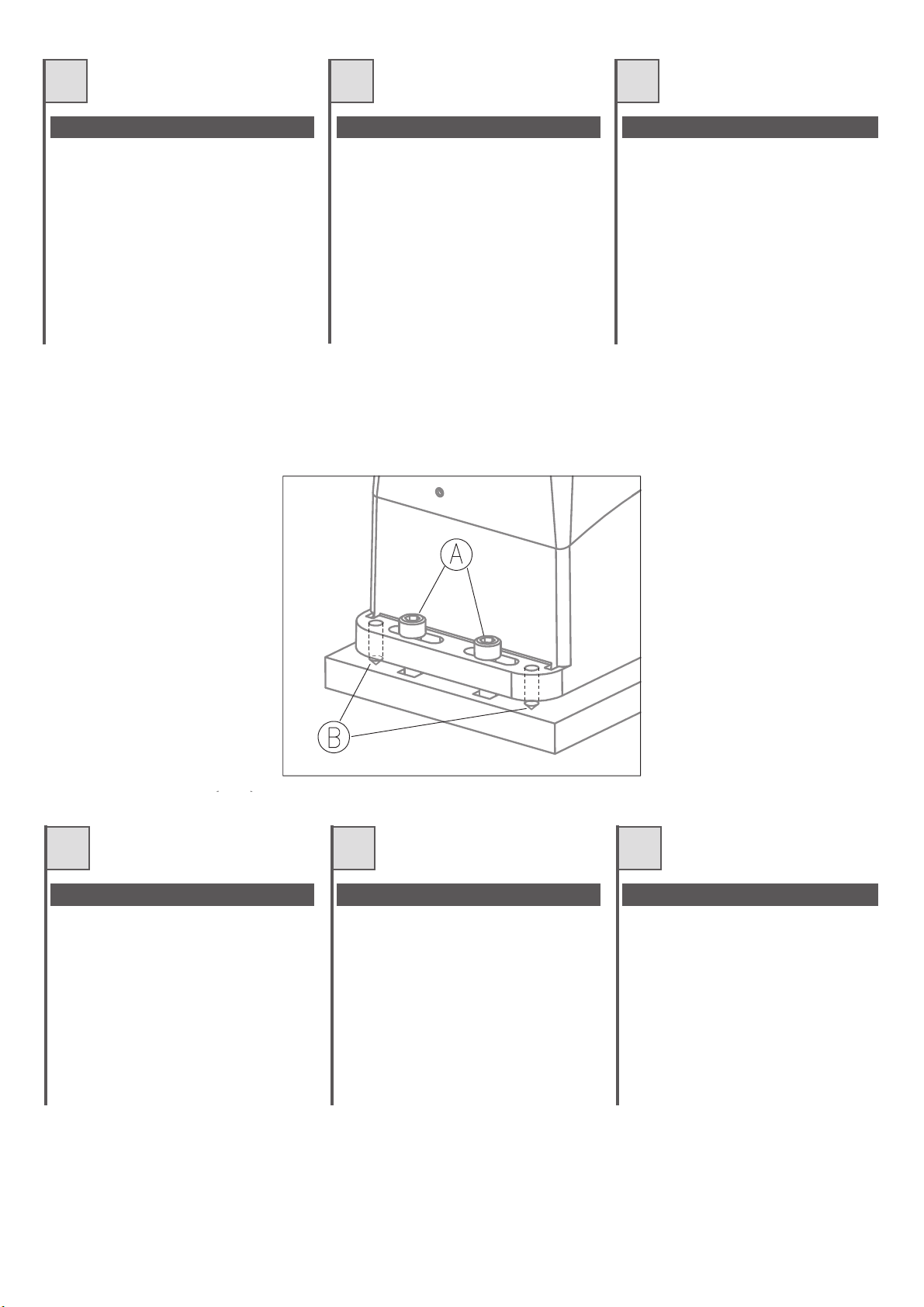
Appoggiare il motoriduttore sulla piastra
precedentemente fissata al basamento,
avvitare le4 viti A vedi fig10. Primadi avvitare a
fondo le4 vitiA, èpossibile regolare ladistanza
del motore dalla cremagliera agendo nei grani
B indicati sempre in fig. 10. In seguito è
importante bloccare energicamente le 4 viti A.
assicurandosi che durante tutta la corsa del
cancello,ilmotoriduttoresiabensaldoaterra.
Poser l'opérateur sur la plaque précédemment
fixée à la base, visser les 4 vis A (voir fig. 10).
Avant de visser à fondles 4 visA, il est possible
de régler la distance du moteur par rapport à la
crémaillère en agissant sur les goujons B
indiqués euxaussi dansla fig. 10. Ensuite, il est
importer de serrer à fond les 4 vis A, en
contrôlant que durant toute la course du portail,
l'opérateurestbienfixéausol.
Apoye el motorreductor sobre la placa
precedentemente fijada a la bancada, atornille
los 4 tornillos A (véase la fig 10). Antes de
atornillar a fondo los 4 tornillos A, es posible
regular la distancia del motor de la cremallera
accionandolosbulonesdecentraje B indicados
siempre en la fig. 10. A continuación es
importante bloquear enérgicamente los 4
tornillosA asegurándose de quedurante todo el
recorrido de la cancela el motorreductor se
encuentrebiensujetoalsuelo.
Fig. 10 - Abb. 10
GB
FIXING OF THE GEARMOTOR
Place the gearmotor onto the plate that was
previously fixed to the base and tighten the 4
bolts A (see fig. 10). The distance of the
gearmotor from the rack can be adjusted by
means of the dowels B illustrated in Fig. 10,
before fully tighteningthe fourbolts A.After this
has been done, the 4 bolts A must be fully
tightened, making sure that the gearmotor is
firmly securedto theground while the gateis in
motion.
D NL
BEFESTIGUNG DES ANTRIEBS
Den Antrieb auf der vorher am Fundament
befestigten Platte mit den 4 Schrauben A
befestigen – siehe Abb. 10. Bevor die 4
Schrauben A festgezogen werden, kann der
Abstand zwischen Antrieb und Zahnstange
durch Betätigung der Stifte, angegeben in Abb.
10, reguliert werden.Wichtig: die 4 SchraubenA
danach energisch festziehen und sicherstellen,
dass der Antrieb während des Torlaufs fest mit
demBodenverankertbleibt.
BEVESTIGING VAN DE REDUCTIEMOTOR
Zet de reductiemotor op de plaat die u
daarvoor op de grondplaat hebt bevestigd,
draai de 4 schroeven A van afb. 10 aan.
Voordat u de 4 schroeven A helemaal vast
draait, is het mogelijk de afstand van demotor
ten opzichte van de tandheugel af te stellen,
waarvoor u de stiften B op afb. 10. gebruikt.
Vervolgensis het van belangde 4 schroevenA
stevig vast te draaien waarbij u zich ervan
dient te vergewissen dat de reductiemotor
over de gehele loop van de poort goed vast zit
opdegrond.ne.
12
Page 13

I
F
E
ARERRACEDNIFESRUOCEDNIFASROCENIF
Nelle versioni con centralina incorporata, i
motoriduttori sono dotati di finecorsa elettronici
(FCEVO) mentre le versioni senza centralina
elettronica montano dei finecorsa meccanici
(FCM).
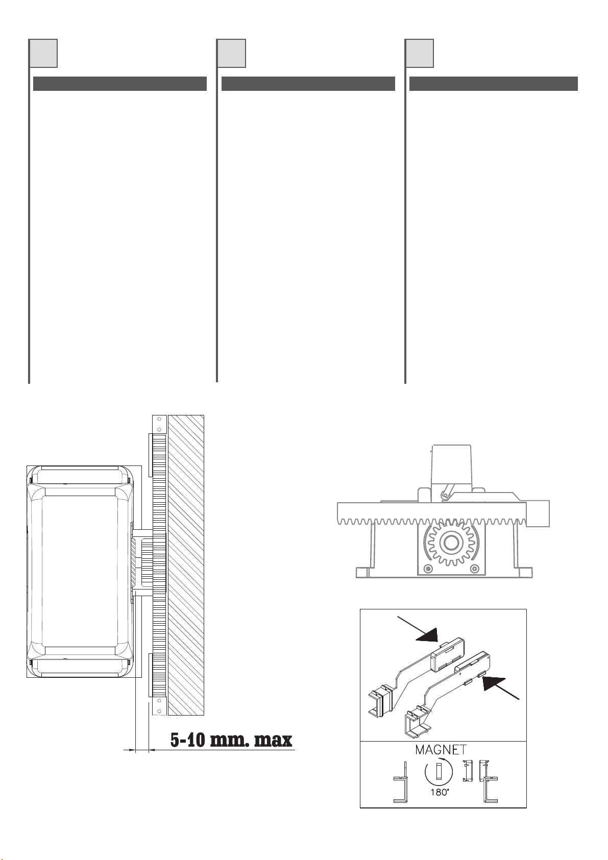
- Nel FCEVO fare attenzione che ciascuna
staffa con i magneti sia sufficientemente
vicina a finecorsa elettronico in modo da
garantire lo stop del motore.
tenere tra magnete ed FCEVO deve essere
compresafrai5ei10mm.(vedi fig11)
Verificare, avvicinando le 2 staffe di finecorsa
che i magneti si attraggano. Altrimenti, togliere
la copertura di plastica ed invertire il lato
d'appoggio di uno dei 2 magneti. Fig.11a.
CollegamentiFCEVO
Giallo
(alimentazione24V)
Marrone
Verde/Bianco
- Nel Finecorsa meccanico FCM verificare che
(negativoecomunefinecorsa)
(contattifinecorsa)
la corsa della molla sulla staffa avvenga
correttamente senza impedimenti. Per piccoli
aggiustamenti intervenire sullastaffa. (vedifig.
12)
La distanza da
Dans les versions avec logique de commande
incorporée, les opérateurssont munisde fins de
course électroniques (FCEVO) tandis que les
versions sans logique de commande ont des
finsdecoursemécaniques(FCM).
- Dans le FCEVO, faire attention que chaque
patte de support des aimants se trouve
suffisamment près du fin de course
électronique de manière à garantir l'arrêt du
moteur.
l'aiman
entre5et10mm. (voirfig. 11)
Approcher les 2 supports de fin de course et
s'assurer que les aimants s'attirent. Dans le
cas contraire, enlever la couverture en
plastique et inverser le côté d'appui d'un des
deux aimants. Fig.11a.
ConnexionsFCEVO
Jaune
Marron
Vert/Blanc
- Dans le fin de course mécanique FCM vérifier
que la course du ressort sur la patte s'effectue
correctement sans obstacles. Pour les petites
mises au point, intervenir sur la patte. (voirfig.
12)
La distance à maintenir entre
t le FCEVO doit être comprise
te
(alimentation24V)
(négatifetcommunfindecourse)
(contactsfindecourse)
En las versionescon centralina incorporada, los
motorreductores están equipados con fines
de carrera electrónicos (FCEVO) mientras las
versiones sin central electrónica montan fines
decarreramecánicos(FCM).
- En el FCEVO controle que cada una de las
abrazaderas con los magnetos se encuentre
suficientemente cercana al fin de carrera
electrónico de forma que garantice el freno
del motor.
mantener entre el magneto y el FCEVO
tiene que estar comprendida entre los 5 y
los10mm.(véasefig. 11)
Verificar acercando los dos estribos de fin de
carrera que los imanes se atraigan. De otro
modo, sacar la cobertura de plástico y invertir
el lado de apoyo de uno de los dos imanes.
Fig.11a.
ConexionesFCEVO
Amarillo
Marrón
Verde/Blanco
- En el fin de carrera mecánico FCM
compruebe que el recorrido del muelle sobre
la abrazadera se lleve a cabo correctamente
sin obstáculos. Para pequeños ajustes
accionelaabrazadera.(véasefig.12)
La distancia que es necesario
(alimentación24V)
(negativoycomúndelfindecarrera)
(contactosdelfindecarrera)
Fig. 11 - Abb. 11
Fig. 12 - Abb. 12
Fig. 11a - Abb. 11a
13
Page 14
GB
D
NL
SRAALEKAHCSDNIERETLAHCSDNEPOTSDNAHCTIWSTIMIL
For versions with incorporated control unit, the
gearmotors are equipped with electronic limit
switches (FCEVO) while versions without the
electronic control unit are fittedwith mechanical
stops(FCM).
- Make sure that on the FCEVO version, each
bracket with magnets is sufficiently close to
the electronic limit switch in order to
guarantee that the motorstops.
between the magnets and the FCEVO
mustbebetween5and 10mm (seefig. 11).
Bring near the limit brackets and be sure about
the magnets attraction. Otherwise, take the
plastic cover off and reverse the magnet surface
placed on the bracket. Fig.11a.
FCEVOconnections
Yellow
(power24V)
Brown
(limitswitchcommonandnegative)
Green/White
- For mechanical stops (FCM), make sure that
the travel of the spring on the bracket occurs
without difficulty. Adjust the bracket for slight
corrections(seefig.12).
(limitswitchcontacts)
The distance
Die Ausführungen mit eingebauter Steuerung
verfügen über elektronische Endschalter
(FCEVO), wogegen jene ohne elektronische
Steuerung mit mechanischen Endschaltern
(FCM)ausgestattetsind.
- Am FCEVO ist zu beachten, dass jeder Bügel
mit den Magneten ausreichend nah am
elektronischen Endschalterangebracht ist,um
das Anhalten desAntriebs zu garantieren.
Abstand zwischen Magnet und FCEVO
muss zwischen 5 und 10 mm sein (siehe
Abb.11)
Die 2 Endschalterbügel nähern und sicher sein
dass sich die 2 Magnete anziehen. Ansonsten die
Plastikabdeckung abnehmen und die Stützseite
von einen der Magneten umdrehen.
ANSCHLÜSSEDESFCEVO
gelb
(24VVersorgung)
braun
(Minus und gemeinsamer Leiter des
Endschalters)
grün/weiß
- Am mechanischen Endschalter FCM prüfen,
dass sich die Feder am Bügel korrekt und
hindernisfrei bewegt. Kleine Justierungen
können am Bügel ausgeführt werden (siehe
Abb.12)
(Endschalterkontakte)
Abb.11a.
Der
n de uitvoeringen met funderingsplaat zijn de
I
reductiemotoren met elektronische
eindschakelaars (FCEVO) toegerust, terwijl
op de uitvoeringen zonder elektronische
besturingseenheid mechanische
eindaanslagen(FCM)wordengemonteerd.
- Bij de FCEVO dient u erop te letten dat elke
beugel met de magneten zich dicht genoeg
bij de elektronische eindschakelaar bevindt
om hetstoppen van demotor te waarborgen.
De afstand die moet worden
aangehouden tussen magneet en FCEVO
moet tussen de 5 en 10 mm liggen. (zie
afb.11)
Breng beide beugels naar elkaar en voel of de
magneten elkaar aantrekken. Indien dit niet het
geval is; open een van de plastic houders op de
beugel en draai de magneet om. Afb.11a.
AansluitingenFCEVO
Geel
(stroomvoorziening24V)
Bruin
eindschakelaar)
Groen/Wit
- Bij demechanische eindaanslag FCM dientu
(min en gemeenschappelijk
(contacteneindschakelaar)
te controleren dat de veer correct zonder
belemmeringen op de beugel kan lopen.
Kleine correcties voert uop debeugel uit. (zie
afb.12)
14
Fig. 12 - Abb. 12
Fig. 11 - Abb. 11
Fig. 11a - Abb11a
Page 15

I
EF
COLLEGAMENTI ELETTRICI BRANCHEMENTS ÉLECTRIQUES
EVO600/EVO800/EVO1200
Per questi motoriduttori con centralina
elettronica incorporata, alcuni cablaggi sono
già effettuati. Completare i cablaggi rimanenti
seguendo le istruzioni della centralina in
dotazione.
ACE500ET – ACE800E
Per questi motoriduttori con centralina
elettronica incorporata, alcuni cablaggi sono
già effettuati. Completare i cablaggi rimanenti
seguendo le istruzioni della centralina in
dotazione. Collegare un cavo di sezione
almeno 3x1.5mmq, per l’alimentazione 230Vac
nella morsettiera indicata dalla figura 13.
EVO600SC (senza centralina)
Per i motoriduttori senza centralina a bordo,
effettuare i collegamenti sulla morsettiera
come in figura 14.
Per alimentare il motoriduttore dalla centralina
elettronica, usare un cavo di sezione 4x1,5
mmq. Per collegare i finecorsa del motoriduttore
alla centralina elettronica, usare un cavo di
sezione 3x0,5 mmq. Vedere anche le istruzioni
della centralina in dotazione.
* NOTA: il collegamento dei finecorsa FCC e
FCA dipende dal lato su cui viene installato il
motoriduttore e quindi dal lato di apertura del
cancello. Consigliamo di effettuare alcune
prove manuali prima di procedere con la
programmazione della centralina.
EVO600/EVO800/EVO1200
Pour ces opérateurs avec logique de commande
électronique incorporée, certains câblages sont
déjà effectués. Compléter les câblages restants
en suivant les instructions de la logique de
commande fournie.
ACE500ET – ACE800E
Pour ces opérateurs avec logique de commande
électronique incorporée, certains câblages sont
déjà effectués. Compléter les câblages restants en
suivant les instructions de la logique de commande
fournie. Connecter un câble ayant une section
minimum de 3 x 1,5 mm², pour l’alimentation 230
Vca dans le bornier indiqué sur la figure 13.
EVO600SC (sans logique de commande)
Pour les opérateurs sans logique de commande
incorporée, effectuer les branchements sur le
bornier comme sur la figure 14.
Pour alimenter l’opérateur par l’intermédiaire
de la logique électronique, utiliser un câble de
section 4 x 1,5 mm². Pour connecter les fins de
course de l’opérateur à la logique électronique,
utiliser un câble de section 3 x 0,5 mm². Voir
aussi les instructions de la logique fournie.
* NOTE : la connexion des fins de course FCC
et FCA dépend du côté sur lequel l’opérateur est
installé et donc du côté d’ouverture du portail.
Nous conseillons d’effectuer quelques essais
manuels avant de procéder à la programmation
de la logique.
CONEXIONES ELÉCTRICAS
EVO600/EVO800/EVO1200
Para estos motorreductores con centralita
electrónica incorporada, algunos cables ya
están pasados. Pase los cables restantes
siguiendo las instrucciones de la centralita
entregada.
ACE500ET – ACE800E
Para estos motorreductores con centralita
electrónica incorporada, algunos cables ya
están pasados. Pase los cables restantes
siguiendo las instrucciones de la centralita
entregada. Conecte un cable de sección mínima
3x1,5 mm2, para la alimentación de 230Vac, en
la regleta que se muestra en la figura 13.
EVO600SC (sin centralita)
Para los motorreductores sin centralita
incorporada, realice las conexiones en la
regleta que se muestra en la figura 14.
Para alimentar el motorreductor de la centralita
electrónica, utilice un cable de sección 4x1,5
mm2. Para conectar los fines de carrera del
motorreductor a la centralita electrónica, utilice
un cable de sección 3x0,5 mm2. Véanse
también las instrucciones de la centralita
suministrada.
* NOTA: la conexión de los fines de carrera
FCC y FCA depende del lado en que se instala
el motorreductor y del lado de apertura de la
cancela. Se aconseja realizar algunas pruebas
manuales antes de programar la centralita.
ENCODER
Nei motori con centrale a bordo, l’encoder è già
pre-cablato. Nei motori senza centrale effettuare
il cablaggio utilizzando un cavo schermato di
sezione almeno 3x0.25mmq.
E’ opportuno che il cavo non superi la lunghezza
di 10 metri.
COLLEGARE:
- cavo BLU al morsetto ENC1 - della centralina
(alimentazione).
- cavo VERDE al morsetto ENC1 + della
centralina (alimentazione).
- cavo BIANCO al morsetto ENC1 D della
centralina (ingresso segnale).
ENCODEUR
Dans les moteurs avec logique incorporée,
l’encodeur est déjà pré-câblé. Dans les moteurs
sans logique incorporée, procéder au câblage
en utilisant un câble blindé avec une section
d’au moins 3 x 0,25 mm².
Il est préférable que le câble ne dépasse pas
10 mètres de longueur.
CONNECTER :
- câble BLEU à la borne ENC1 - de la logique
(alimentation).
- câble VERT à la borne ENC1 + de la logique
(alimentation).
- câble BLANC à la borne ENC1 D de la logique
(entrée signal).
ENCODER
En los motores con central incorporada, el
encoder ya está cableado. En los motores sin
central, pase los cables utilizando un cable
blindado de sección mínima 3x0,25 mm2.
Es oportuno que el cable no mida más de 10
metros de longitud.
CONECTAR:
- cable AZUL al borne ENC1 - de la centralita
(alimentación).
- cable VERDE al borne ENC1 + de la centralita
(alimentación).
- cable BLANCO al borne ENC1 D de la
centralita (entrada señal).
15
Page 16

GB
ELECTRICAL CONNECTIONS ELEKTRISCHE ANSCHLÜSSE ELEKTRISCHE AANSLUITINGEN
D
NL
EVO600/EVO800/EVO1200
On these gearmotors with built-in electronic
control unit, some wiring is already connected.
Complete the remaining wiring according to the
instructions of the control unit supplied.
ACE500ET – ACE800E
On these gearmotors with built-in electronic
control unit, some wiring is already connected.
Complete the remaining wiring according to the
instructions of the control unit supplied. Connect
a cable with a section of at least 3x1.5mm2, for
the 230Vac power supply on the terminal board
as shown in figure 13.
EVO600SC (without control unit)
For gearmotors without built-in control unit,
make the connections on the terminal board as
shown in figure 14.
To power the gearmotor from the electronic
control unit, use a cable with a section of 4x1,5
mm2. To connect the gearmotor limit switch
to the electronic control unit, use a cable with
a section of 3x0,5 mm2. Refer also to the
instructions of the control unit supplied.
* NOTE: connection of the limit switches FCC
and FCA depends on the side on which the
gearmotor is installed and therefore on the
gate opening side. Run a number of manual
tests before proceeding with control unit
programming.
ENCODER
The encoder is pre-wired on motors with control
unit incorporated. On motors without control
unit, wire using a shielded cable with a section
of at least 3x0.25mm2.
Cable lengths should not exceed 10 metres.
CONNECT:
- BLUE wire to terminal ENC1 – of the control
unit (power supply).
- GREEN wire to terminal ENC1 – of the control
unit (power supply).
- WHITE wire to terminal ENC1 D of the control
unit (signal input).
EVO600/EVO800/EVO1200
An diesen Antrieben mit eingebauter elektronischer
Steuerung sind einige Verkabelungen bereits ausgeführt.
Die restlichen Verkabelungen nach den Anweisungen
der mitgelieferten Steuerung vervollständigen.
ACE500ET – ACE800E
An diesen Antrieben mit eingebauter elektronischer
Steuerung sind einige Verkabelungen bereits
ausgeführt. Die restlichen Verkabelungen nach
den Anweisungen der mitgelieferten Steuerung
vervollständigen. Für die 230 Vac Versorgung
ein Kabel mit einem Querschnitt von mindestens
3x1,5 mm2 an der auf Abbildung 13 gezeigten
Klemmleiste anschließen.
EVO600SC (ohne Steuerung)
Für die Antriebe ohne eingebaute Steuerung
die Anschlüsse wie auf Abbildung 14 gezeigt
auf der Klemmleiste vornehmen.
Zur Versorgung des Antrieb über die Steuerung
ein Kabel mit einem Querschnitt von 4x1,5 mm2
verwenden. Für den Anschluss der Endschalter
des Antriebs an die elektronische Steuerung
ein Kabel mit einem Querschnitt von 3x0,5
mm2 verwenden. Siehe auch die Anleitungen
für die mitgelieferte Steuerung.
*ANMERKUNG: Der Anschluss für die
Endschalter FCC und FCA hängt davon ab,
auf welcher Seite der Antrieb installiert wird
und folglich davon, nach welcher Seite sich das
Tor öffnet. Es empfiehlt sich, manuell einige
Tests durchzuführen, bevor die Steuerung
programmiert wird.
ENCODER
Bei den Antrieben mit eingebauter Steuerung
ist der Encoder bereits vorverkabelt. Bei den
Motoren ohne Steuerung erfolgt die Verkabelung
über ein geschirmtes Kabel mit einem Querschnitt
von mindestens 3x0,25 mm2.
Es empfiehlt sich, ein Kabel mit einer Länge
von max. 10 m zu verwenden.
FOLGENDE ANSCHLÜSSE VORNEHMEN:
- BLAUES Kabel an Klemme ENC1 - der
Steuerung (Versorgung).
- GRÜNES Kabel an Klemme ENC1 + der
Steuerung (Versorgung).
- WEISSES Kabel an Klemme ENC1 D der
Steuerung (Signaleingang).
EVO600/EVO800/EVO1200
Voor deze reductiemotoren met ingebouwde
elektronische besturingseenheid zijn sommige
bekabelingen al uitgevoerd. Completeer de
overige bekabeling volgens de aanwijzingen
van de meegeleverde besturingseenheid.
ACE500ET – ACE800E
Voor deze reductiemotoren met ingebouwde
elektronische zijn sommige bekabelingen al
uitgevoerd. Completeer de overige bekabeling
volgens de aanwijzingen van de meegeleverde
besturingseenheid. Sluit een kabel met een
doorsnede van tenminste 3x1,5mm2 voor
230Vac-stroomvoorziening aan op de op
afbeelding 13 weergegeven klemmenstrip.
EVO600SC (zonder besturingseenheid)
Voor de reductiemotoren zonder ingebouwde
besturingseenheid dient u de aansluitingen
op de klemmenstrip uit te voeren zoals op
afbeelding 14 te zien is.
Voor de stroomvoorziening van de elektronische
besturingseenheid dient u een kabel met een
doorsnede van 4x1,5 mm2 te gebruiken. Om
de eindschakelaars van de reductiemotor op
de elektronische besturingseenheid aan te
sluiten dient u een kabel met een doorsnede
van 3x0,5 mm2 te gebruiken. Raadpleeg
ook de aanwijzingen van de meegeleverde
besturingseenheid.
* N.B.: de aansluiting van de eindschakelaars
FCC en FCA is afhankelijk van de kant waar
de reductiemotor wordt geïnstalleerd en dus
van de kant van opening van de poort. Het
is raadzaam enkele handmatige tests uit te
voeren voordat u de besturingseenheid gaat
programmeren.
ENCODER
Bij motoren met ingebouwde besturingseenheid
is de encoder reeds voorbekabeld. Bij motoren
zonder besturingseenheid dient u de bekabeling
uit te voeren met een afgeschermde kabel met
een doorsnede van tenminste 3x0,25mm2.
Het is van belang dat de kabel niet langer dan
10 meter is.
AANSLUITING:
- BLAUWE kabel op de klem ENC1 - van de
besturingseenheid (stroomvoorziening).
- GROENE kabel op de klem ENC1 + van de
besturingseenheid (stroomvoorziening).
- WITTE kabel op de klem ENC1 D van de
besturingseenheid (ingang signaal).
16
Page 17

ACE500ET - ACE800E
Fig. 13 - Abb. 13
EVO...SC
Fig. 14 - Abb. 14
17
Page 18

I
MESSA IN FUNZIONE MISE EN MARCHE PUESTAEN FUNCIONAMIENTO
F
E
Dopo aver eseguito l'installazione e i
collegamenti elettrici effettuare il collaudo
dell'impianto seguendo le indicazioni riportate
nelleistruzionidella centralina elettronica:
- autoapprendimentodella corsadel cancello
- autoapprendimentodei varitelecomandi
- verifica del funzionamento dei vari accessori
disicurezza.
Encoder
elettronica Telcoma sono provvisti di encoder
per la rilevazione degli ostacoli. Secondo la
normativa EN 12445 ogni automazione deve
superare le prove d'impatto misurate con
l'appositostrumento.
Eseguire quindi le prove di impatto e variare la
coppia del motore agendo sul trimmer di
regolazione presente sulla centralina (vedi
istruzionicentralina)
Se questonon fosse sufficiente perrientrare nel
grafico indicato dalle normative consigliamo di
installare
un profiloin gommamorbida in testa al cancello
inmododaattutirel'impatto.
Se regolando la coppiadel motoree montandoil
profilo in gomma non si riesce ancora a
soddisfare la normativa è obbligatorio montare
dei dispositivi alternativi ad esempio una costa
sensibilesulbordomobile
delcancello.
: i modelli completi di centralina
Après avoir effectué l'installation et les
connexions électriques, procéder à l'essai de
l'installation suivant les indications reportées
dans la logique de commande électronique,
c'est-à-dire:
- auto-apprentissagede lacourse duportail
- auto-apprentissage des différentes
télécommandes
- contrôle du fonctionnement des différents
accessoiresdesécurité.
Encodeur:
électronique Telcoma sont munis d'encodeur
pour la détection des obstacles. D'après la
norme EN 12445, chaque automatisme doit
surmonter les tests d'impact mesurés avec
l'instrumentspécial.
Effectuer par conséquent les tests d'impact et
modifier le couple du moteur en agissant sur le
trimmer de réglage présent sur la logique de
commande(voirlesinstructionsdelalogique)
Si celane suffit paspour rentrer dans les limites
du graphique indiqué par les normes, nous
conseillons d'installer un profilé en caoutchouc
souple sur latête duportail de manière àamortir
l'impact.
Si le réglagedu coupledu moteurou lemontage
d'un profiléen caoutchouc nesuffisent pas pour
satisfaire les normes, il faut monter des
dispositifs alternatifs par exemple une barre
palpeusesurlebordmobileduportail.
les modèles équipés de logique
Después de llevar a cabo la instalación y las
conexiones eléctricas, efectúe la prueba de la
estructura siguiendo las indicaciones que
aparecenenlacentralelectrónica,esdecir:
- autoaprendizajedel recorridode lacancela
- autoaprendizajede losdiversos telemandos
- verificación del funcionamiento de los
diversosaccesoriosdeseguridad.
Encoder:
electrónica Telcoma disponen de un encoder
para la detección de los obstáculos. Según la
normativa EN12445 cada automatización tiene
que superar las pruebas de impacto medidas
conelinstrumentocorrespondiente.
Lleve a cabopor lotanto laspruebas deimpacto
y modifique el par del motor accionando el
trimmer de regulación que se encuentra
presente en la central (véaseinstrucciones de la
central).
Si esto no fuera suficiente para situarse dentro
de los valores del gráfico indicado por las
normativas, le aconsejamos queinstale un perfil
de goma blanda al inicio de lacancela de forma
queamortigüeelimpacto.
Si regulando el par del motor y montando el
perfil de goma no consigue satisfacer tampoco
la normativa, se verá obligado a montar
dispositivos alternativos como por ejemplo una
bandadetectoraenelbordemóvildelacancela.
los modelos equipados con la central
18
Page 19

GB
D
NL
START-UP INBETRIEBSETZUNG
After having performed the installation and
electrical connections, test the system by
following the indications illustrated in the
electroniccontrolunit,instruction:
- Self-recognitionof thegate's travel
- Self-recognition of the various remote
controls
- Functionaltest ofthe varioussafety devices.
Encoder:
electronic controlunit includean encoder forthe
detection of obstacles. In accordance with the
EN 12445 standard, each automation system
must pass the system test appraised with the
appropriateinstrument.
Perform the system test and alter the torque of
the motor by meansof thetrimmer onthe control
unit(seecontrolunitinstructions).
If this is insufficient in order to fall within the
graph indicated by the standard, we advise to
install a soft rubberprofile onthe leadingedge of
thegateinordertosoftentheimpact.
If the standard can still not be satisfied after the
motor torque has been adjusted and a rubber
profile fitted, then an alternative device must be
installed such asa sensitiveedge onthe leading
edgeofthegate.
models including the Telcoma
Nachdem die Installation und die elektrischen
Anschlüsse ausgeführt sind, muss die Anlage
nach den Anweisungen in der elektronischen
Steuerungabgenommenwerden,inklusive:
- Selbsterlernungdes Torlaufs
- Selbsterlernung der verschiedenen
Fernbedienungen
- Betriebstest der verschiedenen
Sicherheitsvorrichtungen.
Encoder:
Steuerung ausgestatteten Antriebe verfügen
über Encoder zur Wahrnehmung der
Hindernisse. Gemäß der Vorschrift EN 12445
muss die Aufprallkraft jeder Automatisierung
miteinemspeziellenInstrumentgeprüftwerden.
Daher die Aufprallkraftprüfungen mit Änderung
desMotordrehmoments durchführen, indem der
Trimmer an der Steuerung betätigt wird (siehe
dieAnweisungen derSteuerung).
Sollten die gemessenen Werte nicht mit den laut
Norm angegebenenübereinstimmen, empfehlen
wir, ein Profil aus weichem Gummi an die
Kopfseitedes Torszu montieren,um denAufprall
zudämpfen.
Sollten die Werte der Aufprallkraft auch nach
der Regulierung des Motordrehmoments und
der Montage des Gummiprofils nicht den
Werten der Norm entsprechen, müssen
alternative Vorrichtungen installiert werden,wie
zum Beispiel eine Schaltleiste an der
beweglichenTorkante.
die mit elektronischer Telcoma
INBEDRIJFSTELLING
Na de installatie en de elektrische
aansluitingen verricht te hebben dient u de
eindtest van de installatie volgens de
aanwijzingen van de elektronische
besturingseenheid uit te voeren, dat wil
zeggen:
- zelfleringvan deloop vande poort
- zelflering van de verschillende
afstandsbedieningen
- controle van de werking van de
verschillendeveiligheidsinrichtingen.
Encoder:
besturingseenheid Telcoma zijn uitgerust met
een encoder voor obstakeldetectie . Volgens
de norm EN 12445 moet elke automatisering
de impacttests met het daarvoor bestemde
instrument.
Voer daarna de impacttests uit en wijzig het
motorkoppel met behulp van de steltrimmer
die zich op de besturingseenheid bevindt (zie
aanwijzingenbesturingseenheid)
Mocht dit niet voldoende zijn om de waarden
binnen de in de voorschriften aangegeven
grafiek te laten komen, dan is het raadzaam
een lijst van zacht rubber aan de kop van de
poort aan te brengen om de impact te
verzachten.
Wanneerhet na afstelling van hetmotorkoppel
en montage van de rubber lijst het nog niet
mogelijk is aan de voorschriften te voldoen is
het verplicht alternatieve inrichtingen aan te
brengen zoals bijvoorbeeld een contactlijst op
debewegenderandvandepoort.
de modellen met een elektronische
19
Page 20

I
OLIO MOTORE HUILE MOTEUR ACEITE MOTOR
F
E
Vite di sfiato: Una volta eseguita l'installazione
allentarela vitedisfiato indicatainfigura 15part.B.
Per i modelli a bagno d'olio controllare il livello
almenounavoltaall'anno.
Per controllare il livello dell'olio, operare come
segue:
1.Toglieretensione all'impianto.
2.Togliereil coperchiodel motoriduttore.
3.Togliereil tappoolio (part.Adi fig15).
4. Verificare visivamente che l'olio sia a livello
dell'avvolgimento(circamm20daltappo).
Se necessario, rabboccare con olio TS 20 o
TS40(dipendedalmodellodimotoriduttore).
Nota per EVO1200: Con temperatuire
inferiori a -10°C, consigliamo di sostituire l’olio
contenuto nel motore EVO1200 con il nostro
olio tipo TS20, oppure in alternativa, usare il
nostro riscaldatore HOT .
Vis de purge: Après avoir effectué l'installation,
desserrerlavisdepurge(détailB-fig.15).
Pour les modèles en bain d'huile, contrôler le
niveauaumoinsunefoisparan.
Pour contrôler le niveau de l'huile, procéder de
lafaçonsuivante:
1.Couperlatensiondel'installation.
2.Enleverlecouvercledel'opérateur.
3. Enlever le bouchon de l'huile (détail A fig. 15).
4. Vérifier visuellement que l'huile arrive au
niveau du bobinage (environ 20 mm du
bouchon).
Si nécessaire, rajouter de l'huileTS 20 ou TS40
(suivantlemodèled'opérateur).
Note pour EVO1200: à des températures
inférieures à -10°C, nous conseillons de
remplacer l’huile contenue dans le moteur
EVO1200 par notre huile type TS20, ou en
alternative, d’utiliser notre réchauffeur HOT.
Tornillode purga: Después de llevar a cabo la
instalación, afloje el tornillo de purga que se
indicaenlafigura15part.B.
Paralosmodelosconbañodeaceite,controleel
nivelporlomenosunavezalaño.
Para controlar el nivel del aceite, efectúe lo
siguiente:
1. saquelatensióndelaestructura;
2. saquela tapa del motorreductor;
3. saqueel tapón del aceite (part.Ade lafig. 15);
4. compruebe visualmente que el aceite se
encuentre en el nivel del bobinado
(aproximadamentea20mmdeltapón).
En caso necesario, acabe de llenar con aceite
TS 20 o TS40 (depende del modelo de
motorreductor).
Nota para EVO1200: Con temperaturas
inferiores a -10°C se aconseja cambiar el
aceite del motor EVO1200 con nuestro aceite
tipo TS20 o, como alternativa, utilizar nuestro
calentador HOT .
20
Fig. 15 - Abb. 15
Page 21

GB
MOTOR OIL MOTORÖL MOTOROLIE
D
NL
Bleed screw: Once installation has been
completed, slackenthe bleed screw indicatedin
figure15detailB.
In the oil bath models, the oil level should be
checkedatleastonceayear.
1. Disconnect the power supply from the
system.
2. Removethe gearmotor cover.
3. Removethe oil plug (detailAof fig15).
4. Visually check thatthe oil is at thelevel of the
coil(approx.20mmfromthecap).
If necessary, top up with TS 20 or TS40 oil
(dependingonthemodelofthegearmotor).
Note for EVO1200: With temperatures below
-10°C we recommend replacing the oil in the
EVO1200 motor with our oil type TS20, or
alternatively to use our heater model HOT.
Entlüfterschraube: Nachdem die Installation
ausgeführt ist, die Entlüfterschraube Detail B,
Abb.15lockern.
Für die Modelle in Ölbad muss der Ölstand
mindestenseinmalproJahrkontrolliertwerden.
Für die Ölstandkontrolle ist wie folgend
beschriebenvorzugehen:
1.Die Spannung zurAnlage abschalten.
2.DenDeckeldesAntriebs abnehmen.
3.DenÖlstopfenabnehmen(DetailA,Abb. 15).
4. Visuell überprüfen, dass sich das Öl an der
Wicklungbefindet(ca.20mmvomStopfen).
Ggf. mit Öl TS 20 oder TS40 nachfüllen (hängt
vomModelldesAntriebs ab).
Anmerkung für EVO1200: Bei Temperaturen
unter -10°C empfehlen wir, das im Motor
EVO1200 enthaltene Öl durch unser Öl Typ
TS20 zu ersetzen oder alternativ dazu unser
Heizgerät HOT zu verwenden.
Ontluchtingsschroef: Wanneer de installatie
ten einde is draait u de ontluchtingsschroef op
afbeelding15deel.Blos.
Voorde modellenmet oliebad controleert u het
peiltenminsteéénmaalperjaar.
Ga als volgt te werk om het oliepeil te
controleren:
1.Haaldespanningvandeinstallatie.
2.Haaldedekplaatvandereductiemotorweg.
3.Haaldeoliedop(deelAop afb.15) weg.
4. Controleer of de olie een zodanig peil staat
dat de motor geheel onder staat (ongeveer
20mmonderdedop).
Vul zo nodig bij met olie TS 20 of TS40
(afhankelijkvanhetmodelreductiemotor).
Opmerking voor EVO1200: Bij temperaturen
van minder dan -10°C is het raadzaam in plaats
van de in de motor EVO1200 aanwezige olie de
motor met onze olie type TS20 te vullen of ons
verwarmingselement HOT te gebruiken
Fig. 15 - Abb. 15
21
Page 22
I
ANOMALIE E RIMEDI ANOMALIES ET REMÈDES ANOMALÍAS Y SOLUCIONES
F
E
1. Il cancello non apre o non chiude. Il motore
elettrico non funziona e non si avverte
alcunrumore o vibrazione.
- Verificare che la centralina elettronica sia
regolarmentealimentata.
- Verificarel'efficienzadei fusibili.
- Verificare, con l'ausilio di adeguati strumenti
diagnostici, che le funzioni della centralina
elettronicasianocorrette.
- Accertarsi che il motoriduttore riceva
alimentazione230Vca±10%.
2. Il cancello non apre, si avvertono
vibrazioni oppure il motore funziona ma
nonavvieneilmovimento.
- Verificare l'efficienza del condensatore di
avviamento motore. Per controllare questa
condizione collegare un condensatore
volante da 20 F in parallelo alle fasi del
motore.
- Verificare che il pignone dentato sia in presa
conlacremagliera.
- Controllare che il motoriduttore non sia in
posizionemanuale(sbloccato).
- verificare che il cancello non sia bloccato
meccanicamente ad uno dei due arresti
meccanici.
In tal caso bisogna sbloccare manualmente il
motore, azionare ilcancello a mano, liberandolo
dalla posizione anomalae, primadi ripristinare il
funzionamento automatico, provvedere ad un
correttoposizionamentodelfinecorsa
μ
1. Le portail ne s'ouvre pas ou ne se ferme
pas. Le moteur électrique ne fonctionne
pas et on n'entend donc aucun bruit ou
vibration.
- Vérifier que la logique de commande
électroniqueestrégulièrementalimentée.
- Vérifier l'efficacitédes fusibles.
- Vérifier, à l'aide d'instruments diagnostics
adéquats, que les fonctions de la logique de
commandeélectroniquesontcorrecte.
- S'assurer que l'opérateur est alimenté à 230
Vca±10%.
2. Le portail ne s'ouvre pas, on sent des
vibrations ou bien le moteur fonctionne
maisiln'yapasdemouvement.
- Vérifier l'efficacité du condensateur de
démarrage moteur. Pour contrôler cette
condition connecter un condensateur volant
μ
de20 Fenparallèleauxphasesdumoteur.
- Vérifier que le pignon denté est en prise avec
lacrémaillère.
- Contrôler quel'opérateur n'est pas enposition
manuelle(débloqué).
- Vérifier que leportail n'estpas bloquésur l'une
desdeuxbutéesmécaniques.
Dans ce cas, il faut débrayer manuellement le
moteur, actionner le portail à la main en le
libérant de la position anormale et, avant de
rétablir le fonctionnement automatique,
repositionnercorrectementlefindecourse
1. La cancela no se abre o no se cierra. El
motor eléctrico no funciona y no se
advierte, por lo tanto, ningún ruido o
vibración.
- Compruebe que la central electrónica esté
alimentadadeformaregular.
- Compruebela funcionalidadde losfusibles.
- Compruebe, con la ayuda de los
instrumentos diagnósticos adecuados, que
las funciones de la central electrónica son
correctas.
- Asegúrese de que el motorreductor recibe
alimentaciónde230Vca±10%.
2. La cancela no se abre, se advierten
vibracioneso el motor funciona pero no se
produceelmovimiento.
- Compruebela funcionalidaddel condensador
de puesta en marcha del motor. Para
controlar esta condición conecte un
condensador volante de 20 F en paralelo a
lasfasesdelmotor.
- Compruebe que el piñón dentado se
encuentreenganchadoconlacremallera.
- Controle que el motorreductor no se
encuentre en posición manual
(desbloqueado).
- Compruebe que la cancela no esté
bloqueada mecánicamenteen unode los dos
topesmecánicos.
En ese caso, es necesario desbloquear
manualmente el motor, accionar la cancela a
mano, liberándola de la posición anómala y,
antes de restablecer el funcionamiento
automático, ocuparse decolocar correctamente
elfindecarrera.
μ
22
Page 23

GB
D
NL
TROUBLE SHOOTING
1. The gate doesn't open or close. The
electric motor doesn't work and therefore
nonoiseorvibrationisheard.
- Check that the control unit is correctly
suppliedwithpower.
- Checkthat thefuses areintact.
- With the aid of appropriate diagnostics
instruments, check that the electronic control
unitfunctionsarecorrect.
- Makesure that a230Vac± 10%power supply
isbeingfeedtothegearmotor.
2. The gate doesn't open, vibrations occur or
themotorrunsbutnomovementoccurs.
- Check that the motor's starting capacitor is
working correctly. To do so, connect a 20 F
capacitor in parallel to the phases of the
motor.
- Checkthat thepinion isconnected to the rack.
- Check that thegearmotor isnot in themanual
position(released).
- Check that the gate is not mechanically
blockedtooneofthetwomechanicalstops.
If this is so, release the motor, manually
manoeuvre the gate, freeing it from the blocked
position and reposition the stopcorrectly before
resettingtheautomaticoperation.
μ
STÖRUNGEN UND ABHILFEN
1. Das Toröffnet und schließt sich nicht. Der
E-Motor funktioniert nicht und man
bemerkt daher weder ein Geräusch noch
Vibrationen.
- Prüfen, dass die elektronische Steuerung
ordnungsgemäßgespeistist.
- DieEffizienz derSicherungen überprüfen.
- Mit Hilfe geeigneter Diagnoseinstrumente
überprüfen, dass die Funktionen der
elektronischenSteuerungkorrektsind.
- Sicher stellen, dass der Antrieb mit einer
Spannungvon230Vca±10%gespeistist.
2. Das Tor öffnet sich nicht, man bemerkt
Vibrationen; oder der Antrieb funktioniert,
abereserfolgtkeineBewegung.
- Die Effizienz des Starterkondensators des
Antriebs überprüfen. Um dies zu
kontrollieren, einen 20 F Kondensator mit
den Phasen des Antriebs fliegend
parallelschalten.
- Prüfen, dass das gezahnte Ritzel an der
Zahnstangeeingreift.
- Prüfen, ob sich der Antrieb in Position
„entriegelt“(bzw.manuell) befindet.
- Prüfen, ob das Tor an einem der beiden
mechanischenAnschläge blockiertist.
Den Antrieb in diesem Fall entriegeln und das
Tor von Hand aus jener Stellung verschieben;
denEndschalterkorrekt positionieren, bevor der
automatischeBetriebdesTorsrückgestellt wird.
μ
ANOMALIEN EN REMEDIES
1. De poort gaat open noch dicht. De
elektromotor werkt niet en er wordt daarna
geenenkelgeluidoftrillingwaargenomen.
- Controleer of de elektronische
besturingseenheid naar behoren van stroom
voorzienwordt
- Controleerof dezekeringen goedwerken.
- Controleer met behulp van adequate
diagnose-instrumenten of de functies van de
elektronischebesturingseenheidcorrectzijn.
- Vergewisu ervan dat de stroomtoevoer van
dereductiemotor230Vca±10%is.
2. De poort gaat niet open, er worden
trillingen waargenomen of de motor werkt
wel,maardepoortkomtnietinbeweging.
- Controleer of de startcondensator van de
motor werkt. Om dit te controleren sluit een
condensator van 20 F in parallel op de
motorfasenaan.
- Ga na of het getande rondsel in de
tandheugelgrijpt.
- Controleer of de reductiemotor niet in
handbediendestandstaat(ontgrendeld).
- controleer of de poort niet mechanisch op
een van de twee mechanische stops
geblokkeerdstaat.
In dat gevalontgrendelt u handmatig demotor,
verplaatst u de poort handmatig, waarbiju hem
uit de abnormale positie haalt en, alvorens de
automatische bediening herstelt, de
eindaanslagcorrectpositioneert
μ
23
Page 24

IFE
AVVERTENZE IMPORTANTI
SULL'INSTALLAZIONE
1. L'installazione dell'automazione deve essere
eseguita a regola d'arte da personale qualificato
avente i requisiti di legge e fatta in conformità
della direttiva macchine 98/37/CE e alle
normativeEN13241-1, EN12453 eEN 12445.
2. Verificare la solidità delle strutture esistenti
(colonne, cerniere, ante) in relazione alle forze
sviluppatedal motore.
3. Verificare che vi siano dei fermi meccanici di
adeguata robustezza a fine apertura e fine
chiusuradelle ante.
4. Verificare lo stato di eventuali cavi già presenti
nell'impianto.
5. Fare un'analisi dei rischi dell'automazione e di
conseguenza adottare le sicurezze e le
segnalazioninecessarie.
6. Installare i comandi (ad esempio il selettore a
chiave) in modo che l'utilizzatore non si trovi in
unazona pericolosa.
7. Terminata l'installazione provare più volte i
dispositivi disicurezza, segnalazionee di sblocco
dell'automazione.
8. Applicare sull'automazione l'etichetta o la
targhetta CE contenentile informazionidi pericolo
ei datidi identificazione.
9. Consegnare all'utilizzatore finale le istruzioni
d'uso, le avvertenze per la sicurezza e la
dichiarazioneCE diconformità.
10. Accertarsi che l'utilizzatore abbia compreso il
corretto funzionamento automatico, manuale e di
emergenzadell'automazione.
11. Informare l'utilizzatore per iscritto (ad esempio
nelleistruzioni d'uso):
a. dell'eventuale presenza di rischi residui non
protettie dell'usoimproprio prevedibile.
b. Di scollegare l'alimentazione quando viene
eseguita la pulizia nell'area dell'automazione
o viene fatta piccola manutenzione (es:
ridipingere).
c. Di controllare frequentemente che non vi
siano danni visibili all'automazione e nel caso
ve ne siano, avvertire immediatamente
l'installatore
d. Di non far giocare i bambini nelle immediate
vicinanzedell'automazione
12.Predisporre un piano di manutenzione
dell'impianto (almeno ogni 6 mesi) riportando su
diun appositoregistro gliinterventi eseguiti.
AVERTISSEMENTS IMPORTANTS
CONCERNANT L'INSTALLATION
11. L'installation de l'automation doit être effectuée
dans les règles de l'art par du personnel
spécialisé, conformément aux dispositions
légales, à la directive machine 98/37/CE et aux
normesEN 12453et EN12445.
2. S'assurer que les structures existantes
(colonnes, charnières, vantaux) soient
suffisamment solides pour résister aux forces
développéespar lemoteur.
3. S'assurer que les arrêts mécaniques en fin
d'ouverture et en fin de fermeture des vantaux
soientsuffisamment robustes.
4. Vérifier l'état des câbles qui se trouvent
éventuellementdéjà dansl'installation
5. Faire une analyse des risques de l'automation et
adopter, enfonction de celle-ci, les dispositifs de
sécuritéet designalisation nécessaires.
6. Installer les commandes (par exemple le
sélecteur à clé) de manière à ce que l'utilisateur
nese trouvepas dansune zone dangereuse.
7. Une fois l'installation terminée, tester plusieurs
fois les dispositifs de sécurité, de signalisation et
dedéverrouillage del'automation.
8. Appliquer sur l'automation l'étiquette oula plaque
CE où sont indiqués les dangers présentés par
l'automation ainsi que les données
d'identificationde lamachine.
9. Remettre à l'utilisateur final le moded'emploi, les
avertissements concernant la sécurité et la
déclarationCE deconformité.
10. S'assurer que l'utilisateur a bien compris le
fonctionnement automatique, manuel et
d'urgencede l'automation.
11. Informerl'utilisateur par écrit(par exempledans le
moded'emploi) :
a. dela présenceéventuelle derisques résiduels
non protégés et de l'usage impropre
prévisible.
b. De la nécessité de couper l'alimentation
quand le nettoyage de la zone de
l'automatisme a lieu ou en cas de petites
interventionsde maintenance(ex. repeindre).
c. De la nécessité de contrôler fréquemment
l'absence de dommages visibles à
l'automatisme et s'il y en a, avertir
immédiatementl'installateur.
d. Qu'il ne faut pas laisser les enfants jouer à
proximitéde l'automatisme.
12. Etablir un plan de maintenance de l'installation
(au moins tous les 6 mois) en inscrivant sur un
registre prévu à cet effet les interventions
effectuées.
ADVERTENCIAS IMPORTANTES
SOBRE LA INSTALACION
1. La instalación del automatismo debe ser
realizada según los cánones, por personal
cualificado que reúnalos requisitos establecidos
por laley y de conformidadcon la Directivasobre
máquinas 98/37/CE ycon lasnormas EN12453 y
EN12445.
2. Compruebe la solidez de las estructuras
existentes (columnas, bisagras, hojas) en
relación con las fuerzas desarrolladas por el
motor.
3. Controle que haya retenes mecánicos de solidez
adecuada en los puntos de finde aperturay defin
decierre delas hojas.
4. Controle el estado de los cables ya existentes en
lainstalación, ensu caso.
5. Haga unanálisis delos riesgosdel automatismoy
adopte los dispositivos de seguridad y las
señalizacionesnecesarias enconsecuencia.
6. Instale los mandos (por ejemplo, el selector de
llave) de manera que el usuario no se encuentre
enuna zonapeligrosa.
7. Terminada la instalación,pruebe varias veces los
dispositivos de seguridad, señalización y
desbloqueodel automatismo.
8. Aplique en el automatismo una etiqueta o una
placa CE que contenga las informaciones de
peligroy losdatos deidentificación.
9. Entregue al usuario finallas instrucciones para el
uso, las advertencias para la seguridad y la
declaraciónCE deconformidad.
10. Asegúrese de que el usuario haya comprendido
el correcto funcionamiento automático, manual y
deemergencia delautomatismo.
11. Informe al usuario por escrito (por ejemplo en las
instruccionesde uso):
a. sobre la presencia de riesgos residuales no
protegidos y sobre el uso inadecuado
previsible.
b. quedebe desconectarla alimentación cuando
hace la limpieza en la zona de la
automatización o si hace un pequeño
mantenimiento(ej.: pintar).
c. que debe controlar a menudo que la
automatización no presente daños visibles y,
en elcaso de quelos haya, deberá advertirde
inmediatoal instalador
d. queno debe permitirque losniños jueguen en
lascercanías dela automatización
12. Predisponga un programa de mantenimiento de
la instalación (almenos cada6 meses),anotando
en un registro expresamente dedicado las
intervencionesrealizadas.
SMALTIMENTO ELIMINATION ELIMINACION
Questo prodotto è formato da vari componenti che
potrebbero a loro volta contenere sostanze
inquinanti.Non disperderenell'ambiente!
Informarsi sulsistema diriciclaggio osmaltimento del
prodotto attenendosi alle norme di legge vigenti a
livellolocale.
24
Ce produit est constitué de divers composants qui
pourraient à leur tour contenir des substances
polluantes. Ne pas laisser ce produit gagner
l'environnement.
S'informer sur le système de recyclage ou
d'élimination du produit conformément aux
dispositions légalesen vigueurà unniveau local.
Este producto está constituido por varios
componentes que podrían, a su vez, contener
sustancias contaminantes. ¡No los vierta enel medio
ambiente!
Infórmese sobreel sistema dereciclaje o eliminación
del producto con arreglo a las leyes vigentes en
ámbitolocal.
Page 25

GB D NL
IMPORTANT RECOMMENDATIONS
CONCERNING INSTALLATION
1. Only qualified personnel having the legal
requirements must install the automation
according to the principles of good workmanship
and in conformity with the machinery directive
98/37/CE and standards EN 12453 and EN
12445.
2. Check that the existing structures (posts, hinges,
leaves) are stable in relation to the forces
developedby themotor.
3. Check that suitably robust limit stops have been
installedfor endof gateopening and closing.
4. Check the state of the cables that are already
presentin thesystem.
5. Analyse the hazards connected with the
automation system and adopt the necessary
safetyand signallingdevices accordingly.
6. Install the commands (e.g. the key selector) so
that the user is not placed in a hazardous area
whenusing them.
7. Upon completion of the installation, test the
safety, signalling and release devices of the
automationsystem severaltimes.
8. Apply the CE label or plate with information
regarding the hazards and identification data on
theautomation.
9. Give the end user the instructions for use, the
safety recommendations and the CE declaration
ofconformity.
10. Ensure that the user has understood the correct
automatic, manual and emergency operation of
theautomation system.
11. Inform the user in writing (in the use instructions
forexample):
a. Ofpossible non secludedresidual risks and of
foreseeableimproper use.
b. Todisconnect thepower supplywhen cleaning
the area that is automated or when performing
smallmaintenance operations(e.g.: repainting).
c. To frequently control that no visible damage
has occurred to the automation, andto inform the
installerimmediately ifdamage isnoticed.
d. Notto allowchildren to play inthe vicinityof the
automation.
12.Prepare a maintenance schedule for the
automation installation (at least once every 6
months), recording the work carried out in a
specialbook.
WICHTIGE
INSTALLATIONSHINWEISE
1. Die Installation der Automatisierung muss in
Übereinstimmung mit der Maschinenrichtlinie
98/37/EU undden Bestimmungen EN12453 undEN
12445, fachgerecht und von qualifiziertem Personal,
das die gesetzlichen Anforderungen erfüllt,
vorgenommen werden.
2. Die Stabilität der vorhandenen Strukturen (Säulen,
Scharniere, Flügel) im Hinblick auf die vom Motor
entwickelten Kräfteüberprüfen.
3. Sicherstellen, dass am Öffnungsanschlag und am
Schließanschlag der Torflügel ausreichend robuste
mechanische Feststellvorrichtungen vorhanden
sind.
4. Den Zustand eventueller, bereits in der Anlage
vorhandener Kabelüberprüfen.
5. Die Risiken,die durch dieAutomatisierung entstehen
können, abwägen und dementsprechende
Sicherheitsvorkehrungen treffen, sowie die
erforderlichen Warnhinweise anbringen.
6. Die Steuerungen (z.B. Schlüsselschalter) so
installieren, dass sich der Benutzer nicht in einem
Gefahrenbereich aufhaltenmuss.
7. Nach abgeschlossener Installation mehrmals die
Sicherheits-, Anzeige- und Entsperrvorrichtungen
derAutomatisierung erproben.
8. Auf der Automatisierung die EU- Etikette oder das
EU-Schild anbringen,auf dem dieGefahrenhinweise
und dieKenndaten aufgeführtsind.
9. Dem Endkunden die Bedienungsanweisung, die
Sicherheitshinweise und die EUKonformitätserklärung aushändigen.
10. Sicherstellen, dass der Bediener die korrekte
automatische und manuelle Funktionsweise sowie
den NotbetriebderAutomatisierung verstanden hat.
11. Den Benutzer schriftlich (z.B. in den
Bedienungsanleitungen) über folgendes
informieren:
a. eventuelles Vorhandensein nicht geschützter
Restrisiken; vorhersehbarer unsachgemäßer
Gebrauch
b. Vorschrift, die Stromversorgung abzutrennen,
wenn im Bereich der Automatisierung gereinigt
wird oder kleine Instandhaltungen ausgeführt
werden (wiez.B. neuerAnstrich)
c. dass er die Automatisierung häufig auf sichtbare
Schäden zu überprüfen und ggf. unverzüglich
den Installateurzu benachrichtigenhat
d. dass Kinder nicht in der unmittelbaren Nähe der
Automatisierung spielendürfen.
12. Einen Wartungsplan für die Anlage vorbereiten
(müssen mindestens alle 6 Monate) und die
ausgeführten Wartungseingriffe in einem
entsprechenden Verzeichnis anmerken.
BELANGRIJKE AANWIJZINGEN
M.B.T. DE INSTALLATIE
1. De installatie van de automatisering moet op
deugdelijke wijze uitgevoerd worden door
vakmensen die aan de wettelijke eisen voldoen en
moet in overeenstemming zijn met de
Machinerichtlijn 98/37/EG en de normen EN 12453
en EN12445.
2. Er moet gecontroleerd worden of de bestaande
constructie-elementen (zuilen, scharnieren,
vleugels) stevig zijn met het oog op de kracht die
door demotor ontwikkeldwordt.
3. Er moet gecontroleerd worden of er aan het einde
van de opening en aan het einde van de sluitingvan
de vleugels mechanische stops zijn die stevig
genoeg zijn.
4. Controleer de staat van de kabels die eventueel
reeds inde installatieaanwezig zijn.
5. Er moet een risicoanalyse van de automatisering
gemaakt worden en op basis daarvan moeten de
nodige veiligheids- en waarschuwingssystemen
toegepast worden.
6. De bedieningselementen (bijv.de sleutelschakelaar)
moeten zodanig geïnstalleerd worden dat de
gebruiker zichniet opgevaarlijke plaatsen bevindt.
7. Na afloop van de installatie moeten de veiligheids-,
waarschuwings- en ontgrendelsystemen van de
automatisering diversekeren getestworden.
8. Op de automatisering moet het CE-etiket of het CEplaatje met informatie over de gevaren en de
typegegevens aangebrachtworden.
9. De gebruiksaanwijzing, de veiligheidsvoorschriften
en de EG-verklaring van overeenstemming moeten
aan deeindgebruiker gegevenworden.
10. Er moet nagegaan worden of de gebruiker de juiste
automatische, handbediende en noodwerking van
de automatiseringbegrepen heeft.
11. Informeer de gebruiker schriftelijk (bijvoorbeeld in de
aanwijzingen voor gebruik) ten aanzien van het
volgende:
a. eventueel nog aanwezige niet-beveiligde
restrisico's envoorspelbaar oneigenlijkgebruik.
b. de stroomtoevoer los te koppelen wanneer er
schoonmaakwerkzaamheden inde zonerondom
de automatisering worden verricht of klein
onderhoud (bijvoorbeeld:schilderwerk).
c. dikwijls te controleren dat er geen zichtbare
schade aan deautomatisering is, en indiendie er
is, onmiddellijkde installateurte waarschuwen
d. geen kinderen in de onmiddellijke nabijheid van
de automatiseringte latenspelen
12. Er moet een onderhoudsplan van de installatie
opgesteld worden (minimaal om de 6 maanden)
waarbij de uitgevoerde werkzaamheden in een
speciaal registergenoteerd moetenworden.
DISPOSAL ENTSORGUNG VERWIJDERING
This product is made up of various components that
couldcontain pollutants.Dispose ofproperly!
Make enquiries concerning the recycling or disposal
ofthe product,complying withthe local lawsin force.
Dieses Produkt besteht aus verschiedenen
Bauteilen, die ihrerseitsdie Umwelt verschmutzende
Stoffeenthalten können.Sachgerecht entsorgen!
Informieren Sie sich, nach welchem Recycling- oder
Entsorgungssystem das Produkt entsprechend der
örtlichgeltenden Bestimmungenzu entsorgenist
Dit product bestaat uit diverse onderdelen die ook
weer verontreinigende stoffen kunnen bevatten. Het
productmag nietzomaar weggegooidworden!
Informeer over dewijze van hergebruik of verwijdering
van het product en neem daarbij de wettelijke
voorschriften dieter plaatsegelden inacht.
25
Page 26

AUTOMATISMI PROFESSIONALI PER CANCELLI E GARAGE
PROFESSIONAL GARAGE DOOR AND GATE OPERATORS
Il fabbricante:
Telcoma srl
Via L. Manzoni, 11 - 31015 - Z.I. Campidui
Conegliano (TV) - ITALY
DICHIARA che il prodotto
MOTORIDUTTORE
“Serie EVO e ACE500ET - ACE800E”
è conforme alle condizioni delle seguenti direttive CEE:
· Direttive 73/23 CEE Direttiva 93/68 CEE
Bassa Tensione
· Direttiva 89/336 CEE Direttiva 92/31 CEE
Direttiva 92/31 CEE compatibilità Elettromagnetica
e che:
sono state applicate le seguenti (parti/clausole) di norme
armonizzate:
EN60335-1, EN 60204-1, EN 61000-6-3, EN61000-6-1
e per le sole parti applicabili le norme
EN12445 e En12453
DICHIARAZIONE DEL FABBRICANTE
(Direttiva 98/37 CEE Allegato II, Parte B)
The manufacturer:
Telcoma srl
Via L. Manzoni, 11 - 31015 - Z.I. Campidui
Conegliano (TV) - ITALY
DECLARES that the products
GEAR MOTOR DRIVE UNIT
“Series EVO and ”
are conforming to the only applicable parts of this
directive;
Directive 92/31/EEC Electromagnetic Compatibility
The following parts/clauses of the harmonised regulations
EN60335-1, EN60204-1, EN 61000-6-3, EN61000-6-1
Directive 73/23/EEC, Directive 93/68/EEC
Directive 89/336/EEC, Directive 92/31/EEC
and for the only applicable parts the norms
EN12445 e EN12453
DECLARATION BY THE MANUFACTURER
(Directive 98/37/EEC, Attachment II, Part B)
ACE500ET - ACE800E
Low Voltage
have been applied:
Il prodotto è costruito per essere incorporato in una
macchina o per essere assemblato con altri macchinari
per costruire una macchina considerata dalla Direttiva
98/37 CEE
E inoltre dichiara che non è consentito mettere in servizio
il prodotto fino a che la macchina in cui saranno
incorporati o di cui diverranno componenti sia stata
identificata e ne sia stata dichiarata la conformità alle
condizioni della Direttiva 98/87 CEE e alla legislazione
nazionale che lo traspone, vale a dire fino a che il prodotto
di cui alla presente dichiarazione non formi un complesso
unico con la macchina finale.
Conegliano, lì 01/06/2006
Legale Rappresentante Legal Representative
Augusto Silvio Brunello Augusto Silvio Brunello
The product have been constructed to be incorporated in
a machine or to be assembled with other machinery to
construct a machine as set out in Directive 98/37/EEC
The manufacturer furthermore declares that it is not
permitted to operate the products until the machine in which
they will be incorporated or of which they will become
components has been identified and its conformity with the
provisions set out in Directive 98/37/EEC and the national
legislation has been declared, i.e. until the products as set
forth in this declaration form a single unit with the final
machine.
Conegliano, lì 01/06/2006
262728
Page 27

Page 28

Page 29

FCM20R
29
Page 30

CERTIFICATO DI GARANZIA
PRODOTTO
TIMBRO E/O FIRMA DELL’INSTALLATORE
DATA D’INSTALLAZIONE
%
IFE
GARANZIA GARANTIE GARANTÍA
La presentegaranzia copre gli eventualiguasti e/oanomalie
dovuti a difetti e/ovizi di fabbricazione. La garanzia decade
automaticamente in caso di manomissione o errato utilizzo
delprodotto.
Durante ilperiodo digaranzia laditta Telcomasrl si impegna
a riparare e/o sostituire leparti difettate e non manomesse.
Restano a intero ed esclusivo carico del cliente il diritto di
chiamata, nonché le spese di rimozione,imballo e trasporto
delprodotto perla riparazionee sostituzione.
Cette garantie couvre les éventuelles pannes et/ou
anomalies imputables à des défauts eou vis de fabrication.
La garantie s'annule automatiquement si le produit a été
modifiéou utiliséde maniéreimpropre. L'entrepriseTelcoma
srl s'engange, durant la periode de garantie du produit, à
reparer et/ou remplacer les piéces defectueuses n'ayant
pas subi de modifications. Restent entièrement et
exclusivament àla charge duclient, ledroit d'appelainsi que
les frais d'enleévement, d'emballage et de transport du
produitpour saréparation ousubstitution.
La presente garantía es válida en el caso cie averias y/o
anomaliás causadas por defectos y/o desperfectos de
fabricación. Lagarantía automáticamente pierdevalor en el
caso de arreglos improprios o utilizactión equivocada del
producto. Durante el periodo de garantía, la empresa
Telcoma srl se compromete a reparary/o cambiar la partes
defectuosas que no hayan sido dañadas. Quedan a total y
exclusivo cargo delcliente el derechode llamada, como asi
también los gastos de desmontaje, embalaje y transporte
delproducto parala raparacióno cambio.
GB D NL
WARRANTY GARANTIE GARANTIE
This warranty covers any failure and/or malfunctioning due
tomanifacturing faultsand/or badworkmanship.
The warranty is automatically invalidated if the product is
tamperedwith orused incorrectly.
During thewarranty period,Telcomasrl undertakesto repair
and/or replace faulty parts provided they have not been
tamperedwith.
The call-outcharge aswell asthe expensesfor disassembly
removal packing and transport of the product for repair or
replacementshall becharged entirelyto thecustomer.
Die vorliegendeGarantie deckteventuelle Defekteund/oder
Betriebsstörungen ab, die auf Fabricationsfehler
und/oder mängel zurück-zuführen sin. Die Garantie
verfällt automatisch im Falle von Manipulationen oder
fehlerhaftem Gebrauch des Produktes. Während der
Garantiezeit verpflichtet sich die Firma Telcoma srl, die
defekten und nicht manipulierten Teile zu reparieren
und/oder auszutauschen. Die Auforderung des
Kundendienstes als auch die Kosten für die Abholung, die
Verpackung und den Transport des Produkten für die
Reparatur bzw den Austausch gehen zu vollen und
ausschliefßlichenLasten desKunden.
Telcoma srl - Via L. Manzoni, 11 - Z.I. Campidui
31015 Conegliano - (TV) Italy - Tel. +39 0438-451099
Fax +39 0438-451102 - Part. IVA 00809520265
http://www.telcoma.it E-mail: info@telcoma .it
Deze garantie dekteventuele storingenen/of defectendie te
wijten aan fabrieksfouten en/of gebreken. De garantie
vervalt automatischindien de gebruikerzelf aanhet produkt
gesleuteld heeft of veranderingen aangebracht heeft of
indien hetprodukt op verkeerdewijze gebruiktis. Tijdensde
garantietermijn neemt de Firma Telcoma srl de verplichting
op te defecte onderdelen te repareren en/of te vervangen
mits de gebruiker deze onderdelen niet zelf geprobeerd
heeft te repareren. De voorrijkosten alsmede de onkosten
voor het demonteren, het verpakken en verzenden van het
produkt te repareren of te vervangen zijn en blijven
uitsluitendvoor rekeningvan deklant.
 Loading...