

Page 1
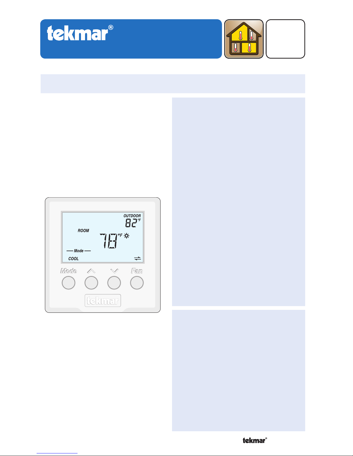
tekmarNet®4 Thermostat 540
Installation & Operation Manual
D540
08/10
Replaces:03/09
1 of 24 © 2010
D 540 - 08/10
Zoning
The tekmarNet®4 Thermostat 540
provides operation for:
One Stage Heat
One Stage Cool
One Stage Fan
•
•
•
Introduction
Features
Requires 7 wires (tN4, C, R, W,
Rc, Y, G)
Outdoor temperature display
Bright backlight
2 button temperature adjustment
Communication with other
tekmarNet® devices improves
system efficiency and comfort
Schedule member status enables
setback operation
Optimum start
Responds to tekmarNet® Scenes
Cooling Group Master
Freeze protection
Exercising
Zone synchronization
•
•
•
•
•
•
•
•
•
•
•
•
Benefi ts
Energy savings
Reduced temperature swings
Compatible with tekmarNet®
Timers, User Switches and
Gateway for additional control
Interlock prevents simultaneous
heating & cooling
•
•
•
•
Page 2

2 of 24© 2010 D 540 - 08/10
Congratulations on the purchase of your new tekmar thermostat.
This manual will step through the complete installation, programming and sequence
of operation for this control. At the back, there are tips for control and system
troubleshooting.
Getting Started
Preparation
tekmar or jeweller screwdriver
Phillips head screwdriver
•
•
Wire Stripper•
Tools Required
------------------------------------------------------
------------------------------------------------------
Materials Required
--------------------------------------------------
--------------------------------------------------
2, #6 x 1” Wood Screws
18 AWG LVT Solid Wire
(Low Voltage Connections)
•
•
Optional Adapter Plate 007 (for
installation on 2” x 4” gang box)
•
Installation
Table of Contents
Getting Started ..............................2
Installation .........................................2
Preparation ....................................2
Removing The Thermostat Base ...3
Mounting The Thermostat Base ....3
Thermostat Wiring .........................4
Testing the Thermostat Wiring ......5
Mounting the Thermostat ..............6
Cleaning the Thermostat ...............6
Switch Settings ..................................7
User Interface ....................................8
Display...........................................8
Symbols Description .....................8
Button Operation ...........................9
Settings ..................................10-15
Sequence of Operation ....................16
Heating Operation .......................16
Cooling Operation ....................... 17
Fan Operation .............................18
Schedules ...................................19
Scenes (System Override) ..........19
Troubleshooting ...............................20
Error Messages .................... 20-21
Frequently Asked Questions .......22
Job Record ..................................23
Technical Data .............................23
Limited Warranty and Product
Return Procedure ........................24
Caution
Improper installation and operation of this control could result in damage to the
equipment and possibly even personal injury or death. It is your responsibility
to ensure that this control is safely installed according to all applicable codes and
standards. This electronic control is not intended for use as a primary limit control.
Other controls that are intended and certified as safety limits must be placed into
the control circuit.
Page 3
3 of 24 © 2010 D 540 - 08/10
Choose the placement of the thermostats early in the construction process to
enable proper wiring during rough-in.
Consider the following:
Interior Wall.
Keep dry. Avoid potential leakage onto the control.
Relative Humidity max 92% up to 104°F (40°C), 50% RH above 104°F (40°C).
Non-condensing environment.
No exposure to extreme temperatures beyond 36-122°F (2-50°C).
No draft, direct sun, or other cause for inaccurate temperature readings.
Away from equipment, appliances, or other sources of electrical interference.
Easy access for wiring, viewing, and adjusting the display screen.
Approximately 5 feet (1.5 m) off the finished floor.
The maximum length of wire is 500 feet (150 m).
Strip wire to 3/8” (10 mm) for all terminal connections.
Use standard 8 conductor, 18 AWG wire.
•
•
•
•
•
•
•
•
•
•
•
Installation Location
-------------------------------------------------
-------------------------------------------------
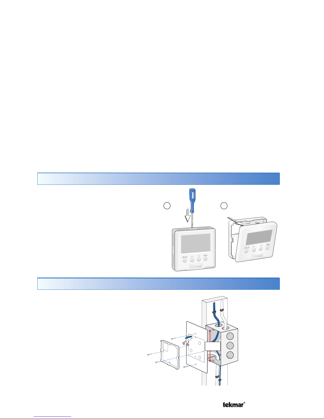
Removing The Thermostat Base
Push
tab
1
Remove thermostat
from base
2
To remove the thermostat base:
Place a small slot screwdriver or similar
tool into the slot located on the top of
the thermostat.
While pushing down against the plastic
tab, pull the thermostat away from the
thermostat’s base.
•
•
Mounting The Thermostat Base
Stud
Switch
Box
Thermostat
Base
007 Adaptor
Plate
3
1
/4”
(83 mm)
If a single gang switch box is used,
an Adaptor Plate 007 is required to
mount the thermostat to the box.
Fasten the base of the
thermostat to the adaptor plate.
Feed the wiring through the
openings in the back of the
adaptor plate and thermostat.
Use the upper and lower screw
holes to fasten the adaptor plate
to the box.
•
•
•
Mounted on switch box
Page 4
4 of 24© 2010 D 540 - 08/10
If a switch box was not used, mount the
thermostat directly to the wall.
Feed the wiring through the openings in
the back of the thermostat.
Use screws in the screw holes to fasten the
thermostat to the wall. At least one of the
screws should enter a wall stud or similar
rigid material.
•
•
Stud
2
3
/8”
(60 mm)
screwhole
2
3
/8”
(60 mm)
screwhole
Thermostat
Base
Wall
Mounted on wallboard
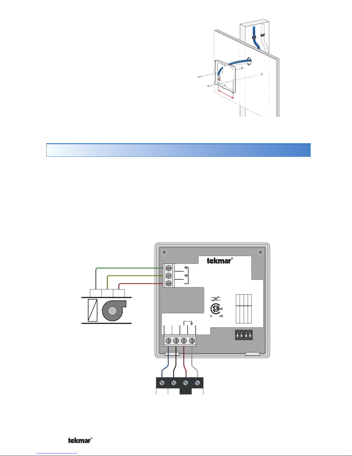
Thermostat Wiring
The thermostat operates a single heating system zone together with a cooling
system and fan.
Connect tN4, C, R, and W terminals on the thermostat to the tN4, C, R and W terminals
on the tN4 Wiring Center or Zone Manager.
Connect the Rc, Y and G terminals on the thermostat to the R, Y and G terminals
on the cooling equipment.
12 34
tN4 Wiring Center
or
tN4 Zone Mana
g
er
Cooling Equipment
1 Stage
Cooling
1 Stage
Fan
G Y R
D
X
Fan
Cooling
tN4 C W
R
1234
tNt 540
540
One Stage Heat /
One Stage Cool / One Fan
Made in
Canada
Mmm YYYY
Lot # 12345
Meets Class B:
Canadian ICES
FCC Part 15
Power: 24 V ±10% 50/60 Hz 1.8 VA
56 VA fully loaded
Relays: 24 V (ac) 2 A
1001-01
tN41C2R3W
4
7
G
6
Y
5
Rc
Switch Settings:
For instructions see brochure
Use at least 75°C conductors
Setback
Scene
None
Lock
ON
Unlock
Cool Master 1
Off
Off
Page 5

5 of 24 © 2010 D 540 - 08/10
Testing the Thermostat Wiring
Testing the Power
---------------------------------------------------
---------------------------------------------------
1. Remove the front cover from the thermostat.
2. Use an electrical test meter to measure (ac) voltage between the R and C
terminals. The reading should be 24 V (ac) +/– 10%.
3. Install the front cover.
Testing the Heat, Cool, and Fan Relays
--------------------------------
--------------------------------
1. Remove the front cover from the thermostat.
2. Press Mode button until Mode is set to OFF.
3. Set the electrical test meter to continuity.
4. Place probes between R (3) and W (4), then between Rc (5) and Y (6). In both
cases there should be no continuity. If there is continuity then there may be a
wiring fault or the relay may be faulty.
5. Press Mode button until Mode is set to HEAT.
6. Press the button and set the heating temperature above the current room
temperature. Make sure the display does not show “WWSD”. The “H1” symbol
should appear on the display.
7. There should be continuity between the R (3) and W (4) terminals.
8. Press Mode button until Mode is set to COOL.
9. Press the button and set the cooling temperature below the current room
temperature. The “C1” symbol should appear on the display.
10. There should be continuity between the Rc (5) and Y (6) terminals.
11. Press Fan button to set the fan to Auto.
12. Ensure the fan symbol is not shown on the display.
13. There should be no continuity between Rc (5) and G (7) terminals.
14. Press Fan button to set the fan to On.
15. The “Fan” symbol should appear on the display.
16. There should be continuity between the Rc (5) and G (7) terminals.
Page 6
6 of 24© 2010 D 540 - 08/10
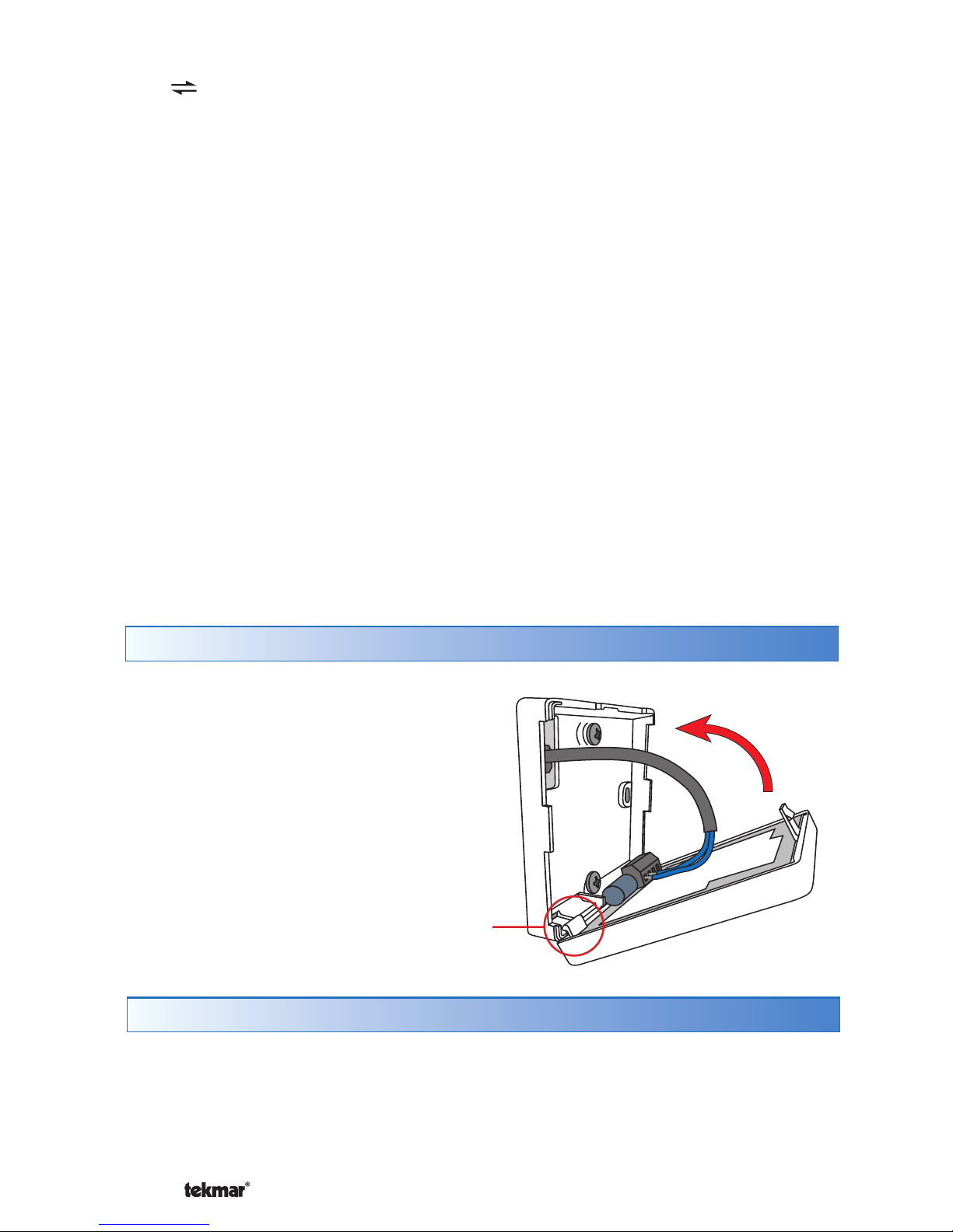
Mounting the Thermostat
To place the thermostat back on the
mounting base:
Place thermostat bottom tabs on
matching mounting base notches.
Pivot top of the thermostat
towards wall, ensuring wires clear
obstructions.
The top clasp makes a clicking
sound when properly closed.
•
•
•
Pivot
Tab
The thermostats’s exterior can be cleaned using a damp cloth. Moisten the cloth
with water and wring out prior to wiping the control. Do not use solvents or cleaning
solutions.
Cleaning the Thermostat
Testing the tekmarNet®4 Bus
-----------------------------------------
-----------------------------------------
The symbol is shown on the display when communication is present. If the
thermostat is connected in a network and the communication is missing, there may
be an open or short circuit on the tN4 and C bus wires.
1. Remove the front cover from the thermostat.
2. To test for short circuits:
Disconnect the tN4 bus wires on one end.
Install wire nuts on each wire to ensure the wire ends are not touching.
Disconnect the tN4 bus wires on the other end.
Measure for continuity using an electrical meter.
If continuity is present, there is a short circuit fault along the wires. It is
recommended to replace the tN4 bus wires.
3. To test for open circuits:
Disconnect the tN4 bus wires on one end and connect them together.
Disconnect the tN4 bus wires on the other end.
Use an electrical meter to measure for continuity.
If there is no continuity, there is an open circuit fault along the wires. It is
recommended to replace the tN4 bus wires.
•
•
•
•
•
•
•
•
•
Page 7
7 of 24 © 2010 D 540 - 08/10
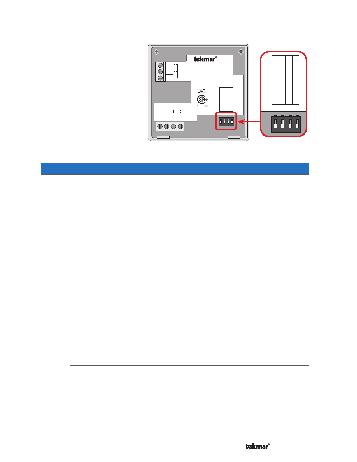
Switch Settings
Switches are set to “On”
position from the factory, and
do not require changing for
most applications.
12 34
1234
tNt 540
540
One Stage Heat /
One Stage Cool / One Fan
Made in
Canada
Mmm YYYY
Lot # 12345
Meets Class B:
Canadian ICES
FCC Part 15
Power: 24 V ±10% 50/60 Hz 1.8 VA
56 VA fully loaded
Relays: 24 V (ac) 2 A
1001-01
tN41C2R3W
4
7
G
6
Y
5
Rc
Switch Settings:
For instructions see brochure
Use at least 75°C conductors
Setback
Scene
None
Lock
ON
Unlock
Cool Master 1
Off
Off
12 34
1234
Mm
Meets Class B:
Switch Settings:
Setback
Scene
None
Unlock
ON
Lock
Cool Master 1
Off
Off
Switch
Position
Action
1
ON
SETBACK
The thermostat follows a programmable setback schedule
as a schedule member if available. Requires the installation
of a Timer 033 to use this feature.
OFF
OFF
The thermostat does not follow a programmable setback
schedule.
2
ON
SCENE
The thermostat responds to changes in the scene (system
wide manual overrides). Requires the installation of a User
Switch 479 to use this feature.
OFF
OFF
The thermostat does not respond to scenes.
3
ON
NONE
The thermostat is not part of a cooling group.
OFF
COOL MASTER 1
The thermostat is a master of cooling group number 1.
4
ON
LOCK ACCESS LEVEL
Locked to ‘User’ access level. Set to Lock when installation
completed.
OFF
UNLOCK ACCESS LEVEL
Unlock to allow ‘User’ and “Installer’ access level. Set to
Unlock during installation process.
tekmarNet® reset control must also be set to Unlocked
(Installer access level).
Page 8
8 of 24© 2010 D 540 - 08/10
SECONDARY DISPLAYMAIN DISPLAY
HEAT
Heat is turned on.
COOL
Cooling is turned on.
FAN
Fan is turned on.
SUN
Operating at the occupied
(day) temperature.
MOON
Operating at the unoccupied
(night) temperature.
COOL GROUP MASTER
Thermostat operates the
cooling for a group of
thermostats.
CLOCK
Operating on a
programmable schedule.
LOCK
Locked to ‘User’ access level.
AWAY
Operating at the Away scene
temperature.
tekmarNet
®
Communication is present.
WARNING SYMBOL
Indicates an error is present.
WARM WEATHER SHUT
DOWN
The heating system has been
shut off for the summer.
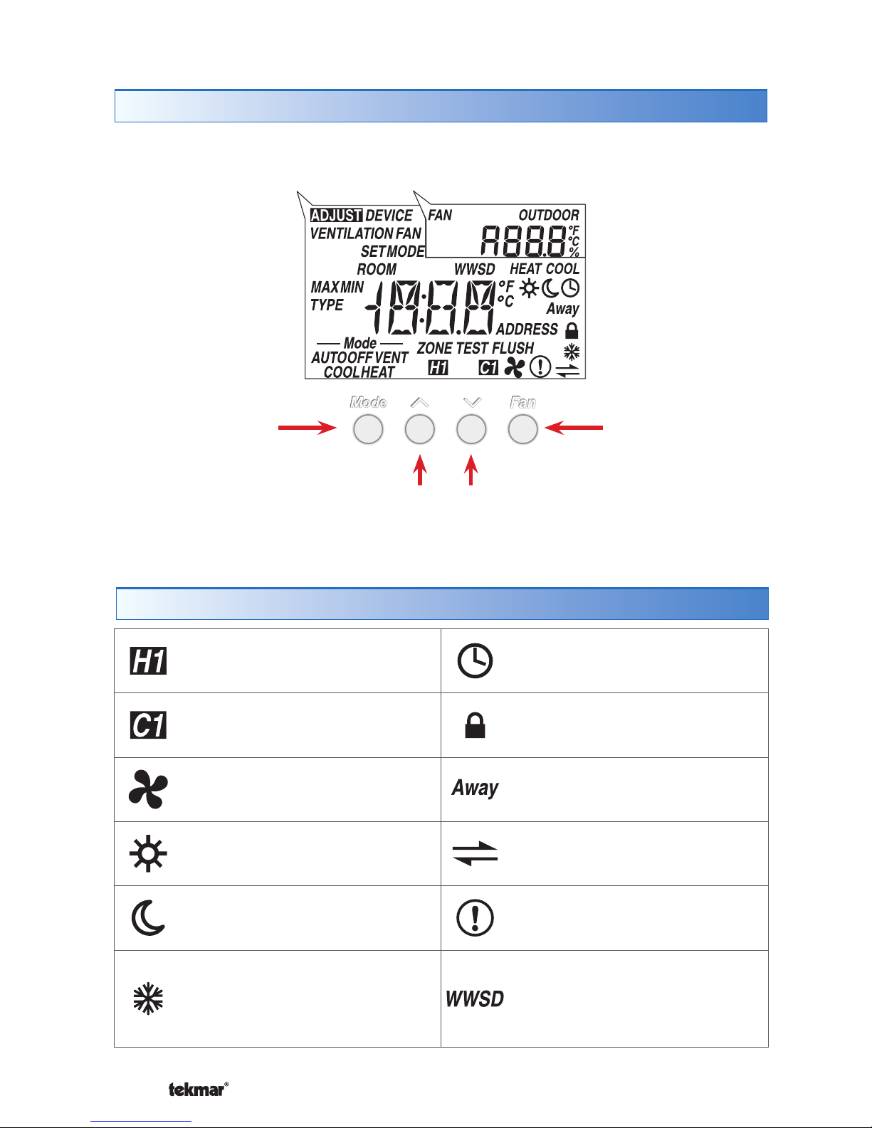
Display
Symbols Description
Switch between
Heat, Cool, Auto
and Off modes
Switch between
Auto, On and %
Fan operation
Adjust the current temperature
or displayed setting up or down
User Interface
Page 9

9 of 24 © 2010 D 540 - 08/10
Button Operation
The Mode button selects between Auto, Cool, Heat, and Off.
Heat Mode: The heating system operates to maintain the Set
Room Heat temperature.
Cool Mode: The cooling system operates to maintain the Set Room
Cool temperature.
Auto Mode: The heating system operates to maintain the Set Room Heat temperature.
Likewise the cooling system operates to maintain the Set Room Cool temperature.
The thermostat will prevent the Set Room Heat and the Set Room Cool settings
from getting closer than 3°F (1.5°C).
To switch from heating to cooling, the heat must be off for at least a 30 minute
interlock period and the actual Room temperature must be at least 3°F (1.5°C)
above the Set Room Heat temperature.
To switch from cooling to heating, the cooling must be off for at least a 30 minute
interlock period and the Room temperature must be at least 3°F (1.5°C) below
the Set Room Cool temperature. Cooling has priority over heating.
Off Mode: The heating and cooling are shut off except heating for freeze
protection.
Mode
---------------------------------------------------------------
---------------------------------------------------------------
Fan
-----------------------------------------------------------------
-----------------------------------------------------------------
The fan button manually turns the fan on or off.
Auto: Fan is usually off but can operate with heating or cooling.
On: Fan is on all the time.
10 to 90%: Fan operates a minimum of this percentage each hour.
Press the or the button to select the room temperature. The display indicates
whether the “HEAT” or the “COOL” temperature is being changed.
Use the or
button to adjust
temperature.
If in Auto mode, press the Mode
button to toggle between Heat or
Cool temperature adjustment.
Room or Temperature
------------------------------------------
------------------------------------------
Page 10

10 of 24© 2010 D 540 - 08/10
Settings (1 of 6)
Display Range Access Description Set to
40 to 95°F
(4.5 to 35.0°C)
Default = 70°F
(21.0°C)
Installer
User
SET ROOM HEAT
Set the room heating temperature while in the
event.
40 to 95°F
(4.5 to 35.0°C)
Default = 65°F
(18.5°C)
Installer
User
SET ROOM HEAT
Set the room heating temperature while in the
event.
40 to 95°F
(4.5 to 35.0°C)
Default = 62°F
(16.5°C)
Installer
SET ROOM HEAT AWAY
Set the room heating temperature while in the Away
scene.
Continued on next page.
• Press and hold down both the and buttons for 2 seconds to change from one step to the next.
• Release both buttons once the step has been reached.
• Press the or the button to change the setting, if available.
• Press and hold down both the
and buttons for 2 seconds to go to the next step, OR
• After 10 seconds of no button activity, the display goes back to normal operation.
• Note: Set switch setting #4 and tekmarNet
®
system control to Unlock to change Access level to Installer.
Press
+
Together
Page 11

11 of 24 © 2010 D 540 - 08/10
Settings (2 of 6)
Display Range Access Description Set to
50 to 100°F
(10.0 to 38.0°C)
Default = 78°F
(25.5°C)
Installer
User
SET ROOM COOL
Set the room cooling temperature while in the
event.
50 to 100°F
(10.0 to 38.0°C)
Default = 85°F
(29.5°C)
Installer
User
SET ROOM COOL
Set the room cooling temperature while in the
event.
50 to 100°F
(10 to 38.0°C)
Default = 85°F
(29.5°C)
Installer
SET ROOM COOL AWAY
Set the room cooling temperature while in the Away
scene.
Off, 30 sec, On,
On +
Default = 30 sec
Installer
User
BACKLIGHT
Select the backlight operation.
Off = Permanently Off
30 = Temporary on for 30 seconds
On = Permanently On
On + = On during and off during
Continued on next page.
Page 12

12 of 24© 2010 D 540 - 08/10
Display Range Access Description Set to
°F or °C
Default = °F
Installer
User
TEMPERATURE UNITS
Press the or the button to change from °F to
°C and vice versa.
Device Type with
Software Version,
Address
Installer
User
DEVICE TYPE
Display alternates between the Device Type (large
number) with Software Version (upper right corner)
and the thermostat address.
40 to 95°F
(4.5 to 35.0°C)
Default = 85°F
(29.5°C)
Installer
MAXIMUM SET ROOM HEAT
Set the maximum room heating limit while in the
event.
40 to 95°F
(4.5 to 35.0°C)
Default = 85°F
(29.5°C)
Installer
MAXIMUM SET ROOM HEAT
Set the maximum room heating limit while in the
event.
40 to 95°F
(4.5 to 35.0°C)
Default = 45°F
(7.0°C)
Installer
MINIMUM SET ROOM HEAT
Set the minimum room heating limit.
Settings (3 of 6)
Continued on next page.
Page 13

13 of 24 © 2010 D 540 - 08/10
Display Range Access Description Set to
50 to 100°F
(10 to 38.0°C)
Default = 60°F
(15.5°C)
Installer
MINIMUM SET ROOM COOL
Set the minimum room cooling limit.
50 to 100°F
(10.0 to 38.0°C)
Default = 95°F
(35.0°C)
Installer
MAXIMUM SET ROOM COOL
Set the maximum room cool limit.
OFF, On
Default = OFF
Installer
VENTILATION
Select whether or not ventilation is required.
Setting to on allows the fan to be operated in 10%
increments every hour to circulate air in the building.
0, 1, 2, 3
Default = 1
Installer
FAN MODE
Select how the fan should operate together with heating
and cooling.
0 = Manual operation only
1 = Operate fan with cooling only
2 = Operate fan with heating and cooling
3 = Operate fan with heating only
Settings (4 of 6)
Continued on next page.
Page 14

14 of 24© 2010 D 540 - 08/10
Display Range Access Description Set to
Auto, 10 to 90%,
On
Default = Auto
Installer
User
FAN
Set the minimum percentage the fan should operate
while in the event. This provides ventilation for the
building. Each 10% is 6 minutes per hour.
Available when:
• Ventilation is set to On.
Auto, 10 to 90%,
On
Default = Auto
Installer
User
FAN
Set the minimum percentage the fan should operate
while in the event. This provides ventilation for the
building. Each 10% is 6 minutes per hour.
Available when:
Ventilation is set to On.•
1, 2, 3, 4
Default = 1
Installer
SCHEDULE
Thermostat can follow schedule master 1, 2, 3, or 4.
Available when:
Switch setting 1 is set to Setback (On Position).•
Hyd (Hydronic)
or Oth (Other)
Default =
Hydronic
Installer
HEATING TERMINAL TYPE
Select if the heating for this zone is hydronic or non-
hydronic (other).
Available when:
A reset control is present on the tekmarNet
®
system.
•
Settings (5 of 6)
Continued on next page.
Page 15

15 of 24 © 2010 D 540 - 08/10
Display Range Access Description Set to
Auto,
SYn(Synchronize)
Default =
Synchronize
Installer
HEAT CYCLES PER HOUR
Select either Auto cycle or Synchronize with other
thermostats on the tekmarNet
®
system.
Choose Synchronize when zone heated using a boiler.
Choose Auto when zone is non-hydronic heating.
Available when:
No reset control on the tekmarNet
®
system.•
OFF, dLy (delay),
On
Default = On
Installer
HEATING SUPPLY PUMP
Select whether or not the system supply pump should
turn on, be delayed (for thermal motor or wax actuator)
or be off to allow a zone group pump per manifold.
Available when:
A reset control is present on the tekmarNet
®
system
AND Heating terminal type is set to Hydronic.
•
01 to 24
(no reset control),
b:01 to b:24
(reset control - boiler),
1:01 to 1:24
(reset control - mixing)
Installer
tekmarNet
®
ADDRESS
The address is shown in the large number field. “Auto” is
shown in the upper number field when using automatic
addressing.
Press the or the button to manually select
an address.
The address can be returned to automatic “Auto”
addressing when address set above 24.
None
Installer
User
ESCAPE
Press the or the button to return to normal
operation.
Settings (6 of 6)
Page 16

16 of 24© 2010 D 540 - 08/10
Heating Operation
Section A
Sequence of Operation
The thermostat operates the heating system to maintain the Set Room Heat
temperature. The H1 symbol is shown on the display when the thermostat is
heating. The heat can cycle on and off within +/- 1.5°F (1°C) of the Set Room
Heat temperature.
Freeze Protection
----------------------------------------------------
----------------------------------------------------
The thermostat operates the heat whenever the room temperature falls below 40°F
(4.5°C), regardless of the thermostat mode.
Heat Terminal Unit
---------------------------------------------------
---------------------------------------------------
When the thermostat is connected to a tekmarNet® reset control, the heat source
can be either hydronic or non-hydronic.
When the Heat Terminal is set to Hydronic, the thermostat uses indoor temperature
feedback to fine tune the water temperature and also synchronizes the start of a
heating cycle so that all thermostats start heating at the same time. This reduces
cycling on the boiler.
When the Heat Terminal is set to Other, the thermostat does not use indoor
temperature feedback. This allows the thermostat to operate non-hydronic heating
systems (example: furnace, electric baseboard, or electric fan coil), while remaining
connected to the tekmarNet® system.
Exercising
----------------------------------------------------------
----------------------------------------------------------
When connected to a tekmarNet® reset control, and the heating terminal unit is set
to hydronic, the thermostat exercises the heat relay for 10 seconds every 3 days.
Exercising helps prevent zone valves or zone pumps from failing due to precipitate
buildup. During exercising, the thermostat shows “TEST” on the display.
Flushing
------------------------------------------------------------
------------------------------------------------------------
The flushing feature is for open-loop systems that use a domestic hot water tank
as a heat source. Flushing ensures that fresh potable water is circulated through
the system once each day. If the thermostat is connected to a tekmarNet® reset
control with the Flushing feature turned on, the thermostat display will display the
“FLUSH” icon for the duration of the flushing operation.
Hydronic System Supply Pump
---------------------------------------
---------------------------------------
When connected to a tekmarNet® reset control, the thermostat’s Supply Pump
setting affects how the primary pump or mix pump on the reset control operates.
When connected to the boiler bus, the primary pump is affected. When connected
to the mix bus, the mix system pump is affected.
If the thermostat operates a motorized zone valve or a zone pump, the Supply
Pump setting should be set to On.
Page 17

17 of 24 © 2010 D 540 - 08/10
Cooling Operation
Section B
The thermostat operates the cooling system to maintain the Set Room Cool
temperature. The C1 symbol is shown on the display when the thermostat is
cooling. The cooling can cycle on and off within +/- 1.5°F (1°C) of the Set Room
Cool temperature.
The cooling system has a fixed minimum on time of 2 minutes and a minimum off
time of 5 minutes in order to prevent cooling equipment short cycling.
Cooling Groups
-----------------------------------------------------
-----------------------------------------------------
In order to prevent heating and cooling at the same time, this thermostat can operate
together with other thermostats on a tekmarNet® system to form a cool group. When
this thermostat is set as the Cool Group 1 master, it operates the cooling equipment
for the group. Other thermostats can be set to become members of cool group
1. When the cooling is turned on, all cool group member thermostats ensure the
heating is off. This thermostat is the master of Cool Group 1 when switch setting
3 is set to “Cool Master 1” (down position). When operating as a cool group, the
air temperature readings of all the cool group member thermostats are displayed
on the master as an average.
The cool group average temperature is shown as the “Room” temperature while
the mode is set to Cool, or the mode is set to Auto and the thermostat is allowing
cooling operation. In all other modes, the
cool group master thermostat measures
and displays the built-in “local” temperature
sensor measurement.
Fluctuations in the displayed “Room”
temperature may occur during automatic
mode switch over when the display changes
from using the local temperature for heating
to using the cool group average temperature
for cooling.
Cool Group 1
Master
MemberMember
tN2 Communication
If the thermostat operates a thermal motor (wax actuator) zone valve, set the Supply
Pump setting to Delay. This provides a three minute delay to allow the zone valve to
open before the primary or mix pump is turned on and the boiler is allowed to fire.
In special applications with multiple zoning manifolds, the Supply Pump setting
can be set to Off. This allows a Zone Group Pump located on the Zone Manager,
or Wiring Center to operate the pump for the manifold.
DHW Tank Priority
---------------------------------------------------
---------------------------------------------------
When a tekmarNet® reset control is heating an indirect Domestic Hot Water (DHW)
tank, the thermostat may shut off the heating zones to allow the DHW tank to recover
quickly. This is determined by the DHW priority of the tekmarNet® reset control.
Warm Weather Shut Down
--------------------------------------------
--------------------------------------------
When the outdoor air temperature exceeds the Warm Weather Shut Down (WWSD)
setting on the tekmarNet® reset control, the heating system is shut off.
Page 18

18 of 24© 2010 D 540 - 08/10
The fan relay includes a post purge feature. After the heating is shut off, the fan
continues to operate for 30 seconds. After the cooling is shut off, the fan continues
to operate for 10 seconds.
The user can also select to operate the fan manually by pressing the Fan button.
This allows the user to choose between Auto and On. “Auto” allows the fan to
operate together with heating or cooling but normally the fan is off. “On” forces the
fan to operate continuously.
The fan button is inactive when the Fan Mode is 0 and Ventilation is set to Off.
Ventilation Fan
------------------------------------------------------
------------------------------------------------------
In order to provide ventilation to the building, the fan can also operate for additional
time beyond what is required for the heating and cooling systems. Ventilation allows
the user to select the fan to operate for a minimum percentage out of each hour.
Options are 10 to 90%, in 10% (6 minutes per hour) increments, as well as Auto and
On. This is available when the Ventilation setting in the Adjust menu is set to On.
Once Ventilation is set to On, the Fan minimum run time percentage during the
and events can be set so that the fan can operate on a schedule and/or together
with scenes.
Fan Operation
Section C
Fan Mode The fan operates with...
0 Not With Heating Nor Cooling (Only with fan button)
1 Cooling Only
2 Heating and Cooling
3 Heating Only
The thermostat normally operates the fan together with the heating and cooling
systems. This is determined by the Fan Mode setting in the Adjust menu.
Page 19

19 of 24 © 2010 D 540 - 08/10
Schedules
Section D
Lowering the room temperature setting reduces the amount of fuel required to heat
the building resulting in energy savings. Likewise, raising the cooling temperature
results in energy savings.
This thermostat can follow a programmable schedule in order to automatically lower
the room temperature setting. A schedule master such as a Timer 033 is required
in order to gain programmable schedule functionality.
When operating on a programmable schedule, a
symbol is shown, as well as a
or a . The or indicates the current operating temperature.
If a symbol does not appear, there is no schedule available.
Display Action
Occupied temperature. No schedule.
Unoccupied temperature. No schedule.
Programmable schedule at
occupied
temperature.
Programmable schedule at
unoccupied
temperature.
Scene Display Room Temperature Setting
1
or or
Follows programmable schedule or
operates at the occupied temperature.
2
Away
Away temperature.
3
Unoccupied temperature.
Scenes (System Override)
Section E
When a programmable schedule is selected, there is a time delay for the temperature
to change from the temperature to the temperature.
The thermostat uses Optimum Start to predict the heat up and cool off rate of
the room. The optimum start feature allows the room to reach the set room
temperature by the time set in the programmable schedule. This applies for both
heating and cooling.
Scenes provide an easy way to save energy while away on vacation, or override a
pre-set schedule when plans change. tekmarNet® devices such as a User Switch
479 provide scene adjustment.
This thermostat responds to the following scenes:
While in the Away scene, the room temperature cannot be changed using the or
buttons. Change the scene from Away to or to change the temperature.
Page 20

20 of 24© 2010 D 540 - 08/10
Troubleshooting
Error Messages (1 of 2)
Error Message Description
CONTROL ERROR
The thermostat was unable to correctly read settings from memory and has reloaded the factory
default settings. The thermostat does not operate the heating, cooling, or the fan while this error
message is present.
Error clears once all adjust menu settings in the Installer access level (unlocked) have been
checked. Set thermostat’s switch setting #4 to unlock and unlock the tekmarNet
®
system control.
Then press and hold and buttons together for 2 seconds to enter the adjust menu. Continue
until all settings have been reveiwed.
BUS ERROR
The tekmarNet
®
4 communication bus has either an open or a short circuit. The result is that there
are no communications. Check for loose wires. Check for short circuits between the tN4 and C
wires on the House Control, Wiring Center, or Zone Manager. Check for correct polarity between
the C and R wires.
Error clears automatically once wiring fault has been corrected.
If the thermostat is intentionally removed from the tekmarNet
®
4 bus, press the and buttons
together to clear the error message.
DEVICE LIMIT
The number of devices on the tekmarNet
®
bus has exceeded 24. Devices include tekmarNet
®
Thermostats and Setpoint Controls. The device count must be lowered to 24 or less. If possible,
move devices to other tekmarNet
®
buses.
Error clears automatically once the number of devices on the tekmarNet
®
bus is at 24 or lower.
Page 21

21 of 24 © 2010 D 540 - 08/10
Error Messages (2 of 2)
Error Message Description
ADDRESS ERROR
This thermostat and another device have been manually given the same tekmarNet
®
address.
Error clears automatically once this thermostat is given a new manually set address or if the
thermostat is set to automatic addressing.
ROOM SENSOR SHORT CIRCUIT
The built-in air temperature sensor has a short circuit fault.
This error cannot be field repaired.
Contact your wholesaler or tekmar sales representative for details on repair procedures.
ROOM SENSOR OPEN CIRCUIT
The built-in air temperature sensor has an open circuit fault.
This error cannot be field repaired.
Contact your wholesaler or tekmar sales representative for details on repair procedures.
COOL MASTER ERROR
Switch #3 has been selected to become a cool group master of group number 1, and another cool
group master has been detected with the same group number.
The cooling system will not operate while this error message is present.
Error clears once either the other cool group master changes its group number or switch setting
#3 is set to none (On position).
Page 22

22 of 24© 2010 D 540 - 08/10
Symptom Look for... Corrective Action
No Heat
H1 Symbol
H1 symbol indicates heat is on. Check if zone
valve or zone pump is operating.
Flashing
WWSD
Increase WWSD setting on tekmarNet®
reset control.
Flashing
Away
Change User Switch to Normal scene 1.
Mode Auto or
Heat
Press Mode button to Auto or Heat mode.
No Cooling
C1 Symbol
C1 symbol indicates cooling is on. Check
if cooling relay and cooling equipment are
operating.
Flashing
Away
Change User Switch to Normal scene 1.
Mode Auto or
Cool
Press Mode button to Auto or Cool mode.
Heat or Cooling
on yet Fan off
Fan symbol
Fan symbol indicates fan is on. Check if fan
relay and fan equipment is operating.
Fan set to Off Ensure fan mode is set correctly.
Heat or cooling
on before
scheduled time
Optimum start “learns” the heat up and
cool off rate of the room and starts the
heating or cooling early so that the room is
comforable at the scheduled time.
Pressing button
does not increase
temperature
Flashing Max
Installer can increase the Maximum Set Room
Heat or Maximum Set Room Cool limits.
Pressing button
does not decrease
temperature
Flashing Min
Installer can decrease the Minimum Set Room
Heat or Minimum Set Room Cool limits.
Frequently Asked Questions
Page 23

23 of 24 © 2010 D 540 - 08/10
Job Record
Item Setting
Set Room Heat
Set Room Heat
Set Room Heat Away
Set Room Cool
Set Room Cool
Set Room Cool Away
Backlight
Units
Max Set Room Heat
Max Set Room Heat
Min Set Room Heat
Item Setting
Min Set Room Cool
Max Set Room Cool
Ventilation
Fan Mode
Fan
Fan
Schedule Member
Heating Terminal Type
Heat Cycles Per Hour
Heating Supply Pump
tekmarNet® Address
Jobsite Location ________________________________________________
Thermostat Location _____________________________________________
Technical Data
tekmarNet®4 Thermostat 540; One Stage Heat, One Stage Cool, One Fan
Packaged weight 0.8 lb. (380 g)
Enclosure NEMA 1, white PVC plastic
Dimensions 2-7/8” H x 2-7/8” W x 13/16” D (73 x 73 x 21 mm)
Approvals CSA C US, meets Class B: ICES and FCC Part 15
Ambient conditions Indoor use only, 36 to 122°F (2 to 50°C).
RH max 92% to 104°F (40°C), and 50% above 104°F
(40°C)
Altitude <9840 feet (3000 m), Installation Category II,
Pollution Degree 2
Power supply
24 V (ac) ± 10% 50/60 Hz, 1.8 VA Standby, 56 VA fully
loaded, NEC / CEC Class 2
W, Y and G Relays 24 V (ac) 2 A
Page 24

tekmar Control Systems Ltd., Canada
tekmar Control Systems, Inc., U.S.A.
Head Office: 5100 Silver Star Road
Vernon, B.C. Canada V1B 3K4
(250) 545-7749 Fax. (250) 545-0650
Web Site: www.tekmarcontrols.com
Product design, software and literature
are Copyright © 2010 by:
tekmar Control Systems Ltd. and tekmar
Control Systems, Inc.
All specifications are subject
to change without notice
24 of 24 D 540 - 08/10.
Limited Warranty The liability of tekmar under this warranty is limited. The Purchaser, by taking receipt
of any tekmar product (“Product”), acknowledges the terms of the Limited Warranty in effect at the time
of such Product sale and acknowledges that it has read and understands same.
The tekmar Limited Warranty to the Purchaser on the Products sold hereunder is a manufacturer’s passthrough warranty which the Purchaser is authorized to pass through to its customers. Under the Limited
Warranty, each tekmar Product is warranted against defects in workmanship and materials if the Product
is installed and used in compliance with tekmar’s instructions, ordinary wear and tear excepted. The passthrough warranty period is for a period of twenty-four (24) months from the production date if the Product is
not installed during that period, or twelve (12) months from the documented date of installation if installed
within twenty-four (24) months from the production date.
The liability of tekmar under the Limited Warranty shall be limited to, at tekmar’s sole discretion: the cost of parts
and labor provided by tekmar to repair defects in materials and / or workmanship of the defective product; or to
the exchange of the defective product for a warranty replacement product; or to the granting of credit limited to
the original cost of the defective product, and such repair, exchange or credit shall be the sole remedy available
from tekmar, and, without limiting the foregoing in any way, tekmar is not responsible, in contract, tort or strict
product liability, for any other losses, costs, expenses, inconveniences, or damages, whether direct, indirect,
special, secondary, incidental or consequential, arising from ownership or use of the product, or from defects in
workmanship or materials, including any liability for fundamental breach of contract.
The pass-through Limited Warranty applies only to those defective Products returned to tekmar during the warranty period. This Limited Warranty does not cover the cost of the parts or labor to remove or transport the defective Product, or to reinstall the repaired or replacement Product, all such costs and expenses being subject to
Purchaser’s agreement and warranty with its customers.
Any representations or warranties about the Products made by Purchaser to its customers which are different
from or in excess of the tekmar Limited Warranty are the Purchaser’s sole responsibility and obligation. Purchaser
shall indemnify and hold tekmar harmless from and against any and all claims, liabilities and damages of any
kind or nature which arise out of or are related to any such representations or warranties by Purchaser to its
customers.
The pass-through Limited Warranty does not apply if the returned Product has been damaged by negligence by
persons other than tekmar, accident, fire, Act of God, abuse or misuse; or has been damaged by modifications,
alterations or attachments made subsequent to purchase which have not been authorized by tekmar; or if the
Product was not installed in compliance with tekmar’s instructions and / or the local codes and ordinances;
or if due to defective installation of the Product; or if the Product was not used in compliance with tekmar’s
instructions.
THIS WARRANTY IS IN LIEU OF ALL OTHER WARRANTIES, EXPRESS OR IMPLIED, WHICH THE GOVERNING
LAW ALLOWS PARTIES TO CONTRACTUALLY EXCLUDE, INCLUDING, WITHOUT LIMITATION, IMPLIED WARRANTIES OF MERCHANTABILITY AND FITNESS FOR A PARTICULAR PURPOSE, DURABILITY OR DESCRIPTION OF THE PRODUCT, ITS NON-INFRINGEMENT OF ANY RELEVANT PATENTS OR TRADEMARKS, AND
ITS COMPLIANCE WITH OR NON-VIOLATION OF ANY APPLICABLE ENVIRONMENTAL, HEALTH OR SAFETY
LEGISLATION; THE TERM OF ANY OTHER WARRANTY NOT HEREBY CONTRACTUALLY EXCLUDED IS LIMITED SUCH THAT IT SHALL NOT EXTEND BEYOND TWENTY-FOUR (24) MONTHS FROM THE PRODUCTION
DATE, TO THE EXTENT THAT SUCH LIMITATION IS ALLOWED BY THE GOVERNING LAW.
Product Warranty Return Procedure All Products that are believed to have defects in workmanship or materials must be returned, together with a written description of the defect, to the tekmar Representative assigned to
the territory in which such Product is located. If tekmar receives an inquiry from someone other than a tekmar
Representative, including an inquiry from Purchaser (if not a tekmar Representative) or Purchaser’s customers,
regarding a potential warranty claim, tekmar’s sole obligation shall be to provide the address and other contact
information regarding the appropriate Representative.
Limited Warranty and Product Return Procedure
 Loading...