

Page 1
1 of 20 © 2009 D 512 - 09/09
- Data Brochure
Programmable Thermostat 512
D 512
09/09
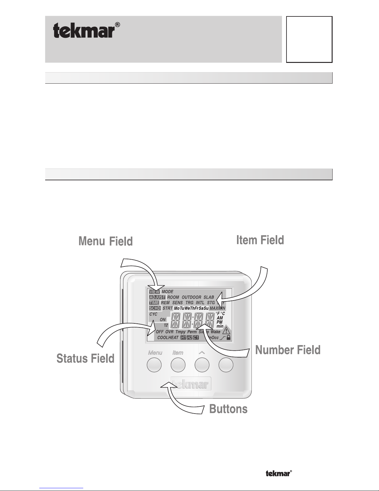
Displays the
current
menu
Displays an abbreviated
name of the selected item
Displays the current value
of the selected item
Selects Menus, Items
and adjusts settings
Displays the current
status of the
thermostat's inputs,
outputs and operation
Table of Contents
Display / Keypad Operation ............ pg 1
Display Symbols ............................. pg 2
General ........................................ pg 2-3
Sequence of Operation................ pg 4-6
Type 512 (Two Stage Heating) ... pg 4
Type 512 (Heat / Cool) ............pg 5-6
Menus ........................................ pg 6-10
View Menu ................................ pg 6
Adjust Menu ........................pg 7-10
Error Messages ......................pg 11
Installation .................................pg 12-13
Wiring the 512 ...........................pg 14-17
Warranty ....................................... pg 20
The thermostat’s display has four distinct fields. These fields are the Menu field, the Item
field, the Number field and the Status field. The four buttons on the face of the thermostat are
used to navigate through the menus and items to view and / or adjust the desired settings.
Display / Keypad Operation
Page 2
© 2009 D 512 - 09/09 2 of 20
Display Symbols
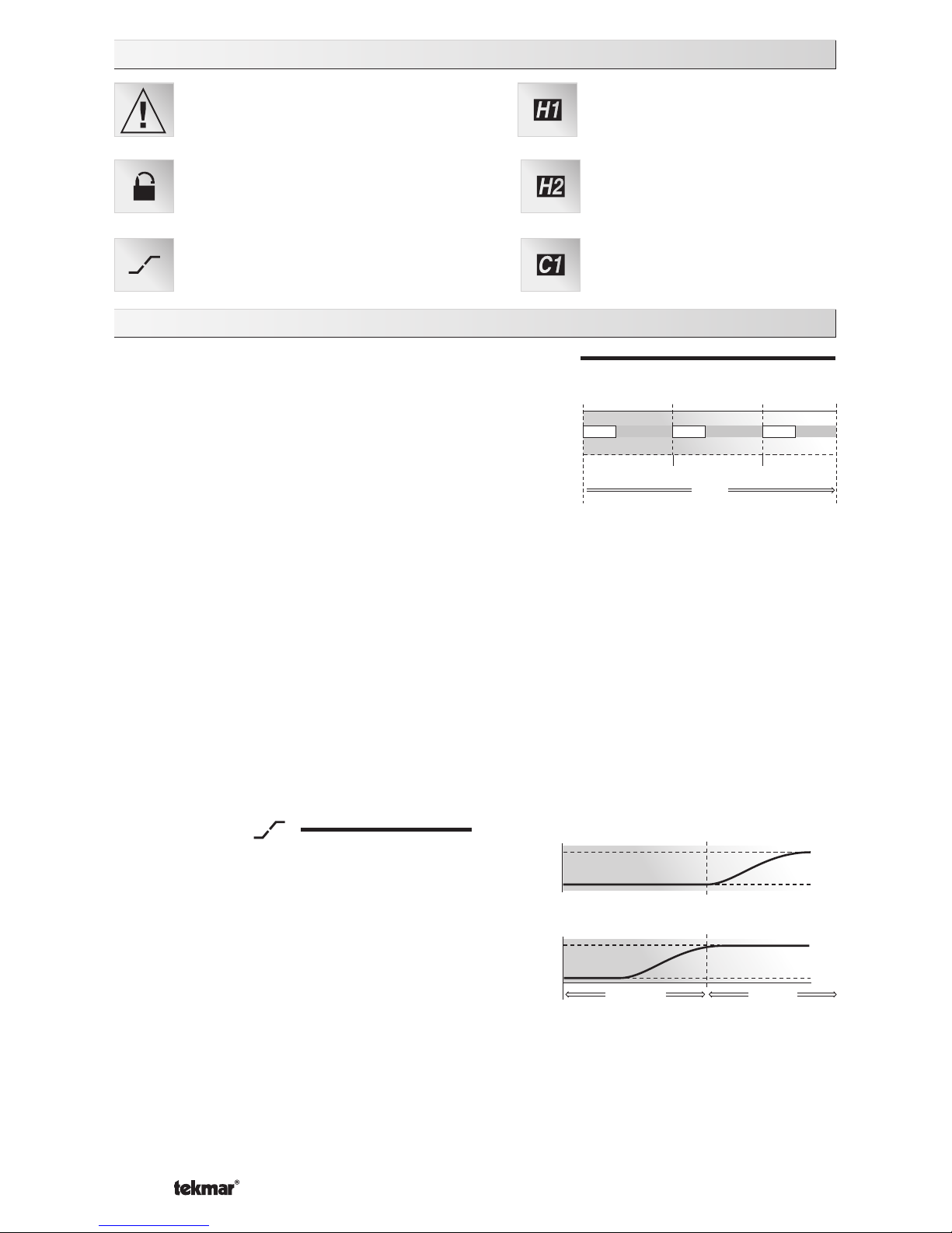
Warning
Displays when an error exists.
Access Level
Displays when in the user
access level.
Heat One
Displays when the heat one
contact is on.
Early Start
Displays when the thermostat
is in early start.
General
CYCLES PER HOUR (HEAT CYCLE and COOL CYCLE)
Heat Two
Displays when the heat two
contact is on.
Cool One
Displays when the cool one
contact is on.
⇐ Cycle Length ⇒
Time
offoff
off
on onon
Cycles Per Hour
The thermostat operation is based on cycles per hour.
The number of cycles per hour is adjustable through
the HEAT CYCLE and COOL CYCLE settings in the
Adjust menu. During each cycle that heating or cooling
is required, the thermostat turns on the Heat or Cool
relay(s) for a calculated amount of time. This amount of
time is the “on time”. The on time is calculated based on
the requirements of the zone. If the zone requires more heating or cooling, the appropriate
on time is increased. If the zone requires less heat or cooling, the appropriate on time is
reduced.
In order to prevent short cycling of the heating relay(s), the thermostat ensures that the
relay(s) remains on or off for a minimum amount of time. In order to prevent short cycling
of the Cool relay, the minimum cooling on time and minimum cooling off time settings are
adjusted in the Adjust menu of the 512.
An Auto Cycle setting is available for both the heating cycle and the cooling cycle. This
setting allows the thermostat to determine the best number of cycles per hour that balances
both temperature swings and equipment cycles.
EARLY START (
)
Heating - The early start function for heating
ensures that the zone is up to the proper
temperature at the beginning of each period.
The thermostat learns the recovery rate over
multiple setback events in order to determine
the proper lead time for the zone. If both an
air sensor and a slab sensor are used, the
lead time is the greater of the air sensor’s or
the slab sensor’s requirements.
Occupied
70°F (21°C)
62°F (17°C)
70°F (21°C)
62°F (17°C)
UnOccupied
Early Start OFF
Early Start ON
Cooling - The early start function, when used with cooling, allows the cooling system to
turn on 30 minutes prior to the beginning of a period that requires cooling.
NOTE: The Early Start feature occurs when the schedule changes from a low temperature
to a higher temperature.
Page 3

3 of 20 © 2009 D 512 - 09/09
AUXILIARY SENSORS
The thermostat has a single built-in sensor to measure air temperature at the thermostat. In
addition to the built-in sensor, the thermostat has terminals to connect up to two separate
sensors. These sensors can be either indoor sensors, slab sensors, a remote sensor, or
an outdoor sensor.
Indoor Sensor
An indoor sensor is used to measure the air temperature in the zone that the thermostat
is controlling. The temperature being read by the indoor sensor is used in the calculations
of the on times for the relay(s) in the thermostat. Either one or both of the auxiliary sensor
inputs can be configured for indoor sensors. This setting is made through the Adjust menu
of the thermostat. If more than one sensor, either the built-in sensor or an auxiliary sensor
set as an indoor sensor, is being used to measure the zone temperature, the temperature
of the active sensors is averaged and used to calculate the on time of the relay(s).
Slab Sensor
A slab sensor is used to measure the slab temperature in the zone that the thermostat
is controlling. The temperature being read by the slab sensor is used in the calculations
of the on time for the Heat relay and allows the thermostat to operate the slab between
the slab minimum and slab maximum settings. If more than one slab sensor is used, the
slab temperatures are averaged by the thermostat.
Remote Sensor
A single remote sensor can be connected to the thermostat. The temperature
measured by a remote sensor does not affect the on time of the relays and is only
used for display purposes.
Outdoor Sensor
A single outdoor sensor can be connected to the thermostat. The temperature measured
by an outdoor sensor does not affect the on time of the relays and is only used for display
purposes.
ACCESS LEVELS
The tekmar Programmable Thermostat has two
access levels. These access levels restrict the
number of items available in the menus of the
thermostat. The two access levels are User and
Installer. This selection is made using the DIP
switch located on the circuit board inside the
thermostat.
The Installer access level allows the installer to
adjust all of the settings in the thermostat including
those required to match the thermostat to the
mechanical system and the devices used.
The User access level allows the end user to
adjust the time, temperatures and schedules used
by the thermostat.
Power: 24 V ± 10%
60 Hz 3 VA
Relay:
24
V (ac) 2
A
Class 2
938-
02
512
Switch Settings:
Installer/User
2 Stag
e/Heat-Cool
Made in Canada
Meets Class B:
Canadian ICES
FCC Part 15
Dip Switch
Page 4

© 2009 D 512 - 09/09 4 of 20
TWO STAGE HEAT
The two stage mode of operation is selected using the DIP switch located on the circuit
board inside the thermostat.
In cases where a one stage heating system can not provide sufficient heat under all
conditions, a second stage of heat can be added to supplement the first stage. A two stage
system therefore has one thermostat controlling two output relays.
Two Stage Logic
The temperature in a two stage zone is controlled by varying the on time of the Heat 1
and Heat 2 relays during a cycle. Under light loads, the Heat 1 relay is cycled on and
off. As the load increases, the Heat 1 relay on time is increased until it reaches the
maximum of the cycle length or, if a slab sensor is used, the slab temperature reaches
the slab maximum setting. The Heat 2 relay is then cycled and its on time is increased
as the load increases. When the heating load decreases, the on time of the Heat 2
relay is reduced until the Heat 2 relay is turned off completely. The thermostat then
reduces the on time of the Heat 1 relay
.
NOTE: When using a slab sensor, the Heat 2 relay may be on while the Heat 1 relay is
off if the slab temperature has reached the slab maximum setting.
Air Sensor(s) Only Operation
When operating with only an air sensor, the on times for the Heat 1 and Heat 2 relays
are calculated to satisfy the requirements of the air sensor.
Slab Sensor Only Operation
When operating with only a slab sensor, the on times for the Heat 1 and Heat 2 relays
are calculated to satisfy the requirements of the slab sensor. The thermostat operates to
maintain the slab at the minimum slab temperature setting
.
NOTE: Operating with only a slab sensor can lead to either overheating or underheating
of the space.
Air and Slab Sensor Operation
When operating with both air and slab sensors, the thermostat calculates an on time for
the Heat 1 relay to satisfy the slab sensor’s requirements and on times for the Heat 1
and Heat 2 relays to satisfy the air sensor’s requirements. The thermostat operates the
Heat 1 relay for the longer of these two on times.
While the minimum slab temperature is satisfied, the on times of the Heat 1 and Heat 2
relays are calculated to satisfy the air temperature requirements
.
During heavy loads, the maximum slab temperature setting limits the on time of the Heat
1 relay. In this situation, the Heat 2 relay may be on while the Heat 1 relay is off.
NOTE: During light heating loads, overheating can occur due to the minimum slab
temperature requirements
.
Mode
Heat In the heat mode, the Heat 1 and Heat 2 relays are operated to satisfy the
temperature requirement of the zone
.
Off In the Off mode, the Heat 1 and Heat 2 relays are not operated.
NOTE: If an air or slab sensor is active in the Off mode, a freeze protection is enabled
that allows the relays to be operated to keep the zone above 35°F (2°C).
Page 5

5 of 20 © 2009 D 512 - 09/09
HEAT / COOL
The Heat / Cool mode of operation is selected using the DIP switch located on the circuit
board inside the thermostat
.
Air Sensor(s) Only Operation
When operating with only an air sensor, the on times of the Heat 1 relay and the Cool
relay are calculated to satisfy the requirements of the air sensor
.
Slab Sensor Only Operation
When operating with only a slab sensor, the on time of the Heat 1 relay is calculated to
satisfy the requirements of the slab sensor. The thermostat operates to maintain the slab
at the minimum slab temperature setting
.
NOTE: When operating with only a slab sensor, the Cool relay does not operate.
Operating with only a slab sensor can lead to either overheating or underheating of the
space.
Air and Slab Sensor Operation
When operating with both air and slab sensors, the thermostat calculates an on time
for the Heat 1 relay to satisfy the slab sensor’s requirements and an on time to satisfy
the air sensor’s requirements. The Heat 1 relay operates for the longer of these two
on times. The thermostat also calculates an on time for the Cool relay to satisfy the air
sensor’s requirements. In this situation, heating and cooling can happen at the same
time to prevent the space from overheating. This is most likely to occur when the slab is
operating at the slab minimum temperature
.
While the minimum slab temperature is satisfied, the Heat 1 relay on time is calculated
to satisfy the air temperature setting. However, the maximum slab temperature setting
limits the Heat 1 relay on time when the slab temperature becomes too warm. In this
situation, underheating can occur in the space.
Mode
Auto In the Auto mode, the thermostat automatically switches between heating and
cooling the space. However, the heating operation has priority over the cooling
operation. In this mode, the minimum slab temperature is maintained even when
the thermostat is cooling the air.
Heat In the Heat mode, the Heat 1 relay is operated to satisfy the heating
temperature requirement of the zone and cooling is disabled.
Cool In the Cool mode, the Cool relay is operated to satisfy the cooling temperature
requirement of the zone and heating is disabled. If a slab sensor is used, the slab
minimum is ignored.
Off In the Off mode, the Heat 1 and Cool relays are not operated.
NOTE: If an air or slab sensor is active in the Off mode, a freeze protection is enabled that
allows the Heat 1 relay to be operated to keep the zone above 35°F (2°C).
Page 6
© 2009 D 512 - 09/09 6 of 20
Heating / Cooling Interlock
Time Interlock
In order to prevent frequent changes between heating and cooling, the thermostat
has a Cooling Interlock setting. Once the Heat 1 relay has been off for a minimum of
one heating cycle or the length of the Cooling Interlock, (whichever is longer) cooling
is permitted.
Temperature Interlock
When in the Auto mode, the cooling temperature is limited to 3°F (1.5°C) above the
heating temperature. If the cooling temperature is set below the heating temperature,
the thermostat automatically adjusts the cooling setpoint.
When operating in the Cool mode, there is no interlock between the heating and cooling
temperature.
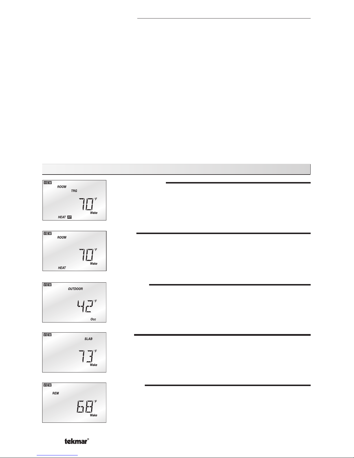
View Menu (1 of 1)
ROOM TARGET
The current desired air temperature for the space. This item is
only available in the Installer access level.
(Must have an active air sensor.)
ROOM
The current air temperature for the space.
(Must have at least one active air sensor. This is the average of
all active air sensors.)
OUTDOOR
The current temperature at the outdoor sensor .
(Sens 2 must be set to Out.)
SLAB
The current slab temperature.
(Must have an active slab sensor. If two slab sensors are present,
this is the average temperature.)
The MIN segment is displayed when running on Min.
REMOTE
The current temperature at the remote sensor.
(Sens 1 must be set to Rem.)
Page 7

7 of 20 © 2009 D 512 - 09/09
Adjust Menu (1 of 4)
MODE
Current mode of operation of the thermostat.
OFF, HEAT
OFF, COOL, AUTO, HEAT
ROOM HEAT (No Schedule)
Desired temperature for heating.
(Must have an active air sensor and be set to either Heat or Auto.)
35 to 100°F (1.5 to 38.0°C)
ROOM COOL (No Schedule)
Desired temperature for cooling.
(Must have an active air sensor and be set to either Cool or Auto.)
35 to 100°F (1.5 to 38.0°C)
SLAB MINIMUM (No Schedule)
Minimum slab temperature.
(Must have an active slab sensor.)
OFF, 34 to 122°F (OFF, 1.0 to 50.0°C)
ROOM HEAT WAKE
Desired temperature for heating during Wake.
(Must have an active air sensor and be set to either Heat or Auto.)
35 to 100°F (1.5 to 38.0°C)
ROOM HEAT UnOcc
Desired temperature for heating during UnOccupied.
(Must have an active air sensor and be set to either Heat or Auto.)
35 to 100°F (1.5 to 38.0°C)
ROOM HEAT Occ
Desired temperature for heating during Occupied.
(Must have an active air sensor and be set to either Heat or Auto.)
35 to 100°F (1.5 to 38.0°C)
ROOM HEAT Sleep
Desired temperature for heating during Sleep.
(Must have an active air sensor and be set to either Heat or Auto.)
35 to 100°F (1.5 to 38.0°C)
Page 8

© 2009 D 512 - 09/09 8 of 20
ROOM COOL Wake
Desired temperature for cooling during Wake.
(Must have an active air sensor and be set to either Cool or Auto)
35 to 100°F (1.5 to 38.0°C)
Adjust Menu (2 of 4)
ROOM COOL UnOcc
Desired temperature for cooling during UnOccupied.
(Must have an active air sensor and be set to either Cool or Auto.)
35 to 100°F (1.5 to 38.0°C)
ROOM COOL Occ
Desired temperature for cooling during Occupied.
(Must have an active air sensor and be set to either Cool or Auto.)
35 to 100°F (1.5 to 38.0°C)
ROOM COOL Sleep
Desired temperature for cooling during Sleep.
(Must have an active air sensor and be set to either Cool or Auto.)
35 to 100°F (1.5 to 38.0°C)
SLAB MINIMUM Wake
Minimum slab temperature during Wake.
(Must have an active slab sensor.)
OFF, 34 to 122°F (OFF, 1.0 to 50.0°C)
SLAB MINIMUM UnOcc
Minimum slab temperature during UnOccupied.
(Must have an active slab sensor.)
OFF, 34 to 122°F (OFF, 1.0 to 50.0°C)
SLAB MINIMUM Occ
Minimum slab temperature during Occupied.
(Must have an active slab sensor.)
OFF, 34 to 122°F (OFF, 1.0 to 50.0°C)
SLAB MINIMUM Sleep
Minimum slab temperature during Sleep.
(Must have an active slab sensor.)
OFF, 34 to 122°F (OFF, 1.0 to 50.0°C)
Page 9

9 of 20 © 2009 D 512 - 09/09
Adjust Menu (3 of 4)
SLAB MAXIMUM
Maximum slab temperature. This item is only available in the
Installer access level. (Must have an active slab sensor.)
34 to 122°F, OFF (1.0 to 50.0°C, OFF)
SENSOR 1
Selects the type of auxiliary sensor present in the Sen 1 input. This
item is only available in the Installer access level.
OFF, Indr, SLAB, REM
SENSOR 2
Selects the type of auxiliary sensor present in the Sen 2 input. This
item is only available in the Installer access level.
OFF, Indr, SLAB, OUT
ROOM SENSOR
Selects whether the built-in sensor is functional or not. This item
is only available in the Installer access level.
OFF, ON
HEATING CYCLE
Determines the number of cycles per hour for the heating
equipment. This item is only available in the Installer access level.
Auto, 2 to 12
COOLING CYCLE
Determines the number of cycles per hour for the cooling equipment.
This item is only available in the Installer access level.
Auto, 2 to 12
COOLING INTERLOCK
Selects the time delay between the heating and cooling relays. This
item is only available in the Installer access level.
10 to 180 min.
COOLING MINIMUM ON
Sets the minimum on time of the cooling contact. This is to prevent
short cycling. This item is only available in the Installer access level.
0:30 to 5:00 min.
Page 10

© 2009 D 512 - 09/09 10 of 20
COOLING MINIMUM OFF
Sets the minimum off time of the cooling contact. This is to prevent
short cycling. This item is only available in the Installer access
level.
0:30 to 10:00 min.
Adjust Menu (4 of 4)
EARLY START
Selects whether or not the Early Start feature is active. This item
is only available in the Installer access level.
OFF, ON
LITE
Sets the operation of the backlighting of the LCD.
ON, Tmpy ON, OFF
UNITS
The units of temperature used to display the items.
°F, °C
Page 11

11 of 20 © 2009 D 512 - 09/09
Error Messages (1 of 1)
E01
The thermostat was unable to read a piece of information stored in
its memory. The thermostat was required to load the factory settings.
The thermostat will stop operation until all settings are checked.
To clear this error, select the Installer access level and check all
of the settings in the Adjust and Schedule menus.
E02
There are no active sensors selected on the thermostat. Either the
internal sensor must be turned on or at least one auxiliary sensor
must be set to either INDR or SLAB. After the fault is corrected,
press any button to clear the error message.
ROOM SHORT
The thermostat’s internal air sensor is short circuit. This cannot
be repaired in the field. The thermostat should be replaced or
returned for repair.
ROOM OPEN
The thermostat’s internal air sensor is open circuit. This cannot be
repaired in the field. Either turn off the internal sensor and use an
auxiliary sensor set to INDR or replace the thermostat. After the fault
is corrected, press any button to clear the error message.
SENSOR 1 SHORT
The auxiliary sensor connected to the Sens 1 terminal is short
circuit. Locate and repair the problem as described in the appropriate
sensor brochure. After the fault is corrected, press any button to
clear the error message.
SENSOR 1 OPEN
The auxiliary sensor connected to the Sens 1 terminal is open
circuit. Locate and repair the problem as described in the appropriate
sensor brochure. After the fault is corrected, press any button to
clear the error message.
SENSOR 2
SHORT
The auxiliary sensor connected to the Sens 2 terminal is short
circuit. Locate and repair the problem as described in the appropriate
sensor brochure. After the fault is corrected, press any button to
clear the error message.
SENSOR 2 OPEN
The auxiliary sensor connected to the Sens 2 terminal is open
circuit. Locate and repair the problem as described in the appropriate
sensor brochure. After the fault is corrected, press any button to
clear the error message.
Page 12

© 2009 D 512 - 09/09 12 of 20
Installation
STEP ONE
GETTING READY
Check the contents of this package. If any of the contents are missing or damaged, please
contact your wholesaler or tekmar sales representative for assistance.
Type 512 Includes: •• One Programmable Thermostat 512 •• Data Brochure D 512 • User
Brochure U 512
STEP TWO
REMOVING THE FRONT COVER
Menu
Item
Remove cover
Push tab
1
2
#6 1” screws
Place a screwdriver or similar object into the
small slot located in the top of the thermostat.
Push the screwdriver against the plastic tab and
pull the top of the front cover so that it pivots
around the bottom edge of the base.
STEP THREE
MOUNTING THE BASE
The thermostat should be installed on an
interior wall of the desired zone approximately
5’ (1.5 m) above the floor. Do not mount the
thermostat in a location that may be affected
by localized heat sources or cold drafts. It
may be necessary to install a draft barrier
behind the thermostat to prevent air from
blowing through the wiring hole and affecting
the thermostat’s built-in sensor.
Mount the base directly to the wall using
two #6 1” screws. The screws are inserted
through the mounting holes and must be
securely fastened to the wall. If possible, at
least one of the screws should enter a wall
stud or similar surface. If the thermostat is to
be mounted to a 2” x 4” electrical box, order
an Adaptor Plate 007. This plate mounts to the
electrical box and the thermostat mounts to
the plate. Ensure that the electrical box does
not provide cold air to the thermostat.
NOTE: If the thermostat is to be used for remote sensing (i.e. The built-in air sensor is
disabled and an indoor sensor is being used.) Mount the thermostat in the desired location
in an appropriate manner.
Page 13

13 of 20 © 2009 D 512 - 09/09
STEP FIVE
WIRING THE THERMOSTAT
(Refer to the examples on the following pages.)
24 V (ac) power
Connect the 24 V (ac) power to the R and C terminals (1 and 2) of the thermostat. This
connection provides power to the microprocessor and display of the thermostat.
Auxiliary Sensors (S1 and S2)
Either an indoor, slab, or remote sensor may be connected to the S1 input. Connect the
two wires from the auxiliary sensor to the Com and S1 terminals (3 and 4).
Either an indoor, slab, or outdoor sensor may be connected to the S2 input. Connect the
two wires from the auxiliary sensor to the Com and S2 terminals (3 and 5).
Heat 1
The Heat terminals (6 and 7) are an isolated output. There is no power available on
these terminals from the thermostat. These terminals are to be used as a switch for a
24 V (ac) circuit. This circuit can operate a low current 24 V (ac) device directly or an
external relay to enable a line voltage or high current device.
Heat 2 / Cool
The Heat 2 / Cool terminals (8 and 9) are an isolated output. There is no power available
on these terminals from the thermostat. This circuit can operate a low current 24 V (ac)
device directly or an external relay to enable a line voltage or high current device.
STEP SIX
INSTALLING THE FRONT COVER
Align the hinges on the bottom of the front cover with the bottom of the thermostat mounting
base. Pivot the front cover around the bottom hinges and push the top against the mounting
base until it snaps firmly in place.
Pivot front
cover around
bottom hinges
Align hinges
on bottom
of front cover
1
2
Menu
Item
STEP FOUR
ROUGH IN WIRING
•
18 AWG or similar wire is recommended for all 24 V (ac) wiring.
•
All wires are to be stripped to 1/4” (6 mm) to ensure proper connection to the control.
•
Run wires from the 24 V (ac) power to the thermostat. Use a clean power source to
ensure proper operation.
•
If an auxiliary sensor is used, install the sensor according to the appropriate Data
Brochure and run two wires from the sensor to the thermostat.
•
Run wires from the heating device to the thermostat.
Page 14

© 2009 D 512 - 09/09 14 of 20
WIRING THE 512
Wiring Examples
WIRING 24 V (AC) POWER AND AUXILIARY SENSORS
Power: 24 V ± 10%
60
Hz 3
VA
Relay: 24
V (ac) 2 A
Class 2
938-02
512
Switc
h Settings
:
Installer/User
2 Stage/Heat-Cool
Made
in Canada
Mee
ts C
lass B:
Canadian ICES
FCC
Part
15
Power: 24 V ± 10%
60 Hz 3 VA
Relay: 24
V (ac) 2
A
Class 2
938-02
512
Switch Settings
:
Installer/User
2 Stage/Heat-Cool
Made
in Can
ada
Mee
ts C
lass B:
Canadian ICES
FCC
Part
15
Cooling
24 V (ac)
Class 2
Transformer
M
Zone
Valve
120 V (ac)
24 V (ac)
Sensor Wires
Auxiliary Sensor (Optional)
One Stage with Zone Valve and Cooling
Page 15

15 of 20 © 2009 D 512 - 09/09
Power: 24 V ± 10%
60 Hz 3 VA
Relay:
24
V (ac) 2
A
Class 2
938-
02
512
Switch Settings
:
Installer/User
2 Stage/Heat-
Cool
Stage 1
Zone
Valve
Stage 2
Zone
Valve
M
M
24 V (ac)
Class 2
Transformer
Made
in Can
ada
Mee
ts Class B:
Canadian ICES
FCC
Part 15
One Stage Heat with Zone Pump and Cooling
T
T
1
2
L
N
Cooling
Zone
Pump
24 V (ac)
Class 2
Transformer
Made
in Can
ada
Mee
ts C
lass B:
Canadian ICES
FCC
Part
15
Power: 24
V ± 10%
60 Hz 3 VA
Rel
ay:
24
V (ac) 2
A
Class 2
938-
02
512
Switch Settings:
Install
er/User
2 Stag
e/Heat-Cool
Typical Powered Relay
One Stage Heat with Zone Pump and Cooling
Power: 24 V ± 10%
60 Hz 3 VA
Relay: 24
V (
ac)
2
A
Class 2
938-02
512
Switc
h Settings:
Installer/User
2 Stage/Heat-Cool
Made in Canada
Meets Class B:
Canadian ICES
FCC Part 15
Cooling
Zone
Pump
24 V (ac)
Class 2
Transformer
Unpowered
Relay
Two Stage Heat with Zone Valves
Page 16

© 2009 D 512 - 09/09 16 of 20
Two Stage with Zone Pump and Zone Valve
Power: 24
V ± 10% 60 Hz 3
VA
Relay:
24
V (ac) 2
A
Class 2
938-
02
512
Switch Settings
:
Installer/User
2 Stage/Heat-
Cool
Made
in Can
ada
Mee
ts Class B:
Canadian ICES
FCC
Part 15
T
T
1
2
L
N
M
Stage 2
Zone
Valve
24 V (ac)
Class 2
Transformer
Stage 1
Zone
Pump
Typical Powered
Relay
Two Stage with Zone Pump and Zone Valve
Power: 24 V ± 10% 60
Hz 3
VA
Relay:
24
V (ac) 2
A
Class 2
938-02
512
Switch Settings
:
Installer/User
2 Stage/Heat-Cool
Stage 1
Zone
Pump
2
1
8
7
3
4
5
6
M
Stage 2
Zone
Valve
24 V (ac)
Class 2
Transformer
Made
in Can
ada
Mee
ts Class B:
Canadian ICES
FCC
Part 15
Unpowered Relay
Page 17

17 of 20 © 2009 D 512 - 09/09
Two Stage with Zone Pumps
Two Stage with Zone Pumps
Power: 24 V ± 10% 60
Hz 3
VA
Relay: 24
V (ac) 2
A
Class 2
938-02
512
Switch Settings
:
Installer/User
2 Stage/Heat-Cool
Made
in Can
ada
Mee
ts Class B:
Canadian
ICES
FCC
Part 15
2
1
8
7
3
4
5
6
2
1
8
7
3
4
5
6
Stage 2
Zone
Pump
Stage 1
Zone
Pump
24 V (ac)
Class 2
Transformer
Unpowered
Relay
Unpowered Relay
Power: 24 V
± 10% 60
Hz 3
VA
Relay:
24
V (ac) 2
A
Class 2
938-02
512
Switch Settings
:
Installer/User
2 Stage/Heat-Cool
T
T
1
2
L
N
T
T
1
2
L
N
Stage 2
Zone
Pump
Stage 1
Zone
Pump
24 V (ac)
Class 2
Transformer
Made
in Can
ada
Mee
ts Class B:
Canadian ICES
FCC
Part 15
Typical Powered
Relay
Typical Powered
Relay
Page 18

© 2009 D 512 - 09/09 18 of 20
Notes
Page 19

19 of 20 © 2009 D 512 - 09/09
Notes
Page 20

All specifications are subject
to change without notice
20 of 20 D 512 - 09/09.
tekmar Control Systems Ltd., Canada
tekmar Control Systems, Inc., U.S.A.
Head Office: 5100 Silver Star Road
Vernon, B.C. Canada V1B 3K4
(250) 545-7749 Fax. (250) 545-0650
Web Site: www.tekmarcontrols.com
Product design, software and literature
are Copyright © 2009 by:
tekmar Control Systems Ltd. and tekmar
Control Systems, Inc.
PROGRAMMABLE THERMOSTAT 512 Two Stage Heat / Heat-Cool
Literature D 512, U 512
Control Microprocessor PI control; This is not a safety (limit) control.
Packaged weight 0.46 lb. (210 g), Enclosure J, white PVC plastic
Dimensions 2-7/8” H x 2-7/8” W x 13/16” D (73 x 73 x 21 mm)
Approvals CSA C US, CSA 22.2 N
o
24 and UL 873, meets class B: ICES & FCC Part 15.
Ambient conditions Indoor use only, 32 to 122°F (0 to 50°C), < 90% RH non-condensing.
Power Supply 24 V (ac) ±10%, 60 Hz, 3 VA
Relay 24 V (ac) 2 A, Latching
Sensors NTC thermistor, 10 kΩ @ 77°F (25°C ±0.2°C) ß=3892
Included None
Optional tekmar type #: 070, 071, 072, 073, 076, 077, 078, 079.
Limited Warranty The liability of tekmar under this warranty is limited. The Purchaser, by taking receipt of
any tekmar product (“Product”), acknowledges the terms of the Limited Warranty in effect at the time of
such Product sale and acknowledges that it has read and understands same.
The tekmar Limited Warranty to the Purchaser on the Products sold hereunder is a manufacturer’s passthrough warranty which the Purchaser is authorized to pass through to its customers. Under the Limited
Warranty, each tekmar Product is warranted against defects in workmanship and materials if the Product
is installed and used in compliance with tekmar’s instructions, ordinary wear and tear excepted. The passthrough warranty period is for a period of twenty-four (24) months from the production date if the Product is
not installed during that period, or twelve (12) months from the documented date of installation if installed
within twenty-four (24) months from the production date.
The liability of tekmar under the Limited Warranty shall be limited to, at tekmar’s sole discretion: the cost of parts
and labor provided by tekmar to repair defects in materials and / or workmanship of the defective product; or to
the exchange of the defective product for a warranty replacement product; or to the granting of credit limited to the
original cost of the defective product, and such repair, exchange or credit shall be the sole remedy available from
tekmar, and, without limiting the foregoing in any way, tekmar is not responsible, in contract, tort or strict product
liability, for any other losses, costs, expenses, inconveniences, or damages, whether direct, indirect, special, secondary, incidental or consequential, arising from ownership or use of the product, or from defects in workmanship
or materials, including any liability for fundamental breach of contract.
The pass-through Limited Warranty applies only to those defective Products returned to tekmar during the warranty period. This Limited Warranty does not cover the cost of the parts or labor to remove or transport the defective Product, or to reinstall the repaired or replacement Product, all such costs and expenses being subject to
Purchaser’s agreement and warranty with its customers.
Any representations or warranties about the Products made by Purchaser to its customers which are different from
or in excess of the tekmar Limited Warranty are the Purchaser’s sole responsibility and obligation. Purchaser shall
indemnify and hold tekmar harmless from and against any and all claims, liabilities and damages of any kind or
nature which arise out of or are related to any such representations or warranties by Purchaser to its customers.
The pass-through Limited Warranty does not apply if the returned Product has been damaged by negligence by
persons other than tekmar, accident, fire, Act of God, abuse or misuse; or has been damaged by modifications,
alterations or attachments made subsequent to purchase which have not been authorized by tekmar; or if the Product was not installed in compliance with tekmar’s instructions and / or the local codes and ordinances; or if due to
defective installation of the Product; or if the Product was not used in compliance with tekmar’s instructions.
THIS WARRANTY IS IN LIEU OF ALL OTHER WARRANTIES, EXPRESS OR IMPLIED, WHICH THE GOVERNING
LAW ALLOWS PARTIES TO CONTRACTUALLY EXCLUDE, INCLUDING, WITHOUT LIMITATION, IMPLIED WARRANTIES OF MERCHANTABILITY AND FITNESS FOR A PARTICULAR PURPOSE, DURABILITY OR DESCRIPTION OF THE PRODUCT, ITS NON-INFRINGEMENT OF ANY RELEVANT PATENTS OR TRADEMARKS, AND
ITS COMPLIANCE WITH OR NON-VIOLATION OF ANY APPLICABLE ENVIRONMENTAL, HEALTH OR SAFETY
LEGISLATION; THE TERM OF ANY OTHER WARRANTY NOT HEREBY CONTRACTUALLY EXCLUDED IS LIMITED SUCH THAT IT SHALL NOT EXTEND BEYOND TWENTY-FOUR (24) MONTHS FROM THE PRODUCTION
DATE, TO THE EXTENT THAT SUCH LIMITATION IS ALLOWED BY THE GOVERNING LAW.
Product Warranty Return Procedure All Products that are believed to have defects in workmanship or materials must be returned, together with a written description of the defect, to the tekmar Representative assigned to
the territory in which such Product is located. If tekmar receives an inquiry from someone other than a tekmar
Representative, including an inquiry from Purchaser (if not a tekmar Representative) or Purchaser’s customers,
regarding a potential warranty claim, tekmar’s sole obligation shall be to provide the address and other contact
information regarding the appropriate Representative.
Limited Warranty and Product Return Procedure
Technical Data
 Loading...