

Page 1
Installation & Operation Manual
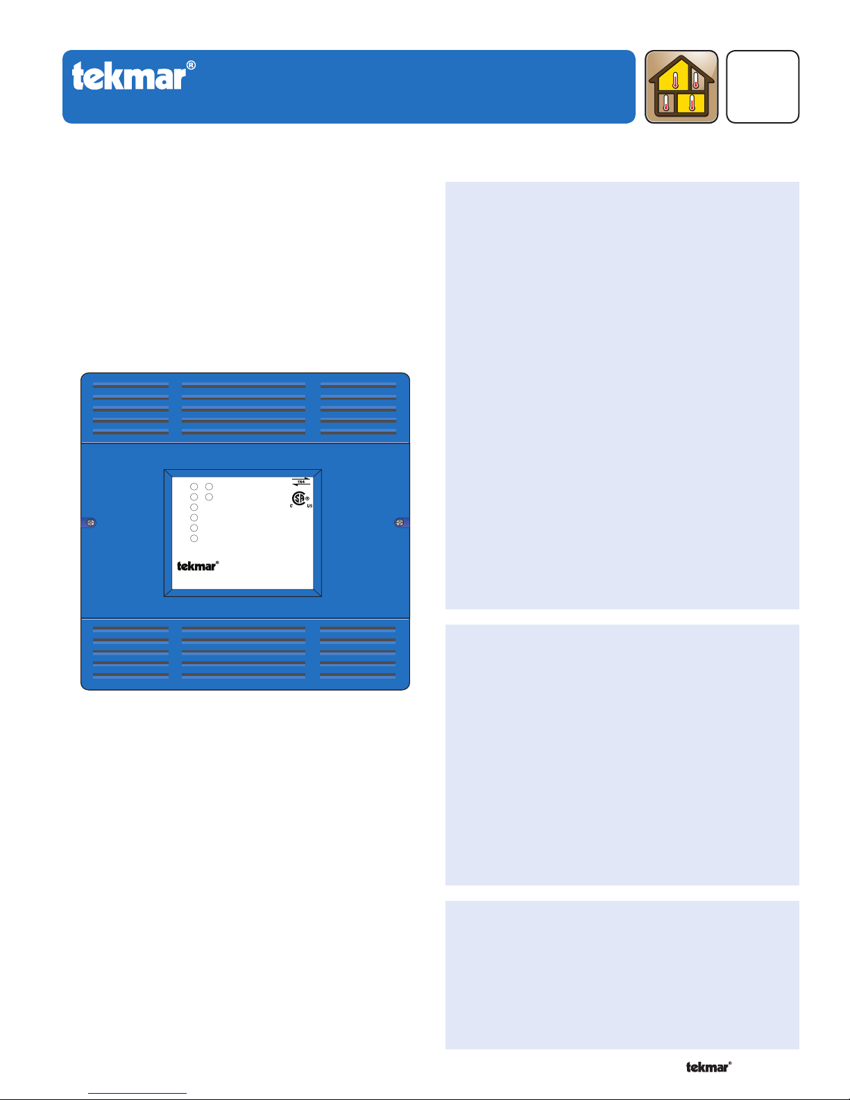
tN4 Wiring Center 315
Introduction
The tekmarNet®4 (tN4) Wiring Center 315 is designed to
operate up to six zone valves in a hydronic heating system.
It can be mounted near a remote zone manifold, providing a
convenient location to wire both thermostats and zone valves
while only requiring two wires to be run back to the mechanical
room. When combined with tekmarNet®4 Thermostats, all
devices communicate to provide a synchronized end switch
that reduces cycling of equipment. A zone group pump
relay is also available to switch a pump.
Zone 1
Power
Zone 2
End Switch/ Zone Group Pump
Zone 3
Zone 4
Zone 5
Zone 6
Zoning
Replaces: 04/09
Features
Six 24 V (ac) powered zone outputs
•
For use with tekmarNet
•
tN4 expansion terminals
•
Isolated end switch
•
Zone group pump relay
•
External diagnostic LEDs
•
CSA C US Certified for use in USA and Canada
•
®
4 Thermostats
D 315
04/11
tN4 Wiring Center 315
Six Zone Valves
Benefi ts
Simple, convenient wiring location
•
Compact enclosure for flexible installation
•
Reduce equipment cycling when combined with
•
tekmarNet®4 Thermostats
Note
Not for use with tekmarNet®2 Thermostats•
1 of 12 © 2011 D 315 - 04/11
Page 2
Table of Contents
---------------------------------------------------------------------------------------
-----------------------------------------------------------------------------------
--------------------------------------------------------------------------------------
Installation ...................................................................... 2
Preparation ................................................................. 2
Physical Dimensions ..................................................3
Installation Location ...................................................3
Rough-In Wiring .........................................................3
Sizing the Transformer ...............................................4
Control Wiring ............................................................4
Testing the Control Wiring ..........................................6
Applic ations .................................................................... 7
User Interface ............................................................... 10
LEDs ........................................................................10
Sequence of Operation ................................................10
tekmarNet® System ..................................................10
Relay Outputs ........................................................... 11
Energy Saving Features ........................................... 11
Troubleshooting ............................................................ 11
Frequently Asked Questions .................................... 11
Technical Data ..............................................................12
Limited Warranty and Product Return Procedure ........12
Getting Started
Congratulations on the purchase of your new tekmarNet
This manual covers the complete installation, programming and sequence of operation for this control. You will also find
instruction on testing, commissioning, and troubleshooting the control and system that it operates.
®
Wiring Center!
Installation
Caution
Improper installation and operation of this control could
result in damage to the equipment and possibly even
personal injury or death. It is your responsibility to ensure
that this control is safely installed according to all applicable
codes and standards. This electronic control is not intended
for use as a primary limit control. Other controls that are
intended and certified as safety limits must be placed into
the control circuit. Do not attempt to service the control.
Refer to qualified personnel for servicing. There are no
user serviceable parts. Attempting to do so voids warranty
and could result in damage to the equipment and possibly
even personal injury or death.
Radio Frequency Interference
The installer must ensure that this control and its wiring are
isolated and/or shielded from strong sources of electromagnetic
noise. Conversely, this Class B digital apparatus complies
with Part 15 of the FCC Rules and meets all requirements of
the Canadian Interference-Causing Equipment Regulations.
However, if this control does cause harmful interference
to radio or television reception, which is determined by
turning the control off and on, the user is encouraged to try
Preparation
Tools Required
tekmar or jeweller screwdriver
•
Phillips head screwdriver
•
Materials Required
(2) #10 x 1” wood screws
•
(2) wire nuts
•
18 AWG LVT solid wire (low voltage connections)
•
Power Required
120 V (ac), 1-phase, 15 A service from circuit breaker
• Power disconnect (optional)•
panel
---------------------------------------------------------------------------------------
-----------------------------------------------------------------------------------
--------------------------------------------------------------------------------------
to correct the interference by re-orientating or relocating
the receiving antenna, relocating the receiver with respect
to this control, and/or connecting the control to a different
circuit from that to which the receiver is connected.
Cet appareil numérique de la classe B respecte toutes
les exigences du Règlement sur le matériel brouilleur du
Canada.
Needle-nose pliers
•
Wire stripper
•
14 AWG solid wire (line voltage connections)
•
tekmar 009 (24 V (ac) transformer)
•
Cable or conduit connectors
•
© 2011 D 315 - 04/11 2 of 12
Page 3
-----------------------------------------------------------------------------------
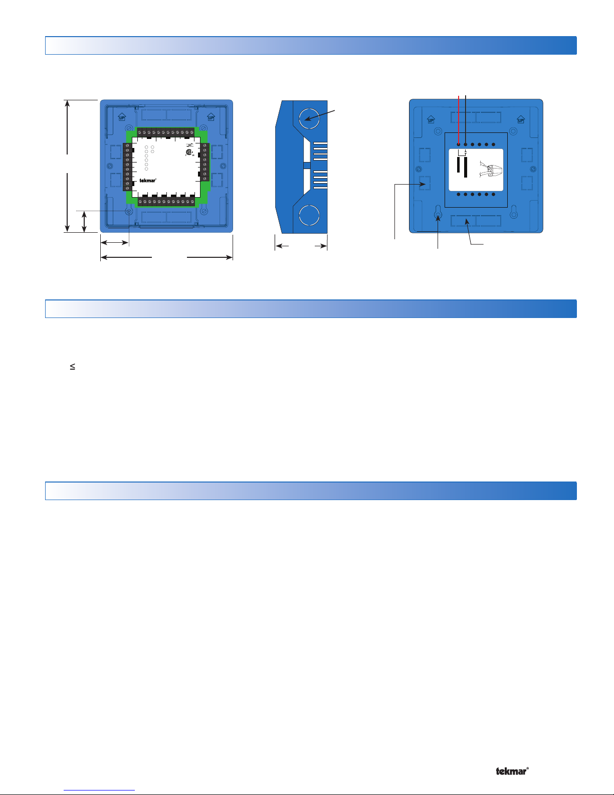
Physical Dimensions
5–1/2”
(140 mm)
Front View
7/8”
C
Zone 2
W tN4CtN4CX
Zone 1
Zone 1 Expansion
Zone 2
Zone 3
Zone 4
Zone 5
Zone 6
End Switch
XC
Input Power
RR
tN4 Wiring Center 315
Six Zone Valves
Zone 1
Zone 2
VlvC
C
WtN4 R
Zone 3
Power
End Switch/ Zone Group Pump
Zone 3
Zone 4
VlvC
VlvC
WtN4 R C
VlvC
WtN4 R
H8001B
Zone 4
Zone 5
RWtN4C
WtN4C
Zone 6
R
Zone 5
Zone 6
(75°C) conductors
Use at least 167°F
VlvC
VlvC
Side View Back View
(22 mm)
CL
1–1/8” (30 mm)
5–1/2”
(140 mm)
Installation Location
When choosing the location for the control, consider the
•
following:
Keep dry. Avoid potential leakage onto the control.
•
RH 90% to 122°F (50°C) in a non-condensing
environment.
Do not expose to operating temperatures beyond 32-
•
122°F (0-50°C).
Provide adequate ventilation.
•
Keep away from equipment, appliances or other sources
•
of electrical interference.
2–1/4”
(57 mm)
1/2” Knock-out (x 4)
315
Strip wires1/2 inch (13 mm).
Installed wires are not removable.
12-18 AWG
7/8” x 1/2” (23 mm x 12 mm)
Knock-out (x 4)
1/2” x 5/8”
(12 mm x 16 mm)
Zone Power L
Ø 1/8” (3 mm)
Zone Group Pump
Knock-out (x 4)
Locate the control near zone valves if possible.
•
Provide easy access for wiring and viewing the
•
control.
Mount approximately 5 ft. (1.5 m) off the finished floor.
•
Install to wall using #10 x 1” wood screws. Wall anchors
•
are recommended when mounting to sheet rock, wallboard or masonry.
Rough-In Wiring
Line Voltage Wiring
In most cases, the control can be mounted directly to a wall
without the need for any line voltage connections.
As an option, the control may be mounted to a 4” x 4”
electrical junction box so that the high voltage electrical
connections for the transformer are safely contained.
For ease of service, the circuit breaker or power disconnect
should be located in reasonably close proximity to the
equipment.
All line voltage wire connections are recommended to
be pulled inside a flexible or solid conduit. Always follow
proper wiring practices, building and electrical codes for
your jurisdiction.
-----------------------------------------------------------------------------------
Each cable must be pulled to the electrical junction box. It
is recommended to label each cable for easy identification.
All line voltage wires should be stripped to a length of 1/2”
(13 mm).
Pull a three conductor 14 AWG cable for the following
equipment:
Circuit Breaker or Power Disconnect (if applicable)
•
Zone Group Pump (if applicable)
•
3 of 12 © 2011 D 315 - 04/11
Page 4
-----------------------------------------------------------------------------------
Low Voltage Wiring
-----------------------------------------------------------------------------------
Each cable must be pulled from the equipment to the
control’s plastic enclosure. All low voltage wiring connections
enter the enclosure through conduit knockouts on the
sides, or through the square knockouts on the rear. It is
recommended to label each cable for easy identification.
All low voltage wires are to be stripped to a length of 3/8”
(9 mm) to ensure proper connection to the control.
Pull two conductor 18 AWG LVT cable, up to 500 feet
(150 m) for the following equipment:
tekmarNet®4 Expansion (if applicable)
•
24 V (ac) Power
•
-----------------------------------------------------------------------------------
Sizing the Transformer
•
Zone Valves
•
Boiler T-T (If using End Switch)
Pull three conductor 18 AWG LVT cable, up to 500 feet
(150 m) for the following equipment:
tekmarNet
•
Pull four conductor 18 AWG LVT cable, up to 500 feet
(150 m) for the following equipment:
•
tekmarNet
®
4 Accessories (User Switch, Timer)
®
4 Thermostats
The control requires an external transformer. A tekmar
Transformer 009 (or 009K which includes a 4”x 4” electrical
box) can supply up to 40 VA, and includes an in-line fuse
to protect the transformer and control.
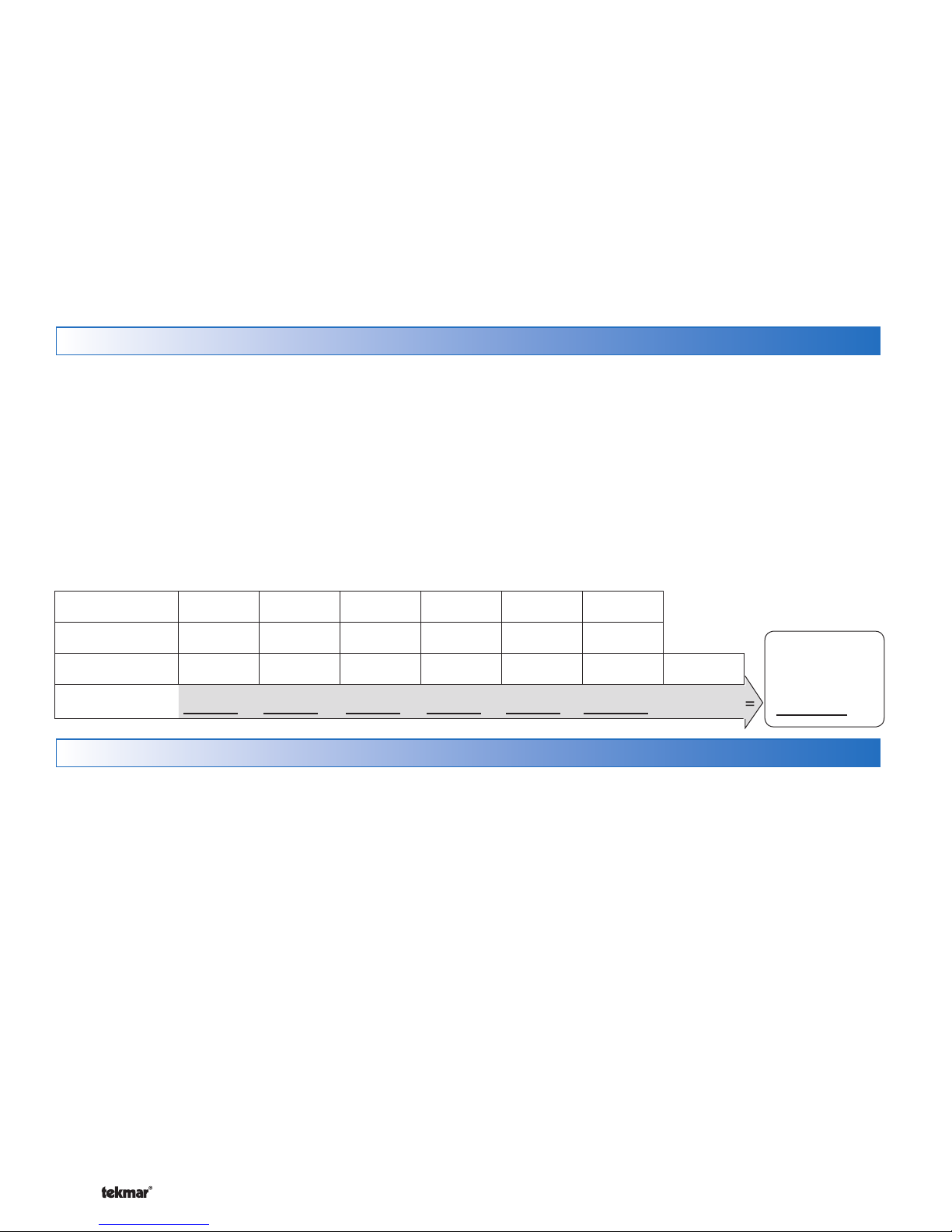
In order to correctly size the external transformer, all loads
connected to the control must be taken into account.
When adding up the loads, consider the following:
tekmarNet®4 Thermostats draw approximately 2 VA each.
•
Each zone valve must be sized for peak load. This can be
•
obtained by multiplying the peak current draw (in Amps)
by 24 V (ac).
Zone
Thermostat Load
Zone Valve Load
Total Zone Load
123456
++++++
The total power capacity of the power supply should be
larger than the total load of all the devices connected to
the control. This total load must not exceed 98 VA. Multiple
tekmar Transformer 009’s can be wired together to increase
total VA capacity.
The following chart is provided to simplify transformer
sizing:
Control Wiring
Line Voltage Wiring
CAUTION: TURN ALL POWER OFF BEFORE PERFORMING ANY WIRING.
-----------------------------------------------------------------------------------
Control
Load (VA)
3
Transformer
must exceed:
VA
Wire the Grounds
Connect the power supply ground and zone group pump
•
ground to the electrical box as shown in Figure 1.
Wire the Neutrals (N)
Connect the 115 V (ac) neutral (N) and zone group pump
•
neutral wires to the 115 V (ac) side of the transformer. Use
a wire nut or approved connector. See Figure 1.
Wire the Power (L)
Connect the 115 V (ac) line voltage (L) wire to the 115 V
•
(ac) side of the transformer and to the Power L wire (red)
of the zone group pump relay. Use a wire nut or approved
connector. See Figure 1.
© 2011 D 315 - 04/11 4 of 12
Wire the Zone Group Pump (L)
Connect the 115 V (ac) line voltage (L) wire from the
•
zone group pump to the Zone Group Pump push-in wire
connector. See Figure 1.
If the zone group pump is not used, then cut the rear red
•
and black wires where they exit the enclosure.
Page 5

Figure 1 - Connect
-----------------------------------------------------------------------------------
---------------------------------------------------------------------------------
Line Voltage Wires
Zone Group
Pump
(L, N, Ground)
Install The Enclosure
The enclosure may be mounted directly to a wall or to
•
an electrical junction box.
Ensure that the high voltage wires are neatly tucked
•
inside the electrical junction box.
Using 2 of the 4 holes in the back of the enclosure, securely
•
fasten it to the electrical junction box with 2 #10 screws as
shown in Figure 2.
Low Voltage Wiring
External Power Supply
It is strongly recommended that a transformer with an in-line
fuse be used in order to protect the transformer from high
currents. The tekmar Transformer 009 includes a fuse.
Connect the 24 V (ac) leads from the transformer to the C
•
and R terminals marked “Input Power” on the 315.
tekmarNet®4 Thermostats
The tN4 Wiring Center 315 is designed to operate with
tekmarNet®4 Thermostats. They provide a synchronized
end switch on the Wiring Center and communicate with
any other tN4 device on the system.
•
Connect the tN4, C, R and W terminals from each
thermostat to the corresponding terminals for each
zone on the Wiring Center.
•
Ensure the tN4 and C wires are not reversed.
Conventional Thermostats
The tN4 Wiring Center 315 may be used with conventional
and ‘power stealing’ type thermostats. However, the end
switch synchronization feature will not be available.
Install the thermostat to the appropriate R and W ter-
•
minals on the 315.
---------------------------------------------------------------------------------
-----------------------------------------------------------------------------------
(red)
Power Source
(L, N, Ground)
Figure 2
Important Note:
Do not mix tekmarNet®4 and conventional thermostats on
the same wiring center.
Zone Valves
Wire the zone valves to the C and Vlv terminals on the 315.
•
End switches on zone valves are not required when
•
using the 315.
tN4 Expansion Terminals (tN4 thermostats only)
The 315 uses the Expansion tN4 and C terminals to communicate
with additional Wiring Centers, House Controls, and other
tekmarNet® devices.
Connect the tN4 and C Expansion terminals on the 315
•
to the corresponding tN4 and C Expansion terminals of
the additional external device.
Wiring the End Switch
The 315 can operate a single on-off boiler or provide a
demand to a tekmar control.
Connect the X X End Switch terminals on the 315 to the
•
T-T (or R-W) terminals on the boiler.
If required, use the X X End Switch terminals to switch
•
24 V (ac) to power a demand on a tekmar outdoor reset
control.
5 of 12 © 2011 D 315 - 04/11
Page 6

Testing the Control Wiring
-----------------------------
------------
------------
----------
----------------------
--------------
--
Testing the Power
If the control Power light does not turn on, check the Input
Power wiring terminals using an electrical multimeter. The
voltage should measure between 21.6 to 26.4 V (ac). If the
voltage is below this range, measure the line voltage side
of the transformer. The voltage should measure between
103.5 to 126.5 V (ac).
Testing tekmarNet®4 Thermostats
1. To test the tN4 Network, check the tN4 and C wires for
continuity.
Disconnect the tN4 and C wires from the tekmarNet®4
•
Wiring Center and twist them together.
Go to the thermostat and disconnect the tN4 and C
•
wires.
Using an electrical test meter, check for continuity.
•
If continuity exists, then proceed to next step, if not,
verify that correct wires are in place prior to continuing to next step.
Reconnect the wires to the proper terminals.
•
2. To test the call for Heat (W), a continuity test is used
between terminals R and W.
Disconnect the wire from terminal W on the 315.
•
When the thermostat calls for heat, the resistance be-
•
tween R and the disconnected W wire should be 0
ohms or tone indicating continuity.
When there is no call for heat the resistance be-
•
tween R and W should be infinite, O.L. or no tone
should be heard.
Testing Conventional Thermostats
To test the call for Heat (W), a continuity test is used
between terminals R and W.
1. Disconnect the wire from terminal W.
2. When the thermostat calls for heat, the resistance
between R and the disconnected W wire should be
less than 7 ohms or tone indicating continuity.
3. When there is no call for heat the resistance between
R and the disconnected W wire should be infinite, O.L.,
or no tone should be heard.
Testing Power-Stealing Thermostats
The tN4 Wiring Center 315 can also accept ‘power-stealing’
type thermostats. They must output less than 5 V (ac) when
not calling for heat, or the 315 may detect a false heat call
and open the corresponding zone valve.
1. Connect the R & W wires from the thermostat to the
desired zone R and W terminals on the 315.
2. When the thermostat is not calling for heat, the
corresponding zone LED should not be lit.
If the zone LED is lit, then a resistor may have to be
•
added to reduce the trickle voltage through the thermostat. See the thermostat installation manual for
details.
-----------------------------
------------
------------
----------
Testing the Zone Output
1. Use an electrical test meter to measure the (ac) voltage
between the C and the Vlv terminals for each zone valve
output.
Lower the thermostat temperature setting. When the
•
zone LED is off, the reading should be 0 V (ac) and the
valve should be closed.
Raise the thermostat temperature setting. When the
•
zone LED is on, the reading should be 24 V (ac) + / –
10% and the valve should be open.
Note: If power to the zone valve is present but the zone
valve does not operate properly, refer to any troubleshooting
information supplied by the zone valve manufacturer.
Testing tekmarNet®4 Expansion
To test the tN4 Network, check the wires for continuity
and shorts.
1. Disconnect the two tN4 expansion wires (tN4 and C)
at one end and twist them together.
2. Go to the other end of the wires and disconnect
them.
3. Using an electrical test meter, check for continuity.
Resistance should read 0 ohms, or continuity should
produce a tone. If not, this indicates that there are
damaged wires connecting the tN4 control to the 315.
Repair or replace them as necessary.
4. Go back to the original end of the wires and, using a
wire nut, cap each expansion wire individually so that
these ends cannot touch another conductor.
5. Go to the other end of the wires and again, test for
shorts. Resistance should be infinite, or O.L. and there
should be no tone. If tone exists or less than 50 000
ohms is found, then the wires are not insulated from
one another. This is generating a short on the wires
connecting the tN4 control to the tN4 Wiring Center.
6. Replace the damaged wires, test, and reconnect them
to their proper terminals.
Testing The End Switch / Zone Group Pump
If the tN4 expansion terminals are not used to connect
the tN4 Wiring Center to the system, the end switch may
be used.
1. Remove the wires from the end switch terminals.
2. Use an electrical test meter to measure continuity
across the XX end switch terminals on the 315.
When the end switch LED is off, no continuity should
•
be present (no tone).
When the end switch LED is on, continuity should be
•
present (tone).
3. Use an electrical test meter to measure voltage across
the zone group pump hot switch leg and neutral.
When the zone group pump LED is off, the voltage
•
should be 0 V (ac).
When teh zone group pump LED is on, the voltage
•
should be between 103.5 to 126.5 V (ac).
----------------------
--------------
--
© 2011 D 315 - 04/11 6 of 12
Page 7

Applications
tekmarNet®4 Expansion to Building Control A315-1
Description: tN4 Wiring Center 315, six tekmarNet®4 Thermostats, and six zone valves wired to a tekmar System Control
420 and 335, which controls the boiler, primary pump and DHW pump and six other zones.
070
420 335
tekmarNet®4
Thermostats
315
Z1
Z2Z3Z4
tekmarNet®4 Thermostats Required
Z5
Z6
tekmarNet
®
Thermostats
4
External
tekmarNet
Expansion to
Zone Manager,
Reset Module, or
House Control
tN4
Expansion
L
N
24 V (ac)
Transformer 009
C tN4
C
C
WtN4 R
Zone 1
Zone 1 Expansion
Zone 2
Zone 3
Zone 4
Zone 5
Zone 6
End Switch
Input Power
Zone 2
Power
End Switch/ Zone Group Pump
®
4
W tN4C tN4CX
XC
RR
Zone 3
WtN4 R C
Zone 4
WtN4 R
H8001B
Zone 5
RW tN4C
W tN4C
Zone 6
R
tN4 Wiring Center 315
Six Zone Valves
Zone 1
Zone 2
Zone 3
Zone 4
Zone 5
VlvC
VlvC
VlvC
VlvC
R
C
Zone 6
VlvC
Zone Valves (Z1 to Z6)
(75°C) conductors
Use at least 167°F
VlvC
7 of 12 © 2011 D 315 - 04/11
Page 8

End Switch (X-X) To Powered Boiler Demand A315-2
Description: tN4 Wiring Center 315, six tekmarNet®4 Thermostats, and six zone valves wired into a powered boiler demand
input on a device such as a tekmar Boiler Control 260 which controls the primary pump and DHW pump.
070
260
(Use tekmarNet
315
Z1
Z2 Z3 Z4 Z5 Z6
®
tekmarNet
®
4 Thermostats to achieve better system performance)
4, or Conventional Thermostats
tekmarNet
®
4 Thermostats
Boiler
Demand
Powered Boiler Demand
L
N
24 V (ac)
Transformer 009
C
Zone 1
Zone 1 Expansion
Zone 2
Zone 3
Zone 4
Zone 5
Zone 6
End Switch
Input Power
Zone 2
WtN4CtN4CX
XC
RR
WtN4 R
Power
End Switch/ Zone Group Pump
WtN4 R C
Zone 3
Zone 4
WtN4 R
H8001B
Zone 5
Zone 6
RW tN4C
WtN4C
R
C
tN4 Wiring Center 315
Six Zone Valves
Zone 1
Zone 2
Zone 3
Zone 4
Zone 5
VlvC
VlvC
VlvC
VlvC
R
C
Zone 6
VlvC
Zone Valves (Z1 to Z6)
(75°C) conductors
Use at least 167°F
VlvC
© 2011 D 315 - 04/11 8 of 12
Page 9

End Switch (X-X) To Boiler Enable (T-T) A315-3
Description: tN4 Wiring Center 315, six tekmarNet®4 Thermostats, and six zone valves wired into the T-T terminals on the
boiler to give an enable. The pump is controlled by the Zone Group Pump output on the 315.
T
T
End Switch (X-X)
to boiler enable (T-T)
(Use tekmarNet
tekmarNet®4, or Conventional Thermostats
315
Z1
®
4 Thermostats to achieve better system performance)
C
WtN4 R
Zone 2
W tN4C tN4CX
Zone 1
Zone 1 Expansion
Zone 2
Zone 3
Zone 4
Zone 5
Zone 6
End Switch
XC
Input Power
RR
tN4 Wiring Center 315
Six Zone Valves
Zone 1
VlvC
C
Zone 3
Power
End Switch/ Zone Group Pump
Zone 2
Zone 3
VlvC
VlvC
Zone 4
tekmarNet®4 Thermostats
Z5
Zone 5
Zone 4
VlvC
Zone 6
Z6
WtN4 R
H8001B
Zone 5
RW tN4C
W tN4C
Zone 6
R
(75°C) conductors
Use at least 167°F
VlvC
Z2Z3Z4
WtN4 R C
VlvC
L
N
24 V (ac)
Transformer 009
N
R
C
G
N
L
115 V (ac)
(black)
(red)
L
to pump grounds
Zone Valves (Z1 to Z6)
315
Zone Group Pump
Power L
9 of 12 © 2011 D 315 - 04/11
Page 10

User Interface
LEDs
ZONE 1
The zone 1 thermostat is calling for heat
and the 24 V (ac) output is energized.
ZONE 2
The zone 2 thermostat is calling for heat
and the 24 V (ac) output is energized.
ZONE 3
The zone 3 thermostat is calling for heat
and the 24 V (ac) output is energized.
ZONE 4
The zone 4 thermostat is calling for heat
and the 24 V (ac) output is energized.
ZONE 5
The zone 5 thermostat is calling for heat
and the 24 V (ac) output is energized.
ZONE 6
The zone 6 thermostat is calling for heat
and the 24 V (ac) output is energized.
POWER
24 V (ac) is being applied to the Wiring
Center to provide it with power.
Wiring Center 315
Zone 1
Zone 2
Zone 3
Zone 4
Zone 5
Zone 6
Power
End Switch / Zone Group Pump
END SWITCH / ZONE GROUP PUMP
At least one of the zone thermostats are
calling for heat and the end switch and zone
group pump relay outputs are closed.
Sequence of Operation
tekmarNet® System
tekmarNet® is a family of products that use communication
to operate the HVAC system in a comfortable and efficient
manner. The Wiring Center is a zoning component in
a tekmarNet® system and requires tekmarNet®4 (tN4)
Thermostats to be directly connected to it.
The tekmarNet®4 (tN4) Expansion terminals can link the
Wiring Center with other tekmarNet® components:
House Controls 400, 401, 402, 403 - Provides boiler and
•
DHW control
Section A
Reset Modules 420, 421, 422, 423
•
Boiler Controls 274, 275
•
Wiring Centers 313, 314, 315, 316 - Add additional zones
•
tN4 Thermostats - Add thermostats
•
tN4 Timer 033 - Adds 4 programmable schedules
•
tN4 User Switch 479 - Provides a system override for
•
vacations and holidays
tN4 Setpoint Control 161, 162 - Control hot tubs, pools
•
and more
© 2011 D 315 - 04/11 10 of 12
Page 11

Relay Outputs
-------------------------
----------------
------------------
----------------------------
--------------------------
-------------------------
Section B
End Switch Operation
The End Switch relay (‘XX’) closes and the end switch
LED turns on. The switch remains closed as long as any
zone is calling for heat. This can provide a boiler demand
to a tekmar reset control, or provide a boiler enable to a
boiler’s TT terminals.
If the Wiring Center is connected to a tN4 bus, all
communication messages will pass through the 315’s tN4
expansion connection. tN4 messages are required in order
to create a boiler demand on a device such as a tekmar
House Control 400.
-------------------------
Energy Saving Features
Network Schedules
Adding a schedule to a tekmarNet® system is both easy
and valuable. A Timer 033 provides scheduling with up to
4 events per day for every tekmarNet® Thermostat. Turning
down the room temperatures when they are unoccupied
reduces boiler on-time and energy consumption which
helps save money and the environment.
One-Touch Economy
A User Switch 479 allows for one-touch overrides of the
system. For example, if leaving the building for vacation,
simply press the “Away” button and all the thermostats
will immediately operate at a lower temperature, instead
of having to walk around the building lowering the heating
----------------------------
--------------------------
24 V (ac) Zone Relay Operation
When a thermostat calls for heat, it sends a message to
the Wiring Center and the corresponding zone LED turns
on. Power is then supplied to the appropriate zone output
as indicated by the LED.
Zone Group Pump Operation
The zone group pump remains on when any zone is calling
for heat.
----------------
------------------
Section C
temperature setting and raising the cooling temperature
setting on each thermostat.
Zone Synchronization
Another feature of the Wiring Center is Zone Synchronization.
In typical zoned systems, the thermostats operate on a
stand-alone basis. This means that a zone turns on and off
as required without any regard for other zones. The net effect
is random operation of the zones causing short cycling of
the heat source. tekmarNet® thermostats communicate to
ensure that their cycles are synchronized. Energy is saved
by ensuring zones requiring heat operate on the same cycle,
therefore reducing short cycling of the boiler.
-------------------------
Troubleshooting
Frequently Asked Questions
Symptom Look For...
Power LED is off Power to control
No central
heating
Single zone over
heating
Single zone under
heating
Zone LEDs If there are no green Zone LEDs, there are no thermostats calling for heat.
System in AWAY
LED shows zone on
LED shows zone off
LED shows zone on
LED shows zone off Check the thermostat to see if it is calling for heat (H1 displayed on the screen).
Corrective Action
Use electrical meter to measure 24 V (ac) voltage on input power R and C
terminals.
During AWAY, the thermostats operate at a lower temperature. Locate a ‘User
Switch’ and set to Normal to resume heating.
Thermostats have a differential of +/- 1.5°F (0.8°C) of the temperature setting.
Due to the display rounding numbers up, heating can appear on when the
temperature is 2°F (1.1°C) above the setting. This is normal operation.
Ensure zone valve terminals measure 0 V (ac). Measuring 0 V (ac) indicates
mechanical zone valve may have failed in the open position. Measuring 24 V
(ac) indicates control relay may have failed.
Ensure zone valve terminals measure 24 V (ac). Measuring 24 V (ac) indicates
mechanical zone valve may have failed in the closed position. Measuring 0 V
(ac) indicates control relay may have failed.
11 of 12 © 2011 D 315 - 04/11
Page 12

Technical Data
tN4 Wiring Center 315 Six Zone Valves
Literature C315, D315, Q315
Control Microprocessor control. This is not a safety (limit) control.
Packaged weight 1.4 lbs (630 g)
Dimensions 5.5” H x 5.5” W x 2.25” D (140 x 140 x 57 mm)
Enclosure Blue PC+ABS plastic, NEMA type 1
Approvals
Ambient conditions Indoor use only, 32 to 122°F (0 to 50°C), RH 90% Non-condensing
Power supply 24 V (ac) ±10% 60 Hz, 3 VA min, 98 VA max, Class 2
Zone valve load 24 V (ac) 2 A, maximum combined current (zones 1 to 6): 4 A
End switch relay 24 V (ac) 2 A
Zone group pump relay 115 V (ac) 5 A, 1/6 hp
Warranty Limited 3 Year
CSA C US, meets class B: ICES & FCC Part 15
Limited Warranty and Product Return Procedure
Limited Warranty The liability of tekmar under this warranty is lim-
ited. The Purchaser, by taking receipt of any tekmar product (“Product”), acknowledges the terms of the Limited Warranty in effect at
the time of such Product sale and acknowledges that it has read
and understands same.
The tekmar Limited Warranty to the Purchaser on the Products sold
hereunder is a manufacturer’s pass-through warranty which the
Purchaser is authorized to pass through to its customers. Under
the Limited Warranty, each tekmar Product is warranted against
defects in workmanship and materials if the Product is installed and
used in compliance with tekmar’s instructions, ordinary wear and
tear excepted. The pass-through warranty period is for a period of
twenty-four (24) months from the production date if the Product is
not installed during that period, or twelve (12) months from the documented date of installation if installed within twenty-four (24) months
from the production date.
The liability of tekmar under the Limited Warranty shall be limited to, at
tekmar’s sole discretion: the cost of parts and labor provided by tekmar
to repair defects in materials and/or workmanship of the defective product; or to the exchange of the defective product for a warranty replacement product; or to the granting of credit limited to the original cost of the
defective product, and such repair, exchange or credit shall be the sole
remedy available from tekmar, and, without limiting the foregoing in any
way, tekmar is not responsible, in contract, tort or strict product liability, for any other losses, costs, expenses, inconveniences, or damages,
whether direct, indirect, special, secondary, incidental or consequential,
arising from ownership or use of the product, or from defects in workmanship or materials, including any liability for fundamental breach of
contract.
The pass-through Limited Warranty applies only to those defective Products returned to tekmar during the warranty period. This Limited Warranty does not cover the cost of the parts or labor to remove or transport
the defective Product, or to reinstall the repaired or replacement Product,
all such costs and expenses being subject to Purchaser’s agreement and
warranty with its customers.
Any representations or warranties about the Products made by Purchaser
to its customers which are different from or in excess of the tekmar Limited Warranty are the Purchaser’s sole responsibility and obligation. Purchaser shall indemnify and hold tekmar harmless from and against any
and all claims, liabilities and damages of any kind or nature which arise
out of or are related to any such representations or warranties by Purchaser to its customers.
The pass-through Limited Warranty does not apply if the returned Product has been damaged by negligence by persons other than tekmar,
accident, fire, Act of God, abuse or misuse; or has been damaged by
modifications, alterations or attachments made subsequent to purchase
which have not been authorized by tekmar; or if the Product was not
installed in compliance with tekmar’s instructions and/or the local codes
and ordinances; or if due to defective installation of the Product; or if the
Product was not used in compliance with tekmar’s instructions.
THIS WARRANTY IS IN LIEU OF ALL OTHER WARRANTIES, EXPRESS
OR IMPLIED, WHICH THE GOVERNING LAW ALLOWS PARTIES TO
CONTRACTUALLY EXCLUDE, INCLUDING, WITHOUT LIMITATION,
IMPLIED WARRANTIES OF MERCHANTABILITY AND FITNESS FOR
A PARTICULAR PURPOSE, DURABILITY OR DESCRIPTION OF THE
PRODUCT, ITS NON-INFRINGEMENT OF ANY RELEVANT PATENTS
OR TRADEMARKS, AND ITS COMPLIANCE WITH OR NON-VIOLATION OF ANY APPLICABLE ENVIRONMENTAL, HEALTH OR SAFETY
LEGISLATION; THE TERM OF ANY OTHER WARRANTY NOT HEREBY
CONTRACTUALLY EXCLUDED IS LIMITED SUCH THAT IT SHALL NOT
EX TEND BEYOND T WENT Y-FOUR (24) MONTHS FRO M TH E PRODU CTION DATE, TO THE EXTENT THAT SUCH LIMITATION IS ALLOWED BY
THE GOVERNING LAW.
Product Warranty Return Procedure All Products that are believed to
have defects in workmanship or materials must be returned, together
with a written description of the defect, to the tekmar Representative
assigned to the territory in which such Product is located. If tekmar
receives an inquiry from someone other than a tekmar Representative,
including an inquiry from Purchaser (if not a tekmar Representative) or
Purchaser’s customers, regarding a potential warranty claim, tekmar’s
sole obligation shall be to provide the address and other contact information regarding the appropriate Representative.
tekmar Control Systems Ltd., Canada, tekmar Control Systems, Inc., U.S.A.
Vernon, B.C. Canada V1B 3K4, 250-545-7749, Fax. 250-545-0650 Web Site: www.tekmarcontrols.com
Product design, software and literature are Copyright © 2011 by:
tekmar Control Systems Ltd. and tekmar Control Systems, Inc.
12 of 12
Head Offi ce: 5100 Silver Star Road,
All specifications are subject to change without notice.
Printed in Canada. D 315 - 04/11.
 Loading...