

Page 1
Installation & Operation Manual
3 41 2
WiFi / Ethernet
Alert Inputs
1 2 3
1 2 3
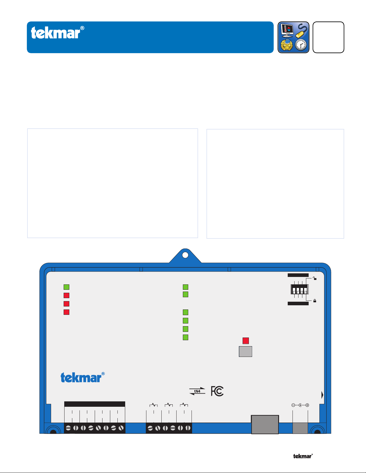
tekmarNet® Internet Gateway 485
Reset
Power: 5 V (dc), 850 mA, Class 2
Alert Inputs: Short or 0 - 32 V (ac)
Designed and assembled in Canada by
tekmar Control Systems Ltd.
1068-01
tN4 Boiler Bus
tN4 Bus 1
tN4 Bus 2
tN4 Bus 3
Power
Alert Input 1
Alert Input 2
Alert Input 3
Date Code
1. Reset IP address: Press and hold 5 sec
2. Reset factory defaults: Press and hold 10 sec
Gateway Ready LED must be on solid before
resetting IP or factory defaults!
WiFi and Ethernet factory default uses DHCP
H2054A
Power
5V (dc)
14133
C1
Bu
s 1
4
tN4
1
C0
Bo
iler Bus
2
tN4
5
C2
Bu
s 2
6
tN47C3
Bu
s 3
8
tN4
Do not appl
y power
Alert
Input 3
1211
Alert
In
put 2
109
Alert
In
put 1
Ethernet
Alert On Br
eak
Alert On Make
Gateway Ready
flashes during startup
WiFi / Ethernet
tekmarNet® Internet Gateway 485
Accessories
485_D
11 /15
Replaces: 12/14
Introduction
The tekmarNet® Internet Gateway 485 allows remote access to tekmarNet® compatible controls through a web browser,
either over the Internet or through a local area network. Users can view and change settings for each thermostat, including:
temperature, heat/cool/auto, fan operation, relative humidity, schedules, and the away scene. In addition, the boiler system
temperatures, firing rate, run times, and pump status can be viewed. All system data can be graphed on a chart or be
exported to a data file. The 485 can send daily or weekly status reports, as well as error and warning notifications, through
e-mail. The 485 includes three alert inputs that can be used to monitor auxiliary equipment.
Featur
WiFi or Ethernet connection to Internet
•
Built-in web server
•
Compatible with computer and mobile phone web browsers
•
View and adjust thermostat settings
•
Monitor hot water system
•
Supports multiple user accounts
•
Graph and export system data
•
Email notification of status and errors
•
Error and warning history log
•
Three alert inputs for equipment monitoring
•
Software updates
•
es
Benefi ts
Reduce energy consumption by remotely controlling
•
and monitoring a building's HVAC system
Notifications can be sent to a service contractor
•
immediately if a problem occurs
All data and information is stored locally on site
•
Pay no monthly or annual fees
•
A Watts Water Technologies Company
1 of
24 © 2015 485_D - 11/15
Page 2
Read t
his Manual BEFORE using this equipment.
Failure to read and follow all safety and use information can result in death, serious personal
injury, property damage, or damage to the equipment.
Keep this Manual available for easy access by all users. Replacement Manuals are available
at tekmarControls.com
Important Safety Information
This is a safety-alert symbol. The safety alert symbol is shown alone or used with a signal word (DANGER,
WARNING, or CAUTION), a pictorial and/or a safety message to identify hazards.
When you see this symbol alone or with a signal word on your equipment or in this Manual, be alert to the
potential for death or serious personal injury.
This pictorial alerts you to electricity, electrocution, and shock hazards.
This symbol identifies hazards which, if not avoided, could result in death or serious injury.
This symbol identifies hazards which, if not avoided, could result in minor or moderate injury.
This symbol identifies practices, actions, or failure to act which could result in property damage or damage
to the equipment.
To avoid serious personal injury and damage to the equipment:
Do not use unless you know the safe and proper operation of this equipment.
•
Improper installation and operation of this control could result in damage to the equipment and possibly even personal
•
injury or death.
This electronic control is not intended for use as a primary limit control. Other controls that are intended and certified as
•
safety limits must be placed into the control circuit.
Do not attempt to service the control. There are no user serviceable parts inside the control. Attempting to do so voids
•
warranty.
It is your responsibility to ensure that this control is safely installed according to all applicable codes and standards. tekmar
•
is not responsible for damages resulting from improper installation and/or maintenance.
Installation must be performed by qualified persons, in accordance with local codes, ANSI/NFPA 70 (NEC Article 424) and
CEC Part 1 Section 62 where applicable. Prior to installation, please consult the local codes in order to understand what is
acceptable. To the extent this information is not consistent with local codes, the local codes should be followed. Please be
aware local codes may require this product and/or the control to be installed by an electrician.
A Watts Water Technologies Company
2 of 24
© 2015 485_D - 11/15
Page 3

T a ble of Contents
Important Safety Information . . . . . . . . . . . . . . . . . . . . . . . . . . . . . . . . . . . . . . . . .....2
Installation . .. . .. . .. . .. .. . .. .. . .. .. . .. . .. .. . .. .. . .. .. . .. .. . .. .. . .. .. . .. . .. .. . .......4
Preparation . . .. . .. .. .. .. .. .. . .. . .. .. .. .. .. .. .. .. .. .. .. .. .. .. .. .. .. .. .. .. .. ..... 4
Physical Dimensions .. . ........ . ........ . ........ . ........ . ........ . ..... 4
Installation Location . . . . . . . . . . . . . . . . . . . . . . . . . . . . . . . . . . . . . . . . . . . . . . . . . . . . . . . 5
Before You Start . .. .. .. ... .. ... .. ... .. ... .. ... .. ... .. ... .. .. .. .. .. .. .. .. ... . 6
Switch Settings . . . . . . . . . . . . . . . . . . . . . . . . . . . . . . . . . . . . . . . . . . . . . . . . . . . . . . . . . . . . . . 6
Status Indicator LED . . . . . . . . . . . . . . . . . . . . . . . . . . . . . . . . . . . . . . . . . . . . . . . . . . . . . . 6
Reset Button . . . . . . . . . . . . . . . . . . . . . . . . . . . . . . . . . . . . . . . . . . . . . . . . . . . . . . . . . . . . . ..... 7
Wiring . . . . . . . . . . . . . . . . . . . . . . . . . . . . . . . . . . . . . . . . . . . . . . . . . . . . . . . . . . . . . . . . . . . . . . . . ..... 7
Wiring to a Thermostat Network ................................... 8
Wiring to a House Control 400, 401, 402, 403 or 406 . . . 9
Wiring to a Universal Reset Module 423 . . . . . . . . . . . . . . . . . . .... 10
Wiring to a Boiler Control 274 or 275............................ 11
Login to the 485 . . . . . . . . . . . . . . . . . . . . . . . . . . . . . . . . . . . . . . . . . . . . . . . . . ........... 12
Router Setup ................................................................ 13
485 Networking ........................................................... 14
Dynamic DNS . . . .. . . . . .. . . . . .. . . .. . . . . .. . . . . .. . . .. . . . . .. . . . . .. . . ............ 15
User Interface . . . . . . . . . . . . . . . . . . . . . . . . . . . . . . . . . . . . . . . . . . . . . . . . . . . . . . . . . . . . . . . . . . . 16
Web Page Configuration ...... . ............. . . ............ ............ 16
Using the Web Pages . . . . . . . . . . . . . . . . . . . . . . . . . . . . . . . . . . . . . . . ............ 19
Troubleshooting . . . . . . . . . . . . . . . . . . . . . . . . . . . . . . . . . . . . . . . . . . . . . . . . . . . . . . . . . . . . . . . 22
Trouble Reaching Login Page . . . . . . . . . . . . . . . . . . . . . . . . . . ............ 22
Trouble Viewing Web Pages .. ......... . ......... . .................. 23
Tec hnical Data . . . . . . . . . . . . . . . . . . . . . . . . . . . . . . . . . . . . . . . . . . . . . . . . . . . . ..............24
Limited Warranty and Product Return Procedure . . . . . . . . . . . . 24
G e tting Started
Congratulations on the purchase of your new tekmarNet® Internet Gateway!
This manual covers the complete installation, programming and sequence of operation for this control. You will also find
instruction on testing, commissioning, and troubleshooting the control and system that it operates.
R a dio Frequency Interference
This equipment has been tested and found to comply with the
limits for a Class B digital device, pursuant to part 15 of the
FCC Rules. These limits are designed to provide reasonable
protection against harmful interference in a residential installation. This equipment generates, uses and can radiate radio
frequency energy and, if not installed and used in accordance
with the instructions, may cause harmful interference to radio
communications. However, there is no guarantee that interference will not occur in a particular installation. If this equipment
does cause harmful interference to radio or television reception,
which can be determined by turning the equipment off and
on, the user is encouraged to try to correct the interference
by one or more of the following measures:
Reorient or relocate the receiving antenna.
•
•
Increase the separation between the equipment and
receiver.
•
Connect the equipment into an outlet on a circuit different
from that to which the receiver is connected.
•
Consult the dealer or an experienced radio/TV technician
for help
Cet appareil numérique de la classe B respecte toutes les exigences du Règlement sur le matériel brouilleur du Canada.
A Watts Water Technologies Company
3 of 24
© 2015 485_D - 11/15
Page 4
Insta
3 412
WiFi / Ethernet
Alert Inputs
1 2 3
1 2 3
tekmarNet® Internet Gateway 485
Reset
Power: 5 V (dc), 850 mA, Class 2
Alert Inputs: Short or 0 - 32 V (ac)
Designed and assembled in Canada by
tekmar Control Systems Ltd.
1068-01
tN4 Boiler Bus
tN4 Bus 1
tN4 Bus 2
tN4 Bus 3
Power
Alert Input 1
Alert Input 2
Alert Input 3
Date Code
1. Reset IP address: Press and hold 5 sec
2. Reset factory defaults: Press and hold 10 sec
Gateway Ready LED must be on solid before
resetting IP or factory defaults!
WiFi and Ethernet factory default uses DHCP
H2054A
Power
5V (dc)
14133
C1
Bus 1
4
tN41C0
Boiler Bus
2
tN45C2
Bus 2
6
tN47C3
Bus 3
8
tN4
Do not appl
y power
Alert
Input 3
1211
Alert
Input 2
109
Alert
Input 1
Ethernet
Alert On Br
eak
Alert On Make
Gateway Ready
flashes during startup
WiFi / Ethernet
llation
Preparation
Contents
tekmarNet® Internet Gateway 485
•
Wall plug power supply
•
5' (1.5 m) Ethernet Cat5-E cable
•
Screwdriver
•
Tools Required
Phillips head screwdriver
•
Needle-nose pliers
•
Materials Required
18 AWG LVT Solid Wire (Low Voltage Connections)
•
4 Wood screws
•
Networking Requirements
-------------------------------- ---------------------------------------------------------------
Installation and Operation Manual 485_D
•
Quick Setup Guide 485_Q
•
- - - -- - - - - - - - - - -- - - - - - - - - - -- - - - - - - - - - -- - - -------------------------------------------------
Wire stripper•
-- --- ----- --- --- ----- --- --- ----- --- --------------------------------------------------
Tab let or Laptop computer (during installation)
•
- - - - - - - - - - - - - - - - - - - - - - - - - - - - - -------------------------------------------------
The 485 must be connected to a router or a network switch. An internet connection is require if access outside of the
building is required. The router must support WiFi 802.11 n, 2.4 GHz, WPA2 encryption.
Web Browsers
- - - - - - - - - - - - - - - - - - - - - - - - - - - - - - - - - - - - - - - - - -------------------------------------------------
The 485 requires HTML5 compatible web browsers. This includes most modern web browsers.
Compatibility
- - - - - - - - - - - - - - - - - - - - - - - - - - - - - - - - - - - - - - - - - - -------------------------------------------------
The 485 is compatible with the following tekmarNet® products manufactured during and after December 2014. Please
contact tekmar customer service to check for compatibility of products manufactured prior to this date. The 485 software
is designed to update. This allows the 485 to be compatible with newly released products not included in this list.
tekmarNet®4 Timer 033
•
tekmarNet®4 Setpoint Control 161, 162
•
Boiler Control 274, 275, 284
•
tN2 Wiring Center 313, 314
•
tN4 Wiring Center 315, 316
•
Zone Expansion Module 324, 325, 326
•
Zone Manager 334, 335, 336, 337
•
Power Manager 345, 346
•
tN2 House Control 400, 401, 402, 403, 406
•
Boiler Reset Control 420
•
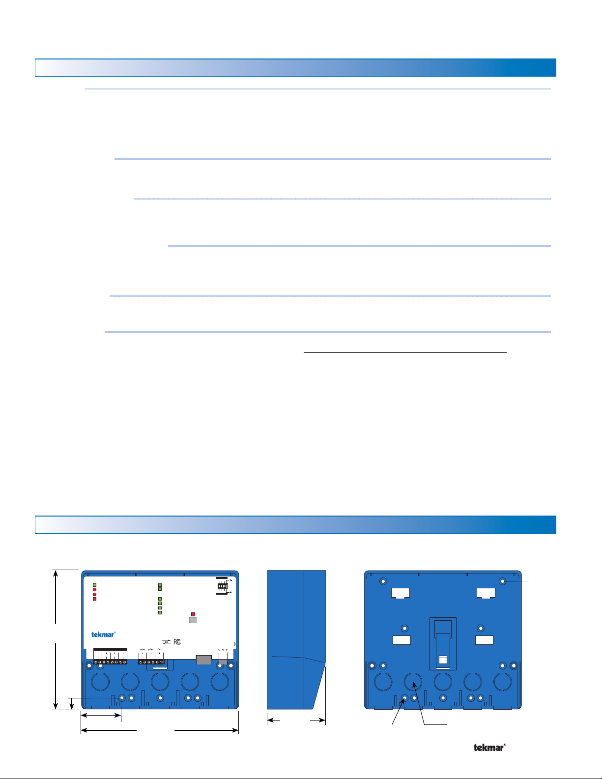
Physical Dimensions
Front V
iew
6–5/8"
(170 mm)
Mixing Reset Control 421
•
Universal Reset Module 422, 423
•
Mixing Expansion Module 440, 441, 444
•
tN4 User Switch 479, 480, 481
•
tekmarNet®2 Thermostat 527, 528, 529, 530
•
tekmarNet®4 Thermostat 537, 538, 540
•
tekmarNet®4 Thermostat 541, 542, 543, 544, 545, 546
•
tekmarNet® Thermostat 532, 552, 553, 554, 557
•
Snow Melt Control 654
•
Side View
Mounting Base
1/2"
(13 mm)
CL
CL
7/8"
(23 mm)
1/2"
(14 mm)
A Watts Water Technologies Company
1–7/8" (49 mm)
7–9/16"
(193 mm)
2–13/16"
(72 mm)
4 of 24
Ø 3/16" (5 mm)
1/2" Knock-out
(x 5 back) (x 5 bottom)
© 2015 485_D - 11/15
Page 5
Installation Location
When choosing the location for the control, consider the
following:
Interior Wall.
•
Keep dry. Avoid potential leakage onto the control.
•
Relative Humidity less than 90%. Non-condensing
•
environment.
No exposure to extreme temperatures beyond 32 to
•
122°F (0 to 50°C).
Away from equipment, appliances, or other sources of
•
electrical interference.
Mounting
Easy access for wiring, viewing.
•
Approximately 5 feet (1.5 m) off the finished floor.
•
The maximum length of wire is 500 feet (150 m).
•
Strip wire to 3/8" (10 mm) for all terminal connections.
•
Use standard 8 conductor, 18 AWG wire.
•
Ethernet cable maximum length is 328 feet (100 m).
•
WiFi maximum distance is 100 feet (30 m) line of sight
•
with no walls. Walls reduce WiFi range.
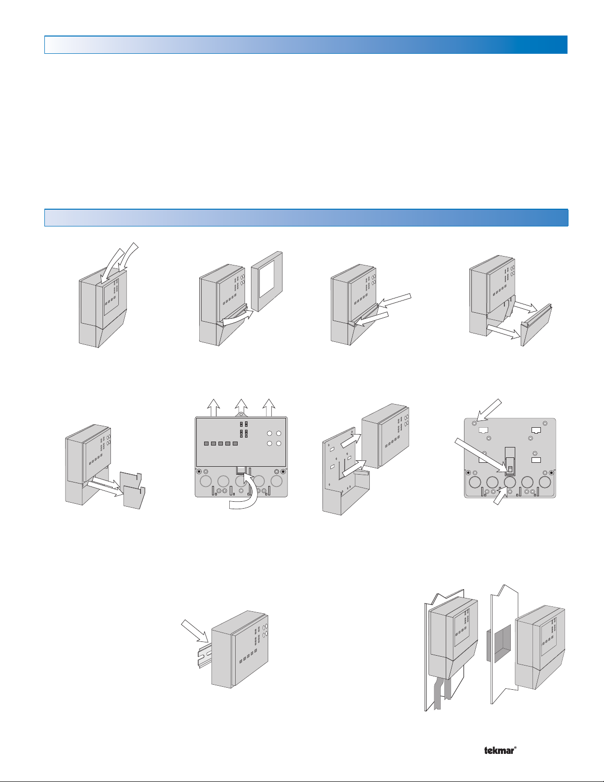
Press down at the fingertip
grips on top of the front cover
and pull out and down.
Remove the safety dividers
from the wiring chamber by
pulling them straight out of
their grooves.
The control can be mounted on
a standard DIN rail. First remove
the control from its base and then,
using the hooks and spring clip
on the back of the control, mount
it onto the DIN rail. This will be
a popular option for those who
prefer to mount the control inside
a larger electrical panel.
Lift the front cover up and
away from the control.
Control release clip
Press the control release
clip on the base inside the
wiring chamber and slide
the control upwards.
The wiring can enter the bottom or
the back of the enclosure. Knockouts provided in the base allow
the wiring to be run in conduit up
to the enclosure. The base also
has holes that line up with the
mounting holes of most common
electrical boxes.
Loosen the screws at the
front of the wiring cover.
The control lifts up and
away from the base.
The wiring cover pulls straight
out from the wiring chamber.
13 Mounting holes
Control
release
clip
There are 10 conduit knock-outs at the back
and bottom of the wiring chamber.
The base is ready for mounting.
A Watts Water Technologies Company
5 of 24
© 2015 485_D - 11/15
Page 6
Before You Start
3 41 2
Alert Inputs
1 2 3
1 2 3
Alert On Break
Alert On Make
Before connecting the tekmarNet® Internet Gateway 485 to
a tekmarNet® system, it is recommended that the system be
fully completed, with no tekmarNet® thermostats or setpoint
controls being added or removed at a later date. Also, each
tekmarNet® thermostat and setpoint control device is automatically assigned a tekmarNet® address when connected to the
system. It is recommended that each device be given a manual
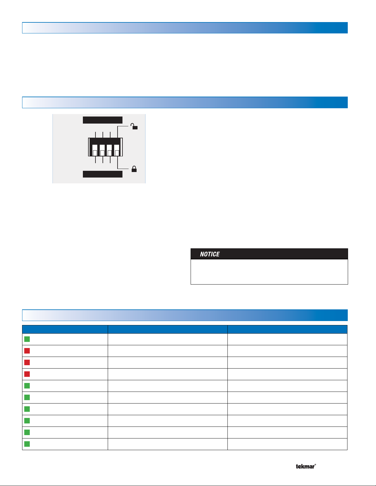
Switch Settings
Inputs
Alert
The 485 has 3 alert inputs. Each alert input has a corresponding alert input switch setting.
Alert on Make
When set to Alert on Make, the 485 will trigger an email
notification when the alert demand input has a contact
closure or a voltage from 0 to 32 V (ac). The alert is cleared
when the alert input has an open contact or the voltage is
removed.
Alert on Break
When set to Alert on Break, the 485 will trigger an email
notification when the alert input has an open contact. The
alert is cleared when the alert input has a contact closure
or a voltage from 0 to 32 V (ac) is applied.
address. This address should be written down together with
the room location for future reference.
The gateway records the address of each tekmarNet® thermostat
and setpoint control. For each address, the installer can name
the room location and building area for each thermostat and
setpoint control.
Unlock / Lock
The Unlock / Lock switch allows the use of a factory default
user ID and password for the 485 login web page.
When set to Unlock (switch setting in up position), the
user ID is “installer” and the password is “tekmar”.
After logging in to the tekmarNet® gateway login web page,
create personal accounts for yourself and your customer
through the configuration page. Once the personal accounts
are completed, the Unlock / Lock switch can be set to
Lock. The default user ID and password are then no longer
accepted.
Should the personal account user ID or passwords be forgotten, the Unlock / Lock switch can be set to Unlock and the
default user ID and password can be used to create new
personal accounts.
Once the tekmarNet® Gateway installation is complete, it is
important that the switch setting be left in the Lock position
in order to prevent unauthorized access.
Status Indicator LED
LEDs On Off
Power
Alert Input 1
Alert Input 2
Alert Input 3
Gateway Ready
WiFi / Ethernet
tN4 Boiler Bus
tN4 Bus 1
tN4 Bus 2
tN4 Bus 3
A Watts Water Technologies Company
Power is on Power is off
Alert input 1 is present Alert input 1 is not present
Alert input 2 is present Alert input 2 is not present
Alert input 3 is present Alert input 3 is not present
Web server operational Web server is offline
Communication to the router No communication to the router
tN4 communication on the boiler bus No tN4 communication on the boiler bus
tN4 communication on bus 1 No tN4 communication on bus 1
tN4 c
ommunication on bus 2 No tN4 communication on bus 2
ommunication on bus 3 No tN4 communication on bus 3
tN4 c
6 of 24
© 2015 485_D - 11/15
Page 7
Reset Button
Switch
11109
Alert
Input 1
Switch
11109
Alert
Input 1
1
C0
Boiler Bus
2
tN4
C tN4
The Reset button has two operations based upon the length
of time the button is held down. The "Gateway Ready" LED
must be on in order for the reset to function.
Reset IP Settings
Press and hold the reset button for 5 seconds. The reset
LED will turn red. The 485 defaults to use DHCP (automatic
addressing) provided by the router. After resetting the IP to the
factory default, the 485 restarts. It may take up to 5 minutes
before web pages are available.
Wiring
Disconnect all power before opening the control.
To prevent the risk of personal injury and/or death, make sure power is not applied to the product until it
is fully installed and ready for final testing. All work must be done with power turned off to the circuit being
worked on.
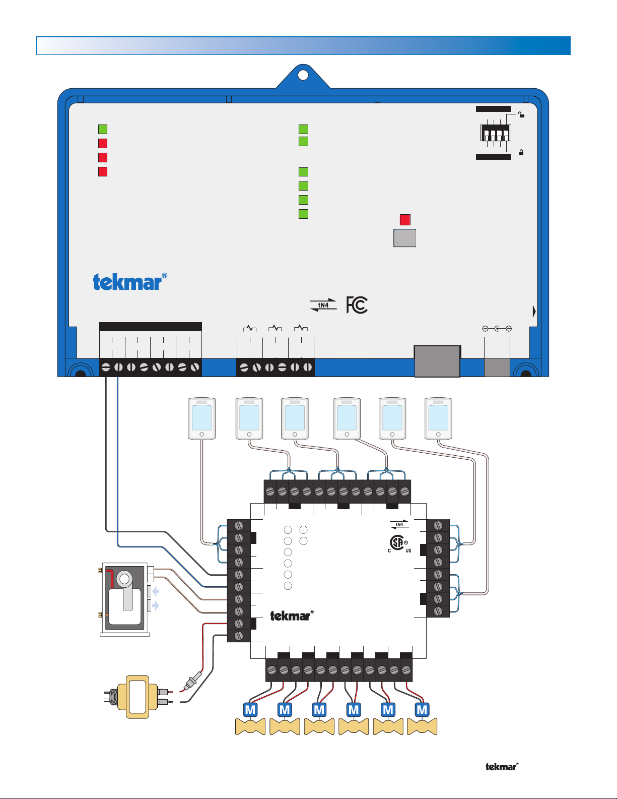
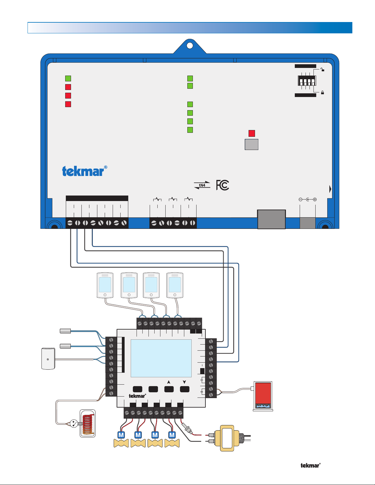
tekmarNet® Bus
The 485 includes four tekmarNet® bus inputs. The tN4
bus inputs allow communication between the 485 and the
tekmarNet® system. Each tN4 bus on the tekmarNet® system
must be wired to the tN4 bus inputs on the 485. The tN4
bus may be wired before or after the control is powered on
and setup.
----------------------------------------------------------------------------------------
Reset Factory Defaults
Press and hold the reset button for 10 seconds. The 485 will
erase all memory and all files will be reset to their factory
defaults. It may take up to 5 minutes before web pages are
available.
Do not disconnect power when resetting the IP address or
resetting the factory defaults. This will result in permanenent
damage to the 485.
All available tN4 buses must be wired to the 485
whether or not there are thermostats connected
to the bus.
Alert
Inputs
--------------------------------------------------------------------------------------------
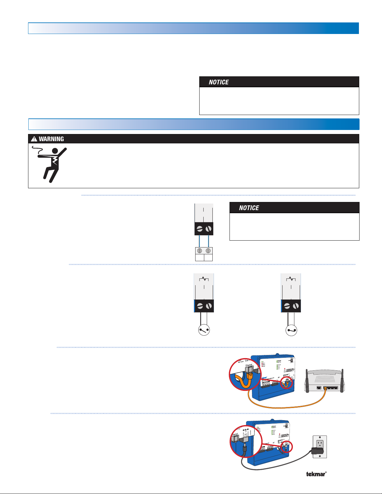
The 485 includes three alert inputs. The alert inputs can be
used to monitor heating equipment for problems such as:
Low water cut off
•
Heating oil or propane tank low tank level
•
Loss of utility electrical power
•
Boiler flame failure lockout
•
Ethernet
- - - - - - - - - - - - - - - - - - - - - - - - - - - - - - - - - - - - - - - - - - - - - ---------------------------------------------------
The 485 must be connected to a router during the initial
installation. After setup has been completed, the 485 may
be connected to a WiFi wireless network.
Power
-- --- --- --- --- --- ---- --- --- --- --- --- ---- --- --- ----------------------------------------------------
The 485 includes a wall plug power supply.
Conne
•
ct the small round end into the power receptacle on
the 485.
•
Plug the wall plug into a 120 V (ac) power receptacle.
The Powe
r status LED will be illuminated green.
DIP Switch: Alert
on Make
Switch is normally
•
open
Alert is sent when
•
switch is closed
DIP Switch: Alert
on Break
Switch is normally
•
closed
Alert is sent when
•
switch is opened
A Watts Water Technologies Company
7 of 24
© 2015 485_D - 11/15
Page 8
Wiring to a Thermostat Network
R
C
L
N
T
T
Power
Zone 1
Zone 2
Zone 3
Zone 4
Zone 5
Zone 6
End Switch/ Zone Group Pump
C
Zone 2
WtN4 R C
Zone 3
WtN4 R C
Zone 4
WtN4 R
tN4 Wiring Center 315
Six Zone Valves
W tN4C tN4C X
Zone 1 Expansion
VlvC
Zone 1
VlvC
Zone 2
VlvC
Zone 3
VlvC
Zone 4
VlvC
Zone 5
VlvC
Zone 6
X C
Input Power
RR
W tN4C
Zone 5
RW tN4C
Zone 6
R
H8001B
End Switch
Use at least 167°F
(75°C) conductors
3 41 2
WiFi / Ethernet
Alert Inputs
1 2 3
1 2 3
tekmarNet® Internet Gateway 485
Reset
Power: 5 V (dc), 850 mA, Class 2
Alert Inputs: Short or 0 - 32 V (ac)
Designed and assembled in Canada by
tekmar Control Systems Ltd.
1068-01
tN4 Boiler Bus
tN4 Bus 1
tN4 Bus 2
tN4 Bus 3
Po
wer
Alert Input 1
Alert Input 2
Alert Input 3
Date Code
1. Reset IP address: Press and hold 5 sec
2. Reset factory defaults: Press and hold 10 sec
Gateway Ready LED must be on solid before
resetting IP or factory defaults!
WiFi and Ethernet factory default uses DHCP
H2054A
Power
5V (dc)
14133
C1
Bus 1
4
tN4
1
C0
Boiler Bus
2
tN4
5
C2
Bus 2
6
tN47C3
Bus 3
8
tN4
Do not apply power
Alert
Input 3
1211
Alert
Input 2
109
Alert
Input 1
Ethernet
Alert On Br
eak
Alert On Make
Gateway Ready
flashes during startup
WiFi / Ethernet
Thermostats
Boiler
A Watts Water Technologies Company
Transformer
8 of 24
Zone Valves
© 2015 485_D - 11/15
Page 9
Wiring to a House Control 400, 401, 402, 403 or 406
R
C
L
N
1
Menu
House Control 402
Item
+
Mix ComBoil Out DHW
VlvC VlvC VlvC
Zone 3Zone 1 Zone 2 Zone 4
Made in Canada
VlvC
Com
Zone 1
H8007B
Zone 2 Zone 3 Zone 4
tN2 tN2 tN2 tN2 tN2 tN2 tN2 tN2 C
Floating Action
ClsOpn
Sensors - No Power
Call Call
tN4 tN4C C
Mod dc/mA Boil Exp. Mix Exp.
Setpoint DHW
Use at least 167°F
(75°C) conductors
RC
Input Power
Stage 2Stage 1
3 41 2
WiFi / Ethernet
Alert Inputs
1 2 3
1 2 3
tekmarNet® Internet Gateway 485
Reset
Power: 5 V (dc), 850 mA, Class 2
Alert Inputs: Short or 0 - 32 V (ac)
Designed and assembled in Canada by
tekmar Control Systems Ltd.
1068-01
tN4 Boiler Bus
tN4 Bus 1
tN4 Bus 2
tN4 Bus 3
Po
wer
Alert Input 1
Alert Input 2
Alert Input 3
Date Code
1. Reset IP address: Press and hold 5 sec
2. Reset factory defaults: Press and hold 10 sec
Gateway Ready LED must be on solid before
resetting IP or factory defaults!
WiFi and Ethernet factory default uses DHCP
H2054A
Power
5V (dc)
14133
C1
Bus 1
4
tN4
1
C0
Boiler Bus
2
tN4
5
C2
Bus 2
6
tN47C3
Bus 3
8
tN4
Do not apply power
Alert
Input 3
1211
Alert
Input 2
109
Alert
Input 1
Ethernet
Alert On Br
eak
Alert On Make
Gateway Ready
flashes during startup
WiFi / Ethernet
Thermostats
Mix Sensor
Boiler Sensor
Outdoor Sensor
DHW Tank
A Watts Water Technologies Company
Zone Valves
Transformer
9 of 24
Boiler
© 2015 485_D - 11/15
Page 10
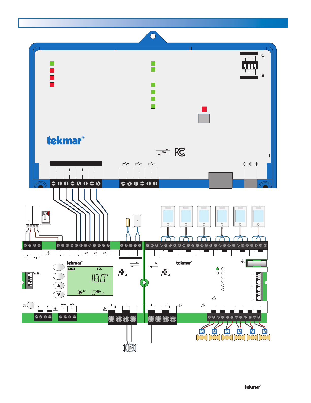
Wiring to a Universal Reset Module 423
50
51 52 53
Stage1/ Stage 2/
Boil Enbl Setp Enbl
75
76 77 78
Demand Demand
DHW Setpoint
54 55
DHW Primary
10 A
max
79 80 81 82
N
Pump NPump
tN4
Made in Canada
8 VA 1 VA
Boil Sens Sup / Ret
H7010A
Off / DHW Sensor
Off / tekmar Stager
Boilers On-Off / Mod
Off / Rotation
Meets Class B: Canadian
ICES & FCC Part 15
Powered
Outputs
24 V (ac)
Universal Reset Module 423
Item
Menu
tektra 1006 -01
Demands: 20 - 260 V (ac)
Relay Rating: 115 V (ac) 5 A
71
72 73 74
DHW 24 V (ac)
/
57 58 59 60 6156
CCtN4
Mod2 (dc)Mod1 (dc)
6564
C3C1+ –C+ –
tN4
62 63
C2 tN4 tN4
66 67
DHW
Com
Boiler
68 69
Boil Com70Out
Do not apply power
Tes t
1 2 3
Vlv R
Zone Manager 335
Meets Class B:
Canadian ICES &
FCC Part 15
Made in Canada
Zone A1
Zone A2
Power
Zone Group Pump A
Zone A3
Zone A4
Zone A5
Zone A6
tN4
tektra 996-01
For product instructions, see brochure
Input Power: 115 V (ac) ±10% 60 Hz 12 A
Relay Rating: 115 V (ac) 5 A
All Loads Using Input Power: 11.5 A
Caution! Disconnect All
Power before Opening
Limited power available, see wiring brochure
For product literature:
www.tekmarcontrols.com
1
2 3 4 5 6 7 8 9 10 11 12 13 14 15 16 20
H7003B
32 33 34 35 36 37 38 39 40 41 42 43
17 18 19 21 22 23 242526 27
24 V (ac) Fuse: T2.5 A 250 V
28 29 30 31
On/Off
Zone Group
Pump A Delay
Zone Group
Pump A
A1
A2
A3
A4
A5
A6
A1
A2
A3
A4
A5
A6
tN4 C C CW WR RPmp tN4 tN4 C WRtN4 C WR RtN4 C WtN4 RC WtN4
Input Power Zone Group Zone A1 Zone A2 Zone A3 Zone A4 Zone A5 Zone A6
Zn Grp A A tNt Zone A1 tNt Zone A2 tNt Zone A3 tNt Zone A4 tNt Zone A5 tNt Zone A6
N
L
N
Pmp A
C
VlvCVlvCVlvCVlvCVlvCVlv
Supply /signal wires 90°C min.
Stage
Modulating
+–T
T
L
115 V (ac)
N
3 41 2
WiFi / Ethernet
Alert Inputs
1 2 3
1 2 3
tekmarNet® Internet Gateway 485
Reset
Power: 5 V (dc), 850 mA, Class 2
Alert Inputs: Short or 0 - 32 V (ac)
Designed and assembled in Canada by
tekmar Control Systems Ltd.
1068-01
tN4 Boiler Bus
tN4 Bus 1
tN4 Bus 2
tN4 Bus 3
Po
wer
Alert Input 1
Alert Input 2
Alert Input 3
Date Code
1. Reset IP address: Press and hold 5 sec
2. Reset factory defaults: Press and hold 10 sec
Gateway Ready LED must be on solid before
resetting IP or factory defaults!
WiFi and Ethernet factory default uses DHCP
H2054A
Power
5V (dc)
14133
C1
Bus 1
4
tN4
1
C0
Boiler Bus
2
tN4
5
C2
Bus 2
6
tN47C3
Bus 3
8
tN4
Do not apply power
Alert
Input 3
1211
Alert
Input 2
109
Alert
Input 1
Ethernet
Alert On Br
eak
Alert On Make
Gateway Ready
flashes during startup
WiFi / Ethernet
Boiler
A Watts Water Technologies Company
Boiler
Sensor
Primary Pump
Outdoor
Sensor
10 of 24
Thermostats
Zone Valves
© 2015 485_D - 11/15
Page 11
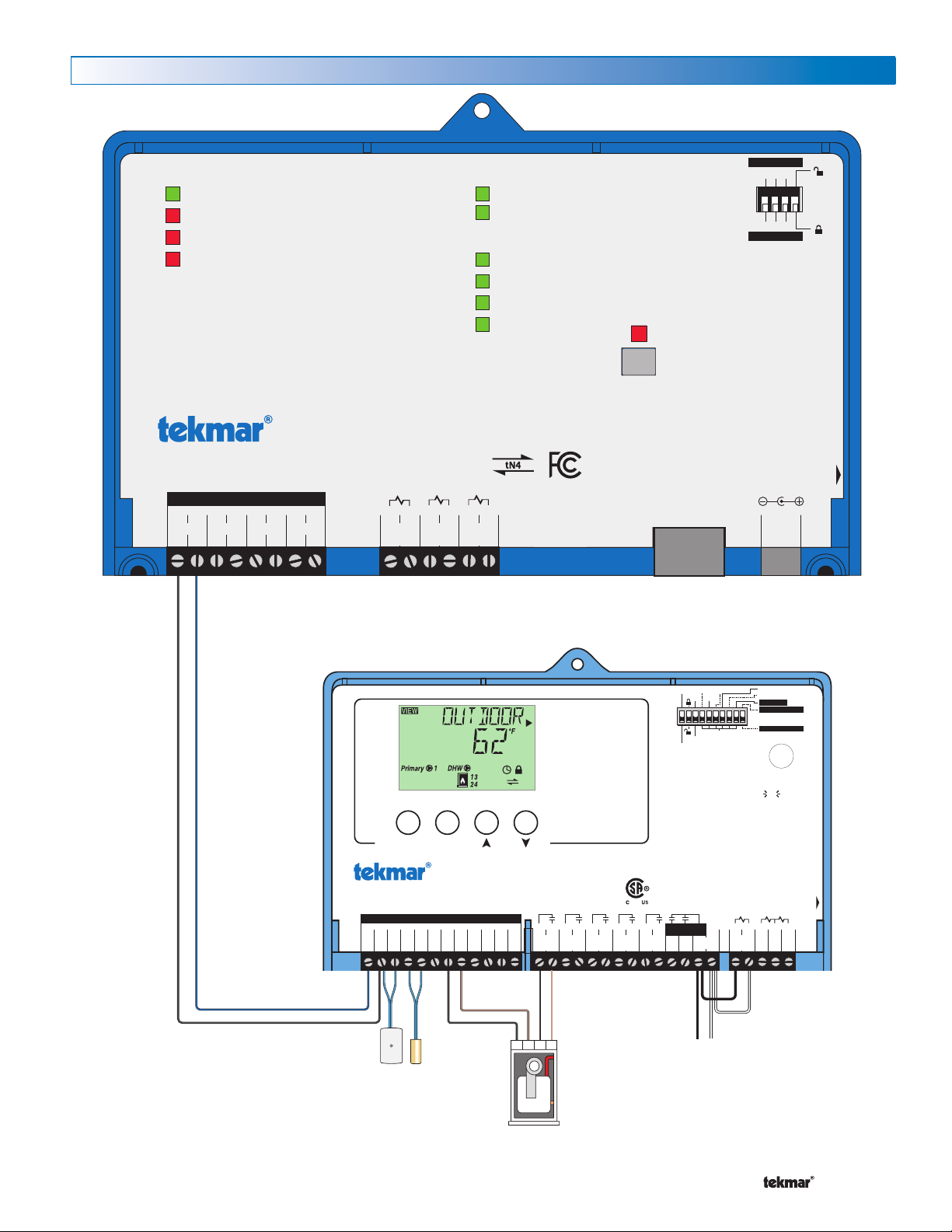
Wiring to a Boiler Control 274 or 275
Setback
Boiler Control 275
One tN4, Four Modulating Boiler & DHW / Setpoint
Menu Item
Tes t
Boiler Demand
DHW / Setpoint Demand
Proof Demand
EMS Input Signal
Priority Override
Power 115 V ±10% 60 Hz 7 VA, 1150 VA max.
Relays 230 V (ac) 5 A 1/3 hp
Demands 20 to 260 V (ac) 2 VA
Designed and assembled in Canada by
tekmar Control Systems Ltd
tektra 1020-01
Meets Class B:
Canadian ICES
FCC Part 15
For maximum heat,
press and hold Test
button for 3 seconds.
not testing
testing
testing paused
off
red
red
BTC I
Off
EMS
Rotate
Fixed Last
Pump Sequencer
Exercise
Off
Demands
Date Code
H2048B
Signal wiring must be rated at least 300 V.
DHW
29
/Setp
Com
30
Dem
Pr.
31
Dem
2
–
5
–
Mod1
1
+
Mod2
3
+
–
+
Mod3
4
+
Mod4
6
+
BRet/
7
Com
8
tN4
12
Boil
9
Out10Com
11
Prim
P1 L N
26
Power
28271413
Do not apply power
24
DHW
/ P2
23 251615 1817 2019 2221
Fixed Lead
First On / Last Off
First On / First Off
Relay1Relay2Relay3Relay4C.A. /
Alert
Boiler
Demand
Sup
DHW
Zone Load Shedding
T T
-
+
L
115 V (ac)
N
3 41 2
WiFi / Ethernet
Alert Inputs
1 2 3
1 2 3
tekmarNet® Internet Gateway 485
Reset
Power: 5 V (dc), 850 mA, Class 2
Alert Inputs: Short or 0 - 32 V (ac)
Designed and assembled in Canada by
tekmar Control Systems Ltd.
1068-01
tN4 Boiler Bus
tN4 Bus 1
tN4 Bus 2
tN4 Bus 3
Po
wer
Alert Input 1
Alert Input 2
Alert Input 3
Date Code
1. Reset IP address: Press and hold 5 sec
2. Reset factory defaults: Press and hold 10 sec
Gateway Ready LED must be on solid before
resetting IP or factory defaults!
WiFi and Ethernet factory default uses DHCP
H2054A
Power
5V (dc)
14133
C1
Bus 1
4
tN4
1
C0
Boiler Bus
2
tN4
5
C2
Bus 2
6
tN47C3
Bus 3
8
tN4
Do not apply power
Alert
Input 3
1211
Alert
Input 2
109
Alert
Input 1
Ethernet
Alert On Br
eak
Alert On Make
Gateway Ready
flashes during startup
WiFi / Ethernet
A Watts Water Technologies Company
Outdoor
Sensor
Boiler
Supply
Sensor
11 of 24
Boiler
© 2015 485_D - 11/15
Page 12
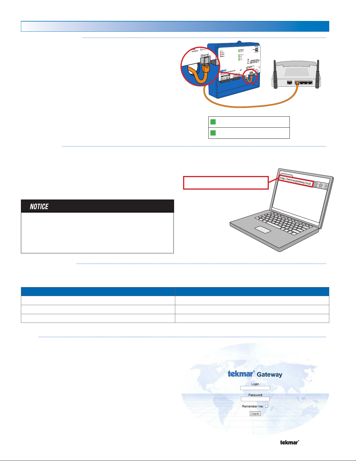
Login to the 485
Network and Power
Using the supplied Ethernet cable, plug the 485 into one of the
LAN ports on a router. Then, using the supplied wall power
supply, plug the small end into the 485 power jack. Lastly,
connect the wall power supply into a wall power outlet.
When the power is first turned on, the 485 may take up to
5 minutes to start up. The web pages are available once
the Gateway Ready and WiFi / Ethernet LEDs are on.
Web Address
On a computer, tablet, or phone connected to the Local Area
Network (LAN), open a web browser.
In the web browser address bar, enter the following address:
http://tekmargateway.local
The tekmar Gateway login page will appear.
- - - - - - - - - - - - - - - - - - - - - - - - - - - - - - - - - - - - - - - - - - -------------------------------------------------
------------------------------------------------------------------------------------
Gateway Ready
WiFi / Ethernet
http://tekmargateway.local
Unicast routers do not support this method of locating the 485
on the network. In this case, login to the router's setup page
and the router will list tekmargateway as one of the devices
on the network. Click this link or enter this IP address into the
web browser to access the 485 login page.
ple Gateways
Multi
There may be cases where there are two or more gateways
installed on the same LAN.
Gateway Startup Sequence Web Address (on LAN only)
1st to start tekmargateway.l ocal
2nd to start tekmargateway-2.local
3rd to start tekmargateway-3.local
- - - - - -- -- -- - -- -- -- - -- -- -- -- - -- -- -- - -- -- -- - -- -- -- - --------------------------------------------------
Login
Make sure the Unlock / Lock switch is set to Unlock. This
enables the use of the default login and password.
Now enter the default login and password.
The default login is installer
•
The default password is tekmar
•
After creating personalized user login accounts, it is highly
recommended to set the Unlock / Lock switch to the Lock
position to prevent unauthorized access.
Make sure to record your login and password for future
reference.
- - - - - - - - - - - - - - - - - - - - - - - - - - - - - - - - - - - - - -------------------------------------------------
A Watts Water Technologies Company
12 of 24
© 2015 485_D - 11/15
Page 13
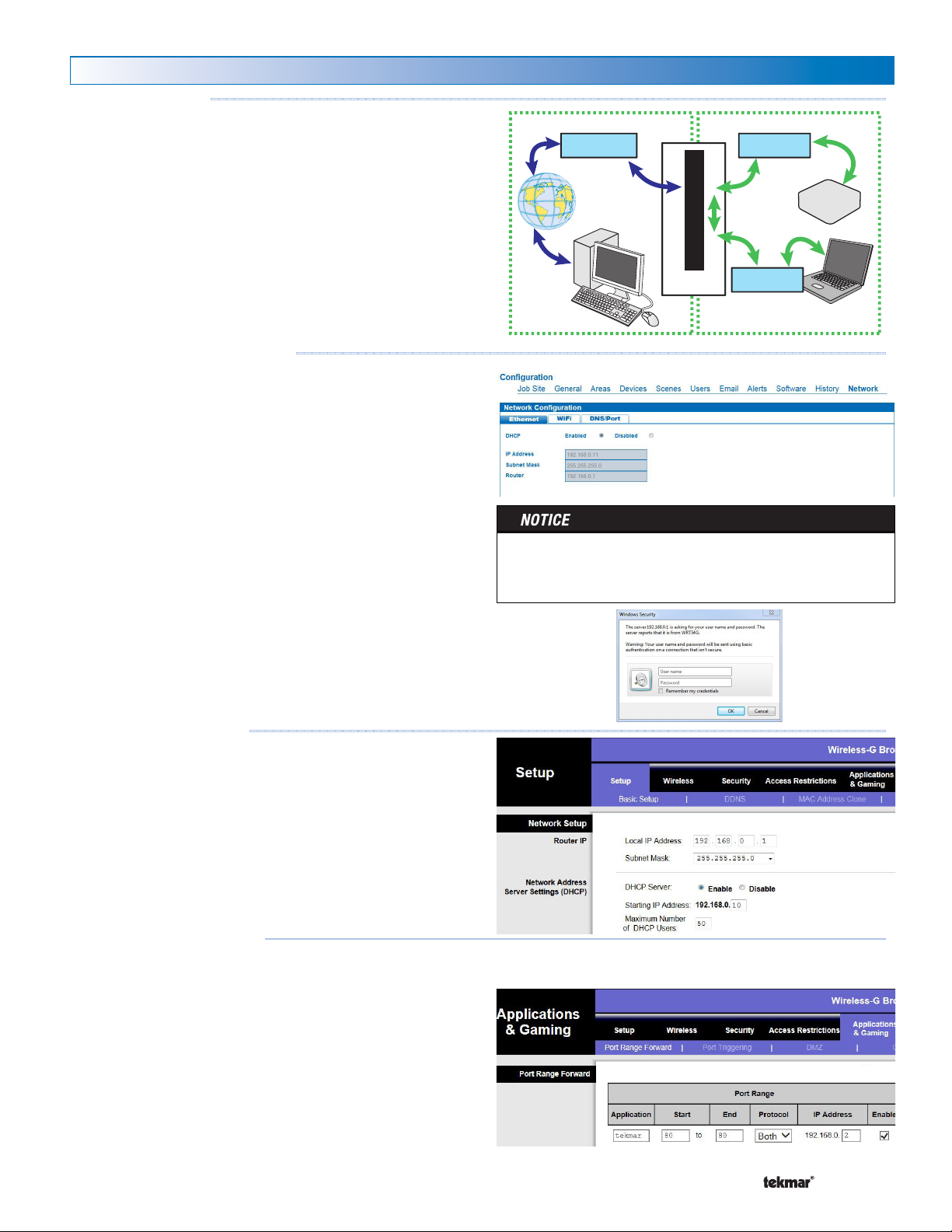
Router Setup
Internal IP
Router
External IP
Remote
Computer
Networked
Computer
Internal IP
Port Forwarding
Gateway
Router Overview
---------------------------------------------------------------------------------------
The 485 must be connected to a router. The router directs
computer network traffic from one computing device to another.
All the devices on the inside of a building form a Local Area
Network (LAN). The router bridges the LAN to the internet and
protects the LAN from unauthorized access from the internet
using a firewall.
Most routers use a DHCP server that automatically assigns
an IP address to a computer. These addresses are dynamic,
which means that particular computer can be given a new IP
address each time it is turned on. Since other computers must
locate the 485 on the network, it is important that the 485 be
given a static LAN IP address.
Login to Router Setup Page
---- ---- ----- ---- ---- -------------------------------------------------------
These directions are provided as a guide to a typical router.
If the router does not follow these setup steps contact
the router manufacturer, router supplier or qualified IT
technician for assistance.
First locate the router setup web page on the LAN. To do this
follow these steps:
Login to the 485 using a computer, tablet or smartphone.
•
Click "Configuration".
•
Click "Network". The 485 will list the router's IP address.
•
Create a new tab on the web browser and enter the router's
•
IP address into the web browser address bar. Two common
router addresses are: 192.168.0.1 or 192.168.1.1
Apple Airport Extreme and Express routers require the
AirPort Utility software program to setup the router. Follow the
instructions: http://www.apple.com/support/airport
Login to the router using the router's username and password.
Consult with the router's manual or check the router for a sticker
to locate this information.
Router DHCP Settings
- - - - -- -- -- -- - - - - - - - - - - - - - - - - - - - ---------------------------------------------------
In the router settings, locate the DHCP settings. Set the DHCP
IP range so that there are eight free IP addresses available. For
example, if the router address is 192.168.0.1, then the DHCP
range should be set to start at 192.168.0.10. This allows eight
static IP addresses to be available (192.168.0.2 to 192.168.0.9).
The router may need to restart when this setting is saved.
Router Port Forwarding
--------------------------------------------------------------------------------
In the router settings, locate the router port forwarding
rules. This feature can have other names depending on the
manufacturer of the router. Other names include port address
translation, network address translation (NAT) or applications
and gaming.
Name the port forwarding rule "tekmar".
•
Open external TCP and UDP port 80.
•
In some cases, internet service providers block port 80. In
•
this case open external port 3000.
Open internal TCP and UDP port 80.
•
Enter the static LAN IP address of the 485 typically 192.168.0.2
•
or 192.16 8.1.2
A Watts Water Technologies Company
13 of 24
© 2015 485_D - 11/15
Page 14
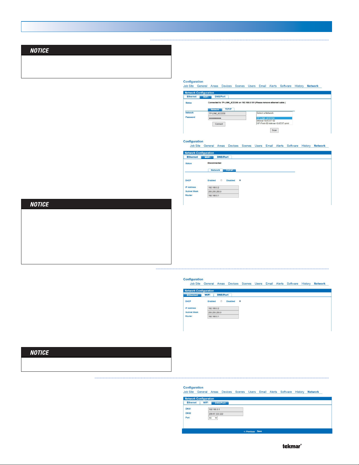
485 Networking
485 Network Settings using WiFi (wireless)
WPA2 encryption is required for WiFi connections. WEP and
•
no encryption options are not supported by the 485.
First select the WiFi network
Click the WiFi tab.
•
Click the Network tab.
•
Scan for available WiFi networks.
•
Select a WiFi network, enter the WiFi password and press
•
the Connect button
Secondly, setup the 485 to have a static IP address
Click the TCP/IP tab.
•
Set the DHCP setting to Disabled.
•
Enter the static IP address. If the router address is 192.168.0.1
•
then the 485 IP can be set to 192.168.0.2.
Enter the Subnet mask. Typically this is set to 255.255.255.0
•
Enter the Router IP address. Check the router's manual for
•
the router's default IP address.
Press the Save button. This requires a reboot of the 485.
•
Click OK.
- - - - - - - - - - - - - - -----------------------------------------------
•
Do not setup Ethernet and WiFi to both have a static IP
address at the same time. This may result in networking
problems.
•
After setup of WiFi, disconnect the Ethernet cable.
Connection of both WiFi and Ethernet may result in networking problems.
Power the router off, then power back on.
•
485 Network Settings using Ethernet (wired)
Setup the 485 to have a static IP address
Click the Ethernet tab.
•
Set the DHCP setting to Disabled.
•
Enter the static IP address. If the router address is 192.168.0.1
•
then the 485 IP can be set to 192.168.0.2.
Enter the Subnet mask. Typically this is set to 255.255.255.0
•
Enter the Router IP address. Check the router's manual for
•
the router's default IP address.
Press the Save button. This requires a reboot of the 485.
•
Click OK.
Power the router off, then power back on.•
Network - DNS and Port
Click the DNS/Port tab.
•
In the DNS1 field enter the IP address of the router.
•
In the DNS2 field enter 208.67.222.222. This directs the 485 to use
•
OpenDNS.com to resolve DNS searches on the Internet.
For new installations, set the port number to 80.
•
•
When replacing a Gateway 483, set the port number to 3000.
•
Click the Save button. This requires a reboot of the 485.
Click OK.
A Watts Water Technologies Company
-- --- -- --- --- ---- ---- ---- --- -- --------------------------------------------------
--- --------------------------------------------------------
14 of 24
© 2015 485_D - 11/15
Page 15
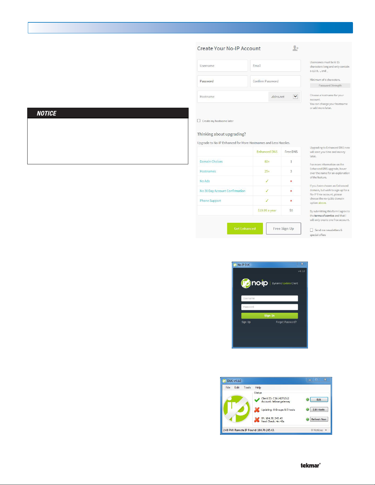
Dynamic DNS
Many Internet Service Providers (ISP) provide a static IP
address with a business account. Residential accounts often
have a dynamic IP address. If the ISP has provided a dynamic
IP address, then a free dynamic DNS service is required.
There are many free dynamic DNS services available. tekmar
suggests to use a free service from NoIP.com.
Go to the web site at http://www.noip.com
•
Create an account by clicking on "Sign Up".
•
When creating a NoIP account an e-mail address is required
to activate the account. The same e-mail account cannot be
used again to create another NoIP account. Therefore, it is
recommended to use the building owner’s e-mail address.
This requires the building owner to read the e-mail and click
on the link to activate the NoIP service.
Fill out a username, email address, password and hostname.
•
The hostname is the web address that is used to access the
gateway over the internet. Click "Free Sign Up".
All No-IP settings are now complete and you can logout of the
No-IP web site.
Download and install the No-IP update client on a computer
or router that shares the same Local Area Network as
the 485.
Download the No-IP Dynamic DNS Update Client software
•
at http://www.no-ip.com/download
Follow the steps to install the No-IP DUC software.
•
When the No-IP DUC window appears, enter the no-ip.com
•
username and password.
From any computer connected to the Internet, start a web
browser and enter the dynamic DNS hostname chosen and
press enter. An example would be:
http://gateway485.ddns.net
The gateway login page will appear. Bookmark this address
in the web browser to allow quick and easy access to the
gateway while on the Internet.
A Watts Water Technologies Company
15 of 24
© 2015 485_D - 11/15
Page 16
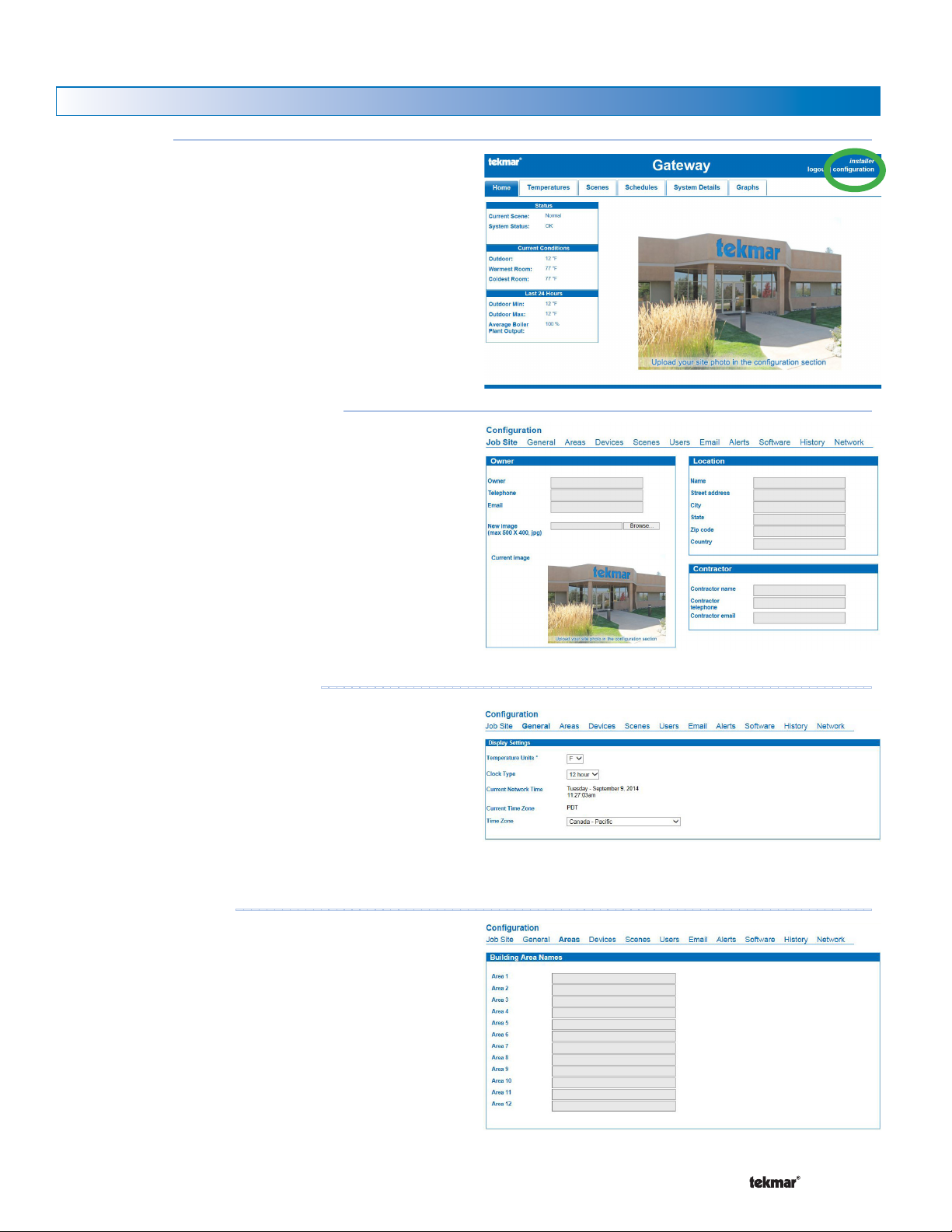
User Interface
Web Page Configuration
Configuration
The 485 requires information to be entered about the heating,
cooling, ventilation and air conditioning (HVAC) system.
To enter this information, click "Configuration".
Configuration - Job Site Information
The Job Site page contains a summary of the building's location,
the building owner or manager and the installing heating
contractor. This allows for support should the HVAC system
need service work. A photo of the building can be uploaded
to personalize the home page for the user.
------------------------------------------------------------------------------------------
- - - - - - - - - - - - - - - - - - - -------------------------------------------------
Configuration - General Settings
The 485 supports different temperature and time formats.
Select the units desired by the building owners:
Temperature units in either Fahrenheit or Celsius
•
12 or 24 hour time format
•
Time zone
•
The 485 synchronizes its time clock from the internet. If the
485 is connected to a LAN but is unable to reach the internet,
the 485 will continue to use the time set at the factory.
Configuration - Areas
An area is a group of rooms that are near to one another. A
floor or wing is an example of an area. Enter up to 12 areas
that thermostats can belong to.
----------------------------------------------------------------------------------
---------- ---------- ---------------------------------------------------
A Watts Water Technologies Company
16 of 24
© 2015 485_D - 11/15
Page 17
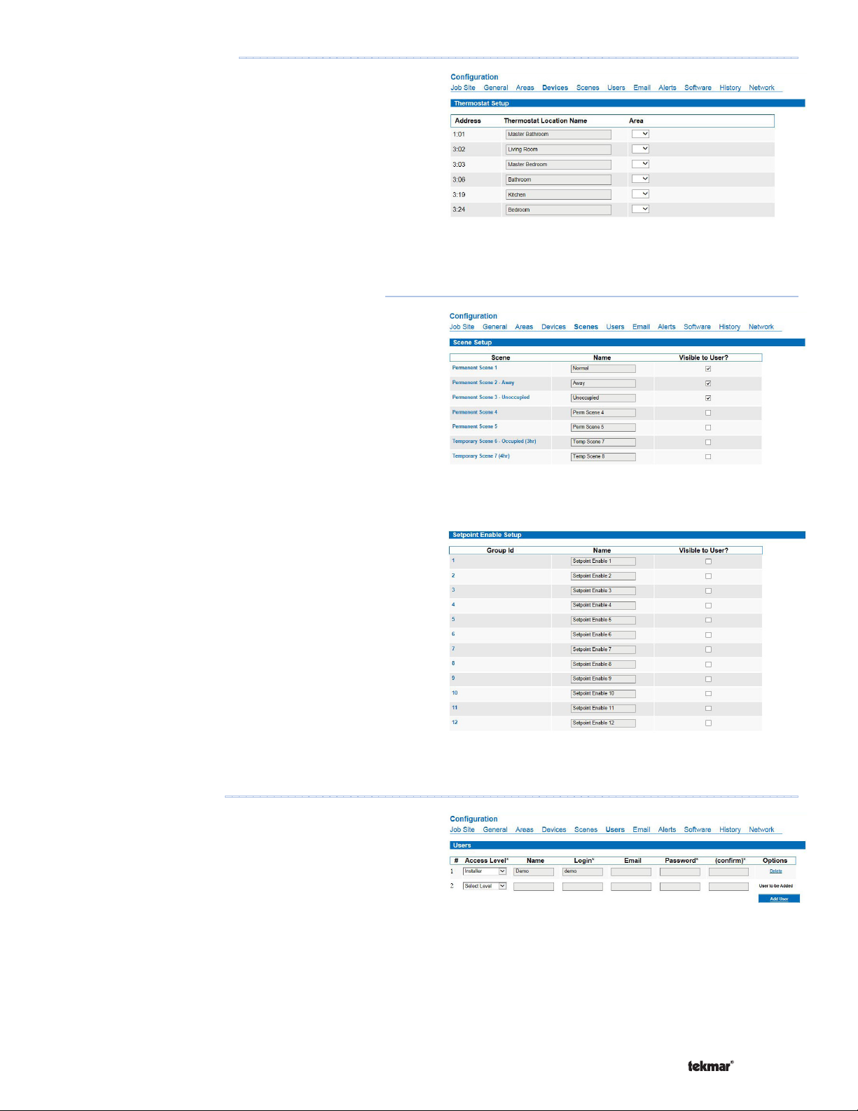
Configuration - Devices
Each thermostat can be given a room name. Each thermostat
is listed using its tekmarNet® address. Locate the address on
each thermostat display and enter the room name. Assign an
area name to the thermostat using the drop-down menu.
--------------------------------------------------------------------------------
Configuration - Scenes and Setpoint Enable
Scenes are building wide overrides that allow the user to change
the building temperature from comfort to economy operation.
The tekmarNet® system can operate in one of eight scenes.
Each scene can be given a custom name and each scene can
be selected whether or not it is visible to the user.
The Setpoint Enable is used to activate or disable a setpoint
or snow melt control. This can be used to remotely activate
snow melt systems, hot tubs, and patio heaters.
-----------------------------------------------------------
Configuration - Users
Click on New User to create a login for each person that will
have access to the 485.
For each login account, select the access level that the person
has to the 485. The installer access level allows access to
all of the 485 web pages. The user access level only allows
access to the Home, Temperatures, and Scene web pages.
This access is recommended for the average home owner.
Provide the account with a name, login name, email address
and password. Click ‘Add User’ to create the account.
The login and password are case sensitive. The login must
be at least 3 characters and the password must be at least
4 characters.
A Watts Water Technologies Company
----------------------------------------------------------------------------------
17 of 24
© 2015 485_D - 11/15
Page 18
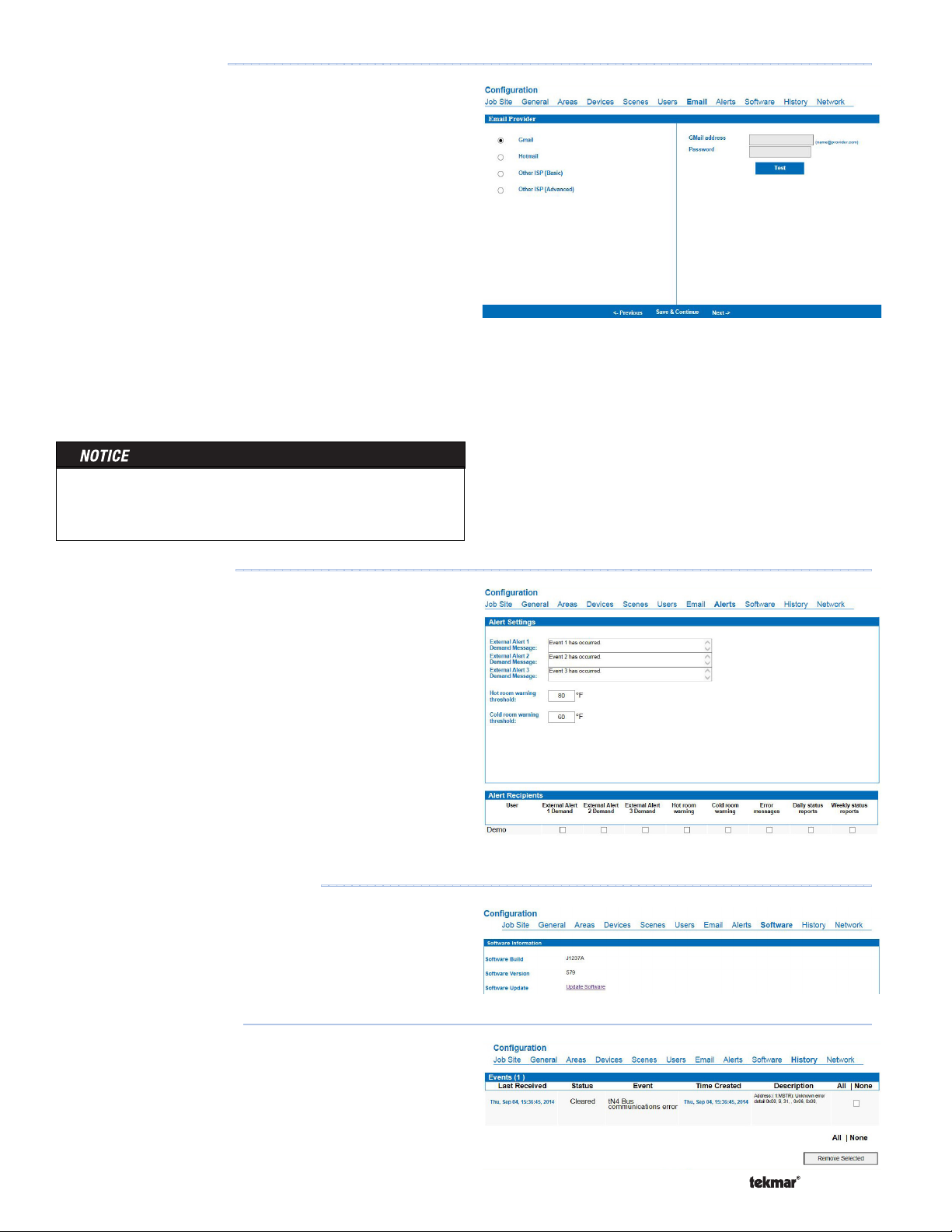
Configuration - Email
In order to send email to user accounts, the 485 must connect
to a mail server. Gmail & Hotmail accounts require a user
name and password. Some Internet service providers (ISP’s)
only require the SMTP server address, others will require
additional settings.
Contact your ISP to determine the following advanced email
settings:
•
SMTP Server Address
•
SMTP Server Port
•
Email account user name
•
Email account password
•
HELO domain
•
Authentication mode Plain, Login or CRAM MD5
•
If TLS / SSL is used
Once the email server settings have been entered, click Save
& Continue. Clicking the test button sends a test message to
the email account. Please note the test button does not save
the password or email settings.
Sending emails requires that the DNS settings be entered on
the configuration - network page. Emails will not send if the
DNS field is left empty or are incorrect.
- - - - - - -- - -- - - -- - -- - -- - -- - - -- - -- - -- -------------------------------------------------
Configuration - Alerts
The Alerts page provides a form for a short message to be
included in a notification email whenever an Alert Input is
activated.
Room hot and cold warning thresholds can be set on the Alerts
page. Should the temperature exceed the hot room setting or
fall below the cold room setting, an email can be sent.
The following items can be selected to notify individual users
when they occur:
Alert inputs - sent immediately
•
Hot room warning - sent each hour on the hour
•
Cold room warning - sent each hour on the hour
•
Error messages - sent each hour on the hour
•
Daily status reports - sent each day at midnight
•
Weekly status reports - sent each Sunday at midnight
•
Configuration - Software Update
The 485 software can be updated. Click the Update Software
button to check if new software is available.
----------------------------------------------------------------------------------
-----------------------------------------------------------------------
Configuration - History
All error and warning messages are stored in a list and are
timestamped. Individual error or warning messages can be
cleared by the user.
A Watts Water Technologies Company
- -- - - - -- - - -- - - -- - - - -- - - -- - - - -- - - -------------------------------------------------
18 of 24
© 2015 485_D - 11/15
Page 19
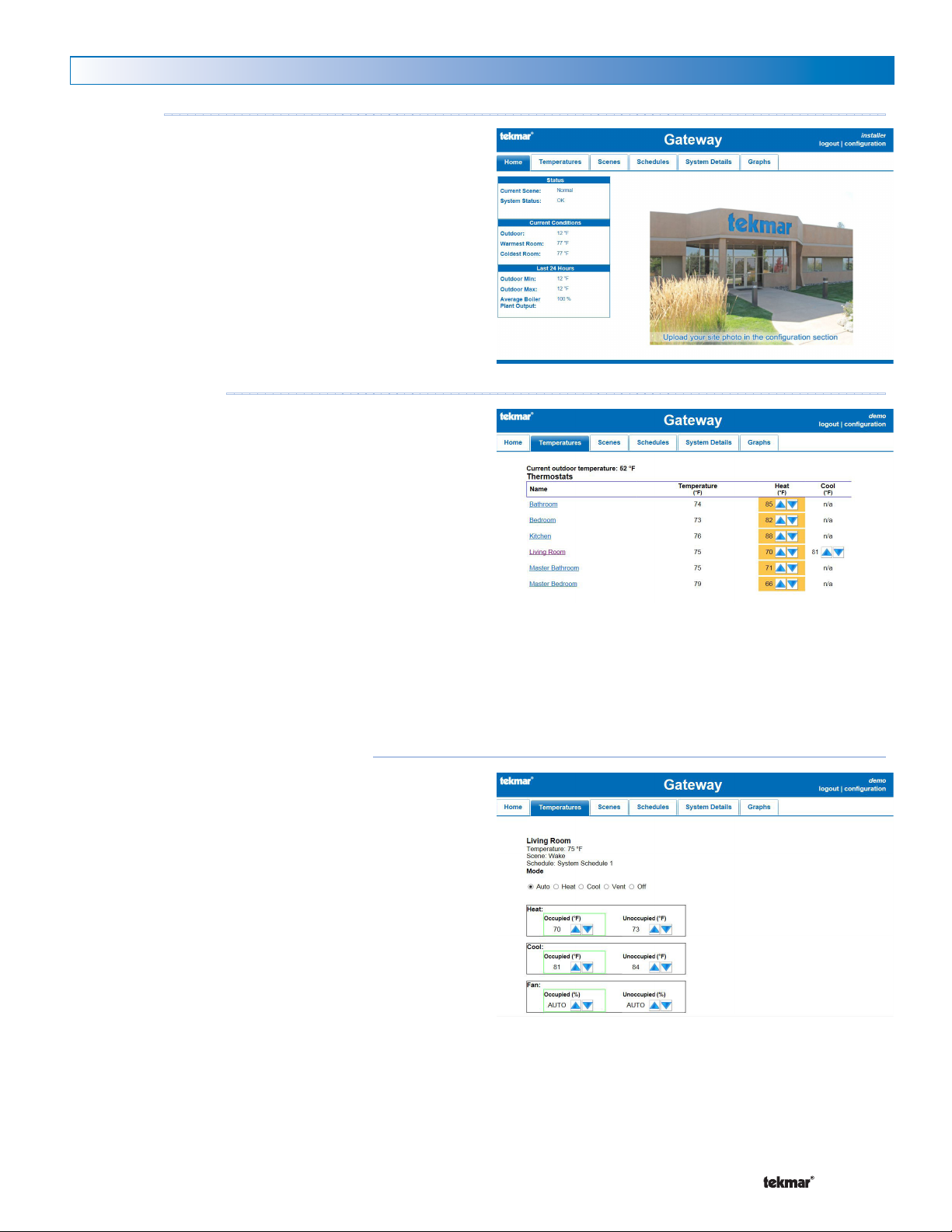
Using the Web Pages
Home Page
The Home page shows a photograph of the building and a
summary of the heating system including:
Scene
•
Error messages present
•
Outdoor air temperature
•
Warmest and coldest room temperatures
•
Outdoor highs and lows
•
Boiler plant output averaged over the last 24 hours
•
Temperatures Page
The Temperatures page list all thermostat's temperature
measurement and the current heating and cooling setting. In
addition, setpoint controls and snow melt controls are also listed.
Click the up or down buttons to adjust the temperature.
The heat setting automatically increases the cooling setting if
adjusted within 3°F (1.5°C) of the cooling setting. Likewise, the
cooling setting automatically decreases the heating setting if
adjusted within 3°F (1.5°C) of the heating setting. This prevents
cycling between heating and cooling on the thermostat. An
orange box indicates that the thermostat is heating and a blue
box indicates that the thermostat is cooling.
Loading...
The Temperatures page shows "Loading..." instead of the
thermostat temperature while the 485 is downloading the
thermostat settings. This only occurs when the 485 is powered
on for the first time and can take up to 5 to 10 minutes per
thermostat depending on the tekmarNet® network activity.
- - - - - - - - - - - - - - - - - - - - - - - - - - - - - - - - - - - - - - - - - - ---------------------------------------------------
- - - - - - - - - - - - - - - - - - - - - - - - - - - - - - - - - - ---------------------------------------------------
Temperatures - Individual Thermostat
Click on the thermostat name to access the individual thermostat
or setpoint control settings.
The current temperature, relative humidity, scene and schedule
status are shown.
The mode can be set to Auto, Heat, Cool, or Off. The options
available are determined by the thermostat model.
The Heat setpoints are available when mode is set to Heat
or Auto.
The Cool setpoints are available when mode is set to Cool
or Auto.
The Fan settings are available when a fan is available on the
thermostat.
The Heat, Cool, and Fan may have multiple settings depending
if a setback schedule is used on the thermostat. If no schedule
is used then only the Occupied setting is available. If a two
event schedule is used, then the Occupied and Unoccupied
settings are available. If a four event schedule is used, then
the Wake, Unoccupied, Occupied, and Sleep settings are
available.
A green box around a setting indicates the current schedule
event of the device.
A Watts Water Technologies Company
- - - - - - - - - - - - - - - ---------------------------------------------------
19 of 24
© 2015 485_D - 11/15
Page 20
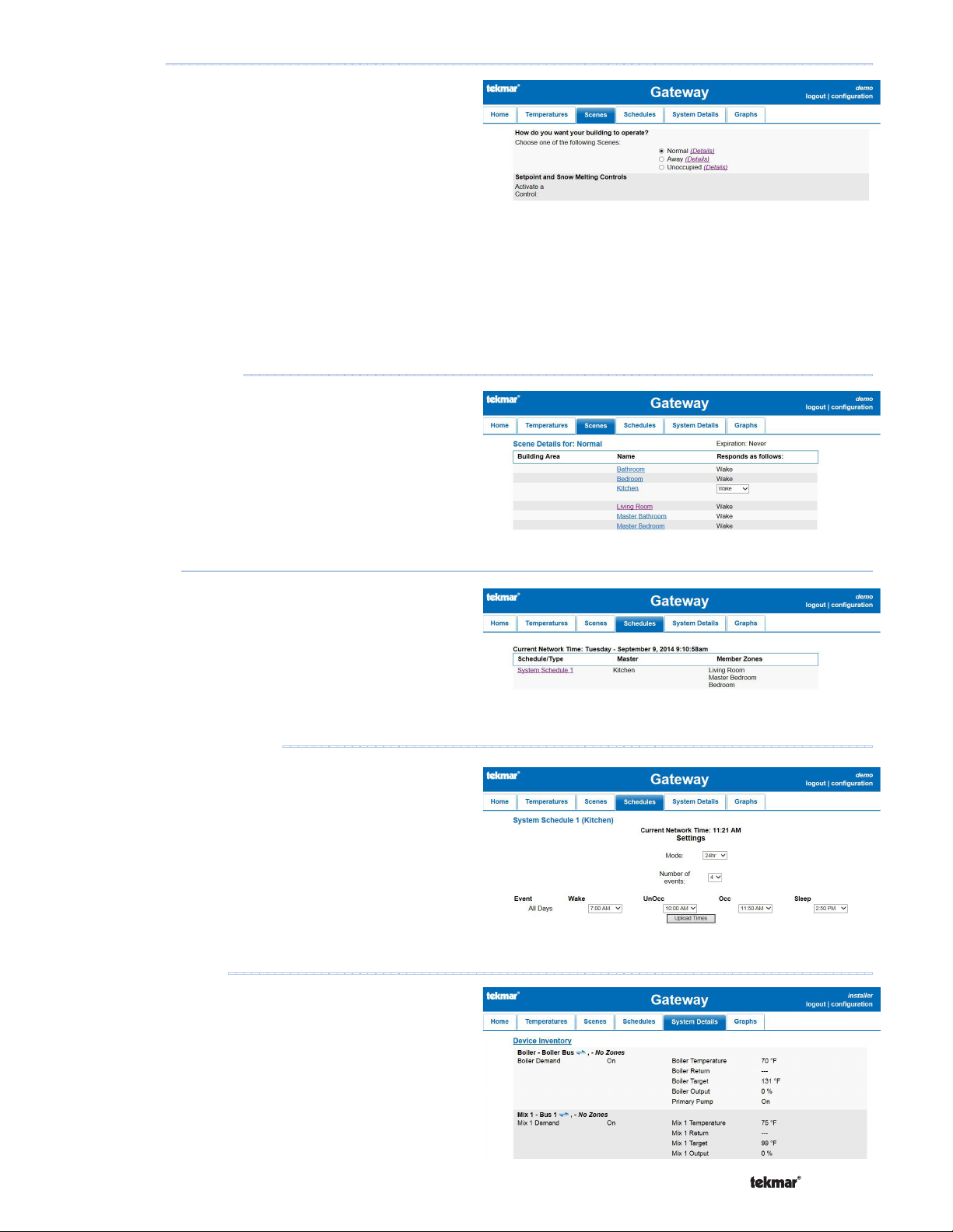
Scenes Page
The Scenes page allows the user to select the scene for the
building. For example, the scene could be set to Normal while
the building is occupied, and then set to Away while the building
occupants are away on vacation.
The setpoint enable allows hot tubs, patio heating and snow
melt systems to be remotely activated. Setpoint controls that
are using the setpoint device enable feature can be activated
or placed in standby operation using the scenes page. Click
on the Active button to have the setpoint control operate at
the Occupied temperature setting. Click the Standby button to
have the setpoint control operate at the standby setting. The
standby temperature setting is set by the application mode
configured on the setpoint control.
---- ---- ---- ---- ---- ---- ---- ---- ---- ---- ---------------------------------------------------
Scenes - Scene Details
The Scenes Details lists the response of each thermostat in
a particular scene. Adjustability of each scene is dependant
on the particular thermostat model and how the thermostat is
configured. Consult the thermostat installation and operation
manual for detailed information.
Schedule Page
The Schedule page lists the schedules on the tekmarNet®
system, the location of the schedule master thermostat, and the
thermostats that are members of this schedule. Thermostats
that have their own programmable schedule which are not
shared are listed as "zone".
-- ----- ----- ----- ----- ----- ----- ----- ----------------------------------------------------
Schedule - Schedule Details
On the Schedules pages, click the schedule name to access
the schedule settings.
For each schedule event time, enter the time for the event to
start, rounded to the nearest ten minutes.
Click on the Upload Times button to send the settings to the
thermostat.
- - - - - - - - - - - - - - - - - - - - - - - - - - - - - - - - -------------------------------------------------
- - - - - - - - - - - - - - - - - - - - - - - - - - - -------------------------------------------------
System Details Page
The System Details page provides information on the hot
water heating system. Details such as the presence of a heat
demand signal, boiler and mix target temperatures, actual
boiler and mix temperatures and boiler and mix percent output
levels are shown in detail.
A Watts Water Technologies Company
-----------------------------------------------------------------------------------
20 of 24
© 2015 485_D - 11/15
Page 21
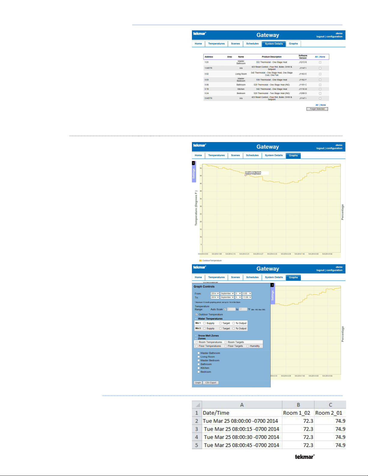
System Details - Device Inventory
The Device Inventory page lists the tekmarNet® address of each
device in the tekmarNet® system, the area name, the thermostat
or setpoint control name, the product model number, product
name and description, and the software version.
In some cases, a device may have been connected to a
tekmarNet® bus and then removed. Click the Forget button
to remove the device from the database. If the device is still
on the tekmarNet® bus, the gateway will automatically detect
and add the device to the database.
If a device shows "Loading..." on the Temperatures page for
several hours, then the device may no longer be installed on
the system or the database may have been corrupted. Select
the device on the device inventory page and click the Forget
Selected button to remove it from the database.
- -- - - - -- - - - -- - - - -- - ---------------------------------------------------
Graphs Page
The 485 captures and logs data at a 15 second interval and
stores data for up to 13 months. The data can then be graphed
or exported to compare the previous year's data with the current
year's data. The following data is available:
Outdoor temperature
•
Room temperature
•
Heating and cooling temperature setpoints
•
Relative humidity
•
Relative humidity setpoints
•
Floor temperature
•
Floor setpoint
•
Boiler temperature
•
Boiler target
•
Boiler percent output (firing rate)
•
Boiler demand
•
Mixing temperature
•
Mixing target
•
Mixing demand
•
Heat pump tank temperature
•
Snow melt operational status
•
Snow melt sensor wet or dry status
•
-------------------------------------------------------------------------------------------
Graphs - Exporting Data
Instead of graphing data, the 485 supports the export of data
to a Comma Separated Value (CSV) document format that
can be opened by most spreadsheet programs. The maximum
number of data points that can be exported is 1024.
A Watts Water Technologies Company
- - - - - - - - - - - - - - - - - - - - - - - - - - - - - ---------------------------------------------------
21 of 24
© 2015 485_D - 11/15
Page 22
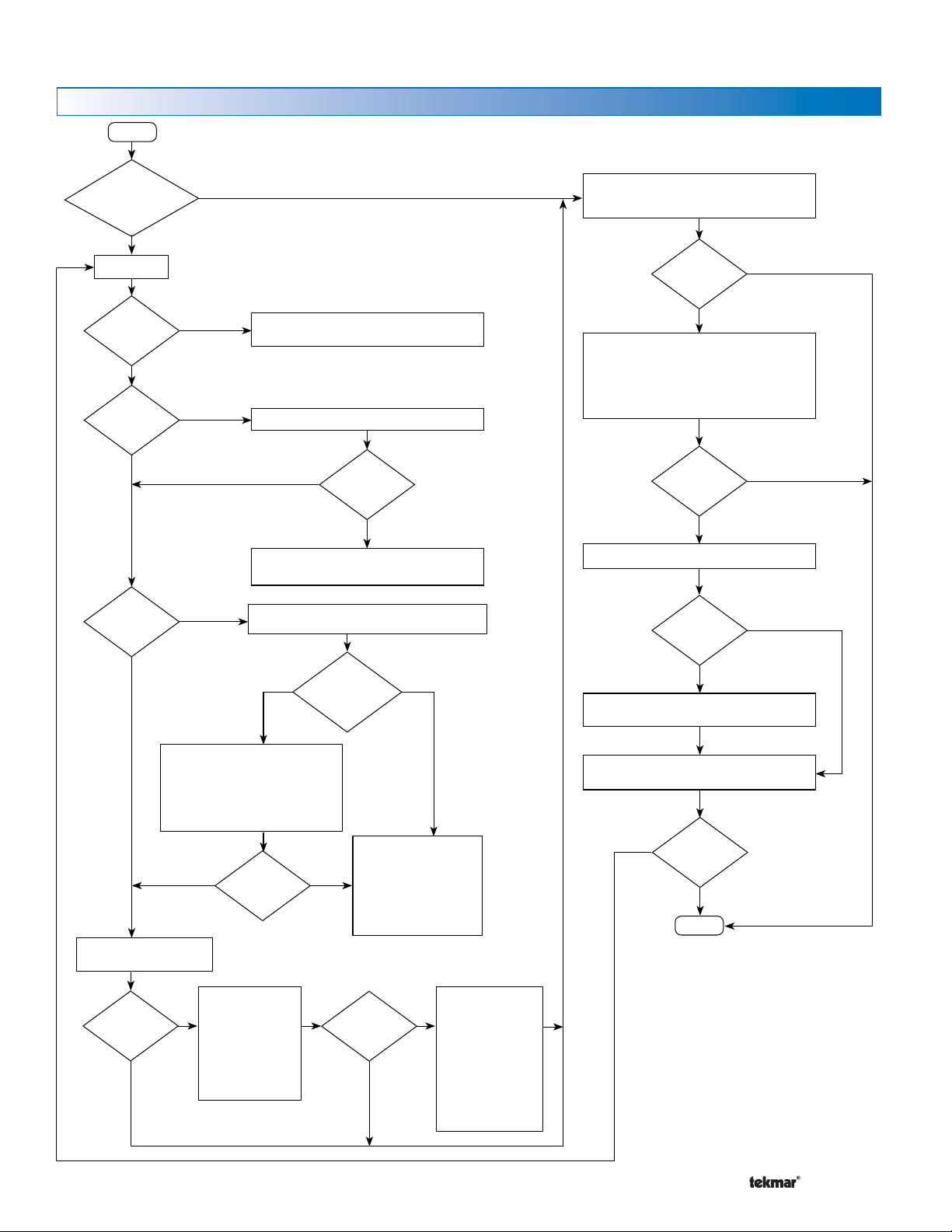
Troubleshooting
Trouble Reaching Login Page
Start
Accessing
the 485 from the internet
or the building
LAN?
Building LAN
Go to the 485
Is the Power
LED on?
Yes
Is the
Gateway Ready
LED on solid?
Yes
Is the WiFi /
Ethernet
LED
on?
Yes
No
No
No
Internet
Check if the wall plug power supply is plugged into the
485 and to the wall power outlet.
The 485 takes up to 5 minutes to start.
After 5 minutes,
Yes
is Status OK
LED on?
No
Unplug wall plug power supply, wait 10 seconds, then
reconnect wall plug power supply.
485 is not connected to Ethernet (wired) or WiFi (wireless).
Wired
Is the 485 using
wired or wireless
networking?
Wireless
Using a computer or phone connected to the Internet,
open a web browser and enter the 485’s static IP
address or the no-ip.com hostname.
Does
the login
web page
appear?
Check the 485 static IP address on the LAN. Then
check the router port forwarding rule.
Forward to 485 IP address
•
External port 80
•
Internal port 80
•
Both TCP and UDP protocols
•
Does
the login
web page
appear?
Go to No-IP.com and login.
Is the
NO-IP.com
account
active?
Create a new No-IP.com account.
Yes
No
Yes
No
Yes
No
Check that the Ethernet cable is
connected to the 485 and to the router.
The router has an indicator LED to show
that the Ethernet cable is connected.
Wait for 30 seconds if cable reconnected.
Yes
Is the WiFi /
Ethernet
on?
Open a web browser and enter
http://tekmargateway.local
Power off the 485 and
Does the login
web page
appear?
Yes
power back on.
No
Power off the router
and power back on.
Wait for Gateway
Ready and WiFi /
Ethernet LED to turn
back on.
A Watts Water Technologies Company
LED
No
Press and hold the restart
button for 5 seconds. This
restores the 485 to the
factory default using DHCP
(automatic) addressing.
Wait for 5 minutes for 485
to restart.
Does the login
web page
appear?
No
Yes
Login to the router's
configuration page.
The router DHCP
client list will show
tekmargateway as a
device on the network.
Click on the link or
enter the tekmar
gateway's IP address
into the web browser
address bar.
22 of 24
Open the No-IP dynamic update client (DUC) on the
computer or router and check its settings.
Does
the login
No
web page
appear?
Yes
End
© 2015 485_D - 11/15
Page 23
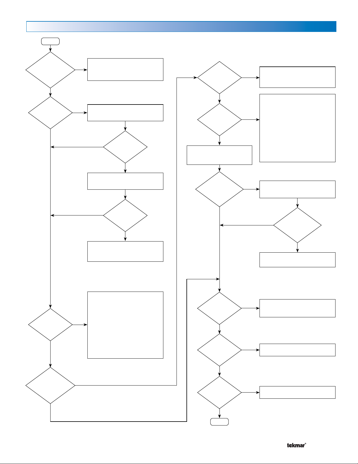
Trouble Viewing Web Pages
Start
Red
Banner with:
“Communication
error on bus…”
error on web
page?
No
Thermostat page
showing “loading”
No
A tN4 bus is not communicating with the 485.
Yes
All tN4 buses on a control must be wired to
the 485. This includes tN4 buses with no
thermostats connected.
Yes
The 485 must gather data from each
thermostat. Allow 5 minutes per thermostat
times the number of thermostat in the system.
Thermostat still
No
shows “loading”
after several
hours?
Yes
Is this a new
installation?
No
Does the error
occur while on the
Graphing page?
No
Go to System Details page > Device
Inventory > click All, then click
“Forget Selected”.
Yes
Yes
The 485 must gather data from each
thermostat. Allow 5 minutes per thermostat
times the number of thermostats in the system.
Clear the computer’s web browser cache.
Internet Explorer:
Too ls > Internet Options > General > Browsing
history > Delete
Firefox:
Too ls > Options >Privacy > History > Clear
your recent history
Chrome:
Control Chrome button > History, select Clear
browsing data
Tem peratures page
missing Up and
Down arrows?
No
Go to System Details > Device Inventory,
check mark the problem thermostat and click
Too ls>Options>Security>Set to Medium - High
Yes
Too ls>Options>Content>Enable Javascript
“Forget Selected”.
Thermostat still
No
shows “loading”
after several
hours?
Unplug wall plug power supply, wait 10
seconds, then reconnect wall plug power
Javascript has been disabled on the
customers web browser. Recommend
Settings > Advanced Settings > Privacy
Content Settings > Allow all sites to run
supply.
enabling Javascript.
Internet Explorer:
(not High)
Firefox:
Chrome:
JavaScript
Yes
“Something
went wrong, call
tekmar customer
service” error
continues?
No
Unable to view
Gateway 485 web
pages on
iPhone?
No
Unable to view
Graphing page?
Yes
Yes
Yes
Unplug wall plug power supply, wait 10
seconds, then reconnect wall plug power
No
Reset factory defaults by pressing and holding
the restart button for 10 seconds.
iPhone needs to support “Cookies”
On iphone, Settings > Safari > Accept
Cookies, choose “From Visited”
Graphing requires a web browser that
supply.
“Something
went wrong, call
tekmar customer
service” error
continues?
supports HTML5
Yes
“Something went
wrong, call tekmar
customer service”
error message?
No
Yes
A Watts Water Technologies Company
23 of 24
No
Is there
something else
on the web page
not working?
End
Yes
Contact tekmar customer service
© 2015 485_D - 11/15
Page 24
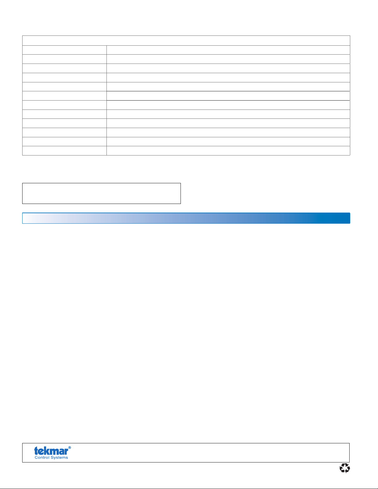
Technical Data
tekmarNet® Internet Gateway 485 WiFi / Ethernet
Literature 485_C, 485_D, 485_Q, 485_B
Control Microprocessor control. This is not a safety (limit) control
Packaged weight 2.9 lb. (1300 g)
Dimensions 6-5/8" H x 7-9/16" W x 2-13/16" D (170 x 193 x 72 mm)
Enclosure Blue PVC plastic, NEMA type 1
Approvals Class B: ICES & FCC Part 15
Ambient conditions Indoor use only, 32 to 122°F (0 to 50°C), RH maximum 90%, non-condensing
Power supply 5 V (dc) regulated, 1 A, Class 2, FCC certified
Alert inputs Short, 0 - 32 V (ac)
Ethernet 10/10 0 BASE-T
WiFi 802.11n, 2.4 GHz, WPA2 encryption
Warranty Limited 3 Year
WARNING: This product contains chemicals known to the State of California to
cause cancer and birth defects or other reproductive harm. For more information:
www.watts.com/prop65
L i mited Warranty and Product Return Procedure
Limited Warranty The liability of tekmar under this warranty is lim-
ited. The Purchaser, by taking receipt of any tekmar product (“ Product”), acknowledges the terms of the Limited Warranty in effect at
the time of such Product sale and acknowledges that it has read
and understands same.
The tekmar Limited Warranty to the Purchaser on the Products sold
hereunder is a manufacturer’s pass-through warranty which the
Purchaser is authorized to pass through to its customers. Under
the Limited Warranty, each tekmar Product is warranted against
defects in workmanship and materials if the Product is installed and
used in compliance with tekmar’s instructions, ordinary wear and
tear excepted. The pass-through warranty period is for a period of
twenty-four (24) months from the production date if the Product is
not installed during that period, or twelve (12) months from the documented date of installation if installed within twenty-four (24) months
from the production date.
The liability of tekmar under the Limited Warranty shall be limited to, at
tekmar’s sole discretion: the cost of parts and labor provided by tekmar
to repair defects in materials and/or workmanship of the defective product; or to the exchange of the defective product for a warranty replacement product; or to the granting of credit limited to the original cost of the
defective product, and such repair, exchange or credit shall be the sole
remedy available from tekmar, and, without limiting the foregoing in any
way, tekmar is not responsible, in contract, tort or strict product liability, for any other losses, costs, expenses, inconveniences, or damages,
whether direct, indirect, special, secondary, incidental or consequential,
arising from ownership or use of the product, or from defects in workmanship or materials, including any liability for fundamental breach of
contract.
The pass-through Limited Warranty applies only to those defective Products returned to tekmar during the warranty period. This Limited Warranty does not cover the cost of the parts or labor to remove or transport
the defective Product, or to reinstall the repaired or replacement Product,
all such costs and expenses being su bject to Purchaser’s agreement and
warranty with its customers.
Any re presentations or warranties ab out th e Products made by Pu rchaser
to its customers which are different from or in excess of the tekmar Limited Warranty are the Purchaser’s sole responsibility and obligation. Purchaser shall indemnify and hold tekmar harmless from and against any
and all claims, liabilities and damages of any kind or nature which arise
out of or are related to any such representations or warranties by Purchaser to its customers.
The pass-through Limited Warranty does not apply if the returned Product has been damaged by negligence by persons other than tekmar,
accident, fire, Act of God, abuse or misuse; or has been damaged by
modifications, alterations or attachments made subsequent to purchase
which have not been authorized by tekmar; or if the Product was not
installed in compliance with tekmar’s instructions and/or the local codes
and ordinances; or if due to defective installation of the Product; or if the
Product was not used in compliance with tekmar’s instructions.
THIS WARRANTY IS IN LIEU OF ALL OTHER WARRANTIES, EXPRESS
OR IMPLIED, WHICH THE GOVERNING LAW ALLOWS PARTIES TO
CONTRACTUALLY EXCLUDE, INCLUDING, WITHOUT LIMITATION,
IMPLIED WARRANTIES OF MERCHANTABILITY AND FITNESS FOR
A PARTICULAR PURPOSE, DURABILITY OR DESCRIPTION OF THE
PRODUCT, ITS NON-INFRINGEMENT OF ANY RELEVANT PATENTS
OR TRADEMARKS, AND ITS COMPLIANCE WITH OR NON-VIOLATION OF ANY APPLICABLE ENVIRONMENTA L , HEALTH OR SAFETY
LEGISLATION; THE TERM OF ANY OTHER WARRANTY NOT HEREBY
CONTRACTUALLY EXCLUDED IS LIMITED SUCH THAT IT SHALL NOT
EXTEND BEYO ND TWENTY-FOUR (24) M ONTHS FROM TH E PRODUCTION DAT E, TO THE EXTENT THAT SUCH LIMITAT ION IS ALLOWED BY
THE GOVERNING LAW.
Product Warranty Return Procedure All Products that are believed to
have defects in workmanship or materials must be returned, together
with a written description of the defect, to the tekmar Representative
assigned to the territory in which such Product is located. If tekmar
receives an inquiry from someone other than a tekmar Representative,
including an inquiry from Purchaser (if not a tekmar Representative) or
Purchaser’s customers, regarding a potential warranty claim, tekmar’s
sole obligation shall be to pr ovide the address and other contact information regarding the appropriate Representative.
tekmar Control Systems Ltd., A Watts Water Technologies Company.
Vernon, B.C. Canada V1B 3K4, 250-545-7749, Fax. 250-984-0815 Web Site: tekmarControls.com
Produ
ct design, software and literature are Copyright ©2015 by
tekmar Control Systems Ltd.,
A Watts Water Technologies Company
24 of 24
Head Offi c e: 5100 Silver Star Road,
All s
pecifications are subject to change without notice.
Printed in Canada. 485_D - 11/15.
 Loading...