

Page 1
- Data Brochure
D 039
Remote Start / Stop Module 039
The tekmar Remote Start / Stop Module 039 provides the user with
the ability to start and stop a snow melting system. As well, the 039
gives the user the ability to adjust the running time of their snow
melting system. An indicator light on the face of the 039 provides
a visual indication as to the current operation of the snow melting
system. The 039 is designed to work with specific tekmar snow
79
8
melting controls. Read the Data Brochure of the applicable control
to determine if the 039 is compatible with the intended control.
The 039 cannot be used on tekmar controls that do not support a
tekmar Net™ (tN2) device.
05/07
Installation
STEP ONE
Place a screwdriver or similar object into the small slot located in the top of the 039. Push
the screwdriver against the plastic tab and pull the top of the front cover so that it pivots
around the bottom edge of the 039.
REMOVING THE FRONT COVER
To Control
#6 1” screws
STEP TWO
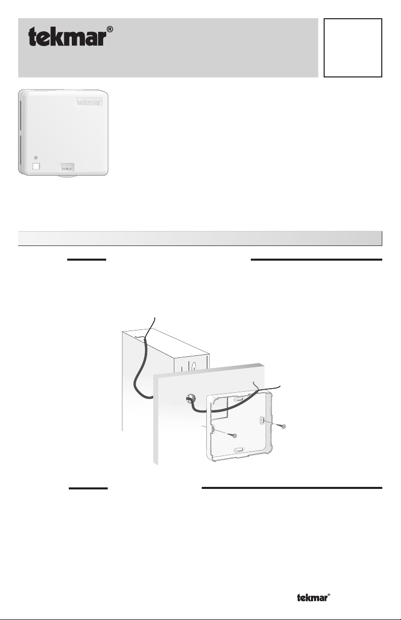
The base of the 039 should be securely installed in the desired location. Mount the 039
directly to the desired location using two #6-1” screws. The screws are inserted through the
mounting holes and must be securely fastened to the desired location. If possible, at least
one of the screws should enter a wall stud or similar surface. If the 039 is to be mounted
to a 2” x 4” electrical box, order an Adaptor Plate 007. This plate will mount to the electrical
box and the 039 will then mount to the plate.
1 of 4 © 2007 D 039 - 05/07
MOUNTING THE 039
Page 2

STEP THREE
•
•
•
WIRING THE 039
Run 18 AWG twisted pair or similar wire between the 039 and the control. Insert the wires
through the hole provided in the back of the 039 enclosure and connect them to the Com
and tekmar Net™(tN2) terminals. Do not run the wires parallel to telephone or power lines
as this may interfere with the operation of the 039. If the 039 wires are located in an area
with strong sources of electromagnetic noise, shielded cable should be used or the wires
can be run in a grounded metal conduit.
NOTE: Do not apply power to the 039. The 039 is to be wired directly
to the control. The connection between the control and the 039 is
polarity sensitive. The Com terminal of the 039 must be connected
tN2
2
1
Com
to the appropriate terminal of the control. If the wires are reversed,
the 039 will not function and the control will display a short circuit
error for the tekmar Net™ (tN2) device.
STEP FOUR
INSTALLING THE FRONT COVER
Align the hinges on the bottom of the front cover with the bottom of the 039 mounting base.
Pivot the front cover around the bottom hinges and push the top against the mounting base
until it snaps firmly in place.
Settings
LIMITING THE TIME RANGE
The time range on the 039 can be limited in order to
avoid extreme time settings or any tampering with the
setting.
• Turn the dial until the desired time is at the bottom
of the 039.
• Remove the front cover by following Step One of
the Installation procedure.
Lift and pull the scale off the dial. Be careful not
to turn the dial while removing the scale. With the
scale off, a series of small holes will be visible
around the dial. Behind the dial there is a post
which can be used to limit the rotation of the dial.
Two aluminum limit pins are provided in the dial.
Holding Clip
SETTING A MINIMUM TIME LIMIT
Remove one of the limit pins and re-insert it into the hole that is slightly to the left of the post
at the bottom of the dial. With the pin in place the dial should only rotate clockwise from its
current position as the counter-clockwise rotation is now restricted by the pin.
The 039 can be used to set the desired running time of the snow melting system. Turn the
039’s dial until the desired running time is displayed in the window.
NOTE: If an infinite (NO LIMIT) run time is selected, the snow melting system runs
continuously until WWSD or CWCO occurs, or someone presses the start / stop button
on the 039.
© 2007 D 039 - 05/07 2 of 4
Page 3

SETTING A MAXIMUM TIME LIMIT
•
•
•
•
Insert one of the pins into the hole that is slightly to the right of the post.
SETTING A FIXED TIME
Insert one of the pins into the hole in the bottom of the dial such that the pin enters the post
behind the dial. With the pin in place the dial should be fixed in position. Replace the scale
by sliding it onto the dial until the rectangular hole slips into the holding clip. Replace the
front cover by following Step Four of the Installation procedure.
Operation
STARTING THE SNOW MELTING SYSTEM
To start the snow melting system, press and release the button on the face of the 039.
INDICATOR LIGHT
An indicator light is located on the face of the 039 to provide a visual indication of the current
operating status of the snow melting system.
• Flashing Green Indicator indicates that the snow melting system is currently coming
up to its desired snow melting temperature.
• Solid Green Indicator indicates that the snow melting system is currently operating
at its desired snow melting temperature.
• Solid Red Indicator When the 039 button is pushed to stop snow melting operation,
a solid red light is displayed on the face of the 039 for five seconds. If the snow melting
system is stopped while there is still an external demand for snow melting, the 039
displays a solid red indicator light until the external demand is removed. Refer to the
Data Brochure of the snow melting control for a description of an external demand.
• Flashing Red Indicator If the indicator on the face of the 039 is a flashing red light,
this indicates that the snow melting control is currently displaying an error message.
Refer to the snow melting control and the control’s Data Brochure to determine the
error. Locate and repair the problem as described in the Data Brochure for the snow
melting control.
STOPPING THE SNOW MELTING SYSTEM
To stop the snow melting system when it is running, press and release the button on the
face of the 039.
3 of 4 © 2007 D 039 - 05/07
Page 4

Technical Data
REMOTE START / STOP MODULE 039
Literature D 039
Packaged weight 0.22 lb. (100 g), Enclosure G, white PVC plastic
Dimensions 2-7/8” H x 2-7/8” W x 13/16” D (73 x 73 x 21 mm)
Approvals CSA NRTL/C, meets DOC & FCC regulations for EMI/RFI.
Ambient conditions Indoor use only, 32 to 122°F (0 to 50°C), < 90% RH non-condensing.
Power Supply tekmar control; tekmarNet™2 (tN2)
Limited Warranty and Product Return Procedure
Limited Warranty The liability of tekmar under this warranty is limited. The Purchaser, by taking receipt of
any tekmar product (“Product”), acknowledges the terms of the Limited Warranty in effect at the time of
such Product sale and acknowledges that it has read and understands same.
The tekmar Limited Warranty to the Purchaser on the Products sold hereunder is a manufacturer’s passthrough warranty which the Purchaser is authorized to pass through to its customers. Under the Limited
Warranty, each tekmar Product is warranted against defects in workmanship and materials if the Product
is installed and used in compliance with tekmar’s instructions, ordinary wear and tear excepted. The passthrough warranty period is for a period of twenty-four (24) months from the production date if the Product is
not installed during that period, or twelve (12) months from the documented date of installation if installed
within twenty-four (24) months from the production date.
The liability of tekmar under the Limited Warranty shall be limited to, at tekmar’s sole discretion: the cost of parts
and labor provided by tekmar to repair defects in materials and / or workmanship of the defective product; or to
the exchange of the defective product for a warranty replacement product; or to the granting of credit limited to the
original cost of the defective product, and such repair, exchange or credit shall be the sole remedy available from
tekmar, and, without limiting the foregoing in any way, tekmar is not responsible, in contract, tort or strict product
liability, for any other losses, costs, expenses, inconveniences, or damages, whether direct, indirect, special, secondary, incidental or consequential, arising from ownership or use of the product, or from defects in workmanship
or materials, including any liability for fundamental breach of contract.
The pass-through Limited Warranty applies only to those defective Products returned to tekmar during the warranty period. This Limited Warranty does not cover the cost of the parts or labor to remove or transport the defective Product, or to reinstall the repaired or replacement Product, all such costs and expenses being subject to
Purchaser’s agreement and warranty with its customers.
Any representations or warranties about the Products made by Purchaser to its customers which are different from
or in excess of the tekmar Limited Warranty are the Purchaser’s sole responsibility and obligation. Purchaser shall
indemnify and hold tekmar harmless from and against any and all claims, liabilities and damages of any kind or
nature which arise out of or are related to any such representations or warranties by Purchaser to its customers.
The pass-through Limited Warranty does not apply if the returned Product has been damaged by negligence by
persons other than tekmar, accident, fire, Act of God, abuse or misuse; or has been damaged by modifications,
alterations or at tachments made subsequent to purchase which have not been authorized by tekmar; or if the Product was not installed in compliance with tekmar’s instructions and / or the local codes and ordinances; or if due to
defective installation of the Product; or if the Product was not used in compliance with tekmar’s instructions.
THIS WARRANTY IS IN LIEU OF ALL OTHER WARRANTIES, EXPRESS OR IMPLIED, WHICH THE GOVERNING
LAW ALLOWS PARTIES TO CONTRACTUALLY EXCLUDE, INCLUDING, WITHOUT LIMITATION, IMPLIED WARRANTIES OF MERCHANTABILITY AND FITNESS FOR A PARTICULAR PURPOSE, DURABILITY OR DESCRIPTION OF THE PRODUCT, ITS NON-INFRINGEMENT OF ANY RELEVANT PATENTS OR TRADEMARKS, AND
ITS COMPLIANCE WITH OR NON-VIOLATION OF ANY APPLICABLE ENVIRONMENTAL, HEALTH OR SAFETY
LEGISLATION; THE TERM OF ANY OTHER WARRANTY NOT HEREBY CONTRACTUALLY EXCLUDED IS LIMITED SUCH THAT IT SHALL NOT EXTEND BEYOND TWENTY-FOUR (24) MONTHS FROM THE PRODUCTION
DATE, TO THE EXTENT THAT SUCH LIMITATION IS ALLOWED BY THE GOVERNING LAW.
Product Warranty Return Procedure All Products that are believed to have defects in workmanship or materials must be returned, together with a written description of the defect, to the tekmar Representative assigned to
the territory in which such Product is located. If tekmar receives an inquiry from someone other than a tekmar
Representative, including an inquiry from Purchaser (if not a tekmar Representative) or Purchaser’s customers,
regarding a potential warranty claim, tekmar’s sole obligation shall be to provide the address and other contact
information regarding the appropriate Representative.
tekmar Control Systems Ltd., Canada
tekmar Control Systems, Inc., U.S.A.
Head Office: 5100 Silver Star Road
Vernon, B.C. Canada V1B 3K4
(250) 545-7749 Fax. (250) 545-0650
Web Site: www.tekmarcontrols.com
All specifications are subject
to change without notice
Product design, software and literature
are Copyright © 2007 by:
tekmar Control Systems Ltd. and tekmar
Control Systems, Inc.
4 of 4 D 039 - 05/07.
 Loading...