

Page 1

D00942621A
Super Audio CD/CD Player
Owner’s Manual ....................2
Manuel du Propriétaire
...........27
Bedienungsanleitung
..............51
X-01
D
2
Page 2

2
CAUTION
<
DO NOT REMOVE THE EXTERNAL CASES OR CABINETS TO
EXPOSE THE ELECTRONICS. NO USER SERVICEABLE PARTS
ARE WITHIN!
<
IF YOU ARE EXPERIENCING PROBLEMS WITH THIS PRODUCT,
CONTACT TEAC FOR A SERVICE REFERRAL. DO NOT USE THE
PRODUCT UNTIL IT HAS BEEN REPAIRED.
<
USE OF CONTROLS OR ADJUSTMENTS OR PERFORMANCE OF
PROCEDURES OTHER THAN THOSE SPECIFIED HEREIN MAY
RESULT IN HAZARDOUS RADIATION EXPOSURE.
IMPORTANT SAFETY INSTRUCTIONS
1) Read these instructions.
2) Keep these instructions.
3) Heed all warnings.
4) Follow all instructions.
5) Do not use this apparatus near water.
6) Clean only with dry cloth.
7) Do not block any ventilation openings. Install in accordance
with the manufacturer’s instructions.
8) Do not install near any heat sources such as radiators, heat
registers, stoves, or other apparatus (including amplifiers) that
produce heat.
9) Do not defeat the safety purpose of the polarized or
grounding-type plug. A polarized plug has two blades with
one wider than the other. A grounding type plug has two
blades and a third grounding prong. The wide blade or the
third prong are provided for your safety. If the provided plug
does not fit into your outlet, consult an electrician for
replacement of the obsolete outlet.
10)Protect the power cord from being walked on or pinched
particularly at plugs, convenience receptacles, and the point
where they exit from the apparatus.
11)Only use attachments/accessories specified by the
manufacturer.
12)Use only with the cart, stand, tripod,
bracket, or table specified by the
manufacturer, or sold with the apparatus.
When a cart is used, use caution when
moving the cart/apparatus combination to
avoid injury from tip-over.
13)Unplug this apparatus during lightning storms or when
unused for long periods of time.
14) Refer all servicing to qualified service personnel. Servicing is
required when the apparatus has been damaged in any way,
such as power-supply cord or plug is damaged, liquid has
been spilled or objects have fallen into the apparatus, the
apparatus has been exposed to rain or moisture, does not
operate normally, or has been dropped.
CAUTION: TO REDUCE THE RISK OF ELECTRIC SHOCK,
DO NOT REMOVE COVER (OR BACK). NO USERSERVICEABLE PARTS INSIDE. REFER SERVICING TO
QUALIFIED SERVICE PERSONNEL.
The lightning flash with arrowhead symbol, within an
equilateral triangle, is intended to alert the user to the
presence of uninsulated “dangerous voltage” within
the product’s enclosure that may be of sufficient
magnitude to constitute a risk of electric shock to
persons.
The exclamation point within an equilateral triangle is
intended to alert the user to the presence of important
operating and maintenance (servicing) instructions in
the literature accompanying the appliance.
WARNING: TO PREVENT FIRE OR SHOCK
HAZARD, DO NOT EXPOSE THIS APPLIANCE
TO RAIN OR MOISTURE.
This equipment has been tested and found to comply with the
limits for a Class B digital device, pursuant to Part 15 of the
FCC Rules. These limits are designed to provide reasonable
protection against harmful interference in a residential
installation. This equipment generates, uses, and can radiate
radio frequency energy and, if not installed and used in
accordance with the instructions, may cause harmful
interference to radio communications. However, there is no
guarantee that interference will not occur in a particular
installation. If this equipment does cause harmful interference
to radio or television reception, which can be determined by
turning the equipment off and on, the user is encouraged to
try to correct the interference by one or more of the following
measures:
• Reorient or relocate the equipment and/or the receiving
antenna.
• Increase the separation between the equipment and
receiver.
• Connect the equipment into an outlet on a circuit different
from that to which the receiver is connected.
• Consult the dealer or an experienced radio/TV technician
for help.
CAUTION
Changes or modifications to this equipments not expressly
approved by TEAC CORPORATION for compliance will void the
user’s warranty.
For U.S.A.
< Do not expose this apparatus to drips or splashes.
<
Do not place any objects filled with liquids, such as vases, on
the apparatus.
<
Do not install this apparatus in a confined space such as a
book case or similar unit.
<
The apparatus draws nominal non-operating power from the
AC outlet with its POWER switch in the off position.
<
The apparatus should be located close enough to the AC
outlet so that you can easily grasp the power cord plug at any
time.
<
An apparatus with Class !construction shall be connected to
an AC outlet with a protective grounding connection.
<
Batteries (battery pack or batteries installed) shall not be
exposed to excessive heat such as sunshine, fire or the like.
Page 3
3
ENGLISH
For U.S.A.
①
Contents
Thank you for choosing Esoteric. Read this manual
carefully to get the best performance from this unit.
This product has been designed and manufactured according to
FDA regulations “title 21, CFR, chapter 1, subchapter J, based on
the Radiation Control for Health and Safety Act of 1968”, and is
classified as class 1 laser product. There is not hazardous invisible
laser radiation during operation because invisible laser radiation
emitted inside of this product is completely confined in the
protective housings.
The label required in this regulation is shown
①.
For European customers
Disposal of your old appliance
1. When this crossed-out wheeled bin symbol
is attached to a product it means the
product is covered by the European
Directive 2002/96/EC.
2. All electrical and electronic products should be disposed of
separately from the municipal waste stream via designated
collection facilities appointed by the government or the
local authorities.
3. The correct disposal of your old appliance will help prevent
potential negative consequences for the environment and
human health.
4. For more detailed information about disposal of your old
appliance, please contact your city office, waste disposal
service or the shop where you purchased the product.
Features . . . . . . . . . . . . . . . . . . . . . . . . . . . . . . . . . . . . . . . . . . 4
Before Use . . . . . . . . . . . . . . . . . . . . . . . . . . . . . . . . . . . . . . . . 5
Discs. . . . . . . . . . . . . . . . . . . . . . . . . . . . . . . . . . . . . . . . . . . . . 6
Restoring factory settings . . . . . . . . . . . . . . . . . . . . . . . . . . . . . 7
Remote Control Unit. . . . . . . . . . . . . . . . . . . . . . . . . . . . . . . . . 7
Connection. . . . . . . . . . . . . . . . . . . . . . . . . . . . . . . . . . . . . . . . 8
Front panel features . . . . . . . . . . . . . . . . . . . . . . . . . . . . . . . . 10
Understanding the remote control unit . . . . . . . . . . . . . . . . . . 11
Playback . . . . . . . . . . . . . . . . . . . . . . . . . . . . . . . . . . . . . . . . . 12
Skipping playback. . . . . . . . . . . . . . . . . . . . . . . . . . . . . . . . . . 13
Selecting a track . . . . . . . . . . . . . . . . . . . . . . . . . . . . . . . . . . . 13
Fast scanning . . . . . . . . . . . . . . . . . . . . . . . . . . . . . . . . . . . . . 13
Selecting the playback area. . . . . . . . . . . . . . . . . . . . . . . . . . . 13
Programmed playback . . . . . . . . . . . . . . . . . . . . . . . . . . . . . . 14
Display dimming . . . . . . . . . . . . . . . . . . . . . . . . . . . . . . . . . . . 15
Repeat mode . . . . . . . . . . . . . . . . . . . . . . . . . . . . . . . . . . . . . 15
Changing the display mode . . . . . . . . . . . . . . . . . . . . . . . . . . 16
Setting the Word sync, DAC, priority playback area,
and i.LINK output . . . . . . . . . . . . . . . . . . . . . . . . . . . . . . . . 16
Settings (introduction). . . . . . . . . . . . . . . . . . . . . . . . . . . . . . . 19
Setup Menu Chart . . . . . . . . . . . . . . . . . . . . . . . . . . . . . . . 20
Analog output (Analog Out) . . . . . . . . . . . . . . . . . . . . . . . 21
Digital output (DigitalOut) . . . . . . . . . . . . . . . . . . . . . . . . . 21
CD Direct . . . . . . . . . . . . . . . . . . . . . . . . . . . . . . . . . . . . . 21
Speaker Size (SP Size) . . . . . . . . . . . . . . . . . . . . . . . . . . . . 22
Speaker distance (Distance) . . . . . . . . . . . . . . . . . . . . . . . . 23
Speaker levels (SP Level) . . . . . . . . . . . . . . . . . . . . . . . . . . 23
Test tone length (Test tone) . . . . . . . . . . . . . . . . . . . . . . . . 23
i.LINK (IEEE 1394) . . . . . . . . . . . . . . . . . . . . . . . . . . . . . . . . . . 24
Troubleshooting . . . . . . . . . . . . . . . . . . . . . . . . . . . . . . . . . . . 25
Specifications . . . . . . . . . . . . . . . . . . . . . . . . . . . . . . . . . . . . . 26
Optical pickup :
Type : SLD6163RL-G
Manufacturer : SONY CORPORATION
Laser output : Less than 1mW on the objective lens
Wavelength : 785±15 nm (CD)
655±10 nm (Super Audio CD)
Page 4

The latest VRDS mechanism for Super Audio CD (Specially
developed ball bearings for the optimum VRDS
mechanism.)
The VRDS mechanism securely clamps the disc to the
turntable whose diameter is exactly the same as that of the
disc. This system completely eliminates vibration inherent to
removable media and unwanted vibrations generated by the
mechanical systems. Also, this mechanism clamps the disc at a
slight inclination so as to compensate for warping or
deformation improving the accuracy of the optical axes of
both the laser pickup and the pit surface of the disc. This is
effective in reducing errors in reading the disc data as well as
in preventing timing errors from erratic data acquisition
timing.
To achieve the high-speed rotation with superior stability that
is required of a Super Audio CD player, the X-01 D2 is
equipped with a duralumin turntable. A specially developed
processing technology was used to enable high-precision
forming of this lightweight material normally used in building
aircraft.
In a joint development project with NSK Ltd., we developed
proprietary, highly precise ball bearings for the VRDS
mechanism. Rolling elements made from precisely machined
ceramic balls provide ultra smooth rotation. The application of
a pre-load to the ball bearing pair ensures a high rigidity and
precise rotation not present in conventional bearings but
necessary for handling the wide rotational range from normal
CD to Super Audio CD playback.
A massive 20mm-thick, SS400 steel bridge supports the
mechanism to control vibrations produced by turntable
rotation.
Coreless motor with neodymium magnets
A newly-developed three-phase brushless spindle motor
provides the fast and accurate turntable rotation required for
Super Audio CD playback. This, and the fixing of the
turntable together with the use of precision ball bearings,
eliminate irregular rotation and vibration.
Research has shown that neodymium is the optimum
magnetic material for this application. Neodymium absorbs
changes to the motor’s electric power supply, and exerts
minimal influence on the audio sections of the unit.
Constant-angle optical pickup mounted on a sled with
feedback-monitored speed control
By mounting the pickup on a sled whose axis is rigid, the
pickup lens is maintained at a constant angle and the laser
beam, and hence the optical axis, is maintained in an accurate
vertical orientation. An Esoteric original three-phase brushless
motor with Hall element detection drives the sled, and the
speed of the sled is monitored and used to control the sled
itself in a servo feedback operation, meaning the sled is highly
responsive and smooth in its operation.
4
Sturdy, rigid chassis with triple-point pinpoint foot
support
The unit is constructed with a 5mm thick robust steel base
plate, and is divided into three logical sections, thereby
reducing interference between components of the unit.
Highly rigid mounts are used for the VDRS disc mechanism.
To eliminate vibration, three solid (tool steel) feet support the
unit and isolate it mechanically.
Unsurpassed features
Full functionality and performance suitable for the latest
Super Audio CD player have been realized.
• A power transformer that incorporates a high-efficiency RCore digital transformer and another transformer for analog.
Also, the power circuits are separated for digital and analog
circuits for each.
• The front 2-channel audio board is mounted with the right
channel in one board and the left channel in another board.
• Super Audio CD 5.1 channel sound output is possible.
• i.LINK connection is possible. (Flow rate control compatible.)
Audio DACs
The DSD DAC for Super Audio CD playback and the multi-bit
DAC for CD playback are each mounted in the front 2channel.
A bi-directional converter circuit, capable of handling both
DSD and PCM data, is also mounted so the user can fully
enjoy the characteristics of both, regardless of the type of
disc.
The conversion of CD PCM data to DSD, or Super Audio CD
DSD data to PCM, allows the best possible playback of the
DAC characteristics of both types of data.
DSD DAC and multi-bit DAC each employ one pair of +
(positive) Output and - (negative) Output for 1-channel (Total
output: 4), and use addition and subtraction of them to
achieve high capacity D/A conversion.
Word synchronization
A master word clock from a high-quality DA converter or
master clock generator can be used for clock synchronization,
resulting in the almost complete elimination of jitter.
Using a high-quality clock signal provided by an external DA
converter such as the Esoteric G-0/G-0s provides optimum
audio quality.
Shutter isolates the mechanism from external influences
The tray opening and closing mechanism is equipped with a
shutter for greater precision and to eliminate adverse effects
from external sound pressure and vibrations on mechanical
units. When closed, the shutter mechanism is mechanically
secured to the front panel to prevent it from moving.
Brushed aluminum finish exemplifies the quality of
construction
The front, side and top panels are constructed of thick
brushed aluminum. The high-quality luxurious finish matches
the overall attention to the finest possible quality, shown in
such details as the illuminated surrounds to the control
buttons and the milled aluminum disc tray.
Features
Page 5

5
ENGLISH
What’s in the box
Please confirm that the following accessories are in the box
when you open it.
Remote control unit x 1
Batteries (AA, R6, SUM-3) x 2
Felt sheet x 3
Power cord x 1
Owner’s manual x 1
Warranty card x 1
Conventions about This Manual
< Instructions in this manual describe the controls on the
remote control. You can also use the buttons on the front
panel if they have the same or similar names as those on the
remote.
<
The types of functions and operations that can be used for a
particular disc vary depending on the features of that disc. In
some cases, these functions and operations may differ from
the descriptions given in this Owner’s Manual.
<
The drawings used in this Owner’s Manual are purely for the
purposes of explanation.
Read this before operation
< As the unit may become warm during operation, always leave
sufficient space around the unit for ventilation.
<
The voltage supplied to the unit should match the voltage as
printed on the rear panel. If you are in any doubt regarding
this matter, consult an electrician.
<
Choose the installation location of your unit carefully. Avoid
placing it in direct sunlight or close to a source of heat. Also
avoid locations subject to vibrations and excessive dust, heat,
cold or moisture.
<
Do not place the unit on the amplifier/receiver.
<
Do not open the cabinet as this might result in damage to the
circuitry or electrical shock. If a foreign object should get into
the unit, contact your dealer or service company.
<
When removing the power plug from the wall outlet, always
pull directly on the plug, never yank the cord.
<
To keep the laser pickup clean, do not touch it, and always
close the disc tray.
<
Do not attempt to clean the unit with chemical solvents as
this might damage the finish. Use a clean, dry cloth.
<
Keep this manual in a safe place for future reference.
DO NOT MOVE THE UNIT DURING PLAYBACK
During playback, the disc rotates at high speed. Do NOT lift or
move the unit during playback. Doing so may damage the
disc or the unit.
WHEN MOVING THIS UNIT
When changing places of installation or packing the unit for
moving, be sure to remove the disc and return the disc tray to
its closed position in the player. Then, press the power switch
to turn the power off, and disconnect the power cord.
Moving this unit with the disc loaded may result in damage to
this unit.
Before Use
Placement of the unit
High-quality hardened tool steel is used for the pin-point feet,
securely attached to the bottom of the player. Although the
cover feet may appear loose, the weight of the unit causes
them to be firm and secure, and the design effectively damps
and reduces vibration.
<
Be careful to avoid injury when moving the unit, on account
of its weight. Get someone to help you if necessary.
< To protect floors, etc. you may stick the felt supplied with the
unit to the bottom of the cover feet.
Pin-point foot
Bottom plate
of the unit
Steel foot
Cover foot retaining screws
Cover foot
Beware of condensation
When the unit (or a disc) is moved from a cold to a warm
place, or used after a sudden temperature change, there is a
danger of condensation; vapor in the air could condense on
the internal mechanism, making correct operation impossible.
To prevent this, or if this occurs, leave the unit for one or two
hours with the power turned on. Then the unit will stabilize at
the temperature of its surroundings.
Maintenance
If the surface of the unit gets dirty, wipe with a soft cloth or
use diluted neutral cleaning liquid. Be sure to remove any
fluid completely. Do not use thinner, benzine or alcohol as
they may damage the surface of the unit.
“Super Audio CD” is a registered trademark.
“DSD” is a registered trademark.
The i.LINK logo is a trademark of Sony Corporation, registered
in the U.S. and other countries.
Page 6

6
Discs
Audio CD:
• 12cm or 8cm discs
• Linear PCM digital audio
Audio CDs are divided into tracks.
Super Audio CD:
• Single layer, dual layer or Hybrid layer
• 12cm or 8cm discs
• Digital audio (DSD)
Super Audio CDs are divided into tracks.
Type of Discs That Can be Played on This
System
This player can playback discs bearing any of the following logos:
About CD-R/CD-RW
CD-R/RW discs recorded in Audio CD format and finalized
correctly are playable. But depending on the quality of the
disc and/or the condition of the recording, some CD-R & CDRW discs may not be playable.
Caution:
<
If you record a disc using a personal computer, even if it is
recorded in a compatible format, there are cases in which it
may not play because of the settings of the application
software used to create the disc. (Check with the software
publisher for more detailed information.)
<
Unfinalized CD-R/CD-RW discs cannot be played.
Following discs cannot be played with this
unit:
• DVD, CD-G, Data part of CD-EXTRA, PHOTO CD, CD-ROM
and DVD-ROM discs
• discs recorded in a color system other than PAL or NTSC
• illegally produced discs
• scratched discs
• discs that are dusty, soiled or marked with fingerprints
Warning:
If you attempt to play back such discs, there is a risk that a
sudden and loud noise may be heard over the speakers at full
volume and cause damage to the speakers and to your
hearing.
Copy-protected discs, DualDiscs and other discs that do not
conform to the CD standard may not play back correctly in
this player. If you use such discs in this unit, TEAC ESOTERIC
COMPANY cannot be responsible for any consequences or
guarantee the quality of reproduction. If you experience
problems with such non-standard discs, you should contact
the producer of the disc.
How to remove the disc How to hold the disc
< Always place the disc on the disc tray with the label side up.
(Compact discs can be played or recorded only on one side.)
<
To remove a disc from its storage case, press down on the
center of the case and lift the disc out, holding it carefully by
the edges.
<
Should the disc become dirty, wipe the surface from the
center hole outward towards the outer edge with a soft, dry,
lint-free cloth:
<
Never use chemicals such as record (LP) sprays, antistatic
sprays or fluids, benzine or thinner to clean the discs. Such
chemicals will do irreparable damage to the disc’s plastic
surface.
<
Discs should be returned to their cases after each use to avoid
dust and scratches that may eventually cause your disc to
skip.
<
Do not expose discs to direct sunlight, high humidity, or high
temperatures for extended periods. Long exposure to high
temperatures will warp the disc.
<
Do not play any disc that is warped, scratched, deformed or
damaged. Playing such discs may cause irreparable harm to
the playback mechanism.
<
CD-R and CD-RW discs are more sensitive to the effects of
heat and ultraviolet rays than ordinary CDs. It is important
that they are not stored in a location with direct sunlight and
keep your discs away from sources of heat such as radiators
or heat-generating electrical devices.
<
Printable discs aren’t recommended because the label side
might be sticky (or contain glue), which will damage the unit.
<
Do not stick papers or protective sheets on the discs and do
not use any protective coating spray.
<
Use a soft oil-based felt-tipped pen to write information on
the label side of a disc. Never use a ball-point or hard-tipped
pen, as this may cause damage to the recorded side of the
disc.
<
Never use a stabilizer. Using commercially available CD
stabilizers with this unit will damage the mechanisms and
cause them to malfunction.
<
Do not use irregular shape discs (octagonal, heart shaped,
business card size, etc.). Discs of this sort can damage the
unit:
<
If you are in any doubt as to the care and handling of any
disc, read the precautions supplied with the disc, or contact
the disc manufacturer directly.
Page 7

7
ENGLISH
Remote Control Unit
If you have made a lot of changes to the setup, and want to
restart from a known set of options, restore the unit to the
factory settings as follows:
1. Turn the unit off and wait 30 seconds or longer.
2. Press the POWER button while holding down the STOP
button.
All memories are erased, and the unit returns to the factory
settings.
Restoring factory settings
Battery Replacement
If the distance required between the remote control unit and
main unit decreases, the batteries are exhausted. In this case
replace the batteries with new ones.
Precautions concerning batteries
<
Be sure to insert the batteries with correct positive “+” and
negative “_
” polarities.
<
Use batteries of the same type. Never use different types of
batteries together.
<
Rechargeable or non-rechargeable batteries can be used but
not mixed together. Refer to the precautions on their labels.
<
When the remote control unit is not to be used for a long
time (more than a month), remove the batteries from the
remote control unit to prevent them from leaking. If they
leak, wipe away the liquid inside the battery compartment
and replace the batteries with new ones.
<
Do not heat or disassemble batteries and never dispose of old
batteries by throwing them in a fire.
Notes on use
<
Point the remote control unit at the player’s remote sensor
within seven meters (23 feet) of the player. There should not
be any obstacles between the player and the remote control
unit.
<
Do not allow direct sun or other light to shine on the remote
sensor on the player. This may cause the remote control unit
to malfunction.
<
Note that other units with remote controls may operate
incorrectly because of infrared light “overspill” when you
operate this remote control unit.
How to insert the batteries
Remove the end cover of the remote control unit with a
screwdriver. After checking the polarity (+
/_) of two AA
batteries, insert the batteries observing polarity, replace the
end cover and replace the screws.
Page 8

8
Connection
RCA cable
RCA coaxial cable
optical digital cable
BNC coaxial cable
XLR cable
Balanced XLR
pin assignment
Stereo amplifier
Master clock generator (G-0s etc.)
D/A Converter
Surround amplifier
Digital audio device
(CD recorder, MD deck, etc.)
Supplied power cord
Wall socket
Surround amplifier
i.LINK cable
WORD SYNC OUT
AUDIO IN
A D
RL
i.LINK (AUDIO)
C
F
BB
E
A
R
5.1CH AUDIO IN
R
L
L
FRONTSURROUNDSUBWOOFER CENTER
DIGITAL IN (COAXIAL)
DIGITAL IN (OPTICAL)
Page 9

9
ENGLISH
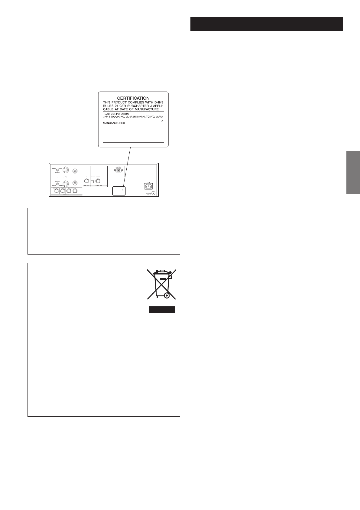
Analog audio output terminals
2 channel (FRONT)
Use either the XLR or RCA (pin) FRONT terminals for analog
stereo output.
If your amplifier has balanced XLR analog audio inputs,
connect the XLR jacks on the unit to the amplifier’s XLR
jacks, otherwise use the RCA (pin) connections.
5.1 channel
For surround (5.1) amplifiers with analog inputs, also use the
RCA (pin) SURROUND pair, CENTER and SUBWOOFER
connections (in addition to the FRONT pair).
<
If you are connecting only 2 channels, use the 2CH/MULTI
button on the remote control to select “2 ch”. For surround
sound with six speakers connected, you can select either
“2ch” or “5.1 ch” mode. Note that if multi-channel
program material is played and 2-channel mode is selected,
the multi-channel material will be down mixed to two
channels, and output through the L and R front outputs.
Digital audio output terminals
Digital audio from CD is output from these terminals.
The unit may be connected using either coaxial or optical
(TOS) commercially available cables to amplifiers, or to
digital audio devices such as CD recorders, etc.
COAXIAL: Use RCA (pin) digital audio cable
OPTICAL: Use optical digital audio cable (TOS)
<
The optical terminal is covered by a shutter. Make sure that
the cable is firmly inserted, but do not force the cable when
connecting it or removing it, in order not to cause damage
to the unit.
<
The DIGITAL OUT terminals cannot output the digital audio
from Super Audio CDs.
B
A
i.LINK (AUDIO) terminal
In addition to the digital audio from CD, the digital surround
audio from Super Audio CDs can be output from this
terminal. To enjoy surround sound from a Super Audio CD,
connect the i.LINK (AUDIO) terminal to a suitably equipped
surround sound amplifier.
Use a commercially available S400 compatible i.LINK
(IEEE1394) 6pin cable to connect the unit to an amplifier.
<
When using this terminal, set the Digital Out to “ON”, and
the i.LINK output setting to “60958” or “PCM” (see pages
21, 16-18).
<
See page 24 for further details on i.LINK.
Word sync connector
This allows the use of an externally-generated word clock
connection, using a commercially available BNC coaxial
cable.
Devices producing such a suitable clock signal include
external D-A converters, or dedicated word clock
generators. Connect the SYNC OUT (or WORD OUT) of such
a device to the unit.
SIGNAL GND connection
Use a commercially available PVC-covered cord to connect
the signal ground terminal on the unit to the amplifier signal
ground.
<
Note that this is NOT an electrical safety ground (earth).
Power cord receptacle
Connect the power cord to the power cord receptacle and
connect the power plug to an AC wall outlet after all other
connections have been made.
<
Use only the supplied Esoteric power cord. Use of other
power cords may result in fire or electric shock. Unplug the
power cord when you are not going to use the unit for an
extended period of time.
F
E
D
C
CAUTION:
<
Switch off the power to all equipment before making
connection.
<
Read the instructions of each component you intend to use
with this unit.
<
Be sure to insert each plug securely. To prevent hum and
noise, avoid bundling the signal interconnection cables
together with the AC power cord or speaker cables.
Page 10

10
Front panel features
Disc type indicator
Shows the type of disc currently loaded.
TRACK indicator
Indicates that the track number is being shown.
TOTAL indicator
Indicates that the total time is being shown.
REMAIN indicator
Indicates that the remaining time is being shown.
DOWN MIX indicator
Lights to show that a multi-channel source has been down
mixed to the analog outputs.
5.1CH indicator
Lights to show that 5.1 analog output has been selected
Channel indicators
Light to show which surround channels are currently in use.
Message area
Alphanumeric display to show playback times, status
messages, etc.
REPEAT indicator
Lights when repeat play is selected
Pause indicator
Lights when playback is paused.
Playback indicator
Lights when playing back.
k
j
i
h
g
f
e
d
c
b
a
A B D E H I JF KGC
Front Panel
POWER
Use this button to turn the unit on and off. When the unit is
on, the ring surrounding the button lights up.
MODE
Use this button to change settings of Word sync, DAC,
priority playback area, and i.LINK output.
DAC indicator
Shows the type of DAC currently selected.
Remote control sensor
Receives signals from the remote control unit. Point the
remote control unit at this sensor when operating the remote
control unit.
Display
Disc tray and shutter
OPEN/CLOSE
Use this button to open and close the disc tray.
STOP
Use this button to stop playback. When playback is stopped,
the ring surrounding the button lights up.
PLAY
Use this button to start playback. When a disc is being played
back, the ring surrounding the button lights up.
PAUSE
Use this button to pause playback. When playback is
temporarily paused, the ring surrounding this button lights
up.
SKIP (.//)
Use these buttons to for skip operations. Pressing and holding
these buttons for more than a second changes the scanning
speed.
K
J
I
H
G
F
E
D
C
B
The equipment draws nominal non-operating power from
the AC outlet with its POWER switch in the off position.
A
a
b
c
g
h
j
ik
d
e
f
Display
Page 11

11
ENGLISH
Understanding the remote control unit
Number buttons
Use these buttons for selecting tracks by number, etc.
2CH/MULTI
Use this button to switch between two-channel (stereo) and
multi-channel surround audio output.
PLAY AREA
Use this button to select the playback area of Super Audio
CDs.
SCAN (m/,)
Use these buttons for fast scanning during playback.
STOP
Use this button to stop playback.
PLAY
Use this button to start playback.
Cursor buttons and ENTER
Use these buttons in the setup menu.
SETUP
Use this button to enter or exit the setup menu.
OPEN/CLOSE
Use this button to open and close the disc tray.
CLEAR
Use this button to clear entry errors, etc.
DISPLAY
Use this button to change the display mode.
FL DIMMER
Use this button to change the brightness of the front panel
display.
REPEAT
Use this button to set the repeat playback mode.
PROGRAM
Use this button to program tracks.
MUSIC SKIP (.//)
Use these buttons to for skip operations.
PAUSE
Use this button to pause playback.
RETURN
Use this button to go back a level in the setup menu.
Q
P
O
N
M
L
K
J
I
H
G
F
E
D
C
B
A
A
B
C
E
H
G
D
F
K
P
Q
I
J
L
M
O
N
Page 12

12
Playback
Opening and closing the tray
1
5
2 43
Turn the unit on.
1
Each press of the POWER button turns the unit on and off.
The ring surrounding the POWER button and the display light
up when the unit is turned on.
Press the OPEN/CLOSE button.
2
The shutter opens and the disc tray slides out.
<
The tray opens after a few seconds (this delay is normal and is
due to movement of the VRDS and other mechanisms within
the unit).
Insert the disc, label side up.
3
< Make sure the disc is centered in the tray in order to avoid
any malfunction or jamming of the tray or damage to the disc
itself.
Press the OPEN/CLOSE button again.
4
The disc tray and shutter close. Take care to avoid pinching
your fingers in the moving tray.
< The unit reads the disc, which takes some time due to the
reading and storing of the disc’s table of contents.
Press the PLAY button to start playback.
5
Pausing playback
Press the PAUSE button to pause playback (the ring
surrounding the PAUSE button on the main unit lights).
Press PLAY or PAUSE to restart playback.
Stopping playback
Press the STOP button (the ring surrounding the STOP button
on the main unit lights).
Pressing OPEN/CLOSE opens the tray if it is closed, and closes
it if it is open. When the tray is opened during playback, it
may take a few seconds before the disc is “unloaded” and
the tray opens.
Page 13

13
ENGLISH
There are two types of Super Audio CDs, regular ones that
contain 2-channel stereo and multi-channel stereo and hybrid
discs (two-layer discs) that contain Super Audio CD and
regular CD data.
When a hybrid Super Audio CD is loaded and when the
playback is stopped, press the PLAY AREA button to select a
playback area.
<
The setting described on pages 16-18 allows you to
determine which layer will be first selected for playback (the
priority playback layer).
Selecting the playback area
Skipping playback
Press the MUSIC SKIP button (. or /) repeatedly until
the desired track is found. The selected track will be played
from the beginning.
<
If the . button is pressed once during playback, playback
returns to the start of the current track. If it is pressed within
one second from the start of the track, playback returns to
the start of the previous track (so pressing the button twice in
quick succession will skip back two tracks, etc.).
<
If tracks are skipped while playback is paused or stopped,
playback is paused or stopped at the start of the selected
track.
Selecting a track
Use the number button to select tracks for playback. Use the
+10 button to enter the first digit of numbers greater than 9
(repeated presses show 1-, 2-, 3- etc.) and the single digit
buttons (0 through 9) for the second digit, or single-digit
track numbers.
Playback starts from the selected track, regardless of whether
the number is selected during playback or playback is stopped
or paused.
Use the CLEAR button to clear mistaken entries.
Fast scanning
When playing back, use the SCAN button (m or ,) to
move backwards and forwards. Press PLAY to restart playback
at normal speed at the desired location.
Repeated presses of the SCAN buttons changes the scanning
speeds. There are three speeds:
Fast (1) q
Fast (2) q Fast (3) q Play (normal speed)
<
You can also use the SKIP buttons of the main unit. To start
scanning (or to change the scanning speed), press and hold
the SKIP button for more than one second.
Page 14

14
Programmed playback
Programmed playback allows up to 30 tracks to be played
back in the order you decide.
Press the PROGRAM button (either when playing back
or stopped).
If a track is currently playing back, this track is added as the
first item in the programmed playback list.
1
Use the number buttons to add tracks to the
programmed playback list.
2
Use the +10 button and 0 through 9 buttons in exactly the
same way as when selecting tracks.
Continue pressing the number buttons to add tracks.
<
Clear mistakes with the CLEAR button (the last entry is
cleared)
<
You can only select tracks on the disc (in other words, if the
disc has six tracks, you cannot program track 7!).
Finish the programming by pressing the PLAY button.
Programmed playback begins (if the disc is actually being
played back while you are setting the program order, there’s
no need to press PLAY).
3
Clearing the last track from the list
Press the CLEAR button to clear the last track from the list.
Adding tracks to the list
Use the number buttons to add tracks to the list.
Clearing the whole program
Press the PROGRAM button to clear the program (playback
continues from the current point).
The OPEN/CLOSE or the POWER button also clears the
program.
Track number Number in programmed list
Page 15

15
ENGLISH
Repeat mode
< Halting playback stops the repeat mode.
<
The following buttons cancel repeat mode:
STOP, OPEN/CLOSE, POWER.
Track repeat
When this is selected, the currently-selected track repeats. If
another track is selected during repeat playback, the newlyselected track repeats.
Disc repeat
The whole contents of the disc are repeated.
Programmed repeat
If programmed playback has been set up, the whole program
is repeated.
Pushing the REPEAT button cycles between REPEAT PGM
(program repeat) and REPEAT OFF (programmed playback
takes place).
Use the REPEAT button to select the repeat mode for
playback. Repeated presses of the REPEAT button cycle
between the following options:
REPEAT TRK
(track repeat)
REPEAT DSC
(whole disc repeat)
REPEAT OFF
(no repeat)
Display dimming
The display on the main unit can be dimmed to suit the
environment in which you listen to music. There are three levels
and an “off” setting.
Use the FL DIMMER button to cycle between these
settings.
Note that the OFF setting is not memorized when the power is
turned off. When the unit is switched off with the display off,
and then turned on again, the display is reset to the minimum
brightness.
Page 16

16
Changing the display mode
During playback, it is possible to change the display as shown
here.
< The DISPLAY button doesn’t work during programmed
playback.
Elapsed time of current trackCurrently playing track
Time remaining for current track
Total elapsed time (disc)
Total time remaining (disc)
Repeatedly press the MODE button to select the menu
item to be changed.
<
If you leave the unit idle for 10 seconds, the setting mode will
be cancelled.
Use the SKIP buttons (.//) to select the options
within the menu item.
Individual menu functions are described on pages 17-18.
Repeatedly press the MODE button until the display
returns normal (or leave the unit idle for 10 seconds) to
exit the setup mode.
Pressing the STOP button also finishes the setup mode.
<
Switching off the power without exiting the setup mode may
cause problems. Do not turn the unit off.
<
Settings are stored even when power is turned off and the
unit is unplugged. If left unplugged for an extended period,
the settings may be lost.
3
2
1
MODE
(normal display)
WORD DAC LAYER
Page 17

17
ENGLISH
Setting the Word sync, DAC, priority playback area, and i.LINK output (1)
Available menu item and options
WORD (Word sync)
Use this feature to lock your entire system to a single sync
signal (clock) by connecting this unit to the Esoteric G-0s or
similar device that outputs a sync signal.
“ON” or “OFF” are available.
<
This unit is ready for the clocks up to 176.4 kHz and switches
itself depending on an incoming signal.
< Make connections to the WORD SYNC terminal before
turning on the unit.
< When the unit is synchronizing to the sync signal, the ring
surrounding the MODE button flashes. When it is locked, the
button lights.
<
If no valid sync signal is received, the display shows “No
Word!” or “Wrd Unlck!”.
(Continued on the next page.)
DAC (D/A converter)
This unit is equipped with the following DA converters:
• DSD DAC for DSD signals (AD1955 from Analog Devices, Inc.)
• 1-bit DAC for PCM signals (AD1955 from Analog Devices,
Inc.)
• Multi-bit DAC for PCM signals (PCM1704 from Burr-Brown)
This setting allows you to determine which DAC will be
selected for playback.
REF. (Reference)
The unit automatically selects the proper DAC for the disc
currently loaded.
The selection depends on the Analog Out (see page 21).
M.bit (Multi-bit)
Use the Multi-bit DAC.
DSD signals from Super Audio CDs are converted to PCM
signals.
The MULTI-BIT indicator lights during playback.
1 bit
Use the 1-bit DAC.
DSD signals from Super Audio CDs are converted to PCM
signals.
The 1-BIT indicator lights during playback.
DSD
Use the DSD DAC.
PCM signals from CDs are converted to DSD signals (1 bit, 64
fs).
The DSD indicator lights during playback.
Page 18

18
i.LINK
Used to select an i.LINK output setting.
When using the i.LINK terminal, select “60958” or “PCM”,
and set the Digital Out to “ON”.
60958
DSD signal is output during playback of a Super Audio CD.
The digital signal in IEC60958 format is output during
playback of a CD.
PCM
DSD signal is output during playback of a Super Audio CD.
Linear PCM digital signal is output during playback of a CD.
<
Some amplifiers may regard this signal as DVD-Audio.
OFF
Select this when you don’t use the i.LINK (AUDIO) terminal.
No signal is output from the i.LINK (AUDIO) terminal.
<
There is no difference between 60958 and PCM as far as
Super Audio CD playback is concerned.
< Set the Analog Out setting to “Multi ch” to output the
surround sound from a Super Audio CD.
When the Analog Out is set to “2ch”, the multi-channel
sound is down mixed to 2 channels.
<
In case you experience any problem with the audio output,
read the instructions of the connected component to check
the adaptable format.
<
If the component connected via the i.LINK terminal is
compatible with the flow rate control, the connected
component will work in the flow rate control mode.
Setting the Word sync, DAC, priority playback area, and i.LINK output (2)
LAYER (priority playback area)
There are two types of Super Audio CDs, regular ones that
contain 2-channel stereo and multi-channel stereo, and
hybrid discs (two-layer discs) that contain Super Audio CD
and regular CD data.
This setting allows you to determine which layer will be first
selected for playback (the priority playback layer) with a
hybrid Super Audio CD.
SACD
This mode gives priority to the Super Audio CD layer.
The 2-channel layer is played when the Analog Out is set to
“2ch”. The multi-channel layer is played when the Analog
Out is set to “Multi ch”.
CD
This mode gives priority to the CD layer.
< Selecting a layer that is not on the disc results in playback of
the alternative layer that is found on the disc.
< A change of playback layer using the PLAY AREA button is
overridden by the LAYER setting when a different disc is
loaded.
Page 19

19
ENGLISH
Settings (introduction)
Turn on the main unit.
1
Press the SETUP button to enter the setup menu.
2
“AudioSetup” appears on the front panel display.
<
Although it is possible to enter the setup menu while
playback is continuing, not all menu functions will be
available. Expand the number of available functions by
pressing the STOP button.
<
Exit the setup menu by pressing SETUP once again.
Use the cursor buttons to navigate the menus.
3
When a option marked with “>” is displayed, use the up
or down cursor buttons to change the setting, and press
the ENTER button to confirm the entry.
4
Exit the setup menu by pressing SETUP once more.
5
< Refer to the Setup Menu Chart on the next page.
<
The options you can change are marked with “>”.
<
Use the left and up cursor buttons (or the RETURN button) to
go back a level in the setup menu.
< When a numerical value (such as speaker distance) is
changed, the value is confirmed without pressing the ENTER
button.
<
Individual menu functions are described on pages 21-23.
<
Repeat steps and as required.
43
Page 20

20
AudioSetup GeneralSet
Analog Out SP Setup
DigitalOut
CD Direct
SP Size
Distance L/R *.*m
C *.*m
SR/SL *.*m
SP Level
L/R Size
C Size
SR/SL Size
SW ON/OFF
LR ***.*dB
C ***.*dB
SR ***.*-dB
SL ***.*dB
SW ***.*dB
Test Start
Test Tone
options options
options
options
options
options
options
options
options
options
options
options
options
options
options
options
Settings (Setup Menu Chart )
Page 21

21
ENGLISH
Settings (Audio Setup)
Analog output (Analog Out)
When a option marked with “>” is displayed, use the up or
down cursor buttons to change the setting, and press the
ENTER button to confirm the entry.
2ch
Outputs 2-channel audio from the the i.LINK (AUDIO) and the
2ch analog audio output terminals (FRONT L and R).
If multi-channel program material is played, the multi-channel
material will be down mixed to two channels, and the DOWN
MIX indicator lights on the display.
Multi ch
The unit outputs the multi-channel surround sound.
Select this when the i.LINK (AUDIO) terminal or the 5.1ch
analog audio output terminals are connected to a surround
sound amplifier.
<
5.1CH indicator lights when “Multi ch” is selected.
<
Note that if “Multi ch” is selected, only the front L/R sound of
the multi-channel material will be output from the FRONT L
and R terminals.
<
Note that the audio volume changes when the mode is
changed between 2-channel to multi-channel.
< Speakers should be set up properly for multi-channel use. See
page 22 for details.
< You can also use the 2CH/MULTI button of the remote
control unit to select either “2ch” or “Multi ch”.
When playback is stopped, press the 2CH/MULTI button.
Digital output (DigitalOut)
When a option marked with “>” is displayed, use the up or
down cursor buttons to change the setting, and press the
ENTER button to confirm the entry.
ON
Audio is output from the i.LINK (AUDIO) terminal and the
DIGITAL OUT terminals.
OFF
Audio is not output from the i.LINK (AUDIO) terminal and the
DIGITAL OUT terminals. If you are not using these terminals,
we suggest that you use this OFF setting for better analog
sound.
<
Digital sound from Super Audio CDs cannot be output from
the DIGITAL OUT terminals.
CD Direct
When a option marked with “>” is displayed, use the up or
down cursor buttons to change the setting, and press the
ENTER button to confirm the entry.
Direct
Speaker setting is bypassed.
Normal
The speaker setting you have made is used.
Select this setting when the i.LINK (AUDIO) terminal or the
5.1ch analog audio output terminals are connected to a
surround sound amplifier.
Page 22

22
Settings (Speaker Setup for the i.LINK and the 5.1ch analog audio output terminal)
Use these speaker setup menus when the i.LINK
(AUDIO) terminal or the 5.1ch analog audio output
terminals are connected to a surround sound amplifier,
and when you don’t use the speaker menus of the
amplifier.
There is no need for this setup when not using the i.LINK
(AUDIO) terminal or the 5.1ch analog audio output terminals,
or when you use the speaker menus of the amplifier. In this
case, leave this setup as it is (factory settings).
<
This setup has an effect on the sound output from the i.LINK
(AUDIO) terminal and the analog audio output terminals
when the Analog Out is set to “Multi ch” and the CD Direct
is set to “Normal”.
Speaker Size (SP Size)
Select the size (Large or Small) independently for the L/R
(front pair of speakers), the C (center speaker) and the SR/SL
(surround pair of speakers). Turn the subwoofer (SW) ON or
OFF (if you have no subwoofer).
Large
Select this when the connected speakers can fully reproduce
bass frequencies.
Small
Select this when the connected speakers are rather small and
cannot reproduce bass frequencies.
When this setting is selected, bass frequencies are output
from the subwoofer (if no subwoofer is connected, from the
front speakers).
OFF
Select this when no speaker is connected.
ON (subwoofer only)
Select this when a powered subwoofer is connected.
<
When the front speaker is set to “Small”, the subwoofer is
set to “ON” automatically. You cannot set the subwoofer
“OFF”.
<
For the center and surround pair options, if these speakers are
not physically present, you can select OFF to prevent any
output from those channels (you cannot turn off the front L/R
pair). Any speakers turned off will down mix to the other
enabled channels.
<
The down mix may affect the overall volume.
<
Adjust the relative levels of the speakers using the SP Level
setting (and the volume knob of the subwoofer).
Page 23

23
ENGLISH
Speaker distance (Distance)
This setup is effective in the following case only:
Set the DAC mode to “M.bit” or “1bit”, play Super Audio
CDs, and output sound from the 5.1ch analog output
terminals.
This setting has no effect on the i.LINK (AUDIO) terminal.
Ideally, the speakers should be placed so that they are all the
same distance from the listening position. If this is not
possible, you should use this method described here to adjust
them individually. It is also possible to adjust all distances
together. The point of these settings is to provide the best
synchronization between sound and image by delaying the
sound by an appropriate amount. The subwoofer is not
included in this setting (the placement of the subwoofer is
less critical than that of other speakers).
The L/R setting changes the distance of all speakers together.
Pressing the up button adds 0.1m to each value, and pressing
the down button subtracts 0.1m from each value.
Distances are measured in meters (1 meter = just over 3 feet,
and 0.1 meter = about 4 inches).
Carry out this operation first before setting the other speaker
distances.
After setting the L/R, C and SR/SL speaker distances together,
you can now set the center and surround pair distances. The
minimum distance for these is 0m and the maximum is 9m,
with the additional restrictions described here.
<
The distance that you set for the center speaker cannot be
greater than the distance set for the L/R pair and must be
within 1.7m of that L/R distance.
So for example, if the distance to the L/R pair is set to 5.0m,
the center distance must be between 3.3m (5 – 1.7) and 5m.
<
The distance that you set for the SR/SL surround pair cannot
be greater than the distance set for the L/R pair (and must be
within 9m of that distance).
So with the L/R pair set at 5m, the SR/SL pair distance can be
set from 0m to 5m.
Speaker levels (SP Level)
Use this to set the relative levels of the speakers. You can set
the L/R pair together, and the center, and surround rear pair
independently, as well as the subwoofer. The maximum value
you can set here is 0dB and the minimum is –12dB, with
settings made in 0.5dB increments.
1. Select “Test Start” and press the ENTER button.
The unit outputs test tone from each channel in turn at the
specified level for each channel.
< Adjust the master volume of your amplifier to the normal
listening level.
<
Test tone from subwoofer may be nearly inaudible. Check the
level of subwoofer using source material which contains low
frequency sound.
<
The unit won’t output test tone when “60958” is selected.
Select “PCM” to use test tone (see page 18).
<
The unit won’t output test tone when a Super Audio CD is (or
had been) loaded. In this case, remove the disc, turn the unit
off and on, and try again.
2. Select a speaker using the up or down cursor buttons.
3. Press the right cursor button.
4. Adjust the levels using the up or down cursor buttons.
5. When the setting has been finished, press the SETUP
button to exit the setup menu.
Test tone length (Test tone)
Select the Test Tone menu item, and choose between 2, 5
and 10 seconds. This represents the length of time that the
test tone is output from each speaker when Test Start is
selected.
Page 24

24
i.LINK (IEEE 1394)
The i.LINK is also known as IEEE 1394, an international
specification.
This unit is i.LINK (AUDIO) ready.
By connecting an i.LINK (AUDIO)-capable device to the i.LINK
(AUDIO) terminal on this unit using an i.LINK cable, you can
transmit Super Audio CD multi-channel signals that could not be
transmitted but in analog format in the past can be transmitted
in its original digital format, in addition to the capability of
transmitting 2-ch linear PCM data and multi-channel compressed
audio signals.
If you have multiple i.LINK-capable devices, you can connect
them through other devices to transmit data between them, so
you don’t need to be concerned with the order of connection.
Copyright protection system DTCP
To play back audio sounds recorded on Super Audio CD using
i.LINK, both the player and the D/A converter need to be
compliant to the copyright protection system DTCP (Digital
Transmission Content Protection).
This unit is DTCP compliant.
Data transfer rate
There are three transfer rates: 100 Mbps (S100), 200 Mbps
(S200), and 400 Mbps (S400). This unit is capable of transferring
data at a maximum 400Mbps.
For connection to an i.LINK-capable device, use a commercially
available S400-compliant 6-pin i.LINK cable.
When connecting multiple i.LINK-capable devices, avoid
connecting a device having a slow transfer rate between devices
having high transfer rates since this reduces the transfer rate of
the whole system. Connect devices having high transfer rates
towards the source as far “up-stream” as possible.
NOTES
<
Among the i.LINK formats there are “MPEG-2 TS” for BS
digital sources and “DV” for digital video for DVD recorders,
as well as the “i.LINK (AUDIO)” (A&M Protocol). Never
connect devices that are not compatible with i.LINK (AUDIO)
to this unit. If you do, this unit and other components may
not operate normally and may also become damaged.
<
In the process of data transfer, avoid plugging/unplugging the
i.LINK cables in use or switch on/off the power.
< Among i.LINK-capable devices, there are some that, if not
turned on, are not capable of relaying data.
< Some i.LINK-capable devices will not respond to this unit's
command. This is normal and is due to incompatibility among
i.LINK devices.
<
The receiving device may not support the output modes of
this unit. Read through the instruction manual of devices you
want to connect before making any connections.
How to connect multiple i.LINK-capable
devices
Daisy chain connection
You can daisy chain up to 17 devices including this unit.
Connection in tree structure
If you are using a device having three or more i.LINK connectors,
you may want to branch out the connections. This way of
connection allows you to connect up to 17 devices including this
unit.
Your system does not work if data is fed back to the output
device. Be careful not to create a loop.
i.LINK-capable
device
i.LINK-capable
device
i.LINK-capable
device
i.LINK-capable
device
i.LINK-capable
device
i.LINK-capable
device
i.LINK-capable
device
i.LINK-capable
device
i.LINK-capable
device
i.LINK-capable
device
i.LINK-capable
device
i.LINK-capable
device
i.LINK cable
i.LINK-capable
device
i.LINK-capable
device
i.LINK-capable
device
The i.LINK interface of this unit is designed in accordance with
the following specifications:
1)IEEE Std 1394a-2000, Standard for a High Performance
Serial Bus
2) Audio and Music Data Transmission Protocol 2.0
This unit is compliant with IEC 60958 bitstream, DVD-Audio,
Super Audio CD in the AM824 sequence adaptation layers of
this protocol.
Page 25

25
ENGLISH
Troubleshooting
In case you experience any problem with this unit, please take
the time to look through this chart and see if you can solve the
problem yourself before you call your dealer.
No power
e
Check the connection to the AC power supply. Check and
make sure the AC source is not a switched outlet and that,
if it is, the switch is turned on. Make sure there is power to
the AC outlet by plugging another item such as a lamp or
fan.
e
Press the POWER button of the main unit to turn it on.
Remote control doesn’t work.
e
Press the POWER button of the main unit to turn it on.
e
If the batteries are dead, change the batteries.
e
Use remote control unit within the range (7m/ 23ft.) and
point at the front panel.
e
Clear obstacles between the remote control unit and the
main unit.
e
If a strong light is near the unit, turn it off.
Severe hum or noise is heard.
e
Place the unit as far away from a TV as possible.
e
Make sure the line cords and speaker cables are as far away
from the AC supply as possible.
Will not play.
e
Reload the disc with the label side UP.
e
This unit cannot play such discs as CD-ROMs. Use a playable
disc.
e
If the disc is dirty, clean the surface of the disc.
e
A blank disc has been loaded. Load a prerecorded disc.
e
If the unit is condensed, leave the unit for one or two hours
with the power turned on.
e
If another operation is still in process, wait a moment and
try again.
Sound skips.
e
Place the unit on a stable place to avoid vibration and shock.
e
If the disc is dirty, clean the surface of the disc.
e
Don’t use scratched, damaged or warped discs.
There is no sound or only a very low-level sound is heard.
e
Check that the amplifier and speakers are connected
securely.
e
Check the operation of the amplifier.
e
Check the audio output setting.
e
When the amplifier is connected via the i.LINK (AUDIO) or
the DIGITAL OUT terminal, set the Digital Out setting to
“ON”.
e
The sound is muted during pause. Press the PLAY button to
resume normal playback.
No multi-channel audio output.
e
Set the Analog Out to “Multi ch”.
e
Change the speaker configuration if necessary.
e
Super Audio CDs may have more than one playback area,
not all of which contain multi-channel audio data. Choose a
multi-channel area.
Overall volume is low, or balance between speakers is
strange.
e
A speaker’s level (or that of a pair of speakers) has been set
up too low or too high in the speaker setup. Correct the
levels.
The speaker settings are ignored.
e
Set the Analog Out to “Multi ch”.
e
Set the CD Direct to “Normal”.
No digital audio output.
e
Check that the Digital Out setting is set to “ON”. When using
the i.LINK (AUDIO) terminal, set the i.LINK output setting to
“60958” or “PCM”.
e Digital audio from a Super Audio CD cannot be output from
the DIGITAL OUT terminals. Use the i.LINK (AUDIO) terminal.
The MODE button flashes, and the display shows “No
Word!”
e
The word sync mode is selected, but there is no clock
source. Turn the word sync mode off.
e
No word clock is being received. Check cables, connections,
and settings of the clock generator.
The MODE button flashes, and the display shows “WRD
UNLCK!”
e
Invalid word sync signal is received. Check the setting of the
clock generator.
If normal operation cannot be obtained, unplug the power
cord from the outlet and plug it again. This resets the
internal micro-computer which can be disturbed during
electrical storms, power interruptions, et cetera.
Page 26

26
Specifications
General
System . . . . . . . . . . . . . . . . . . . . . . . . . . . . . . . . . . . . . . . . . . . . . . . . . . . . Super Audio CD and CD
Power supply
Europe model . . . . . . . . . . . . . . . . . . . . . . . . . . . . . . . . . . . . . . . . . . . . . . . . . . AC 230 V, 50 Hz
U.S.A./Canada model . . . . . . . . . . . . . . . . . . . . . . . . . . . . . . . . . . . . . . . . . . . . AC 120 V, 60 Hz
Korea model . . . . . . . . . . . . . . . . . . . . . . . . . . . . . . . . . . . . . . . . . . . . . . . . . . . AC 220 V, 60 Hz
Power consumption . . . . . . . . . . . . . . . . . . . . . . . . . . . . . . . . . . . . . . . . . . . . . . . . . . . . . . . . 39 W
Weight . . . . . . . . . . . . . . . . . . . . . . . . . . . . . . . . . . . . . . . . . . . . . . . . . . . . . . . . 25 kg (55-1/16 lb)
External dimensions (W x H x D) . . . . . . . . . . . . . . . . . . . . . . . . . . . . . . . . . . . 442 x 153 x 353 mm
(17-3/8” x 6” x 13-7/8”)
Operating temperature . . . . . . . . . . . . . . . . . . . . . . . . . . . . . . . . . . . . . . . . . . . . . . . . +5˚C - +35˚C
Operating humidity. . . . . . . . . . . . . . . . . . . . . . . . . . . . . . . . . . . . . . 5% to 85% (no condensation)
Storage temperature . . . . . . . . . . . . . . . . . . . . . . . . . . . . . . . . . . . . . . . . . . . . . . . . . –20˚C - +55˚C
Audio output (Analog Audio)
Jacks . . . . . . . . . . . . . . . . . . . . . . . . . . . . . . . . . . . . . . . . . . . . . . . . . . . . . XLR jacks (2 channel) x 1
RCA jacks (5.1 channel) x 1
Maximum Output level (1 kHz, full scale) . . . . . . . . . . . . . . . . . . . . . . . . . . . . . . . . . 2.2 Vrms (RCA)
2.2 Vrms (XLR)
Frequency response . . . . . . . . . . . . . . . . . . . . . . . . . . . . . . . . . . . . . . . . . . . 5 Hz to 80 kHz (–3 dB)
Signal-to-Noise Ratio (S/N) . . . . . . . . . . . . . . . . . . . . . . . . . . . . . . . . . . . . . . . . . . . . . . . . . . 116 dB
Total harmonic distortion . . . . . . . . . . . . . . . . . . . . . . . . . . . . . . . . . . . . . . . . . . . 0.0015% (1 kHz)
Audio output (Digital Audio)
OPTICAL . . . . . . . . . . . . . . . . . . . . . . . . . . . . . . . . . . . . . . . Optical digital jack x 1, –15 to –21 dBm
COAXIAL . . . . . . . . . . . . . . . . . . . . . . . . . . . . . . . . . . . . . . . . . . . . . . . RCA jack x 1, 0.5 Vp-p/75 Ω
i.LINK. . . . . . . . . . . . . . . . . . . . . . . . . . . . . . . . . . . . . . . . . . . . . . . . . . . i.LINK (AUDIO) terminal x 1
Word Synchronization input format
Jack . . . . . . . . . . . . . . . . . . . . . . . . . . . . . . . . . . . . . . . . . . . . . . . . . . . . . . . . . . . . . . . . . . . . . BNC
Input level . . . . . . . . . . . . . . . . . . . . . . . . . . . . . . . . . . . . . . . . . . . . . . . . . . . . . . . . . 4.5 Vp-p/75Ω
The main unit can accept and synchronize to the following frequencies received from external
devices . . . . . . . . . . . . . . . . . . . . . . . . . . . . . . . . . . . . . . . . . . . . . . . . 44.1kHz, 88.2kHz, 176.4kHz
Accessories
Power cord x 1
Remote Control Unit (RC-941) x 1
Batteries (AA, R6, SUM-3) x 2
Felt x 3
Warranty card x 1
Owner
’
s manual x 1
• Design and specifications are subject to change without notice.
• Weight and dimensions are approximate.
• Illustrations may differ slightly from production models.
Page 27

FRANÇAIS
27
ATTENTION
<
N’exposez pas cet appareil au ruissellement ni aux
éclaboussures.
< Ne placez aucun objet contenant du liquide, tel qu’un vase,
sur l’appareil.
< N’installez pas cet appareil dans un espace confiné comme
une bibliothèque ou similaire.
< L’appareil tire un courant de veille nominal de la prise
secteur quand son interrupteur STANDBY/ON est en
position d’arrêt.
<
L’appareil doit être placé assez près de la prise de courant
pour que vous puissiez à tout moment attraper facilement
la fiche du cordon d’alimentation.
<
Un appareil de Classe ! doit être branché à une prise de
terre.
< Les batteries (ou le pack de batteries ou les batteries
chargées) ne devront pas être exposées à la chaleur
excessive telle que le soleil, le feu ou analogues.
Pour l’Europe
Mise au rebut de votre ancien appareil
1.Quand ce symbole de poubelle sur roues
barrée d’une croix est joint à un produit,
cela signifie que ce produit est couvert par
la Directive Européenne 2002/96/EC.
2. Tous les produits électriques et électroniques doivent être
jetés séparément des ordures ménagères via des collecteurs
désignés agréés par le gouvernement ou les autorités
locales.
3. La gestion correcte de l’élimination de votre ancien appareil
aide à prévenir les conséquences potentiellement négatives
pour l’environnement et la santé humaine.
4. Pour des informations plus détaillées sur la mise au rebut de
votre ancien appareil, veuillez contacter votre mairie, le
service de traitement des ordures ou le magasin dans lequel
vous avez acheté le produit.
Sommaire
Nous vous remercions pour l’achat d’un appareil Esoteric.
Lire ce manuel avec attention pour obtenir les meilleures
performances possibles de cet appareil.
Sommaire . . . . . . . . . . . . . . . . . . . . . . . . . . . . . . . . . . . . . . . . 27
Caractéristiques . . . . . . . . . . . . . . . . . . . . . . . . . . . . . . . . . . . 28
Avant utilisation . . . . . . . . . . . . . . . . . . . . . . . . . . . . . . . . . . . 29
Disques. . . . . . . . . . . . . . . . . . . . . . . . . . . . . . . . . . . . . . . . . . 30
Télécommande . . . . . . . . . . . . . . . . . . . . . . . . . . . . . . . . . . . . 31
Restauration des réglages d’usine . . . . . . . . . . . . . . . . . . . . . . 31
Connexions. . . . . . . . . . . . . . . . . . . . . . . . . . . . . . . . . . . . . . . 32
Description de la face avant . . . . . . . . . . . . . . . . . . . . . . . . . . 34
Comprendre la télécommande . . . . . . . . . . . . . . . . . . . . . . . . 35
Lecture . . . . . . . . . . . . . . . . . . . . . . . . . . . . . . . . . . . . . . . . . . 36
Saut de lecture . . . . . . . . . . . . . . . . . . . . . . . . . . . . . . . . . . . . 37
Sélection d’une plage . . . . . . . . . . . . . . . . . . . . . . . . . . . . . . . 37
Recherche rapide . . . . . . . . . . . . . . . . . . . . . . . . . . . . . . . . . . 37
Sélection de la zone de lecture . . . . . . . . . . . . . . . . . . . . . . . . 37
Lecture programmée. . . . . . . . . . . . . . . . . . . . . . . . . . . . . . . . 38
Mode Repeat (lecture en boucle). . . . . . . . . . . . . . . . . . . . . . . 39
Atténuation de l’afficheur . . . . . . . . . . . . . . . . . . . . . . . . . . . . 39
Changement du mode d’affichage . . . . . . . . . . . . . . . . . . . . . 40
Réglage de la synchro word, du DAC, de la zone
à lecture prioritaire et de la sortie i.LINK . . . . . . . . . . . . . . . 41
Réglages. . . . . . . . . . . . . . . . . . . . . . . . . . . . . . . . . . . . . . . . . 43
Sortie analogique (Analog Out) . . . . . . . . . . . . . . . . . . . . . 45
Sortie numérique (DigitalOut) . . . . . . . . . . . . . . . . . . . . . . 45
CD Direct . . . . . . . . . . . . . . . . . . . . . . . . . . . . . . . . . . . . . 45
Taille d’enceinte (SP Size) . . . . . . . . . . . . . . . . . . . . . . . . . . 46
Distance des enceintes (Distance) . . . . . . . . . . . . . . . . . . . 47
Niveaux des enceintes (SP Level) . . . . . . . . . . . . . . . . . . . . 47
Durée de la tonalité de test (Test tone) . . . . . . . . . . . . . . . 47
i.LINK (IEEE 1394) . . . . . . . . . . . . . . . . . . . . . . . . . . . . . . . . . . 48
Guide de dépannage . . . . . . . . . . . . . . . . . . . . . . . . . . . . . . . 49
Spécifications . . . . . . . . . . . . . . . . . . . . . . . . . . . . . . . . . . . . . 50
« Super Audio CD » est une marque déposée.
« DSD » est une marque déposée.
Le logo i.LINK est une marque commerciale de Sony
Corporation, déposée aux U.S.A. et dans d’autres pays.
Page 28

Le dernier mécanisme VRDS pour Super Audio CD (roulements
à billes spécialement conçus pour un mécanisme VRDS
optimal)
Le mécanisme VRDS maintient de façon sûre le disque sur la
platine dont le diamètre est exactement le même que celui du
disque. Ce système élimine complètement les vibrations
inhérentes aux supports amovibles et les vibrations indésirables
produites par les systèmes mécaniques. De plus, ce mécanisme
serre le disque avec une légère inclinaison de façon à compenser
le gauchissement ou la déformation, améliorant ainsi la précision
des axes optiques à la fois du capteur laser et de la surface gravée
du disque. C’est efficace pour réduire les erreurs lors de la lecture
des données sur le disque ainsi que pour prévenir les erreurs de
timing dues à un timing erratique d’acquisition des données.
Pour obtenir une rotation à haute vitesse avec la stabilité
supérieure requise par un lecteur de Super Audio CD, le X-01 D2
est équipé d’une platine en duralumin. Une technologie de
traitement spécialement développée a été employée pour
permettre le profilage de ce matériau léger normalement utilisé
en construction aéronautique.
Dans un projet de développement commun avec NSK Ltd., nous
avons développé des roulements à billes exclusifs, de haute
précision, pour le mécanisme VRDS. Les éléments mobiles réalisés
à partir de billes en céramique à usinage de précision assurent
une rotation ultra fluide. L’application d’une pré-charge à la paire
de roulements à billes assure une haute rigidité et une rotation
précise que n’ont pas les roulements conventionnels mais qui
sont nécessaires pour assumer l’ample plage de rotations allant
de la lecture de CD normal à celle de Super Audio CD.
Un pont en acier massif SS400 de 20 mm d’épaisseur supporte le
mécanisme pour contrôler les vibrations produites par la rotation
de la platine.
Moteur sans noyau avec aimants néodyme
Un nouveau moteur d’axe triphasé sans balais fournit la rotation
rapide et précise requise par la lecture de Super Audio CD. Avec
la fixation de la platine associée à l’emploi de roulements à billes
de précision, cela élimine les irrégularités de rotation et les
vibrations.
La recherche a démontré que le néodyme est le matériau
magnétique optimal pour cette application. Le néodyme absorbe
les changements d’alimentation électrique du moteur et exerce
une influence minimale sur les sections audio de l’appareil.
Capteur optique à angle constant monté sur chariot avec
contrôle rétroactif de la vitesse
En montant le capteur sur un chariot dont l’axe est rigide, la
lentille du capteur est maintenue à un angle constant. Le faisceau
laser, et par conséquent l’axe optique, gardent donc une
orientation verticale précise. Un moteur triphasé original
d’Esoteric, sans balais et avec détection d’élément Hall, pilote le
chariot et la vitesse de celui-ci est contrôlée pour asservir le
chariot lui-même de façon rétroactive, ce qui signifie que le
chariot a un fonctionnement très réactif et très souple.
Châssis robuste, rigide, avec support à trois pointes
L’appareil est basé sur une robuste plaque en acier de 5 mm
d’épaisseur, et est divisé en trois sections logiques, ce qui réduit
les interférences entre les composants de l’appareil. Des
28
montages à haute rigidité sont employés pour le mécanique de
disque VDRS.
Pour éliminer les vibrations, trois pieds solides (en acier
d’outillage) supportent l’appareil et l’isolent mécaniquement.
Des caractéristiques inégalables
Des performances dignes de ce tout dernier lecteur de Super
Audio CD aux fonctionnalités complètes ont été obtenues.
• Un transformateur de puissance intégrant un transformateur
numérique R-Core à haut rendement et un autre transformateur
pour l’analogique. De plus, les circuits d’alimentation sont séparés
pour le numérique et l’analogique.
• La carte audio des 2 canaux avant est agencée avec le canal droit
sur une carte et le canal gauche sur une autre.
• Sortie de Super Audio CD en son 5.1.
• Connexion i.LINK (compatible avec le contrôle de débit).
Convertisseurs audio N/A (DAC)
Le DAC DSD pour la lecture de Super Audio CD et le DAC
multibit pour la lecture de CD sont tous les deux montés sur les 2
canaux avant.
Un circuit convertisseur bidirectionnel, capable de traiter à la fois
les données DSD et PCM, est aussi monté pour que l’utilisateur
puisse pleinement bénéficier des caractéristiques de chacun, quel
que soit le type de disque.
La conversion de données PCM de CD en DSD, ou de données
DSD de Super Audio CD en PCM, permet la reproduction avec les
meilleures caractéristiques de DAC possibles pour les deux types
de données.
Le DAC DSD et le DAC multibit emploient chacun une paire de
sorties, + (positive) et - (négative), pour 1 canal (soit au total: 4),
et exploite leur addition et leur soustraction pour obtenir une
conversion N/A haute capacité.
Synchronisation word clock
Une horloge word clock maître venant d’un convertisseur N/A de
haute qualité ou d’un générateur d’horloge maître peut être
employée pour la synchronisation par horloge, ce qui entraîne
l’élimination quasiment totale de la gigue ou « jitter ».
Utiliser un signal d’horloge de haute qualité fourni par un
convertisseur N/A externe tel que le G-0/G-0s Esoteric procure
une qualité audio optimale.
Un volet d’obturation isole le mécanisme des influences
externes
Le mécanisme d’ouverture et de fermeture du tiroir est équipé
d’un volet d’obturation pour une plus grande précision et pour
éliminer les effets nuisibles de la pression sonore et des vibrations
externes sur les unités mécaniques. Quand il est fermé, le
dispositif de volet est mécaniquement arrimé à la face avant pour
l’empêcher de bouger.
La finition en aluminium brossé illustre la qualité de la
construction
Les panneaux avant, latéraux et supérieur sont en aluminium
brossé épais. La luxueuse finition correspond à la recherche
générale de la plus grande qualité possible, se reflétant dans des
détails comme le pourtour éclairé des boutons de commande et
le plateau de disque en aluminium fraisé.
Caractéristiques
Page 29

FRANÇAIS
29
Contenu du carton
Veuillez vérifier que les accessoires suivants sont bien présents à
l’ouverture du carton.
Télécommande x 1
Piles (AA, R6, SUM-3) x 2
Pieds en feutre x 3
Cordon d’alimentation x 1
Manuel du propriétaire x 1
Carte de garantie x 1
Conventions adoptées dans ce manuel
< Les instructions de ce manuel décrivent les commandes de la
télécommande. Vous pouvez aussi utiliser les boutons de la
face avant s’ils ont des noms identiques ou similaires à ceux
de la télécommande.
<
Les types de fonctions et d’opérations utilisables pour un
disque particulier varient selon les caractéristiques de ce
disque. Dans certains cas, ces fonctions et opérations peuvent
différer des descriptions données dans ce mode d’emploi.
<
Les illustrations employées dans ce mode d’emploi ne sont
données qu’à titre explicatif.
A lire avant l’emploi
< Comme l’appareil peut chauffer durant son fonctionnement,
laissez toujours assez d’espace autour de lui pour la
ventilation.
<
La tension électrique fournie à l’appareil doit correspondre à
celle imprimée sur sa face arrière. En cas de doute à ce sujet,
consultez un électricien.
<
Choisissez soigneusement le lieu d’installation de votre
appareil. Evitez de l’exposer directement au soleil et de le
placer près d’une source de chaleur. Evitez aussi les
emplacements sujets aux vibrations et de façon excessive à la
poussière, la chaleur, le froid ou l’humidité.
<
Ne placez pas l’appareil sur l’amplificateur/récepteur.
<
N’ouvrez pas l’unité car cela pourrait endommager les circuits
ou causer un choc électrique. Si un objet étranger vient à
pénétrer dans l’appareil, contactez votre revendeur ou le
service après-vente.
<
Pour débrancher le cordon d’alimentation de la prise secteur,
saisissez toujours sa fiche, ne tirez jamais sur le cordon.
< Pour garder propre le capteur laser, ne le touchez pas et
fermez toujours le tiroir de disque.
< N’essayez pas de nettoyer l’appareil avec des solvants
chimiques car cela pourrait endommager sa finition. Utilisez
un chiffon propre et sec.
<
Conservez ce manuel en lieu sûr pour vous y référer
ultérieurement.
Avant utilisation
Positionnement de l’appareil
De l’acier d’outillage durci de haute qualité est employé pour
les pieds à pointe, qui sont fermement attachés à la base du
lecteur. Bien que les patins de pied puissent sembler lâches, le
poids de l’appareil les immobilise et les sécurise, et cette
conception amortit et réduit efficacement les vibrations.
<
En raison de son poids, veillez à ne pas vous blesser quand
vous déplacez l’appareil. Faites vous aider si nécessaire.
<
Pour protéger les sols, etc., vous pouvez coller sous les patins
de pied les feutres fournis avec l’appareil.
Pin-point foot
Bottom plate
of the unit
Steel foot
Cover foot retaining screws
Cover foot
Faites attention à la condensation
Quand l’appareil (ou un disque) est déplacé d’un lieu froid à
un lieu chaud, ou s’il est employé après une soudaine hausse
de température, il existe un risque de condensation; la vapeur
de l’air peut se condenser sur le mécanisme interne, rendant
impossible un fonctionnement correct. Pour prévenir cela, ou
si cela se produit, laissez l’appareil allumé durant une ou deux
heures. Il se stabilisera alors à la température de son
environnement.
Entretien
Si la surface de l’appareil est sale, essuyez-la avec un chiffon
doux ou employez un nettoyant liquide neutre dilué. Veillez à
totalement essuyer toute trace de liquide. N’utilisez pas de
diluant, d’essence ou d’alcool car cela pourrait endommager
la surface de l’unité.
Pied à pointe
Pied en acier
Vis de maintien du patin de pied
Patin de pied
Plaque inférieure
de l’appareil
NE BOUGEZ PAS L’APPAREIL DURANT LA LECTURE
Durant la lecture, le disque tourne à haute vitesse. L’appareil
ne doit PAS être soulevé ni bougé durant la lecture. Cela
pourrait endommager le disque ou l’appareil.
POUR DEPLACER CET APPAREIL
Quand vous changez l’appareil de place ou quand vous
l’emballez pour le transporter, veillez à sortir le disque et à
refermer le tiroir du lecteur. Ensuite, appuyez sur
l’interrupteur d’alimentation pour éteindre l’appareil, puis
débranchez le cordon d’alimentation. Déplacer cet appareil
avec un disque à l’intérieur risque de l’endommager.
Page 30

30
Disques
CD audio :
• Disques de 12 cm ou 8 cm
• Audio numérique PCM linéaire
Les CD audio sont divisés en plages.
Super Audio CD :
• Simple couche, double couche ou hybride
• Disques de 12 cm ou 8 cm
• Audio numérique (DSD)
Les Super Audio CD sont divisés en plages.
A propos des CD-R/CD-RW
Les CD-R/RW enregistrés au format CD audio et correctement
finalisés sont lisibles. Mais en fonction de la qualité du disque
et/ou des conditions de l’enregistrement, certains CD-R et
CD-RW peuvent ne pas être lisibles.
Attention
<
Si vous enregistrez un disque à l’aide d’un ordinateur, même
s’il est enregistré à un format compatible, il peut ne pas être
lisible à cause des réglages du logiciel utilisé pour créer le
disque (consultez l’éditeur du logiciel pour plus
d’informations).
<
Les CD-R/CD-RW/DVD-R/RW non finalisés ne peuvent pas être
lus.
Types de disques lisibles par ce système
Ce lecteur peut lire les disques portant n’importe lequel des
logos suivants :
Les disques suivants ne peuvent pas être lus
par cet appareil
• DVD, CD-G, partie contenant des données des CD-EXTRA,
PHOTO CD, CD-ROM et DVD-ROM
• Disques produits illégalement
• Disques rayés ou endommagés
• Disques poussiéreux, sales ou portant des empreintes de doigt
Avertissement
Si vous essayez de lire de tels disques, il existe un risque qu’un
fort bruit soudain survienne dans les enceintes à haut volume
et endommage les haut-parleurs et votre audition.
Les disques protégés contre la copie, les DualDiscs et autres
disques qui ne se conforment pas à la norme CD peuvent ne
pas être correctement reproduits par ce lecteur. Si vous
utilisez de tels disques dans cet appareil, TEAC ESOTERIC
COMPANY ne pourra être tenu pour responsable d’aucune
conséquence et ne garantit pas la qualité de reproduction. Si
vous rencontrez des problèmes avec ces disques non
standards, vous devez contactez les éditeurs du disque.
Comment tenir le disque
< Placez toujours le disque dans le lecteur avec ses inscriptions
sur le dessus. (Les Compact Discs ne peuvent être lus ou
enregistrés que sur une face.)
<
Pour retirer un disque de son boîtier, appuyez sur la rosace au
centre du boîtier et sortez le disque, en le tenant
soigneusement par la tranche.
Comment sortir le disque
<
En cas de salissure du disque, essuyez la
surface de façon radiale (du trou central vers
l’extérieur) avec un chiffon sec et doux:
<
N’employez jamais de produits chimiques comme des bombes
pour disque, des bombes ou liquides antistatiques, de la
benzine ou du diluant pour nettoyer les disques. Ils
causeraient des dommages irréparables à la surface plastique
du disque.
<
Les disques doivent être remis dans leur boîtier après usage
pour éviter la poussière et les rayures qui pourraient causer
des « sauts » du capteur laser.
<
N’exposez pas les disques directement au soleil ou à une
humidité et température élevées durant des périodes
prolongées. Une longue exposition à de fortes températures
fera se gondoler le disque.
<
Ne faites pas reproduire un disque gondolé, déformé ou
endommagé.
Faire reproduire de tels disques peut causer des dommages
irréparables aux mécanismes de lecture.
<
Les CD-R et CD-RW sont plus sensibles aux effets de la
chaleur et des rayons ultraviolets que les CD ordinaires. Il est
important de ne pas les conserver dans un lieu soumis
directement aux rayons du soleil, et de les tenir éloignés de
sources de chaleur comme des radiateurs ou des appareils
électriques producteurs de chaleur.
<
Les disques imprimables ne sont pas recommandés car la face
avec étiquette peut être collante et risque d’endommager
l’appareil.
<
Ne collez pas de papiers ou de feuillets de protection sur les
disques et n’employez aucune bombe diffusant un
revêtement protecteur.
<
Utilisez un stylo feutre doux à base d’huile pour inscrire les
informations du côté inscriptible. N’utilisez jamais de stylo
bille ou à pointe dure car cela pourrait endommager la face
enregistrée.
<
N’employez jamais de stabilisateurs. L’emploi dans cet
appareil de stabilisateurs de CD disponibles dans le commerce
endommagera les mécanismes et conduira à leur mauvais
fonctionnement.
<
N’employez pas de disque de forme particulière (octogonal,
en forme de cœur, de taille carte de visite, etc.). Ce type de
disque peut endommager l’appareil:
<
En cas de doute sur l’entretien et le maniement d’un disque,
lisez les précautions données avec le disque, ou contactez
directement le fabricant du disque.
Page 31

FRANÇAIS
31
Si vous avez apporté beaucoup de changements à la
configuration, et si vous désirez revenir à des réglages connus,
ramenez l’appareil aux réglages d’usine comme suit :
1. Eteignez l’appareil et attendez au moins 30 secondes.
2. Appuyez sur la touche POWER en maintenant enfoncée
la touche STOP.
Toutes les mémoires sont effacées, et l’appareil revient aux
réglages d’usine.
Restauration des réglages d’usine
Remplacement des piles
La portée de la télécommande diminue quand les piles sont
faibles. Dans ce cas, remplacez-les par des neuves.
Précautions concernant les piles
<
Veillez à insérer les piles en respectant les polarités positive
« +
» et négative « _ ».
<
Utilisez des piles de même type. N’utilisez jamais en même
temps des types de piles différents.
< Des piles ou des batteries rechargeables peuvent
indifféremment être utilisées mais pas mélangées. Référezvous aux précautions inscrites sur leurs étiquettes.
<
Quand la télécommande ne doit pas être utilisée durant une
période prolongée (plus d’un mois), retirez ses piles pour
éviter qu’elles ne coulent. Si elles ont coulé, essuyez le liquide
répandu dans le compartiment des piles et remplacez les piles
par des neuves.
<
Ne faites pas chauffer et ne démontez pas les piles, et ne vous
débarrassez jamais des vieilles piles en les jetant dans un feu.
Notes d’utilisation
<
Pointez la télécommande vers le capteur du lecteur dans un
rayon de sept mètres. Il ne doit pas y avoir d’obstacles entre le
lecteur et la télécommande.
<
N’exposez pas le capteur de télécommande du lecteur
directement au soleil ou à une autre source lumineuse. Cela
pourrait faire fonctionner incorrectement la télécommande.
<
Notez que d’autres appareils à télécommandes peuvent
fonctionner incorrectement s’ils sont touchés par le
rayonnement infrarouge de cette télécommande.
Comment insérer les piles
Retirez le capuchon de la télécommande avec un tournevis.
Après avoir vérifié la polarité (+
/_) des deux piles AA,
insérez-les, replacez le capuchon et ses vis.
<
Faites attention de ne pas pincer les câbles avec le berceau
des piles.
Télécommande
Page 32

32
Connexions
Câble cinch (RCA)
Câble coaxial cinch (RCA)
Câble numérique optique
Câble coaxial BNC
Câble XLR
Brochage d’une XLR
symétrique
Amplificateur stéréo
Générateur d’horloge maître (G-0s etc.)
Convertisseur N/A
Amplificateur surround
Appareil audio numérique
(enregistreur de CD, platine MD, etc.)
Cordon d’alimentation fourni
Prise secteur
Amplificateur surround
Câble i.LINK
WORD SYNC OUT
AUDIO IN
A D
A
RL
i.LINK (AUDIO)
C
F
BB
E
R
5.1CH AUDIO IN
R
L
L
FRONTSURROUNDSUBWOOFER CENTER
DIGITAL IN (COAXIAL)
DIGITAL IN (OPTICAL)
Page 33

33
FRANÇAIS
ATTENTION :
<
Eteignez tous vos équipements avant de faire des
connexions.
<
Lisez les instructions concernant chaque élément que vous
désirez employer avec cet appareil.
<
Veillez à bien insérer chaque fiche. Pour éviter les
ronflements et les bruits, évitez de regrouper les câbles de
modulation (de signal) et le cordon d’alimentation ou les
câbles d’enceintes.
Prises de sortie audio analogique
2 canaux (FRONT)
Utilisez au choix les prises XLR ou cinch (RCA) nommées
FRONT pour la sortie analogique stéréo.
Si votre amplificateur a des entrées audio XLR analogiques
symétriques, reliez les prises XLR de l’appareil à celles de
l’amplificateur, sinon utilisez les connexions cinch (RCA).
5.1 canaux
Pour les amplificateurs surround (5.1) à entrées analogiques,
utilisez aussi les connexions cinch (RCA) de la paire
SURROUND, de CENTER et de SUBWOOFER (en plus de la
paire FRONT).
<
Si vous ne connectez que 2 canaux, utilisez la touche
2CH/MULTI de la télécommande pour sélectionner « 2 ch ».
Pour un son surround avec six enceintes connectées, vous
pouvez sélectionner le mode « 2ch » ou « 5.1 ch ». Notez
que si un programme multicanal est lu alors que le mode 2
canaux est sélectionné, il subira un mixage de réduction en
deux canaux, et sera produit par les sorties avant gauche et
droite (FRONT L et R).
Prises de sortie audio numérique
L’audio numérique du CD est produit par ces prises.
L’appareil peut être connecté, à l’aide d’un câble coaxial ou
optique (TOS) du commerce, à des amplificateurs ou à des
appareils audio numériques tels que des enregistreurs de
CD, etc.
COAXIAL: Utilisez un câble audio numérique cinch (RCA)
OPTICAL: Utilisez un câble audio numérique optique (TOS)
<
La prise optique est protégée par un obturateur. Assurezvous que le câble est fermement inséré, mais ne forcez pas
sur le câble quand vous le connectez ou le retirez, afin de ne
pas risquer d’endommager l’appareil.
<
Les prises DIGITAL OUT ne peuvent pas produire l’audio
numérique des Super Audio CD.
B
A
Prise i.LINK (AUDIO)
En plus de l’audio numérique du CD, l’audio numérique
surround des Super Audio CD peut être produit par cette
prise. Pour bénéficier du son surround d’un Super Audio CD,
reliez la prise i.LINK (AUDIO) à un amplificateur de son
surround convenablement équipé.
Utilisez un câble i.LINK (IEEE1394) 6 broches compatible
S400 du commerce pour brancher l’appareil à un
amplificateur.
<
Si vous utilisez cette prise, réglez le paramètre Digital Out
sur « ON », et le paramètre de sortie i.LINK sur « 60958 »
ou « PCM » (voir pages 45, 40-42).
<
Voir page 48 pour plus de détails sur i.LINK.
Connecteur word sync
Il permet la réception d’un signal word clock d’un
générateur externe, à l’aide d’un câble coaxial BNC du
commerce.
Parmi les appareils produisant un tel signal d’horloge
convenable se trouvent des convertisseurs N/A externes et
des générateurs word clock dédiés. Reliez à cette prise la
sortie SYNC OUT (ou WORD OUT) de tels appareils.
Connexion SIGNAL GND
Utilisez un fil conducteur à gaine PVC du commerce pour
relier ce bornier de masse du signal à la masse du signal de
l’amplificateur.
<
Notez bien que ce n’est PAS une mise à la terre de sécurité
électrique.
Embase de cordon d’alimentation
Branchez le cordon d’alimentation dans cette embase et la
fiche située à son autre extrémité dans une prise secteur
après que toutes les autres connexions aient été faites.
<
N’utilisez que le cordon d’alimentation fourni par Esoteric.
L’emploi de tout autre cordon pourrait entraîner un incendie
ou un choc électrique. Débranchez le cordon d’alimentation
si l’appareil doit rester inutilisé durant une période
prolongée.
F
E
D
C
Page 34

34
Description de la face avant
Indicateur de type de disque
Affiche le type de disque actuellement chargé.
Indicateur TRACK
Indique que c’est le numéro de plage qui est affiché.
Indicateur TOTAL
Indique que c’est la durée totale qui est affichée.
Indicateur REMAIN
Indique que c’est le temps restant qui est affiché.
Indicateur DOWN MIX
S’allume pour indiquer qu’une source multicanal a été mixée
en deux canaux pour les sorties analogiques.
Indicateur 5.1CH
S’allume pour indiquer que la sortie analogique 5.1 a été
sélectionnée.
Indicateurs de canaux
S’allume pour indiquer quels canaux surround sont
actuellement employés.
Aire de message
Affichage alphanumérique pour afficher les durées de lecture,
des messages de statut, etc.
Indicateur REPEAT
S’allume quand la lecture en boucle est sélectionnée.
Indicateur de pause
S’allume quand la lecture est en pause.
Indicateur de lecture
S’allume pendant la lecture.
k
j
i
h
g
f
e
d
c
b
a
Face avant
POWER
Utilisez cet interrupteur d’alimentation pour allumer et
éteindre l’appareil. Quand l’appareil est en service, le
pourtour de l’interrupteur est allumé.
MODE
Utilisez cette touche pour changer les réglages de synchro
word, convertisseur N/A, zone à lecture prioritaire et sortie
i.LINK.
Indicateur de convertisseur N/A (DAC)
Affiche le type de convertisseur N/A (DAC) actuellement
sélectionné.
Capteur de télécommande
Reçoit les signaux de la télécommande. Pointez la
télécommande vers ce capteur quand vous l’utilisez.
Afficheur
Tiroir de disque et volet
OPEN/CLOSE
Utilisez cette touche pour ouvrir et fermer le tiroir de disque.
STOP
Utilisez cette touche pour stopper la lecture. Quand la lecture
est arrêtée, le pourtour de la touche s’allume.
PLAY
Utilisez cette touche pour lancer la lecture. Quand un disque
est en cours de lecture, le pourtour de la touche s’allume.
PAUSE
Utilisez cette touche pour mettre la lecture en pause. Quand
la lecture est temporairement en pause, le pourtour de la
touche s’allume.
SKIP (.//)
Utilisez ces touches pour les opérations de saut de plage.
Maintenir ces touches enfoncées plus d’une seconde change
la vitesse de recherche.
K
J
I
H
G
F
E
D
C
B
Cet équipement tire un courant nominal non fonctionnel de la
prise secteur quand l’interrupteur POWER est en position off.
A
a
b
c
g
h
j
ik
d
e
f
Afficheur
A B D E H I JF KGC
Page 35

FRANÇAIS
35
Comprendre la télécommande
Pavé numérique
Utilisez ces touches pour sélectionner les plages par numéro,
etc.
2CH/MULTI
Utilisez cette touche pour faire alterner la sortie audio entre
deux canaux (stéréo) et surround multicanal.
B
A
A
B
C
E
H
G
D
F
K
P
Q
I
J
L
M
O
N
PLAY AREA
Utilisez cette touche pour sélectionner la zone de lecture des
Super Audio CD.
SCAN (m/,)
Utilisez ces touches pour une recherche rapide durant la
lecture.
STOP
Utilisez cette touche pour stopper la lecture.
PLAY
Utilisez cette touche pour lancer la lecture.
Touches curseur et ENTER
Utilisez ces touches dans le menu de configuration (setup).
SETUP
Utilisez cette touche pour ouvrir ou quitter le menu de
configuration (setup).
OPEN/CLOSE
Utilisez cette touche pour ouvrir et fermer le tiroir de disque.
CLEAR
Utilisez cette touche pour annuler les erreurs de saisie, etc.
DISPLAY
Utilisez cette touche pour changer le mode d’affichage.
FL DIMMER
Utilisez cette touche pour changer la luminosité de l’afficheur
de la face avant.
REPEAT
Utilisez cette touche pour régler le mode de lecture en
boucle.
PROGRAM
Utilisez cette touche pour programmer des plages.
MUSIC SKIP (.//)
Utilisez ces touches pour les opérations de saut de plage.
PAUSE
Utilisez cette touche pour mettre la lecture en pause.
RETURN
Utilisez cette touche pour remonter d’un niveau dans le menu
de configuration (setup).
Q
P
O
N
M
L
K
J
I
H
G
F
E
D
C
Page 36

36
Lecture
Ouverture et fermeture du tiroir
1
5
2 43
Mettez l’appareil sous tension.
1
Chaque pression de l’interrupteur POWER allume et éteint
l’appareil. Le pourtour de l’interrupteur POWER et l’afficheur
s’allument quand l’appareil est sous tension.
Appuyez sur la touche OPEN/CLOSE.
2
Le volet s’ouvre et le tiroir de disque sort.
<
Le tiroir s’ouvre après quelques secondes (ce retard est normal
et est dû au mouvement du VRDS et d’autres mécanismes
dans l’appareil).
Insérez le disque, face imprimée vers le haut.
3
< Assurez-vous que le disque est centré dans le tiroir afin
d’éviter tout mauvais fonctionnement ou blocage du tiroir
ainsi que tout dommage causé au disque lui-même.
Appuyez à nouveau sur la touche OPEN/CLOSE.
4
Le tiroir de disque et le volet se ferment. Prenez garde à ne
pas vous pincer les doigts dans le tiroir en mouvement.
< L’appareil lit le disque, ce qui prend le temps nécessaire à la
lecture et à la mémorisation de la table des matières (TOC) du
disque.
Appuyez sur la touche PLAY pour lancer la lecture.
5
Mise en pause de la lecture
Appuyez sur la touche PAUSE pour mettre la lecture en pause
(le pourtour de la touche PAUSE s’allume sur l’appareil).
Appuyez sur PLAY ou sur PAUSE pour relancer la lecture.
Arrêt de la lecture
Appuyez sur la touche STOP (le pourtour de la touche STOP
s’allume sur l’appareil).
Appuyer sur OPEN/CLOSE ouvre le tiroir s’il est fermé et le
ferme s’il est ouvert. Si l’on demande l’ouverture du tiroir
durant la lecture, il peut falloir quelques secondes avant que
le disque ne soit « déchargé » et que le tiroir s’ouvre.
Page 37

FRANÇAIS
37
Il existe deux types de Super Audio CD, les normaux qui
contiennent des données de stéréo 2 canaux et des données
de stéréo multicanal, et les hybrides (disques à deux couches)
qui contiennent des données de Super Audio CD et de CD
ordinaire.
Quand un Super Audio CD hybride est chargé et la lecture
arrêtée, appuyez sur la touche PLAY AREA pour sélectionner
une zone de lecture.
<
Le réglage décrit en page 18 vous permet de déterminer
quelle couche sera d’abord sélectionnée pour la lecture (la
couche à lecture prioritaire).
Sélection de la zone de lecture
Saut de lecture
Appuyez répétitivement sur la touche MUSIC SKIP . ou
/
) jusqu’à obtention de la plage désirée. La plage
sélectionnée sera lue depuis son début.
< Si on appuie une fois sur la touche . durant la lecture, la
lecture recommence au début de la plage en cours. Si on
appuie une seconde fois dans la seconde suivant le début de
cette plage, la lecture revient au début de la plage précédente
(de même appuyer deux fois rapidement sur ce bouton fera
revenir en arrière de deux plages, etc.).
<
Si l’on saute ainsi des pistes alors que la lecture est en pause
ou arrêtée, la lecture reste en pause ou à l’arrêt mais au
début de la plage sélectionnée.
Sélection d’une plage
Utilisez les touches numériques pour sélectionner la plage à
lire. Utilisez la touche +10 pour saisir le chiffre des dizaines
pour les numéros supérieurs à 9 (appuyer répétitivement
dessus affiche 1-, 2-, 3- etc.) et les touches numériques
simples (0 à 9) pour le chiffre des unités (le second chiffre), ou
pour les plages à numéro simple.
La lecture démarre de la plage sélectionnée, que le numéro
de plage ait été sélectionné durant la lecture ou alors que
celle-ci était en pause ou à l’arrêt.
Utilisez la touche CLEAR pour effacer les erreurs de saisie.
Recherche rapide
Pendant la lecture, utilisez la touche SCAN (m ou ,)
pour vous déplacer en avant et en arrière. Appuyez sur PLAY
pour relancer la lecture à vitesse normale depuis
l’emplacement désiré.
Appuyer répétitivement sur les touches SCAN change la
vitesse de recherche. Il y a trois vitesses :
Rapide (1) q
Rapide (2) q Rapide (3)
q
Lecture (vitesse normale)
<
Vous pouvez aussi utiliser les touches SKIP de l’appareil. Pour
lancer la recherche (ou pour changer sa vitesse), maintenez
enfoncée la touche SKIP durant plus d’une seconde.
Page 38

38
Lecture programmée
La lecture programmée permet de reproduire 30 plages
dans l’ordre que vous aurez choisi.
Appuyez sur la touche PROGRAM (durant la lecture ou à
l’arrêt).
Si une plage est actuellement reproduite, elle est ajoutée
comme premier élément de la liste de lecture programmée.
1
Utilisez les touches numériques pour ajouter des plages
à la liste de lecture programmée.
2
Utilisez la touche +10 et les touches 0 à 9 exactement de la
même façon que pour sélectionner les plages.
Continuez d’appuyer sur des touches numériques pour
ajouter des plages.
<
Effacez les erreurs avec la touche CLEAR (la dernière saisie est
annulée)
<
Vous ne pouvez sélectionner que des plages présentes sur le
disque (en d’autres termes, si le disque n’a que six plages,
vous ne pouvez pas programmer la plage 7!).
Terminez la programmation en appuyant sur la touche
PLAY.
La lecture programmée commence (si le disque était déjà en
lecture alors que vous programmiez l’ordre des plages, il est
inutile d’appuyer sur PLAY).
3
Effacement de la dernière plage de la liste
Appuyez sur la touche CLEAR pour effacer la dernière plage
de la liste.
Ajout de plages à la liste
Utilisez les touches numériques pour ajouter des plages à la
liste.
Effacement de toute la programmation
Appuyez sur la touche PROGRAM pour effacer votre
programmation (la lecture se poursuit depuis le point actuel).
Les touches OPEN/CLOSE et POWER effacent aussi la
programmation.
Numéro de plage Rang dans la liste programmée
Page 39

FRANÇAIS
39
Mode Repeat (lecture en boucle)
< Interrompre la lecture annule le mode de lecture en boucle
(Repeat).
< Les touches suivantes annulent le mode de lecture en boucle:
STOP, OPEN/CLOSE, POWER.
Plage en boucle
Quand cette option est sélectionnée, la plage actuellement
sélectionnée est lue en boucle. Si une autre plage est
sélectionnée durant la lecture en boucle, c’est la nouvelle
plage sélectionnée qui se répète.
Disque en boucle
La totalité du contenu du disque est lue en boucle.
Lecture programmée en boucle
Si la lecture programmée a été configurée, la totalité du
programme est lue en boucle.
Appuyer sur la touche REPEAT fait alterner entre REPEAT PGM
(programme lu en boucle) et REPEAT OFF (lecture
programmée normale).
Utilisez la touche REPEAT pour sélectionner le mode de
lecture en boucle. Appuyer répétitivement sur la touche
REPEAT passe en revue les options suivantes:
Atténuation de l’afficheur
L’afficheur de l’appareil peut être atténué pour convenir à
l’environnement dans lequel vous écoutez la musique. Il existe
trois niveaux et un réglage d’extinction (off).
Utilisez la touche FL DIMMER pour passer en revue ces
réglages.
Notez que le réglage OFF n’est pas mémorisé après mise hors
tension de l’appareil. Quand l’appareil est mis hors tension alors
que l’afficheur est éteint (off), l’afficheur revient à une luminosité
minimale quand l’appareil est remis sous tension.
REPEAT TRK
(plage en boucle)
REPEAT OFF
(pas de répétition)
REPEAT DSC
(tout le disque en boucle)
Page 40

40
Changement du mode d’affichage
Durant la lecture, il est possible de changer l’affichage comme
indiqué ici.
< La touche DISPLAY ne fonctionne pas durant la lecture
programmée.
Appuyez répétitivement sur la touche MODE pour
sélectionner le paramètre de menu à changer.
<
Si l’appareil reste inutilisé durant 10 secondes, le mode de
réglage est annulé.
Utilisez les touches SKIP (.//) pour sélectionner
les options du paramètre de menu.
Les fonctions individuelles de menu sont décrites dans les
pages 41-42.
Appuyez répétitivement sur la touche MODE jusqu’à ce
que l’affichage revienne à la normale (ou laissez
l’appareil inutilisé durant 10 secondes) pour sortir du
mode de configuration.
Appuyer sur la touche STOP fait aussi sortir du mode de
configuration.
< Couper l’alimentation sans sortir du mode de configuration
peut causer des problèmes. N’éteignez pas l’appareil.
< Les réglages sont conservés même après que l’appareil ait été
éteint et débranché. S’il reste cependant débranché durant
une période prolongée, les réglages peuvent être effacés.
3
2
1
MODE
(affichage normal)
Temps écoulé sur la plage actuellePlage actuellement lue
WORD DAC LAYER
Temps restant sur la plage actuelle
Temps total écoulé (disque)
Temps total restant (disque)
Page 41

41
FRANÇAIS
Réglage de la synchro word, du DAC, de la zone à lecture prioritaire et de la sortie i.LINK (1)
Paramètres de menu et options
disponibles
WORD (Synchro Word)
Utilisez cette fonctionnalité pour verrouiller la totalité de votre
système sur un seul signal (horloge) de synchronisation en
reliant cet appareil au G-0s Esoteric ou à un dispositif similaire
produisant un signal de synchronisation.
Les options « ON » ou « OFF » sont disponibles.
<
Cet appareil accepte les horloges jusqu’à 176,4 kHz et
bascule lui-même sur la bonne fréquence en fonction du
signal entrant.
<
Faites les connexions avec la prise WORD SYNC avant de
mettre l’appareil sous tension.
< Quand l’appareil se synchronise sur le signal de synchro, le
pourtour de la touche MODE clignote. Quand la synchro est
verrouillée, la touche s’allume.
<
Si aucun signal de synchro valide n’est reçu, « No Word! » ou
« Wrd Unlck! » s’affiche.
(Voir en page suivante)
DAC (Convertisseur N/A)
Cet appareil est équipé des convertisseurs N/A (DAC) suivants:
• DAC DSD pour signaux DSD (AD1955 d’Analog Devices, Inc.)
• DAC 1 bit pour signaux PCM (AD1955 d’Analog Devices, Inc.)
• DAC multibit pour signaux PCM (PCM1704 de Burr-Brown)
Ce réglage vous permet de déterminer quel DAC sera
sélectionné pour la lecture.
REF. (Référence)
L’appareil sélectionne automatiquement le bon DAC pour le
disque actuellement chargé.
La sélection dépend de la sortie Analog Out (voir page 21).
M.bit (Multibit)
Utilise le DAC multibit.
Les signaux DSD des Super Audio CD sont convertis en
signaux PCM.
L’indicateur MULTI-BIT s’allume durant la lecture.
1 bit
Utilise le DAC 1 bit.
Les signaux DSD des Super Audio CD sont convertis en
signaux PCM.
L’indicateur 1-BIT s’allume durant la lecture.
DSD
Utilise le DAC DSD.
Les signaux PCM des CD sont convertis en signaux DSD (1 bit,
64 fs).
L’indicateur DSD s’allume durant la lecture.
Page 42

42
i.LINK
Utilisé pour sélectionner un réglage de sortie i.LINK.
Quand vous utilisez la prise i.LINK, sélectionnez « 60958 » ou
« PCM », et réglez le paramètre Digital Out sur « ON ».
60958
Le signal DSD est produit durant la lecture d’un Super Audio
CD.
Le signal numérique au format IEC60958 est produit durant la
lecture d’un CD.
PCM
Le signal DSD est produit durant la lecture d’un Super Audio
CD.
Le signal numérique PCM linéaire est produit durant la lecture
d’un CD.
<
Certains amplificateurs peuvent considérer ce signal comme
celui d’un DVD-Audio.
OFF
Sélectionnez cette option quand vous n’utilisez pas la prise
i.LINK (AUDIO).
Aucun signal n’est produit par la prise i.LINK (AUDIO).
<
Il n’y a pas de différence entre 60958 et PCM en ce qui
concerne la lecture de Super Audio CD.
< Réglez le paramètre Analog Out sur « Multi ch » pour
produire le son surround d’un Super Audio CD.
Si Analog Out est réglé sur « 2ch », le son multicanal subit un
mixage de réduction en 2 canaux.
<
Au cas où vous rencontreriez un quelconque problème avec la
sortie audio, lisez les instructions de l’élément connecté pour
vérifier quel est le format adaptable.
<
Si l’élément connecté via la prise i.LINK est compatible avec la
commande de débit, il fonctionnera en mode commande de
débit.
Réglage de la synchro word, du DAC, de la zone à lecture prioritaire et de la sortie i.LINK (2)
LAYER (zone à lecture prioritaire)
Il existe deux types de Super Audio CD, les normaux qui
contiennent des données de stéréo 2 canaux et de stéréo
multicanal, et les hybrides (disques à deux couches) qui
contiennent des données de Super Audio CD et de CD
ordinaire.
Ce réglage vous permet de déterminer quelle couche (à
lecture prioritaire) sera d’abord sélectionnée pour la lecture
d’un Super Audio CD hybride.
SACD
Ce mode donne la priorité à la couche Super Audio CD.
La couche à 2 canaux est lue si le paramètre Analog Out est
réglé sur « 2ch ». La couche multicanal est lue si le paramètre
Analog Out est réglé sur « Multi ch ».
CD
Ce mode donne la priorité à la couche CD.
< Sélectionner une couche absente du disque entraîne la lecture
de l’autre couche trouvée sur le disque.
< Un changement de couche demandé par la touche PLAY
AREA est supplanté par le réglage LAYER lorsqu’un autre
disque est chargé.
Page 43

FRANÇAIS
43
Réglages (introduction)
Mettez l’appareil sous tension.
1
Appuyez sur la touche SETUP pour entrer dans le menu
de configuration.
2
« AudioSetup » apparaît dans l’afficheur de la face avant.
<
Bien qu’il soit possible d’accéder au menu de configuration
pendant la lecture, toutes les fonctions du menu ne seront
alors pas disponibles. Accédez à toutes les fonctions
disponibles en appuyant sur la touche STOP.
<
Quittez le menu de configuration en appuyant à nouveau sur
SETUP.
Utilisez les touches curseur pour naviguer dans les
menus.
3
Quand une option marquée d’un « > » est affichée,
utilisez les touches curseur Haut ou Bas pour changer le
réglage et appuyez sur la touche ENTER pour confirmer
votre choix.
4
Quittez le menu de configuration en appuyant une fois
encore sur SETUP.
5
< Référez-vous au Tableau du menu de configuration (Setup) en
page suivante.
< Les options que vous pouvez changer sont marquées d’un
«>».
< Utilisez les touches curseur Gauche et Haut (ou la touche
RETURN) pour remonter d’un niveau dans le menu de
configuration.
< Quand une valeur numérique (telle qu’une distance
d’enceinte) est changée, la valeur est confirmée sans avoir à
appuyer sur la touche ENTER.
<
Les fonctions individuelles de menu sont décrites dans les
pages 44-47.
< Répétez les étapes et si nécessaire.
43
Page 44

44
AudioSetup GeneralSet
Analog Out SP Setup
DigitalOut
CD Direct
SP Size
Distance L/R *.*m
C *.*m
SR/SL *.*m
SP Level
L/R Size
C Size
SR/SL Size
SW ON/OFF
LR ***.*dB
C ***.*dB
SR ***.*-dB
SL ***.*dB
SW ***.*dB
Test Start
Test Tone
options options
options
options
options
options
options
options
options
options
options
options
options
options
options
options
Réglages (Tableau du menu de configuration)
Page 45

FRANÇAIS
45
Réglages (Configuration audio)
Sortie analogique (Analog Out)
Quand une option marquée d’un « > » est affichée, utilisez
les touches curseur Haut ou Bas pour changer le réglage et
appuyez sur la touche ENTER pour confirmer votre choix.
2ch
Produit l’audio 2 canaux par la prise i.LINK (AUDIO) et les
prises de sortie audio analogique 2 canaux (FRONT L et R).
Si un programme multicanal est lu, il subira un mixage de
réduction en deux canaux, et l’indicateur DOWN MIX sera
allumé dans l’afficheur.
Multi ch
L’appareil produit le son surround multicanal.
Sélectionnez cette option quand la prise i.LINK (AUDIO) ou les
prises de sortie audio analogique 5.1 sont connectées à un
amplificateur de son surround.
<
L’indicateur 5.1CH s’allume quand « Multi ch » est
sélectionné.
< Notez que si « Multi ch » est sélectionné, seul le son avant
G/D du programme multicanal est produit par les prises
FRONT L et R.
<
Notez que le volume audio change quand on passe du mode
2 canaux au mode multicanal.
< Les enceintes doivent être bien configurées pour l’emploi en
multicanal. Voir page 46 pour des détails.
< Vous pouvez utiliser la touche 2CH/MULTI de la
télécommande pour sélectionner « 2ch » ou « Multi ch ».
Quand la lecture est arrêtée, appuyez sur la touche
2CH/MULTI.
Sortie numérique (DigitalOut)
Quand une option marquée d’un « > » est affichée, utilisez
les touches curseur Haut ou Bas pour changer son réglage et
appuyez sur la touche ENTER pour confirmer votre choix.
ON
L’audio est produit par la prise i.LINK (AUDIO) et les prises de
sortie audio numérique DIGITAL OUT.
OFF
L’audio n’est pas produit par la prise i.LINK (AUDIO) ni par les
prises de sortie audio numérique DIGITAL OUT. Si vous
n’utilisez pas ces prises, nous vous suggérons de choisir ce
réglage OFF pour obtenir un meilleur son analogique.
<
Le son numérique des Super Audio CD ne peut pas être
produit par les prises DIGITAL OUT.
CD Direct
Quand une option marquée d’un « > » est affichée, utilisez
les touches curseur Haut ou Bas pour changer son réglage et
appuyez sur la touche ENTER pour confirmer votre choix.
Direct
Le réglage d’enceintes est court-circuité.
Normal
Le réglage d’enceintes que vous avez fait est utilisé.
Sélectionnez ce réglage quand la prise i.LINK (AUDIO) ou les
prises de sortie audio analogique 5.1 sont reliées à un
amplificateur de son surround.
Page 46

46
Réglages (Configuration d’enceintes pour les prises i.LINK et de sortie audio analogique 5.1)
Utilisez ces menus de configuration d’enceintes quand
la prise i.LINK (AUDIO) ou les prises de sortie audio
analogique 5.1 sont reliées à un amplificateur de son
surround, et quand vous ne voulez pas employer les
paramétrages d’enceintes de l’amplificateur.
Cette configuration est inutile si vous n’employez pas la prise
i.LINK (AUDIO) ou les prises de sortie audio analogique 5.1,
ou quand vous utilisez les paramétrages d’enceintes de
l’amplificateur. Dans ce cas, laissez cette configuration telle
qu’elle est (réglages d’usine).
<
Cette configuration a un effet sur la sortie du son par la prise
i.LINK (AUDIO) et par les prises de sortie audio analogique
quand Analog Out est réglé sur « Multi ch » et CD Direct sur
« Normal ».
Taille d’enceinte (SP Size)
Sélectionnez indépendamment la taille (Large pour grande ou
Small pour petite) des enceintes L/R (paire d’enceintes avant),
C (enceinte centrale) et SR/SL (paire d’enceintes surround).
Réglez le caisson de graves (SW pour « SubWoofer ») sur ON
ou sur OFF (si vous n’en avez pas).
Large
Sélectionnez cette option quand les enceintes connectées
peuvent entièrement reproduire les basses fréquences.
Small
Sélectionnez cette option quand les enceintes connectées
sont plutôt petites et ne peuvent pas reproduire les basses
fréquences.
Quand ce réglage est sélectionné, les basses fréquences sont
produites par le caisson de graves (et par les enceintes avant
s’il n’y a pas de caisson de graves).
OFF
Sélectionnez cette option quand aucune enceinte n’est
connectée.
ON (caisson de graves seulement)
Sélectionnez cette option quand un caisson de graves amplifié
est connecté.
<
Quand les enceintes avant sont réglées sur « Small », le
caisson de graves est automatiquement réglé sur « ON ».
Vous ne pouvez pas le régler sur « OFF ».
<
Pour l’enceinte centrale et la paire surround, si ces enceintes
ne sont pas physiquement présentes, vous pouvez
sélectionner OFF afin d’empêcher toute sortie de ces canaux
(vous ne pouvez pas désactiver la paire avant L/R). Tout canal
d’enceinte désactivé sera mixé avec les autres canaux activés.
<
Le mixage de réduction des canaux peut affecter le volume
général.
< Réglez les niveaux relatifs des enceintes à l’aide du paramètre
SP Level (et de la commande de volume du caisson de graves).
Page 47

47
FRANÇAIS
Distance des enceintes (Distance)
Cette configuration n’agit que dans le cas suivant:
Réglez le mode DAC sur « M.bit » ou « 1bit », lisez des Super
Audio CD et produisez le son par les prises de sortie
analogique 5.1.
Ce réglage n’a pas d’effet sur la prise i.LINK (AUDIO).
Idéalement, les enceintes doivent être placées de façon à
toutes être à la même distance de la position d’écoute. Si cela
n’est pas possible, vous devez utilisez la méthode décrite ici
pour régler individuellement leur distance. Il est aussi possible
de régler toutes les distances ensemble. Le but de ces
réglages est de donner la meilleure synchronisation entre son
et image en retardant le son d’un temps approprié. Le caisson
de graves n’est pas inclus dans ce réglage (son placement
étant moins critique que celui des autres enceintes).
Le réglage L/R change la distance de toutes les enceintes d’un
coup. Appuyer sur la touche Haut ajoute 0,1 m à chaque
valeur, et appuyer sur la touche Bas retire 0,1 m à chaque
valeur.
Les distances sont mesurées en mètres (1 mètre = juste un
peu plus de 3 pieds, et 0,1 mètre = environ 4 pouces).
Effectuez cette opération avant de régler les distances des
autres enceintes.
Après avoir réglé ensemble les distances L/R, C et SR/SL, vous
pouvez maintenant régler les distances de l’enceinte centrale
et de la paire surround. La distance minimale pour celles-ci est
de 0 m et la maximale de 9 m, avec les restrictions
supplémentaires décrites ici.
<
La distance que vous réglez pour l’enceinte centrale ne peut
pas dépasser celle réglée pour la paire L/R et doit être au
maximum à 1,7 m de la distance L/R.
Ainsi, par exemple, si la distance de la paire L/R est réglée à
5,0 m, la distance de l’enceinte centrale doit être comprise
entre 3,3 m (5 - 1,7) et 5 m.
<
La distance que vous réglez pour la paire surround SR/SL ne
peut pas dépasser celle réglée pour la paire L/R (et doit être
au maximum à 9 m de cette distance).
Ainsi, avec une paire L/R réglée à 5 m, la distance de la paire
SR/SL peut se régler entre 0 m et 5 m.
Niveaux des enceintes (SP Level)
Utilisez ce paramètre pour régler le niveau relatif des
enceintes. Vous pouvez régler ensemble les enceintes de la
paire L/R, et indépendamment l’enceinte centrale, la paire
arrière surround ainsi que le caisson de graves. La valeur
maximale de réglage est ici de 0 dB et la minimale de -12 dB,
par paliers de 0,5 dB.
1. Sélectionnez « Test Start » et appuyez sur la touche
ENTER.
L’appareil produit une tonalité de test tour à tour sur chaque
canal au niveau spécifié pour chacun.
< Réglez le volume général de votre amplificateur à un niveau
d’écoute normal.
<
La tonalité de test peut être quasiment inaudible par le
caisson de graves. Contrôlez le niveau du caisson de graves à
l’aide d’une source produisant des sons de basse fréquence.
<
L’appareil ne produira pas la tonalité de test si « 60958 » est
sélectionné.
Sélectionnez « PCM » pour utiliser la tonalité de test (voir
page 42).
<
L’appareil ne produira pas la tonalité de test si un Super
Audio CD est (ou a été) chargé. Dans ce cas, retirez le disque,
éteignez l’appareil, rallumez-le et réessayez.
2. Sélectionnez une enceinte à l’aide des touches curseur
Haut ou Bas.
3. Appuyez sur la touche curseur Droite.
4. Réglez les niveaux à l’aide des touches curseur Haut ou
Bas.
5. Quand le réglage est fini, appuyez sur la touche SETUP
pour quitter le menu de configuration.
Durée de la tonalité de test (Test tone)
Sélectionnez le paramètre de menu Test Tone, et faites votre
choix entre 2, 5 et 10 secondes. Cela représente la durée
d’émission de la tonalité de test pour chaque enceinte quand
Test Start est sélectionné.
Page 48

48
i.LINK (IEEE 1394)
La liaison i.LINK est aussi connue sous le nom IEEE 1394, une
norme internationale.
Cet appareil est compatible i.LINK (AUDIO).
En branchant un appareil compatible i.LINK (AUDIO) à la prise
i.LINK (AUDIO) de cette unité au moyen d’un câble i.LINK, vous
pouvez transmettre à leur format numérique d’origine les
signaux multicanaux de Super Audio CD qui ne pouvaient pas
dans le passé être transmis autrement qu’au format analogique,
en plus de la possibilité de transmettre des données PCM
linéaires à 2 canaux et des signaux audio multicanaux
compressés.
Si vous avez plusieurs appareils compatibles i.LINK, vous pouvez
les connecter au travers d’autres appareils pour transmettre des
données entre eux aussi n’avez-vous pas à vous soucier de leur
ordre de connexion.
Système de protection de droits d’auteur
DTCP
Pour reproduire par la prise i.LINK les sons audio enregistrés sur
Super Audio CD, le lecteur et le convertisseur N/A doivent tous
les deux se conformer au système de protection de droits
d’auteur DTCP (Digital Transmission Content Protection).
Cet appareil est compatible DTCP.
Taux de transfert des données
Il y a trois taux de transfert (ou débit) des données: 100 Mb/s
(S100), 200 Mb/s (S200), et 400 Mb/s (S400). Cet appareil peut
transférer des données à une vitesse maximale de 400 Mb/s.
Pour la connexion à un appareil compatible i.LINK, utilisez un
câble i.LINK 6 broches compatible S400 du commerce.
Lorsque vous connectez plusieurs appareils compatibles i.LINK,
évitez de connecter un appareil à bas débit entre des appareils à
haut débit car cela réduirait le débit de tout le système.
Connectez les appareils à haut débit vers la source autant « en
amont » que possible.
NOTES
<
Parmi les formats i.LINK, il existe le « MPEG-2 TS » pour les
sources numériques BS et le « DV » pour la vidéo numérique
à destination des enregistreurs de DVD, ainsi que le « i.LINK
(AUDIO) » (protocole A&M). Ne connectez jamais à cette
unité d’appareils non compatibles i.LINK (AUDIO). Si vous le
faites, cette unité et les autres éléments peuvent ne pas
fonctionner normalement ou encore être endommagés.
<
En cours de transfert de données, évitez de
brancher/débrancher les câbles i.LINK en service ou de mettre
sous/hors tension.
<
Parmi les appareils compatibles i.LINK, certains ne peuvent
pas relayer les données s’ils ne sont pas sous tension.
< Certains appareils compatibles i.LINK ne répondront pas aux
commandes de cette unité. C’est normal et dû à une
incompatibilité entre appareils i.LINK.
<
L’appareil récepteur peut ne pas accepter les modes de sortie
de cette unité. Lisez le mode d’emploi des appareils que vous
voulez brancher avant de faire toute connexion.
Comment connecter plusieurs appareils
compatibles i.LINK
Connexion en guirlande
Vous pouvez enchaîner jusqu’à 17 appareils dont cette unité.
Connexion en arborescence
Si vous utilisez un appareil ayant trois connecteurs i.LINK ou plus,
vous pouvez diversifier les connexions. Ce mode de connexion
vous permet de connecter jusqu’à 17 appareils dont cette unité.
Votre système ne fonctionnera pas si des données sont
renvoyées à l’appareil émetteur. Veillez à ne pas créer de boucle.
Appareil
compatible
i.LINK
Appareil
compatible
i.LINK
Appareil
compatible
i.LINK
Appareil
compatible
i.LINK
Appareil
compatible
i.LINK
Appareil
compatible
i.LINK
Appareil
compatible
i.LINK
Appareil
compatible
i.LINK
Appareil
compatible
i.LINK
Appareil
compatible
i.LINK
Appareil
compatible
i.LINK
Câble i.LINK
Appareil
compatible
i.LINK
Appareil
compatible
i.LINK
Appareil
compatible
i.LINK
Appareil
compatible
i.LINK
L’interface i.LINK de cette unité est conçue en accord avec les
spécifications suivantes:
1) IEEE Std 1394a-2000, norme pour un bus série à hautes
performances
2) Protocole de transmission de données Audio et Musique (A
& M) 2.0
Cette unité est compatible avec le train de bits IEC 60958, les
DVD-Audio, les Super Audio CD dans les couches d’adaptation
de séquence AM824 de ce protocole.
Page 49

FRANÇAIS
49
Guide de dépannage
Si vous rencontrez un quelconque problème avec cet appareil,
veuillez prendre le temps de lire ce qui suit et voyez si vous
pouvez résoudre le problème vous-même avant d’appeler votre
revendeur.
Pas d’alimentation
e
Vérifiez la connexion au secteur. Contrôlez et assurez-vous
que la prise secteur n’a pas d’interrupteur et, si elle en a un,
qu’elle est en service. Vérifiez qu’il y a du courant dans la
prise en y branchant un autre appareil comme une lampe ou
un ventilateur.
e
Appuyez sur la touche POWER de l’appareil pour l’allumer.
La télécommande ne fonctionne pas.
e
Appuyez sur la touche POWER de l’appareil pour l’allumer.
e
Si les piles sont épuisées, changez-les.
e
Utilisez la télécommande dans le rayon prévu (7 m) et
pointez-la vers la face avant.
e
Eliminez les obstacles entre la télécommande et l’unité
principale.
e
Si une lumière forte se trouve près de l’appareil, éteignez-la.
Un sévère ronflement ou bruit se fait entendre.
e
Placez l’appareil aussi loin que possible d’un téléviseur.
e
Vérifiez que les cordons de signaux et les câbles d’enceintes
sont aussi éloignés que possible de l’alimentation secteur.
La lecture ne fonctionne pas.
e
Réinsérez le disque avec sa surface imprimée vers le haut.
e
Cet appareil ne peut pas lire de disques comme des CDROM. Utilisez un disque lisible.
e
Si le disque est sale, nettoyez sa surface.
e
Un disque vierge a été chargé. Chargez un disque
préenregistré.
e
Si de la condensation s’est formée dans l’appareil, laissez-le
une heure ou deux en position allumée.
e
Si une autre opération est en cours, attendez un moment et
réessayez.
Le son saute.
e
Placez l’appareil sur une surface stable pour éviter les
vibrations et les chocs.
e
Si le disque est sale, nettoyez sa surface.
e
N’employez pas de disques rayés, endommagés ou
gondolés.
Il n’y a pas de son ou alors d’un niveau très faible.
e
Vérifiez que l’amplificateur et les enceintes sont connectés
de façon sûre.
e
Vérifiez le fonctionnement de l’amplificateur.
e
Vérifiez le réglage de sortie audio.
e
Quand l’amplificateur est connecté via la prise i.LINK
(AUDIO) ou une prise de sortie numérique (DIGITAL OUT),
réglez le paramètre Digital Out sur « ON ».
e
Le son est coupé durant la pause. Appuyez sur la touche
PLAY pour reprendre une lecture normale.
Pas de sortie audio multicanal
e
Réglez le paramètre Analog Out sur « Multi ch ».
e
Changez si nécessaire la configuration des enceintes.
e
Les Super Audio CD peuvent avoir plusieurs zones de
lecture, ne contenant pas toutes des données pour de
l’audio multicanal. Choisissez une zone multicanal.
Le volume global est faible, ou la balance entre enceintes
est étrange.
e
Le niveau d’une enceinte (ou d’une paire d’enceintes) a été
réglé trop haut ou trop bas lors de la configuration des
enceintes. Corrigez les niveaux.
Les réglages d’enceintes sont ignorés.
e
Réglez Analog Out sur « Multi ch ».
e
Réglez CD Direct sur « Normal ».
Pas de sortie audio numérique
e
Vérifiez que le paramètre Digital Out est réglé sur « ON ».
Quand vous utilisez la prise i.LINK (AUDIO), réglez le
paramètre de sortie i.LINK sur « 60958 » ou « PCM ».
e
L’audio numérique d’un Super Audio CD ne peut pas être
produit par les prises DIGITAL OUT. Utilisez la prise i.LINK
(AUDIO).
La touche MODE clignote et l’afficheur indique « No
Word! »
e
Le mode de synchro word est sélectionné, mais il n’y a pas
de source d’horloge. Désactivez le mode de synchro word.
e
Aucun signal word clock n’est reçu. Vérifiez les câbles, les
connexions et les réglages du générateur d’horloge.
La touche MODE clignote et l’afficheur indique « WRD
UNLCK! »
e
Un signal de synchro word non valable est reçu. Vérifiez les
réglages du générateur d’horloge.
Si un fonctionnement normal ne peut pas être obtenu,
débranchez le cordon d’alimentation de la prise secteur et
rebranchez-le. Cela réinitialise le micro-ordinateur interne
qui a pu être perturbé par un orage, une coupure de
courant, etc.
Page 50

50
Spécifications
Généralités
Système . . . . . . . . . . . . . . . . . . . . . . . . . . . . . . . . . . . . . . . . . . . . . . . . . . . . Super Audio CD et CD
Alimentation
Modèle Europe. . . . . . . . . . . . . . . . . . . . . . . . . . . . . . . . . . . . . . . . . . . . . . . . . . . 230 Vca 50 Hz
Modèle Etats-Unis/Canada . . . . . . . . . . . . . . . . . . . . . . . . . . . . . . . . . . . . . . . . . . 120 Vca 60 Hz
Modèle Corée . . . . . . . . . . . . . . . . . . . . . . . . . . . . . . . . . . . . . . . . . . . . . . . . . . . 220 Vca 60 Hz
Puissance absorbée . . . . . . . . . . . . . . . . . . . . . . . . . . . . . . . . . . . . . . . . . . . . . . . . . . . . . . . . 39 W
Poids. . . . . . . . . . . . . . . . . . . . . . . . . . . . . . . . . . . . . . . . . . . . . . . . . . . . . . . . . . . . . . . . . . . . 25 kg
Dimensions (LxHxP) . . . . . . . . . . . . . . . . . . . . . . . . . . . . . . . . . . . . . . . . . . . . . 442 x 153 x 353 mm
Température de fonctionnement . . . . . . . . . . . . . . . . . . . . . . . . . . . . . . . . . . . . . . . +5 °C à +35 °C
Humidité . . . . . . . . . . . . . . . . . . . . . . . . . . . . . . . . . . . . . . . . . . . . . 5% à 85% (sans condensation)
Température de stockage. . . . . . . . . . . . . . . . . . . . . . . . . . . . . . . . . . . . . . . . . . . . –20 °C à +55 °C
Pays d’origine . . . . . . . . . . . . . . . . . . . . . . . . . . . . . . . . . . . . . . . . . . . . . . . . . . . . . . . . . . . . . Japon
Sortie Audio (Audio analogique)
Prises . . . . . . . . . . . . . . . . . . . . . . . . . . . . . . . . . . . . . . . . . . . . . . . . . . . . . Prises XLR (2 canaux) x 1
Prises RCA (5,1 multicanal) x 1
Niveau maximum de sortie (1 kHz, pleine échelle) . . . . . . . . . . . . . . . . . . . . . . . . . . 2,2 Vrms (RCA)
2,2 Vrms (XLR)
Réponse en fréquence . . . . . . . . . . . . . . . . . . . . . . . . . . . . . . . . . . . . . . . . . . 5 Hz à 80 kHz (–3 dB)
Rapport signal/bruit (S/B) . . . . . . . . . . . . . . . . . . . . . . . . . . . . . . . . . . . . . . . . . . . . . . . . . . . 116 dB
Distorsion harmonique totale . . . . . . . . . . . . . . . . . . . . . . . . . . . . . . . . . . . . . . . . 0,0015% (1 kHz)
Sortie audio (numérique)
OPTICAL . . . . . . . . . . . . . . . . . . . . . . . . . . . . . . . . . . . Prise numérique optique x 1, –15 à –21 dBm
COAXIAL . . . . . . . . . . . . . . . . . . . . . . . . . . . . . . . . . . . . . . . . . . . . . . Prise RCA x 1, 0,5 Vp-p/75 Ω
i.LINK. . . . . . . . . . . . . . . . . . . . . . . . . . . . . . . . . . . . . . . . . . . . . . . . . . . . . . Prise i.LINK (AUDIO) x 1
Format d’entrée WORD SYNC
Prises . . . . . . . . . . . . . . . . . . . . . . . . . . . . . . . . . . . . . . . . . . . . . . . . . . . . . . . . . . . . . . . . . . . . BNC
Niveau d’entrée . . . . . . . . . . . . . . . . . . . . . . . . . . . . . . . . . . . . . . . . . . . . . . . . . . . . . 4,5 Vp-p/75Ω
L’appareil principal peut accepter et se synchroniser sur les fréquences de sortie suivantes des
appareils externes . . . . . . . . . . . . . . . . . . . . . . . . . . . . . . . . . . . . . . . . 44,1kHz, 88,2kHz, 176,4kHz
Accessoires
Cordon d’alimentation x 1
Telécommande (RC-941) x 1
Piles (AA, R6, SUM-3) x 2
Feuille feutrée x 3
Manuel du propriétaire x 1
Carte de garantie x 1
• Les caractéristiques et la présentation peuvent être modifiées sans avis préalable.
• Poids et dimensions sont approximatifs.
• Les illustrations peuvent légèrement différer des modèles de production..
Page 51

51
DEUTSCH
Inhalt
Vielen Dank für den Kauf dieses Esoteric-Geräts. Bitte lesen Sie diese Anleitung sorgfältig
durch, um die Leistungs-fähigkeit dieses Geräts optimal nutzen zu können.
Ausstattungsmerkmale. . . . . . . . . . . . . . . . . . . . . . . . . . . . . . . . . . . . . . . . . . . . . . . . . . . . . . . . . . . 52
Vor der ersten Inbetriebnahme . . . . . . . . . . . . . . . . . . . . . . . . . . . . . . . . . . . . . . . . . . . . . . . . . . . . . 54
Wiederherstellen der Werkseinstellungen . . . . . . . . . . . . . . . . . . . . . . . . . . . . . . . . . . . . . . . . . . . . . 55
Discs . . . . . . . . . . . . . . . . . . . . . . . . . . . . . . . . . . . . . . . . . . . . . . . . . . . . . . . . . . . . . . . . . . . . . . . . 56
Anschlüsse . . . . . . . . . . . . . . . . . . . . . . . . . . . . . . . . . . . . . . . . . . . . . . . . . . . . . . . . . . . . . . . . . . . . 58
Fernbedienung . . . . . . . . . . . . . . . . . . . . . . . . . . . . . . . . . . . . . . . . . . . . . . . . . . . . . . . . . . . . . . . . . 60
Bedienelemente auf der Gerätevorderseite . . . . . . . . . . . . . . . . . . . . . . . . . . . . . . . . . . . . . . . . . . . . 61
Verwenden der Fernbedienung . . . . . . . . . . . . . . . . . . . . . . . . . . . . . . . . . . . . . . . . . . . . . . . . . . . . 62
Display . . . . . . . . . . . . . . . . . . . . . . . . . . . . . . . . . . . . . . . . . . . . . . . . . . . . . . . . . . . . . . . . . . . . . . . 63
Wiedergabe . . . . . . . . . . . . . . . . . . . . . . . . . . . . . . . . . . . . . . . . . . . . . . . . . . . . . . . . . . . . . . . . . . . 64
Verwenden der SKIP-Tasten . . . . . . . . . . . . . . . . . . . . . . . . . . . . . . . . . . . . . . . . . . . . . . . . . . . . . . . 65
Auswählen eines Musiktitels. . . . . . . . . . . . . . . . . . . . . . . . . . . . . . . . . . . . . . . . . . . . . . . . . . . . . . . 65
Schneller Suchlauf . . . . . . . . . . . . . . . . . . . . . . . . . . . . . . . . . . . . . . . . . . . . . . . . . . . . . . . . . . . . . . 65
Auswählen des Wiedergabebereichs. . . . . . . . . . . . . . . . . . . . . . . . . . . . . . . . . . . . . . . . . . . . . . . . . 65
Wiedergabe einer programmierten Titelfolge . . . . . . . . . . . . . . . . . . . . . . . . . . . . . . . . . . . . . . . . . . 66
Wiedergabewiederholung . . . . . . . . . . . . . . . . . . . . . . . . . . . . . . . . . . . . . . . . . . . . . . . . . . . . . . . . 67
Einstellen der Display-Helligkeit . . . . . . . . . . . . . . . . . . . . . . . . . . . . . . . . . . . . . . . . . . . . . . . . . . . . 67
Ändern der Displayanzeige . . . . . . . . . . . . . . . . . . . . . . . . . . . . . . . . . . . . . . . . . . . . . . . . . . . . . . . . 68
Einstellen von Word Sync, DAC, des bevorzugten Wiedergabebereichs sowie der i.LINK-Schnittstelle. .
69
Einstellungen . . . . . . . . . . . . . . . . . . . . . . . . . . . . . . . . . . . . . . . . . . . . . . . . . . . . . . . . . . . . . . . . . . 71
Analogausgang (Analog Out) . . . . . . . . . . . . . . . . . . . . . . . . . . . . . . . . . . . . . . . . . . . . . . . . . . . 73
Digitalausgang (DigitalOut) . . . . . . . . . . . . . . . . . . . . . . . . . . . . . . . . . . . . . . . . . . . . . . . . . . . . . 73
CD Direct . . . . . . . . . . . . . . . . . . . . . . . . . . . . . . . . . . . . . . . . . . . . . . . . . . . . . . . . . . . . . . . . . . 73
Abmessungen der Lautsprecherboxen (SP Size) . . . . . . . . . . . . . . . . . . . . . . . . . . . . . . . . . . . . . . 74
Abstand der Lautsprechersysteme zur Hörposition (Distance) . . . . . . . . . . . . . . . . . . . . . . . . . . . 75
Lautsprecher-Wiedergabepegel (SP Level) . . . . . . . . . . . . . . . . . . . . . . . . . . . . . . . . . . . . . . . . . . 75
Dauer des Testtonsignals (Test tone) . . . . . . . . . . . . . . . . . . . . . . . . . . . . . . . . . . . . . . . . . . . . . . 75
i.LINK (IEEE 1394) . . . . . . . . . . . . . . . . . . . . . . . . . . . . . . . . . . . . . . . . . . . . . . . . . . . . . . . . . . . . . . . 76
Technische Daten . . . . . . . . . . . . . . . . . . . . . . . . . . . . . . . . . . . . . . . . . . . . . . . . . . . . . . . . . . . . . . . 77
Hilfe bei Funktionsstörungen . . . . . . . . . . . . . . . . . . . . . . . . . . . . . . . . . . . . . . . . . . . . . . . . . . . . . . 78
Page 52

VRDS-Laufwerk der neuesten Generation zur Wiedergabe von Super Audio CDs (mit speziell
entwickelten Kugellagern)
Dank seines CD-Halterungssystems, das die CD vollflächig an den Drehtellermechanismus anpresst,
verhindert dieses VDRS-Laufwerk jegliche durch die CD und das Laufwerk selbst hervorgerufene
Vibration. Gleichzeitig werden Fertigungsfehler und Verformungen der Disc eliminiert, wodurch der
Lesewinkel vom optischen Abtastsystem zu den Pits (optischen Vertiefungen) auf der Disc sehr
konstant bleibt. Dies reduziert Lesefehler und daraus
resultierende Timing-Probleme erheblich.
Die Wiedergabe von Super Audio CDs erfordert hohe Rotationsgeschwindigkeiten und ein
entsprechend hohes
Maß an Präzision. Daher besitzt der X-01 D2 einen aus Duraluminium gefertigten Drehteller. Erst
speziell hierfür entwickelte Fertigungstechniken ermöglichten es, den Teller aus einem extrem
leichten Werkstoff, der eigentlich aus dem modernen Flugzeugbau stammt, mit höchster Präzision
zu fertigen.
Die hochpräzisen und urheberrechtlich geschützten Spezialkugellager für das VRDS-Laufwerk
entstammen einer gemeinsamen Entwicklungsanstrengung mit NSK Ltd. Diese Elemente besitzen
präzisionsgefertigte Keramikkugeln, die ein absolut perfektes Rotationsverhalten garantieren.
Durch Vorspannung der Lager wird eine Starrheit und Rotationsgenauigkeit erzielt, die bisher in
konventionellen Kugellagern nicht zu finden war. Nicht zuletzt diese Speziallager sind jedoch
erforderlich, um den großen Drehzahlbereich bei der Wiedergabe von Audio-CDs und Super Audio
CDs konstant und mit höchster Präzision umzusetzen.
Die Laufwerksbrücke aus 20 mm starkem SS400-Stahl verhindert zusätzlich Eigenvibrationen des
Laufwerks.
Kernloser Motor mit Neodym-Magneten
Ein neu entwickelter, bürstenloser Dreiphasen-Spindelmotor liefert die für die Wiedergabe von
Super Audio CDs erforderliche hohe Rotationsgeschwindigkeit des Drehtellers. Dieser Antrieb des
kugelgelagerten Disc-Tellers garantiert eine gleichförmige, erschütterungs- und vibrationsfreie
Rotation. Neodymium hat sich als optimaler Werkstoff zur Stabilisierung von Schwankungen in der
elektrischen Spannungsversorgung des Motors erwiesen und übt lediglich minimalen Einfluss auf
die Audiokomponenten des X-01 D2 aus.
Auf einem Schlitten mit Servo-Feedback-Loop-Steuerung montiertes, konstant
ausgerichtetes optisches Abtastsystem
Das Laser-Abtastsystem ist auf einem Schlitten mit starrer Achse montiert, wodurch die Linse, der
Laserstrahl und folglich auch die optische Achse des Systems konstant senkrecht ausgerichtet sind.
Der Schlitten wird von einem bürstenlosen Dreiphasenmotor mit Hall-Element-Erkennung
angetrieben. Eine Servo-Feedback-Schaltung überwacht und steuert die Rotationsgeschwindigkeit
des Schlittens, wodurch er stets exakt und optimal positioniert wird.
Stabiles Chassis mit drei punktgelagerten Standfüßen
Der X-01 D2 besitzt eine stabile 5 mm starke stählerne Grundplatte. Sein gesamter Aufbau ist in
drei logische Gruppen aufgeteilt, so dass eine gegenseitige, störende Beeinflussung der einzelnen
Komponenten durch Interferenz nahezu ausgeschlossen werden kann. Das VRDS-Laufwerk ist auf
äußerst verwindungssteifen Sockeln montiert. Das Gehäuse wird von drei massiven Standfüßen aus
gehärtetem Stahl getragen.
Die so erzielte mechanische Entkopplung garantiert, dass externe Erschütterungen sich nicht auf
den X-01 D2 übertragen.
52
Ausstattungsmerkmale
Page 53

53
DEUTSCH
Unübertroffene Ausstattungsmerkmale
Super Audio CD-Player mit umfangreichstem Funktionsumfang und herausragender Performance.
• Das Leistungsnetzteil besitzt einen sehr effizienten digitalen R-Core Transformator sowie einen
weiteren Transformator für das Analogteil. Die Leistungsschaltkreise sind ebenfalls für digitalen und
analogen Bereich getrennt aufgebaut.
• Auch die Zweikanal-Audioschaltkreise sind so aufgebaut, dass der linke und der rechte Kanal
jeweils auf einer eigenen Platine untergebracht sind.
• Ausgabe des 5.1-kanaligen Signals einer Super Audio CD ist möglich.
• i.LINK-Anschluss („Flow Rate Control“-kompatibel).
Audio-DACs
Der DSD DAC für die Super Audio CD-Wiedergabe sowie der Multi-Bit DAC für die CD-Wiedergabe
sind beide den vorderen 2-Kanälen zugeordnet.
Eine bidirektionale Wandlerschaltung, die DSD- und PCM-Daten gleichermaßen verarbeitet,
ermöglicht dem Anwender die jeweils bevorzugte Charakteristik auszuwählen, und zwar
unabhängig vom derzeit wiedergegebenen Typ der Disc.
Die Wandlung von Audio-CD PCM- in DSD-Daten sowie Super Audio CD DSD- in PCM-Daten
erlaubt die bestmögliche Reproduktion der DAC-Charakteristika beider Datentypen.
DSD DAC und Multi-Bit DAC verwenden jeweils zwei + (positive) und zwei - (negative) Ausgänge
pro Kanal (insgesamt vier Ausgänge). Addition und Subtraktion dieser Signale ermöglichen äußerst
hoch auflösende D/A-Wandlung.
Word Clock Synchronisation
Das Master Word Clock-Signal eines qualitativ hochwertigen D/A-Wandlers oder Master ClockGenerators kann zur Clock-Synchronisation verwendet werden, wodurch der unerwünschte JitterEffekt nahezu komplett eliminiert wird.
Wenn man einen High-End Universal-Player, wie den X-01 D2 überhaupt noch optimieren kann,
dann durch die
Verwendung des hochgradig präzisen Master Clock-Signals eines externen D/A-Wandlers oder Generators der Leistungsklasse eines Esoteric G-0/G-0s, um optimale Audioqualität zu erhalten.
Ein Spezialverschluss schottet das Laufwerk gegen äußere mechanische Einwirkungen ab
Ein Verschluss erhöht nicht nur die Präzision der Disc-Schubladenmechanik sondern isoliert das
Laufwerk auch gegen Schalldurckeinflüsse sowie äußere mechanische Einwirkungen. Im
geschlossenen Zustand ist die Schubladenmechanik an der Frontplatte gesichert.
Gebürstetes Aluminium unterstreicht die Konstruktionsqualität
Die Front-, Seiten- und die Deckplatte des X-01 D2 bestehen aus einer massiven, gebürsteten
Aluminiumplatte. Diese qualitativ hochwertige und luxuriöse Ausführung entspricht dem
Gesamtkonzept, dass voll und ganz auf Qualität ausgerichtet ist. Dies zeigt sich auch in Details, wie
der beleuchteten Umrandung der Bedienelemente, dem Logo und der Disc-Schublade aus
gefrästem Aluminium.
Page 54

54
Lieferumfang
Bitte überprüfen Sie, direkt nach Öffnen der Verpackung, das
mitgelieferte Zubehör des X-01 D2 auf Vollständigkeit:
Fernbedienung x 1
Batterien (AA, R6, SUM-3) x 2
Filzpolster x 3
Netzkabel x 1
Bedienungsanleitung x 1
Garantiekarte x 1
Hinweise zur Verwendung dieser
Bedienungsanleitung
< Die Hinweise in dieser Bedienungsanleitung beziehen sich auf
die Tasten der Fernbedienung. Selbstverständlich können Sie
auch die entsprechenden Tasten an der Gerätevorderseite
benutzen, sofern diese identische oder ähnliche
Bezeichnungen tragen.
<
Funktionalität und Bedienerführung von Discs sind
unterschiedlich und abhängig vom durch den jeweiligen
Hersteller der Disc zur Verfügung gestellten Funktionsumfang.
In manchen Fällen kann der tatsächliche Funktionsumfang
von den in dieser Bedienungsanleitung gemachten
Ausführungen abweichen.
<
Die grafischen Darstellungen in dieser Bedienungsanleitung
dienen lediglich zur Verdeutlichung. Die tatsächlich
angezeigten Meldungen sowie die Displayanzeige können
geringfügig von den hier verwendeten Darstellungen
abweichen.
Vor der ersten Inbetriebnahme
< Da der X-01 D2 während des Betriebs Wärme abstrahlt,
sorgen Sie bitte stets für ausreichend Freiraum zur Belüftung.
< Achten Sie bitte darauf, dass die Netzspannung, mit der Sie
den X-01 D2 betreiben möchten, mit der auf dem Label an
der Geräterückseite angegebenen Betriebsspannung
übereinstimmt. Falls Sie diesbezüglich irgendwelche Zweifel
haben, wenden Sie sich bitte umgehend an einen Elektriker.
<
Achten Sie bei der Auswahl des Aufstellungsortes bitte
darauf, dass der X-01 D2 nicht direkter Sonneneinstrahlung
oder der unmittelbaren Einwirkung anderer Wärmequellen
ausgesetzt ist. Vermeiden Sie bitte auch Orte, die
Erschütterungen sowie vermehrt Staub, Hitze, Kälte oder
Feuchtigkeit ausgesetzt sind.
<
Plazieren Sie den X-01 D2 nicht auf Verstärkern, Endstufen
oder Receivern.
<
Öffnen Sie niemals das Gehäuse, da dies zur Beschädigung
der internen Bauteile führen kann oder Sie einen Stromschlag
erleiden können. Falls ein Fremdkörper ins Geräteinnere
eingedrungen ist, wenden Sie sich bitte umgehend an Ihren
Händler oder ein Servicecenter.
<
Ziehen Sie zum Entfernen des Netzsteckers aus der
Wandsteckdose niemals am Netzkabel sondern immer am
Stecker selbst.
<
Schließen Sie stets die Disc-Schublade, um den Laser-Pickup
vor unnötiger Verschmutzung zu schützen. Vermeiden Sie
Berührungen, und versuchen Sie bitte nicht den Laser-Pickup
manuell zu reinigen.
<
Verwenden Sie zum Reinigen des X-01 D2 keine chemischen
Lösungsmittel, da dies zu Schäden am Gehäuse führen kann.
Verwenden Sie ausschließlich ein sauberes, trockenes und
weiches Tuch.
<
Bewahren Sie diese Bedienungsanleitung an einem sicheren
Ort auf, so dass Sie sie jederzeit zur Hand haben.
BEWEGEN SIE DEN X-01 D2 NICHT WÄHREND DES
WIEDERGABEBETRIEBS
Während der Wiedergabe dreht sich die im Laufwerk
befindliche Disc mit hoher Umdrehungszahl. Daher sollten Sie
den X-01 D2 während des Wiedergabebetriebs NIEMALS
anheben oder anderweitig bewegen, da dies zu
Beschädigungen der eingelegten Disc, des Laufwerks oder des
Laser-Pickups führen kann.
ÄNDERN DES AUFSTELLUNGSORTES
Wenn Sie den Aufstellungsort des X-01 D2 verändern
möchten oder das Gerät zu Transportzwecken einpacken
müssen, vergewissern Sie sich bitte stets, dass sich keine Disc
mehr in der Disc-Schublade befindet. Schließen Sie danach
die Disc-Schublade. Betätigen Sie anschließend zum
Ausschalten des X-01 D2 den Netzschalter, und trennen Sie
den Netzstecker von der Wandsteckdose. Bewegen Sie den X01 D2 niemals, wenn sich eine Disc in der Disc-Schublade
befindet, da dies zu Beschädigungen der Disc, des Laufwerks
oder des Laser-Pickups führen kann.
“Super Audio CD” ist ein eingetragenes Warenzeichen.
“DSD” ist ein eingetragenes Warenzeichen.
Das i.LINK-Logo ist ein in den U.S.A. und anderen Ländern
eingetragenes Warenzeichen der Sony Corporation.
Vor der ersten Inbetriebnahme
Page 55

55
DEUTSCH
ACHTUNG
<
Vermeiden Sie Aufstellungsorte, an denen diese
Komponente Tropf- oder Spritzwasser ausgesetzt ist.
<
Platzieren Sie keine mit Flüssigkeiten gefüllten Objekte, wie
etwa Vasen, auf der Komponente.
< Installieren Sie diese Komponente nicht in geschlossenen
Möbeln, wie etwa einem Bücherschrank oder einem
geschlossenen Regalsystem.
<
Auch in ausgeschaltetem Zustand - der POWER-Schalter
befindet sich in der Stellung „OFF“ - bezieht diese
Komponente einen geringen Ruhestrom aus dem
Stromnetz.
<
Platzieren Sie diese Komponente so, dass die
Wandsteckdose, an der Sie das Gerät angeschlossen haben,
jederzeit leicht zugänglich ist.
<
Achten Sie darauf, dass die Wandsteckdose, an der Sie die
Komponente anschließen, geerdet ist
(Schutzkontaktsteckdose).
<
Die Batterien (das Akkupack oder die eingesetzten
Batterien) dürfen nicht übermäßiger Hitze ausgesetzt sein,
etwa im prallen Sonnenschein, in einem Feuer und
dergleichen.
Pin-point foot
Bottom plate
of the unit
Steel foot
Aufstellen des X-01 D2
Die aus gehärtetem Werkzeugstahl gefertigten, spitz
zulaufenden Standpins sind fest mit dem Gehäuseboden
verbunden. Obwohl es den Anschein haben könnte, dass die
Standfuß-Unterteile locker seien, werden diese durch das
Gewicht des X-01 D2 fest und sicher fixiert. Dieser Aufbau
trägt in hohem Maße zu einer effektiven Erschütterungs- und
Vibrationsdämpfung bei.
<
Achten Sie bitte darauf, dass Sie sich aufgrund des hohen
Gewichts beim Transportieren des X-01 D2 keine
Verletzungen zuziehen. Bitten Sie nötigenfalls eine zweite
Person um Hilfe.
<
Sie können die mitgelieferten Filzpolster an den StandfußUnterteilen befestigen, um Beschädigungen der Aufstellfläche
zu vermeiden.
Falls Sie viele Einstellungen des X-01 D2 verändert haben und die
Originaleinstellungen wieder herstellen möchten, führen Sie bitte
die folgenden Bedienschritte durch:
1. Schalten Sie den X-01 D2 aus, und warten Sie
mindestens 30 Sekunden oder länger.
2. Betätigen Sie die POWER-Taste während Sie gleichzeitig
die STOP-Taste nieder gedrückt halten.
Sämtliche Parameter werden auf die jeweiligen
Werkseinstellungen zurückgesetzt.
spitz zulaufender Standpin
Bodenplatte des
X-01 D2
Standfuß-SchutzArretierungsschraube
Standfuß-Unterteil
Stahlfuß
Wiederherstellen der Werkseinstellungen
Page 56

56
Discs
Audio CD:
• 12cm sowie 8cm Discs
• Linear PCM Digital Audio
Audio-CDs sind generell in Musiktitel unterteilt.
Super Audio CD:
• Einschichtig, zweischichtig beschrieben oder
Hybrid-Schicht
• 12cm sowie 8cm Discs
• Digital Audio (DSD)
Super Audio CDs sind generell in Programmtitel
unterteilt.
Allgemeines zu CD-R/CD-RWs
Korrekt finalisierte CD-R/RWs (weitere Aufzeichnungen sind
nicht möglich), die dem Audio-CD-Standard entsprechen
können wiedergegeben werden. Allerdings können
Qualitätsmängel des verwendeten CD-Rohlings und/oder bei
der Aufzeichnung dafür verantwortlich sein, dass bestimmte
CD-Rs sowie CD-RWs nicht wiedergegeben werden können.
Achtung:
<
Sofern Sie eine Disc mittels Computer und entsprechender
Software erstellen, können bestimmte Einstellung innerhalb
der jeweils verwendeten Software dazu führen, dass eine
solche Disc nicht wiedergegeben werden kann, obwohl sie in
einem kompatiblen Format aufgezeichnet wurde. (Nähere
Details und Zusatzinformationen entnehmen Sie bitte der
jeweiligen Softwaredokumentation.)
<
Nicht finalisierte CD-R/CD-RW/DVD-R/RWs können mit dem
X-01 D2 nicht wiedergegeben werden.
Zur Wiedergabe mit dem X-01 D2 geeignete
Disc-Formate
Der X-01 D2 eignet sich zur Wiedergabe von Discs, die eines der
folgenden Logos:
Folgende Disc-Formate sind zur Wiedergabe
mit dem X-01 D2 nicht geeignet:
• DVD, CD-G, der Datenteil einer CD-EXTRA, PHOTO-CD, CDROM und DVD-ROM
• Illegal produzierte Discs
• Verkratzte oder defekte Discs
• durch Staub, Fett oder Fingerabdrücke verschmutzte Discs
Warnung:
Beim Versuch solche Discs wiederzugeben, können extreme
Pegelspitzen auftreten, die Ihre Lautsprechersysteme sowie
Ihrem Gehör dauerhafte Schäden zufügen können.
DualDiscs oder kopiergeschützte sowie anderweitig nicht dem
jeweiligen CD-/DVD-Standard entsprechende Discs können
nicht korrekt wiedergegeben werden. Bei Verwendung
solcher Datenträger übernimmt die TEAC ESOTERIC
COMPANY keinerlei Haftung für etwaige Folgen. Falls bei
Ihnen Probleme bei der Wiedergabe einer entsprechenden
nicht standardgemäßen Disc auftreten, kontaktieren Sie bitte
den Hersteller der Disc.
Page 57

57
DEUTSCH
Entnehmen einer Disc Anfassen einer Disc
<
Legen Sie eine Disc immer mit der bedruckten Labelseite nach
oben in die Disc-Schublade.
(Bei Compact Discs kann nur eine Seite beschrieben und
wiedergegeben werden.)
<
Um eine Disc aus deren Aufbewahrungsbox
herauszunehmen, drücken Sie vorsichtig auf den mittleren
Haltering und nehmen Sie die Disc heraus, wobei Sie diese
lediglich am äußeren Rand berühren sollten.
<
Sollte eine Disc einmal verschmutzt sein, wischen Sie diese
von innen nach außen mit einem weichen, trockenen Tuch
ab:
<
Verwenden Sie zur Reinigung einer Disc niemals chemische
Reinigungsmittel, wie Record-Sprays, Antistatic-Sprays oder
Flüssigkeiten wie Benzin oder Verdünner, da diese Substanzen
die Disc irreparable beschädigen.
<
Zur Vermeidung von Kratzern und Staub, die den LaserPickup „aus seiner Bahn werfen” könnten, sollten Discs nach
Gebrauch stets in die jeweilige Aufbewahrungsbox
zurückgelegt werden.
<
Setzen Sie Ihre Discs nicht über längere Zeit direkter
Sonneneinstrahlung, anderen Wärmequellen sowie extrem
hoher Luftfeuchtigkeit aus, da dies zu Verformungen führen
kann.
<
Versuchen Sie nicht verformte oder anderweitig beschädigte
Discs wiederzugeben.
Die Wiedergabe solcher Discs kann irreparable Schäden am
Laufwerk des X-01 D2 verursachen.
<
CD-R und CD-RW Discs sind empfindlicher gegenüber Hitze
und ultravioletter Lichteinstrahlung als konventionelle CDs.
Daher ist es wichtig, dass sie nicht an einem Ort aufbewahrt
werden, an dem sie direkter Sonneneinstrahlung, der
Einwirkung von Heizkörpern oder elektrischen Geräten mit
erhöhter Wärmeentwicklung ausgesetzt sind.
<
Bedruckbare Discs sind nicht zu empfehlen, da deren
Labelseite mit einem Film überzogen ist, der den X-01 D2
beschädigen kann.
<
Kleben Sie keine Papiere oder Schutzfolien auf die CDs, und
verwenden Sie keine Sprays zum Aufbringen einer
Schutzschicht.
< Verwenden Sie einen weichen Filzschreiber, dessen Tinte auf
einer Öl-Emulsion basiert, um die Labelseite Ihrer CDs zu
beschriften. Verwenden Sie niemals einen Kugelschreiber
oder Ball-Pen- oder Roller-Pen Stift.
<
Verwenden Sie niemals einen CD-Stabilisator. Die
Verwendung von handelsüblichen CD-Stabilisatoren im X-01
D2 beschädigt das Laufwerk und führt daher zu
Fehlfunktionen.
<
Ungewöhnlich geformte CDs (achteckig, herzförmig, in Form
einer Visitenkarte usw.) eignen sich nicht zur Verwendung mit
diesem Player. Sie können erheblichen Schaden am Gerät
verursachen:
<
Falls Sie nicht sicher sind und weitere Fragen bezüglich der
Handhabung und Umgang mit CD-R/CD-RW Discs haben,
lesen Sie bitte die Vorsichtsmaßnahmen, die meist auf der
Innenseite der CD-Hülle abgedruckt sind oder wenden Sie
sich an den Hersteller der entsprechenden CD.
Page 58

58
Anschlüsse
Cinchkabel
Koaxiales Cinchkabel
Optischer Lichtwellenleiter
BNC Koaxialkabel
XLR-Kabel
Symmetrische Belegung
von XLR-Anschlüssen
Stereoverstärker
Master Clock Generator (G-0s o. ä.)
D/A-Konverter
A/V-Surround-Verstärker
DigitalAudio-Komponente
(CD-Rekorder, MD-Deck, usw.)
Mitgeliefertes Netzkabel
Wandsteckdose
A/V-Surround-Verstärker
i.LINK-Kabel
WORD SYNC OUT
A
AUDIO IN
RL
A D
i.LINK (AUDIO)
C
BB
F
E
R
5.1CH AUDIO IN
R
L
L
FRONTSURROUNDSUBWOOFER CENTER
DIGITAL IN (COAXIAL)
DIGITAL IN (OPTICAL)
Page 59

59
DEUTSCH
ACHTUNG:
<
Bevor Sie die einzelnen Komponenten Ihrer HiFi-Anlage
miteinander verbinden, schalten Sie diese bitte aus.
<
Lesen Sie bitte auch die Bedienungsanleitungen der
jeweiligen Komponenten, die Sie am X-01 D2 anschließen
möchten.
<
Vergewissern Sie sich bitte, dass sämtliche Verbindungen
korrekt und sicher vorgenommen wurden. Zur Vermeidung
von Brummen und Rauschen sollten Audiosignalkabel
niemals verdrillt oder parallel zu Netz- sowie
Lautsprecherkabeln verlegt werden.
Analoge Audioausgänge
2-Kanal (FRONT)
Verwenden Sie die XLR- oder Cinchausgänge an der
GERÄTEVORDERSEITE zur Ausgabe eines analogen
Stereosignals.
Falls Ihr Verstärker mit symmetrischen XLR-Audioeingängen
ausgestattet ist, verbinden Sie die XLR-Anschlüsse des X-01
D2 mit denen des Verstärkers. Andernfalls verwenden Sie
die Cinchanschlüsse.
5.1-Kanal
Zusätzlich zu den FRONT-Anschlüssen schließen Sie A/VSurround-Verstärker mit Analogeingängen bitte über die
SURROUND, CENTER und SUBWOOFER-Cinchanschlüsse an.
<
Wählen Sie „2 ch“mittels 2CH/MULTI-Taste auf der
Fernbedienung aus, wenn Sie lediglich zwei Kanäle
anschließen. Bei Mehrkanalwiedergabe können Sie
entweder „2 ch“ oder „5.1 ch“ als Betriebsart auswählen.
Bedenken Sie hierbei jedoch bitte, dass bei Wiedergabe von
mehrkanaligen Programmen und Auswahl des
Zweikanalmodus, das Audiosignal auf zwei Kanäle
abgemischt (Downmix) wird und der Klang nur über die
beiden vorderen L und R Kanäle wiedergegeben wird.
Digitale Audioausgänge
Das digitale Audiosignal einer Audio-CD wird über diese
Ausgänge ausgegeben. Der X-01 D2 kann mittels
handelsüblicher koaxialer oder optischer (TOS) Kabel an eine
DigitalAudio-Komponente, wie etwa einen CD-Recorder,
usw., angeschlossen werden.
KOAXIAL: mittels zur Übertragung von Digitalsignalen
geeigneten Chinchkabels
OPTISCH: mittels optischem (TOS) Lichtwellenleiters
<
Der optische Ausgang ist durch Verschluss gesichert. Achten
Sie bitte stets auf korrekten Anschluss des optischen Leiters.
Vermeiden Sie jedoch, den Leiter gewaltsam anzustecken
oder abzuziehen, da hierbei der X-01 D2 beschädigt werden
könnte.
<
Das digitale Audiosignal von Super Audio CDs kann über
DIGITAL OUT nicht wiedergegeben werden.
B
A
i.LINK-Schnittstelle (AUDIO)
Neben dem digitalen Audiosignal von CDs kann auch das
digitale Surround-Audiosignal von Super Audio CDs über
diese Schnittstelle wiedergegeben werden. Verbinden Sie
hierzu die i.LINK-Schnittstelle (AUDIO) mit dem Anschluss
eines entsprechend ausgestatteten Surround SoundVerstärkers.
Verwenden Sie zum Anschließen des X-01 D2 an einen
geeigneten Verstärker ein handelsübliches sechspoliges
i.LINK (IEEE1394) Kabel, das zum S400-Standard kompatibel
ist.
<
Bei Verwendung dieser Schnittstelle aktivieren Sie bitte den
Digitalausgang (Stellung „ON“), und wählen Sie als i.LINKEinstellung „60958“ oder „PCM“ (siehe Seiten 70, 73).
<
Weitere Detailinformationen zu i.LINK finden Sie auf Seite
76.
Word Sync-Anschluss
Hier können Sie mittels handelsüblichen BNC-Koaxialkabels
ein extern generiertes Word Clock-Signal einspeisen.
Zu den Geräten, die ein solches Clock-Signal generieren
können, gehören externe D/A-Wandler sowie spezielle Word
Clock Generatoren. Verbinden Sie den SYNC OUT-Anschluss
(oder WORD OUT) einer solchen Komponente mit dem
Clock-Eingang des X-01 D2.
SIGNAL GND - Signalmasseanschluss
Verwenden Sie ein handelsübliches, mit PVC-Mantel
isoliertes Kabel, um den Signalmasseanschluss des X-01 D2
mit dem eines Verstärkers zu verbinden.
<
Beachten Sie bitte, dass es sich bei dieser Masseverbindung
NICHT um eine elektrisch sichere Erdleitung handelt.
Netzanschluss
Nachdem Sie alle anderen Anschlüsse vorgenommen haben,
schließen Sie das mitgelieferte Netzkabel bitte an diesem
Anschluss an und stecken den am Kabel befindlichen
Netzstecker in eine Netz-Wandsteckdose.
<
Verwenden Sie ausschließlich das mitgelieferte Netzkabel,
um Stromschlag, Feuer und ähnlichen Gefahren
vorzubeugen. Ziehen Sie den Netzstecker aus der
Wandsteckdose, sofern Sie den X-01 D2 über einen
längeren Zeitraum nicht betreiben möchten.
F
E
D
C
Page 60

60
Batteriewechsel
Falls sich der Funktionsradius der Fernbedienung verringert,
dann sind die Batterien verbraucht und es wird Zeit sie gegen
frische auszutauschen.
Vorsichtsmaßnahmen im Umgang mit Batterien
<
Achten Sie beim Einlegen der Batterien auf deren korrekte
Polarität (+
und _).
<
Verwenden Sie grundsätzlich nur Batterien gleichen Typs.
Verwenden Sie niemals gebrauchte und frische Batterien
zusammen.
<
Sowohl Einweg- als auch wieder aufladbare können
verwendet werden, jedoch nicht im gemischten Betrieb.
Beachten Sie bitte auch die Sicherheitshinweise auf den
Batterien.
<
Bei längerem Nichtgebrauch der Fernbedienung (länger als
ein Monat) sollten die Batterien entnommen werden, um ein
Auslaufen im Batteriefach zu verhindern. Ausgelaufene
Batterien sollten sofort entnommen werden. Reinigen Sie das
Batteriefach gründlich und setzen Sie frische Batterien ein.
<
Setzen Sie Batterien niemals direkter Hitze aus, versuchen Sie
sie nicht auseinander zu nehmen und entsorgen Sie
verbrauchte Batterien nicht, indem Sie diese ins Feuer werfen.
Bedienungshinweise
<
Richten Sie die Fernbedienung auf den Sensor am Player aus.
Der normale Betriebsradius der Fernbedienung beträgt
ungefähr sieben Meter. Achten Sie darauf, dass sich zwischen
Fernbedienung und Sensor am X-01 D2 keine Hindernisse
befinden.
<
Direkte Sonneneinstrahlung oder eine andere helle
Lichtquelle, die direkt auf den Remote-Sensor am X-01 D2
scheint, kann Störungen bei der Übermittlung der
Infrarotsignale verursachen.
<
Bei anderen Geräten, die ebenfalls mittels InfrarotFernbedienung gesteuert werden können, können aufgrund
von Infrarot-Streustrahlung Funktionsstörungen auftreten.
Einsetzen von Batterien
Entfernen Sie die Batteriefachabdeckung mittels
Schraubenzieher. Setzen Sie zwei frische Batterien des Typs
AA ein. Achten Sie hierbei auf deren korrekte Polarität (+
/_)
und schließen Sie die Batteriefachabdeckung wieder, indem
Sie die Schrauben wieder festschrauben.
<
Achten Sie beim Batteriewechsel bitte darauf, dass keine der
Kabel im Batteriefach gequetscht werden.
Fernbedienung
Page 61

61
DEUTSCH
Bedienelemente auf der Gerätevorderseite
POWER
Diese Taste dient zum Ein- oder Ausschalten des X-01 D2. Im
eingeschalteten Zustand leuchtet die Umrandung der Taste.
MODE
Mittels dieser Taste können Sie Einstellungen für Word Sync,
DAC, bevorzugten Wiedergabebereich und i.LINK-Ausgang
vornehmen.
DAC-Anzeige
Die Anzeige signalisiert den momentan ausgewählten DACTyp.
Fernbedienungssensor
Dieser Sensor empfängt die Signale der Fernbedienung.
Richten Sie die Fernbedienung zum Übermitteln eines
Steuerbefehls an den X-01 D2 auf diesen Sensor aus.
Display
Disc-Schublade und Verschluss
OPEN/CLOSE
Hiermit öffnen oder schließen Sie die Disc-Schublade.
G
F
E
D
C
B
Auch wenn sich der POWER-Schalter in der OFF-Position
befindet, verbraucht der X-01 D2 eine geringe
Strommenge.
A
STOP
Hiermit können Sie die Wiedergabe beenden. Nach dem
Betätigen der STOP-Taste leuchtet deren Umrandung.
PLAY
Hiermit starten Sie die Wiedergabe. Während der Wiedergabe
einer Disc leuchtet die Umrandung der Taste.
PAUSE
Hiermit können Sie die Wiedergabe kurzzeitig unterbrechen.
Nach dem Betätigen der PAUSE-Taste leuchtet deren
Umrandung.
SKIP (.//)
Hiermit können Sie zum jeweiligen Titelanfang springen oder
den schnellen Vor- oder Rücksuchlauf aktivieren. Durch
Betätigen und gedrückt Halten der jeweiligen Taste (länger als
eine Sekunde) ändert sich die Suchlaufgeschwindigkeit.
K
J
I
H
A B D E H I JF KGC
Page 62

62
Verwenden der Fernbedienung
A
B
C
E
H
G
D
F
K
P
Q
I
J
L
M
O
N
Zifferntasten
Verwenden Sie die Zifferntasten zur direkten Eingabe einer
Titel-, Kapitelnummer usw.
2CH/MULTI
dient zum Umschalten zwischen Zweikanal- (Stereo) und
Mehrkanal-Surround-Wiedergabe.
PLAY AREA (Wiedergabebereich)
Mittels dieser Taste können Sie den gewünschten
Wiedergabebereich einer Super Audio CD auswählen.
SCAN (m/,)
Wenn Sie eine dieser Tasten während der Wiedergabe
betätigen, wird die im Laufwerk befindliche Disc in der jeweils
gewählten Laufrichtung mit erhöhter Geschwindigkeit
wiedergegeben.
STOP
Hiermit beenden Sie die Wiedergabe.
PLAY
Hiermit starten Sie die Wiedergabe.
Cursor-Tasten und ENTER
Diese Tasten dienen zum Navigieren und Bestätigen Ihrer
Einstellungen im Setupmodus.
SETUP
Diese Taste dient zum Aufrufen und Verlassen des
Setupmenüs.
OPEN/CLOSE
Hiermit öffnen oder schließen Sie die Disc-Schublade.
CLEAR
Verwenden Sie diese Taste zum Löschen von versehentlich
falsch vorgenommenen Eingaben, usw.
DISPLAY
Diese Taste dient zum Umschalten des Display-Modus.
K
J
I
H
G
F
E
D
C
B
A
Page 63

63
DEUTSCH
FL DIMMER
Mittels dieser Taste können Sie die Helligkeit des Frontdisplay
ändern.
REPEAT
Mittels dieser Taste wählen Sie die gewünschte
Wiedergabewiederholungsfunktion aus.
PROGRAM
Diese Taste dient zum Programmieren einer Titelfolge.
MUSIC SKIP (.//)
Hiermit aktivieren Sie die Titelsprungfunktion sowie den
schnellen Vor- oder Rücksuchlauf.
PAUSE
Hiermit können Sie die Wiedergabe kurzzeitig unterbrechen.
RETURN
Mittels dieser Taste können Sie im Setupmenü zur jeweils
übergeordneten Ebene zurückkehren.
Q
P
O
N
M
L
Disc-Typ
zeigt den Typ der momentan im Laufwerk befindlichen Disc
an.
TRACK
signalisiert, dass Titelnummern angezeigt werden.
TOTAL
signalisiert, dass die Gesamtwiedergabedauer angezeigt wird.
REMAIN
signalisiert, dass die verbleibende Wiedergabedauer angezeigt
wird.
DOWN MIX
signalisiert, dass ein mehrkanaliges Audiosignal auf zwei
Kanäle abgemischt wird.
5.1CH-Anzeige
signalisiert, dass für den Analogausgang 5.1-kanalwiedergabe
ausgewählt wurde.
Kanalanzeige
zeigt die derzeit aktiven Surround-Kanäle an.
Meldungen
alphanumerische Anzeige von Zeiten, Statusmeldungen, usw.
REPEAT
signalisiert, dass die Wiedergabewiederholung aktiviert wurde
Pause
signalisiert, dass die Wiedergabe unterbrochen wurde
(PAUSE).
Wiedergabe
signalisiert, dass eine Disc wiedergegeben wird.
k
j
i
h
g
f
e
d
c
b
a
a
b
c
g
h
j
ik
d
e
f
Display
Page 64

64
Wiedergabe
Öffnen und Schließen der Disc-Schublade
1
5
2 43
Schalten Sie den X-01 D2 mittels POWER-Taste an der
Komponente ein.
1
Durch Betätigen der POWER-Taste können Sie den X-01 D2
jeweils ein- oder ausschalten.
Nach dem Einschalten leuchten die Umrandung der POWERTaste und das Display.
Betätigen Sie die OPEN/CLOSE-Taste.
2
Der Verschluss öffnet sich und die Disc-Schublade fährt
heraus.
< Die Disc-Schublade öffnet sich nach einigen Sekunden (diese
Verzögerung wird durch die Mechanik des VRDS-Laufwerks
verursacht und ist normal).
Legen Sie eine Disc mit der bedruckten Labelseite nach
oben in die Schublade.
3
< Um etwaige Fehlfunktionen oder Beschädigung der Disc, der
Schublade oder des X-01 D2 zu vermeiden, achten Sie bitte
darauf, dass Sie die Disc stets zentriert in die dafür
vorgesehene Aussparung in der Schublade einlegen.
Betätigen Sie erneut die OPEN/CLOSE-Taste.
4
Die Disc-Schublade und der Verschluss schließen sich. Achten
Sie bitte darauf, dass Ihre Finger oder andere Gegenstände
nicht in die Schublade geraten.
<
Die Disc wird eingelesen. Dies kann aufgrund des Einlesens
und Verarbeitens des TOC (Inhaltsverzeichnis) auf der Disc
einen Moment dauern.
Betätigen Sie zum Starten der Wiedergabe die PLAYTaste.
5
Unterbrechen der Wiedergabe (Pause)
Betätigen Sie die PAUSE-Taste, um die Wiedergabe kurzzeitig
zu unterbrechen (die Umrandung der PAUSE-Taste am X-01
D2 leuchtet).
Zum Fortsetzen der Wiedergabe betätigen Sie bitte die PLAYoder die PAUSE-Taste.
Beenden der Wiedergabe
Betätigen Sie die STOP-Taste (die Umrandung der STOP-Taste
am X-01 D2 leuchtet).
Betätigen Sie die OPEN/CLOSE-Taste, um die geschlossene
Disc-Schublade zu öffnen beziehungsweise die offene zu
schließen. Wenn Sie die Schublade während der Wiedergabe
öffnen, kann es einige Sekunden dauern, bis die Disc
„freigegeben“ wird und die Schublade sich öffnet.
Page 65

65
DEUTSCH
Es gibt zwei unterschiedliche Arten von Super Audio CDs:
solche, auf denen 2-Kanal-Stereo- und Mehrkanalaudiodaten
vorliegen und Hybrid-Discs (Doppelschicht-Discs), auf denen
sowohl Super Audio CD- als auch Audio-CD-Daten
aufgezeichnet sind.
Wählen Sie, sofern sich eine Hybrid Super Audio CD im
Laufwerk befindet und nachdem Sie die Wiedergabe gestoppt
haben, mittels PLAY AREA-Taste den gewünschten
Wiedergabebereich aus.
<
Die auf den Seiten 68-70 beschriebene Verfahrensweise
ermöglicht Ihnen die Voreinstellung, welche Schicht als erste
zur Wiedergabe ausgewählt wird (die bevorzugte
Wiedergabeschicht).
Auswählen des Wiedergabebereichs
Verwenden der SKIP-Tasten
Betätigen Sie wiederholt eine der MUSIC SKIP-Tasten (.
oder /), bis Sie den gewünschten Musiktitel gefunden
haben. Die Wiedergabe beginnt dessen Titelanfang.
< Wenn Sie die .-Taste einmal während der Wiedergabe
betätigen, beginnt die Wiedergabe erneut ab dem Anfang
des aktuellen Titels. Wenn Sie die Taste innerhalb der ersten
Sekunde eines Titels betätigen, beginnt die Wiedergabe ab
dem Anfang des vorangegangenen Titels. Durch wiederholtes
Betätigen der entsprechenden Taste können Sie somit
mehrere Titel vorwärts oder rückwärts überspringen.
<
Wenn Sie die SKIP-Tasten betätigen, während sich der X-01
D2 im Pause- oder Stoppmodus befindet, beginnt die
Wiedergabe erst nach Betätigen einer der Tasten (PAUSE oder
PLAY) ab dem Anfang des ausgewählten Titels.
Auswählen eines Musiktitels
Verwenden Sie zur Auswahl eines Musiktitels die Zifferntasten
auf der Fernbedienung. Verwenden Sie die +10-Taste, um die
Zehnerstelle von Titelnummern einzugeben, die größer als
„9“ sind (bei wiederholtem Betätigen wird 1-, 2-, 3-, usw. im
Display angezeigt). Die Einerstellen geben Sie bitte wie
gewohnt direkt über die Zifferntasten „0“ bis „9“ ein.
Unabhängig von der aktuellen Betriebsart des X-01 D2
(Wiedergabe, Stopp, Pause) beginnt die Wiedergabe ab dem
Anfang des ausgewählten Titels.
Verwenden Sie zum Löschen etwaiger versehentlicher
Eingabefehler die CLEAR-Taste.
Schneller Suchlauf
Verwenden Sie während der Wiedergabe die SCAN-Tasten
(m
oder , ), um den schnellen Vorwärts- oder
Rückwärts-Suchlauf zu aktivieren. Betätigen Sie an der
gewünschten Position die PLAY-Taste, um zur Wiedergabe in
normaler Geschwindigkeit
zurückzukehren.
Wiederholtes Betätigen der SCAN-Tasten ändert die
Suchlaufgeschwindigkeit. Diese drei Geschwindigkeitsstufen
stehen zur Verfügung:
schnell (1) q
schnell (2) q schnell (3)
q
Wiedergabe (normale Geschwindigkeit)
<
Alternativ können Sie auch die SKIP-Tasten am X-01 D2
verwenden. Betätigen Sie zum Starten der Suchlauffunktion
(oder zum Ändern der Suchlaufgeschwindigkeit) die
entsprechende SKIP-Taste und halten Sie diese länger als eine
Sekunde nieder gedrückt.
Page 66

66
Wiedergabe einer programmierten Titelfolge
Bei einer programmierten Titelfolge können Sie bis zu 30
Titel in der von Ihnen gewünschten Reihenfolge
wiedergeben.
Betätigen Sie die PROGRAM-Taste (während der
Wiedergabe oder im Stoppmodus).
Sofern gerade ein Titel wiedergegeben wird, erscheint die
Nummer dieses Titels als erster Eintrag in der zu
programmierenden Titelfolge.
1
Verwenden Sie bitte die Zifferntasten der
Fernbedienung, um weitere Titelnummern zur Titelliste
hinzuzufügen.
2
Verwenden Sie die +10-Taste sowie die Zifferntasten „0“ bis
„9“exakt so, wie Sie diese auch zur Titelauswahl verwenden.
Betätigen Sie zum Programmieren weiterer Titel bitte die
entsprechenden Zifferntasten auf der Fernbedienung.
<
Versehentlich falsche Eingaben können Sie mittels CLEAR-Tast
rückgängig machen (die jeweils letzte Eingabe wird gelöscht).
<
Sie können lediglich Titel auswählen, die auf der im Laufwerk
befindlichen Disc vorhanden sind. Mit anderen Worten: wenn
auf einer Disc sechs Titel aufgezeichnet sind, können Sie nicht
einen Titel mit der Nummer „7“ programmieren!).
Betätigen Sie zum Beenden der Programmierung einer
Titelfolge die PLAY-Taste.
Die Wiedergabe der programmierten Titelfolge beginnt (falls
die Disc während des Programmierens bereits wiedergegeben
wurde, ist ein nochmaliges Betätigen der PLAY-Taste nicht
erforderlich).
3
Löschen des letzten Titels einer Liste
Betätigen Sie die CLEAR-Taste, um den letzten Titel einer Liste
zu löschen.
Titel zu einer Liste hinzufügen
Verwenden Sie die Zifferntasten auf der Fernbedienung, um
weitere Titel zu einer Liste hinzuzufügen.
Löschen einer kompletten Titelfolge
Betätigen Sie zum Löschen eines kompletten Programms die
PROGRAM-Taste (die normale Wiedergabe wird ab der
aktuellen Position fortgesetzt).
Ein Betätigen der OPEN/CLOSE- oder POWER-Tasten löscht
ebenfalls die programmierte Titelfolge.
Titelnummer Programmplatz
Page 67

67
DEUTSCH
Wiedergabewiederholung
< Das Stoppen der Wiedergabe beendet die
Wiedergabewiederholungsfunktion.
< Durch Betätigen einer der folgenden Tasten wird die
Wiedergabewiederholungsfunktion beendet:
STOP, OPEN/CLOSE, POWER.
Wiedergabewiederholung von Musiktiteln
Bei Auswahl dieser Wiederholoption wird der jeweils aktuelle
Titel wiederholt wiedergegeben. Wenn Sie während der
wiederholten Wiedergabe eines Titels einen anderen
auswählen, wird dieser fortan wiederholt wiedergegeben.
Wiedergabewiederholung aller Titel
Sämtliche auf einer CD befindlichen Titel werden wiederholt.
Wiedergabewiederholung einer
programmierten Titelfolge
Bei Wiedergabe einer zuvor programmierten Titelfolge wird
diese komplett wiederholt wiedergegeben.
Betätigen Sie die REPEAT-Taste, um zwischen REPEAT PGM
(Programmwiederholung) und REPEAT OFF (die Titelfolge wird
nicht wiederholt) umzuschalten.
Verwenden Sie zur Auswahl der
Wiedergabewiederholungsfunktion die REPEAT-Taste. Durch
wiederholtes Betätigen der REPEAT-Taste können Sie jeweils
zwischen den folgenden Optionen umschalten:
REPEAT TRK
(Titelwiederholung)
REPEAT DSC
(Disc-Wiederholung)
REPEAT OFF
(keine Wiederholung)
Einstellen der Display-Helligkeit
Die Helligkeit der Displayanzeige am X-01 D2 kann in drei Stufen
eingestellt oder komplett ausgeschaltet werden.
Mittels FL DIMMER-Taste können Sie zwischen diesen
Einstellungen umschalten.
Die „OFF“-Einstellung bleibt beim Ausschalten des X-01 D2 nicht
erhalten. Nach dem Wiedereinschalten wird die Display-Helligkeit
automatisch auf den niedrigsten Wert eingestellt.
Page 68

68
Ändern der Displayanzeige
Während der Wiedergabe ändert sich bei jedem Betätigen der
DISPLAY-Taste die Anzeige im Display wie folgt:
< Die DISPLAY-Taste kann während der Wiedergabe einer
programmierten Titelfolge nicht verwendet werden.
Verstrichene Wiedergabedauer
des aktuellen Titels
Aktuell wiedergegebener Titel
Verbleibende Wiedergabedauer des aktuellen Titels
Verstrichene Wiedergabedauer der Disc
Verbleibende Wiedergabedauer der Disc
Betätigen Sie zur Auswahl des zu ändernden
Menüeintrags wiederholt die MODE-Taste.
<
Wenn Sie innerhalb von zehn Sekunden keine Taste
betätigen, wird der Einstellmodus automatisch abgebrochen.
Verwenden Sie zur Auswahl der gewünschten Option
des Menüeintrags eine der SKIP-Tasten (.
//).
Eine detaillierte Beschreibung der Menüfunktionen finden Sie
auf den Seiten 69-70.
Betätigen Sie zum Verlassen des Einstellmodus
wiederholt die MODE-Taste, bis die Normalanzeige
wieder erscheint (oder betätigen Sie innerhalb von zehn
Sekunden keine Taste).
Durch Betätigen der STOP-Taste können Sie den
Einstellmodus ebenfalls verlassen.
< Ein Ausschalten des X-01 D2, ohne vorheriges Verlassen des
Einstellmodus, kann Probleme verursachen und ist daher zu
vermeiden.
<
Die jeweiligen Einstellungen bleiben im X-01 D2 auch nach
dem Ausschalten und selbst bei unterbrochener
Spannungsversorgung erhalten. Falls der X-01 D2 über einen
längeren Zeitraum vom Netz getrennt wird, können die
Einstellungen verloren gehen.
3
2
1
MODE
(Normalanzeige)
WORD DAC LAYER
Page 69

69
DEUTSCH
Einstellen von Word Sync, DAC, des bevorzugten Wiedergabebereichs sowie der i.LINK-Schnittstelle (1)
Verfügbare Menüeinträge und
Optionen
WORD (Word Sync)
Außerordentlich präzise Wiedergabequalität erzielen Sie,
indem Sie das Word Sync (Clock) Signal einer externen
Komponente, wie etwa des Esoteric G-0s oder eines
ähnlichen Clock-Generators, die ein entsprechendes SyncSignal ausgeben, zur Synchronisierung Ihres kompletten
Audiosystems verwenden.
Die verfügbaren Einstellmöglichkeiten sind „ON“ oder „OFF“.
<
Der X-01 D2 reagiert auf und synchronisiert sich automatisch
zu externen Synchronsignalen mit Frequenzen bis zu
176.4kHz.
<
Nehmen Sie WORD SYNC-Verbindungen zu externen
Komponenten bitte vor, bevor Sie den X-01 D2 einschalten.
< Während des Synchronisierens blinkt die Umrandung der
MODE-Taste. Nach Verkoppeln des Synchronsignals leuchtet
die Umrandung der Taste konstant.
<
Falls ein Synchronisieren zu einem externen Signal nicht
möglich ist, erscheint die Meldungen „No Word!“ oder „Wrd
Unlck!“.
DAC (D/A-Wandler)
Der X-01 D2 besitzt folgende D/A-Wandler:
• DSD DAC für DSD-Signale (AD1955 von Analog Devices, Inc.)
• 1-bit DAC für PCM-Signale (AD1955 von Analog Devices,
Inc.)
• Multi-Bit DAC für PCM-Signale (PCM1704 von Burr-Brown)
Mittels folgender Einstellung können Sie bestimmen, welcher
D/A-Wandler bei der Wiedergabe zum Einsatz kommt.
REF. (Referenz)
Der X-01 D2 wählt automatisch den für die jeweils aktuell im
Laufwerk befindliche Disc am besten geeigneten D/AWandler.
Die Einstellung hängt außerdem von der für den
Analogausgang gewählten Einstellung ab (siehe Seite 73).
M.bit (Multi-Bit)
Der Multi-Bit DAC wird verwendet.
DSD-Signale von Super Audio CDs werden in PCM-Signale
umgewandelt.
Während der Wiedergabe leuchtet die MULTI-BIT-Anzeige.
1 bit (1-Bit)
Der 1-Bit DAC wird verwendet.
DSD-Signale von Super Audio CDs werden in PCM-Signale
umgewandelt.
Während der Wiedergabe leuchtet die 1-BIT-Anzeige.
DSD
Der DSD DAC wird verwendet.
PCM-Signale von Audio-CDs werden in DSD-Signale (1-Bit, 64
fs) umgewandelt.
Während der Wiedergabe leuchtet die DSD-Anzeige.
Page 70

70
i.LINK
Mittels dieser Option können Sie das i.LINK-Ausgangsformat
einstellen.
Wählen Sie bei Verwendung der i.LINK-Schnittstelle „60958“
oder „PCM“ und als Einstellung des Digitalausgangs „ON“.
60958
Bei Wiedergabe einer Super Audio CD wird ein DSD-Signal
ausgegeben.
Bei Wiedergabe einer Audio-CD wird ein Digitalsignal im
IEC60958-Format ausgegeben.
PCM
Bei Wiedergabe einer Super Audio CD wird ein DSD-Signal
ausgegeben.
Bei Wiedergabe einer Audio-CD wird ein lineares PCMDigitalsignal ausgegeben.
<
Einige Verstärken interpretieren dieses Signal als DVD-AudioSignal.
OFF
Wählen Sie diese Einstellung, wenn Sie die i.LINK (AUDIO)
Schnittstelle nicht verwenden.
Über die i.LINK (AUDIO) Schnittstelle wird kein Signal
ausgegeben.
<
Bei Wiedergabe einer Super Audio CD besteht zwischen den
Formaten 60958 und PCM kein Unterschied.
< Wählen Sie als Einstellung für den Analogausgang „Multi
ch“, um das mehrkanalige Surround Sound-Signal einer Super
Audio CD wiederzugeben.
Bei Auswahl von „2ch“ wird das mehrkanalige Audiosignal
auf zwei Kanäle abgemischt.
<
Falls bei der Verwendung der i.LINK-Schnittstelle Probleme
auftreten, informieren Sie sich bitte anhand der Hinweise in
der Bedienungsanleitung der angeschlossenen Komponente
über etwaige Formatinkompatibilitäten.
<
Die via i.LINK-Schnittstelle angeschlossene Komponente
arbeitet in der Flow Rate Control-Betriebsart, sofern die
Komponente „Flow Rate Control“-kompatibel ist.
Einstellen von Word Sync, DAC, des bevorzugten Wiedergabebereichs sowie der i.LINK-Schnittstelle (2)
LAYER (bevorzugter Wiedergabebereich)
Es gibt zwei unterschiedliche Arten von Super Audio CDs:
solche, auf denen 2-Kanal-Stereo- und Mehrkanalaudiodaten
vorliegen und Hybrid-Discs (Doppelschicht-Discs), auf denen
sowohl Super Audio CD- als auch Audio-CD-Daten
aufgezeichnet sind.
Mittels folgender Einstellung können Sie eine Vorauswahl
treffen, welche Schicht als erste zur Wiedergabe ausgewählt
(bevorzugte Wiedergabeschicht) wird.
SACD
In dieser Betriebsart erhält die Super Audio CD-Schicht
Vorrang.
Die zweikanalige Schicht wird wiedergegeben, falls für den
Analogausgang (Analog Out) die Einstellung „2ch“ gewählt
wurde. Die Mehrkanal-Schicht wird wiedergegeben, wenn Sie
die Option „Multi ch“ gewählt haben.
CD
In dieser Betriebsart erhält die Audio-CD-Schicht Vorrang.
< Falls Sie eine Schicht auswählen, die auf der im Laufwerk
befindlichen Disc nicht vorhanden ist, wird automatisch eine
auf der Disc vorhandene Schicht wiedergegeben.
<
Die hier getroffene LAYER-Einstellung hat grundsätzlich
Vorrang. Wenn Sie mittels PLAY AREA-Taste den
Wiedergabebereich (Schicht) wechseln, wählt der X-01 D2
beim Laden einer anderen Disc die voreingestellte Schicht
erneut als erste zur Wiedergabe aus.
Page 71

71
DEUTSCH
Einstellungen (Einleitung)
Schalten Sie den X-01 D2 ein.
1
Betätigen Sie zum Aufruf des Setup-Menüs die SETUPTaste.
2
Die Meldung „AudioSetup“ wird im Frontdisplay angezeigt.
<
Obwohl der Aufruf des Setupmenüs während der
Wiedergabe möglich ist, stehen in diesem Fall nicht alle
Menüfunktionen zur Verfügung. Betätigen Sie daher vor dem
Aufrufen des Setupmenüs die STOP-Taste, so dass alle
Funktionen zur Verfügung stehen.
<
Durch erneutes Betätigen der SETUP-Taste können Sie das
Setupmenü wieder verlassen.
Verwenden Sie zur Navigation innerhalb der
Menüstruktur die Cursortasten.
3
Verwenden Sie zum Einstellen der Werte von
Menüpunkten, die durch das „>“-Symbol markiert sind,
die Auf- oder Abwärts-Cursortasten. Bestätigen Sie Ihre
Einstellungen durch Betätigen der ENTER-Taste.
4
Betätigen Sie zum Verlassen des Setupmenüs erneut die
SETUP-Taste.
5
< Beachten Sie hierzu bitte auch die Setupmenüliste auf der
folgenden Seite.
< Die jeweils einstellbaren Optionen sind durch ein „>“-Symbol
markiert.
< Um in die übergeordnete Ebene des Setupmenüs
zurückzukehren, verwenden Sie bitte die Links- oder
Aufwärts-Cursortaste (oder die RETURN-Taste).
< Änderungen numerischer Werte (wie etwa den Abständen
von Lautsprechersystemen) werden auch ohne Betätigen der
ENTER-Taste vorgenommen.
<
Eine detaillierte Beschreibung der unterschiedlichen
Menüfunktionen finden Sie auf den Seiten 73 bis 75.
<
Sofern erforderlich, wiederholen Sie bitte die Bedienschritte
und .
43
Page 72

72
Einstellungen (Setup-Menü-Diagramm)
AudioSetup GeneralSet
Analog Out SP Setup
DigitalOut
CD Direct
Option Option
Option
Option
SP Size
Distance L/R *.*m
SP Level
L/R Size
C Size
SR/SL Size
SW ON/OFF
C *.*m
SR/SL *.*m
LR ***.*dB
Option
Option
Option
Option
Option
Option
Option
Test Tone
C ***.*dB
SR ***.*-dB
SL ***.*dB
SW ***.*dB
Test Start
Option
Option
Option
Option
Option
Page 73

73
DEUTSCH
Einstellungen (Audio Setup)
Analogausgang (Analog Out)
Verwenden Sie zum Einstellen der Werte von Menüpunkten,
die durch das „>“-Symbol markiert sind, die Auf- oder
Abwärts-Cursortasten. Bestätigen Sie Ihre Einstellungen durch
Betätigen der ENTER-Taste.
2ch
Das Audiosignal wird in Stereoqualität über die i.LINK
(AUDIO) Schnittstelle und den analogen Audioausgang
(FRONT L und R) ausgegeben.
Mehrkanaliges Audiomaterial wird auf zwei Kanäle
abgemischt, und die DOWN MIX-Anzeige leuchtet.
Multi ch
Der X-01 D2 gibt das mehrkanalige Surround SoundAudiosignal aus.
Wählen Sie diese Einstellung, wenn Sie an der i.LINK (AUDIO)
Schnittstelle oder an den 5.1-Analogausgängen einen
geeigneten Surround Sound-Verstärker angeschlossen haben.
<
Sofern die Einstellung „Multi ch“ gewählt wurde, leuchtet die
5.1CH-Anzeige.
< Beachten Sie bitte, dass bei Auswahl von „Multi ch“ lediglich
die beiden vorderen Kanäle L/R des mehrkanaligen
Audiosignals über die FRONT L- und R-Anschlüsse
ausgegeben werden.
<
Bedenken Sie bitte ebenfalls, dass sich bei einem Wechsel von
Zwei- zu Mehrkanalwiedergabe auch die
Wiedergabelautstärke ändert.
<
Achten Sie bei Mehrkanalwiedergabe darauf, dass die
Lautsprechersysteme korrekt angeschlossen und konfiguriert
sind. Detaillierte Informationen hierzu finden Sie auf Seite 74.
<
Zum Auswählen von „2ch“ oder „Multi ch“ können Sie
alternativ auch die 2CH/MULTI-Taste auf der Fernbedienung
verwenden.
Betätigen Sie die 2CH/MULTI-Taste, wenn sich der X-01 D2 im
Stoppmodus befindet.
Digitalausgang (DigitalOut)
Verwenden Sie zum Einstellen der Werte von Menüpunkten,
die durch das „>“-Symbol markiert sind, die Auf- oder
Abwärts-Cursortasten. Bestätigen Sie Ihre Einstellungen durch
Betätigen der ENTER-Taste.
ON
Das Audiosignal wird über die i.LINK (AUDIO) und DIGITAL
OUT-Schnittstellen ausgegeben.
OFF
Das Audiosignal wird weder über die i.LINK (AUDIO) noch die
DIGITAL OUT-Schnittstelle ausgegeben. Falls Sie diese
Anschlüsse nicht verwenden, empfiehlt sich, zur Verbesserung
der Audioqualität des Analogsignals, die Einstellung OFF.
<
Auf Super Audio CDs vorliegendes digitales Audiomaterial
kann nicht über den DIGITAL OUT-Anschluss wiedergeben
werden.
CD Direct
Verwenden Sie zum Einstellen der Werte von Menüpunkten,
die durch das „>“-Symbol markiert sind, die Auf- oder
Abwärts-Cursortasten. Bestätigen Sie Ihre Einstellungen durch
Betätigen der ENTER-Taste.
Direct
Die Lautsprechereinstellungen werden nicht berücksichtigt.
Normal
Die von Ihnen vorgenommenen Einstellungen für die
Lautsprechersysteme werden berücksichtigt.
Bei Auswahl dieser Einstellung sollte an der i.LINK (AUDIO)
Schnittstelle oder an den 5.1ch-Analogausgängen ein
Surround Sound A/V-Verstärker angeschlossen sein.
Page 74

74
Einstellungen (Lautsprechereinstellungen bei Verwendung der i.LINK- oder 5.1ch-Anschlüsse)
Verwenden Sie die Lautsprechermenüs, wenn an der
i.LINK (AUDIO) Schnittstelle oder 5.1chAnalogausgängen ein Surround Sound A/V-Verstärker
angeschlossen ist und Sie die Lautsprechereinstellungen
des Verstärkers nicht verwenden.
Diese Einstellungen müssen nicht vorgenommen werden,
wenn Sie die i.LINK (AUDIO) Schnittstelle oder die 5.1chAnalogausgänge nicht verwenden oder, wenn Sie die
Lautsprechereinstellungen des Verstärkers verwenden. In
diesen Fällen sollten Sie die werkseitig voreingestellten Werte
dieses X-01 D2-Menüs verwenden.
<
Diese Einstellungen wirken sich auf die über die i.LINK
(AUDIO) Schnittstelle und die analogen Audioausgänge
übertragenen Audiosignale aus, wenn als Einstellungen für
den Analogausgang „Multi ch“ und für die CD Direktfunktion
„Normal“ gewählt wurde.
Abmessungen der Lautsprecherboxen (SP
Size)
Abhängig von den Abmessungen der verwendeten
Lautsprechersysteme können Sie hier die jeweils individuelle
Boxengröße (Large oder Small) auswählen und zwar für das
vordere Boxenpaar (L/R), die Centerbox (C) und das SurroundBoxenpaar (SR/SL). Wählen Sie bei Verwendung eines
Subwoofers (SW) die Option ON beziehungsweise OFF (wenn
Sie keinen Subwoofer angeschlossen haben).
Large (groß)
Wählen Sie diese Einstellung, wenn Sie großvolumige Boxen
verwenden, die alle Bassfrequenzen wiedergeben können.
Small (klein)
Wählen Sie diese Einstellung, wenn die verwendeten Boxen
eher klein sind und daher die Wiedergabe von
Bassfrequenzen zu keinen befriedigenden Ergebnissen führen
würde.
In diesem Fall werden Bassfrequenzen über den Subwoofer
wiedergegeben (falls kein Subwoofer angeschlossen ist,
erfolgt die Basswiedergabe über das vordere Boxenpaar).
OFF
Wählen Sie diese Einstellung, wenn keine Lautsprecher
angeschlossen sind.
ON (nur Subwoofer)
Bei Verwendung eines aktiven Subwoofers wählen Sie bitte
diese Einstellung.
<
Wenn Sie als Einstellung für das vordere Boxenpaar „Small“
gewählt haben, wird der Subwoofer automatisch
eingeschaltet und kann nicht ausgeschaltet werden.
<
Falls keine Center- sowie Surround-Boxen angeschlossen sind,
wählen Sie bitte die Einstellung „OFF“, so dass über diese
Ausgänge kein Signal ausgegeben wird (das vordere
Boxenpaar kann nicht ausgeschaltet werden). Die
Audiosignale deaktivierter Kanäle werden auf die
Ausgangssignale aktiver Kanäle abgemischt.
<
Das Addieren der Audiosignale zu anderen Kanälen (Down
Mix) kann sich auf die Gesamtwiedergabelautstärke
auswirken.
<
Stellen Sie die relativen Wiedergabepegel der
Lautsprecherboxen mittels SP-Pegeleinstellungen (und dem
Lautstärkeregler am Subwoofer) ein.
Page 75

75
DEUTSCH
Abstand der Lautsprechersysteme zur
Hörposition (Distance)
Diese Einstellung wirkt sich nur unter folgenden
Voraussetzungen aus:
Bei Wiedergabe von Super Audio CDs wurde als DAC-Modus
“M.bit” oder “1bit” gewählt und die Wiedergabe erfolgt
über die 5.1ch-Analogausgänge.
Diese Einstellungen wirken sich auf die über die i.LINK
(AUDIO) Schnittstelle nicht aus.
Idealerweise sollten die Lautsprechersysteme so aufgestellt
werden, dass sie alle den gleichen Abstand zur Hörposition
aufweisen. Falls dies nicht möglich sein sollte, verwenden Sie
bitte die im Folgenden beschriebene Methode zur Anpassung
der individuellen akustischen Ausgangspegel. Sie können
ebenfalls alle Entfernungswerte gleichzeitig einstellen. Diese
Einstellungen, bei denen das jeweilige akustische Signal der
einzelnen Lautsprechersysteme um ein entsprechendes
Zeitintervall verzögert wird (Delay), dienen zur Optimierung
der bildsynchronen Audiowiedergabe. Der Subwoofer wird
bei diesen Einstellungen nicht mit einbezogen, da die
Wiedergabe tiefer Frequenzen zeitlich weniger kritisch ist,
wodurch auch dessen Platzierung unproblematischer ist.
Der L/R-Wert verändert die Abstandswerte aller
Lautsprechersysteme. Durch Betätigen der AufwärtsCursortaste werden jeweils 0,1m zu den angezeigten Werten
hinzuaddiert, und durch Betätigen der Abwärts-Cursortaste
werden 0,1m von den Werten subtrahiert.
Alle Entfernungsangaben sind in Metern.
Nehmen Sie diese Einstellung vor, bevor Sie die Abstände der
anderen Lautsprecherboxen einstellen.
Nachdem Sie die gemeinsame Entfernungseinstellung für die
L/R-, C- und SR/SL-Lautsprechersysteme vorgenommen
haben, können Sie nun den Abstand der Centerbox und des
Surround-Boxenpaares individuell korrigieren. Der mögliche
Minimalwert ist 0m und der Maximalwert beträgt 9m, wobei
die folgenden Einschränkungen zu beachten sind:
<
Der eingestellte Abstand der Centerbox kann nicht größer
und höchstens 1,7m geringer sein als der für das vordere
Boxenpaar (L/R) eingegebene Wert.
Zum Beisel: Wenn für die Entfernung der beiden vorderen
Lautsprecherboxen zur Hörposition ein Wert von 5,0m
eingestellt wurde, muss für die Centerbox ein Wert zwischen
3,3m und 5m eingegeben werden.
<
Der für das Surround-Boxenpaar (SR/SL) eingestellte
Entfernungswert darf nicht größer sein als der Abstandswert,
den Sie für das vordere Boxenpaar angegeben haben.
Wenn Sie also für das vordere Boxenpaar einen Abstand von
5m eingegeben haben, können für die Surround-Boxen Werte
zwischen 0m bis 5m eingestellt werden.
Lautsprecher-Wiedergabepegel (SP Level)
Hiermit können Sie die relativen Lautstärkepegel der
angeschlossenen Lautsprechersysteme einstellen, wobei für
das vordere Boxenpaar ein gemeinsamer Pegel und für die
Centerbox, das Surround-Boxenpaar und den Subwoofer
jeweils individuelle Pegelwerte eingestellt werden können.
Der Maximalwert beträgt +0dB und der Minimalwert –12dB.
Einstellungen können in Schritten von 0.5dB vorgenommen
werden.
1. Wählen Sie „Test Start“ aus und betätigen Sie die
ENTER-Taste.
Das Testtonsignal wird der Reihenfolge nach von allen
angeschlossenen Lautsprechersystemen mit dem jeweils
eingestellten Pegelwert wiedergegeben.
<
Stellen Sie die Gesamtwiedergabelautstärke Ihrer
Verstärkerkomponente auf normale Lautstärke ein.
< Das vom Subwoofer reproduzierte Testtonsignal erscheint
Ihnen möglicherweise sehr leise. Überprüfen Sie den Pegel
des Subwoofers anhand einer Super Audio CD, auf der
Material mit extrem tiefen Bässen aufgezeichnet wurde.
<
Bei Auswahl von „60958“ kann der X-01 D2 kein
Testtonsignal ausgeben.
Wählen Sie zur Ausgabe des Testtonsignals „PCM“ (siehe
Seite 70).
<
Der X-01 D2 gibt kein Testtonsignal aus, wenn sich im
Laufwerk eine Super Audio CD befindet (oder befand). In
einem solchen Fall entnehmen Sie bitte die Disc, schalten Sie
den X-01 D2 aus und nach einigen Sekunden wieder ein.
Versuchen Sie erneut das Testtonsignals auszugeben.
2. Wählen Sie mittels Auf- oder Abwärts-Cursortaste ein
Lautsprechersystem aus.
3. Betätigen Sie die rechte Cursortaste.
4. Stellen Sie den Wiedergabepegel mittels Auf- oder
Abwärts-Cursortasten ein.
5. Wenn Sie mit den getroffenen Einstellungen zufrieden
sind, betätigen Sie zum Verlassen des Setupmenüs bitte
die SETUP-Taste.
Dauer des Testtonsignals (Test tone)
Wählen Sie den Testton-Menüeintrag aus. Hier können Sie die
Zeitpanne einstellen, die das Testtonsignal von einer
Lautsprecherbox jeweils abgestrahlt wird. Wählen Sie
zwischen einer Dauer von 2, 5 oder 10 Sekunden.
Page 76

76
i.LINK (IEEE 1394)
Bei i.LINK handelt es sich um einen internationalen Standard, der
auch unter den Bezeichnungen IEEE 1394 oder FireWire bekannt
ist.
Der X-01 D2 unterstützt ausschließlich Verbindungen im i.LINK
(AUDIO) Format.
Die Verwendung der IEEE 1394 (oder i.LINK (AUDIO))
Schnittstelle des X-01 D2 zum Anschluss einer i.LINK (AUDIO)fähigen Komponente mittels FireWire-Kabel ermöglicht die
Übertragung des digitalen Mehrkanal-Audiosignals einer Super
Audio CD. Dies war bisher nur analog möglich. Zusätzlich wird
die Übertragung von linearen PCM-Datenströmen sowie
komprimierten, mehrkanaligen Audiosignalen unterstützt.
Falls Sie mehrere i.LINK-fähige Komponenten besitzen, können
Sie diese zum gegenseitigen Datenaustausch in beliebiger
Reihenfolge hintereinander schalten.
Kopierschutzsystem DTCP
Um via i.LINK die auf Super Audio CD aufgezeichneten
Audiodaten digital übertragen zu können, müssen sowohl der
Player als auch der D/A-Wandler den DTCP-Kopierschutz (Digital
Transmission Content Protection) unterstützen.
Der X-01 D2 unterstützt DTCP.
Datenübertragungsrate
Drei Datenübertragungsraten stehen zur Verfügung: 100 Mbps
(S100), 200 Mbps (S200) sowie 400 Mbps (S400). Die maximale
vom X-01 D2 unterstützte Datenübertragungsrate beträgt
400Mbps.
Verwenden Sie zum Anschluss einer i.LINK-fähigen Komponente
ein handelsübliches sechspoliges FireWire-Kabel (S400 i.LINK).
Achten Sie beim Verbinden von mehreren i.LINK-fähigen
Komponenten darauf, dass Sie Geräte mit niedrigen
Datenübertragungsraten stets am Ende der Kette integrieren.
Ansonsten bremst ein solches „langsames“ Gerät den
Datentransfer aller physikalisch dahinter befindlichen
Komponenten einer Kette unnötig aus.
HINWEISE
<
Zu den i.LINK-Formaten gehören unter Anderem „MPEG-2
TS“, das beim digitalen Satellitenempfang zur Anwendung
kommt sowie „DV“, das von DV-Kameras oder DVDRekordern genutzt wird. Außerdem gibt es das „i.LINK
(AUDIO)“-Format (A&M-Protokoll). Schließen Sie am X-01 D2
keine Komponenten an, die das i.LINK (AUDIO) Format nicht
unterstützen. Andernfalls riskieren Sie ernsthafte
Funktionsstörungen oder Schäden am X-01 D2 oder an einer
der anderen Komponenten.
<
Vermeiden Sie während einer Datenübertragung das An/Abstecken von i.LINK-Kabeln sowie das Ein-/Ausschalten von
Komponenten.
<
Einige i.LINK-fähige Geräte müssen eingeschaltet sein, um die
Daten anderer in einer Kette befindlichen Komponenten
weiterleiten zu können.
<
Möglicherweise reagieren einige wenige i.LINK-fähige Geräte
nicht auf die entsprechenden Befehle des X-01 D2. Dies ist
leider auf Inkompatibilitäten einiger Geräte zurückzuführen.
Anschließen mehrerer i.LINK-kompatibler
Komponenten
Serienschaltung
Inklusive des X-01 D2 können Sie bis zu 17 Komponenten in
Serie schalten.
Sternverteilung
Sofern Sie eine Komponente besitzen, die über drei oder mehr
i.LINK-Schnittstellen verfügt, können Sie diese parallel
verwenden. Hierdurch können ebenfalls bis zu 17 Komponenten
(inklusive des X-01 D2) angeschlossen werden.
Ihr System funktioniert nicht, wenn Daten zum aussendenden
Gerät zurückgeführt werden. Achten Sie deshalb stets darauf,
dass Sie keine Ringverbindungen herstellen.
Gerät mit
i.LINK
Anschluss
Gerät mit
i.LINK
Anschluss
Gerät mit
i.LINK
Anschluss
Gerät mit
i.LINK
Anschluss
Gerät mit
i.LINK
Anschluss
Gerät mit
i.LINK
Anschluss
Die i.LINK-Schnittstelle des X-01 D2 erfüllt folgende
Spezifikationen:
1)IEEE Std 1394a-2000, Standard für einen seriellen
Hochleistungsbusweg
2) Audio- und Musikdatenübertragungsprotokoll 2.0
Der X-01 D2 unterstützt die folgenden AM824
Sequenzadaptationsschichten: IEC 60958 Bitstream, DVDAudio, Super Audio CD.
i.LINK-Kabel / FireWire-Kabel
Gerät mit
i.LINK
Anschluss
Gerät mit
i.LINK
Anschluss
Gerät mit
i.LINK
Anschluss
Gerät mit
i.LINK
Anschluss
Gerät mit
i.LINK
Anschluss
Gerät mit
i.LINK
Anschluss
Gerät mit
i.LINK
Anschluss
Gerät mit
i.LINK
Anschluss
Gerät mit
i.LINK
Anschluss
Page 77

77
DEUTSCH
Technische Daten
Allgemein
System. . . . . . . . . . . . . . . . . . . . . . . . . . . . . . . . . . . . . . . . . . . . . . . . . . . . Super Audio CD und CD
Spannungsversorgung
Europa-modell . . . . . . . . . . . . . . . . . . . . . . . . . . . . . . . . . . . . . . 230 V Wechselspannung, 50 Hz
USA/Kanada-modell. . . . . . . . . . . . . . . . . . . . . . . . . . . . . . . . . . 120 V Wechselspannung, 60 Hz
Korea-modell. . . . . . . . . . . . . . . . . . . . . . . . . . . . . . . . . . . . . . . 220 V Wechselspannung, 60 Hz
Leistungsaufnahme . . . . . . . . . . . . . . . . . . . . . . . . . . . . . . . . . . . . . . . . . . . . . . . . . . . . . . . . 39 W
Gewicht . . . . . . . . . . . . . . . . . . . . . . . . . . . . . . . . . . . . . . . . . . . . . . . . . . . . . . . . . . . . . . . . . 25 kg
Abmessungen (BxHxT). . . . . . . . . . . . . . . . . . . . . . . . . . . . . . . . . . . . . . . . . . . 442 x 153 x 353 mm
Betriebstemperatur . . . . . . . . . . . . . . . . . . . . . . . . . . . . . . . . . . . . . . . . . . . . . . . . +5 °C bis +35 °C
Betriebsfeuchtigkeit . . . . . . . . . . . . . . . . . . . . . . . . . . . . . . . . . . 5% bis 85% (keine Kondensation)
Lagertemperatur . . . . . . . . . . . . . . . . . . . . . . . . . . . . . . . . . . . . . . . . . . . . . . . . . –20 °C bis +55 °C
Audioausgang (analoges Audiosignal)
Buchsen . . . . . . . . . . . . . . . . . . . . . . . . . . . . . . . . . . . . . . . . . . . . . . . . XLR-Anschluss (2-Kanal) x 1
Cinchanschlüsse (5.1-Kanal) x 1
Maximaler Ausgangspegel (1 kHz, Vollaussteuerung) . . . . . . . . . . . . . . . . . . . . . . . . 2,2 Vrms (RCA)
2,2 Vrms (XLR)
Frequenzgang . . . . . . . . . . . . . . . . . . . . . . . . . . . . . . . . . . . . . . . . . . . . . . . 5 Hz bis 80 kHz (–3 dB)
Signal/Rausch-Abstand . . . . . . . . . . . . . . . . . . . . . . . . . . . . . . . . . . . . . . . . . . . . . . . 116 dB (1 kHz)
Gesamtklirrfaktor (1 kHz) . . . . . . . . . . . . . . . . . . . . . . . . . . . . . . . . . . . . . . . . . . . 0,0015% (1 kHz)
Audio-Ausgang (Digital)
OPTICAL . . . . . . . . . . . . . . . . . . . . . . . . . . . Optische Digital-Ausgangsbuchse x 1, –15 bis –21 dBm
COAXIAL . . . . . . . . . . . . . . . . . . . . . . . . . . . . . . . . . . . . . . . . . . . . Cinchbuchse x 1, 0,5 Vp-p/75 Ω
i.LINK. . . . . . . . . . . . . . . . . . . . . . . . . . . . . . . . . . . . . . . . . . . . . . . . i.LINK-Schnittstelle (AUDIO) x 1
Word Synch Eingabeformat
Buchse . . . . . . . . . . . . . . . . . . . . . . . . . . . . . . . . . . . . . . . . . . . . . . . . . . . . . . . . . . . . . . . . . . . BNC
Eingangspegel . . . . . . . . . . . . . . . . . . . . . . . . . . . . . . . . . . . . . . . . . . . . . . . . . . . . . . 4,5 Vp-p/75Ω
Der X-01MKII erkennt und kann zu folgenden, von einem externen Gerät generierten Frequenzen
synchronisiert werden . . . . . . . . . . . . . . . . . . . . . . . . . . . . . . . . . . . . . 44,1kHz, 88,2kHz, 176,4kHz
Zubehör
Netzkabel x 1
Fernbedienung (RC-941) x 1
Batterien (AA, R6, SUM-3) x 2
Filztuch x 3
Bedienungsanleitung x 1
Garantiekarte x 1
• Änderungen des Designs und der technischen Daten bleiben jederzeit vorbehalten.
• Bei den Angaben für Gewicht und Abmessungen handelt es sich um Näherungswerte.
• Die Abbildungen stellen die Produktionsmodelle nicht unbedingt in jedem Detail genau dar.
Page 78

78
Falls wider Erwarten mit dem X-01 D2 Probleme auftreten
sollten, nehmen Sie sich bitte ein wenig Zeit, um die folgende
Auflistung durchzulesen. In den meisten Fällen werden Sie das
Problem selbst lösen können, ohne dass Sie sich an Ihren Händler
wenden müssen.
Keine Netzversorgung
e
Überprüfen Sie bitte, ob der Netzstecker korrekt an einer
Wandsteckdose angeschlossen ist. Vergewissern Sie sich,
dass die verwendete Steckdose nicht schaltbar und daher
möglicherweise ausgeschaltet ist. Schließen Sie hierzu eine
Lampe oder ein anderes elektrisches Gerät an, und
überprüfen Sie dessen Funktion.
e
Schalten Sie den X-01 D2 mittels POWER-Taste ein.
Die Fernbedienung funktioniert nicht
e
Schalten Sie den X-01 D2 mittels POWER-Taste ein.
e
Ersetzen Sie verbrauchte Batterien in der Fernbedienung
durch neue.
e
Der Funktionsradius der Fernbedienung beträgt ca. 7m.
Richten Sie das vordere Ende der Fernbedienung auf den
Sensor am X-01 D2 aus.
e
Achten Sie bitte darauf, dass sich keine Hindernisse
zwischen der Fernbedienung und dem X-01 D2 befinden.
e
Falls sich in unmittelbarer Nähe des X-01 D2 eine helle
Lichtquelle befindet, schalten Sie diese aus.
Lautes Brummen oder Rauschen
e
Plazieren Sie den X-01 D2 möglichst weit entfernt von Ihrem
Fernsehgerät/TV-Monitor.
e
Vergewissern Sie sich, dass Audioverbindungs- und
Lautsprecherkabel so weit wie möglich vom Netzteil entfernt
verlegt sind.
Keine Wiedergabe möglich
e
Legen Sie die Disc mit der bedruckten Labelseite nach oben
in die Disc-Schublade.
e
Der X-01 D2 kann CD-ROM Discs nicht wiedergeben.
Verwenden Sie eine vom X-01 D2 unterstützte Disc.
e
Falls die Disc verschmutzt ist, reinigen Sie diese.
e
Sie haben eine unbeschriebene Disc in das Laufwerk
eingelegt. Verwenden Sie eine Disc, auf der Daten
aufgezeichnet sind.
e
Falls sich Kondensation im X-01 D2 niedergeschlagen hat,
lassen Sie das Gerät eingeschaltet und warten Sie ein bis
zwei Stunden, bevor Sie einen erneuten Wiedergabeversuch
starten.
e
Möglicherweise wird gerade noch eine andere Funktion
ausgeführt. Warten Sie bitte einen Moment bevor Sie die
gewünschte Funktion nochmals aufrufen.
Tonaussetzer bei der Wiedergabe
e
Stellen Sie den X-01 D2 auf einer ebenen, stabilen Fläche
auf. Vermeiden Sie Vibrationen und Erschütterungen.
e
Falls die Disc verschmutzt ist, reinigen Sie diese.
e
Verwenden Sie bitte keine zerkratzten, beschädigten oder
verformten Discs.
Keine oder nur sehr leise Audiowiedergabe
e
Überprüfen Sie bitte, ob der Verstärker sowie die
Lautsprecherboxen korrekt angeschlossen sind.
e
Überprüfen Sie den Verstärker auf einwandfreie Funktion.
e
Überprüfen Sie das eingestellte Audio-Ausgangsformat.
e
Sofern Sie den Verstärker an der i.LINK (AUDIO) Schnittstelle
oder am DIGITAL OUT-Anschluss des X-01 D2 angeschlossen
haben, wählen Sie unter dem Menüpunkt „Digital Out“
bitte die Einstellung „ON“.
e
Bei aktivierter Pausefunktion ist die Tonwiedergabe stumm
geschaltet. Starten Sie die „normale“ Wiedergabe durch
Betätigen der PLAY-Taste.
Mehrkanal-Audio wird nicht wiedergegeben
e
Wählen Sie als Analog Output-Einstellung „Multi ch“.
e
Falls erforderlich, ändern Sie die Lautsprecherkonfiguration.
e
Super Audio CDs können mehre Wiedergabebereiche
besitzen, wobei die Audiodaten der jeweiligen Bereiche
nicht zwingend im Mehrkanalformat vorliegen müssen.
Wählen Sie einen Mehrkanal-Audiobereich.
Die Gesamtlautstärke ist zu leise beziehungsweise die
Balance der einzelnen Lautsprechersysteme untereinander
ist unausgewogen
e
Die Wiedergabelautstärke eines Lautsprechersystems (oder
eines Boxenpaars) wurde im Lautsprecher-Setupmenü zu
leise oder zu laut eingestellt. Korrigieren Sie die
Einstellung(en).
Die Lautsprechereinstellungen werden ignoriert
e
Wählen Sie als Analog Output-Einstellung „Multi ch“.
e
Wählen Sie für CD Direct die Einstellung „Normal“.
Es wird kein digitales Audiosignal ausgegeben
e
Überprüfen Sie bitte, ob Sie für Digital Out die Einstellung
„ON“ gewählt haben. Wählen Sie bei Verwendung der
i.LINK (AUDIO) Schnittstelle für den i.LINK-Ausgang die
Einstellung „60958“ oder „PCM“.
e
Das digitale Audiosignal einer Super Audio CD kann nicht
über den DIGITAL OUT-Anschluss ausgegeben werden.
Verwenden Sie die i.LINK (AUDIO) Schnittstelle.
Hilfe bei Funktionsstörungen
Page 79

79
DEUTSCH
Für Kunden in Europa
Entsorgung ihrer alten elektrischen oder elektronischen
Geräte
1.Sofern ein Gerät mit dem Symbol einer
durchgekreuzten Abfalltonne
gekennzeichnet ist, bedeutet dies, dass
dessen Entsorgung gemäß der „RICHTLINIE
2002/96/EG DES EUROPÄISCHEN
PARLAMENTS UND DES RATES vom 27.
Januar2003 über Elektro- und ElektronikAltgeräte“ geregelt ist.
2. Sämtliche elektrischen und elektronischen Geräte müssen
demgemäß, getrennt vom Restmüll, den von der jeweils
zuständigen städtischen, Landes- oder Bundesbehörde
dazu bestimmten, gesonderten Wertstoffsammlungen
zugeführt werden.
3.Eine korrekte Entsorgung ihrer alten elektrischen oder
elektronischen Geräte trägt in hohem Maß der Vermeidung
möglicher negativer Konsequenzen für die Umwelt und
damit auch für ihre eigene sowie die Gesundheit Anderer
bei.
4. Weiterführende Informationen bezüglich der Entsorgung
ihrer alten elektrischen oder elektronischen Geräte erhalten
Sie auf Anfrage bei ihrem zuständigen Stadtbüro, der
Abfallentsorgungsgesellschaft oder dem Händler, bei dem
Sie das Gerät ursprünglich erworben haben.
Vermeiden Sie Kondensationsbildung
Wenn der X-01 D2 (oder eine CD) von einer kalten in eine
warme Umgebung transportiert wird oder nach einer
Veränderung der Raumtemperatur in Betrieb genommen
wird, kann es zu Kondensation kommen. Hierbei schlägt sich
Wasserdampf aus der Luft auf die inneren Laufwerksteile oder
die Disc nieder. Dies kann zu Funktionsstörungen führen. Zur
Vermeidung - oder falls einmal Kondensation auftritt - lassen
Sie das Gerät bis zum Erreichen der Raumtemperatur - etwa
für ein bis zwei Stunden - im eingeschalteten Zustand stehen.
Pflege und Wartung
Wenn die Geräteoberfläche verschmutzt sein sollte, wischen
Sie diese mit einem weichen Tuch ab oder verwenden Sie eine
verdünnte, neutrale Reinigungsflüssigkeit. Achten Sie darauf,
dass Sie alle Flüssigkeitsrückstände entfernen. Verwenden Sie
niemals Verdünner, Benzin oder Alkohol, da diese Substanzen
die Geräteoberfläche beschädigen können.
Die Umrandung der MODE-Taste blinkt und im Display
wird die Meldung „No Word!“ angezeigt
e
Der Word Sync-Modus wurde ausgewählt, obwohl keine
Word Clock Signalquelle vorhanden ist. Schalten Sie den
Word Sync-Modus aus.
e
Der X-01 D2 empfängt kein Word Clock Signal. Überprüfen
Sie bitte die Kabel, die Verbindung und die Einstellungen
des Clock Signalgenerators.
Die Umrandung der MODE-Taste blinkt und im Display
erscheint die Meldung „WRD UNLCK
e
Der X-01 D2 empfängt ein ungültiges Word Clock-Signal.
Überprüfen Sie bitte die Einstellungen des Clock SignalGenerators.
Falls die Funktionsstörung dennoch weiter besteht, ziehen
Sie den Netzstecker, um den internen Mikroprozessor
zurück zu setzen. Warten Sie ungefähr 20 Sekunden, bevor
Sie den X-01 D2 wieder ans Stromnetz anschließen.
Page 80

1006.MA-1102A
This appliance has a serial number located on the rear panel. Please record
the model number and serial number and retain them for your records.
Model number Serial number
TEAC ESOTERIC COMPANY
3-7-3, Nakacho, Musashino-shi, Tokyo 180-8550, Japan Phone: (0422) 52-5132 e-mail: eso-os@tec.teac.co.jp
TEAC AMERICA, INC. 7733 Telegraph Road, Montebello, California 90640 Phone: (323) 726-0303
TEAC CANADA LTD. 5939 Wallace Street, Mississauga, Ontario L4Z 1Z8, Canada Phone: (905) 890-8008
TEAC MEXICO, S.A. De C.V Campesinos N°184, Colonia Granjas Esmeralda, Delegacion Iztapalapa, CP 09810, México DF Phone: (525) 581-5500
TEAC UK LIMITED Unit 19 & 20, The Courtyards, Hatters Lane, Watford, Hertfordshire, WD18 8TE, U.K. Phone: (0845) 130-2511
TEAC EUROPE GmbH Bahnstrasse 12, 65205 Wiesbaden-Erbenheim, Germany Phone: 0611-71580
 Loading...