

Page 1

GigaPulse™ User Guide
Contents
Quick Start-Loading & Adjusting GigaPulse 10
GigaPulse Interface: 1
9
GigaPulse Pro (GigaStudio 3.0) Interface 1
GigaPulse VST Interface 1
File Menu: 4
9
GigaPulse Configuration Window: 7
GigaPulse Pro Signal Flow 8
GigaPulse VST Signal Flow 8
GigaPulse SP 11
GigaPulse Banks 11
0
2
GigaPulse File Formats 12
Impulse Builder-Main Window 12
9
4
9
9
6
8
Mic Placement Position/Orientation: 15
9
6
Source Placement Editor 16
5
Source and Mic Placement-Advanced Options 18
Impulse Attributes Editor 19
1
0
3
Page 2

GigaPulse™ User Guide
GigaPulse Quickstart
GigaPulse Quick Start
Quick Start-Loading & Adjusting GigaPulse
Load GigaPulse:
There are two ways to load gigapulse.
For GigaPulse VST, consult your DAW software documentation on how to use VST
plugins. (Some host applications allow you to insert VST FX on a mixer channel strips)
Once GigaPulse VST is up and running, it works nearly identical to GigaPulse Pro. (The
2
GigaStudio 3.0 built in version)
For GigaPulse Pro, assign an instrument to a MIDI channel.
Then route that channel to a pair of inputs on the DSP
Station mixer.
Open the GigaPulse on an insert in that DSP channel.
See the chapter “GigaPulse Pro Signal Flow” for a more in depth explanation of the
Gigastudio signal flow and instrument loading.
Alternatively, you can load a Gig file that has been encoded with a GigaPulse
Instrument Impulse Set. When you load such an instrument, GigaPulse will also be
loaded. You may open the GigaPulse interface or select different GigaPulse
environments (if available) by clicking the ‘FX’ dropdown on the instrument’s MidiMixer
Channel.
2
Page 3
GigaPulse™ User Guide
GigaPulse Quickstart
GigaPulse Quick Start
Select Environment:
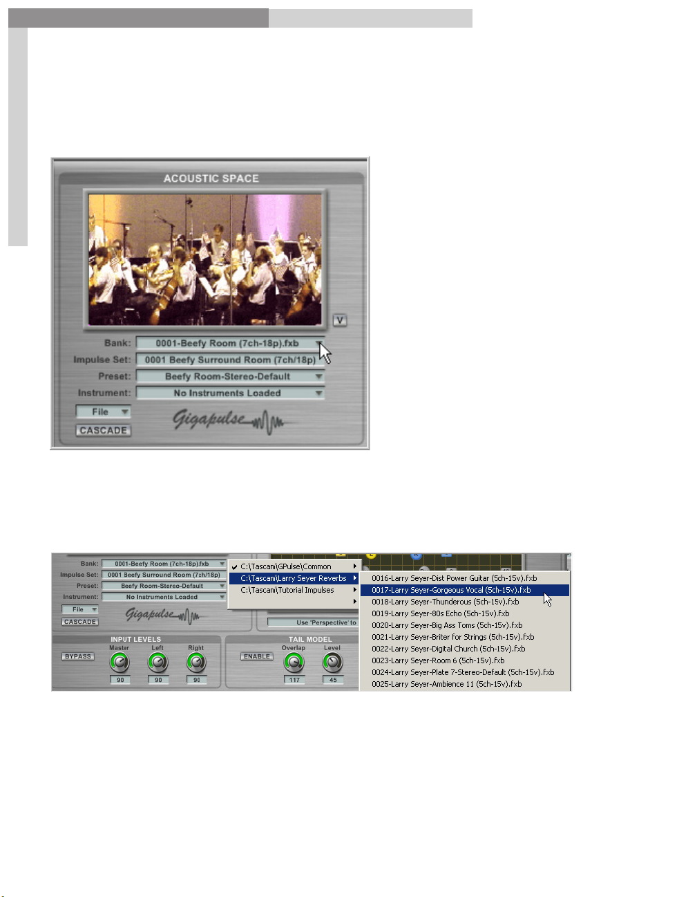
In Acoustic Space, select the desired environment from the Bank dropdown list.
3
The drop down menu labeled Bank will bring up a Directory/File list of different
recording spaces that are available on the system. Select the environment you want
from the list it gives. What shows up in this list is determined by the settings in the
ConfigurationWindow. (GigaPulse File Menu/Configuration)
Note that the checked items in the bank dropdown menus indicate the currently select
bank. If there are more than one check on a given menu cascade, then a single bank is
selected and can be found using each of the redundant search paths being display.
3
Page 4
GigaPulse™ User Guide
GigaPulse Quickstart
GigaPulse Quick Start
Enable Microphones:
To enable the other microphones, simply click on them with the mouse. Keep in mind
that each extra microphone uses extra CPU resources.
Alternatively, you can use the ‘ON” buttons in the Microphone Fader section to enable
and disable mics (see “Adjust Mic Levels”, below). For GigaPulseSP, this is the only way
to control microphone use.
4
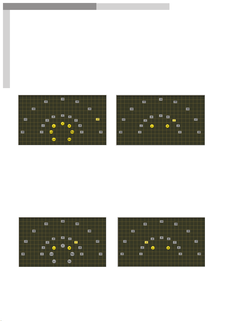
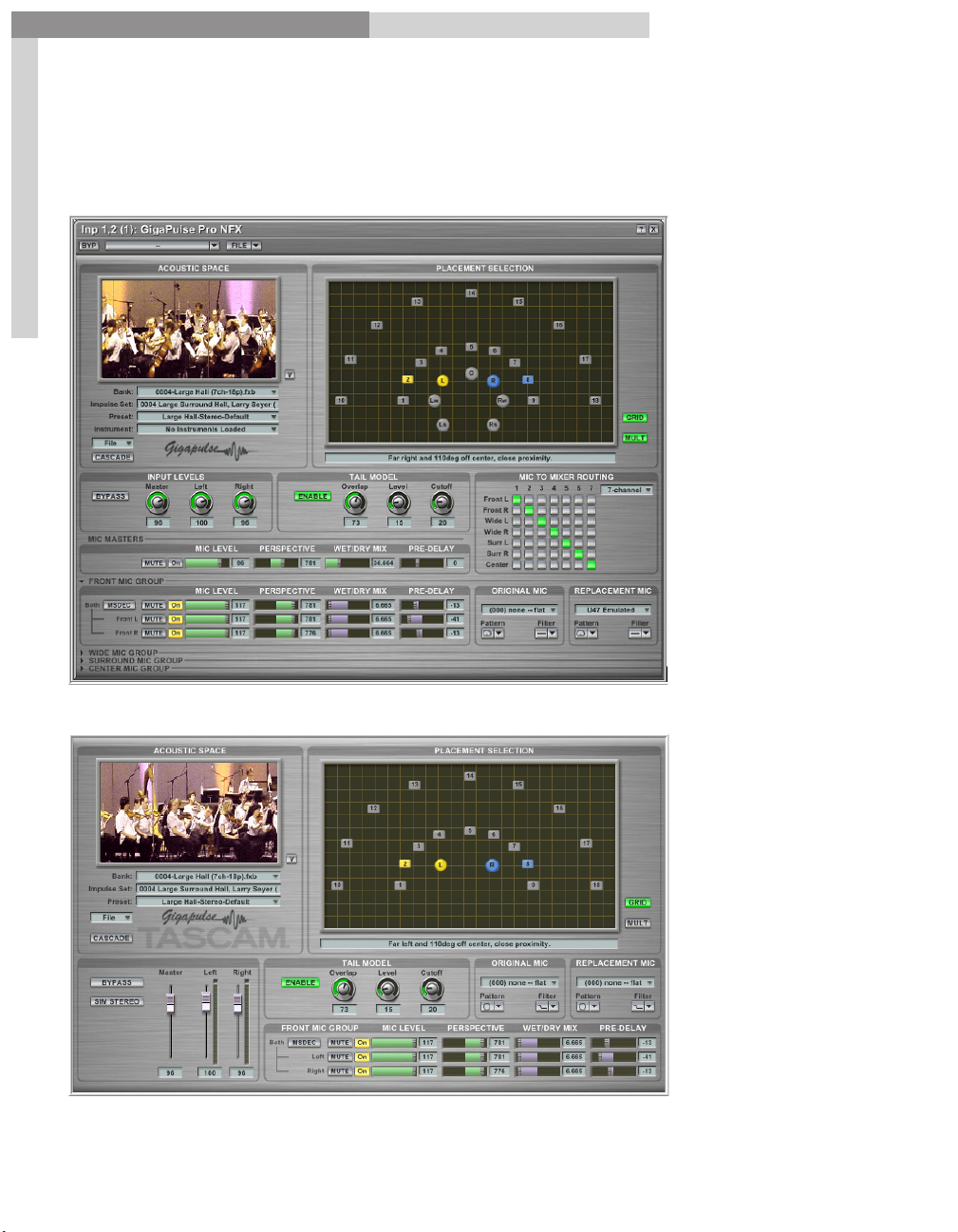
Fig A GigaPulse Pro Fig B GigaPulse VST
Select Stage Positions:
Point Source Method:
Click on any single stage position (square) with the mouse. All the enabled mics will
reference that one point for all the room characteristics. This is best for a single
instrument or very small group, and is very good for monaural sources. Try out several
positions while playing audio through the GigaPulse to hear the results.
Fig C GigaPulse Pro Fig D GigaPulse VST
4
Page 5
GigaPulse™ User Guide
GigaPulse Quickstart
GigaPulse Quick Start
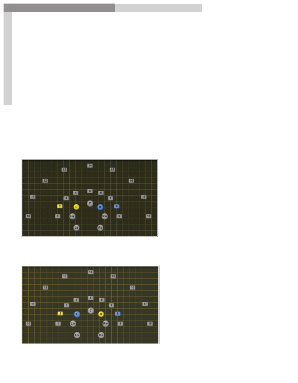
Multi-Placement Method:
Instead of referencing a single position on the stage, the Multi-Placement mode mic
selection allows specific microphones to be assigned directly to specific stage positions.
To do this, hold down the ctrl key and then click on a mic. Then select a stage position.
Repeat for the other mic positions that you want to assign.
Multi-Placement Mode can be used for a variety of effects.
5
Stereo spread across the stage spanning from any position to another. This would be
ideal for a string ensemble. It would effectively place an ensemble across the stage
and preserve the stereo image. Assigning and ensemble with the point source method
tends to decrease the stereo imaging. In fact, you can’t tell the difference between a
mono and stereo sample with the point source method.
Blend of multiple positions. You could have a stereo blend from a front left to a back
right position.
5
Page 6
GigaPulse™ User Guide
GigaPulse Quickstart
GigaPulse Quick Start
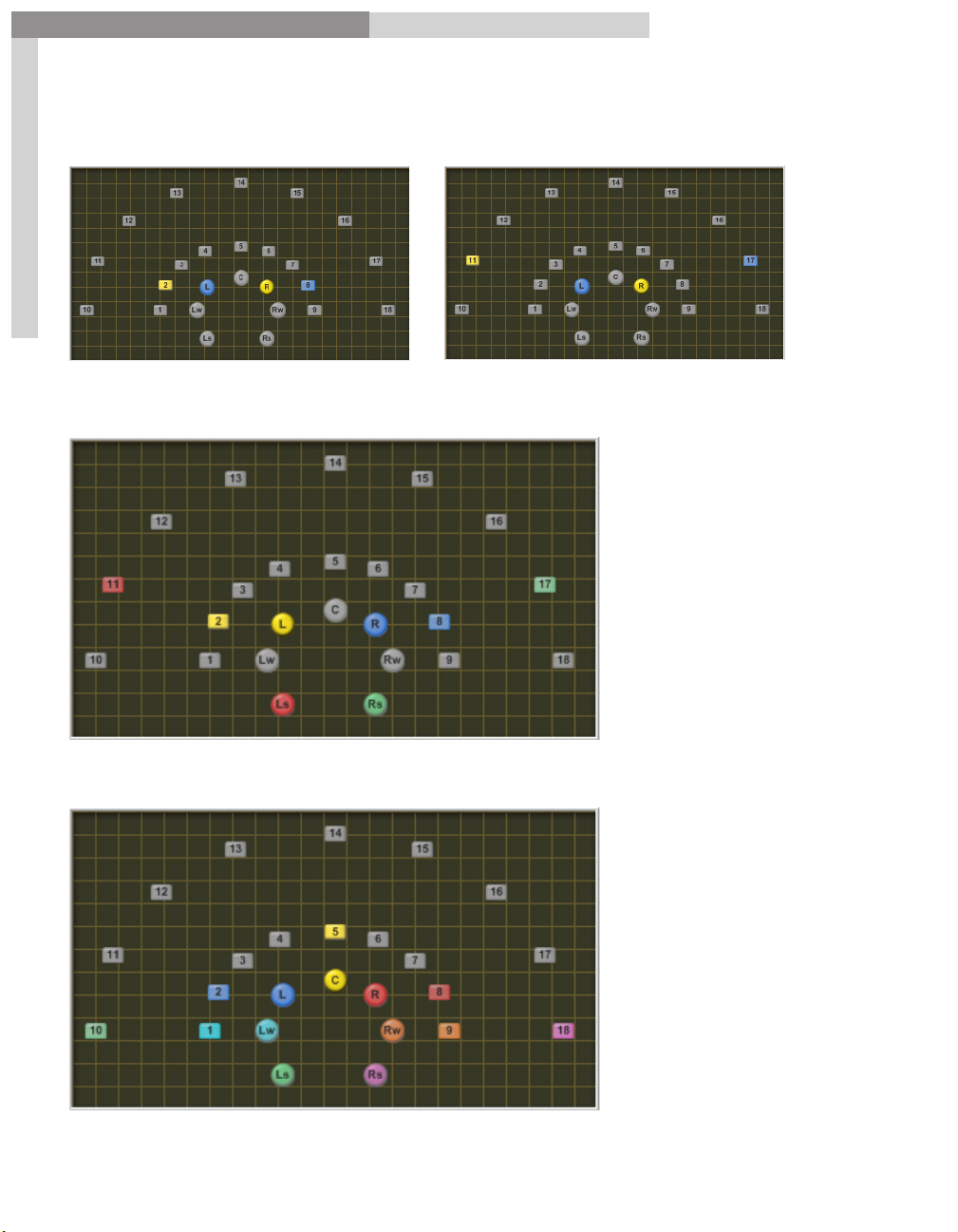
Reverse the stereo image by cross-assigning them.
6
Assign surround mics to far stage positions. You get more colors with addition
microphone assignments.
Assign each mic to a stage position.
6
Page 7
GigaPulse™ User Guide
GigaPulse Quickstart
Adjust Input Levels:
GigaPulse Quick Start
Use the
The
compare the original sound with what you are getting now.
Note: The Bypass button does not exist on the VST or SP versions.
Please use the Host’s Bypass control for this feature.
7
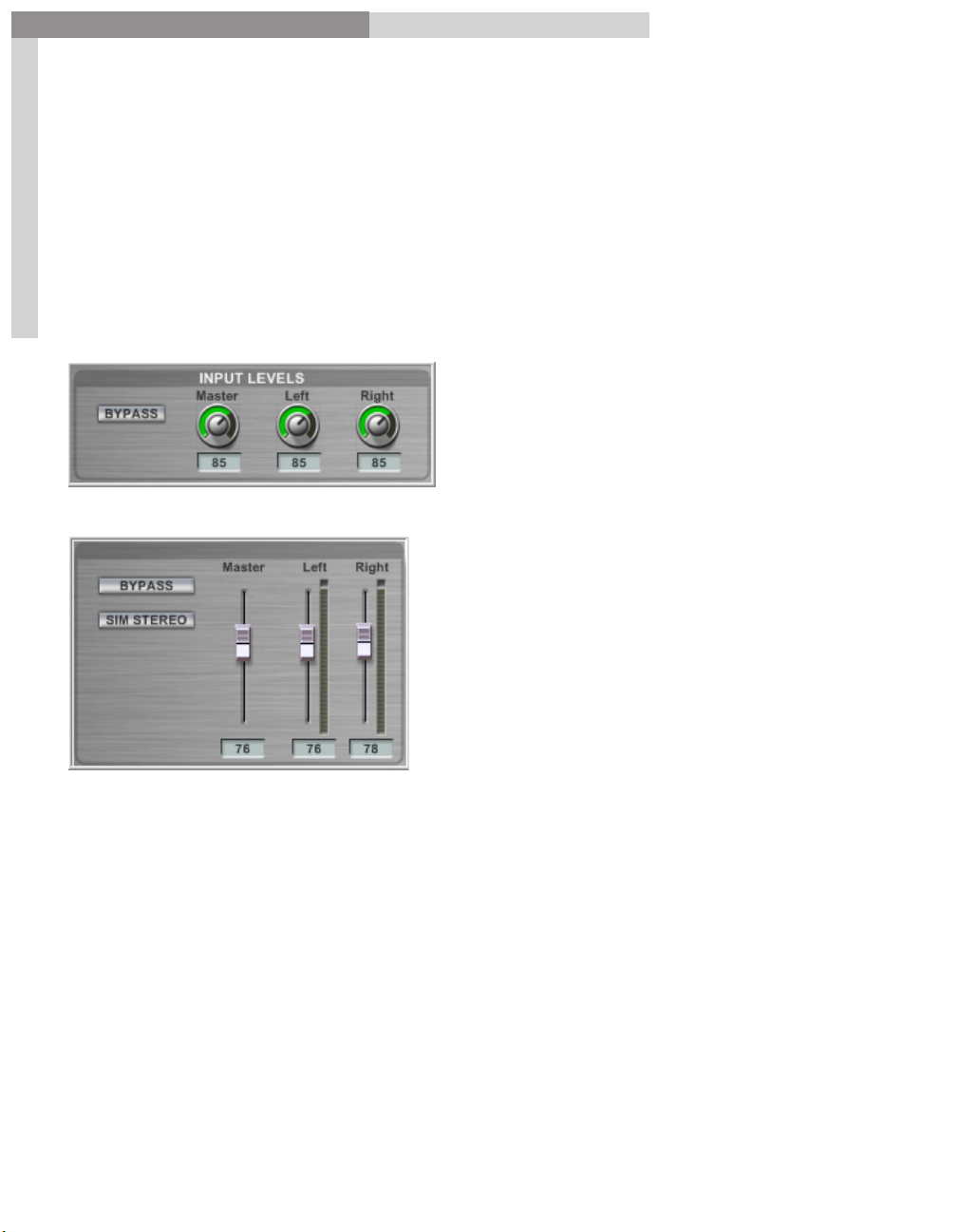
Input Levels
Bypass Button
to make your desired volume adjustments.
is useful here as it allows you to instantly bypass the GigaPulse to
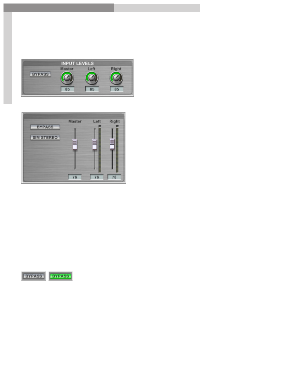
GigaPulse Pro Input Levels:
GigaPulse VST Input Levels:
There are separate controls for the Left, Right and Master input levels.
The Master level will adjust the Left and Right levels together while keeping them
relative to each other. Each slave control’s relative position is remembered even if the
master attempts to drive the slave past a maximum or minimum point.
Moving the individual Left or Right inputs will also adjust the Master input level by 50
percent. If you move one of the Left or Right knobs, the Master will be increased or
reduced by half that amount. (Showing the average between the two signals)
If the master is moves such that it forces one (but not both) of the faders to the
maximum or minimum, the Master will maintain the average of the two faders
trajectory (the position of the fader if it had NOT been limited by the maximum or
minimum). As such, a maximized slave fader will not move until the master has pulled
the slave’s trajectory below the maximum value.
7
Page 8
GigaPulse™ User Guide
GigaPulse Quickstart
Microphone Replacement:
GigaPulse Quick Start
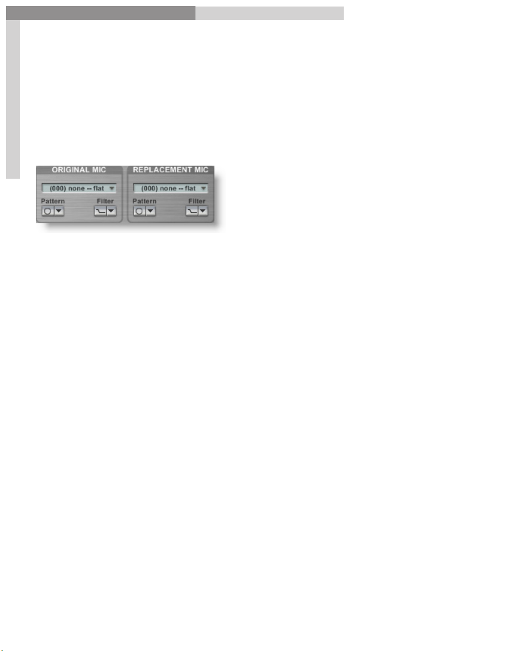
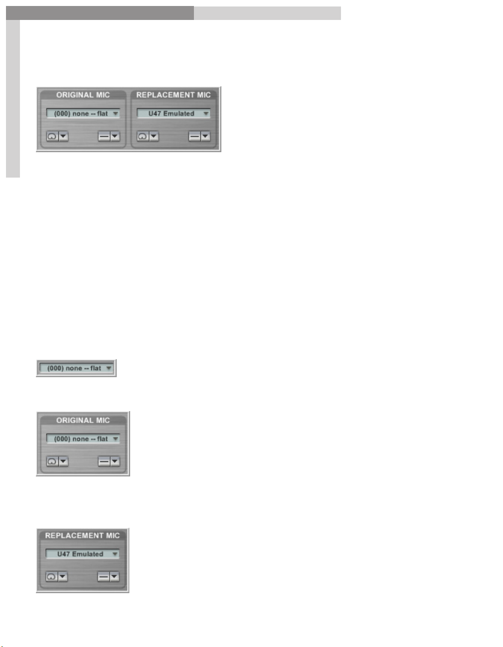
Mic Replacement
may be used to add or remove microphone characteristics.
Once an Original Mic is selected, this Mic’s characteristics will be removed from the
envirmonment.
Once a Replacment Mic is slected, the Mic’s characteristics will be added to the
enviroment.
8
This will be of value even to those who are not experienced recording engineers
who know a carotid mic* from a figure eight mic, because this is a chance to hear
& experiment with a range of different types, makes and models of mics without
spending a fortune.
In the drop down list in
sample if its known. If you do not know the model used, select
If the model used has more than one pattern, use the
Original Mic
, select the model of microphone used in the
000 none – flat.
Pattern
drop down list to make
the appropriate selection.
Filter
If the model and pattern has a filter as well, select as needed in the
drop down list.
Then choose a replacement mic from the “Replacement Mic” dropdown. The
characteristics of the new mic will affect the audio material very closely the way
the real microphone would. Be sure to check out any patterns and filters on the
replacement mic.
8
Page 9
GigaPulse™ User Guide
GigaPulse Quickstart
GigaPulse Quick Start
Adjust the Mic Levels:
GigaPulse VST Mic Master Pane: (Stereo)
9
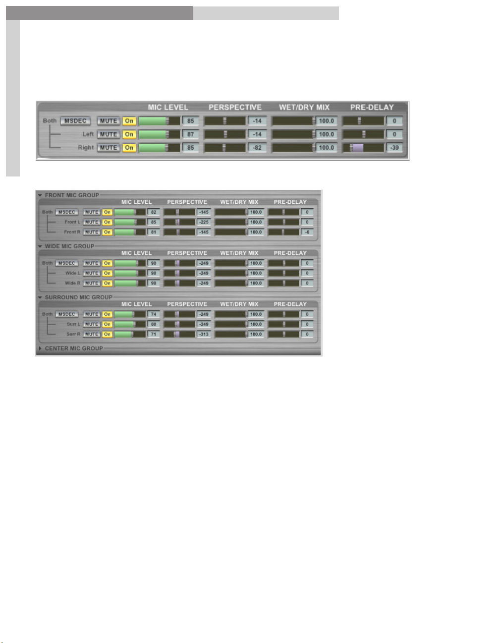
GigaPulse Pro Mic Master Pane: (Multi Channels)
MSDEC Button
recording mono-compatible stereo sound. This technique also offers custom control
of the stereo width and volume levels. A Figure-8 microphone (see the section on Mic
Replacement) is used with a second, uni-directional microphone to create a stereo
signal. MSDEC decodes the signal for stereo output
Mic Level
Perspective
Perspective is the relative distance of the performer to the microphone, and is
simulated by subtle variations of timing and resonance. Perspective is most often used
in rooms & halls to modify the front to back distance between stage positions.
Wet/Dry Mix
or individual mic channel. (Used when the impulses or banks are of an emulated
processor or reverb)
-MSDEC stands for Mid-Side DECoding, which is a handy method of
controls the output volume of the Master and the individual channels.
adjusts the relative perspective of the Master or individual mic channels.
adjusts the ratio (balance) of wet versus dry signal for the Master
9
Page 10

GigaPulse™ User Guide
GigaPulse Quickstart
GigaPulse Quick Start
Pre-Delay
nudges the impulse start point forward or backward in time. (Only adjust
this when no audio is passing through GigaPulse.)
ON
The
button of each mic is a redundant control to that found in the Placement
Selection portion of the UI.
MUTE
The
button of each mic simply silences the mic. Note that the mic is still utilizing
CPU and memory. To free up a mic’s resources, use the ON button to turn the mic OFF.
10
For GigaPulse SP and Pro there are 4 mic groups, typically Front, Wide, Surround, and
Center (although the impulse set designer may give these groups (and the mics within
them) alternative names. GigaPulse VST only has one mic group and defaults to the
front mic group of a given impulse set.
Note that each mic group has a Master and two slaves (only one slave and no master’s
for the center mic group). The master/slave controls work in the same way as the input
level controls. If a mic group is not displayed, it is because the mics within the group
have no impulses or have been disabled by the impulse set designer.
For GigaPulse Pro, there is also a Master Mic Group which controls the masters of the 4
individual mic groups.
10
Page 11
GigaPulse™ User Guide
GigaPulse Interface
GigaPulse Interface:
GigaPulse Pro (GigaStudio 3.0) Interface
11
GigaPulse Interface
GigaPulse VST Interface
11
Page 12

GigaPulse™ User Guide
GigaPulse Interface
GigaPulse Interface
The GigaPulse Main Interface breaks down very conveniently into several sections that
we will go over in detail in this chapter.
1. Acoustic Space
2. Placement Selection
3. Input Level
4. Tail Model
5. Microphone Replacement
6. Microphone Levels
12
12
Page 13
GigaPulse™ User Guide
GigaPulse Interface
GigaPulse Interface
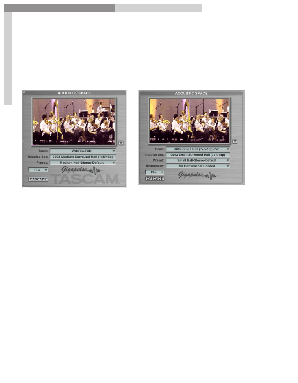
Acoustic Space:
The Acoustic Space section is where you load & save banks, presets as well as other file
management tasks. It also displays some very useful pictures of the environment that
is loaded.
GigaPulse VST GigaPulse Pro
13
Note: GigaPulse Pro has an additional menuany GigaStudio instrument that is assigned to the DSP channel that the GigaPulse is
assigned to.
The Acoustic Space section is further divided into several areas,
Instrument
. It displays the name of
A. Overall Graphics
B. Bank Menu
C. Impulse Set
D. Preset
E. File Menu
F. Cascade
13
Page 14
GigaPulse™ User Guide
GigaPulse Interface
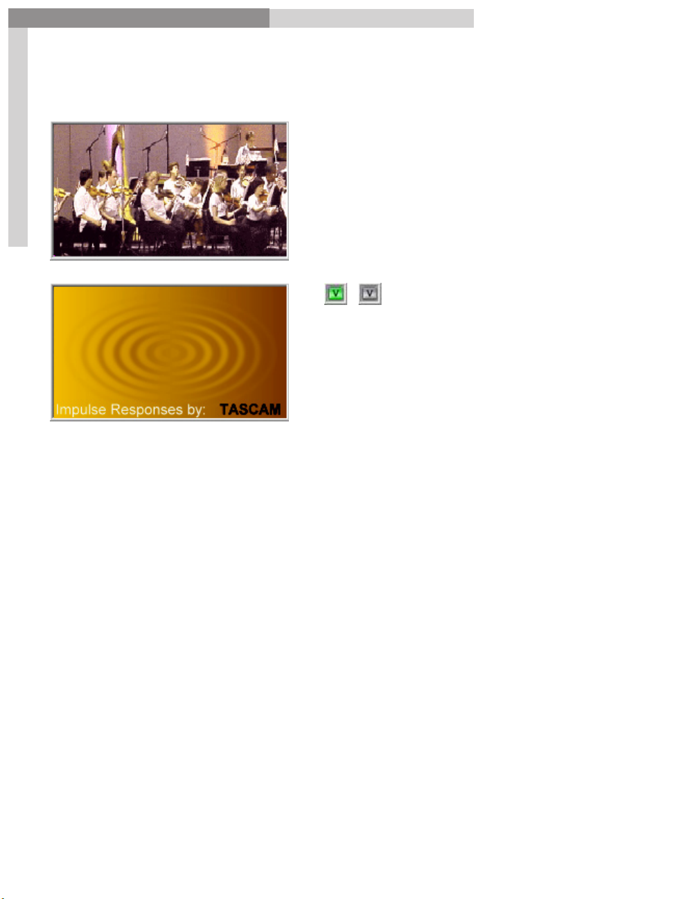
Acoustic Space-Overall Graphics:
14
GigaPulse Interface
The
Overall Graphics
show how the
recording space currently chosen might
look. In this case, it is a medium-sized
hall, and the direction of the view
depends upon which stage position is
selected in the placement selection pane.
Alternate View Button
The
changes the
graphic to an alternate picture. Quite
often this will be a credit for somebody,
perhaps the recording engineer or
information about the impulse library.
It can also be relevant information for using the impulse set.
Note: You can also toggle the view by simply clicking on the picture itself.
14
Page 15
GigaPulse™ User Guide
GigaPulse Interface
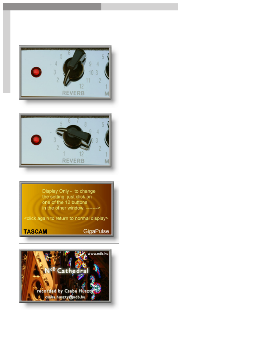
Acoustic Space-Overall Graphics-Examples:
15
GigaPulse Interface
Here is the graphic for the Tweed
Amp impulse bank. Here it shows
the reverb level set to 1.
If you change the reverb setting in
the placement selection pane by
selecting #4, the graphic updates as
well.
If you select the Alternate View
Button or click on the graphic you get
this window.
It is letting you know to click again to
get back to the other graphic.
Here is another example of an
Alternate View. This gives the credit
& contact information for the Csaba
Huszty Notre Dame de Budepest
Cathedral impulse set.
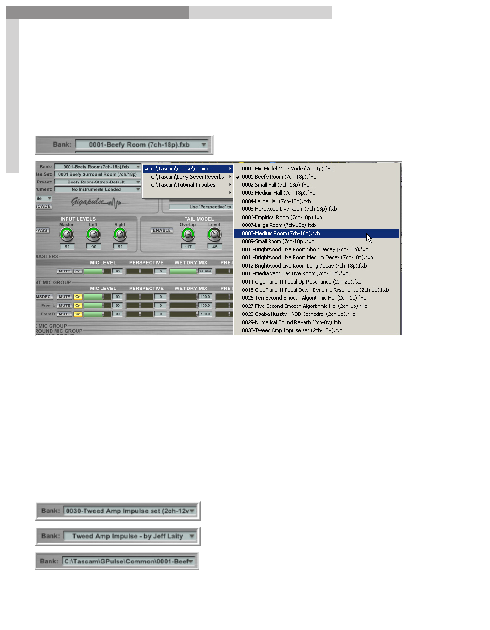
Acoustic Space-Bank Menu:
15
Page 16
GigaPulse™ User Guide
GigaPulse Interface
GigaPulse Interface
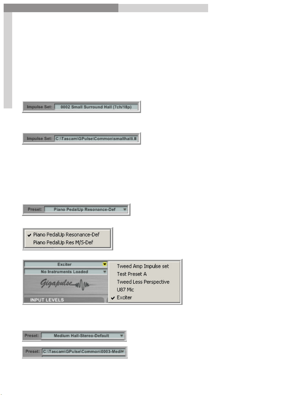
Acoustic Space-Bank Menu:
The
Bank Menu
Banks. (All the folders that are enabled in the Configuration Window. These can be
enabled & disabled to customize & simplify this menu)
16
brings up a Folder/File dropdown list of all the available GigaPulse
(Click the triangle at the right of the text to open the Bank Folder/File dropdown
menus. Checked items indicate currently selected Banks)
Included with the GigaPulse program are small, intimate rooms, medium rooms, and
large, resonant halls. There are selections designed for specific instruments, such as
guitar or drums, and even a couple of choices that are the actual space inside the
GigaPiano! (Kawai Soundboard resonance model)
There is also a 40-bank collection from C.K.S.D.E (See www.cksde.com for more details)
Note that [ctrl]+clicking on the Bank Menu will toggle between three different name
displays. The internal name, the file name and the location path.
16
Page 17
GigaPulse™ User Guide
GigaPulse Interface
Acoustic Space-Impulse Set menu:
GigaPulse Interface
Immediately below the Bank Menu is the
that is currently used. (Different Banks can share a single impulse set) Clicking on
the Impulse Set menu will toggle between two views. This menu is for display and is
dependent on which bank is loaded up.
Impulse Set
, which displays the impulse set
One [ctrl]+click displays the name of the impulse set.
17
Another [ctrl]+click displays the file path of the impulse set.
Acoustic Space-Preset Menu:
The Preset Menu gives a choice of available presets within the Bank. A preset includes
all the adjustable settings in the GigaPulse interface. You can save your own custom
presets at any time using the File Menu.
Here is the Preset Menu.
Clicking on the Preset Menu displays all the
available presets that are part of the current Bank.
(The current preset is checked)
Here is an example
of several custom
created presets.
(The current preset
is checked)
[Ctrl]+Clicking will toggle the display between the preset name and the file path of the
bank.
Note: You may select presets from
the bank menu if the ‘Show Presets’
check box is check in the GigaPulse
Configuration panel.
17
Page 18
GigaPulse™ User Guide
GigaPulse Interface
GigaPulse Interface
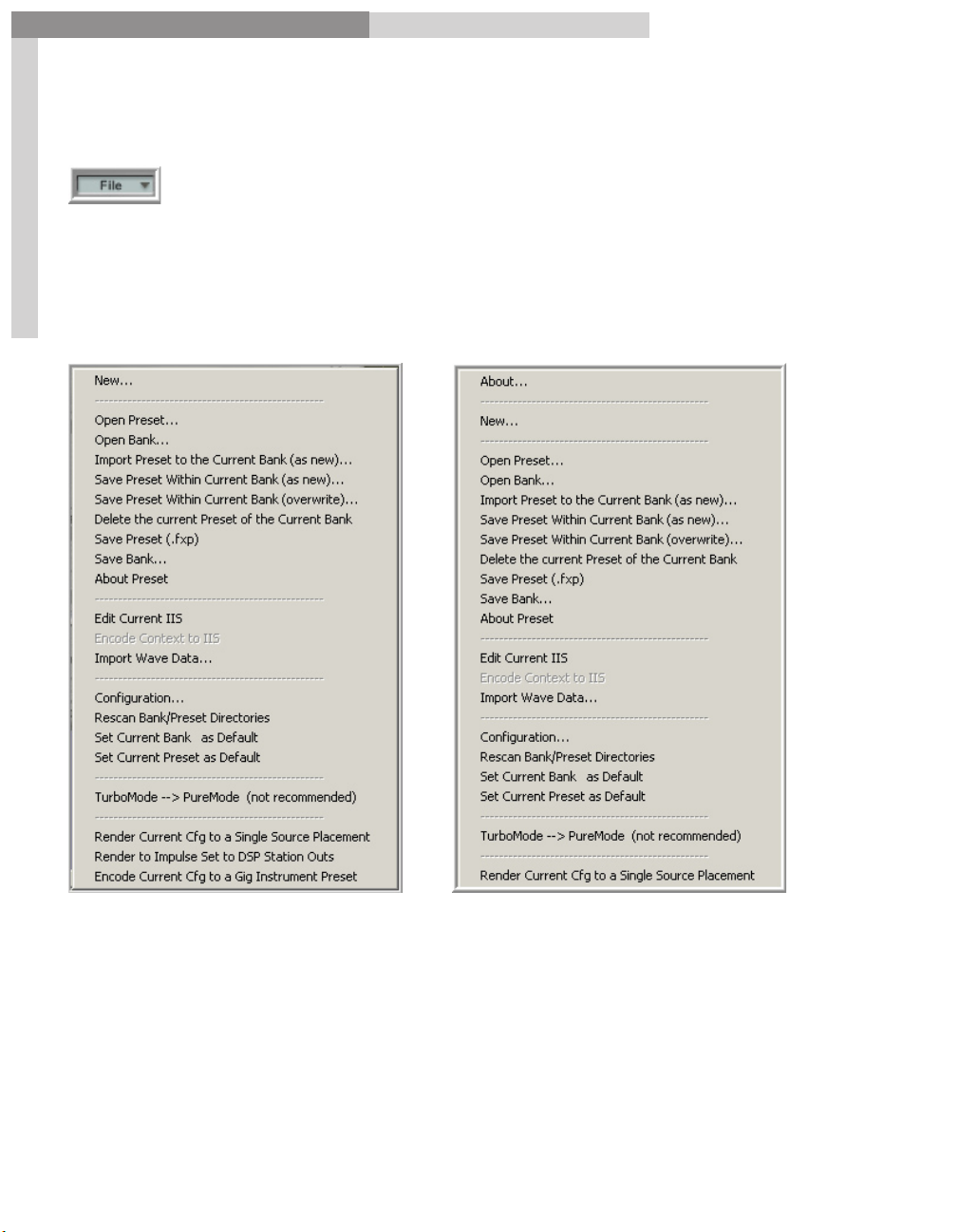
Acoustic Space-File Menu:
The
File Menu
Windows-based programs. This is where all the file management & GigaPulse
Configuration settings are found.
18
GigaPulse Pro File Menu
opens a set of options rather like the file button on many other
GigaPulse VST File Menu
Notice that there are 3 menu item differences between the GigaPulse Pro and the
GigaPulse VST File Menus.
1. “Render to Impulse Set to DSP Station Outs” is GigaStudio Specific and not
needed in GigaPulse VST.
2. “Encode Current Cfg to a Giga Instrument Preset” is GigaStudio Specific and
not needed in GigaPulse VST.
3. “About” is included in GigaPulse VST only. For GigaPulse Pro, the “About”
window is accessed in the main interface of GigaStudio.
18
Page 19

GigaPulse™ User Guide
GigaPulse Interface
GigaPulse Interface
Acoustic Space: Cascade Button
The Cascade Button combines the benefits, settings & impulse sets of two different
banks while using the CPU resources of only one. You get two for the price of one using
this feature. A room impulse uses plenty of CPU resources as it is. Imagine you also
want to add a Violin Body or Piano Resonance to the mix. Normally doing so would
require two separate instances of GigaPulse to be loaded and thus twice the CPU load.
However, Cascade Mode resolves the problem by combining two or more impulse sets.
19
The only limitation with the Cascade feature is that you lose access to the settings of
the first GigaPulse banks once you have clicked on the cascade button. You can tweak
the second one after cascading but not the first one.
To use the cascade mode of GigaPulse to Combine two ImpulseSets:
For example, you can apply a ConcertHall as well as a PianoBody to a dry piano.
1. Select a Bank to load the first ImpulseSet (i.e.ConcertHall) and adjust the controls to
your liking.
2. Click on the ‘Cascade’ button to turn it on (the yellow ‘on’ light should appear in the
‘Cascade’ button).
3. Select a Bank to load the second ImpulseSet (i.e. PianoBody).
At this time, the latest impulse set that is loaded (i.e. PianoBody) is combined with
the first (ConcertHall) sound created in step (1). As you play notes, you will hear
attributes of each…as if your instrument is being played in the (PianoBody) within the
(ConcertHall).
Note that the ‘Cascade’ button’s ‘On’ light remains in the ‘On’ state. This indicates that
GigaPulse remains in ‘Cascade Mode’ (cascading the first impulse set (ConcertHall) with
the current ImpulseSet and settings).
If desired, you may encode this cascaded GigaPulse configuration to a Gig File using the
‘File’ menu’s ‘Encode Current Cfg to a Gig Instrument’.
4. Repeat Step 3 as often as desired.
For example: Load a different ImpulseSet (i.e. GuitarBody).
At this time, the latest impulse set that is loaded (i.e. GuitarBody) is combined with
the first (ConcertHall). As you play notes, you will hear attributes of each…as if
your instrument is being played in the (GuitarBody) within the (ConcertHall). The
(PianoBody) impulse set is no longer applied…it was replaced by the (GuitarBody).
19
Page 20

GigaPulse™ User Guide
GigaPulse Interface
5. To disable ‘Cascade Mode’, simple click the ‘Cascade’ button again and the ‘On’ light
will turn off. This indicates that ‘Cascade Mode’ has been disabled.
At this time, all preserved cascade states are removed. You will only hear your
instrument’s notes being played through the current GigaPulse configuration.
GigaPulse Interface
To use the cascade mode of GigaPulse to Combine more than two
ImpulseSets:
20
For example, you might want to remove an OriginalPianoBody from a normal piano
GigInstrument, then apply a ConcertHall as well as a ReplacementPianoBody.
1. Load the first ImpulseSet Preset (i.e. ConcertHall).
2. Click on the ‘Cascade’ button to turn it on (the yellow ‘on’ light should appear in the
‘Cascade’ button).
3. Load the second ImpulseSet Preset (i.e. InverseOriginalPianoBody, to remove the
piano body).
As before, the latest impulse set that is loaded (i.e. InverseOriginalPianoBody) is
combined with the first (ConcertHall). As you play notes,you will hear attributes of
each…as if your instrument is being played without the (OriginalPianoBody) within the
(ConcertHall).
You may continue to tweak the controls and change banks/presets. As long as the
‘Cascade’ button light remains on, your current GigaPulse configuration is being
cascaded with the GigaPulse configuration preserved in steps (1) and (2).
4. To apply another cascaded impulse set, use the Super Cascade Mode. Hold down the
control key and click on the ‘Cascade’ button (Ctrl-Cascade).
Note that the ‘Cascade’ button light goes off momentarily. When it comes back on, your
current state (steps 1-4) is preserved as a combined model (ReplacementPianoBody+Co
ncertHall). You are again in normal ‘Cascade’ mode, ready to bring in your third impulse
set (ReplacementPianoBody).
20
Page 21

GigaPulse™ User Guide
GigaPulse Interface
GigaPulse Interface
5. Load a third ImpulseSet (i.e. ReplacementPianoBody).
At this time, the latest impulse set that is loaded (i.e. ReplacementPianoBody) is
combined with the preserved model (ReplacementPianoBody+ConcertHall). As you
play notes, you will hear attributes of each…as if your instrument is being played with
the (OriginalPianoBody) removed, the (ReplacementPianoBody) added, and within the
(ConcertHall).
You may continue to tweak the controls and change banks/presets. As long as the
21
‘Cascade’ button light remains on, your current GigaPulse configuration is being
cascaded with the GigaPulse configuration preserved in steps (1) thru (4).
If desired, you may encode this cascaded GigaPulse configuration to a Gig File using the
‘File’ menu’s ‘Encode Current Cfg to a Gig Instrument’.
6. Repeat steps 4-5 as often as required for your needs.
7. Turn off ‘Cascade Mode’ by clicking on the ‘Cascade’ button.
At this time, all preserved cascade states are removed. You will only hear your
instrument’s notes being played through the current GigaPulse configuration.
21
Page 22
GigaPulse™ User Guide
GigaPulse Interface
GigaPulse Interface
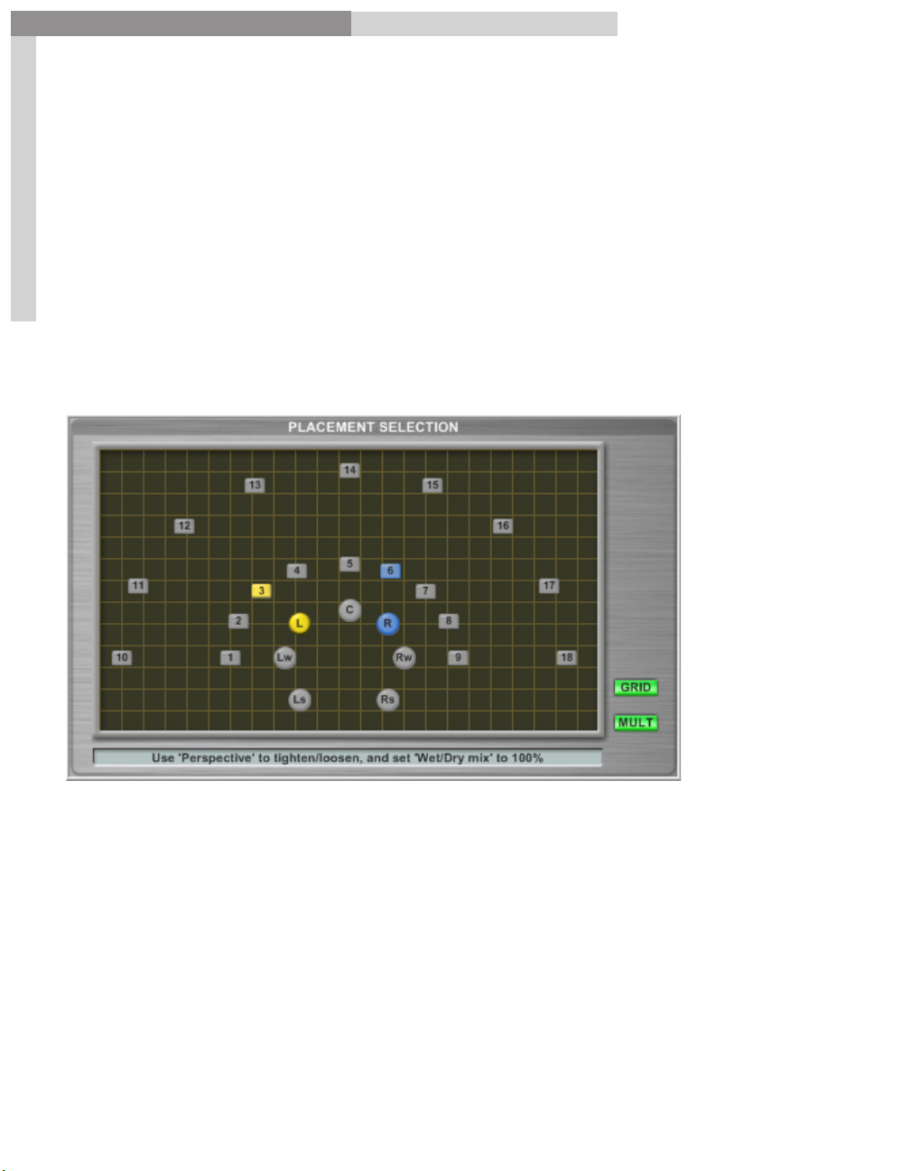
PLACEMENT SELECTION:
Note: Not available in GigaPulse SP.
Having the performance and the performance space are only two parts of the recording
equation; microphones are still required. Using Placement Selection, you can control
the mics and their relationship to a variety of stage or environment positions
22
Halls & Room Environments:
For Halls & Rooms, the Placement Selection pane shows placement of the mics – round
markers – and up to 18-labeled square stage or environment position markers.
The stage position markers show where the Impulse Responses were measured in the
real world when the impulses were created. This will permit you to move different
instruments around the stage, whether right or left, or closer or farther away.
22
Page 23
GigaPulse™ User Guide
GigaPulse Interface
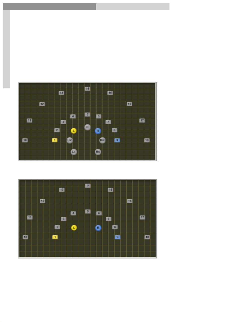
Note: GigaPulse VST is a stereo plug-in. For the rooms & halls, the left and right front
microphones will be the only ones accessible. GigaPulse VST will ignore the other mic
positions even though these impulses are included.
Note: In the near future, a patch update will be made available that will make these
extra microphone positions available.
GigaPulse Interface
GigaPulse Pro Placement Selection (Rooms & Halls)
23
GigaPulse VST Placement Selection (Rooms & Halls)
23
Page 24
GigaPulse™ User Guide
GigaPulse Interface
GigaPulse Interface
Other Environments:
Another way the Placement Selection window is used is to represent instruments,
audio gear or alternative microphone positions.
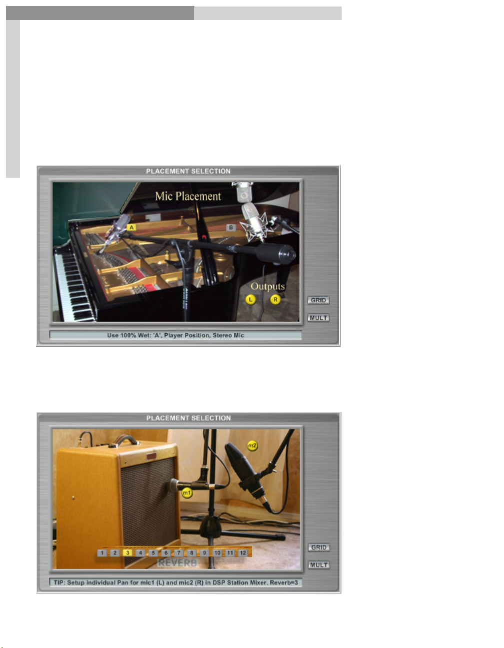
Here we have the Acoustic Piano Mic Placement. You can choose between the primary
microphone position near the piano soundboard (A) – Player Perspective – or the
Mid-Side placement off to the side (B) – Audience Perspective.
24
In this example, we have the Tweed Guitar Amplifier Placement.
Here we can choose either or both of the microphones and any of 12 amp reverb
settings. Each Microphone can also be assigned an individual reverb setting. Again, the
picture orients you to the actual environment.
24
Page 25
GigaPulse™ User Guide
GigaPulse Interface
GigaPulse Interface
Here we have a representation of a piece of audio hardware. This could easily be a black
screen with grid markers and buttons and still work the same. However the picture is a
helpful cue to what kind of environment we are dealing with.
(Audio Gear as opposed to a Room)
25
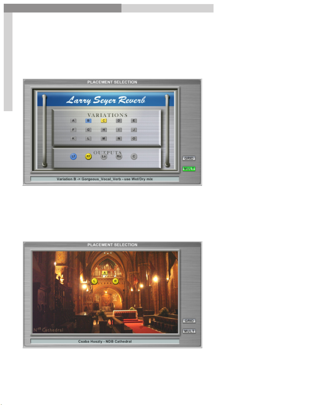
This last example of the Placement Selection window is purely for display and
reference. There are no positions or microphones to select. (This being a single stereo
impulse with one position) In this case, the graphic simply shows you what the
environment actually looks like.
Player Perspective
is the “Organ” (A)
Microphone
Perspective
positions were
hung from the
ceiling towards the
center of the room.
25
Page 26
GigaPulse™ User Guide
GigaPulse Interface
GigaPulse Interface
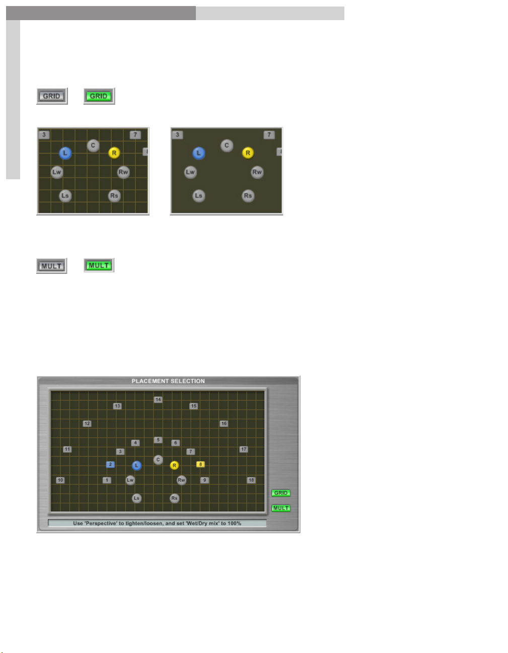
Grid Button:
The
Grid Button
on and off. The button is lighted green when Grid is on.
Grid On
26
turns the grid pattern in the Placement Selection
Grid Off
Multi-Placement Selection Mode Button:
The
Multi-Placement Selection Mode Button
function. This button is lighted green when Multi-Selection is enabled.
enables & disables the Multi-Selection
Multi-Selection is automatically enabled when you hold down Ctrl-Select while
selecting a mic and then a position button. This will cause the Multi Button to light up.
Clicking on the button at this point will disable all the multiple selections.
In this example, the L mic is recording the performance (audio stream) from position 2
while the R mic is recording the performance of position 8.
Multiple Selections allow specific mics to be directly assigned to specific positions or
room locations.
26
Page 27
GigaPulse™ User Guide
GigaPulse Interface
GigaPulse Interface
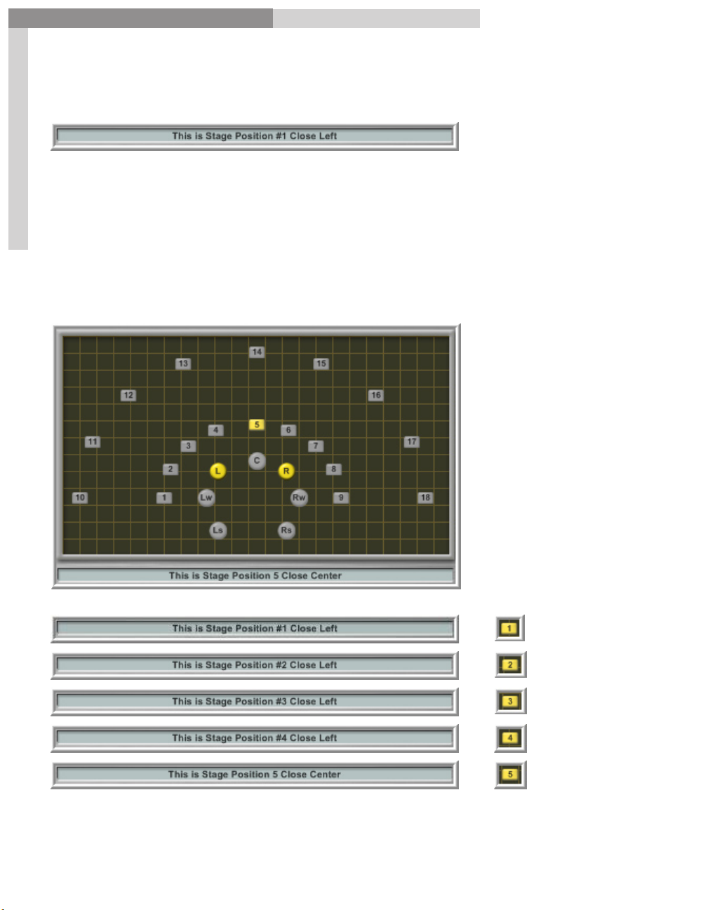
Description Field:
The
Description Field
information about the selected position. Each of up to 18 positions can have its own
distinct Description Field.
27
In some cases there can be further information concerning how to best apply the
preset in a musical context. Clicking on the field will also toggle between the Current
Placement Image and the Overall Screen Images.
gives information regarding the preset or even specific
27
Page 28
GigaPulse™ User Guide
GigaPulse Interface
INPUT LEVEL:
GigaPulse Pro Input Levels:
28
GigaPulse VST Input Levels:
GigaPulse Interface
The input levels adjust the amount of signal that passes through GigaPulse.
You can adjust the left and right signal levels independently or set them both at once
using the master input knob. (or slider in GigaPulse VST) If the master is moves such
that it forces one (but not both) of the faders to the maximum or minimum, the Master
will maintain the average of the two faders trajectory (the position of the fader if it had
NOT been limited by the maximum or minimum). As such, a maximized slave fader will
not move until the master has pulled the slave’s trajectory below the maximum value.
Bypass:
Use the Bypass Button to quickly enable or disable the GigaPulse effect. When enabled,
the button will be lit up green.
Note: The Bypass button does not exist on the VST or SP versions. Please use the Host’s
Bypass control for this feature.
28
Page 29
GigaPulse™ User Guide
GigaPulse Interface
GigaPulse Interface
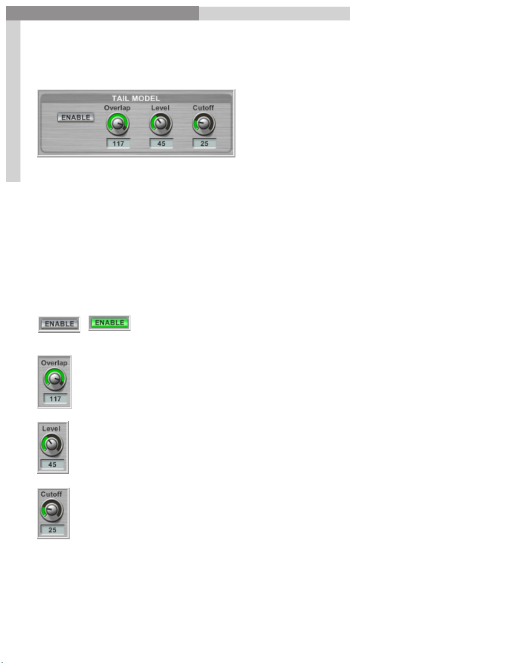
Tail Model:
The user may override enable/disable of the tail extention (for impulses sets over 3
29
seconds in length) by clicking on this button. Note that when a new bank selection is
made, the user override will be cancelled and the impulse set’s default will be set.
The Tail Model is used when dealing with impulses that are longer than 3 seconds.
(48khz 131072 samples to be exact). After 3 seconds, the Tail Model will smoothly blend
an algorithm reverb tail near the 3-second cutoff into the digital reverb. This can save a
lot of CPU resources with virtually no noticeable change in audio. (This tail will ideally
kick in at very low levels as the reverb is trailing off) If the impulse environment is less
than 3 seconds, the Tail Model will not be enabled, and enabling it will have no effect.
Overlap Control
Enable Button
– Has a minimum/maximum range of 0-127. This is a
– When lighted green, the Tail Model is on.
timing offset combined with a cross fade that adjusts the overlap between
the convolution signal and the artificial tail.
Level Control
– The level control allows the Tail Model signal level to be
adjusted to better match the original signal.
Cutoff Control
– The cutoff control is essentially a low pass filter.
It permits the tonal quality of the Tail Model signal to be matched to that of
the original signal.
29
Page 30
GigaPulse™ User Guide
GigaPulse Interface
GigaPulse Interface
MIC REPLACEMENT:
Different microphones have different recording characteristics. Microphones come
30
in different quality levels (price will be a clue), and they also have different directional
characteristics (Omni directional, Cardoid, Wide Cardoid, Hyper Cardoid, Figure 8), They
may also give different responses according to the pitch or timbre of the source audio.
To cover all these possibilities, GigaPulse includes a generous selection of Microphone
impulse models. You can use these to remove the characteristics of one microphone
and replace it with the characteristics of another. Note: Processor impulses may also be
used here. “E.G. Boxinator”
Note that using original (inverse) and/or replacement mics (as well as Pattern and Filter
selections) will cause GigaPulse to run pause and run a short calculation when the mic
models are chosen, but they do not require additional CPU when processing audio.
Drop Down Menus:
GigaPulse gives you a generous choice of microphones. Choose
these using the Drop Down Menus.
Original Mic:
Provides a list of microphones that might have been used in
the original recording that is being processed by GigaPulse.
By selecting the appropriate mic, you apply the inverse
impulse response, which effectively removes its character of
the selected mic model from the original audio.
(This is why we have the (inv) at the beginning of the majority of choices.)
Replacement Mic:
Provides a similar list, but these microphones are used to
replace the original one.
30
Page 31

GigaPulse™ User Guide
GigaPulse Interface
GigaPulse Interface
One thing is important to understand here, that the match with the microphones used
may not be absolutely perfect. The characteristics employed by GigaPulse are those of
good condition, unmodified models,and there may be variations according to age and
wear. The match should be fairly close in most cases though.
31
31
Page 32

GigaPulse™ User Guide
GigaPulse Interface
Microphone Lists:
32
GigaPulse Interface
32
Page 33

GigaPulse™ User Guide
GigaPulse Interface
Here is a breakdown of the Microphone Replacement List
33
GigaPulse Interface
33
Page 34

GigaPulse™ User Guide
GigaPulse Interface
GigaPulse Interface
Pattern Button:
Most microphones have a choice of polarity patterns. Some have just one pattern while
others have up to 5 patterns. Click on the Pattern Button dropdown to see what is
available for each mic.
34
Omni
– Short for Omnidirectional, this type of microphone records
fairly evenly from any direction around it. This the most basic form of
microphone; all other forms are modifications of the Omni.
Cardoid
recording pattern resembles a heart, hence the name (Cardio-).
Figure-8
performers while bypassing everything off axis. The Figure 8 pattern is also
used to creating mono compatible Mid-Side recordings.
– This is a unidirectional microphone; a graphic representation of its
Variations include
– This is a bi-directional microphone, often used to record two
Wide Cardoid
and
Hyper Cardoid.
Note: These pattern symbols are representations of what a microphone dB & frequency
pattern looks like when charted out on paper.
Filter Button:
The type of microphone roll-off is selected here. Many mics have only the flat rolloff
setting but others can have one or more. The roll-off filters out all the frequencies
below the roll-off frequency. The roll-off is often used to reduce the excess low-end
sound of a bass instrument or the boominess in a close proximity vocal recording.
-Functionality of roll-off
34
Page 35

GigaPulse™ User Guide
GigaPulse Interface
GigaPulse Interface
Mic Masters & Groups:
Finally, we have the controls for master and individual microphone groups.
35
The default control of all the Mic Group settings is matched by the master settings. If
the individual settings are adjusted individually, the masters control them by keeping
their settings relative to one another.
(Proportional Relationship)
Note: The Center channel has only one mic in its group.
Front Mic Group Center Mic Group
Wide Mic Group Surround Mic group
35
Page 36

GigaPulse™ User Guide
GigaPulse Interface
GigaPulse Interface
Mid-Side Decode Button: (MSDEC)
MSDEC stands for Mid-Side DECoding, which is a handy method of recording monocompatible stereo sound. This technique also offers custom control of the stereo width
and volume levels. A Figure-8 microphone (see the section on Mic Replacement) is used
with a second, uni-directional microphone to create a stereo signal. MSDEC decodes the
signal for stereo output. The button will be green when enabled.
36
Here is a picture of a Mid-Side
Microphone arrangement as used with
the GigaPiano II GigaPulse Bank.
Mute Button:
Silences the Master or the individual channel, but still uses CPU. The button is yellow
when the signal is muted.
On Button:
The On button turns off the individual microphones and frees up the CPU resources.
The mics can also be enabled & disabled by clicking on them in the Placement Selection
window. When a mic is enabled, it will be highlighted in the Placement Selection
window and its “On” button will be lit yellow. (And vice versa when disabled)
Examples:
Front Mics “On” Center Mic “On”
36
Page 37

GigaPulse™ User Guide
GigaPulse Interface
GigaPulse Interface
Mic Level:
Adjusts the volume of the Master or individual mic channel.
Mic Level Readout:
Shows the volume of the Master or individual channel on a scale of 0-127.
37
Perspective Control:
Adjusts the relative perspective of the Master or individual mic channels. Perspective
is the relative distance of the performer to the microphone, and is simulated by subtle
variations of timing and resonance. Perspective is most often used in rooms & halls to
modify the front to back distance between stage positions.
Perspective Readout:
Shows the relative perspective of the Master or individual channel on a scale of –1024
- 1023, with 0 usually being the point where the impulse response was sampled.
Wet/Dry Mix:
Adjusts the ratio (balance) of wet versus dry signal for the Master or individual mic
channel. (Used most when an impulse bank is of a processor. For example, the Larry
Seyer “Gorgeous Vocal Reverb”)
Wet/Dry Mix Readout:
Shows the ratio (balance) of wet versus dry signal for the Master or individual channel
as a percentage.
37
Page 38

GigaPulse™ User Guide
GigaPulse Interface
GigaPulse Interface
Pre-Delay:
Adjusting the Pre-Delay nudges the impulse start point forward or backward in time.
Pre-Delay Readout:
Displays the Pre-Delay settings on a scale of –64-63 (Sample start nudge by how many
38
samples forward or backward)
38
Page 39

GigaPulse™ User Guide
GigaPulse Interface
Mic to Mixer Routing: (GigaPulse Pro Only)
39
GigaPulse Interface
Sim Stereo
– Simulates a stereo signal from a mono source audio stream passing
through GigaPulse.
Width and Image Controls
Width Control
Image Control
– Simulates the width of the performing group from left to right.
– Simulates the depth of the performing group from front to back by
–These work as together when simulating stereo.
creating extra voices and shifting them slightly temporally.
Note:
Mic Names can be modified by the impulse set designer.
Disabled mics will not be displayed.
Unavailable channels will not be displayed.
39
Page 40

GigaPulse™ User Guide
GigaPulse Interface
GigaPulse VST:
The “Sim Stereo” button for GigaPulse VST is found in the master volume section. The
controls work the same in both programs.
GigaPulse Interface
Sim Stereo “Disabled”
40
Sim Stereo “Enabled”
40
Page 41

GigaPulse™ User Guide
GigaPulse File Menu
GigaPulse File Menu
File Menu:
The File Menu opens a set of options rather like the file button on many other
Windows-based programs. This is where all the file management & GigaPulse
Configuration settings are found.
41
GigaPulse Pro File Menu GigaPulse VST File Menu
41
Page 42

GigaPulse™ User Guide
GigaPulse File Menu
About: GigaPulse VST Only
42
GigaPulse File Menu
This brings up the information screen.
In addition to some trademark, version
and copyright information, licensing and
registration information can be found
here.
Note: For GigaPulse pro, the “About” window is launched from the main GigaStudio
Help menu. That will launch the “About Gigastudio” window.
42
Page 43

GigaPulse™ User Guide
GigaPulse File Menu
GigaPulse File Menu
File Menu-New:
The
New
command brings up the GigaPulse Impulse Set Creator. This is where you start
out when you want to create a custom .IIS file from scratch.
(An IIS file is A collection of impulses defining a bank. Also known as an Instrument
Impulse Set. It includes all the impulses, text info and graphics)
The GigaPulse Impulse Set Creator Window:
43
43
Page 44

GigaPulse™ User Guide
GigaPulse File Menu
GigaPulse File Menu
File Menu-Open Preset
Presets contain most of the settings of the GigaPulse interface. This command allows
you to load an existing preset from the hard drive into the current loaded bank. It also
clears out any current presets and replaces them with the new one.
Select
Open Preset
44
Browse for a Preset and select it.
with the mouse:
This preset now becomes the
This example Preset Changes the microphone to a U87.
It also changes the Perspective sliders to a closer mic to performer
sounding setting.
44
Default Preset
Page 45

GigaPulse™ User Guide
GigaPulse File Menu
GigaPulse File Menu
Open Bank:
This opens an existing bank from the hard drive.
This does the same thing as the bank menu as shown here.
45
However, the Open Bank command allows you to browse the hard drive and load from
any folder on the system, including folders that the GigaPulse is not yet configured to
see.
Note that you can use the ‘Files ofType’ dropdown menu to search for and load .FXB
(bank files),.FXP (Preset Files),and/or .IIS (impulse set banks)
File Menu-Import Preset to the Current Bank (as new)
45
Page 46

GigaPulse™ User Guide
GigaPulse File Menu
GigaPulse File Menu
Import Preset to the Current Bank (as new)
This is similar to opening a preset but instead of wiping out the current presets, it will
add the new preset to the existing preset list.
In this example, there are two Presets in the Preset Menu:
46
Now we select the command with the mouse:
Then browse for and choose a preset file:
Now the Preset Menu has three presets:
46
The “New Preset” window will come up giving
an opportunity to change the name of the
Preset, as it will appear in the Preset Menu.
Also we can lock it down to not allow it to
be deleted or modified. This option is best
reserved for your “Default Preset”
Page 47

GigaPulse™ User Guide
GigaPulse File Menu
GigaPulse File Menu
Save Preset Within Current Bank (as new)
With this command, we can make some tweaks to the GigaPulse settings and then
save those as a preset within the current loaded bank. Doing so saves the extra step of
having to save the preset to the hard drive and then import it into the bank.
Here we have three sets of Presets in the Preset
Menu. At this point we can make some tweaks to
47
Then select the command from the File Menu:
the GigaPulse settings.
his will bring up the
window. Again, we can enter a
new name for this preset.
Now we have the new Preset in the list.
New Preset
47
Page 48

GigaPulse™ User Guide
GigaPulse File Menu
GigaPulse File Menu
Save Preset Within Current Bank (overwrite)
This is exactly the same as the previous command but instead of adding the preset to
the list, it will “replace the currently selected preset”
The old preset will no longer be available.
Here we have 4 presets and select the last one in
48
the list.
Now the current Preset is
Dryer Mix
Next we select the command from
the file menu.
Now we get an
Update Preset
window. Here we can change
the name of the Preset. In this
example its named
Dryer Mix B
Now the last Preset in the list has been changed to
“Dryer Mix B”
48
Here it is in the Preset Menu.
Page 49

GigaPulse™ User Guide
GigaPulse File Menu
GigaPulse File Menu
Delete the Current Preset of the Current Bank
This command Permanently removes the current preset from the current bank.
Select a preset from the list. In this case we will
select Dryer Mix B
49
Here it is in the Preset Menu.
Now we select the command from
the File Menu.
Now the preset Dryer Mix B has been removed
from the Preset list.
49
Page 50

GigaPulse™ User Guide
GigaPulse File Menu
Save Preset (.fxp)
The
Save Preset
the hard drive. This will create an .fxp file. (Preset file)
Then browse to a location to put the Preset.
50
command saves the currently selected Preset to a specified location on
GigaPulse File Menu
50
This brings up the
New Preset
window. Here you we enter the
menu name.
Anytime we load this Preset into
any Bank, this is the name that
will show up in the Preset Menu
& Window.
Now we can load this Preset as the
Default
Preset…
Or we can select Import the
to the Current Bank
preset by selecting
from the File Menu
(as new)… to
Open
Preset
add it to the current Preset list.
Page 51

GigaPulse™ User Guide
GigaPulse File Menu
Save bank
GigaPulse File Menu
With the
Save Bank
command, we can save an entire customized Bank to the hard drive.
Then pick a location on the hard drive and give it a name.
51
Doing so brings up the
Preset
window. Here you enter
New
the Bank menu name, which
will show up in the Bank Menu
whenever it is loaded into
GigaPulse.
At this point we can load this new Bank into GigaPulse at any time, either from the
“Bank Menu” or from the “Open Bank” command in the File Menu.
51
Page 52

GigaPulse™ User Guide
GigaPulse File Menu
About Preset
The
About Preset
Preset.
52
GigaPulse File Menu
command opens the information window for the currently selected
52
Page 53

GigaPulse™ User Guide
GigaPulse File Menu
GigaPulse File Menu
Edit Current IIS
This brings up the “GigaPulse Impulse Set Creator” with the current IIS file loaded and
ready for editing.
53
53
Page 54

GigaPulse™ User Guide
GigaPulse File Menu
GigaPulse File Menu
Encode context to IIS
This command is for any early GigaPulse developers that may still be working with
INI.DAT format impulse sets. That was the predecessor to the IIS impulse set. This
command will convert an INI.DAT impulse set to the current IIS impulse set format.
Unless an INI.DAT set is loaded, this command will be greyed out.
54
54
Page 55

GigaPulse™ User Guide
GigaPulse File Menu
Configuration
GigaPulse File Menu
Configuration
and microphone models and their associated file types. Use this to organize the file
structure for your GigaPulse files.
The configuration permits you to structure your GigaPulse files to your convenience.
You’ll want to add impulse sets to your library, and in time the list can become too long
to be workable. To deal with this, you organize your impulse sets into folders, each with
55
as many or as few banks as you desire, organized in any way that you wish. There is
no set place where these folders have to be located on your hard drives, but of course
grouping them together so they can be found easily is a reasonable start. For GigaPulse
to see them in the Bank Menu, they need to be added in this window.
opens a window for defining search paths and options for the banks
Use Windows Explorer to create new filders and drop impulse sets (iis),
Bank Files (fxb) and presets (fxp) into these folders. Then use this screen
to define the search paths.
55
Page 56

GigaPulse™ User Guide
GigaPulse File Menu
GigaPulse File Menu
Rescan Bank/Preset Directories
Updates Bank and Preset Directories.
Set Current Bank as Default
Makes the current bank the default bank setting when GigaPulse is initiated.
56
Set Current Preset as Default
Makes the current preset the new default preset setting when the bank impulse is
loaded.
TurboMode->PureMode (not recommended)
PureMode is a 100% mathematically perfect convolution without the use of an artificial
reverb tail model for up to 3 seconds.
Convolution is very CPU intensive and therefore the default setting (Turbo Mode) is an
effective limit of three seconds of actual convolution at 48 kHz before going into the Tail
Model.
It is very likely that PureMode can be used more in the future, as computers get more
powerful. Until then however, we recommend leaving it set to Turbo Mode. Pure
Mode would mainly be used for ambiences that are longer than three seconds and the
artificial tail model is noticeable.
56
Page 57

GigaPulse™ User Guide
GigaPulse File Menu
GigaPulse File Menu
Render Current Cfg to a single Source Placement
This feature is used to compress a multiple source impulse set down to a single source
set. A single source impulse set deletes all the un-referenced impulse positions leaving
a single position and the microphones. There are a couple of reasons why you would
want to collapse and impulse set down like this.
The main purpose is if you want to encode an impulse to a .Gig file in GigaStudio
57
3.0. When an impulse is encoded to a gig file,it will automatically load when
ever the instrument is loaded into GigaStudio with all its default settings. It
doesn’t use up any inserts or aux busses in the process. This is often done for
convenience and simplification. Simply load the instrument and play without
having to go load GigaPulse, hunt for a bank and make settings. Everything
is ready to go as soon as the instrument is loaded. However, it also allows
developers to ship built in impulse banks with their libraries and they will work
on all the versions of GigaStudio 3.0. (GigaPulse Pro is not included in the lighter
versions)
The other purpose would be to simplify favorite banks and have them use
fewer resources. For example, an impulse set with 18 stage positions could be 33
megabytes. When reduced to a single source, it can get down to about a single
megabyte in size. That saves RAM and hard disk space.
Start off by loading a room or a hall and making some placement and parameter
settings. (Use the Multi Placement mode and assign at least two or more of the mics to
their own stage position. )
In this example, we are using the
Empirical Room
bank that ships with the GigaPulse.
57
Page 58

GigaPulse™ User Guide
GigaPulse File Menu
GigaPulse File Menu
This impulse set is 66 megabytes in size
on the hard drive at this point.
That is because it has all 18-stage positions for every microphone built into it. (up to
128 impulses) These are available and ready to access at a moments notice. However, by
reducing this bank down to a single source, we can drastically simplify and reduce the
58
size of it.
Next, choose
Render Current Cfg
to a single Source Placement
from the file menu.
Choose a place to save the IIS file and give it a name.
Once its finished compiling and saving, the result will be a more sparse
Selection
pane.
Placement
58
Page 59

GigaPulse™ User Guide
GigaPulse File Menu
GigaPulse File Menu
Notice the size of the single source version is much smaller now.
The audio quality is the same. The only thing lost at this point is the ability to make
59
room & mic positions changes. You can always go back to the original to do that at any
time though.
Now the impulse is ready to be embedded (encoded) to a gig file.
59
Page 60

GigaPulse™ User Guide
GigaPulse File Menu
GigaPulse File Menu
Render to Impulse Set to DSP Station Outs: (GigaStudio 3 Orchestra &
GigaPulse Pro Only)
Rendering to the DSP Station Outputs allows the full mix and signal path of the
GigaPulse to be mixed down to a more simple impulse set. It can be used in a similar
way to bouncing down audio tracks. You could accurately call it a
A good example of how this would be used would be the Giga Violin Library.
In this library, you can choose among several violin bodies and each of those has 6
60
microphone positions.
GigaPulse Mixdown.
You can enable any number of the mic positions and adjust their individual levels
within GigaPulse and also on the multiple channels of the DSP station.
The various mic positions can be spread
across the DSP mixer channels using
the
Mic to Mixer Routing
mix down would be the audio of those
channels.
The mic positions could also be assigned
to two channels for a simple stereo mix
down.
60
matrix. The
Page 61

GigaPulse™ User Guide
GigaPulse File Menu
GigaPulse File Menu
To use this feature, you would first pick out your bank and make all your settings.
In this case we will use the Violin body.
The impulses of the Violin bodies are recorded from 6 positions.
Experimenting with enabling & disabling various mics and
adjusting their levels & perspectives can create an infinite variety
of sound characteristics.
Using all the mic positions at once uses a lot of extra CPU power.
61
If we have all 6 enabled at once, mixing them down will cut the
CPU usage down to a third of the amount. (2-channel stereo
instead of 6 channels)
Use the Mic to Mixer routing to assign the
violin mics to the DSP station mixer channels.
In this case, they are all going to 1-2.
You can tweak the individual mic levels & perspective and even replace the
microphones with other models.
Once everything is set the way you
like it, choose
to DSP Station Outs
Render to Impluse Set
from the file
menu.
Browse for a place to put them and give the impulse set a name.
61
Page 62

GigaPulse™ User Guide
GigaPulse File Menu
62
Next you will be prompted to provide a bank name.
GigaPulse File Menu
The last screen asks for a preset name.
62
Page 63

GigaPulse™ User Guide
GigaPulse File Menu
GigaPulse File Menu
Once its done saving, we are left with a simplified version of the Violin impulse bank.
The graphic is the same but there is now only one violin body available and two mic
positions. (these are the mix downs of the 6 earlier ones represented by the two
overhead mics)
63
Mic to Mixer Routing has been pared down to the two channels.
The Mix Master section is also pared down to the two channels.
What we have at this point is the same audio result as before but it is mixed down and
more manageable. It also uses a third of the CPU resources. The only thing that is lost
at this point is the ability to choose violin bodies & mic positions & adjust the mic levels
etc. You can always go back to the original bank and start over though. You can create a
huge collection of your favorite bodies and mic settings using this technique.
63
Page 64

GigaPulse™ User Guide
GigaPulse File Menu
GigaPulse File Menu
Keep in mind the number of resultant mic channels is dependent on the DSP station
routing. You could have GigaPulse Mic to Mixer setup to use all 7 output channels, but
if the DSP station mixes these down to 2 hardware output channels, then you’ll only get
2 mic channels.
The DSP Station’s routing and fader and pan values are also taken into account when
calculating the impulse set’s new impulses (insert, group, output). However, no other
DSP Station feature is calculated into the resultant impulses (no EQ, Dynamics, other
effects).
64
64
Page 65

GigaPulse™ User Guide
GigaPulse File Menu
GigaPulse File Menu
Encode Current Cfg to a Gig Instrument Preset: (GigaStudio 3 Orchestra &
GigaPulse Pro Only)
This feature allows you to encode a currently loaded GigaPulse configuration to
a GigaStudio instrument. Doing so embeds the GigaPulse environment into the
instrument. When the instrument is loaded into GigaStudio, the environment is also
loaded with all the default settings. This has proven most useful for things like the
GigaPiano II where the pedal down resonance is pure GigaPulse audio. Just load the
piano and play it. The sustain pedal triggers the GigaPulse environment as you play it.
65
This could be done manually by loading just the piano samples to a MIDI channel and
then opening GigaPulse on an insert in DSP station, then finding the Piano resonance
bank. However, encoding the GigaPulse environment saves all that hassle.
65
Page 66

GigaPulse™ User Guide
GigaPulse CONFIGURATION
GigaPulse CONFIGURATION
GigaPulse Configuration Window:
The
Configuration
and microphone models and their associated file types.
66
window is used for defining search paths and options for the banks
The configuration window permits you to guide GigaPulse to find your banks,presets
and impulse sets. You’ll want to add impulse sets to your library, and in time the list
can become too long to be workable. To deal with this, you organize your impulse sets
into folders using Windows Explorer to create the folders & place the iis, fxb & fxp
files within. Each folder can have as many or as few banks as you desire,organized in
any way that you wish. There is no set place where these folders have to be located on
your hard drives, but of course grouping them together so they can be found easily is a
reasonable start. For GigaPulse to see them in the Bank Menu, they need to be added in
this window.
66
Page 67

GigaPulse™ User Guide
GigaPulse CONFIGURATION
GigaPulse CONFIGURATION
Opening The Configuration Window
There are several ways to open the GigaPulse ConfigurationWindow:
Opening the Configuration screen from the Start Menu: GigaPulse VST
67
1. Click the
2. Select
3. Select
4. Select
5. Select
Start
Button at the bottom left corner of your screen.
Program Files.
Tascam.
GigaPulse VST.
GigaPulse VST Preferences.
Opening the Configuration screen from the Start Menu: GigaPulse Pro
1. Click the
2. Select
3. Select
4. Select
5. Select
6. Click on the
Start
Button at the bottom left corner of your screen.
Program Files.
Tascam.
GigaStudio 3.
GigaStudio Configuration Manager
GigaPulse/Convolution Tab
Opening from within GigaPulse at the File Menu
Select
Configuration
from the file menu in Acoustic Space.
67
Page 68

GigaPulse™ User Guide
GigaPulse CONFIGURATION
GigaPulse CONFIGURATION
Search Paths
GigaPulse releated files.
Right mouse clicking on a directory in the Bank Selection Tree will give you an
indictation of the state of the directory
· is it a valid directory?
68
· does it have Gpulse related files?
· does it have Selected Gpulse files?
· Is it currently enabled as valid search path?
Use the Search Paths to
specify which directories
have GigaPulse releated files.
(FXB, IIS, INI.DAT)
The list box in the top portion of the GigaPulse Configuration Panel shows the list of
these directories. By default, the Factory GigaPulse Bank File directory is included in this
list. (Hard Drive:\Tascam\Gpulse\Common)
68
Page 69

GigaPulse™ User Guide
GigaPulse CONFIGURATION
GigaPulse CONFIGURATION
For example, here if have the entire set of factory default banks files in one single
directory.
C:\Tascam\Gpulse\Common
69
This is what we see in the bank window in GigaPulse.
You get one huge long list with every single impulse bank. However, this is a bit
cumbersome to keep up with. You have to do allot of scrolling to get to specific banks,
which can be rather tedious and time consuming.
To solve this problem, we can reorganize the banks on our hard drive to better manage
them.
69
Page 70

GigaPulse™ User Guide
GigaPulse CONFIGURATION
To solve this problem, we can reorganize the banks on our hard drive to better manage
them.
GigaPulse CONFIGURATION
(Windows Explorer View)
Here we have created several folders and
reorganized the impulse banks. The Larry
Seyer reverbs have been moved to their
own directory, as have the CKSDE impulses.
70
There is also folder to put “Tutorial” impulses
in. The sky is the limit to how you want to
arrange your folders & banks. Using the Add
Button and Check boxes, we can direct the
GigaPulse to see these folders and enable
them.
(GigaPulse Configuration)
In the ConfigurationWindow, Clicking
on the Add button will launch a
directory browser, with which you can
select a directory to be added.
70
Highlight the folder you want to add to
the search paths. Once selected, click
on the “OK” button.
If you select the Tascam directory, all
the sub directories will show up in the
Bank File Search paths.
To see the subdirectories, you
need to click on the plus to the
left. (+)
Page 71

GigaPulse™ User Guide
GigaPulse CONFIGURATION
GigaPulse CONFIGURATION
Once the directories are visible, use
the check boxes to determine which
directories will show up in the Bank List.
It this example, we will check them all.
71
In the Bank List, the files are now subdivided and easier to get to. Instead of the long list
with every file in it,we have individual directories and their contents.
In fact, we could have directories within directories as well.
For example, lets put the Tutorial Impulses directory inside the Larry Seyer Reverbs
directory.
In the ConfigurationWindow, the
tutorial impulses are now displayed
inside the Larry Seyer Reverbs folder.
If they don’t show up, simply remove
the Tascam folder and the Add it
again.
Select Apply to
make the changes.
71
Page 72

GigaPulse™ User Guide
GigaPulse CONFIGURATION
GigaPulse CONFIGURATION
In the Bank List, the result is the same. We get a three part dropdown menu that
takes us through the directory structure as it is arranged on the hard drive and in the
ConfigurationWindow search paths.
72
This can also work the reverse way as well. Sometimes, you may not need access to
certain types of GigaPulse banks for a project your working on.
In that case, simply disable the checkbox for any directory you don’t want to see in the
Bank List.
In this example, we have
disabled everything except the
Tutorial Impulse folder, which
is still nested inside the Larry
Seyer Reverbs directory.
Select Apply to make the
changes.
Now the Bank List is very simplified, only showing only the enabled Tutorial Impulse
folder bank files.
We can enable more directories
by clicking the check boxes.
In this case we will enable the
CKSDE folder.
Remember to select Apply to
enable the changes.
72
Page 73

GigaPulse™ User Guide
GigaPulse CONFIGURATION
That folder will then show up in the Bank List as well.
73
And so on with any combination of enabling & disabling & organizing bank files &
directories.
GigaPulse CONFIGURATION
Remove Button
You may select one or more search paths (Shift+Click or Ctrl+Click to select multiples) in
the list and then remove them from your list by clicking on this button.
Remove All Button
This will remove all the search paths in the list at once.
73
Page 74

GigaPulse™ User Guide
GigaPulse CONFIGURATION
File Types
74
GigaPulse CONFIGURATION
These are the file extensions that may be searched for
in the search paths specified by the Bank and Mic lists.
IIS-Instrument Impulse Set
.fxb-Effects Bank
INI.DAT
These are specifically Microphone Replacement impulse model files. They
are factory sets and are not editable. (Hardwired so to speak) They are
installed into the “Factory Mics” folder in the GPulse\Common directory
Note: Another GigaPulse related file type is the Preset.
A preset offers multiple sets of parameter settings within a bank. This
allows a large number of custom user settings to be saved with a bank.
Presets can also be saved separately from the “File Menu” to the hard drive
and later loaded into other banks. However, presets do not show up in the
Bank List so they are not one of the check box options in the configuration.
Presets are built into the bank or are located from the GigaPulse File menu.
An effects bank is selected from the bank menu in GigaPulse.
A bank file saves all the parameters such as volume,perspective,
wet/dry, pre-dely etc.
Examples:
Banks Enabled
Contains ALL the impulses, bitmaps, text
descriptions, button layouts, channel information
etc.
In this example, only the FXB (Bank Files) are enabled in
the configuration window.
74
Page 75

GigaPulse™ User Guide
GigaPulse CONFIGURATION
GigaPulse CONFIGURATION
As a result, in the Bank List, only the Banks will be displayed.
75
IIS Files Only Enabled:
In this example, only the IIS files are enabled in the
configuration window.
Now, only the IIS files appear in the Bank List.
If you choose an IIS file from the list,it will load into the GigaPulse interface without
changing any of the Bank File settings of the currently loaded Bank.
This is handy if you want to keep all the parameter settings and try out various impulse
sets without changing them. If you load banks, they reset your parameters to the
default for that bank
75
Page 76

GigaPulse™ User Guide
GigaPulse CONFIGURATION
GigaPulse CONFIGURATION
Banks & IIS File Enabled:
Now we have both the FXB and IIS files enabled in the
configuration window.
76
In the Bank List, both sets of files show up in the dropdown. The IIS files come first in the
list followed by the bank file.
76
Page 77

GigaPulse™ User Guide
GigaPulse CONFIGURATION
GigaPulse CONFIGURATION
Auto Add Discovered Directories
As GigaPulse loads various files, it may‘Discover’files in directories that are not in
your list. With your permission, GigaPulse may add these directories to your list. As
a preference option, the directories may be added in ‘Enabled’ or ‘Disabled’ mode. In
77
either case, you may update the ‘enabled’/’disabled’ state of these directories at any
time by launching the configuration panel.
Select the ‘Auto Add In Enabled Mode’ to add ‘Discovered’ files as Enabled.
Select the ‘Auto Add in Disabled Mode’ to add ‘Discovered’ files as Disabled’
Reset To Default State
Resets all controls and lists to their default values.
Remove Nonexistent Dirs
This will remove any directories that are still in
the file search paths but are no longer actually on
the hard drive. It’s good for cleaning up obsolete
directories.
Typically, these directories are shown with a ‘broken’ checkbox.
If you use removable drives, you may not want to remove non-existent directories that
are on a drive you plan to use in the future.
OK
Applies your changes and exits the Configuration Manager
CANCEL
Ignores any changes made (except before ‘Apply’ button save
operation and the ‘Reset to Default State’ operation) and exits the
configuration panel.
APPLY
Saves the current state of the control panel, but does not exit the
configuration panel
77
Page 78

GigaPulse™ User Guide
GigaPulse CONFIGURATION
GigaPulse CONFIGURATION
GigaPulse Bank Menu Options
Here is a group of Bank Menu Display options. These allow you to completely customize
how the files are displayed in the Bank List.
78
Show Drive
If you need to simplify the display, you can disable the display of the hard drive in the
Bank List.
Disabled Enabled
Show File Type
You can further simplify the display by disabling the File Type display.
Disabled Enabled
(Notice the .iis & .fxb file extensions)
78
Page 79

GigaPulse™ User Guide
GigaPulse CONFIGURATION
GigaPulse CONFIGURATION
Detail On
This checkbox enables and disables the display of extra details in the Bank List. These
details include the number of Subdirectories and Banks within each directory.
Enabled
79
Disabled
(Notice the details about SubDirs and Banks)
(No Details)
Show Presets
This option will add the bank’s available presets as an additional cascade layer to the
bank selection menu. Normally, when you select a bank, the default preset is loaded. To
save the time of loading the default preset, then loading the desired preset, enable this
option and directly select the desired preset.
79
Page 80

GigaPulse™ User Guide
GigaPulse CONFIGURATION
GigaPulse CONFIGURATION
File Path Abbreviation Options
Here we have two options to shorten the length of the file path in the Bank Menu.
This can be handy if you wind up with complex nests of organized directories full of
banks.
Abrv DirPath to Last Dir
(Abbreviate the Directory Path to display only the Last Directory name)
80
Enabled
Abrv DirPath to 1st/…/Last
(Abbreviate the Directory Path to display only the 1st and Last Directory Name)
Enabled
No Abbreviation enabled
80
Page 81

GigaPulse™ User Guide
GigaPulse-Pro Signal Flow
GigaPulse-Pro Signal Flow
GigaPulse Pro Signal Flow
To effectively use the GigaPulse, you need to know the signal flow and how to assign the
GigaPulse microphones to specific mixer channels and audio outputs. (Especially for
surround mixing) In this section, we will cover the signal flow from the MIDI channel
on through to the physical outputs. Ideally, you will have a GigaStudio compatible
sound card with 4 or more physical outputs for surround mixing. 8 outputs is the ideal,
as that would handle all 7 potential microphone channels.
81
GigaPulse VST Signal Flow
The VST version’s signal flow begins at theVST DAW (Digital AudioWorkstation/
Sequencer) audio channel insert and then passes through the “Input Section” of the
GigaPulse.
Consult the DAW documentation for details on its signal flow and how to useVST
plugins with it.
81
Page 82

GigaPulse™ User Guide
GigaPulse-Pro Signal Flow
GigaPulse-Pro Signal Flow
Signal Path
The signal path goes from Midi Channel to Mixer Channel to group or physical output
assignment.
Instrument is loaded to a specific MIDI channel.
82
At the far right of the MIDI channel is a mixer input drop down menu.
From the output assignment dropdown menu, we assign the MIDI channel to a Mixer
Input. GigaStudio 3.0 can have up to 128 Mixer channels. (User selectable amount.)
The instrument will now play through the assigned Mixer Input.
82
Page 83

GigaPulse™ User Guide
GigaPulse-Pro Signal Flow
GigaPulse-Pro Signal Flow
At the bottom of each mixer channel is an output assignment drop down menu.
From that menu, we can assign the mixer channel to a mixer group or directly to an
83
audio output pair on the sound card.
The Output Masters in the GigaStudio Mixer correspond to the available audio card
outputs that are enabled in the GigaStudio configuration.
83
Page 84

GigaPulse™ User Guide
GigaPulse-Pro Signal Flow
· These output pairs can then be routed to their final destination depending on
how you work.
· They can be routed directly to the proper speakers. (Left, Center, Right, Surround
etc.)
· They can be routed to a hardware mixer via analog or digital connections
84
depending on the audio card & mixer. The mixer then handles the audio routing
at that point.
· They can be routed to another computer DAW environment via analog or digital
connections depending on the audio card & DAW connections.
· They can also be internally connected to the local computer DAW environment
via Rewire.
GigaPulse-Pro Signal Flow
84
Page 85

GigaPulse™ User Guide
GigaPulse-Pro Signal Flow
GigaPulse-Pro Signal Flow
GigaPulse Mic to Mixer routing-Channel Inserts
85
This is where the GigaPulse environment is directed to specific mixer channels and then
onto hardware outputs.
For this first example,we will stick with using GigaPulse as an insert on a mixer
channel. Later we will cover using it in an aux buss but to see how this routing works,
its best to start with a mixer channel first.
Start by loading an instrument to a MIDI channel.
Go to the MIDI channel page to load an instrument.
To bring up the MIDI mixer pane, click the
the screen.
MIDI Mixer
button at the top of
You can also select the MIDI Mixer
from the View menu.
(Or Ctrl+M on the keyboard.)
85
Page 86

GigaPulse™ User Guide
GigaPulse-Pro Signal Flow
For this lesson purposes, load an instrument to MIDI channel-1 on Port-1 and make sure
you can play the instrument with your keyboard or through your sequencer.
GigaPulse-Pro Signal Flow
Port 1 Selected:
Instrument Loaded on MIDI Channel 1:
86
To the right of the MIDI channel, locate the Mixer Input dropdown menu.
Use the dropdown to assign the Mixer Input. For now, set it to Inputs 1,2 if its not there
already.
Next, bring up the DSP Station. (The GigaStudio Mixer)
Click on the
mixer.
86
DSP Station button
at the top of the screen to bring up the
You can also select the DSP Station
from the View menu.
(Or Ctrl+D on the keyboard.)
Page 87

GigaPulse™ User Guide
GigaPulse-Pro Signal Flow
Select
Channel 1,2
in the mixer.
GigaPulse-Pro Signal Flow
At the top of each channel pair is a little right-pointing triangle next
to the channel numbers. By clicking on the triangle, that channel pair
can be changed to Wide Channel View.
Note that the triangle points to the left once the channel is expanded. Click on it again
to return to the
87
Narrow Channel View.
87
Page 88

GigaPulse™ User Guide
GigaPulse-Pro Signal Flow
GigaPulse-Pro Signal Flow
Now assign GigaPulse Pro NFX to the first insert in Channel 1,2
88
Click on the
(NFX)
drop down arrow
, and finally
in top empty slot in the inserts pane, then
GigaPulse Pro NFX
. This will insert the GigaPulse Pro
GigaPulse Pro NFX In the Insert.
This brings up the GigaPulse interface.
Native Plugins
88
Page 89

GigaPulse™ User Guide
GigaPulse-Pro Signal Flow
In the
Acoustic Space Pane
, click the drop down arrow under Bank to select a room for
GigaPulse-Pro Signal Flow
its characteristics. Large halls are better for music, and small rooms are better for voice.
89
Play the instrument and see how the GigaPulse sounds on it.
Take a look at the
Mic to Mixer Routing
section.
The default arrangement is
as shown, with the Front Left
Microphone sending it’s signal to
Output 1, the Front Left to Output 2,
and so on, but all seven microphones
can be assigned to any output
desired.
Notice how numbers from left to right go from 1-7. These numbers literally mean mixer
channels 1-7. The mic positions on the left will be routed directly to the mixer channel
they are assigned. Just click on the buttons to assign the mic positions. Any mic
position can be routed to any mixer channel here. You can also route multiple mics to
the same channel.
89
Page 90

GigaPulse™ User Guide
GigaPulse-Pro Signal Flow
Here are some mic routing possibilities.
90
GigaPulse-Pro Signal Flow
90
Page 91

GigaPulse™ User Guide
GigaPulse-Pro Signal Flow
Go back to the default setting for now.
91
Enable the surround microphones.
GigaPulse-Pro Signal Flow
Now close or move the GigaPulse out of the way and watch the mixer channels as you
play the instrument.
91
Page 92

GigaPulse™ User Guide
GigaPulse-Pro Signal Flow
92
GigaPulse-Pro Signal Flow
As you play, you will notice that the levels
on mixer channels 5,6 are now lighting up.
This is because we enabled the surround
microphones and assigned them to mixer
channels 5 & 6 in the Mic to Mixer Routing.
The outputs to which they are assigned are
the ones that will be used in the mixer.
Try assigning the surround microphones to
channels 3 & 4 instead.
92
Now the levels on 3,4 are lighting up instead.
Page 93

GigaPulse™ User Guide
GigaPulse-Pro Signal Flow
Next try enabling all of the microphone positions.
93
GigaPulse-Pro Signal Flow
93
Now the meters in channels 1-8 light up.
1,2 is the Front L & Front R Mics
3,4 is the Wide L & Wide R Mics
5,6 is the Surr L & Surr R Mics
7 is the Center Channel Mic (Left side)
You can even label the mixer channels as we
have in this example.
At this point it is not recommended to assign
any audio through channels 3-8 since they
are occupied with audio routing.
Be sure to experiment with enabling &
disabling various mics and test out various
Mic to Mixer Routing settings and check the
results in the mixer meters.
Page 94

GigaPulse™ User Guide
GigaPulse-Pro Signal Flow
GigaPulse-Pro Signal Flow
The last step in routing the audio is to assign the mixer channels to audio outputs.
94
At the bottom of each mixer channel is an
dropdown menu.
From that dropdown menu, you
can assign the mixer channel to
a mixer group or directly to the
audio card outputs.
In this case, assign each channel to a different
audio output.
Channel 1,2 to Outputs 1,2
Channel 3,4 to Outputs 3,4
Channel 5,6 to Outputs 5,6
Channel 7,8 to Outputs 7,8
Now the audio will be routed to the physical
outputs of the sound card.
output assignment
94
Page 95

GigaPulse™ User Guide
GigaPulse-Pro Signal Flow
GigaPulse-Pro Signal Flow
7-Channel Audio:
To get a full 7-channel surround environment in the studio you would need 7 speakers
arranged similar to the mic positions to reproduce the GigaPulse Halls & Rooms. Other
impulse banks in the future could have differing mic setups. The Wide mics could be in
between the front and center mics for a wide screen array for example. (Like 7.1 theater
cinema setups)
If we were connecting the GigaStudio audio card directly to the speakers, this is how
95
the audio outputs would get assigned.
Outputs 1,2 to the Front Left & Right Speakers
Outputs 3,4 to the Wide Left & Right Speakers
Outputs 5,6 to the Surround Left & Right Speakers
Outputs 7 to the Center Speaker.
The same concept applies if you are using a mixer, rewire or an external sequencer.
Eventually, these channels would be routed to these particular speakers.
5-Channel Audio
If you don’t have a full 7.1 channel system but instead have a 5.1 system, you could do a
couple of things.
Disable the Wide Left & Right
Mic positions and just not
use them.
Or you could keep them enabled and assign
them to the same channels as the Front Left
& Right Mic channels.
This would then only use 5 channels instead
of 7. Those can then be routed to 5 audio
outputs.
95
Page 96

GigaPulse™ User Guide
GigaPulse-Pro Signal Flow
2-Channel (Stereo) Audio
96
GigaPulse-Pro Signal Flow
If you are dealing with a stereo
monitoring environment (only
two speakers) then set the Mic to
Mixer Routing to “True Stereo” This
automatically collapses all the mic
positions down to two channels.
96
Page 97

GigaPulse™ User Guide
GigaPulse-Pro Signal Flow
GigaPulse-Pro Signal Flow
GigaPulse Mic to Mixer routing-Aux Busses
Once you are familiar with how the routing works, you can then more easily move on
to using the Auxiliary Sends & Returns. This allows several mixer channels to share a
single instance of the GigaPulse or any other effect plug-in.
97
Expand Aux Channel one by clicking on the triangle. (Same as with the mixer channels)
In this case, go to the DSP Station and select the
at the bottom. This will bring up the Aux Returns channels.
Aux Returns tab
97
Page 98

GigaPulse™ User Guide
GigaPulse-Pro Signal Flow
GigaPulse-Pro Signal Flow
Click on the triangle on the top insert slot and open the GigaPulse.
(Same as before on the mixer channels)
98
Now we have the first 4 Aux Return channels
assigned to the hardware outputs.
Just like with the mixer
channels, you can now
assign the Aux Return
channels to the audio card
outputs.
98
The Mic to Mixer Routing will now spread the
GigaPulse audio across these channels the same
was as before with the mixer channels.
At this point it is not recommended to assign
anything to Aux Returns 2-4 since they are occupied
with audio routing.
Page 99

GigaPulse™ User Guide
GigaPulse-Pro Signal Flow
99
GigaPulse-Pro Signal Flow
Now go back to the channel inputs and enable Aux
Send 1 and crank up the level to hear the result. You
can do this with any mixer input channel and several
channels can now use the GigaPulse at the same time
with custom amounts of effect on each channel.
The GigaPulse audio will be routed to the audio
channels.
99
Page 100

GigaPulse™ User Guide
GigaPulse-Pro Signal Flow
GigaPulse-Pro Signal Flow
Mic to Mixer Routing-Different channels
Ok, what if we put the GigaPulse on some other pair of channels. (11,12 for example)
What would the Mic to Mixer Routing display then?
This is very straightforward. The numbers would start at 11 and go through 17 instead of
1-7.
100
Everything still works the same but using
channels 11-17 instead.
Keep in mind that in this setup, we don’t
recommend assigning any instruments to
channels 13-18.
They are being used to route the GigaPulse
audio and any instrument assigned to them
will also get routed to the channels output
and it will interfere with the GigaPulse audio
path.
100
 Loading...