


-
MINI
FLEXIBLE
DISK
DRIVE
INSTRUCTION
MANUAL

TEAC
FD-55(L)
MINI FLEXIBLE DISK
INSTRUCTION
MANUAL
DRIVE
P/N
10131159-0CA
-
1.
-
TABLE
OF
CONTENTS
2-1
INSTRUcrIONS
2-1-1
2-1-2
2-1-3
2-1-4
2-1-5
2-1-6
2-2
INSTRUcrIONS
2-
2-1
2-2-2
2-2-2-1
2-2-2-2
2-2-2-3
2-2-3
2-2-3-1
2-2-3-2
Disk
Disk
Write
FDD
Installation
Precautions
Precautions
Connector
Setting
...•...............................................•.........
Handling
Protect
Handling
Signal
Power
Frame
Terminators
Straps
Title
FOR
HANDLING
...........
..........................................
~
........
......................................
and
Ejection
for
Transportation
FOR INSTALLATION
for
Installation
and
Cable
connector
connector
grounding
of
Straps
and
..........................................................
Connection
and
aria
................................................
and
interface
of
Disk
... ~ ...............•..................
cable
cable
Terminator
........•..•.......................•...
drivers
...................................
..................••.................
........................•..........
.........................•.•.........
...........•................•...•
"
..............................
~
.............
............•...................
.............•...........•....
Page
201
201
205
209
.
210
.
211
213
214
214
216
217
221
223
225
226
229
2-2-3-3
2-2-3-4
2-2-3-5
2-2-4
2-2-5
2 - 3
2-4
2-4-1
2-4-2
2-4-3
2-
5 WRITE/READ
2-5-1
2-5-2
Turn-on
Rotating
Operating
Inductive
Front
CONTROL P ROCEDURE
POWER
SUPPLY
Power
Internal
Current
Single
Double
conditions
conditions
conditions
Noise
Bezel
On
Density
Densi
......................................................
............•..........................................
and
Current
Consumption
METHOD
ty
of
front
of
of
in
Installed
................•..............•..................
Off
........•........•.................•..•..........
Consumption
Timing
....................................•.............
.........•.................................•.......
.......•.....•.....•..............•................
spindle
head
Environment
of
Chart
bezel
motor
load
the
.................................
indicator
........•........•.........
solenoid
FDD
...........•.........
•........................
.........•................
....................
237
240
242
244
248
2
50
255
255
257
261
264
265
267
-
ii
-
2-1.
INSTRUCTIONS FOR
The
to
TEAC
as
FDD)
FD-55(L)
does
HANDLING
series
not
require
mini
flexible
specially
disk
delicate
drive
(hereinafter
handling
as
long
referred
as
it
is
2-1-1.
handled
The
same
Read
or
through
system
Disk
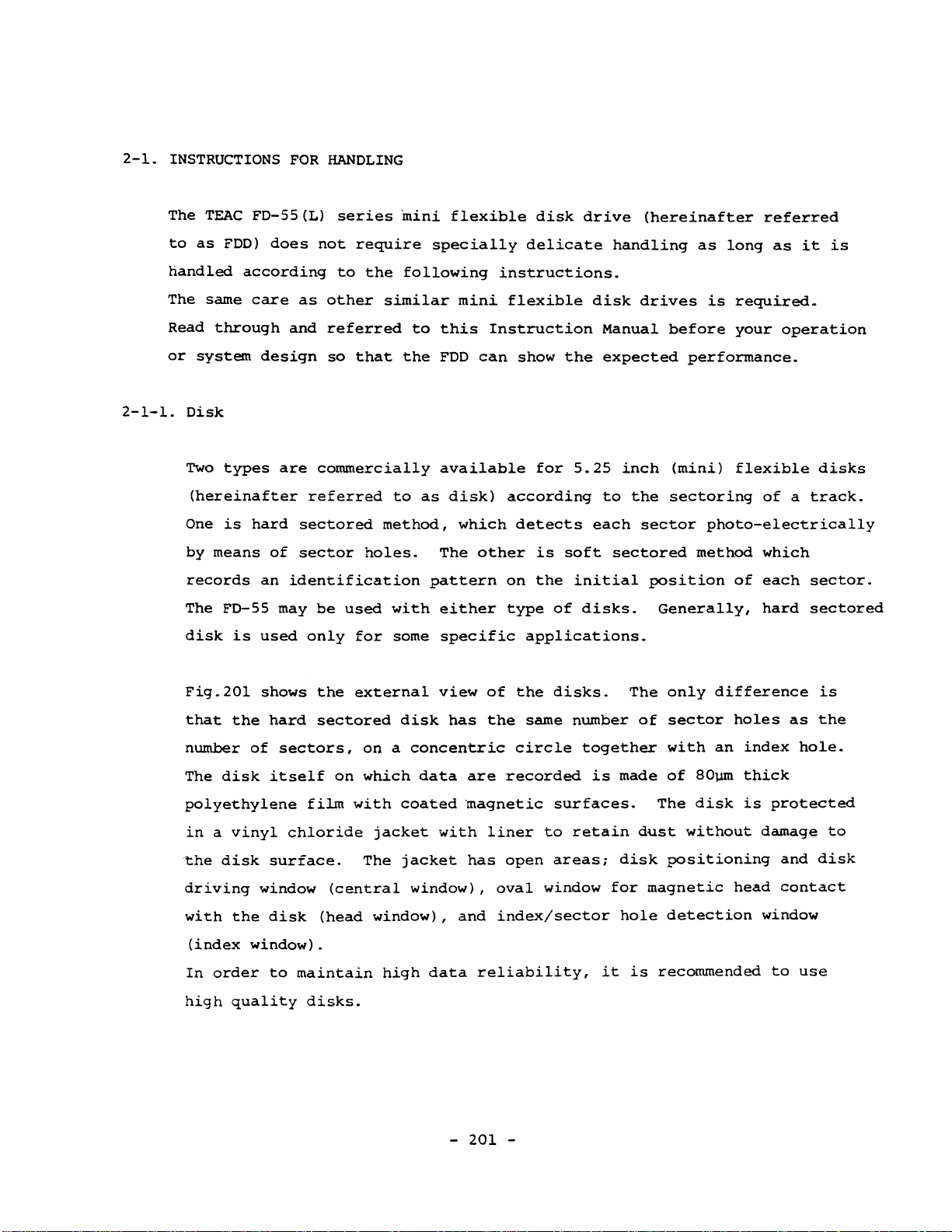
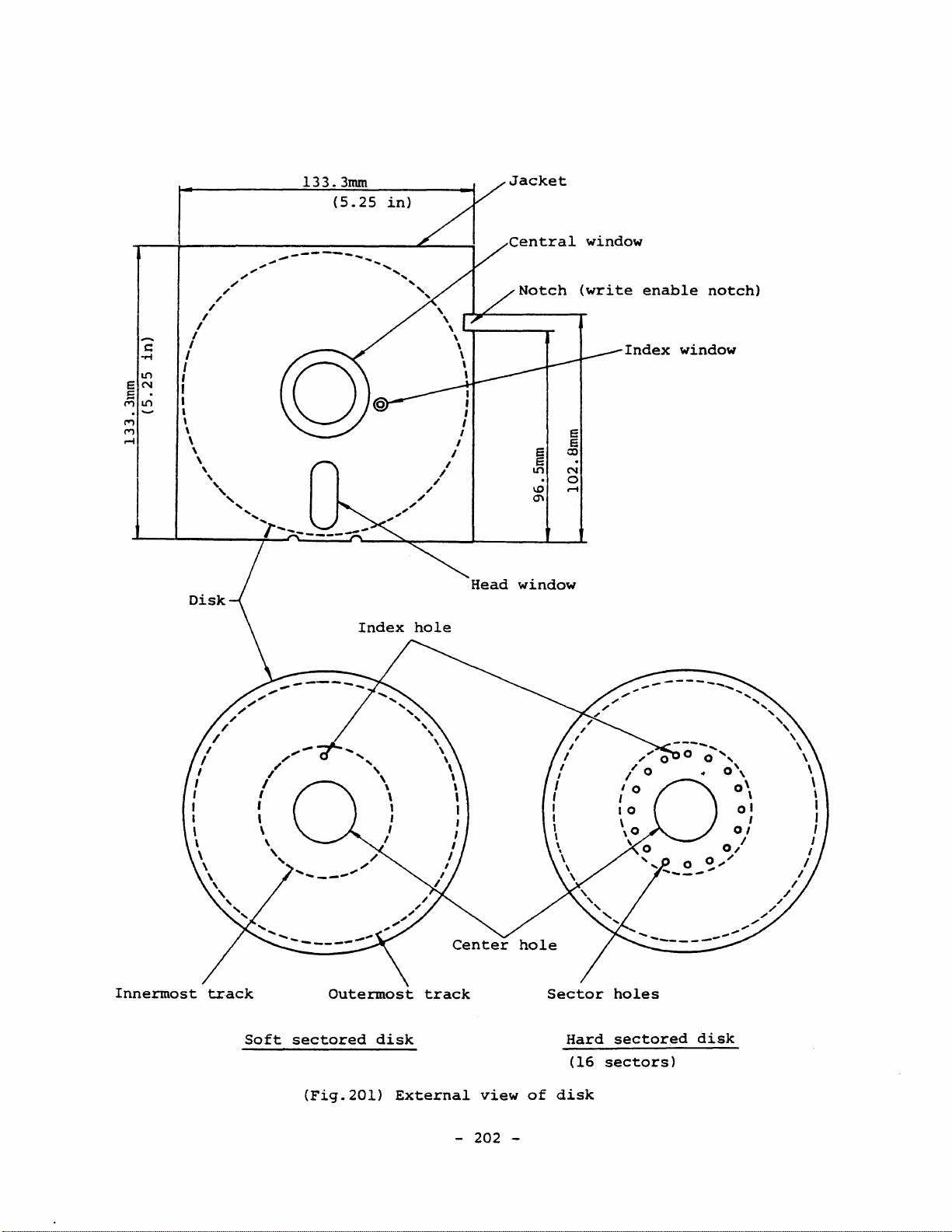
Two
(hereinafter
One
by
means
records
The
disk
Fig.20l
that
according
care
design
types
is
hard
an
FD-55
is
used
shows
the
as
other
and
referred
so
are
commercially
referred
sectored
of
sector
identification
may
be
only
the
hard
sectored
to
that
used
for
external
the
similar
to
method,
holes.
with
some
following
to
this
the
FDD
available
as
disk)
The
pattern
either
specific
view
disk
has
mini
Instruction
can
which
other
of
the
instructions.
flexible
show
for
the
5.25
according
detects
is
soft
on
the
initial
type
of
applications.
the
disks.
same
number
disk
Manual
expected
to
each
sectored
disks.
drives
inch
the
sector
position
The
of
is
before
performance.
(mini)
sectoring
photo-electrically
method
Generally,
only
difference
sector
required.
your
operation
flexible
of a track.
which
of
each
hard
holes
sector.
sectored
as
disks
is
the
number
The
of
disk
polyethylene
in a vinyl
-the
disk
driving
with
the
(index
In
high
window).
order
quality
sectors,
itself
chloride
surface.
window
disk
to
maintain
on
film
(central
(head
disks.
on a concentric
which
with
The
coated
jacket
jacket
data
with
window),
window),
high
data
-
are
magnetic
liner
has
oval
and
index/sector
reliability,
201
circle
recorded
surfaces.
to
open
areaSi
window
-
together
is
retain
for
it
made
The
dust
disk
magnetic
hole
is
recommended
with
of
an
80~
disk
without
positioning
head
detection
index
thick
is
protected
damage
window
to
hole.
and
disk
contact
use
to
133.3mm
(5.25
in)
.-
Central
Notch
I
,
I
I
I
I
I
I
/
/
/
/
"
-,'
'"
Head
window
window
(write
e
e
co
N
o
.....
enable
Index
notch)
window
Innermost
track
I
I
,
,
\
Soft
,,-
/
"
/
Outermost
sectored
(Fig.201)
disk
External
track
Sector
Hard
view
of
disk
-
202
-
(16
holes
sectored
sectors)
disk

There
are
many
types
in
the
commercially
available
soft
sectored
disks
(1)
(2)
which
appropriate
Oata
recording
Single
Da
not
Expected
A
double
All
the
density
Number
Single
1
can
be
are
classified
one
density
density
(FM
use a single
data
reliability
density
models
of
recordings.
of
used
sided
sides
(only
used).
according
for
your
method)
density
disk
can
FD-55A~F
side
0
to
application.
or
Double
disk
will
be
are
can
not
used
be
for
used
used)
the
be
for
following
density
a
double
obtained
a
single
for
both
or
(MFM
double
factors.
method)
density
and
density
single
sided
recording.
error
and
Select
may
occur.
recording.
double
(both
sides
the
0
most
and
Use a double
is
degraded.
A
double
(3)
Track
48tpi
It
density
reliability
Though
cause
used
for a double
sided
density
or
96tpi.
is
recommended
of
such
practical
sided
an
might
an
FOO.
disk
sided
disk
can
to
use a disk
If
be
degraded
application
problem,
for a double
FDO, data
be
used
a
48tpi
disk
rarely.
of
using
it
is
not
-
203
for
of
the
thoughtful
-
sided
reliability
a
single
same
is
used
a
96tpi
FDD.
sided
track
for
disk
to
If
of
density
a
96tpi
for
use
a
the
FDO.
a
in
single
side
as
FOO, the
48tpi
that
sided
1
might
the
FOD
way.
disk
track
data
does
be
not

(4)
Track
Same
35
tracks
numbers
of
commercially
from
track
available
00
to
34.
48tpi
And
single
35
track
sided
disks
FOOs
are
can
used
access
by
only
same
(5)
people
The
operation
40
tracks).
are
not
Almost
40
tracks.
High
density
For
the
use
an
Generally,
Da
not
degraded.
in a few
However,
guaranteed
all
the
disk
high
density
exclusive
disks
use
an
application.
of
the
when a 35
disks
HO
written
HO
disk
FO-55A
the
data
commercially
FDD
(FO-55G)
disko
Da
by
with
FO-55A ~ F.
is
guaranteed
reliability
track
available
which
not
use
an
FD-55A ~ F
disk
is
is
disks
The
for
of
used.
are
put
for
cannot
da
track
five
00
tracks
guaranteed
to
practical
FO-55A ~ F.
be
read
ta
reliability
through
from
for
by
use
an
may
39
<total
35
to
up
to
recently,
FD-55G.
be
39
-
204
-
2-1-2.
Disk
Handling
Disk
precautions.
(1)
Oe
(2)
Oe
the
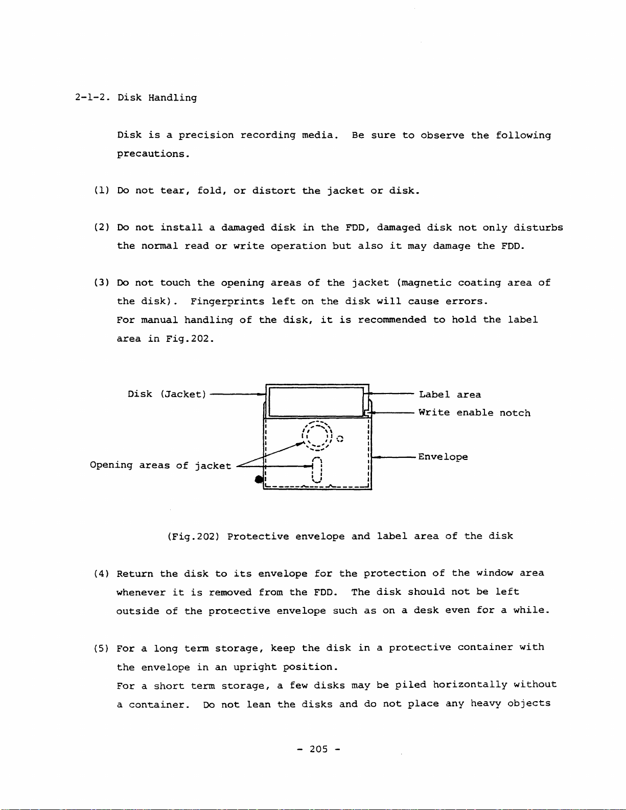
(3)
Oe
the
For
area
Opening
not
not
normal
not
disk).
manual
Disk
areas
is
aprecision
tear,
install
touch
in
Fig.202.
(Jacket)
fold,
a
read
the
Fingerprints
handling
of
jac
or
damaged
or
write
opening
ket
recording
distort
disk
media.
the
in
operation
areas
left
of
the
I
I
I
I
~.,
I
I
~
I I : I
I
L..
__________
•
of
on
disk,
'--::~',
I,
1I
':~,,'
r,
~
jacket
the
but
the
the
it
\\
I I
,"""
I
.J\-
Be
FDD,
also
jacket
disk
is
recommended
I
I
____
I
I
I
I
I
I
I
I
--'
.'"'
sure
or
disk.
damaged
it
(magnetic
will
to
observe
may
cause
Label
Write
Envelope
disk
damage
errors.
to
the
not
coating
hold
area
enable
only
the
the
following
disturbs
FDD.
area
label
notch
of
(4)
Return
whenever
outside
(5)
For a long
the
Far
a
(Fig.202)
the
of
envelope
a
short
container.
it
disk
is
the
term
in
term
Protective
to
its
removed
protective
storage,
an
upright
storage,
Da
not
envelope
from
lean
envelope
the
envelope
keep
position.
a
few
the
-
for
FDD.
the
disks
disks
205
the
such
disk
-
and
label
protection
The
disk
as
on a desk
in a protective
may
be
and
do
not
should
piled
place
area
of
of
even
horizontally
any
the
the
window
not
be
for a while.
container
heavy
disk
area
left
with
without
objects
(6)
such
Keep
as
and
books
use
on
the
the
disk
disk,.
away
which
from
will
dust.
cause
Also
distortion
do
not
install
of
the
a
disk.
dusty
(7)
(S)
(9)
(10)
disk
Generally,
into
cause
Da
Oe
such
surface.
as a feIt
stuck
the
D6
the
Index
data
not
not
as a lead
on
information.
not
eraser
label
the
errors
clip
write
Use a soft
tip
it
the
ruh
out
may
FOO.
the
on
pencil
pen.
is
disk.
the
get
shold
Such
and
jacket.
the
index
desirable
It
information
into
be
dust,
may
shorten
The
label
or a ball
writing
is
recommended
the
applied
clipped
object
not
jacket.
on
if
of
point
to
on
the
carried
the
portion
the
pen
which
write
the
label
to
life
of
jacket
which
will
on a label
to
stick
label
area
the
magnetic
the
disk
will
with
be
with a hard
may
not
damage
which
the
label
an
shown
and
distorted.
damage
is
after
eraser.
in
Fig.202.
head,
the
tipped
the
the
already
Rubbish
may
FDO.
object
disk
disk
writing
such
from
(lI)
(12)
(13)
{14}
Da
not
Keep
motors,
ambient
Da
not
it
damages
Da
not
the
disk
electric
Disks
apply
the
smear
expose
should
more
disks
etc.
stray
the
the
away
apparatus
be
than
away
These
magnetic
disk
magnetic
the
disk
from
heater
such
operated
from
may
with
two
magnetic
degrade
field
coating
to
sunlight,
or
as
within
labels
should
a
solvent
stove.
TV
set.
-
on
the
fields
the
recorded
not
of
the
micro-waves,
Also
the
following
206
-
such
disk.
same
•
such
exceed
as
do
area
.
as
by
data
not
on
50
Oersted.
thinner,
or
put
conditions:
magnets,
the
disk.
freon,
infrared
the
disk
transformers,
The
or
alcohol,
ray.
on
Keep
the
Ambient
temperature:
10°C ~ Sl.soe
(50°F ~ 125°F)
Relative
Wet
The
operating
required
FDD
Generally
limit
good
performance
Also a sudden
within
(15)
Disks
Ambient
humidity:
bulb
above
temperature:
temperature
condition,
against
assembled
upper
of
the
contact
the
should
temperature:
20\ ~ 80\
the
in
a
host
limit
jacket
material
between
characteristics.
change
specified
be
stored
29°C
applies
(84°F),
to
approximately
operating
system
of
the
temperature
because
the
disk
in
environmental
and
range.
within
the
4°C ~ sl.soe
Max.
the
jacket
15°C
limit
into
taking
consideration.
the
the
magnetic
conditions
following
(40°F ~ 125°F)
surface.
of
temperature
the
is
determined
jacket
conditions:
temperature
deformation
head
which
should
In
the
margin
by
adeformation
may
be
avoided
actual
is
rise
disturbs
degrade
in
the
even
Relative
(16)
For
recommended
outer
stray
Disks
Ambient
Relative
Temperature
(17)
Disks
exceeding
Such
humidity:
transportation,
that
surface
magnetic
should
be
temperature:
humidity:
gradient:
which
have
the
disks
should
8% ~ 80%
a
sufficient
of
the
fields
transported
8% ~ 90%
been
operating
be
disks
should
space
final
will
container,
be
negligible.
within
-40°C ~ sl.soe
20oe/hour
stored
or
conditions
subjected
to a conditioning
be
in
the
exists
so
the
following
(-40°F
transported
may
exhibit
protective
between
that
~
125°F)
at
the
risk
of
conditions:
temperature
degradeed
period
container.
recorded
damage
and
perfQrmance.
of
not
disk
due
humidity
less
to
It
is
and
than
-
207
-

(18)
24
When
hours
you
within
install
the
the
operating
disk
to
environment
the
FDO,
be
prior
careful
to
to
use.
handle
it
slowly.
Rough
may
installation
cause
incorrect
will
accelerates
installation.
the
degration
of
the
disk
and
it
-
208
-
2-1-3.
Write
A
write
For
Proteet
enable
reeording
noteh
new
data,
is
loeated
use a disk
on
the
with
right
the
side
noteh
of
in
the
the
disko
eondition
shown
installed
magnetie
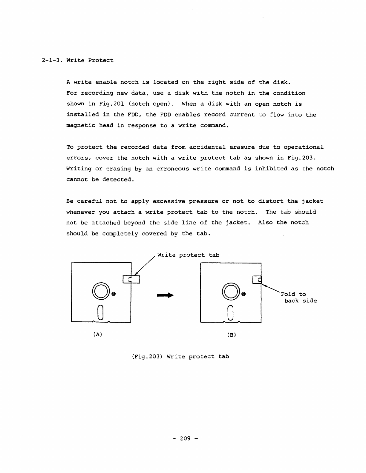
To
proteet
errors,
Writing
eannot
Be
eareful
whenever
not
be
should
in
Fig.201
in
head
eover
or
be
deteeted.
you
attaehed
be
comp1ete1y
the
in
the
reeorded
the
erasing
not
to
attaeh
(noteh
FOO,
response
noteh
by
apply
a
beyond
open).
the
FOO
to a write
data
with a write
an
erroneous
exeessive
write
the
side
eovered
Write
When a
enables
from
proteet
line
by
the
proteet
disk
reeord
eommand.
aeeidenta1
proteet
write
pressure
tab
to
of
the
tabe
tab
with
eurrent
erasure
tab
eommand
or
not
the
jaeket.
an
as
is
to
noteh.
open
inhibited
to
due
shown
distort
The
Also
noteh
f10w
to
is
into
operational
in
Fig.203.
as
the
tab
should
the
noteh
the
the
jaeket
noteh
(A)
(Fig.203)
Write
-
209
protect
-
o·
o
(B)
tab
Q
~FOld
baek
to
side
2-1-4.
(1)
FOO
Handling
The
FOO
Inserting
should
and
be
handled
ejecting
according
procedure
to
the
of a disk
following
should
instructions.
be
performed
according
Insert
(2)
A
sudden
relative
within
at
the
environmental
(3)
Keep
(4)
Remove
time.
(5) Keep
by
transformer,
a
the
new
and
the
the
to
item
disk
correctly
change
humidity
specified
operating
condition.
use
the
disk
FOO
away
2-1-5.
in
environmental
should
range.
condition
FOO
away
from
the
from
stray
magnet,
and
be
from
FOO
CRT
carefully.
conditions
avoided
Sufficient
if
there
dust
when
it
magnetic
display,
as
and
will
etc.
such
far
as
possible
hours
was a
of
sudden
damp.
not
be
or
electromagnetic
as
temperature
even
storage
change
operated
or
if
it
is
required
in
the
for a long
fields
such
is
as
(6)
(7)
(8)
If
such
data
errors
Refer
Da
FDD
For
to
to
,not
except
transportation,
the
apart
item
touch
FDD.
or
the
for
or
equipment
degrades
2-2
for
variable
trained
data
installation
resistors
technicians
refer
to
is
not
reliability.
item
-
2-1-6
210
sufficiently
Refer
of
the
FOD.
or
screw
concerning
not
-
shielded,
to
adjusting
FD-55.
to
apply
it~
2-2-4.
parts
excessive
it
may
in
impact
cause
the
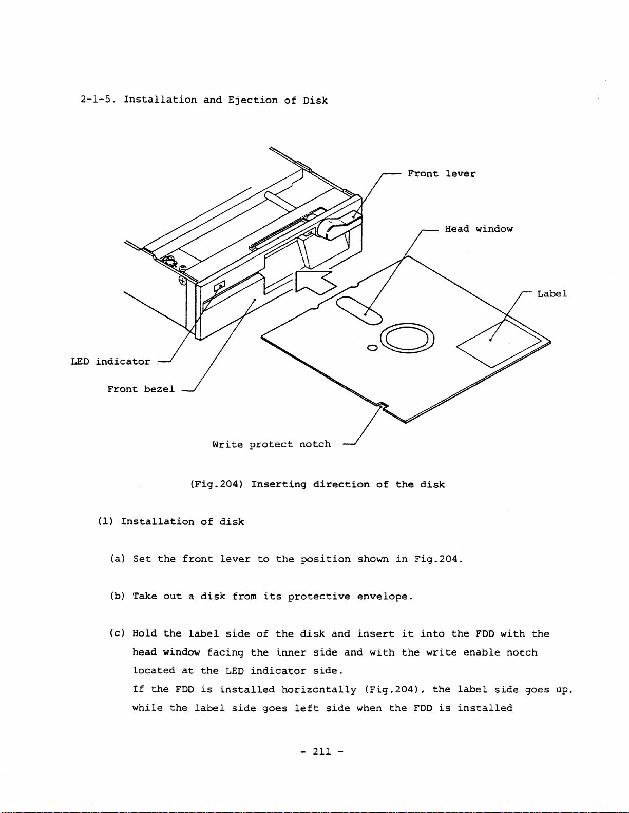
2-1-5.
Installation
and
Ejeetion
of
Disk
LED
indieator
Front
bezel
Write
proteet
noteh
Front
lever
Head
window
(1)
Installation
(a)
(b)
(e)
Set
the
Take
Hold
head
loeated
If
the
while
(Fig.204)
of
front
out a disk
the
label
window
FDD
the
at
faeing
the
is
label
Inserting
disk
lever
from
side
the
LED
indieator
installed
side
to
its
of
goes
the
the
inner
direetion
position
proteetive
disk
side
side.
horizcntally
left
side
-
211
and
and
-
of
shown
envelope.
insert
with
(Fig.204)
when
the
the
in
it
the
disk
Fig.204.
into
write
,
the
FDD
is
the
FDD
enable
label
installed
with
noteh
side
the
goes
up,
(d)
(d
l
vertically
Insert
)
For
the
the
models
with
disk
front
fully
with
lever
and
disk
up.
straightly
eject
option,
into
a
the
light
FDD
with
depressing
enough
force
care.
is
required
before
When
sure
(e)
Take
turning
aution:Never
(2)
Ejection
(a)
Turn
lever.
It
for
the
it
is
to
insert
off
your
90°
elose
fingers.
be
damaged.
of
the
front
is
recommended
the.
bottom.
inserted
in
If
disk
full
it
fully.
fingers
the
~~e
the
lever
to
insertion
to
the
from
clockwise
front
disk
90°
lever
is
in
pineh
of
the
bottom,
the
disk,
a
click
and
direction.
with
clamped
depressing
with
eounterelockwise
the
lever
with
disk
close
bent
from
sound
two
the
can
the
the
eonäition,
direction
fingers
point
be
front
disk
to
not
lcm,approx.
heard.
lever
with
the
open
to
by
your
disk
the
apply
Be
may
(b)
(~)
(e)
excessive
Hold
For
the
Put
from
the
the
the
lever
the
impact.
rear
FDD.
models
is
disk
side
with
open.
back
of
into
the
disk
eject
the
disk
with
option,
protective
-
212
-
your
disk
envelope
fingers
pops
lightly
out
(See
and
from
Fig.202l.
the
draw
FDD
out
when
2-1-6.
(I)
Precautions
The
following
of
the
FOO
In
order
to
for
and
protect
Transportation
precautions
the
system
the
should
in
which
magnetic
be
the
head
referred
FOO
assembly
to
for
is
assembled.
from
transportation
vibration
and
impact
during
FOO.
a
disk,
(a)
The
After
and
(b)
When
projection
sheet
(2) Be
(3)
careful
Since
transportation.
to
package
transportation,
The
protection
is
installed
insertion
closing
fix
the
lever.
ejecting
of
for
another
not
to
the
FOD
is
several
sheet,.
to
of
the
the
front
the
protection
the
sheet
transportation.
expose
small
To
protect
FODs
be
sure
which
all
the
protection
lever,
with
the
FDD
and
light,
the
in
one
to
attach
is
FOOs
sheet
pull
sheet,
your
to
it
FOD
box.
the
made
at
of
the
is
up
the
open
finger.
excessive
might
from
such
protection
thick
shipment
done
like
projection
the
lever
Store
moisture.
fall
or
abuse,
sheet
paper
from
a
disk
of
depressing
the
removed
be
thrown
it
is
to
the
shaped
the
like
factory.
installation.
the
sheet
the
protection
down
recommended
during
(4)
When
should
transportation.
to
absorb
the
be
FOD
enough
impact
is
shipped
strong
Also
so
that
assembled
to
withstand
the
packaging
the
FOD
will
- 213 -
in a system,
vibration
of
the
system
not
suffer
the
and
system
impact
should
from
cabinet
during
be
constructed
excessive
impact.

2-2.
INSTRUCTIONS
FOR
INSTALLATION
2-2-1.
(1)
(2)
Refer
your
system
Precautions
Keep
For
the
excessive
It
is
(natural
heat.
When a
th~
adhered
to
the
following
so
the
FDD
example,
operation
dust.
recommended
air
fan
is
air.
to
If
the
that
for
away
install
ability
cooling
attached
the
FDD.
items
theFDD
Installation
from
dust.
the
of
to
operate
should
in
FDD
is
for
can
FDD
the
the
blown
installing
exhibit
away
FDD.
the
not
system
strongly,
from
Such
FDD
be
obstructed)
and
the
expected
the
floor,
care
in a weIl
cabinet,
a
large
assembling
performance.
without
will
protect
ventilated
to
dissipate
install
quantity
it
of
the
disturbing
the
FDD
situation
the
to
draw
of
dust
FDD
into
from
radiated
out
may
be
(3)
(4)
(5)
(6)
(7)
Da
not
magnetic
up
such
position.
00
not
stove.
Da
not
Da
not
The
screws
surface
place
noise
noises
See
expose
place
place
more
the
the
the
for
FDD
source.
which
item
the
FDD
FDD
installing
than
2-2-4.
FOD
Smm.
near
may
to
in
in
a
strong
The
magnetic
cause
sunlight.
an
environment
a
situation
the
errors.
FDD
magnetic
head
Keep
with
subject
should
Be
the
not
noise
and
careful
FDD
corrosive
to
protrudc
read
strong
source
amplifier
about
away
or a electro-
the
from
heater
air.
vibration.
from
the
will
pick
installing
or
FDD
-
214
-
(8)
Da
not
apply
excessive
force
when
installing
the
FDD
in a system
cabinet.
of
(9)
For
(lO)
For
FDD
The
at
(11)
After
it
Protruding
seek
(12)
Fundamental1y,
indicator
the
magnetic
the
connection
the
setting
PCBA,
setting
shipment.
checking
is
bent
operation,
Frame
refer
and
of
head.
of
to
to
match
Confirm
that
extraordinary,
cable
the
the
may
which
front
the
of
the
item
your
the
be
FOD
FDD
the
straps
2-2-3.
these
head
caught
cause
shou1d
lever
may
be
cables,
(short
system
settings
attach
misalignment
cable
by
be
up
might
the
installed
(magnetic
distorted
refer
bars)
be
before
of
the
FDD
other
which
to
item
and
different
operation.
FDD
to
the
parts
of
the
horizontal1y
head
2-2-2.
the
does
system
or
increases
head
up),
causes
terminator
from
not
protrude
cabinet.
or
seek
with
or
vertica11y
misalignment
on
the
the
setting
nor
load
at
errors.
the
that
head
with
the
left
FDD
should
for a 96tpi
Da
not
orientation
of a disk).
between
head.
As
to
tion
angle
consideration
install
the
the
of
the
against
side
not
FOO
or
These
magnetic
other
right
down
and
the
form a greater
against
the
FDD
the
front
orientation
orientations
side
the
horizontal
is
required.
the
with
head
down
front
horizontal
the
bezel
and
with
angle
magnetic
up
of
the
than
plane
lever
than
in
vertical
the
FDD
disk
explained
the
indicator
than
up.
plane
or
In
30°
head
may
may
above
explained
either
for a 48tpi
with
the
down
orientatiop
disturb
cause
up
in
(such
or
above),
misalignment
forming a greater
orientation,
FOO
and
front
horizontal
the
(top
stable
as
the
separate
bezel
the
15°
up.
loading
contact
of
orienta-
the
- 215 -
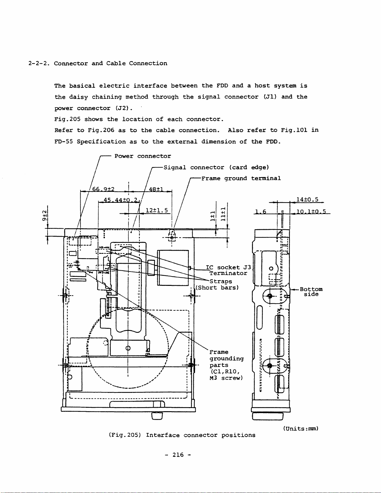
2-2-2.
Connector
The
basical
the
daisy
and
Cable
electric
chaining
Connection
interface
method
through
between
the
the
signal
FDD
and a host
connector
(Jl)
system
and
is
the
N
+1
'"
power
Fig.205
Refer
FD-55
connector
to
Specification
iT/-~~
:t
__
~+
!c:jH"
I
.....
.
....
,....
(J2).
shows
Fig.206
the
45
location
as
Power
q
44+
l
1
r
------·1
__
..:
J
~I::~·
,.
-
=1'
of
each
to
the
cable
as
to
the
external
connector
~r'
12±1.5
;-
~~--.
connector.
connection.
dimension
connector
Frame
~
__
~IC
Terminator
.
Straps
(Short
Also
(card
ground
socket
bars)
refer
of
J3
to
the
FDD.
edge)
terminal
Fig.lOl
.l4±O.5
in
Bottom
side
I
....
Frame
grounding
parts
(Cl,RlO,
M3
screw)
-
--
----
-
--
--
----
--
-----
---
-------
-
-----..}
(Fig.20S)
Interface
-
connector
216
-
(Units
positions
:mm)
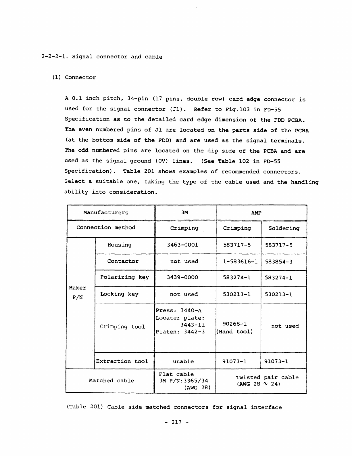
2-2-2-1.
(I)
Signal
Connector
A
0.1
inch
connector
pitch,
and
34-pin
cable
(17
pins,
double
row)
card
edge
connector
is
used
for
the
Specification
The
(at
The
used
even
the
odd
bottom
numbered
as
the
numbered
Specification).
Se1ect
ability
a
suitab1e
into
Manufacturers
Connection
signal
as
connector
to
the
pins
side
of
pins
signal
ground
Table
one,
consideration.
method
Housing
Contactor
detailed
of
the
are
201
taking
(Jl).
Jl
are
FOD)
10cated
(OV)
shows
the
Crimping
3463-0001
not
card
10cated
and
on
lines.
examples
type
3M
used
Refer
are
the
edge
used
(See
of
to
Fig.103
dimension
on
the
as
dip
side
Table
of
recommended
the
cab1e
Crimping
583717-5
1-583616-1
parts
the
of
102
in
of
side
signal
the
in
used
AMP
FO-55
the
FDO
of
the
terminals.
PCBA
and
FD-55
connectors.
and
the
Soldering
583717-5
583854-3
PCBA.
PCBA
are
handling
Maker
P/N
(Table
Po1arizing
Locking
Crimping
Extraction
Matched
201)
Cable
key
cab1e
too1
too1
side
k~y
matched
3439-0000
not
Press:
Locater
P1aten:
F1at
3M
P/N:3365/34
-
used
3440-A
plate:
3443-11
3442-3
unab1e
cab1e
(AWG
connectors
217
-
28)
583274-1
530213-1
90268-1
(Hand
91073-1
for
too1)
Twisted
(AWG
signal
583274-1
530213-1
91073-1
pair
28
'"
interface
not
2 4 )
used
cab1e
(2)
Polarizing
A
the
polarizing
PCBA
card
key
key
slot
edge.
is
The
fitted
between
polarizing
key
pins
No.4
protects
(3)
the
and
No.6
connector
eS)
fram
on
(3)
wrong
No.2
key
As
to
in
far
driver
not
be
turned
data
on a track
Locking
When
pin
For
the
i5
you
two
numbers
used
fixing
Fig.103
connection
the
position
the
cable
as
the
open
of
the
damaged
on.
However,
key
use
two
positions
33
for
the
the
(FD-SS
(connection
of
side
connector.
collector
host
even
system
if
the
if a disk
will
be
locking
for
locking
and
34)
cannot
READY
locking
signal.
keys,
Specification)
of
No.33).
type
side
connector
erased.
keys
~2
pin
(FDD
is
(AMP
key
be
holes
are
No.l
It
is
driver
controller
is
installed
P/N
insertion
used
for
above
used.
to
the
position
recommended
is
used
for
side),
inserted
530213-1)
signal
in
(pin
the
wrongly
this
with
numbers
and
pins
of
No.34
to
use a polarizing
the
interface
the
circuit
and
power
condition,
AMP
P/N
land
OV
lines.
No.2
and
and
will
is
recorded
583717-5,
2,
and
Pin
No.34
No.34
in
(4)
Cable
The maximum
of
For
an
of
a
multiple
reflection
of
Therefore,
length
transferred
the
simple
interface
the
cable,
the
cable
cable
length
waveform
model
receiver
considerably
connection
of
the
output
is
greater
the
maximum
is
which
which
easily
is
has
caused
an
interface
influenced
having a terminator
10ng
cable
of
FDDs
siqnals
since
cable
such
fram
one
length
as
end
allowed
- 218 -
by
can
daisy
the
of
the
by
disorder
mismatching
driver
resistor
be
used..
chaining
FDD
connected
cable
is
shorter
or
of
the
at a cable
at
the
another
Contrarily,
in
Fig.206,
on
the
is
open
condition.
than
distortion
impedance.
end
and
end
for
the
halfway
the
above
explained
simple
model.
In
the
case
of
LI < L2,
shown
in
Fig.206,
the
allowable
Enough
For
at
and
receivers
the
Therefore,
for
Though
of
chain
(Refer
Terminator
Terminator
care
the
system
host
host
and
determine
total
the
system
the
side
connection
to
cable
is
FDD
of
both
cable
it
length
receiver,
item
resistor
resistor
length
required
design,
sides
the
length,
is
construction.
2-2-3-1).
carefully
maximum
sides
recommended
is
different
is
as
3300
lKn
is
remarkably
for
such a case.
observe
cable
to
receive
the
better
the
maximum
follows:
the
input/output
assuming
length
the
for
to
select
depending
cable
3m,Max.
1.5m,Max.
shortened.
the
which
signals
the
system
the
appropriate
on
types
length
signal
cable
enables
connections
correctly.
performance.
of
in a typical
waveforms
the
interface
length
cable
The
and
daisy
both
possible,
shorter
of
cable
types
oe
+12V,+5V L2
control
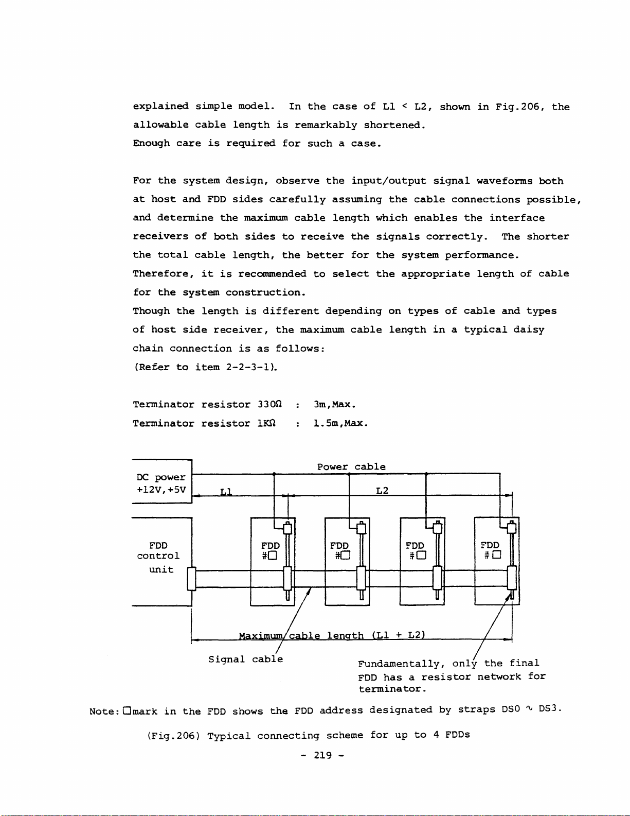
Note:Omark
power
FDD
unit
in
the
(Fig.206)
Power
~--~~------~~---------+----~~----~----------~~
Signal
FDD
Typical
cable
shows
connecting
the
FDD
address
- 219 -
cable
scheme
Fundamentally,
FDD
has a resistor
terminator.
designated
for
up
to 4 FDDs
by
only
straps
the
final
network
DSO ~ OS3.
for

(5)
Connecting
Be
sure
to
and
disconnecting
turn
the
power
off
the
first.
connector
When
you
plug-in
the
connector,
check
the
excessive
by
pulling
1
and
34)
orientation
force.
the
cable,
of
the
cable
If
of
you
since
are
the
connector
use a flat
the
outermost
easily
cable,
broken
and
by
plug-in
never
lines
excessive
straightly
disconnect
(corresponds
force).
without
the
to
connector
pin
Nos.
-
220
-

2-2-2-2.
(1)
Power
Connector
A
nylon
connector
housing,
and
'4-pin
cable
connector
is
used
as
the
power
connector
(J2).
Table
This
202
connector
construction.
Be
sure
to
connector.
Connection
Maker
P/N
shows
an
prevents
turn
the
Manufacturer
Housing
Contactor
Crimping
Extraction
examp1e
power
method
wrong
tool
tool
of
recommended
connection
off
before
or
connecting
1-480424-0
170148-1
60617-1
90123-2
1-305183-2
connector
because
AMP
Crimping
for
of
the
or
disconnecting
60619-1
90124-2
1-305183-2
the
cable
housing
side.
the
(2)
(Table
Cable
Determine
at
J2
connector
and
(2)
cab1e
and
Matched
202)
the
in
FD-55
the
cable
Cable
thickness
will
Specification,
maximum
side
be
matched
and
in
power
AWG
connector
the
1ength
the
specified
taking
consumption
-
221
24
-
""
18
of
tolerance
the
of
for
the
volcage
the
AWG
power
cable
FDD
20
""
interface
so
range
drop
into
14
that
the
in
item
through
consideration.
voltage
1-4
the
(1)

Use
(see
the
Table
correct
202).
contactor
and
crimping
tool
to
suit
the
cable
thickness
- 222 -

2-2-2-3.
Frame
As
described
to
the
grounding
in
frame
of
item
the
1-10
FOO
of
FO-55
through
Specification,
Cl
(O.OlpF,
500V)
oe
and
OV
RIO
is
connected
(lOOKO)
in
parallel
at
Fig.205.
connectors
the
M3
screw
oe OV-Frame
acceptance
system).
applications
methods
Another
(1)
When
(2) When
(For
However,
in
frame
the
the
example,
shipping.
Cl
and
are
located,
for
connection
inspection
from
item
(A)
grounding
FOO
FOD
RIO
are
frame
purpos~
this
items
~
is
assembled
is
installed
installed
Refer
mounted
and
they
grounding
by
O.Ol~F//
connection
(1)
to
(C)
is
is
required:
on
to
Fig.109
on
the
are
connected
(see
100Kn
for
FOO
is
(3).
Secure
required.
in a system
or
placed
the
vibration
in
FO-55
PCBA
on
Fig.205).
is
sufficient
unit
only
insufficient
connection
cabinet.
on a metallic
tester,
Specification
which
to
the
interface
frame
for
(not
assembled
for
plate
placed
the
by
and
through
shipping
in
the
following
one
of
the
during
on a metallic
or
tests.
plane
(3)
Ouring
Another
(A)
Connect
cabinet
Specification).
to
(B)
Utilizing
side
in
electro-static
frame
the
with
oe
OV
of
the
thermostatic
grounding
FOO
frame
the
installation
It
of
the
power
the
frame
FOO,
connect
oven)
noise
method:
securely
is
required
supply
ground
the
- 223 -
test.
to
taps
for
unit
terminal
frame
the
(refer
the
by
an
(faston
ground
metallic
to
system
appropriate
securely
cabinet
Fig.10l
cabinet
terminal)
(system
in
tQ
methode
at
to
OC
FO-55
be
the
OV
of
connected
rear
the

(C)
power
AWG
14).
Connect
to
oe
supply
the
OV
through
unit
test
through
plane
a
low
a
low
or
test
impedance
impedance
equipment
cable.
cable
used
Otherwise,
for
(thicker
testing
insert
than
the
a
FDD
thick
If
any
(Cl,
If
it
off
one
If
oe
from
the
result,
insulation
vibration
of
RIO,
is
unavoidable
Cl
and
and
execute
OV
electro-magnetic
static
expected
the
M3
screw)
RIO
and
the
electricity
tester).
above
plate
with
one
frame
reliability
between
methods
in
the
to
remove
a
cutting
of
either
are
inductive
generated
the
FDD
is
executed,
FDD
may
these
plier
(A)
completely
noises
by
will
still
or
not
and
parts
or
(B)
the
the
the
be
replace
method.
open,
and
moving
be
obtained.
test
frame
mounted.
for
system
.
the
the
there
parts
plane
grounäing
M3
FDD
is
(unsuitable
construction,
screw
is
easily
no
way
in
the
parts
with
suffered
to
discharge
FDD.
a
plastic
And
for
cut
in
-
2~4
-

2-2-3.
Setting
The
FDD
of
Straps
is
equipped
and
with
Terminator
16
straps
and a terminator
resistor
network.
Users
Be
set
1-11
The
double
Refer
(4 FDDs,Max.)
sure
for
and
short
can
to
your
row
to
select
check
1-12
bars
pins
Fig.206
an
that
system
in
FD-55
and
and
as
appropriate
the
be
fore
Specification.
the
terminator
IC
socket
to
the
setting
short
bars
operation
J3
connection
resistor
on
the
for
and
the
according
network
bot
tom
of
several
their
terminator
to
side
FDDs
systems.
this
are
PCBA.
are
item
mounted
by
daisy
correctly
or
items
on
the
chaining
- 225 -

2-2-3-1.
(I)
Terminators
FDD
side
and
terminator
interface
drivers
Terminators
at
shipment
Terminator
separated
to
the
ion).
a
14-pin
Input
signals
Other
bottom
All
resistor
DRIVE
DRIVE
DRIVE
DRIVE
input
fo~
(refer
resistor
from
terminators
side
the
terminators
SELECT
SELECT
SELECT 2
SELECT 3
signals
the
network
0
1
input
to
for
PCBA
1-
1
item
the
of
interface
1-8-1
DRIVE SELECT 0 ~ 3
for
the
the
FOD
except
and
mounted
Strap~
DSO
OSI
OS2
OS3
Terminator
h3 L
\!.4
~~
signals
(3)
in
other
(refer
for
the
on
FDO
RAI
.--:::
__
j;
________
FD-SS
input
the
--,
__
-J
are
equipped
Specification}.
input
signals
to
Fig.102
DRIVE SELECT
IC
socket
-
PCBA
Rl3
Fixed
terminator
+SV
GI
~2
L-~--~-to
resistor
.....
+
~~to
network
SV
internai
to
signals
and
in
FO-SS
are
J3.
internal
circuit
all
the
is
is
soldered
Specificat-
packaged
(soldered)
circuit
(7-circuits)
FDDs
as
FO-55{L)
Table
each
The
1Kn
generation.
203
type
feature
type
series
shows
of
of
is
the
(Fig.207)
has
two
the
details
termination.
3300
type
relatively
Terminator
types
of
is a relatively
low
-
connection
of
termination
resistor
current
226
-
in
FOD
(3300
values
longer
consumption
and
cable
type
LQW
and
and
level
length
low
lKO
current
and
noise
type).
that
for
of

Items
3300
termination
type
FD-55(L)
lKSl
type
termination
Resistor
value
DRIVE
line
(LOW
Other
signal
(LOW
Interface
SELECT
current
level)
input
level)
driver
Notes:
current
1.
Resistor
2.
TTL
DRIVE
Other
Terminator
Internal
Total
Terminator
Internal
Type
Sink
74LS38
the
interface
SELECT
input
current(il+i2)
current
values
or
(Table
(Rl3)
signal(RAl)
current(il)
circuit
current(i3)
circuit
capability
and
7438
driver.
203)
Details
current(i2)1
current(i4>
input
are
used
signal
in
of
FDD
I
,
I
'!'TL
48mA(0.4V}
line
an
FDD
termination
3300
3300
l4.8mA
1.6mA 1.6mA
l6.4mA
l4.8mA
0.4mA
7438
current
of
lKn
I
are
type
types
TTL
l2mA(0.4V}
24mA(0.5V}
typical
termination
4700
11m
10.4mA
l2mA
4.9mA
0.4mA
74LS38
7438
values.
or
as
(2)
Installation
For a multiple
network
resistor
However,
in
sink
FDDs.
network
multiple
Also
halfway
It
is
host
and
only
on
networks
if
the
current
For
such a case
and
additional
resistor
when
and
the
distances
may
have
recommended
FDD
sides
removal
connection
the
final
on
the
interface
capability,
networks
resistor
to
observe
actually
of
of
FDD
other
driver
that
FDDs
are
between
network
terminators
FDDs
resistor
an
are
the
for
- 227 -
in
as
shown
FDDs
FDD
rather
using a pair
of
the
already
externally
each
instead
inp~t/output
the
design
daisy
networks
FDD
chaining,
in
Fig.206,
host
connected
favorable.
are
cf
of
of
side
may
systemed
rather
the
final
signal
the
leave
and
tweezers.
has
sufficient
be
left
has
in
short,
waveforms
system.
the
remove
on
resistor
daisy
an
FDD.
terminator
the
margin
multiple
chaining,
FDD
in
of
the
the
(3)
Host
Use
side
the
terminator
same
resistor
value
as
the
host
side
terminator.
Or
use a smaller
(4)
(5)
resistor
side
driver.
If
the
FOO
the
minimum
FOO
side
Refer
Host
to
side
Required
satisry
For
DRIVER SELECT
Driver
capability
value
side
driver
table
driver
current
the
within
driver
for
TTL
203
sink
following
signaliine:
>
the
is
74LS38.
and
item
capability
expression
Terminator
allowable
TTL
7438,
(2).
current(il)
sink
l20n
(IoL)
~efer
current
is
for
to
the
minimum,
the
host
Fig.2071.
+
internal
capability
side
circuit
of
while
driver
the
FOO
430n
is
should
current{i2)
For
other
Driver
LOW
level
than
as
even
O.4V.
TTL
though
WRITE
received
input
capability
output
74LS38
DATA
and
with
For
cannot
it
a
signal
>
voltage
example,
has
24mA
IN
USE/HEAD
Shumitt
lines:
[Terminator
mountedJ
FOD
connected]
(VoL)
for
be
used
capability.
LOAD
TTL
which
current(i3}
+
[Internal
of
the
FOD
since
signals,
-
228
the
host
with
only
Especially,
LOW
level
-
circuit
side
330n
l2mA
since
x
No.
driver
terminator,
is
guaranteed
care
these
threshold
of
resistor
current(i4)
shall
is
required
signals
is
networks
x
No.of
be
less
such a driver
for
VoL ~ O.4V
are
O.5V(Min.)
for
the

2-2-3-2.
On
Straps
the
bottom
side
PCBA
of
the
FOO,
16
straps
are
mounted.
They
are
divided
PM
block.
into
three
HS
OSO
DSI
HM
DS2
DS3
MX
pin
Cl
(]
0
(]
(]
0
Cl
blocks
Cl
(]
(]
(]
(]
0
(]
that
are
HS ~ MX
~
PM
Cl
Cl
UR
Cl
(]
(]
Cl
(]
[]
0
MI,
IU
HL
SM
UO
Ul
RE
Cl
(]
(]
Cl
Cl
(]
(]
block,
UR ~ RE
block,
and
of
Specification
the
SpecificatiQn.
short
at
(1)
Installation
Installation
the
Insertion
the
to
the
short
shipping
power.
strap.
most
bars,
(Fig.208)
of a short
Straps
at
shipping.
appropriate
bars
referring
Since
it
is
stage.
and
removal
and
removal
bar
are
many
desired
Straps
onto
set
condition
to
combinations
to
of
short
of
short
The
this
reset
-
and
the
to
229
their
post
the
setting
for
item
it
bars
bars
-
locations
pin
condition
can
the
system
or
to
are
by
users
must
is
defined
in
be
easily
items
possib1e
to
be
done
as
the
item·1-11-4
changed
construction.
1-11,
avoid
after
for
1-12
setting
the
turning
on-state
of
FD-55
by
user
Reset
in
the
confusion
off

(a)
Installation
Install
in
the
on-state,
of
(b) Removal
To
short
nipped
Be
(2)
Ordering
If
more
or
if
parallel)
short
the
post
protect
bars
up
careful
of
short
short
a
short
bar
it
from
are
with
not
short
bars
bar
in
Fig.208.
insertion.
is
recommended
pins.
unwanted
very
fingers,
to
damage
bars
bars
than
as
securely
securely
spare
pull
the
parts
to
There
However,
to
removal
inserted.
up
the
parts
standard
are
short
is
no
for
insert
due
slowly
around
installation
required,
the
two
restriction
the
easy
the
metal
to
vibration
If
it
with a small
it.
order
pins
visual
bar
is
at
lleft
for
at
and
not
round
shipping
with
and
the
approach
checking
the
upper
impact,
removed
nose
the
following
right
the
when
are
of
of
the
side
pliers.
required,
(3)
parts
Short
HS
(a)
number.
bar
~
MX
strap
MX
strap
The
on-state
to
the
condition
The
off-state
are
daisy
DRIVE
to
SELECT
set
TEAC
Maker
block
system.
independent
chained
the
MX
P/N
P/N
of
this
All
of
input
strap
:
13121149
: Honda
strap
the
this
or
when
signal
off
Tsushin
is
input/output
of
the
strap
is
input/output
for
of
any
used
DRIVE
used
only
daisy
Kogyo
when
only
signals
SELECT
when
signals
one
FOD
chained
Co.,
Ltd.
one
are
signal.
multiple
connected.
FDD
DIC-S252
FDO
is
valid
FODs
are
in
(4 FODs, Max.)
enabled
It
in a multiple
connected
this
by
the
is
necessary
-
230
-

connection.
(b)
This
strap
indicator
DSO
'V
These
multiple
When
as
Any
The
FDDs
for
the
an
of
OS
are
each
Refer
straps
the
front
and
DS3
straps
straps
control
MX
on-state
the
strap
set
input
to
items
(or
the
bezel
has
no
the
rotating
designate
by
strap
four
must
is
OS
strap
addresses
be
to a single
signal
2-2-3-3
DRIVE SELECT
indicator,
relation
daisy
off,
set
and
to
condition
the
drive
cahin
the
enables
0
to
address,
cause
through
spindle
the
number
connection.
same
all
through
different
function
2-2-3-5
signals)
turn~on
of
condition
the
(addressl
number
the
3
of
input/output
can
be
number
they
start
errors
for
and
the
motor,
or
spindle
the
designated.
for
operation
and
the
relation
operating
head
of
the
front
motor.
of
the
FDD
DRIVE SELECT
signals.
each
FDD.
simultaneously
data
errors.
between
conditions
load
solenoid.
in
signal
If
bezel
the
multiple
these
of
(c)
HS
and
These
i)
For
Only
HS
When
executed
while
the
Never
ON
inherent
RH
straps
straps
the
when
and
the
determine
model
the
HM
SM
by
the
head
SM
and
set
both
and
DRIVE SELECT
functions
straps
and
the
the
the
with
SM
head
strap
become
the
HS
DRIVE SELECT
loading
HM
straps
the
HS
and
signals
of.
these
head
load
in
the
effective.
straps
will
are
RH
load
solenoid:
UR
are
signal
be
executed
on.
straps
will
two
signals.
condition.
'V
RE
on,
the
selected
on
be
wired
strap
by
at
block
head
by
the
the
ORed
loading
DSO
MOTOR
same
which
is
'V
time.
on-state,
will
DS3
straps,
ON
signal
The
disturbs
be
when
MOTOR
the
-
231
-

ii)
For
HS
the
and
model
HM
straps
without
have
head
no
load
meaning
solenoid
for
CSS
(CSS
model):
(Contact
Start/Stop)
models.
(4)
{al
Even
influence
these
UR ~ RE
IU
and
Straps
(signal
i)
For
When
as
DRIVE SELECT
indicator
though
straps
strap
HL
straps
to
select
connector
the
the
the
IN
to
block
model
IU
USE
and
one
the
should
the
with
strap
signal.
signal,
to
of
other
pin
control
these
functions.
be
set
function
number
head
is
on-state,
The
is
straps
to
of
is
4)
load
solenoid:
IN
provided
the
rotation
is
set
However,
off-state.
the
IN
the
signal
USE
function,
to
to
on-state,
USE/HEAD
of
turn.
on
of
the
it
as a general
LOAD
pin
independent
the
spindle
input
number 4 functions
front
bezel
motor
will
of
have
rule,
signal
the
by
no
setting
the
ML
strap
the
operating
motor.
If
HL
strap
the
HEAD
loading
is
off,
of
the
HEAO
DSO ~ DS3
It
is
possible
same
time.
functions
Also
both
both
functions
LOAD
will
the
straps.
of
straps
in
item
conditions
is
on-state,
signal.
be
executed
head
LOAD
In
loading
signal
to
set
such a case,
the
IN
may
of
the
(d).
USE
be
of
the
If
by
will.
and
both
and
set
signal
-
Refer
the
the
the
the
of
the
the
to
232
to
items
front
signal
MX
be
the
off
will
-
of
strap
HEAD
DRIVE SELECT
signal
HEAD
LOAD
executed
IU
and
LOAD.
at
be
invalid.
bezel
pin
is
of
the
2-2-3-3
indicator
number 4 functions
on
signal,
by
the
pin
same
and
2-2-3-4
and
at
this
time,
while
the
ANDed
signal
HL
number 4 has
straps
time.
selected
In
spindle
as
the
the
MX
condition
by
on
at
the
two
such a case
for
head
strap

ii)
CSS
For
no
model:
the
means.
CSS
model
Even
without
though
the
head
on-state
load
solenoid,
of
the
HL
the
strap
HL
strap
has
has
no
(b)
previous
SM
strap
Strap
i)
For
When
determined.
For
SM
not
strap
influence
rule.
Only
to
the
used
the
must
be
the
enable
executed.
becomes
IU
item
model
with
model
be
on-state.
to
the
strap
i)
the
HS
with
the
(Refer
with
ineffective
other
as
head
HS
head
If
is
and
or
to
If
both
functions,
effective
to
its
HM
load
the
item
load
both
of
and
function.
strap
solenoid:
HM
(3)-(c)-i».
solenoid,
of
them
this
set
it
for
the
CSS
function
strap,
them
are
head
one
are
on,
combin~tion
to
in
of
off,
the
off-state
models.
the
load
the
head
function
will
Refer
HS ~ MX
condition
straps
loading
of
not
as a general
to
strap
HL
the
be
block.
is
and
will
HS
used.
(c)
ii)
UO,
Straps
By
Refer
load
CSS
For
means.
to
the
Ul,
the
to
item
solenoid.
model:
the
CSS
model
Even
other
UR
straps
to
determine
combination
2-2-3-5
without
though
functions,
the
of
four
as
the
turn-on
to
the
head
on-state
set
it
straps
-
233
operating
load
of
to
off-state
condition
including
-
solenoid,
the
SM
of
the
condition
the
strap
as a general
the
front
IU
has
strap,
SM
of
strap
no
bezel
the
head
has
influence
rule.
indicator.
six
turn-on
no

conditions
in
item
2-2-3-3
can
be
selected.
Any
other
combinations
Never
circuit
(d)
ML
Strap
external
When
controlled,
MOTOR
When
MOTOR
For
motor
than
front
item
these
set
of
strap
to
select
command.
this
ON
input
this
bezel
ON
signal.
example,
2-2-3-3
of a desired
six
are
not
both
strap
the
the
FOO
the
is
UO
and
might
rotating
off-state,
as a commercially
signal.
strap
is
indicator
if
"Selection
and
the
on-state,
turns
on-state
one
used
be
or
practically.
UR
straps
damaged
condition
start/stop
available
the
on
in
6"
of
of
desired
on
partially
spindle
addition
the
Jndicator
the
ML
multiple
at
the
same
(READY
of
the
spindle
of
the
conventional
motor
to
the
strap
are
FOOs
time.
spindle
will
TRUE
turn-on
combined,
among
signal
motor
FDO,
rotate
state
conditions
the
The
motor
by
while
daisy
internal
circuit).
by
an
can
the
of
the
spindle
be
the
in
chained
IN
necessary
current
spindle
overlapping
(current
Select
your
(e)
RE
This
When
track
And
USE
system
strap
strap
this
in
(4
FOOs,Max.)
and
the
FODs
consumption.
motors
of a start
limit
the
most
referring
is
strap
00
after
the
following
can
DRIVE SELECT
improves
Also
respectively
(rush)
value)
can
appropriate
to
effectively
is
on-state,
power
on
and
operation,
be
the
be
item
used
rotated
signals.
life
shifting
(start
current,
decreased.
spindle
2-2-3-4.
in
the
the
of
a
head
track
the
with
disks
the
time:
motor
high
FOD
a
desired
Rotating
and
start
40Omsec,Max.j
peak
current
rotatin~
density
is
automatically
counter
memorizes
the
heads
timing
FDD
in
the
timing
spindle
and
of
to
capability
condition
(FD-55G(L».
recalibrated
FDD
the
track
by
motor
decreases
multiple
avoid
for
is
cleared.
position
the
of
the
the
required
only
to
-
234
-

and
switehes
the
low
pass
filter
Cswiteh
filter)
of
the
read
amplifier
(5)
PM
Strap
of a disk.
between
The
(refer
traek
automatie
to
eompletes
traek).
reealibration.
The
RE
strap
Sinee
this
the
strap
automatie
other
is
not
funetions,
exeeuted)
strap
to
make
43
reealibration
item
1-8-1
within
The
READY
should
switeh
is
effeetive
reealibration.
the
spindle
and
traek
(13)
in
255msee
output
be
filter
(if
signal
set
is
only
Though
set
the
strap
as a general
motor
44.
starts
to
not
FD-55
the
on-state
used
for
to
rule.
rotate
at
the
Speeifieationl
head
was
maintains
for
in
FD-55A ~ F,
the
exeeution
there
will
off-state
automatieally
initial
loeated
FALSE
FD-55G(L}.
of
be
no
(automatie
pre-ready
after
on
the
during
the
previously
influenee
at
the
eondition
power
on
innermost
automatie
on-state
mentioned
to
the
reealibration
insertion
of
When
by
the
When
the
FDD
eonditions.
(a)
When a disk
eb)
wnen
when a write
Automatie
(A) When
beeomes
spindIe
(B)
lOsee,
this
this
strap
FDD
strap
internal
the
rotation
the
the
motor
approx.
internal
is
disk
proteeted
front
ready
is
off-state,
is
on-state,
eireuit
inserted
is
removed.
will
lever
is
not
after
eireuit
is
state
input,
the
will
into
disk
stop
elosed,
automatie
will
automatie
be
(Note
is
in
(as
far
the
removal
not
be
exeeuted
the
front
that
removed~
either
disk
as
an
READY
of a disk
rotation
exeeuted.
rotation
in
bezel.
automatie
of
the
starts
external
signal
of
of
either
following
rotation,
eommand
maintains
from
the
the
of
rotation
the
FDD.
spindie
spindle
the
following
will
two
and
to
FALSEl
motor
motor
not
eonditions.
the
FDD
rotate
by
two
start
the
235
-
-

(6)
Or
in
and
the
Summary
a
of
rare
front
strap
ease,
lever
seleetion
when a disk
is
not
elosed
is
inserted
for
losee,
at
approx.
the
index
hole
position
Table
204
Front
turn-on
Spindle
rotation
Head
operating
FDD
address
designation
Automatie
reealibration
shows
Items
bezel
eondition
motor
load
the
indicatorl
eondition
solenoid
eondition
(Table
proeedure
I
I
204)
Table
of
the
Related
With
load
head
solenoid
IU,UO,Ul,UR
ML,PM
HL,SM,HS,HM
OSO
tU OS3,
RE
(G
model)
of
strap
strap
MX
seleetion
seleetion.
straps
CSS
model
IU,UO,Ul,UR
ML,PM
OSO
tU OS3,
RE
(G
model)
Items
to
be
referred
2-2-3-3
2-2-3-3
2-2-3-4
-
MX
2-2-3-5
2-2-3-2
(31-
Ca)
,
(b)
2-2-3-2
(4)-(e)
-
236
-

2-2-3-3.
Turn-on
conditions
of
front
bezel
indicator
Table
Six
combinations
Selection
No.
1
2
3
4
5
6
Notes:
205
1.
2.
3.
shows
Strap
IU
-
-
ON
ON
ON
ON
li_ti
Any
be
Never
the
turn-on
can
be
combinatio~
UO
Ul
-
-
ON
ON ON
-
-
-
- - -
ON
-
mark
other
used
indicates
combinations
practically.
set
UO
selected
'UR
-
ON
-
-
-
and
condition
by
Indicator
DRIVE
DRIVE
IN
IN
DRIVE
DRIVE
the
UR
straps
of
four
SELEC'r
SELECT
USE
USE
SELECT
SELECT
off-state
of
straps
on
the
straps
latch
at
front
turn-on
x
+
+
of
than
the
of
conditions
Ready
IN
USE
USE"'
IN
the
the
same
bezel
IU,
latch
strap.
above
time.
indicator.
UO,
will
Ul
and
UR.
not
(1)
(2)
(3)
(Table
Selection
is
the
indicator
the
inserted,
When
the
Selection
When
ready
Refer
Selection
205)
1
DRIVE SELECT
turns
2
condition
state,
to
item
3
the
front
1-8-3
Front
input
on.
of
selection
indicator
lever
(13)
be~el
signal
turns
closed,
in
FD-55
indicator
1
is
on.
and
Specification
turn-on
selected
satisfied
Ready
the
disk
conditions
by
DSO ~ 3
and
state
rotates
means
for
also
normally.
details.
~traps
the
that
is
FDD
a
TRUE,
is
disk
in
-
237
-

When
the
IN
USE
signal
(signal
connector
pin
No.4)
is
TRUE,
the
indicator
(4)
(a)
(b)
turns
Selection
When
the
The
DSO ~ 3
(signal
The
by
DSO ~ 3
IN
USE
on.
IN
IN
4
IN
USE
USE
flip-flop
straps
connector
USE
flip-flop
straps
flip-flop
becomes
pin
becomes
~
t-...J
in
the
FDD
is
set,
is
set
when
TRUE
No.4)
is
during
reset
TRUE
;----------------.
__________________
when
during
the
DRIVE SELECT
TRUE-state
the
FALSE-state
the
indicator
signal
of
the
DRIVE SELECT
of
J
IN
signal
the
turns
selected
aSE
selected
IN
USE
on.
by
signal
signal.
(5)
(6)
DRIVE SELECT
IN
USE
flip-fl
Selection
The
indicator
Selection
5
6
op
(Fig.209)
turns
C
Set
on
IN
in
Indicator
Indicator
500ns,Min.
USE
signal
either
turns
turns
of
1
on(Selection
on
latch
the
conditions
{Selection
500ns,Min.
(Selections
4)
6)
of
Selections
4
Reset
and
1
I
i
I
6>-
I
j
I
I
.
land
3.
-
238
-

The
indicator
turns
on
in
either
of
the
conditions
of
Selections
1
and
4.
Note:
The
FDDs
factory.
are
set
to
the
condition
of
Selection
5
at
shipping
from
the
-
239
-

2-2-3-4.
Rotating
eonditions
of
spindie
motor
(I)
Table
seleetions
Seleetions
Seleetion
The
206
7
8
9
10
(Table
spindie
shows
I
I
I
206)
7
are
Straps
ML
-
-
ON
ON
Basie
motor
the
rotating
available
PM
-
ON
-
ON
seleetion
rotates
Spindie
MOTOR
I
MOTOR
MOTOR
MOTOR
+
eondition
by
the
ON
ON
ON
ON
On-state
of
when
ML
motor
Automatie
+
+
On-state
Automatie
+
of
spindie
the
of
and
PM
rotating
front
MOTOR
the
straps.
of
bezel
motor
ON
spindie
eonditions
rotation
front
rotation
rotating
input
motor.
at
bezel
at
indieator
signal
disk
insertion
indieator
disk
eonditions
is
insertion
TRUE.
Four
basie
(2)
Seleetion
The
when a disk
Refer
rotation
(3)
Seleetion
The
the
205
eannot
eombinations
spindie
to
spindle
front
is
satisfied).
be
8
motor
item
by
9
bezel
applied
is
inserted
2-2-3-1
the
motor
of
rotates
internal
rotates
indieator
However,
for
the
rotating
when
(automatie
(5)
"PM
eireuit.
when
turns
this
the
strap"
the
on
the
purpose.
eonditions
MOTOR
rotation
MOTOR
(when a turn-on
Seleetion
ON
as
to
ON
Following
by
Seleetion
input
by
the
input
2
of
signal
the
details
signal
the
shows
FOD
internal
6f
eondition
turn-on
all
9.
is
TRUE,
the
is
TRUE,
eonditions
the
or
eircuit).
automatie
or
in
Table
possible
when
-
240
-

Seleetion
9-1:
MOTOR
ON
+ DRIVE SELECT
(4)
Notes:
Seleetion
Seleetion
Seleetion
Seleetion
Refer
indieator.
Seleetion
The
(9-1
rotation
Refer
rotation
to
spindIe
through
to
1.
The
9-2:
9-3:
9-4:
9-5:
item
10
by
item
by
FDDs
MOTOR
MOTOR
MOTOR
MOTOR
2-2-3-3
motor
9-5)
the
2-2-3-1
the
rotates
is
FDD
internal
internal
are
set
ON + IN
ON + IN
ON
ON
as
satisfied
(5)
USE
USE
1ateh
+ DRIVE SELECT +
+ DRIVE SELECT +
to
the
details
when
cireuit.
to
"PM
the
any
or
circuit).
strap"
condition
IN
IN
of
one
of
the
when a disk
as
to
of
USE
USE
1ateh
the
turn-on
conditions
is
the
details
Se1eetion
inserted
eonditions
in
(automatie
of
the
8
at
shipping
of
Se1eetion
automatie
the
9
from
the
2.
Elongation
uti1izing
(4)-(d)
eondition
factory.
"ML
in
the
strapfl).
for
life
Se1eetion
your
and
app1ieation.
saving
9
Se1ect
or
in
power
Seleetion
the
most
consumption
10
(refer
appropriate
ean
to
item
rotating
be
2-2-3-2
done
by
-
241
-

2-2-3-5.
Operating
conditions
of
head
load
solenoid
This
not
Table
Three
HS,
Selection
Notes:
item
applies
and
No.
1
2
3
applies
207
shows
head
HM.
Strap
ON
1.
li_li
2.
Any
practically.
3.
Never
to
load
HL
-
-
mark
other
the
ON
ON ON
set
only
the
conditions
combinations
SM
for
CSS
models
operating
HS
-
-
-
indicates
strap
HS
and
combinations
the
can
HM
ON
-
-
the
HM
models
(without
condition
be
selected
Head
Ready
DRIVE
(DRIVE
off-state
straps
with
than
on
the
head
load
at
load
of
the
by
four
conditions
+
pre-ready
SELECT x tReady
SELECT
of
the
the
the
same
head
load
solenoid)
head
above
load
straps
MX)x(~eady
+
x HEAD LOAD
strap.
will
time.
solenoid
.
solenoid.
of
HL,
+
Pre-ready)
+
not
and
SM,
Pre-ready)
be
used
(1)
Selection
When
command
turn-on
Ready
lever
(2)
Selection
When
~ignal
the
FDD
of
command),
state
closed,
the
condition
selected
11
the
12
tTable
is
in
spindle
(or
pre-ready
and
by
207}
ready
motor
the
head
the
disk
of
Selection
DSO ~ 3.
Head
or
loading
state)
rotates
straps
load
conditions
pre-ready
<-MOTOR
means
11
is
-
242
state
ON
signal
will
be
that a disk
normally.
is
satisfied
TRUE,
-
by
an
or
front
executed.
and
the
head
external
bezel
is
inserted,
when
loading
rotation
the
is
indicator
front
DRIVE
SELECT
executed.

(3)
Selection
13
When
is
when
loading
Notes:
on
1.
2.
the
condition
or
the
the
HEAD
is
The
from
The
has
model
time,
The
635msec
DRIVE
LOAD
executed.
FDDs
the
are
factory.
condition
no
head
for
this
and
no
time
required
for
in
Selection
SELECT
signal
set
to
of
Selection
load
solenoid.
purpose
head
the
Selection
signal
(signal
the
load
be
fore
11
is
selected
connector
condition
11
It
because
impact.
enabling
11
satisfied,
is
similar
is
of
and
400msec
by
pin
of
Selection
rather
fewer
the
and
DSO ~ 3
No.41
to
the
better
parts,
read/write
for
the
when
straps
is
TRUE,
12
at
CSS
to
shorter
operations
CSS
the
MX
is
shipping
model
use
the
access
model.
strap
TRUE,and
the
head
which
CSS
is
- 243 -

2-2-4.
Inductive
Noise
in
Installed
Environment
Since
the
consideration
Equipment
switching
cases
noise
the
cables
on
read
separator.
A
single
inductive
as
motors,
the
magnetic
the
external
such
by
cases,
system
as a CRT
additional
FOO
handles
is
installed
regulator,
may
the
read
waveform
FOO
or
or
magnetic
solenoid,
head.
noise,
flyback
cabinet,
minute
required
to
around
parts
such
have a harmful
output
or
combined
from a disk
in
peak
FODs
noise
and
PCBA
Even
it
~~ough
is
not
transformer,
shielding
or
consideration
signals
reduce
the
FOO
as
effect
shifts
are
generated
by
these
perfect
against
in
inductive
such
transformers,
on
and
decreasing
protected
by
shielding
shielding
for
switching
external
for
data
reproducing,
noise
as
a CRT
the
FOD.
deterioration
window
in
all
internal
these
relatively
regulator,
noise
the
installation
and
display,
or
motors
This
conditions
parts
parts
is
also
sources,
switching
in
margin
of
and
effective
large
etc.
sufficient
TV
set,
and
appears
symmetry
of
from
the
by
shielding
noise
In
shielding
position
in
as
the
FOO
sources
some
noise.
or
some
of
data
such
against
may
(l)
(2)
be
required.
a
noisy
Refer
to
Especially,
of
system
regulator,
a
CRT
display.
Observing
Lengthen
sources.
Install
and
250KHz
The
environment
the
examples
it
is
design
or
if
method
the
interface
a
disk
for
and
FO-55G)
following
on
for
required
if
the
the
system
A
for
write
shows
the
FOD.
your
to
FOD
is
in
influence
cable
LF
data
on
all
ex&~ples
improvement
confirm
installed
which
by
of
the
(125KHz
over
-
the
244
the
the
external
FDD
to
innermost
-
to
of
noise
near
FDD
make
of
observe
environmental
influence
a
CRT
is
assembled
noise
sources
apart
WRITE
DATA
track.
the
display
from
for
influence
conditions.
at
the
time
or a switching
is
placed
the
noise
FD-55A ~ F,
of
near

l31
Observe
the
READ
DATA
output
signal
in
read
operation
with
an
oscilloscope.
oscilloscope
scale
adj
jitter
measure
(Larger
(Fig.2l0)
(4)
Shorten
so
by
variable
ustment , find
width
the
READ
REAO
external
the
to
jitter
DATA
DATA
Influence
interface
For
that
the
this
knob
the
triggering
width.
Trigger
to
observation,
two
pulses
so
that
variable
the
cable
knob
READ
length
can
three
pulse
OATA
set
the
time
be
observed
pulses
position
can
be
and
can
be
at
which
observed
scale
observed.
then
the
most
of
reduce
next
clearly
the
the
In
pulse
time
this
to
U
--~"~---Jitter
"1
1111
--~·~·~---Jitter
11
1
waveform
as
it
was
by
and
external
install
width
width
the
(3)
(5)
noises
FDD
in
the
(5)
(6)
Notes:
specified
As
in
same
time
If
the
jitter
It
is
as
possible.
1.
2.
position
item
recommended
(2),
scale
jitter
indicates
For a double
By
width
figures.
influence
are
this
used.
width
method,
is
in
write
as
in
increases
the
influence
to
arrange
sided
allowable
However,
without
the
new
item
it
system.
1F
data
(3).
when
not
FOO,
is
rather
or
to
this
breaking
of
to
both
know
is
and
measure
compared
external
increase·
sides
difficult
the
an
easy
down
the
the
with
noises.
the
0
and 1 should
to
noise
method
influence
system,
jitter
item
jitter
judge
to
know
provided
width
(3),
width
be
how
correctly
the
the
as
tested.
much
noise
that
with
the
increased
much
jitter
in
two
FDDs
-
245
-

Observing
(1)
Install
method
the
FDD
in
B
tor
the
influence
system
by
external
properly.
noise
sources
(2)
(3)
(4)
Connect
and
TPG
Refer
of
the
Set
one
them
to
Connect
mode.
Install
Write
on
all
If
it
of
the
leading
of
to
item
test
of
be
the
a
2F
data
over
is
difficult
track)
wires
the
bottom
3-3
points.
the
two
able
to
oscilloscope
disk
and
(250KHz
the
track.
may
(shielded
side
of
FD-55
channels
observe
set
~~e
of
to
write
be
done
wires
PCBA
to
Maintenance
of
the
them
ground
head
WRITE
by
as
to
to
DATA
2F
data,
a command
are
recommended)
the
two
channels
Manual
oscilloscope
one
waveform.
TPG.
the
Also
innermost
for
FD-55A ~ F,
a
disk
from
of
for
the
to
Invert
set
both
track.
500KHz
initialization
host
system.
from
an
oscilloscope.
detailed
mode
channels
for
(formatting
TP9,
position
TPlO,
and
ADD
to
AC
FD-55G)
(S)
(6)
(7)
(8)
Measure
For
the
on
the
Remove
Calculate
Noise
2F
If
level
read
the
26dB),
is
between
the
read
initialized
innermost
the
disk
the
S/N
in
level
value
the
in
calculated
FDD
5%
and
output
track
and
ratio
item
item
is
protected
level
disk,
(corresponds
measure
according
(6)
(5)
by
measure
the
x
100
the
against
lO%(S/N: 20 ~ 26dB) I
-
(p-p
noise
(\1
above
246"-
valuel
the
.read
to
level
to
the
expression
the
after
level
2F).
following
external
there
(p-p
will
the
above
of
higher
value)
expression.
is
less
noises.
oe
no
writing.
output
.
than
If
problem
5%
the
portion
(S!N:
value
in
practical
operation.
recommended.
If
the
value
is
more
However,
than
10%
as
(S/N:
much
20dB
improvement
or
less),
as
some
possible
improvement
is
in
shielding
will
Notes:
or
not
be
1.
For a double
2.
For a 96tpi
that
disk
required
It
is
than
3.
Recommended
in
data
PLO
circuit
becomes
reducing
obtained.
sided
FOO,
of a 48tpi
and
head
to
pay
recommended
5%
t26dB)
S/N
separator
is
insufficient.
noises
FOO,
the
read
FOO.
Also
positioning
enough
to
design
ratio
in
operates
used
in
shall
both
care
the
be
sides
output
taking
of
an
for
your
item
correctly
host
required
0
voltage
a
FOO
the
system
(8)
is
system
since
and I should
is
approximately
off-track
into
S/N
consideration,
ratio
with
applieä
and
sufficiently.
side,
the
only
the
desired
be
reliability
tested.
half
between a recorded
it
is
of a 96tpi
target
when
FDD.
of
PLO
less
circuit
If a poor
above
S/N
ratio
as
- 247 -

2-2-5.
Front
Bezel
Fig.211
(front
Notes:
1.
When
drawings
for
2.
The
"ABS"
use
3.
Fig.211
than
this
shows
view)
the
these
standard
is
of
these
the
model
the
detailed
•
customer
(including
drawings
color
used
as
material
does
not
standard
is
black
of
the
when
of
the
apply
slim
and
dimension
the
FOO
drawing
required.
the
front
material.
for
an
for
the
line)
the
of
designs
of
bezel
It
optional
models
front
material
the
standard
the
front
back
sidel
is
black.
is
reconunended
order
with
bezel.
is
"PPHOX
of
1/1
The
dront
bezel,
are
required.
"PPHOX
to
color.
size
standard
txyronl"
bezel
detailed
<Xyron)"
approve
(twice
color
in
Ask
or
the
height
of
-
248
-

5±O.5
14±1
-----
8±O.5
42.
8±O.
5
-
9.5+1
6.
5±O.
5
26.2±O.5
18.5+1
11
[
r~
.....
,90o±5°
111
I
I
I
,.
~\
0
.h
.
IJ)
......
+1
M
\0
I
Ln
0
+1
(]J
N
.....
R4±1
+1
.....
......
R6±O.5
I
I
/
,
'"
~,
~i
I
,,'
Ln
o
+1
\0
~
......
Ln
o
+f
~
'"
.....
.....
+1
N
M
-
.....
+1
r---
Ln
......
+1
Ln
.
M
'"
Ln
0
+f
0
.....
4+0.5
I
I
-
~-
.
3±1
Ln
.
0
......
+f
Ln
.-4,
+1
M
~
M
.....
;:1
~!
~!
.....
i
I
I
-
0.
•
r
I
\
3.4±O.3
I
(Fig.211)
Standard
front
-
9.
249
S±O. S
bezel
-
8+0.5
(Unit:mm)
dimensions

2-3.
CONTROL
The
following
a
desired
PROCEOURE
controls
track.
Read
are
required
the
explanation
for
the
for
FOO
the
input/output
to
write
and
read
signals
data
in
on
item
correct
(1)
Recalibration
At
magnetic
out
The
contact
be
within
48tpi
96tpi
Even
to
1-8-3
control
the
initial
the
head
maximum
with
FOD:
FDD:
if
the
execute
of
head
the
48
96
TRACK
step-in
FO-55
of
to
power
is
until
track
the
following
tracks,
tracks,
Specification
the
FOO.
track
on,
00
the
positioned
the
TRACK
seeking
innermost
range.
Max.
Hax.
00
signal
operations
host
on.
00
distance
stopper)
is
TRUE
first
when
output
system
It
is
Cwhen
for
before
you
design
does
necessary,
signal
the
this
not
becomes
head
step-out
recalibration,
for 4 through 8 tracks
the
system
know
therefore,
carriage
for
which
TRUE
lrecalibratic
is
operation
it
and
the
track
to
step
in
will
is
ideal
then
the
Note:
(2)
execute
The
TRACK
for
96tpi
for
the
If
the
to
item
the
first
Specification)
command
Starting
the
above·recalibration.
00
output
after
TRA~~
RE
the
00
immediately
strap
2-2-3-2
pre-ready
after
is
not
necessary.
of
spindie
signal
trailing
is
on-state
(4)-(e»
condition
motor
becames
is
power
edge
of
before
(FD-55G),
executed
(refer
on,
and
- 250 -
valid
the
the
the
5.8msec
STEP
input
automatie
by
the
to
item
input
for
pulse.
of
the
FDD
1-8-1
of
48tpi
Be
next
and
sure
STEP
2.8msec
to
pulse.
recalibration
interna 1 circuit
the
(13»
first
in
recalibrat
check
(~efer
at
Start
the
spindle
motor
by
the
MOTOR
ON
input
signal
or
by a front
bezel
turn-on
command
Installed
after
can
The
the
the
be
done
READY
disk
[or
For a CSS
spindle
seek
motor
operations
effective
of
the
spindle
solenoid,
the
motor
certain
period
For a model
when
the
access
disk
speed
above
from.
output
motor)
model,
start
for
the
motor
it
will
rotation
Ce.g. 3 through
with
Cwhen
motor
this
signal
control
since
life
be
when
head
to
the
the
ML
is
settled
start
timing
becomes
the
command
the
head
of
disk
is
longer
more
convenient
the
load
FDD
strap
to
command,
for
TRUE
FDD
only
is
and
than
access
lOsec).
solenoid,
paused
is
the
the
to
rotate
for
always
head.
the
to
for
on-state).
stable
and
data
CSS
model
within
800msec
the
data
read,
in
loaded
However,
actuating
to
use a method
the
FDD
it
is
recommended
more
than a certain
Refer
rotation
read
or
without
disk
data
condition
since
time
paused
to
within
write
head
after
by
the
write,
the
of
(program)
for
more
to
item
400msec
operation
load
the
start
external
and
which
start
the
head
than
stop
time.
2-2-3-4.
solenoid.
head
is
time
load
to
stop
a
the
motor
This
of
(3)
is
because
a
slight
Disk
and
of
Head
Far
life
motor
continuous
loading
a CSS
inserted
write
the
spindle
For
a mcidel
be
executed
that
pressure
is
rotating
model;
and
operation
motor.
with
from
the
even
specified
conditions.
operation
the
the
front
can
head
35msec
--
...
::::=
side 0 head
though
FOD
be
more
lever
always
load
on
one
is
solenoid,
than
in
is
after
..........
usually
in
head
3xl~6
This
track.
head
load
closed.
executed
satisfying
be
in
unloading
passes/track
corresponds
condition
Therefore,
from
data
400msec
read
the
head
contactwith
condition.
with
to
167
as
far
the
after
or
write
load
the
head
loading
hrs.,
approx.
as a disk
data
the
read
start
operation
conditions
disk
with
is
or
of
can
- 251 -

trefer
to
item
2-2-3-5).
In
order
to
execute
the
head
loading,
it
is
(4)
necessary
will
not
spindle
If
the
detected
load
operation
The
operation
the
CSS
models
For
the
above,
does
rot
operation
Head
seek
that
be
motor
FDD
is
60Omsec,
model
for
this
head
pay
enough
concentrate
wi
the
executed
stops.
used
completes
executed
operation.
purpose
load
th
index
disk
even
with
Max.
after
by
operation
care
so
at a point
pulse)·.
rotates
if
the
SM
after
this
Therefore,
only.
by
tha t the
at
the
head
and
the
start
35msec
strap
the
on a track
a
specified
load
HM
straps
of
(635msec
combination
it
is
other
impact
speed.
command
on,
the
spindle
is
recommended
strap
by
combinations
head
Ce.g.
is
the
required
is
almest
loading
do
not
The
input
pre-ready
motor
to
use
ltapping
synchronize
head
when
and
in
the
than
loading
state
the
total)
same
the
the
the
is
head
.
as
CSS
impact)
tbe
With a combination
head
will
be
moved
the
same
than
should
96tpi
The
access
and
l8msec
and
data
Ouring
After
signal
and
590~sec
If a desired
the
head
6msec
be
FDDs
these
the
FALSE
direction,
for
input
for
motion
for
write
periods,
WRITE
nor
for
sector
seek
operation,
of
to
48tpi
with
a
change
and
96tpi
or
Lead
GATE
input
FD-55G.
the
the
the
FDDs
aspace
settling
FDDs
operation
keep
signal
the
cannot
STEP
desired
STEP
and
of
step
after
STEP
be
a
seek
and
pulses
3msec
of
will
the
WRITE
becomes
found
the
track.
should
for
more
than
direction
be
the
trailing
can
be
GATE
FALSE,
pulse
even
error
DIRECTION SELECT
For
successive
be
96tpi
2lmsec
(settling
completed
edge
input
FDDs,
with
while
for
time
21msec
of
performed.
at
signal
do
least
not
for
FALSE.
make
lmsec
by 4 through
might
have
occurred.
48tpi
the
the
8
signals,
movement
aspace
the
STEP
and
l8msec
is
added)
for
48tpi
last
STEP
DRIVE SELECT
for
FD-55A ~ F
retries
Execute
the
in
of
FDDs
after
more
pulses
for
pulse
the
-
252
-

same
the
recalibrate
desired
track
operation
again.
as
after
If a desired
power-on
sector
in
order
cannot
be
to
try
found
to
still
set
to
after
error
If
the
In
specified
one
approx.
For
seek
several
Cunrecoverable
error
occurs
recalibrate
read
operation
that
per
109 bits.
in
the
head
is
often
repetitious
and
tapping
seek
operation
Tapping
damage
For a double
times
in
operation
when
the
continuous
seek
operation,
adopted.
impacts
noise
into
with
is
negregible
sided
of
this
errort.
read
operation
as'
the
recoverable
This
error
randum
However,
of
head
consideration,
head
FOO,
load
it
series
of
weIl
disk
as
and
error
rate
seek
operation.
a
method
taking
loading
condition.
for a single
is
specified
of
operation,
data
the
the
drive
(soft
field,
above.
error)
corresponds
to
unload
the
ttapping
it
is
sided
that
regard
execute
operate
may
to
one
the
disk
damage
impact),
desirable
FDO.
no
error
it
normally,
occur
error
head
caused
access
to
occurs
as a hard
retry
less
per
before
speed,
perform
by
including
it
is
than
24
hrs.,
the
by
the
4
3xl0
taps
do
not
on a track
(Al
Side
For a double
by
the
SELECT
the
tion).
period.
Do
not
of
the
to a single
concentrate
if
selection
SICE
ONE
signal
change
of
The
make
SIDE
ONE
they
sided
SELECT
at
the
signal
the
WRITE
SELECT
point
on a track.
on a specific
are
distributed
FOO,
it
signal.
least
WRITE
may
lmsec
GATE
be
GATE
signal.
is
required
for
signal
changed
signal
- 253 -
In
practical
position,
evenly
00
not
and
on
to
designate
change
FD-55A ~ Fand
to
FALSE
at
any
time
TRUE
at
least
operation,
lxl06 taps
the
track.
a
the
level
590usec
Ccompletion
except
lOO~sec
for
are
desired
of
for
of
the
after
tappings
allowable
disk
the
SIOE
FD-55G
write
above
the
side
ONE
after
opera-
change

MOTOR
DRIVE
TRACK
WRITE
Valid
ON
SELECT
00
PROTECT
INDEX
~L-------------------~C~f--------~r_--_-_-------------
.----
•
i
-1
I
I
I
!
-u---
,
ms,
Min.
5
9Ü1J s IMin.
~
"--=Track
------------
(AI\.F~
(G
00
I
+
O.5\ls,Max.
~5~~
u-
----
~S
\
--------
\
-----t
Disk
rotation
READY
DlRECTION
STEP
SIDE
ONE
(Double
WRITE
GATE
SELECT
SELECT
sided)
V
-
40Oms,Max.
80Oms,Malt.
O. 8J,ls
I
o
. 5lJs
,Min
'li
~n.
o
.
8lls
,Min.
I
2lms'M1n.(48tP~)~
l8ms I l-f..in.
! I
(96tpi)
__
,Min.
o .
6ms ,
3ms ,
I
-+I
__
I.
8lJ
s , Min .
I'
I I
LI
Min.
Min.
~1
: I
,I
"
"
"
)'
11
11
2lms
,Min.
.l.8ms
,~..in.
(48tpi)
(96tpi)
"
11
lOOUs,Min·1
(48tpi)
(96tpi)
_........,;-..._
Valid
5.8ms(48tpi)
2.8ms(96tpi)
lms
,Min.
59QlJs,Min.
I
I'
• I
I
u
lms
,~..in.
59ÜlJs,Min.
I
~--------------~------
Sus,Max.
4us
(PfVF)
lOOlJs
lMaX.
(G)
(~F)
(G)
after
(lh,F)
(G)
WRITE
READ
DATA
Notes:
1.
READ
are
2.
For a single
will
3.
With
CSS
DATA
DATA
satisfied,
be
FOO
head
model
I
8lJs
4lJs,
.
I.
pulse
eliminated.
model
load
may
even
sided
solenoid
(Fig.2l2)
,Max.
Max.
(AI\.F)
(G)
I ·
be
output
if a disk
FDD,
-+--t--+--l0
~-~-+--
when
is
not
the
timings
timina
*
635ms,Min.
400ms
Com~site
,Min.
-
:
21ms,Min.
l8mS
,Min.
the
conditions
installed.
concerning
**
35ms,Min.(head
O.SlJs,Min.
control
254
timing
-
OlJ
s
timinq
"'---+--590'!Js
(48tpil
(96tpi)
such
the
SIOE
loading
l-ms
(AI\.
Valid(Shaded
as
the
DRIVE
ONE
SELECT
by
F )
(G)
DRIVE
areal
SELECT
signal
SELECT)

2-4.
POWER
SUPPLY
2-4-1.
Power
There
The
WRITE
oe
power
with
cut
There
or
FDD
Generally
the
+5V
FDD
the
off.
unexpected
by
disk
power
input
On
and
is
no
condition,
host
will
any
from
voltage
signal
Off
restriction
GATE
it
system
be
no
writing
power
is
the
input
for
power
signal
if
the
or
function
of
on
or
off.
recommended
FDD
in
3
"l.-TI------C(ft----TI
if
errors
noise
order
shall
FDD
only
to
on
be
power
the
such
caused
turn
to
avoid
or
kept
is
power
as
by
the
off
sequence
FALSE
turned
of
the
unintended
the
internal
power
accidents.
on
state
on
of
+12V
and
+5V.
or
host
or
during
off
system
erasing
circuits
off
after
unstable
simultaneously
side
of
is
the
data
of
the
removing
~~4..::I«:::::::::::::--_3_.4_V
~~~~~~~-~~~~I~~----
FDD
Notes:
The
If
output
1.
2.
following
you
want
Per
iod
Period
signal
In
period
erroneous
is
received.
In
period
since
(Fig.213)
the
capacitors
to
know
......
FDD
GATE
them
--Period
inhibits
input
signal
signal.
of
the
at
1
low
on
are
Normal
voltage
or
care
functions
and
attached
current
- 255 -
----~~~--------------------------~_+-----Period
2
1,
the
recording
2,
take
FDD
mostly
Power
the
surge
operatio~
sensor
erasing
not
to
off
timing
to
at
even
make
for
the
power
area
in
the
if a wrong
the
WRITE
each
chart
power
input
on,
line
put
the
signal
FDD
the
1
2
TRUE
PCBAs.
end

of
+5V
power
power
cable
line:
for
testing
130UF, Max.
purposes.
+12V
power
line:
160UF, Max.
- 256 -

2-4-2.
Internal
Current
Consumption
of
the
FDD
Table
for
Spindie
ASs'y
each
Use
208
use
motor
Rotating,
disk
Rotating,
head
Rotating,
head
Peak
(Note
Average
(Note
Forced
shows
in
not
unloaded
loaded
at
the
detailed
the
FDD.
Operating
Rotation
installed
disk
disk
rotation
6)
at
rotation
6)
stop
condition
stops
installed,
(Note
installed,
(Notes
(Note
4,5)
start
7)
current
4,12)
start
consumption
+12V
Typical
25
45
130
180
700
620
620
(mA)
Maximum
40
70
I
350
410
800
750
800
of
+12V
Typical
and
+5V
25
t
t
t
t
t
t
+5V
(mA)
Maximum
power
30
t
t
t
t
t
t
Stepping
ASs'y
Head
solenoid
PCBA
load
(Note
circuit
Notes
12)
(Table
motor
for
Seek
(Note
Seek
(Note
Energization
(Note
After
(Note
Waiting
(Note
Read
Write
208)
table
operation
8)
stops
8)
9)
starting
9)
10)
operation
operation
Detailed
208:
start
current
145
-
200
-
15
30
125
consumption
180
-
250
-
30
40
155
for
each
50
85
150
220
220
use
-
-
-
65
-
105
205
300
300
-
257
-

(1)
(2)
The
symbol
"Typical"
li_li
current
indicates
means
that
the
the
power
practical
is
value
not
of
used
the
for
that
average
item.
current
consumption
nominal
(3)
"Maximum"
does
"Maximum"
of
(4)
"Typical"
shows
(l50g.cm,
Also
the
flexible
(5)
"Rotating,
read
voltage.
not
exceed
the
peak
when a
"Maximum"
maximum
disk
operations.
measured
current
the
in
the
value.
current
commercially
approx.
current
running
standards
disk
installed,
with a typical
means
that
"Maximum"
item
of
"Peak
of
the
spindle
with
the
of
torque
such
the
value
at
available
spindle
the
spindie
(300g.cm,
as
ISO,
head
loaded"
FDD
average
in
rotation
motor
disk
axis
motor
approx.)
ANSI,
in
room
value
any
normal
start"
Ass'y
of
load)
ECMA,
includes
temperature
of
at
"Rotating,
typical
is
Ass'y
specified
the
current
operations.
means
running
used.
shows
or
JIS.
data
write
and
the
upper
disk
torque
when a
in
the
or
with
consumption
limit
installed"
disk
of
130mm
data
(6)
Fig.214
rotation
(Fig.214)
shows a typical
start.
Current
........
......----
Start
~~~......-~~---+--------
Motor
A
typical
s,Max.
on
waveform
Peak
------Average
time
waveform
-
of
at
of
258
the
rotation
at
Normal
spindie
-
spindle
start
rotation
Ripple
Time
rotation
motor
motor
start
current
~verage
start
current
normal
current
at
at
rotation
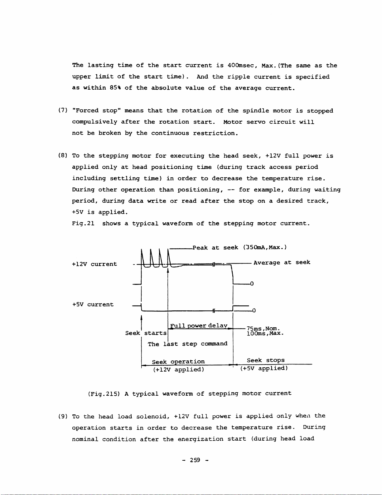
The
lasting
time
of
the
start
current
is
40Omsec,
Max.
(The
same
as
the
upper
as
(7)
"Forced
compulsively
not
(8)
To
applied
including
During
period,
+5v
Fig.2l
limit
within
be
the
is
of
the
85'
of
the
stopft
broken
stepping
only
other
during
applied.
shows a typical
means
after
by
at
settling
operation
the
motor
head
data
start
absolute
that
the
rotation
continuous
for
positioning
time)
than
write
waveform
time).
value
the
rotation
executing
in
order
positioning,
or
read
------Peak
And
the
of
the
of
start.
restriction.
the
time
of
to
after
the
(during
decrease
at
ripple
average
the
Motor
head
--
for
the
stop
stepping
seek
current
current.
spindie
servo
seek,
track
the
example,
(JSOmA,Max.)
motor
circuit
+12V
access
temperature
on a desired
motor
is
specified
is
full
per
during
current.
stopped
will
power
iod
rise.
track,
is
waiting
(9)
+12V
current
+5V
current
(Fig.2l5)
To
the
operation
nominal
head
starts
condition
Average
at
seek
JlLl~C~"'L
I I 0
Seek
A
load
I
starts
The
typical
solenoid,
in
order
after
~~~~~~~~~~---75ms,Nom.
lOOms,Max.
last
Seek 0 eration
(+12V
waveform
the
step
applied)
+12V
to
full
decrease
energization
command
of
stepping
power
the
start
Seek
(+5V
applied)
motor
is
applied
temperature
(during
stops
current
only
rise.
head
when
During
load
the
-
259
-
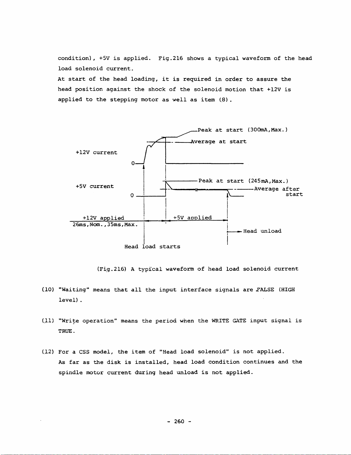
condition),
load
solenoid
At
start
of
+5V
current.
the
is
head
applied.
loading,
Fig.2l6
it
is
shows a typical
required
in
order
waveform
to
assure
of
the
the
head
head
position
applied
to
the
+l2V
+5V
26ms,Nom.,35ms,Max.
current
current
+l2V
against
stepping
applie<i
the
shock
motor
O~-~~--+j--
o
_i--_~J
of
the
solenoid
as
~
weIl
__
as
~~peak
~verage
I
-,r-----Peak
~----
__
~II.
__
item
~
____
at
at
at
I i
I
+5V
aoplied
Head
load
• ' • • i
starts
motion
(ß).
start
start
start
~-----Average
~
that
+l2V
(300mA,Max.)
(245mA,Max.)
is
after
start
I
i
~
Head
unload
I
(lO)
Lll)
e12)
"Waiting"
level)
"Write
TRUE.
For
a CSS
As
far
spindle
(Fi.g.216)
means
.
operation"
model,
as
the
motor
that
means
the
disk
current
A
all
item
is
typfcal
the
the
of
installed,
during
waveform
input
period
"Head
head
-
interface
when
load
head
unload
260
of
the
solenoid"
load
-
head
signals
w""RITE
condition
is
not
load
GATE
is
applied.
solenoid
are
..FALSE
input
not
applied.
continues
current
(HIGH
signal
and
is
the

2-4-3.
Current
Consumption
Timing
Chart
Fig.217
Fig.218
shows
shows
the
the
timing
timing
chart
chart
of
of
the
the
typica1
maximum
average
average
current
current
consumption.
consumption.
-
261
-

35ms,Max.
*60Oms,Max.
40Oms,
+12V
+5V
o
MaX
40
225
0--~--+-------~---+--~~------4+----~--~--~--~-------+-4------
powlr
on
surge
Motor
I
10Oms,Max.
620
1
230
MOts°t"art
on
60
Disk
insertion
Head
-I
530
load
Seek
'I
355
I 1
Seek
start
40Oms,Max.
l,lOOms,MaXo
1
230
H
ad
unload
Wrl.te
225
Jtor
off
Head
Mo
or
load
620
"I
275
Motor
start
on
530
I
Head
command
load
Notes:
1.
The
operation.
Average
2.
~Jpical
consumption
with
typical
3.
*:
condition
4.
Dotted
(Fig.217)
figures
nominal
Head
current
average
one
loading
(refer
line
Typical
show
the
current
measured
voltage.
obtained
is
to
shows
average
typical
lfffiiEIH1
with
Rotation
by a commercially
executed
item
the
case
current
-
~
means
a
1-8-3
of
262
average
typical
after
-
Ripple
practical
torque
the
of
FD-55
CSS
model.
timing
current
current
value
FDD
in
is
available
FDD
Specification)~
chart
(mA)
caused
of
room
supposed
becomes
at
average
temperature
disko
pre-ready
to
each
by
spindle
motor
current
be
a
and

3Oms, Max
lOOms
,Maxoll
.•
I '
i
•
40Oms,Max.
*600ms,Max.
10Oms,Max.
500
315
Head
unload
Write
300
Motor
off
Motor
Head
;-----
Motor
on
load
....
start
Head
command
450
Seele
start
-I
630
I
11
+12V
0--~--~--------~--~---+~-4----~~--~--4---~---4--------~-+~-+---
300
+5V
on
Motor
start
on
1
Power
surge
Motor
3151
110
I
i
1
I
I
I
Disk
insertion
Head
Seek
load
850
--+~
load
Notes:
1.
The
operation.
2.
The
the
some
specification,
3.
Refer
(Fig.218)
figures
actual
"maximum
abnormal
to
Notes
show
average
average"
conditions
or
1,
Maximum
the
value
forced
3,
maximum
of
'\Inder
such
stop
and 4 in
average
-
263
average
current
any
operating
as
of
Fig.217.
current
-
current
consumption
installing
the
spindle
timing
(mA)
does
conditions
a
disk
motor.
chart
at
of
each
not
except
out
exceed
for
of
2-5.
WRITE/REAO
The
FOO
has
METHOO
been
designed
for
excellent
stability
and
easily
handled
recording
Improved
electrical
compatibility
flexible
disk,
Improvements
(LSV,
track
against
bit
ation
ISV) , head
positioning,
inductive
shifts,
of
the
positioning,
and
environmental
dust,
to
t~mperature,
the
reliability
in
both
with
cover
improved
FOD
PLO
FM
(single
and
ISO,
assures
many
magnetic
optimized
noise,
signal-to-noise
controller
(or
VFO)
considerations
humidity,
of
density)
mechanical
ECMA,
a
better
ANSI,
areas,
characteristics,
~Tite/read
el~ination
parameters,
response
vibration
the
system
and
characteristics
and
error
margin.
including
of
ratio
speed,
such
as
as a whole.
MFM
JIS
disk
head-disk
circuitry,
spindle
and
such
optimbm
inductive
and
so
(double
standards
rotational
motor
so
as
the
write
on
also
density)
together
for
contact,
improved
noise,
on.
Careful
data
noise,
contribute
modes.
with
l30mm
speed
the
(5.25
accuracy
improved
shielding
reduction
consider-
separator
window
pre-compensation
po~~r
line
greatly
data
inches)
in
noise,
-
264
-

2-5-1.
Single
FM
method
The
FDO
recording.
The
FM
data
density
Density
is
has
method
generally
been
designed
utilizes
to
flux
used
to
two
frequency
transition
for
use
single
the
density
density
FM
method
components
ratio
recording.
for
single
(lF
is
0.5,
and
2F)
giving
density
and
a
the
redundancy
of
for
Sununary
(1)
Data
(2)
Clock
gaps,
FD-55A ~ F
bit
Bit
cells
WRITE/READ
FDD
Data
window
bit
and
of
(0)
DATA
ratio
ID
FM
is
(C)
2F(4lls)
of
field
and
method
located
is
located
0.5,
(track
50KHz
lt
1
C
without
for
in
the
at
0
(50%
taking
formatting).
FO-55G.
center
the
leading
0
C
c
I
I
tl
6lls
(75%
of
t2
4us
of
data
of
0
C
I
data
cycle)
cycle)
into
consideration
Data
the
bit
edge
of
1
D D C
I
transfer
cello
the
1 1
D C
I I I
I
I •
bit
rate
cello
0
I
I
C D C
I
the
1
I
Bit
lF
necessity
is
125KHz
0
I
cell
(8lls)
C
I
Note:
(Fig.219)
A
PLO
the
FDD
The
above
a
half
of
Bit
circuit
and a fixed
timings
the
correspondance
is
not
(llS)
indicated
necessary
window
can
are
values.
and
when
be
-
265
for
FD-55A
data
only
adopted.
-
window
the
'\..
in
FM
The
F.
FM
method
most
Timings
method
appropriate
is
for
FD-55G
adopted
are
with
window

is
6Us
for
tl
and
4Us
for
t2
in
the
figure
above.
The
t2
width
may
be
wider
window
provided
(towards
that
the
it
left
is
in
widened
the
in
figure
the
above).
trigger
pulse
direction
of
the
-
266
-

2-5-2.
Double
MFM
method
been
M2FM
Density
designed
method
is
generally
to
and
use
GeR
used
the
method
MFM
do
for
double
method
not
for
match
density
double
the
standard
recording.
density
recording.
model
of
The
the
FDD
FDD.
has
(1)
(2)
(a)
eliminating
By
the
da
density
with
the
great
The
MFM
data
density
without
(track
500KHz
Summary
Data
bit
Clock
following
No
data
ta
density
on
the
addition
increased
method
taking
formatting).
for
FD-55G.
of
MFM
(0)
bit
(C)
two
bit
the
to
disko
of
in
has
to
flux
into
method:
is
located
is
located
conditions
has
been
redundancy
be
doubled
FDD
controller
PLO
circuit,
the
recording
three
frequency
transition
consideration
Data
transfer
at
at
are
written
of
the
the
satisfied:
the
FM
without
increasing
will
hut
this
capacity.
~omponents,
density
the
necessity
rate
center
of
leading
in
the
praceding
method,
necessarily
is
ratio
is
250KHz
the
edge
the
MFM
the
compensated
lF,
4/3F
is
1
(redundancy
of
gaps
for
bit
cello
of a bit
bit
c~ll.
method
flux
be
and
more
enables
transition
compricated
for
by
2F.
the
The
:0)
and
ID
field
FD-55A ~ Fand
cell
when
the
(b)
No
In
the
not
Phase
window.
The
The
pulse
transitions.
data
MFM
always
locked
most
phase
from
bit
will
metnod,
necessary
oscillator
appropriate
shall
the
be
FDD
be
written
a
clock
as
window
locked
locates
the
(PLO)
so
bit
clock
is
that
at
-
in
at
is
l~s
the
267
the
the
will
used
for
the
center
-
present
leading
be
to
generate
tl
leading
between
hit
cello
·edge
regenerated
and
2~s
edge
two
of
the
for
of
each
in
clock
t2
the
data
bit
the
and
in
Fig.220.
READ
window
cell
FOO
is
controlle
data
DATA

Bit
cells
1
o o
o
I 1 I
Bit
1
cell
1
(4l.Js)
o
1 o
MFM
FDD
MFM
Note:
(Fig.220)
Lt
possible
therefore
by
WRITE/READ
data
window
4/3F
The
above
a
half
of
Bit
is
important
to
necessary
the
read
(6
s)
timings
the
indicated
correspondance
for
the
obtain
output
the
that
peak
D
(50%
(JJs)
PLO
widest
the
shift
t2
of
are
values.
and
circuit
window
PLO
(2lJs)
data
for
data
does
from
tl
I
cycle)
FO-55A ~ F.
window
to
generate
margin
the
not
magnetic
for
respond
in
D D
D
Timings
the
an
accurate
data
to
head.
2F
(4Us)
MFM
reading.
bit
It
for
method
window
shift
must
FO-55G
It
caused
be
are
as
is
designed
during
field.
Write
method
effectively.
bit
opposite
However,
on
appropriate
each
effects
several
pre-compensation
for
pattern,
the
overall
FDD
to
respond
the
direction
the
degree
value
and
such
slowly
synchronizing
bit
shift
Since
the
disko
as
the
position
in
of
frequency
of
Large
an
increase
so
is
generally
which
direction
of
anticipation.
bi~
shift
characteristics
write
pre-compensation
pre-compensation
that
bytes
contributes
the
in
bit
-
268
the
at
used
of
flux
during
shift
-
data
the
as
bit
shift
transition
read
of
at
window
head
the
to
the
should
value
the
will
of
10
active
the
window
can
can
operation
FOD
results
outer
field
compensation
be
predicted
be
depends
system
be
determined
tracks,
be
phase-locked
or
margin
shifted
and
in
undesirable
data
by
the
in
the
largely
the
most
for
decrease

in
read'
output
and a poorer
SjN
ratio
due
to
the
increased
use
of
the
bandwidth.
From
these
reduced
minimum
The
simplest
FOO
has
margin
When
less
not
you
than
to
Disk
considerations
by
increasing
of
write
been
in
this
use
±250nsec
cause
interchangeability
pre-compensation
solution
designed
way_
the
write
for
the
undesirable
it
will
the
frequency
is
to
per
form
to
provide
reliability
pre-compensation,
FD-55A ~ Fand
effect
suffers
be
seen
characteristics
shoulä
no
be
write
be
less
by
over
as a result.
that
bit
shift
used.
pre-compensation
and
sufficiently
careful
than±62.5nsec
compensation.
of
to
the
use
should
FOO
the
for
be
and
the
and
the
wide
window
value
FD-55G,
-
269
-

7733
TEAC
Corporation of America
Telegraph
Rd.,
[213]
726-0303
Montebello, CA
90640
 Loading...