How it Works
Log In / Sign Up
Buy Points
How it Works
FAQ
Contact Us
Questions and Suggestions
Users
TEAC
Loading...
A
AD600
2
AD-RW900
6
AG-1000
2
AG-10-D
3
AG-10DAV
AG15D
3
AG20D
AG2700
2
AG-3000
AG-360
AG-370
4
AG370 rec
AG-55
AG5700
AG5D
3
AG6000
AG-6500
AG-680
2
AG7000
AG-790
5
AG-790A
3
AG790E
AG-7D
4
AG-980
2
AG-D200
5
AG-D2000
AG-D200-B
AG-D500
3
AG-D500-B
AG-D7900
3
AG-D8000
2
AGD8800
3
AG-D8850
AGD-8900
AGD-9260
AGD 9300
AG-H300
4
AG-H300-Mk3
2
AG-H300mkII
AG-H300mkIII
2
AGH300MKll
AGH300MKlll
AG-H350
4
AG-H380
4
AG-H380DAB
2
AGH-500
AGH550
5
AG-H600
2
AG-H600DNT
2
AG H600NT
9
AG-H600NTZ
AG-L800
2
AG-V1020
AGV1050
AGV-3020
AGV6200
AGV7700
AG-V8060
2
AG-V8500
2
AG-V8520
AH-300
2
AH300II
AH-300 Mk2
AH-380
3
AH-400
AH-500
2
AH-500-I
AI-1000
2
AI-101DA
2
AI-2000
AI-3000
2
AI-301DA
8
AI-301DA-B
AI-301DA-X
3
AI-501DA
3
AI-503
3
AI-S01DA
AL-220S
2
AL-220U
AL-550S
2
AL-700
AL-700-P
3
AL-DK-5000S
AN-180
2
AN-300
3
AN-60
AN-80
AP1132
AP-150
AP220N
2
AP-505
AP-505 black
AP-505 silver
AP-55
2
AP-55 DiscAthlon 2
2
AQ-VU
AR-600
2
AR-650
5
AS-100
ASM-30
Loading...
Loading...
Nothing found
AGD-9260
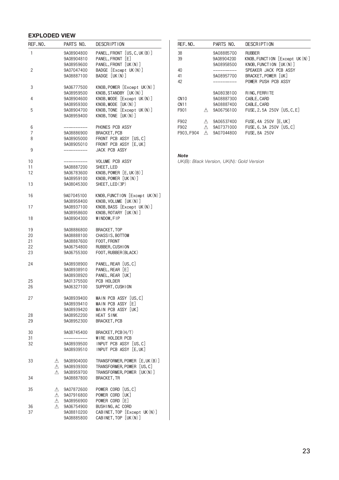
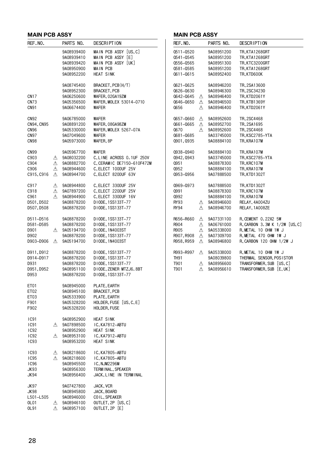
Service manual
32 pgs
4.34 Mb
1
Table of contents
Loading...
TEAC AGD-9260 Service manual
...
TEAC Service manual
Download
Specifications and Main Features
Frequently Asked Questions
User Manual
Download
Loading...
+
hidden pages
Unhide
You need points to download manuals.
1 point = 1 manual.
You can buy points or you can get point for every manual you upload.
Buy points
Upload your manuals
 Loading...