

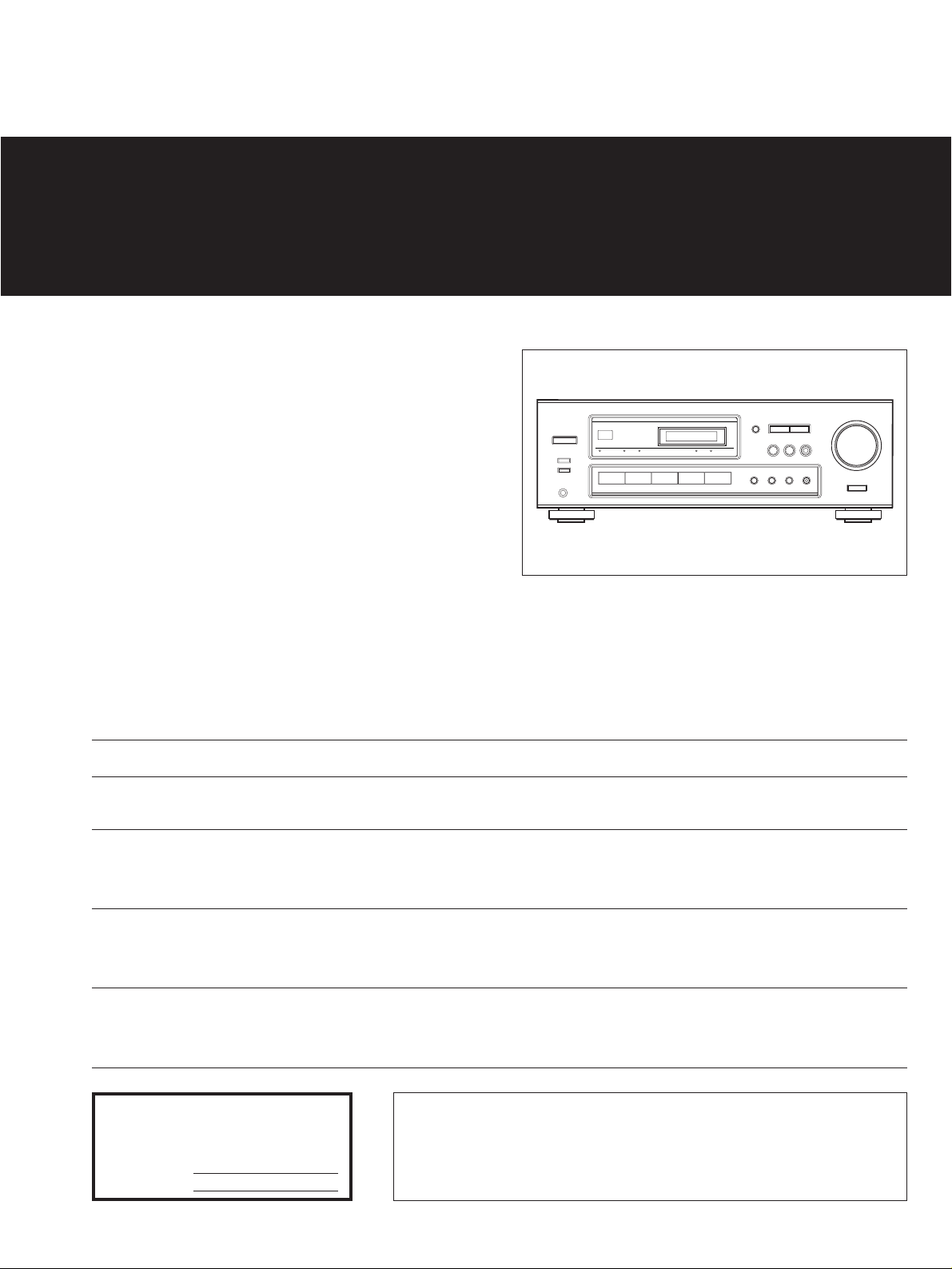
ag-680
`
AM/FM Stereo Receiver
9A07126800
This appliance has a serial number located
on the rear panel. Please record the model
number and serial number and retain them
for your records.
Model number
Serial number
WARNING: TO PREVENT FIRE OR SHOCK
HAZARD, DO NOT EXPOSE THIS
APPLIANCE TO RAIN OR MOISTURE.
The exclamation point within an equilateral triangle is intended to alert the user to the presence of important operating and maintenance (servicing) instructions in the literature
accompanying the appliance.
The lightning flash with arrowhead symbol, within an equilateral triangle, is intended to alert
the user to the presence of uninsulated “dangerous voltage” within the product’s enclosure
that may be of sufficient magnitude to constitute a risk of electric shock to persons.
CAUTION: TO REDUCE THE RISK OF ELECTRIC SHOCK, DO NOT
REMOVE COVER (OR BACK). NO USER-SERVICEABLE PARTS INSIDE.
REFER SERVICING TO QUALIFIED SERVICE PERSONNEL.
Ü
ÿ
Ÿ
Thanks for buying a TEAC. Read this manual carefully to get the best performance from this unit.
Nous vous remercions pour l’achat d’un appareil TEAC.
Lire ce manuel avec attention pour obtenir les meilleures performances possibles de cet appareil.
OWNER’S MANUAL........................................... 3
MANUEL DUPROPRIETAIRE......................... 19
– 2 –
IMPORTANT SAFETY INSTRUCTIONS
CAUTION:
• Read all of these Instructions.
• Save these Instructions for later use.
• Follow all Warnings and Instructions marked on the audio
equipment.
1) Read Instructions
— All the safety and operating instructions
should be read before the product is operated.
2) Retain Instructions — The safety and operating instructions
should be retained for future reference.
3) Heed Warnings — All warnings on the product and in the operating instructions should be adhered to.
4) Follow Instructions — All operating and use instructions should
be followed.
5) Cleaning — Unplug this product from the wall outlet before
cleaning. Do not use liquid cleaners or aerosol cleaners. Use a damp
cloth for cleaning.
6) Attachments — Do not use attachments not recommended by
the product manufacturer as they may cause hazards.
7) Water and Moisture — Do not use this product near water _for
example, near a bath tub, wash bowl, kitchen sink, or laundry tub; in
a wet basement; or near a swimming pool; and the like.
8) Accessories — Do not place this product on an unstable cart,
stand, tripod, bracket, or table. The product may fall, causing serious
injury to a child or adult, and serious damage to the product. Use
only with a cart, stand, tripod, bracket, or table recommended by the
manufacturer, or sold with the product. Any mounting of the product
should follow the manufacturer’s instructions, and should use a
mounting accessory recommended by the manufacturer.
9) A product and cart combination should be moved with care.
Quick stops, excessive force, and uneven surfaces may cause the
product and cart combination to overturn.
"Note to CATV system installer:
This reminder is provided to call the CATV system installer’s attention to Section 820-40 of the NEC which provides guidelines for
proper grounding and, in particular, specifies that the cable ground
shall be connected to the grounding system of the building, as close
to the point of cable entry as practical."
15) Lightning — For added protection for this product during a lightning storm, or when it is left unattended and unused for long periods
of time, unplug it from the wall outlet and disconnect the antenna or
cable system. This will prevent damage to the product due to lightning and power-line surges.
16) Power Lines — An outside antenna system should not be located in the vicinity of overhead power lines or other electric light or
power circuits, or where it can fall into such power lines or circuits.
When installing an outside antenna system, extreme care should be
taken to keep from touching such power lines or circuits as contact
with them might be fatal.
17) Overloading — Do not overload wall outlets, extension cords, or
integral convenience receptacles as this can result in risk of fire or
electric shock.
18) Object and Liquid Entry — Never push objects of any kind into
this product through openings as they may touch dangerous voltage
points or short-out parts that could result in a fire or electric shock.
Never spill liquid of any kind on the product.
19) Servicing — Do not attempt to service this product yourself as
opening or removing covers may expose you to dangerous voltage
or other hazards. Refer all servicing to qualified service personnel.
20) Damage Requiring Service — Unplug this product from the
wall outlet and refer servicing to qualified service personnel under
the following conditions:
a) when the power-supply cord or plug is damaged.
b) if liquid has been spilled, or objects have fallen into the product.
c) if the product has been exposed to rain or water.
d) if the product does not operate normally by following the operat-
ing instructions. Adjust only those controls that are covered by the
operating instructions as an improper adjustment of other controls
may result in damage and will often require extensive work by a qualified technician to restore the product to its normal operation.
e) if the product has been dropped or damaged in any way.
f ) when the product exhibits a distinct change in performance _ this
indicates a need for service.
21) Replacement Parts — When replacement parts are required,
be sure the service technician has used replacement parts specified
by the manufacturer or have the same characteristics as the original
part. Unauthorized substitutions may result in fire, electric shock, or
other hazards.
22) Safety Check — Upon completion of any service or repairs to
this product, ask the service technician to perform safety checks to
determine that the product is in proper operating condition.
23) Wall or Ceiling Mounting — The product should be mounted to
a wall or ceiling only as recommended by the manufacturer.
24) Heat — The product should be situated away from heat sources
such as radiators, heat registers, stoves, or other products (including amplifiers) that produce heat.
10) Ventilation — Slots and openings in the cabinet are provided
for ventilation and to ensure reliable operation of the product and to
protect it from overheating, and these openings must not be blocked
or covered. The openings should never be blocked by placing the
product on a bed, sofa, rug, or other similar surface. This product
should not be placed in a built-in installation such as a bookcase or
rack unless proper ventilation is provided or the manufacturer’s
instructions have been adhered to.
11) Power Sources — This product should be operated only from
the type of power source indicated on the marking label. If you are
not sure of the type of power supply to your home, consult your product dealer or local power company. For products intended to operate from battery power, or other sources, refer to the operating
instructions.
12) Grounding or Polarization — This product may be equipped
with a polarized alternating-current line plug (a plug having one
blade wider than the other). This plug will fit into the power outlet
only one way. This is a safety feature. If you are unable to insert the
plug fully into the outlet, try reversing the plug. If the plug should still
fail to fit, contact your electrician to replace your obsolete outlet. Do
not defeat the safety purpose of the polarized plug.
13) Power-Cord Protection — Power-supply cords should be routed so that they are not likely to be walked on or pinched by items
placed upon or against them, paying particular attention to cords at
plugs, convenience receptacles, and the point where they exit from
the product.
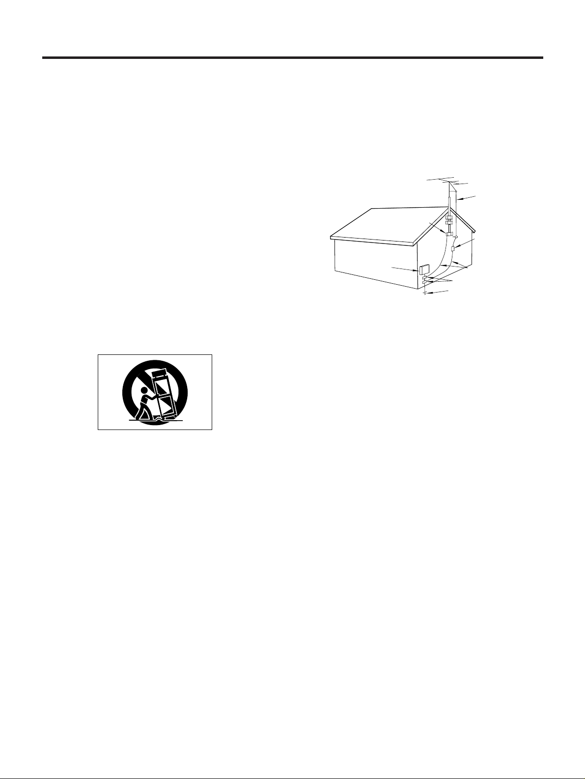
14) Outdoor Antenna Grounding — If an outside antenna or
cable system is connected to the product, be sure the antenna or
cable system is grounded so as to provide some protection against
voltage surges and built-up static charges. Article 810 of the
National Electrical Code, ANSI/NFPA 70, provides information with
regard to proper grounding of the mast and supporting structure,
grounding of the lead-in wire to an antenna discharge unit, size of
grounding conductors, location of antenna-discharge unit,
connection to grounding electrodes, and requirements for the
grounding electrode.
Example of Antenna Grounding as per
National Electrical Code, ANSI/NFPA 70
ANTENNA
LEAD IN
WIRE
GROUND
CLAMP
ANTENNA
DISCHARGE UNIT
(NEC SECTION 810-20)
ELECTRIC
SERVICE
EQUIPMENT
NEC - NATIONAL ELECTRICAL CODE
GROUNDING CONDUCTORS
(NEC SECTION 810-21)
GROUND CLAMPS
POWER SERVICE GROUNDING
ELECTRODE SYSTEM
(NEC ART 250. PART H)

– 3 –
CONTENTS
IMPORTANT SAFETY INSTRUCTIONS..................................................................................................................2
PRECAUTIONS .........................................................................................................................................................4
Read This Before Operating ...............................................................................................................................4
CONNECTIONS ........................................................................................................................................................5
System Connections ...........................................................................................................................................5
Antenna Connections..........................................................................................................................................6
FM Indoor Antenna.........................................................................................................................................6
FM Outdoor Antenna......................................................................................................................................6
AM Antenna ....................................................................................................................................................6
Speaker Connections ..........................................................................................................................................7
Power Cord ..........................................................................................................................................................7
AC OUTLET......................................................................................................................................................7
CONTROLS AND INDICATORS...............................................................................................................................8
REMOTE CONTROL UNIT .....................................................................................................................................10
Using the Remote Control Unit........................................................................................................................10
Battery Installation ............................................................................................................................................10
AUDIO OPERATIONS.............................................................................................................................................11
Back-up Memory Function ...............................................................................................................................11
Sleep Timer Operation......................................................................................................................................11
Basic Operations ...............................................................................................................................................11
Audio Adjustments.......................................................................................................................................12
Radio Reception ................................................................................................................................................12
Auto Tuning...................................................................................................................................................12
Manual Tuning..............................................................................................................................................13
Preset Tuning.....................................................................................................................................................13
Automatic Memory Presetting ....................................................................................................................13
Manual Memory Presetting .........................................................................................................................14
Listening to Records and Compact Discs .......................................................................................................14
Playing Tapes ....................................................................................................................................................14
Recording a Source...........................................................................................................................................15
When to Use Reset Switch ..........................................................................................................................15
TROUBLESHOOTING.............................................................................................................................................16
SPECIFICATIONS ...................................................................................................................................................17
– 4 –
TO THE USER
This equipment has been tested and found to
comply with the limits for a A/V receiver, pursuant
to Part 15 of the FCC Rules. These limits are
designed to provide reasonable protection against
interference in a residential area. This device
generates and uses radio frequency energy and if
not installed and used in accordance with the
instructions, it may cause interference to radio or
TV reception. If this unit does cause interference
with TV or radio reception you can try to correct
the interference by one or more of the following
measures:
a) Reorient or relocate the receiving antenna.
b) Increase the separation between the equip-
ment and the receiver.
c) Plug the equipment into a different outlet so
that it is not on the same circuit as the
receiver.
If necessary, consult the dealer or an experienced
radio/TV technician for additional suggestions.
CAUTION
Changes or modifications to this equipment not
expressly approved by TEAC CORPORATION for
compliance could void the user's authority to
operate this equipment.
For U.S.A.
The equipment draws nominal non-operating
power from the AC outlet with its POWER switch
in the STANDBY position.
Obs! nätströmställare ¨n skiljer ej hela apparaten
från nätet.
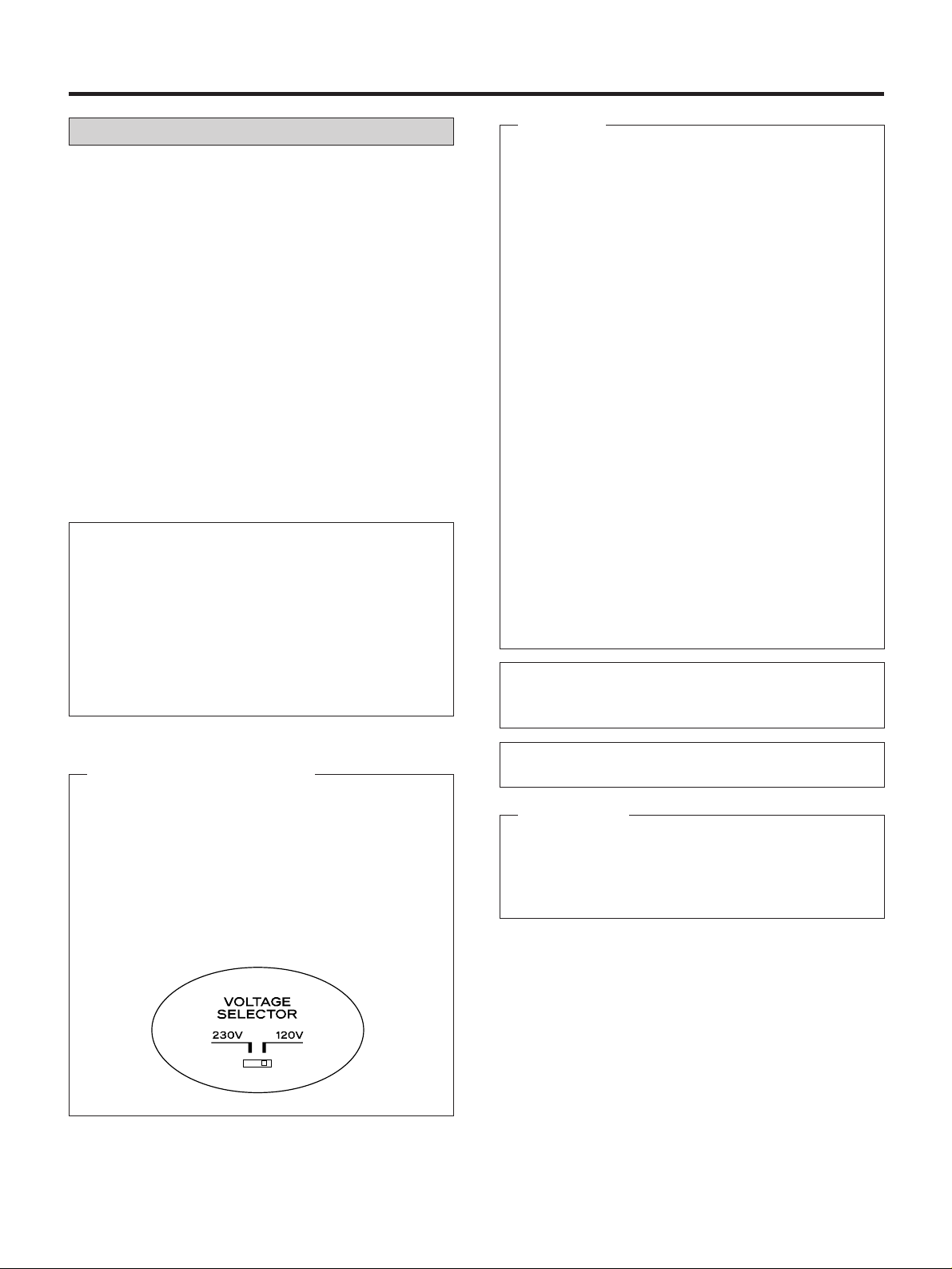
VOLTAGE CONVERSION
Be sure to remove the power cord from the AC
outlet before repositioning the voltage converter
switches.
1. Locate the voltage selector on the rear panel.
2. Using a flat-bladed screwdriver, set to the
appropriate 120 V or 230 V position according
to your area.
For General Export Models
AC POWER CORD CONNECTION
CAUTION:
TO PREVENT ELECTRIC SHOCK, MATCH WIDE
BLADE OF PLUG TO WIDE SLOT, FULLY INSERT.
For CANADA
● Choose the installation location of your unit carefully.
Avoid placing it in direct sunlight or close to a source
of heat. Also avoid locations subject to vibrations and
excessive dust, heat, cold or moisture.
● The ventilation holes should not be covered. Make
sure there is at least 50 cm (20 inches) of space
above and at least 10 cm (4 inches) of space beside
the amplifier/receiver. Do not place a CD player or
other equipment on top of the amplifier/receiver.
● Do not open the cabinet as this might result in
damage to the circuitry or electrical shock. If a
foreign object should get into the set, contact your
dealer.
● When removing the power plug from the wall outlet,
always pull directly on the plug, never yank the cord.
● Do not attempt to clean the unit with chemical
solvents as this might damage the finish. Use a
clean, dry cloth.
● Keep this manual in a safe place for future reference.
Read This Before Operating
CAUTION Regarding Placement
(Except for U.S.A. and Canada)
To maintain proper ventilation, be sure to leave a
space around the unit (from the largest outer
dimensions including projections) equal to, or
greater than, shown below.
Left and Right Panels : 10 cm
Rear Panel : 10 cm
Top Panel : 50 cm
– 5 –
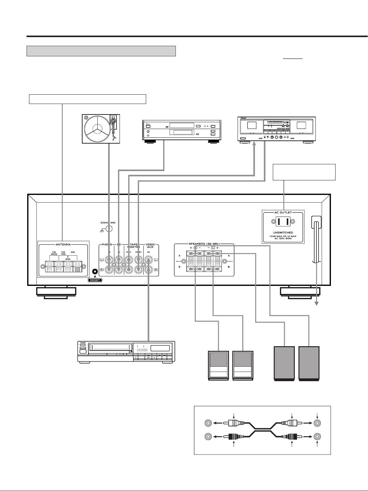
CONNECTIONS
System Connections
: Audio signal
CAUTION: Do not plug the power cord of any component
into AC outlets and do not turn their POWER switches
on until all connections have been performed.
Refer to "Antenna Connections" on pages 6.
Turntable
CD Player
Tape Deck
Speaker B
Speaker A
Audio connection cords
VIDEO 1
AC Outlet:
Unswitched, Total 100W.
To AC outlet
LINE IN
AUDIO OUT
LINE OUT
+
–
White
White White
Red Red Red
L
L
RR

– 6 –
AM Antenna
FM Outdoor Antenna
Antenna Connections
FM Indoor Antenna
AM Indoor Loop Antenna
A high-performance AM loop antenna provided with the
receiver is sufficient for good reception in most areas.
Connect the loop antenna's wires to the AM antenna
terminals as shown. Place the antenna on a shelf, for
example, or hang it on a window frame, etc., in the
direction which gives the best reception, as far away as
possible from the entire system, speaker cords and the
power cord, to prevent unwanted noise.
AM Outdoor Antenna
If the AM loop antenna provided does not deliver
sufficient reception (because you are too far from the
transmitter or in a concrete building, etc.), it may be
necessary to use an outdoor AM antenna. Use an
insulated wire more than 15 ft (5 m) long, strip one end,
and connect this to the terminal as shown. The antenna
wire should be strung outdoors or indoors near a
window. For better reception, connect the GND terminal
to a reliable ground.
Note: Even when using an outdoor AM antenna, do not
disconnect the AM loop antenna.
In an area where FM signals are weak, it will be
necessary to use a 75-ohm unbalanced-type outdoor FM
antenna. Generally, a 3-element antenna will be
sufficient; if you live in an area where the FM signals are
particularly weak, it may be necessary to use one with 5
or more elements.
A 75-ohm antenna uses a coaxial cable and should be
connected as follows: first strip the covering of the
cable, then twist the wire shielding so the inner core and
shielding can be connected as shown.
In an area with strong FM signals, the "T"-type FM
antenna provided is sufficient. Extend this into a "T"
shape and connect the two wires at the base of the T to
the antenna terminals, as shown. For details of how to
connect the antenna wires to the terminals, see the
illustration.
Extend the top of the T and fix with thumb tacks, or the
like, to a wall or window frame for the best possible
reception.
Press the lever, insert the
stripped and twisted end of the
wire, then release the lever so
that the wire is held securely.
How to connect antenna
"T"-type FM Antenna
(300Ω)(provided)
Outdoor FM Antenna (75Ω)
AM Loop Antenna
(provided)
U.S.A/Canada/
General Export
Model
AM Outdoor
Antenna
– 7 –
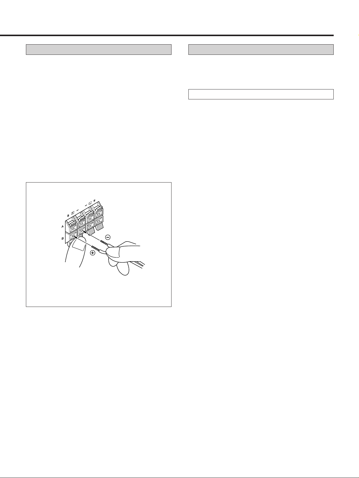
Speaker Connections Power Cord
AC OUTLET
Caution:
To avoid damaging the speakers by inputting a
sudden high-level signal, be sure to switch the power
off before connecting the speakers.
Connect each speaker to the corresponding speaker
terminals, as desired.
Notes:
● When attaching speakers, be sure to connect them to
both channels (L and R).
If speakers are connected to only A or B, no sound
will be heard from them if both SPEAKERS “A” and
“B” are selected.
● Use speakers with a nominal impedance of 8 ohms
or more.
How to connect the speaker cords
Press the lever, insert the stripped and twisted
end (approx. 10 mm) of the cord, then release
the lever so that the cord is held securely.
Be sure to connect the power cord to an AC outlet which
supplies the correct voltage, as set by the voltage
selector.
UNSWITCHED:
This socket does not switch off when the amplifier is
turned off.
Caution:
The total power consumption of the components connected to the AC OUTLET must not exceed 100W.
– 8 –
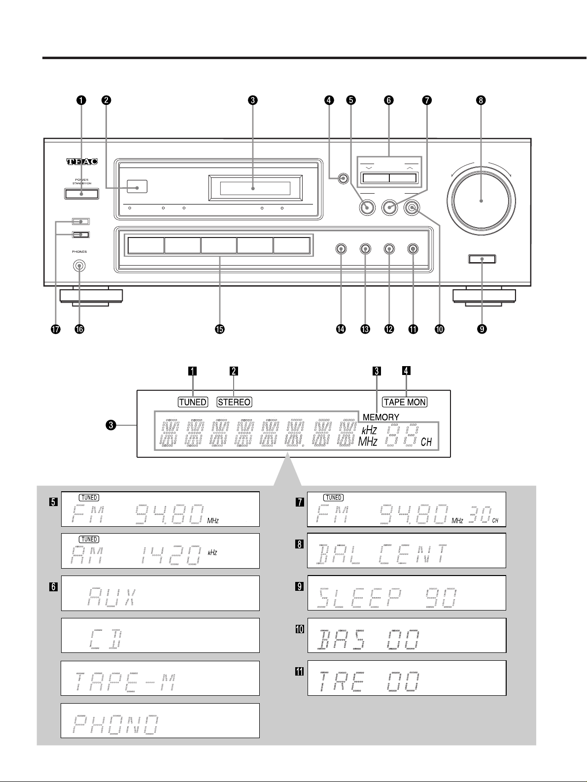
CONTROLS AND INDICATORS
Front Panel
TUNER
30FM/30 AM RANDOM STATION PRESETS
PHONO
CDTAPE MONITORVIDEO/AUX
SPEAKERS
SPEAKERSA
B
MEMORY
BAND
TUNING
MODE
FM MODE
SLEEP
STANDBY
LOUDNESS
REMOTE
SENSOR
JOG CONTROL
TUNING/PRESET
BASS
DOWN UP
JOG
VOLUME
DOWN
LEFT
RIGHT
UP
LOUDNESS
TREBLE
BALANCE
MUTE
– 9 –
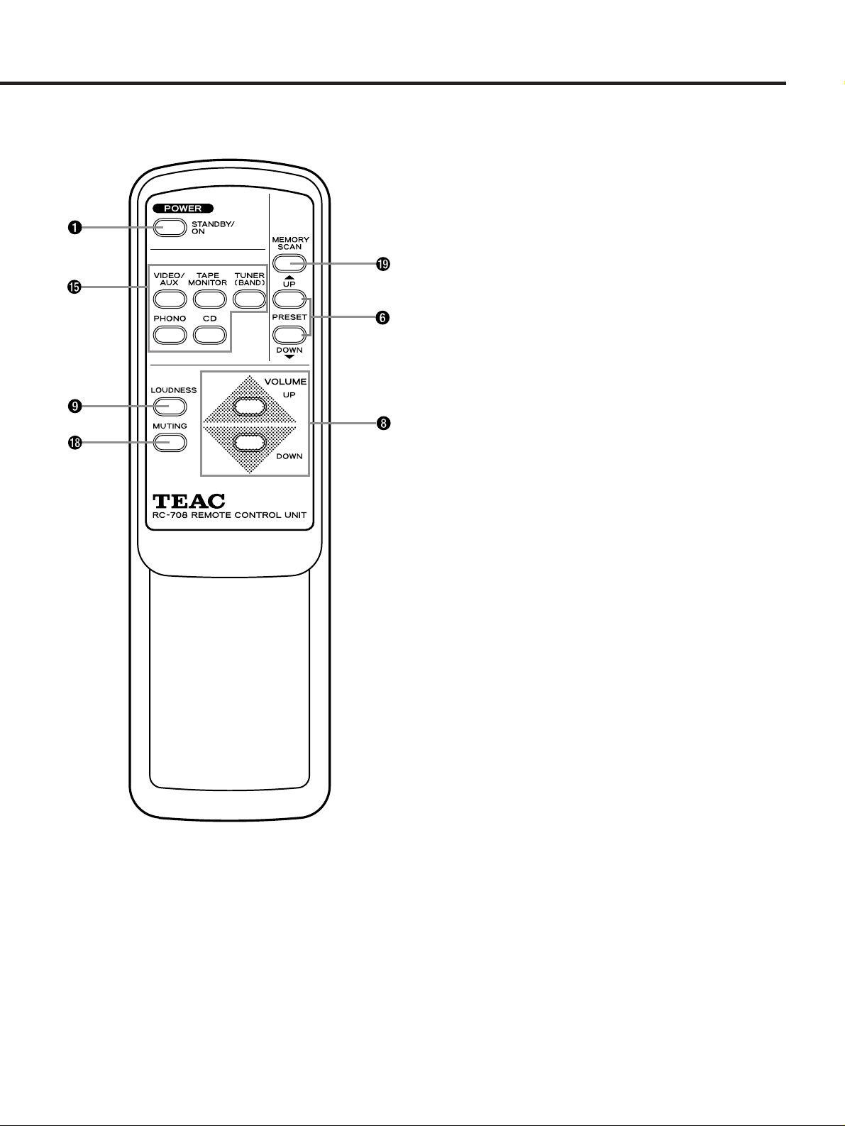
Remote Control Unit
1 POWER STANDBY/ON Button
2 REMOTE SENSOR Window
3 Multi-Function Display
4 TUNING MODE Button
5 BASS Button
6 TUNING/PRESET Buttons
7 TREBLE Button
8 VOLUME Control/JOG dial
9 LOUDNESS Button
0 BALANCE Button
q SLEEP Button
w MEMORY Button
e FM MODE Button
r BAND Selector Button
t Function Selector Buttons
y PHONES Jack
u SPEAKERS Select Buttons
i MUTING Button
o MEMORY SCAN Button
1 TUNED Indicator
2 STEREO Indicator
3 MEMORY Indicator
4 TAPE Monitor Indicator
5 BAND/FREQUENCY Display
6 Source Display
7 PRESET Channel Display
8 BALANCE Display
9 SLEEP Time Display
0 BASS Display
q TREBLE Display
Certain buttons on the remote control unit and on the
front panel of the receiver have the same or similar
functions and have the same reference numbers.
– 10 –
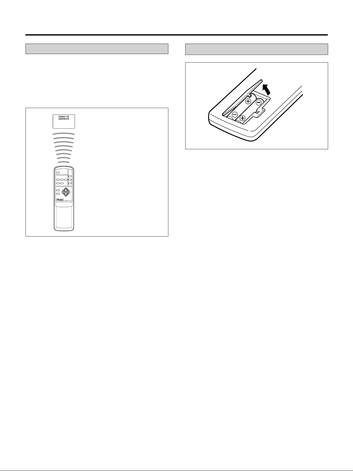
Using the Remote Control Unit Battery Installation
REMOTE CONTROL UNIT
1. Remove the battery compartment cover.
2. Insert two "AA" (R6, SUM-3) dry batteries.
Make sure that the batteries are inserted with their
positive
≠ and negative – poles positioned correctly.
3. Close the cover until it clicks.
Battery Replacement
If the distance required between the remote control unit
and main unit decreases, the batteries are exhausted. In
this case replace the batteries with new ones.
Precautions concerning batteries
● Be sure to insert the batteries with correct positive
"
≠" and negative "–" polarities.
● Use batteries of the same type. Never use different
types of batteries together.
● Rechargeable and non-rechargeable batteries can be
used. Refer to the precautions on their labels.
● When the remote control unit is not to be used for a
long time (more than a month), remove the batteries
from the remote control unit to prevent them from
leaking. If they leak, wipe away the liquid inside the
battery compartment and replace the batteries with
new ones.
● Do not heat or disassemble batteries and never
dispose of old batteries by throwing them in a fire.
By using the provided remote control unit, the
receiver and some other TEAC components used with
it can be controlled from your listening position.
To use the remote control unit, point it at the REMOTE
SENSOR window of the receiver (or other TEAC
component).
REMOTE SENSOR window
of the receiver or other
TEAC component
Notes:
● Even if the remote control unit is operated within the
effective range, remote control operation may be
impossible if there are any obstacles between the unit
and the remote control.
● If the remote control unit is operated near other
appliances which generate infrared rays, or if other
remote control devices using infrared rays are used
near the unit, it may operate incorrectly. Conversely,
the other appliances may operate incorrectly.

– 11 –
Back-up Memory Function
Sleep Timer Operation
Basic Operations
AUDIO OPERATIONS
BACK-UP Memory
This is the function which preserves the preset
memory and most-recent memory functions. In the
event of a power failure, or if the power cord of this
unit is disconnected from the electric outlet, the backup memory will preserve the preset memory and
most-recent memory functions for as long as
approximately 3 days.
To Prevent Erasing the Memory
If the power supply is interrupted for 3 days or longer,
the memory settings will be erased.
1. Press the POWER button to ON.
2. Select the desired source with the source selector
buttons.
3. To adjust the tone or the balance between the left
and right channels, press the BASS, TREBLE or
BALANCE button, then turn the JOG dial until the
desired level appears in the display.
4. Set the LOUDNESS button to the OFF position.
5. Select the speaker system to be used with the
SPEAKERS select buttons (speakers “A” and “B” can
also be selected simultaneously).
6. Start playing the source component.
7. Gradually turn up the volume to the required level
with the VOLUME control.
Note:
The following points apply throughout the
"AUDIO OPERATIONS" sections unless otherwise
noted.
● To simplify explanations, instructions refer to
names of buttons and controls on the front
panel, making no mention of the use of remote
control unit.
● To listen to a source other than tape deck, press
the TAPE MONITOR button to the OFF position
(the tape monitor indicator (TAPE MON) will not
light in the display).
SLEEP Timer Function
This function allows you to preprogram the
receiver to switch its own power off automatically.
You can then enjoy the audio system for a specified amount of time without having to worry
about turning the unit off later.
Each press of the SLEEP button changes the time
indication by 10 minutes.
∑ SLEEP 90 ∑ SLEEP 80 ∑
...
∑ SLEEP 10
(Released condition)ß
To let the remaining time (until power off) appear
on the display while the sleep timer is engaged,
press the SLEEP button once.
REMOTE
SENSOR

– 12 –
Audio Adjustments Radio Reception
Auto Tuning
1. Press the TUNER button*.
* The TUNER button can also be pressed instead
when you want to listen to a station selected last
by changing from another source.
2. Select the AM or FM by pressing the BAND selector
button.
3. Press the TUNING MODE button to change to
TUING mode. (The CH indicator disappears from
the display).
● This button is used to select Tuning or Preset mode.
4. Press the UP or DOWN TUNING/PRESET button
(within 0.5 to 2 seconds). The next station broadcasting at a frequency higher or lower than that of
the current station is automatically detected and
tuned in.
● By pressing and holding the TUNING/PRESET button
for longer than 2 seconds, it will continue to control.
POWER STANDBY/ ON Button
Press this button to turn the power on.
Press it again to turn the system off (power standby
mode).
The indicator lights up in power standby mode and
goes out when this unit is turned on.
SPEAKERS Select Buttons
These buttons are used to select speaker system A or B.
BASS/TREBLE Buttons
These two tone buttons – BASS and TREBLE – can be
used to obtain a "flat" frequency response or a tone
which suits your individual listening preference. The
BASS button adjusts low frequencies and the TREBLE
button adjusts the high frequencies.
BALANCE Button
This button is used to adjust the balance between the
left and right channels. Normally set to the center
position.
LOUDNESS Button
This button compensates for the non-linear response of
the human ear at low volumes. Set this switch to the
OFF position when listening at normal levels.
MUTING Button (on the Remote Control Unit)
Press this to mute (–20 dB) the sound from the speakers and headphones when answering the telephone,
etc.
To restore the original volume, press the MUTING
button again. While muting is engaged, the MUTE
indicator will flicker.
REMOTE
SENSOR
REMOTE
SENSOR
● FM MODE Button
Pressing this button alternates between Stereo
mode and Mono mode.
Stereo
FM stereo broadcasts are received in stereo and
the STEREO indicator lights in the display.
Monophonic broadcasts are received in mono.
Mono
To compensate for weak FM stereo reception,
select this mode. Reception will now be forced
monaural, reducing unwanted noise.
● TUNED Indicator
''TUNED'' appears in the display when a broadcast is correctly tuned in.

– 13 –
Manual Tuning
Manual Tuning is generally used to tune to stations
broadcasting a signal that is too weak to be received
by Auto Tuning.
1. Press the TUNER button.
2. Select the AM or FM by pressing the BAND selector
button.
3. Press the TUNING MODE button to change to
TUNING mode. (The CH indicator disappears
from the display).
4. When the UP or DOWN TUNING/PRESET button is
pressed momentarily (0.5 second or less), the
frequency changes by a fixed step (see STEPS
below).
STEPS
FM: 100-kHz steps
AM: 10-kHz steps
Preset Tuning
Automatic Memory Presetting
This facility is used to store FM, AM broadcasting from
Channel 1 to 30 respectively.
REMOTE
SENSOR
1. Press the TUNER button.
2. Select the AM or FM by pressing the BAND selector
button.
3. Press the MEMORY button for a while (for more than
1.5 seconds).
1 The start frequency will show in the display.
● 87.5 MHz in FM, 530 kHz in AM.
2 The frequency and display will automatically scan.
● 100 kHz steps for FM, 10 kHz steps for AM.
3 The frequency shown in the display will rapidly
change. As each station is located a preset
number will appear in the display indicating which
preset MEMORY button has been assigned to the
station located. The scanning process will continue to operate in this fashion until 30 stations have
been found and entered into the preset memory
or when there are no more stations to be found
on the waveband chosen. The memory indicator
will extinguish and let you hear the last station to
be memorized.
● To listen to the memorized station select the band
required and press the TUNING/PRESET buttons.
4. The last memorized channel of each band will be
displayed when Auto Memory is completed. Check
the programmed frequencies with TUNING/PRESET
UP, DOWN button.

– 14 –
Listening to Records and Compact Discs
Playing Tapes
Manual Memory Presetting
1. Press the PHONO or CD button.
2. Play the turntable (with a moving magnet cartridge)
or CD player.
1. Press the TUNER button.
2. Select the AM or FM by pressing the BAND selector
button.
3. Press the TUNING MODE button to change to
TUNING mode. (The CH indicator disappears
from the display).
4. Select the frequency you want to preset by pressing
UP or DOWN TUNING/PRESET button.
5. Press the MEMORY button briefly, MEMORY display
will blink at an interval of 1 second.
6. While the MEMORY indicator is lit, press the TUNING
/PRESET buttons to select the desired channel, then
press the MEMORY button again.
Using the Memory Scan Function
When the MEMORY SCAN button is pressed, the preset
channels in which frequencies in the band (AM or FM)
selected have been stored are scanned at 5-second
intervals. When you hear a broadcast you want to listen
to, release the Memory Scan function by pressing the
MEMORY SCAN button again.
"Back-up" Memory Function
This function conserves the already preset station memories, and "Most-recent" memory function, even in the
event of a cut-off of power supply, as when the plug is
pulled out of the wall outlet, for 3 days.
REMOTE
SENSOR
1
REMOTE
SENSOR
1. Set the TAPE MONITOR button to ON; the tape
monitor indicator (TAPE MON) will appear in the
display.
2. Operate tape deck for playback.
REMOTE
SENSOR

– 15 –
Recording a Source
Recording Program Source
You can record a program source such as a record or
Compact Disc onto a cassette deck connected to the
TAPE REC jacks.
REMOTE
SENSOR
1. Make sure the TAPE MONITOR button is set to OFF,
then press the source selector button corresponding
to the source to be recorded.
2. Play the source.
3. Operate the tape deck for recording.
Tape Monitoring
If the tape deck has separate record and playback
heads, during recording, the recorded sound can be
heard from the speakers with the TAPE MONITOR
button set to ON.
W
hen to UseReset
Switch
1. When this system is subjected to an electrical shock.
2. When the power is irregular.
In these cases, try the following (in power standby
mode):
Note: When the RESET switch is pressed, all the
memory will be canceled.
— Rear panel —
Press the RESET switch lightly once or twice with a
pencil or a ballpoint pen.

– 16 –
Problem Probable Cause Remedy
Amplifier
When listening to the music in stereo, Speakers are connected wrongly. After checking, if needed, connect correctly
left/right speakers sounds reversed. again.
Low hum or buzzer sound. Power line of fluorescent light is install- Place this product from electric devices
ed near to wall outlet of this product. as far away as possible.
Sound is only heard from one channel. One of the input cords is disconnected. Connect the input cords securely.
The JOG dial is set to one end. Adjust the JOG dial.
Sound cut during listening to the music Speaker impedance is less than After turning off the power and then turning
or no sound even though power is ON. prescribed for this unit. it on again, reduce the volume or change to
the regulated speakers.
Tuner
An unusual hissing noise is heard when A slight noise may be heard because O Try reducing the treble sound by turning
listening to the broadcast in stereo, the method use for modulation of FM the JOG dial.
but not heard when listening stereo broadcasts is different than that O Try changing the location, height and/or
monaurally. used for monaural broadcasts. direction of the antenna.
O Set the FM mode to monaural by pressing
Noise is excessive in both stereo and Poor location and/or direction of the the FM MODE button. (Note that the
monaural broadcasts. antenna. broadcast will then be heard as monaural
sound.)
Transmitting station is too far away. O If an indoor antenna is being used, change
to an outdoor antenna.
Sound is distorted and/or the volume Broadcast signals are being disturbed. O Try using an antenna with more elements.
level becomes low.
Excessive distortion in the sound of Speaker system connections are not
stereo broadcasts. correct.
Remote Control Unit
Remote control impossible. The batteries are exhausted. Replace with new batteries.
The remote control unit is too far from Operate the remote control unit within the
the receiver or out of the effective range. effective range.
TROUBLESHOOTING
To determine any problem with your receiver, always check the most obvious possible causes first. If any problem still
remains after you have checked the items below, consult your nearest TEAC dealer.

– 17 –
SPECIFICATIONS
Amplifier Section
Output Power (Front):
F.T.C. Rating:
100 watts RMS per channel minimum, both channels
driven into 8 ohms (40Hz-20kHz) with no more than 0.9
% total harmonic distortion (U.S.A./Canada)
RMS Power (40 Hz – 20 kHz):
100 watts/8 ohms, 0.9% (General Export)
Total Harmonic Distortion (Front):
0.02 % (at 100 watts, 1 kHz)
Input Sensitivity/Impedance:
PHONO: 2.5 mV/22 k ohms
LINE
*
: 220 mV/22 k ohms
Frequency Response:
PHONO: 20 Hz – 20 kHz, ±3 dB
LINE
*
: 20 Hz – 30 kHz, +1/ –3 dB
Signal-to-Noise Ratio:
PHONO: 70 dB (IHF-A)
LINE
*
: 90 dB (IHF-A)
Tone Control:
BASS: ± 9 dB at 100 Hz
TREBLE: ± 9 dB at 10 kHz
FM Tuner Section
(Without notes 100.1 MHz, 65 dBf)
Tuning Range:
87.5 MHz – 108.0 MHz (100 kHz steps)
(U.S.A./Canada/General Export)
Usable Sensitivity (IHF):
Mono: 15 dBf (U.S.A./Canada/General Export)
50 dB Quieting Sensitivity:
Mono: 23 dBf (U.S.A./Canada/General Export)
Stereo: 40 dBf (U.S.A./Canada/General Export)
Capture Ratio:
2.0 dB (U.S.A./Canada/General Export)
Image Rejection Ratio:
40 dB (U.S.A./Canada/General Export)
AM Suppression Ratio: 40 dB
Total Harmonic Distortion (1 kHz):
Mono: 0.4%
Stereo: 0.5%
Frequency Response: 30 Hz – 15 kHz, +1/ –1.5 dB
Stereo Separation (1 kHz): 40 dB
Signal-to-Noise Ratio:
Mono: 65 dB
Stereo: 60 dB
AM Tuner Section
Tuning Range:
530 kHz – 1,720 kHz (10 kHz steps)
(U.S.A./Canada/General Export)
Usable Sensitivity: 55 dB/m
Total Harmonic Distortion: 1.5% at 85 dB/m
Signal-to-Noise Ratio: 35 dB at 85 dB/m
General
Power Requirements:
120 V AC, 60 Hz (U.S.A./ Canada)
120/230 V AC, 50-60 Hz (General Export)
Power Consumption:
2.5 A (U.S.A./ Canada)
AC Outlets:
Unswitched ˆ 1, Total 100 W max. (1 A max.)
(U.S.A./Canada)
Unswitched
ˆ 1, 100 W max. (General Export)
Dimensions (W ˆ H ˆ D): 435 ˆ 130 ˆ 310 mm
Weight (net): 7.0 kg
Standard Accessories:
AM Loop Antenna ˆ 1
FM "T" Type Antenna
ˆ 1
Remote Control Unit (RC-708)
ˆ 1
*
LINE means CD, VIDEO/AUX and TAPE.
… Improvements may result in specifications and features
changing without notice.
… Illustrations may differ slightly from production models.

– 19 –
SOMMAIRE
AVANT UTILISATION............................................................................................................................................20
Lire ceci avant de faire fonctionner l'appareil ................................................................................................20
RACCORDEMENTS ................................................................................................................................................21
Raccordements de système .............................................................................................................................21
Raccordements d’antenne................................................................................................................................22
Antenne FM intérieure .................................................................................................................................22
Antenne FM extérieure.................................................................................................................................22
Antenne AM ..................................................................................................................................................22
Branchement des haut-parleurs.......................................................................................................................23
Cordon d'alimentation ......................................................................................................................................23
Prises CA (AC OUTLET)................................................................................................................................23
COMMANDES ET INDICATEURS .........................................................................................................................24
TÉLÉCOMMANDE ..................................................................................................................................................26
Utilisation de la télécommande .......................................................................................................................26
Mise en place des piles.....................................................................................................................................26
FONCTIONNEMENT AUDIO..................................................................................................................................27
Fonction de mémoire de soutien.....................................................................................................................27
Fonctionnement de la minuterie de sommeil ................................................................................................27
Fonctionnement de base ..................................................................................................................................27
Réglages audio..............................................................................................................................................28
Réception de la radio ........................................................................................................................................28
Syntonisation automatique..........................................................................................................................28
Syntonisation manuelle ...............................................................................................................................29
Syntonisation préréglée ...................................................................................................................................29
Préréglage automatique de la mémoire.....................................................................................................29
Préréglage manuel de la mémoire..............................................................................................................30
Ecoute de disques ou de disques audionumériques.....................................................................................30
Lecture de cassettes..........................................................................................................................................30
Enregistrement d'une source...........................................................................................................................31
Utilisation du commutateur de remise a zero ...........................................................................................31
EN CAS DE DIFFICULTÉS......................................................................................................................................32
CARACTÉRISTIQUES TECHNIQUES ....................................................................................................................33

– 20 –
AVANT UTILISATION
For U.S.A.
Pour les modèles d’exportation générale
Bien débrancher le cordon d’alimentation de la
prise secteur avant de repositionner le sélecteur
de changement de tension.
1. Localiser le sélecteur de tension sur le
panneau arrière.
2. En utilisant un tournevis à lame plate, régler
sur la position appropriée 120 V ou 230 V en
fonction de la tension locale.
CORDON DE CONNEXION CA
ATTENTION:
POUR ÉVITER LES CHOCS ÉLECTRIQUES,
INTRODUIRE LA LAME LA PLUS LARGE DE LA
FICHE DANS LA BORNE CORRESPONDANTE DE
LA PRISE ET POUSSER JUSQU’AU FOND.
Pour le CANADA
● Choisir avec soin l'endroit où vous placerez votre
appareil. Eviter de le placer directement au soleil ou
près d'une source de chaleur. Eviter aussi les
endroits sujets à des vibrations, à de la poussière
excessive, à la chaleur, au froid ou à l'humidité.
● Les trous de ventilation ne doivent pas être couverts.
S'assurer qu'il y a un espace d'au moins 50 cm au
dessus et d'au moins 10 cm à côté de l’amplificateur/
récepteur. Ne pas placer un lecteur CD ou un autre
appareil sur le dessus de l’amplificateur/récepteur.
● Ne pas ouvrir le coffret car ceci risquerait de
provoquer des dommages aux circuits ou des chocs
électriques. Si un objet rentre dans l'appareil,
contacter votre revendeur.
● Lors du débranchement du cordon d'alimentation de
la prise murale, toujours tirer sur la fiche et non sur
le cordon.
● Ne pas essayer de nettoyer l'appareil avec des
solvants chimiques car ceci pourrait endommager le
fini de l'appareil. Utiliser un chiffon propre et sec.
● Garder soigneusement ce manuel d'instructions
pour une référence ultérieure.
Lire ceci avant de faire fonctionner
l'appareil
Changement de tension

– 21 –
RACCORDEMENTS
Raccordements de système
: Signal audio
ATTENTION : Ne pas brancher le cordon d'alimentation de l'un des éléments de la
chaîne sur les sorties CA et ne pas mettre les commutateurs en position POWER
(MISE EN MARCHE) tant que tous les raccordements n'ont pas été effectués.
VIDEO 1
+
–
Se reporter à "Raccordements d'antenne" à la page 22.
Platine tournedisque
Lecteur de disque audionumérique
Platine à cassette
Entrée ligne
Sortie ligne
Prise secteur CA:
non commutées, total
100W ou 1A
Vers prise
secteur CA
Sortie audio
Haut-parleur B
Haut-parleur A
LL
RR
Blanc Blanc Blanc
Rouge Rouge Rouge
Cordons de raccordement audio

– 22 –
Antenne AM
Antenne FM extérieure
Raccordements d’antenne
Antenne FM intérieure
Antenne-cadre intérieure AM
L'antenne cadre AM haute performance, fournie avec le
récepteur permet une très bonne réception dans la
plupart des régions.
Raccorder les fils de l'antenne-cadre aux bornes
d'antenne AM comme décrit.
Placer l'antenne sur une étagère, par exemple, ou la
suspendre dans un encadrement de fenêtre, etc., en
l'orientant de façon à obtenir la meilleure réception
possible, et aussi loin que possible de la chaîne, des fils
de raccordement des haut-parleurs et du cordon
d'alimentation, afin d'éviter tout bruit indésirable.
Antenne extérieure AM
Si l'antenne cadre AM fournie ne permet pas une
réception satisfaisante (du fait que vous êtes situé trop
loin d'un émetteur ou que vous habitez dans un
bâtiment en béton, etc.), il peut être nécessaire d'utiliser
une antenne AM extérieure. Utilisez un fil isolé d'une
longueur supérieure à 5 m, dénudez l'une de ses
extrémités et raccordez la à la borne, comme décrit sur
le schéma. Le fil d'antenne doit être tendu à l'extérieur
ou à l'intérieur à proximité d'une fenêtre. Pour une
meilleure réception, raccordez la prise de terre à une
masse fiable.
Remarque: Même si vous utilisez une antenne
extérieure, ne débranchez pas l'antennecadre AM.
Dans une région où les signaux FM sont faibles, il sera
nécessaire d'utiliser une antenne FM extérieure
asymétrique 75 ohms. En général, une antenne à 3
éléments sera suffisante; si vous habitez dans une
région où les signaux FM sont particulièrement faibles,
il peut être nécessaire d'utiliser une antenne à 5
éléments ou plus.
Les antennes 75 ohms utilisent un câble coaxial et
doivent être raccordées comme suit: d'abord dénuder
le revêtement du câble, puis torsader le fil de blindage
pour que l'âme et le blindage puissent être raccordés
comme montré.
Dans une région avec des signaux FM puissants,
l'antenne de type "T" fournie est suffisante. L'étendre en
forme de "T" et brancher les deux fils à la base du "T"
aux bornes d'antenne comme montré. Pour des détails
sur la façon de raccorder les fils d'antenne aux bornes,
voir l'illustration.
Etendre le haut du "T" et le fixer avec des punaises, etc.
à un mur ou un cadre de fenêtre pour la meilleure
réception possible.
Appuyer sur le levier, introduire
l'extrémité dénudée et torsadée
du fil, puis relâcher le levier pour
que le fil soit bien maintenu.
Comment raccorder l’antenne
Antenne FM type "T"
(300Ω) (fournie)
Antenne FM extérieure (75Ω)
Antenne cadre AM
(fournie)
Modèle
Etas-Unis/Canada/
exportation générale
Antenne AM
extérieure

– 23 –
Branchement des haut-parleurs Cordon d'alimentation
Prise CA (AC OUTLET)
Attention:
Pour éviter d'endommager les haut-parleurs en entrant
soudainement un signal de niveau élevé, bien couper
l'alimentation avant de raccorder les haut-parleurs.
Raccorder chaque haut-parleur aux bornes de hautparleur correspondantes, comme voulu.
Remarques:
● En branchant les haut-parleurs, s’assurer de bien les
raccorder aux deux canaux (L et R).
Si des haut-parleurs sont raccordés uniquement à A
ou B, aucun son ne sortira d’eux si à la fois
SPEAKERS “A” et “B” sont sélectionnés.
● Utiliser des haut-parleurs avec une impédance
nominale de 8 ohms ou plus.
Comment brancher les fils de haut-parleur
Appuyer sur le levier, introduire l'extrémité
dénudée et torsadée (10 mm environ) du fil, puis
relâcher le levier pour que le fil soit bien maintenu.
Bien raccorder le cordon d'alimentation à une prise
secteur CA qui fournit la tension correspondant au
réglage du sélecteur de tension.
UNSWITCHED (non commutée):
Cette prise est toujours alimentée même lorsque
l'alimentation de l'amplificateur est coupée.
Attention:
La consommation totale des appareils branchés aux
prises "AC OUTLET" ne doit pas dépasser 100 W.

– 24 –
COMMANDES ET INDICATEURS
Panneau avant
TUNER
30FM/30 AM RANDOM STATION PRESETS
PHONO
CDTAPE MONITORVIDEO/AUX
SPEAKERS
SPEAKERSA
B
MEMORY
BAND
TUNING
MODE
FM MODE
SLEEP
STANDBY
LOUDNESS
REMOTE
SENSOR
JOG CONTROL
TUNING/PRESET
BASS
DOWN UP
JOG
VOLUME
DOWN
LEFT
RIGHT
UP
LOUDNESS
TREBLE
BALANCE
MUTE

– 25 –
Boîtier de télécommande
1 Touche de marche/attente d'alimentation
(POWER STANDBY/ON)
2 Fenêtre de détection de télécommande
(REMOTE SENSOR)
3 Affichage à fonctions multiples
4 Touche de syntonisation mode
(TUNING MODE)
5 Touche BASS
6 Touches de syntonisation/préréglage
(TUNING/PRESET)
7 Touche TREBLE
8 Commande de volume (VOLUME)/molette
JOG
9 Touche de contour (LOUDNESS)
0 Touche de balance (BALANCE)
q Touche de sommeil (SLEEP)
w Touche de mémoire (MEMORY)
e Touche de mode FM (FM MODE)
r Touche de sélection de gamme (BAND)
t Touches de sélection de fonction
y Prise de casque d'écoute (PHONES)
u Touches de sélection de haut-parleurs
(SPEAKERS)
i Touche MUTING
o Touche de balayage mémoire
(MEMORY SCAN)
1 Indicateur TUNED
2 Indicateur STEREO
3 Indicateur MEMORY
4 Indicateur de moniteur de bande
(TAPE MON)
5 Affichage de la gamme/fréquence
6 Affichage de la source
7 Affichage de canal préréglé (PRESET)
8 Affichage de la balance (BALANCE)
9 Affichage de durée de sommeil (SLEEP)
0 Affichage des graves (BASS)
q Affichage TREBLE
Certaines touches sur la télécommande et sur le
panneau avant du récepteur ont les mêmes ou des
fonctions similaires et ont les mêmes numéros de
référence.

– 26 –
Utilisation de la télécommande Mise en place des piles
TÉLÉCOMMANDE
1. Retirer le couvercle du compartiment des piles.
2. Introduire deux piles "AA" (R6, SUM-3). S'assurer que
les piles sont installées correctement en respectant
les polarités plus
≠ et moins –.
3. Fermer le couvercle jusqu'à son déclic.
Remplacement des piles
Si vous remarquez que la distance entre le boîtier de
télécommande et l’appareil devient plus courte pour un
fonctionnement correct, ceci indique que les piles sont
usées. Dans ce cas, remplacer les piles par des
nouvelles.
Précautions à observer concernant les piles
● Bien placer les piles en respectant les polarités plus ≠
et moins –.
● Utiliser des piles du même type. Ne jamais essayer
d'utiliser des types de pile différents ensemble.
● Des piles ou des batteries peuvent être utilisées. Se
référer à leurs étiquettes pour les précautions à
respecter.
● Si le boîtier de télécommande n'est pas utilisé
pendant une longue période (plus d'un mois), retirer
les piles du boîtier de télécommande pour éviter des
fuites de pile. Si elles coulent, essuyer le liquide dans
le compartiment des piles et remplacer les piles par
des neuves.
● Ne pas chauffer, démonter les piles ni les mettre au
feu.
En utilisant la télécommande fournie, l'amplificateur et
certains autres appareils TEAC utilisés avec lui peuvent
être commandés à partir de votre position d'écoute.
Pour utiliser la télécommande, la pointer vers la fenêtre
REMOTE SENSOR du récepteur (ou d'un autre appareil
TEAC).
Fenêtre REMOTE SENSOR
du récepteur ou d'un
autre appareil TEAC
Remarques:
● Même si le boîtier de télécommande est activé dans
la zone de fonctionnement, la commande à distance
peut être impossible s'il y a des obstacles entre le
lecteur et le boîtier de télécommande.
● Si le boîtier de télécommande fonctionne dans le
voisinage d'autres appareills générant des rayons
infrarouges, ou si d'autres télécommandes utilisant
des rayons infrarouges sont utilisées près du lecteur,
le lecteur peut de ne pas bien fonctionner. Dans la
situation inverse, les autres appareils peuvent ne pas
bien fonctionner.

– 27 –
Fonction de mémoire de soutien
Fonctionnement de la minuterie de
sommeil
Fonctionnement de base
FONCTIONNEMENT AUDIO
Mémoire de soutien (BACK-UP)
C'est la fonction qui retient la mémoire des préréglages
et les fonctions mémoire les plus récentes. Dans le cas
d'une panne de courant, ou si le cordon d'alimentation
de cet appareil est débranché de la prise de courant, la
mémoire de soutien retiendra la mémoire des
préréglages et les fonctions mémoire les plus récentes
pendant 3 jours environ.
Pour éviter d'effacer la mémoire
Si l'alimentation est interrompue pendant 3 jours ou
plus, les réglages de la mémoire seront effacés.
1. Presser la touche POWER sur ON.
2. Sélectionner la source désirée avec les touches de
sélection de source.
3. Pour ajuster la tonalité ou la balance entre les
canaux gauche et droit, appuyer sur la touche BASS,
TREBLE ou BALANCE, puis tourner la molette JOG
jusqu’à ce que le niveau désiré apparaisse dans
l’affichage.
4. Régler la touche LOUDNESS sur la position OFF.
5. Sélectionner les enceintes acoustiques à utiliser avec
les touches de sélection de haut-parleurs SPEAKERS
(les haut-parleurs “A” et “B” peuvent également être
sélectionnés simultanément).
6. Lancer la lecture de l'appareil source.
7. Relever progressivement le volume au niveau voulu
avec la commande VOLUME.
Remarque:
Les points suivants s'appliquent à toutes les
sections "FONCTIONNEMENT AUDIO " sauf
indications contraires.
● Pour simplifier les explications, les instructions
utilisent les noms des touches et commandes
sur le panneau avant, sans mentionner
l'utilisation de la télécommande.
● Pour écouter une source autre d’une platine à
cassette, appuyer sur la touche TAPE MONITOR
sur la position OFF (l'indicateur de moniteur de
bande (TAPE MON) n'apparait pas dans
l'affichage).
Fonction de minuterie de sommeil (SLEEP)
Cette fonction vous permet de programmer la
récepteur pour qu'il coupe automatiquement sa
propre alimentation. Vous pouvez par conséquent
profiter de la chaîne audio pour la durée spécifiée
sans avoir à vous soucier de sa coupure plus tard.
Chaque pression sur la touche SLEEP change
l'indication d'heure de 10 minutes.
∑ SLEEP 90 ∑ SLEEP 80 ∑
...
∑ SLEEP 10
“Condition relâchée”ß
Appuyer une fois sur la touche SLEEP pour laisser
affichée la durée restante (jusqu'à la coupure de
l'alimentation) pendant que la minuterie de
sommeil est engagée.
REMOTE
SENSOR

– 28 –
Réglages audio Réception de la radio
Syntonisation automatique
1. Appuyer sur la touche TUNER*.
* La touche TUNER peut également être pressée si
vous voulez écouter la station sélectionnée en
dernier en changeant d'une autre source.
2. Sélectionner AM ou FM en appuyant sur la touche
de sélection de gamme (BAND).
3. Appuyer sur la touche TUNING MODE pour passer
en mode TUNING. (L'indicateur CH disparaît de
l'affichage).
● Cette touche est utilisée pour sélectionner le mode
de syntonisation ou de balayage des préréglages.
4. Appuyer sur la touche UP ou DOWN TUNING/
PRESET (pendant 0,5 à 2 secondes). La diffusion de
la station suivante à une fréquence plus élevée ou
plus basse que la fréquence de la station courante
est détectée automatiquement et syntonisée.
● Appuyer et maintenir la touche TUNING/ PRESET
pendant plus de 2 secondes, elle continuera à
commander.
Touche POWER STANDBY/ON (Marche/Veille)
Appuyez sur cette touche pour mettre l’appareil en
marche. Appuyez de nouveau sur la touche pour arrêter
l’appareil (mode veille).
L’indicateur s'allume en mode de veille et s'éteint
lorsque l'appareil est en marche.
Touches de sélection de haut-parleurs
(SPEAKERS)
Ces touches sont utilisées pour sélectionner les
enceintes acoustiques A ou B.
Touches de tonalité (BASS/TREBLE)
Ces deux touches de tonalité - BASS et TREBLE peuvent être utilisées pour obtenir une réponse en
fréquence "plate" ou une tonalité qui répond à vos
goûts personnels d'écoute. La touches BASS ajuste les
fréquences basses et TREBLE, les fréquences élevées.
Touche de balance (BALANCE)
Cette touche est utilisée pour régler la balance entre les
canaux gauche et droit. Normalement régler sur la
position centrale.
Touche LOUDNESS
Cette touche compense la réponse non linéaire de
l’oreille humaine à faibles niveaux. Régler ce
commutateur sur la position OFF en écoutant à des
niveaux normaux.
Touche MUTING (sur la télécommande)
La presser pour rendre silencieux (–20 dB) le son des
haut-parleurs et du casque, pour répondre au
téléphone, etc. Pour revenir au volume original,
appuyer à nouveau sur la touche MUTING. Alors que le
silencieux est engagé, l'indicateur MUTE clignotera.
REMOTE
SENSOR
REMOTE
SENSOR
● Touche FM MODE
Une pression sur cette touche fait alterner entre
le mode Stéréo et le mode Mono.
Stéréo
Les émissions stéréo FM sont reçues en stéréo et
l'indicateur STEREO est allumé dans l'affichage.
Les émissions monophoniques sont reçues en
mono.
Mono
Pour compenser la réception stéréo FM
médiocre, sélectionner ce mode. La réception
sera alors forcée en monophonique, réduisant
des parasites indésirables.
● Indicateur de syntonisation TUNED
"TUNED" apparaît dans l'affichage quand une
émission est correctement syntonisée.

– 29 –
Syntonisation manuelle
La syntonisation manuelle est généralement utilisée
pour syntoniser des stations diffusant un signal trop
faible pour être reçues par la syntonisation
automatique.
1. Appuyer sur la touche TUNER.
2. Sélectionner AM ou FM en appuyant sur la touche
de sélection de gamme (BAND).
3. Appuyer sur la touche TUNING MODE pour passer
en mode TUNING. (L'indicateur CH disparaît de
l'affichage).
4. Lorsque la touche UP ou DOWN TUNING/PRESET
est pressée momentanément, (0,5 second ou moins)
la fréquence est changée d'un palier fixe (voir
PALIERS ci-dessous).
PALIERS
FM: paliers de 100 kHz
AM: paliers de 10 kHz
Syntonisation préréglée
Préréglage automatique de la mémoire
Cette fonction est utilisée pour ranger des émissions
FM, AM respectivement du canal 1 à 30.
REMOTE
SENSOR
1. Appuyer sur la touche TUNER.
2. Sélectionner AM ou FM en appuyant sur la touche
de sélection BAND.
3. Appuyer longtemps sur la touche MEMORY (plus de
1,5 seconde).
1 La fréquence de départ sera montrée dans
l'affichage.
● 87,5 MHz en FM, 530 kHz en AM.
2 La fréquence et l'affichage seront automatique-
ment balayés.
● paliers de 0,1 MHz pour FM, paliers de 10 kHz
pour AM.
3 La fréquence montrée dans l'affichage changera
rapidement. Comme chaque station est localisée,
un numéro de préréglage apparaîtra dans
l'affichage indiquant la touche MEMORY de
préréglage qui a été affectée à la station localisée.
Le balayage continuera à fonctionner de cette
manière jusqu'à ce que 30 stations soient
trouvées et entrées dans la mémoire de
préréglage ou quand il n'y a plus de stations à
trouver dans la gamme d'ondes choisie.
L'indicateur de mémoire s'éteindra et vous
pourrez entendre la dernière station mémorisée.
● Pour écouter la station mémorisée, sélectionner la
gamme concernée et appuyer sur les touches
TUNING/PRESET.
4. Le dernier canal mémorisé de chaque gamme sera
affiché lorsque la mémoire automatique est
terminée. Vérifier les fréquences programmées avec
les touches TUNING/PRESET UP, DOWN.

– 30 –
Ecoute de disques ou de disques audionumériques
Lecture de cassettes
Préréglage manuel de la mémoire
1. Appuyer sur la touche PHONO ou CD.
2. Faire fonctionner la platine tourne-disque (avec une
cartouche à aimant mobile) ou le lecteur de disque
audionumérique.
1. Appuyer sur la touche TUNER.
2. Sélectionner AM ou FM en appuyant sur la touche
de sélection BAND.
3. Appuyer sur la touche TUNING MODE pour passer
en mode TUNING. (L'indicateur CH disparaît de
l'affichage).
4. Sélectionner la fréquence que vous voulez prérégler
en appuyant sur la touche de syntonisation UP ou
DOWN.
5. Appuyer brièvement sur la touche MEMORY,
l'affichage MEMORY clignotera à des intervalles de 1
seconde.
6. Alors que l’indicateur MEMORY est allumé, appuyer
sur les touches TUNING/PRESET pour sélectionner le
canal désiré, puis appuyer de nouveau sur la touche
MEMORY.
Utilisation de la fonction de balayage de la
mémoire
Quand la touche MEMORY SCAN est pressée, les
canaux préréglés dans lesquels des fréquences dans la
gamme (AM ou FM) sélectionnée ont été mémorisées
seront balayés à des intervalles de 5 secondes. Quand
vous entendez l'émission que vous voulez écouter,
relâcher cette fonction en appuyant à nouveau sur la
touche MEMORY SCAN.
Fonction "soutien" mémoire
Cette fonction conserve les mémoires des stations déja
préréglées et la fonction mémoire "la plus récente"
même en cas de coupure de courant, ou quand la fiche
est débranchée de la prise secteur jusqu'à 3 jours.
REMOTE
SENSOR
1
REMOTE
SENSOR
1. Placer la touche TAPE MONITOR sur ON; l'indicateur
de moniteur de bande (TAPE MON) apparaîtra dans
l'affichage.
2. Faire fonctionner la platine à cassette pour la lecture.
REMOTE
SENSOR

– 31 –
Enregistrement d'une source
Enregistrement d'une source de programme
Vous pouvez enregistrer une source de programme tel
un disque ou un CD sur une platine à cassette
branchée aux prises TAPE REC.
REMOTE
SENSOR
1. S'assurer que la touche TAPE MONITOR est réglée
sur OFF, puis appuyer sur la touche de sélection de
source correspondant à la source à enregistrer.
2. Lire la source.
3. Faire fonctionner la platine à cassette pour
l'enregistrement.
Contrôle de l'enregistrement
Si la platine à cassette a des têtes d'enregistrement et
de lecture séparées, le son enregistré peut être
entendu, pendant l'enregistrement, à partir des hautparleurs avec la touche TAPE MONITOR réglée sur ON.
Utilisation du commutateur de remise a
zero
1. En cas de court-circuit sur l'appareil.
2. En cas de variation de l'alimentation.
Dans ces cas là, procédez de la façon suivante (en
mode d’attente):
Remarque: Lorsque la touche RESET est pressée, toute
la mémoire sera annulée.
— Panneau arrière —
Appuyez légèrement une ou deux fois, sur la
touche RESET à l'aide d'un crayon ou d'un stylo.

– 32 –
Problème Cause Probable Reméde
Amplificateur
En écoutant de la musique en stéréo, Les enceintes ne sont pas branchées Après vérification, si nécessaire, faire un
le son des enceintes gauche/droite est correctement. raccordement correct.
inversé.
Faible ronflement ou son de vibreur. Une ligne d'alimentation de lampe Placer ce produit le plus loin possible
fluorescente est installée près de la des appareils électriques.
prise de courant de ce produit.
Le son est entendu de seulement Un des cordons d'entrée est débranché. Brancher correctement les cordons d'entrée.
un canal.
La molette JOG est réglée sur une Régler la molette JOG.
extrémité.
Coupure de son pendant l'écoute de la L'impédance des haut-parleurs est Après avoir coupé l'alimentation puis l'avoir
musique ou pas de son bien que inférieure à celle prescrite pour cet remise en marche, réduire le volume ou
l'alimentation soit en marche. appareil. mettre des haut-parleurs qui conviennent.
Syntoniseur
Un bruit sifflant anormal est entendu Un léger bruit peut être entendu car la O La réduction du son aigu en tournant la
en écoutant l'émission en stéréo, mais méthode utilisée pour la modulation molette JOG.
pas entendu en écoutant en des émissions FM stéréo est différente O Essayer de changer l'emplacement,
monophonique. de celle utilisée pour les émissions la hauteur et/ou l'orientation de l'antenne.
monophoniques. O Régler le mode FM sur monophonique
en appuyant sur la touche FM MODE.
Les parasites sont excessifs aussi bien Emplacement et/ou orientation (Notez que l'émission sera alors entendue
pour les émissions stéréo que mono. médiocres de l'antenne. comme un son monophonique.)
O Si une antenne intérieure est utilisée, la
La station émettrice est trop loin. changer pour une antenne extérieure.
O Essayer d'utiliser une antenne avec plus
Le son est distordu et/ou le niveau du Les signaux d'émission sont perturbés. d'éléments.
volume devient faible.
Distorsion excessive dans le son des Les branchements des enceintes ne
émissions stéréo. sont pas corrects.
Télécommande
La télécommande est impossible. Les piles sont usées. Les remplacer par des neuves.
Le boîtier de télécommande est trop Faire fonctionner le boîtier de
loin du récepteur ou en dehors de la télécommande dans la gamme utilisable.
gamme utilisable.
EN CAS DE DIFFICULTÉS
Pour déterminer tout problème avec votre récepteur, toujours vérifier les causes les plus probables en premier. Si le
problème persiste même après avoir vérifier les items suivants, consulter votre revendeur TEAC le plus proche.

– 33 –
CARACTÉRISTIQUES TECHNIQUES
Section amplificateur
Puissance de sortie (Avant):
Evaluation F.T.C.:
100 watts RMS minimum par canal, les deux canaux
pilotés sous 8 Ω (40Hz-20kHz) avec une distorsion
harmonique totale inférieure ou égale à 0,9%
(Etats-Unis/Canada)
Puissance RMS (40 Hz à 20 kHz):
100 watts/8 Ω, 0,9% (Exportation générale)
Distorsion harmonique totale (Avant):
0,02% (à 100 watts, 1 kHz)
Sensibilité/impédance d'entrée:
PHONO: 2,5 mV/22 kΩ
LINE*: 220 mV/22 kΩ
Réponse en fréquence:
PHONO: 20 Hz à 20 kHz, ±3 dB
LINE*: 20 Hz à 30 kHz, +1/– 3 dB
Rapport signal sur bruit:
PHONO: 70 dB (IHF-A)
LINE*: 90 dB (IHF-A)
Commande de tonalité:
GRAVES: ±9 dB à 100 Hz
AIGUS: ±9 dB à 10 kHz
Section syntoniseur FM
(Sans remarques 100,1 MHz, 65 dBf)
Plage de syntonisation:
87,5 MHz à 108,0 MHz (paliers de 100 kHz)
(Etats-Unis/Canada/Exportation générale)
Sensibilité utilisable (IHF):
Mono: 15 dBf (Etats-Unis/Canada/Exportation
générale)
Seuil de sensibilité à 50 dB:
Mono: 23 dBf (Etats-Unis/Canada/Exportation
générale)
Stéréo: 40 dBf (Etats-Unis/Canada/Exportation
générale)
Rapport de capture:
2,0 dB (Etats-Unis/Canada/Exportation générale)
Taux de réjection image:
40 dB (Etats-Unis/Canada/Exportation générale)
Taux de suppression AM: 40 dB
Distorsion harmonique totale (1 kHz):
Mono: 0,4%
Stéréo: 0,5%
Réponse en fréquence: 30 Hz à 15 kHz, +1/ –1,5 dB
Séparation stéréo (1 kHz): 40 dB
Rapport signal sur bruit:
Mono: 65 dB
Stéréo: 60 dB
Section syntoniseur AM
Plage de syntonisation:
530 kHz à 1.720 kHz (paliers de 10 kHz)
(Etats-Unis/Canada/Exportation générale)
Sensibilité utilisable: 55 dB/m
Distorsion harmonique totale: 1,5% à 85 dB/m
Rapport signal sur bruit: 35 dB à 85 dB/m
Générales
Alimentation:
120 V CA, 60 Hz (Etats-Unis/Canada)
120/230 V CA, 50–60 Hz (Exportation générale)
Consommation:
2,5 A (Etats-Unis/Canada)
Prises CA:
Non commutée x 1, Total 100 W max. (1 A max,)
(Etats-Unis/Canada)
Non commutée x 1, 100 W max. (Exportation générale)
Dimensions (L x H x P): 435 x 130 x 310 mm
Poids (Net): 7,0 kg
Accessoires standard:
Antenne cadre AM x 1
Antenne FM type en "T" x 1
Boîtier de télécommande (RC-708) x 1
*
LINE signifie CD, VIDEO/AUX et TAPE.
… Des améliorations peuvent produire des changements
dans les caractéristiques et fonctions sans préavis.
… Les illustrations peuvent différer légèrement des
modèles de production.

`
TEAC CORPORATION
3-7-3, Nakacho, Musashino-shi, Tokyo 180-8550, Japan Phone: (0422) 52-5082
TEAC AMERICA, INC. 7733 Telegraph Road, Montebello, California 90640 Phone: (213) 726-0303
TEAC CANADA LTD. 5939 Wallace Street, Mississauga, Ontario L4Z 1Z8, Canada Phone: 905-890-8008 Facsimile: 905-890-9888
TEAC MEXICO, S.A. De C.V Privada De Corina, No.18, Colonia Del Carmen Coyoacon, Mexico DF 04100 Phone: 5-658-1943
TEAC UK LIMITED 5 Marlin House, Marlins Meadow, The Croxley Centre, Watford, Herts. WD1 8YA, U.K. Phone: 01923-819699
TEAC DEUTSCHLAND GmbH Bahnstrasse 12, 65205 Wiesbaden-Erbenheim, Germany Phone: 0611-71580
TEAC FRANCE S. A. 17 Rue Alexis-de-Tocqueville, CE 005 92182 Antony Cedex, France Phone: 01.42.37.01.02
TEAC BELGIUM NV/SA P.A. TEAC Nederland BV, Perkinsbaan 11a, 3439 ND Nieuwegein, Netherlands Phone: 0031-30-6048115
TEAC NEDERLAND BV Perkinsbaan 11a, 3439 ND Nieuwegein, Netherlands Phone: 030-6030229
TEAC AUSTRALIA PTY., LTD.
106 Bay Street, Port Melbourne, Victoria 3207, Australia Phone: (03) 9644-2442
A.C.N. 005 408 462
TEAC ITALIANA S.p.A. Via C. Cantù 11, 20092 Cinisello Balsamo, Milano, Italy Phone: 02-66010500
PRINTED IN CHINA 0898 MA-0203A
 Loading...