

Page 1

OPERATING INSTRUCTION AND MAINTENANCE
MANUALE D’USO E MANUTENZIONE
Serie-Series
CH02 05
Page 2
IMPORTANT
We recommend that you read this manual fully and carefully before using your
appliance.
It is in your interest to pay special attention to the warnings marked as follows:
Failure to comply with this signal causes very serious risks for health, death, and
medium and long term permanent damage.
Failure to comply with this signal can cause very serious risks for heath, death, and
medium and long term permanent damage.
Failure to comply with this signal can cause injuries or damage to the machine.
Comply with these warnings for your machine to work properly and/or to be serviced
correctly.
The machine can perform at best only through compliance with these warnings.
FRGMTMEB2916000
1 - ENGLISH
Page 3

We congratulate you for having chosen to purchase a TAYLOR machine.
This manual, supplied together with the machine, must be considered an integral and
essential part and must be delivered to the final user. Before carrying out any operations,
we recommend studying these instructions carefully. Only by reading them carefully can
you obtain the maximum performance from your machine. The following pages carry all of
the indications required to perform installation, operation, adjustments and routine
maintenance correctly. TAYLOR reserves the right to carry out the modifications it deems
necessary to improve its product or the technical manual without prior warning, inserting
the variations in the subsequent editions.
Total or partial reproduction, adaptation or translations of this manual without prior written
consent by TAYLOR is prohibited.
The machine is covered by warranty according to the terms illustrated in the "WARRANTY
CARD" supplied. It must be duly filled in and returned to:
FRIGOMAT s.r.l., via 1° Maggio, 28 26862 GUARDAMIGLIO (LODI) – ITALY
Please write the serial number of your machine in the field below.
Serial number
Dealer's stamp
ENGLISH - 2
Page 4

INDEX
1. TRANSPORTATION, HANDLING AND STORAGE …………………… 4
2. MARKING AND GRAPHIC SIGNS …………………………………………… 5
3. GENERAL SAFETY STANDARDS …………………………………… 7
4. INSTALLATION …………………………………………………… 8
4.1 Use ……………………………………………. 8
4.2 Working limits ……………………………………………. 8
4.3 Noise …………………………………………………… 8
4.4 Supplied with machine …………………………………………… 8
4.5 Activation …………………………………………………… 9
5. SAFETY DEVICES ……………….………………………………….. 10
6. OPERATION …………………………………………………… 11
6.3.1 Automatic cycle 85° …………………………………… 15
6.3.2 Semi-automatic …………………………………… 16
6.3.3 Automatic cycle 65° ………………………………….. 18
6.5 Extraction of boiling mixtures ………….……………….………. 19
7. MAINTENANCE ………………………………………….……..... 20
7.1 Routine maintenance ………………………………………….……….. 20
7.2 Extraordinary maintenance ………………………………..…………. 24
8. INSTRUCTIONS FOR IDENTIFYING FAULTS ………………….……….. 26
8.1 Alarm management ………………………………..…………. 26
8.2 Troubleshooting …………………………………………………… 27
9. APPENDICES ............................................................. A1
9.4 Spare parts ...………………………………..... A4
1.1 Preliminary inspection and storage…………………………..…….. 4
1.2 Dimensions and weights of packaged machines …………… 4
1.3 Indications for decommissioning ………………………….. 4
6.1 Machine …………………………………………………… 11
6.2 Control panel …………………………………………………… 12
6.3 Thermal processing of mixtures …………………………… 14
9.1 Technical data ……………..…………………………….. A1
9.2 Heating circuit layout ………………………… .…………………….… A2
9.3 Electrical system ……………………………………………. A3
3 - ENGLISH
Page 5
1. TRANSPORTATION, HANDLING AND STORAGE.
1.1 PRELIMINARY INSPECTION AND STORAGE
The machine is transported at the risk and peril of the customer. If you notice any damage
to the packaging, immediately inform the carrier.
Inform the carrier immediately after opening the package if the machine is damaged even
if a few days after delivery.
It is always preferable to accept goods SUBJECT TO CLEARANCE.
The appliance must be handled with care; it can be damaged by falls and blows even
without exterior damages.
Storage temperature must be between 0° and + 50°C, and humidity between 30 and 95%
with no dew.
Once the appliance has been unpacked, the packaging must be kept in a dry place out of
the reach of children. If stored properly, it can be reused if the machine is moved.
1.2 DIMENSIONS AND WEIGHTS OF PACKAGED MACHINES
CRATE BOX PALLET
MODEL
CH02
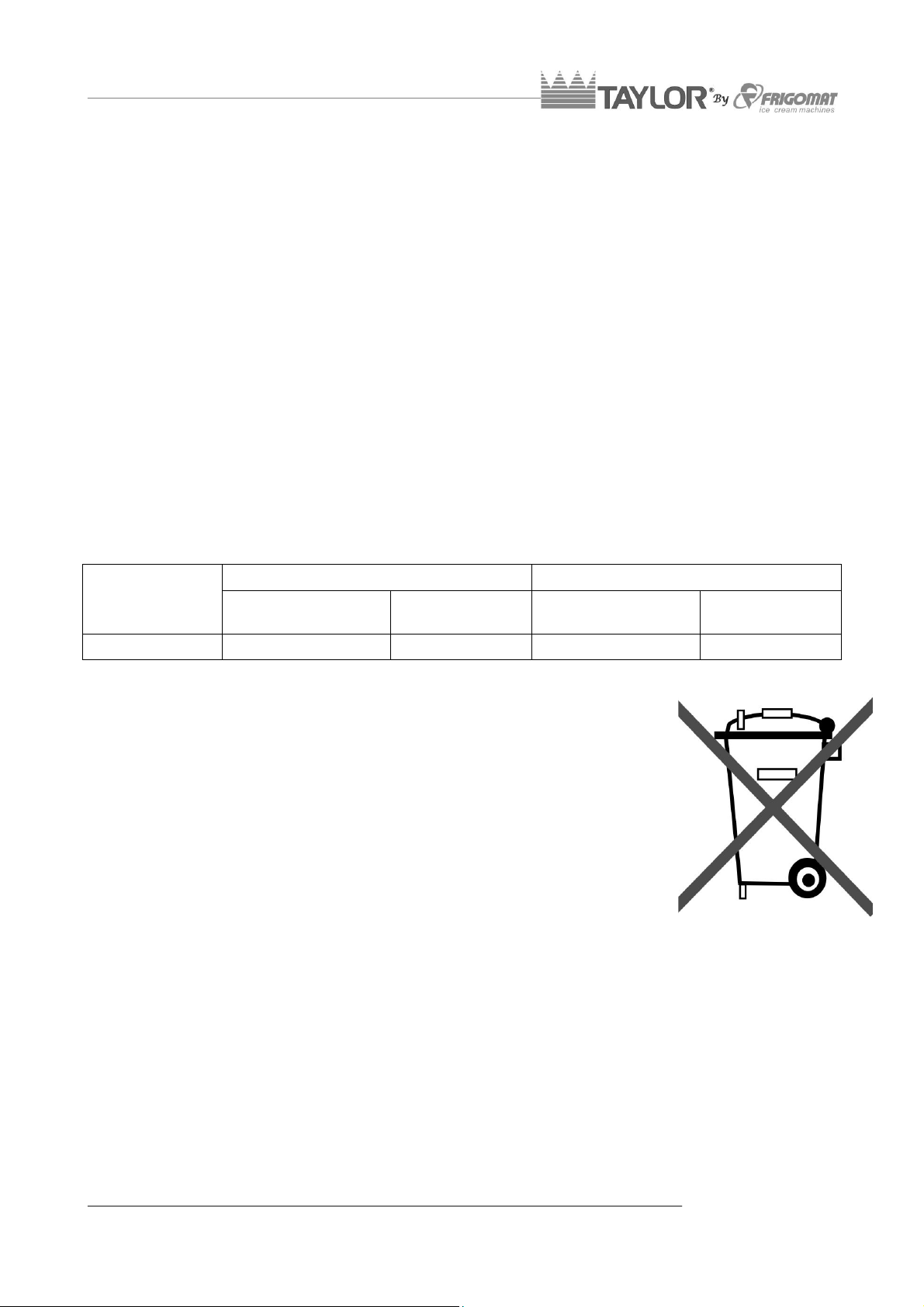
1.3 INDICATIONS FOR DECOMMISSIONING
The machine contains electrical and/or electronic materials and can
contain fluids and/or oil. If it must be decommissioned or disposed of,
comply with the Standards in force in the Country where it is used.
Even packaging materials (crates or boxes) must be divided by type
and disposed of in compliance with Standards in force in the Country
where it is used when the machine is decommissioned.
MEASUREMENTS
(CM)
WEIGHT N-G
(KG)
MEASUREMENTS
(CM)
WEIGHT N-G
60.5X50.5X53 35-42 - -
(KG)
ENGLISH - 4
Page 6
2. MARKING AND GRAPHIC SIGNS
The machine is provided with an identification plate and several pictograms. They must be
known along with the manual to guarantee safe use.
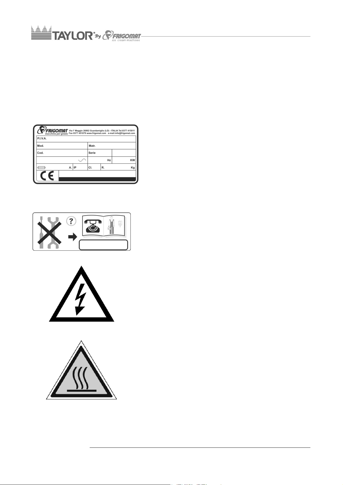
Machine data plate
The adhesive plate applied on the rear enables to
identify the model. It includes the following indications:
Name and address of the manufacturer; machine
model and version; serial number; nominal electrical
features; type and weight of gas used; year of
manufacture.
Attention!
Maintenance reserved for qualified personnel. This
plate applied on the rear panel prohibits extraordinary
maintenance and/or repairs to anyone but authorised
personnel, whose address is indicated in the space
provided.
Attention!
High voltage inside; electrocution hazard.
This plate is applied on the cover of the electrical box
and warns the operator that it must not be removed
for any reason whatsoever, thus avoiding the danger
of electrocution which could be fatal. In this case also,
maintenance of internal components is reserved for
qualified personnel.
Attention!
Burns hazard.
This plate is applied on the top of the machine and
warns the operator that the cover must be opened
with great care since he could be assailed by steam.
5 - ENGLISH
Page 7
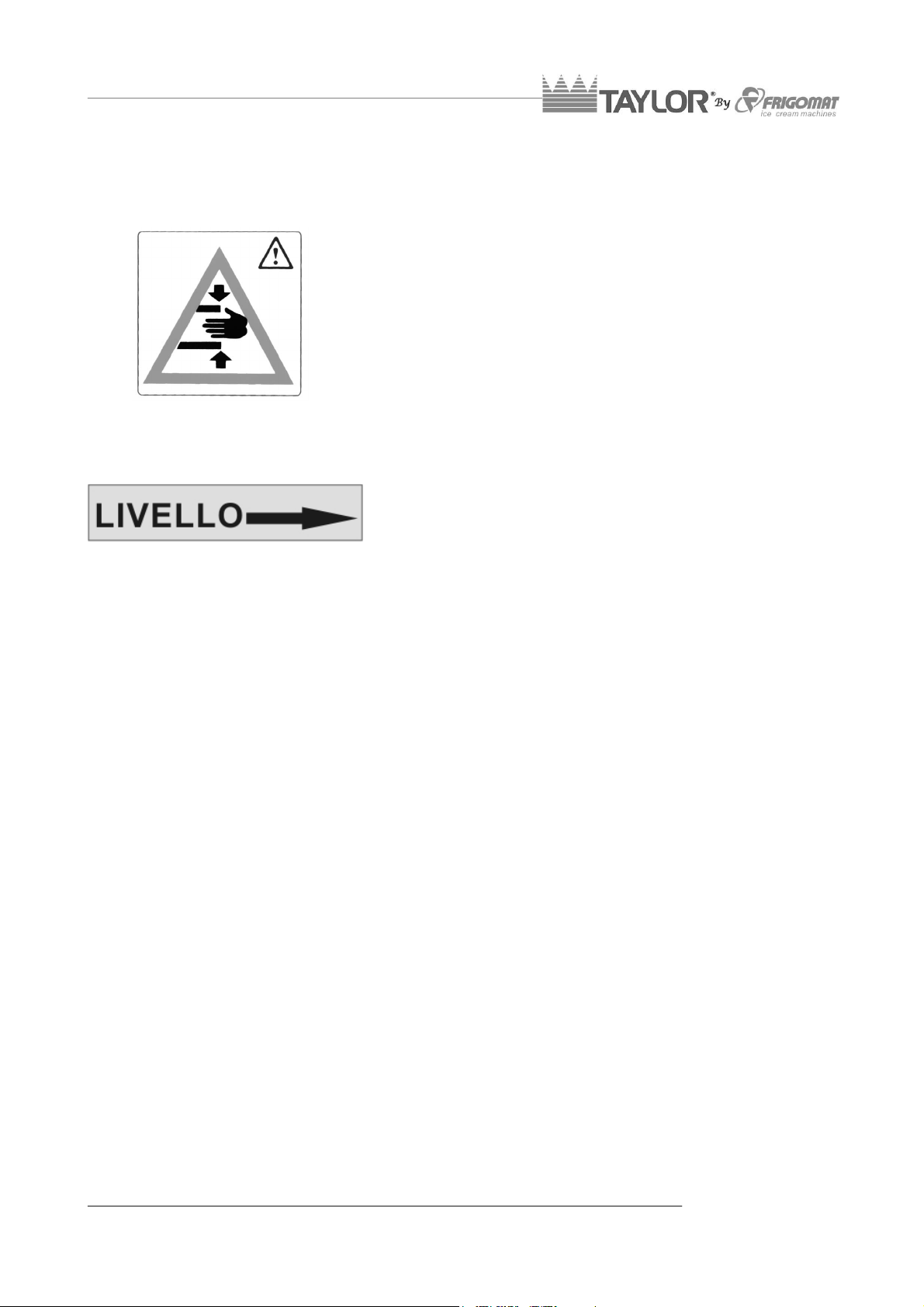
Attention!
Crushing hazard.
This plate is applied on the top panel at the right of the
vessel cover. It indicates that one must pay attention,
both during cleaning and charging, since it can fall
and injure the operator if hit.
All CHEF LCD cream cookers are equipped with an
advanced limb-shearing-prevention safety system
capable of stopping moving parts if the lid is opened.
Nonetheless, all cleaning and maintenance must be
performed with the machine at "STOP" and the
master switch disconnected.
Indication
Level of glycol.
The following label is attached on the tank wall of the
exchange fluid inside the machine and indicates the
optimal level of glycol.
ENGLISH - 6
Page 8

3. GENERAL SAFETY STANDARDS
Strictly comply with the general Safety and Accident-prevention Standards listed hereafter:
- Use of the machine is reserved for personnel in good health, responsible and
appropriately trained regarding allowed use and risks present.
- Use of the machine is reserved for operators who have read, understood and taken
in all that is included in this manual.
- It is forbidden to remove or tamper with the safety systems installed on the
machine.
- While the appliance is operating, it is mandatory to check that dangerous situations
for persons do not occur. Should these conditions transpire, stop the appliance
immediately.
- When you have finished working with the machine, it is mandatory to cut power by
acting on the master switch.
- When unusual noise or anomalous functioning is perceived, it is mandatory to
immediately stop operations in progress and to search for the cause of these
irregularities. If in doubt, avoid improper operations by contacting the
manufacturer's after-sales service.
- Any tampering or modification of the machine automatically entails the immediate
termination of the warranty and relieves the manufacturer of all and any liability for
direct or indirect damage caused.
- It is mandatory to check that the place where the machine is installed is ventilated
and correctly illuminated. The surface where the appliance is installed must be
solid, flat and levelled.
- During loading, unloading and handling operations, it is mandatory to use
equipment with a capacity adequate for the mass (weight) of the machine, using
hoisting devices and accessories with features and state of use suitable for the
purpose.
- Use only TAYLOR original spare parts when performing maintenance. The
manufacturer will not be held liable for damage caused by use of non-original spare
parts. Use of non-original spare parts entails automatic termination of the warranty.
- It is mandatory to position the machine far away from equipment which emits
electromagnetic radiation which could cause the circuit boards to malfunction.
- If fire-prevention equipment is necessary use types which are compatible with the
presence of voltage on board.
- It is forbidden to wear long and loose apparel, ties, jewellery, scarves or similar
clothing which could get caught in the moving parts of the machine.
- Hair must be tied back and shirt-sleeves tight.
7 - ENGLISH
Page 9
4. INSTALLATION
4.1 USE
Appliance suitable for the thermal processing bakery products and mixtures for ice cream,
according to use allowed by Law.
4.2 WORKING LIMITS
Do not use the machine with inconstant power supplies or +/- 10% beyond the value
indicated on the plate or with the power cable damaged;
Do not use the machine in explosive atmospheres;
Do not wash the machine with high-pressure water jets or with harmful substances;
Do not expose the machine to excessive heat or humidity;
Do not use unbalanced mixtures and/or amounts which do not comply with the
specifications carried on the packs.
Use not expressly indicated in this manual is to be considered improper and therefore
must be strictly avoided.
The manufacturer will not be held liable for direct or indirect harm to persons or animals or
damage to objects caused by improper use of the machine.
4.3 NOISE
SOUND EMISSION LEVEL EXPRESSED IN DECIBELS (measurement method A)
As foreseen by Machinery Directive 89/392 EN 23741 Standard
(A-weighted equivalent continuous sound pressure level)
MODEL LEVEL (A) MODEL LEVEL (A)
CH02
< = 68 dB (A)
4.4 SUPPLIED WITH MACHINE
-
- Spatula
- Brush
- Gasket extractor
- O-ring kit
- Lubricant
- Use and maintenance manual
- Declaration of conformity
- Warranty certificate
ENGLISH - 8
Page 10

4.5 ACTIVATION (INTENDED FOR QUALIFIED PERSONNEL)
TAYLOR declines all and any liability for damage caused by failure to comply with the
following indications. This lack of compliance causes the warranty to terminate.
Connection of the machine to the water mains must be performed in compliance with
national regulations of the Country where the machine is installed.
To commission the machine, bring it to the place of use, checking what is requested for its
installation:
• Make sure the appliance is positioned on a solid, stable, flat and levelled surface.
• If required, adjust the rear feet.
• Leave at least 10 cm between the machine and the walls or other obstacles.
• Check the exact correspondence between the voltage and power of the mains
compared to the values carried on the data plate applied on the rear panel;
• Connect the machine to the electrical power supply system. Install an omnipolar master
switch upstream the appliance with minimum contact opening of 3 mm of adequate
power, with a fuse and circuit breaker protective system. Use an approved interlocking
plug to allow only the open circuit to connect and disconnect.
• The cable must be well laid, without being rolled-up or overlapped. It must not be
exposed to blows or tampering. It must not be in the vicinity of liquids or water and heat
sources. It must not be damaged in any way. If so, before connecting the machine to
the mains, have it replaced by qualified personnel with another section and type 3G1.5
H05VV-F
• For safety purposes, make sure the earthing system to which the machine plug is
connected is compliant with standards and perfectly efficient.
• If needed, carry out an equipotential bonding, using the screw
placed on the rear of the machine below the frame and
marked with the symbol shown to the left.
• Operating temperature should be between 15° and 35°C.
• Humidity should be between 30 and 60%.
9 - ENGLISH
Page 11

5. SAFETY DEVICES
Motor overheating safety device: Implemented by means of self-resetting thermal
protectors (clixon) to protect the operation machine motors from overloads. Once the
normal work temperature is restored, reset occurs automatically.
Heat elements safety device: implemented by means of safety thermostat; it protects the
heat element from overheating, by signalling the relative alarm message on the display,
emitting an intermittent acoustic signal and allowing restore directly from the push button
control panel.
Protection against short circuit of auxiliary utilities: Implemented by fuses which
intervene on the logic unit or auxiliary power supply in the event of short-circuits.
SELV safety circuit: the push button control panel is powered at low voltage by means of
an approved dual-insulation safety transformer, protected against short circuits by fuses.
ENGLISH - 10
Page 12
6. OPERATION
6.1 MACHINE
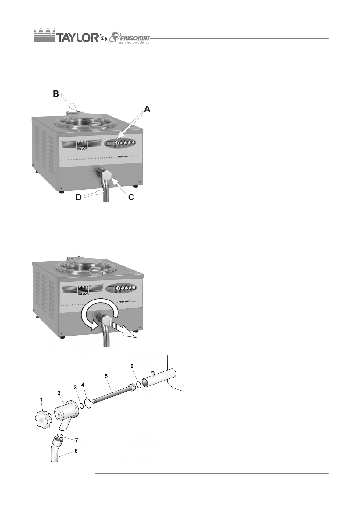
REMOVING THE DISPENSER TAP
A. Push button control panel
Enables to select the work programs.
B. Tank lid
Closes the tank during the processing phases. It can
be easily removed for cleaning.
C. Tap knob
Allows to adjust the extracting flow of the product from
the tank.
D. Dispenser tap
Used when extracting the product and emptying water
during the tank cleaning procedure.
• Release the dispenser tap by turning it
anticlockwise of 90° and then pull it as
indicated in the figure
• Remove the drain pipe pos 8 and remove and
grease the OR gasket pos. 7, using the
provided tool 7
• Loosen the hand wheel pos. 1 and remove the
piston pos 5, and then verify and lubricate the
gaskets pos. 3-4-6
• Once the unit has been re-assembled, block it
again.
11 - ENGLISH
Page 13
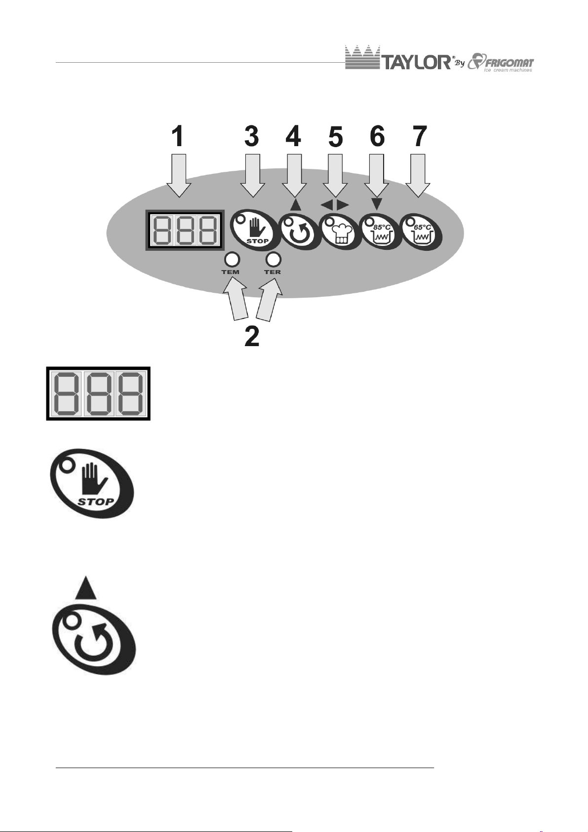
6.2 CONTROL PANEL
3. DISPLAY
Displays the information relative to work programs and allowed
adjustments.
4. STOP
In whatever operating phase the machine is in, pressing the STOP
key stops the machine and cancels the function in progress.
3. MIXING/UP (▲)
This button has 2 functions:
1. With the machine at STOP, by pressing the STIRRING key, the
2. With the machine in programming, by pressing the UP (▲) key it is
beater motor starts up and the LED turns on.
With the machine in SEMI-AUTOMATIC, AUTOMATIC 85°, and
AUTOMATIC 65° mode, by pressing the STIRRING key, the
ongoing operation interrupts, the machine changes to mixing only
and the LED turns on.
possible to increase the value of the selected parameter.
ENGLISH - 12
Page 14

4. SEMI-AUTOMATIC/CONFIRM (◄►)
This button has 4 functions:
1. Whatever the function in progress, the pressing the SEMI-AUTOMATIC
key, access is gained to the programming of the semi-automatic thermal
processing cycle, were it possible to program the maximum temperature
of the product in tank and time for which said temperature will be kept
constant.
2. With the machine in programming, by pressing the CONFIRM (◄►) key
it is possible to confirm the value of the selected parameter.
3. With the machine in SEMI-AUTOMATIC mode, by keeping the SEMIAUTOMATIC key pressed for at least 3”, the instantaneous temperature
of the bain-marie fluid is temporarily shown on display.
4. With the machine in SEMI-AUTOMATIC mode, by keeping the SEMIAUTOMATIC key pressed for at least 10”, access is gained to the
control mode of the bain-marie fluid programming (only for qualified
personnel).
5. AUTOMATIC 85°/ DOWN (▼)
This button has 4 functions:
1. Whatever the function in progress is, by pressing the AUTOMATIC 85°
key, the key LED switches on and starts the automatic heating cycle at
85°C.
2. During programming, by pressing the DOWN (▼) key it is possible to
reduce the value of the selected parameter.
3. With the machine in AUTOMATIC 85° mode, by keeping the
AUTOMATIC 85° key pressed for at least 3”, the instantaneous
temperature of the bain-marie fluid is temporarily shown on display.
4. With the machine in AUTOMATIC 85° mode, by keeping the
AUTOMATIC 85° key pressed for at least 10”, access is gained to the
control mode of the bain-marie fluid programming (only for qualified
personnel).
6. AUTOMATIC 65°
This button has 4 functions:
1. Whatever the function in progress is, by pressing the AUTOMATIC 65°
key, the key LED switches on and the automatic heating cycle at 65
starts with subsequent maintenance for 30'.
2. With the machine in AUTOMATIC 65° mode, by keeping the
AUTOMATIC 65° key pressed for at least 3”, the instantaneous
temperature of the bain-marie fluid is temporarily shown on display.
3. With the machine in AUTOMATIC 65° mode, by keeping the
AUTOMATIC 65° key pressed for at least 10”, access is gained to the
control mode of the bain-marie fluid programming (only for qualified
personnel).
7.LED TER - TEM
The LED switches on to signal any system anomalies.
13 - ENGLISH
Page 15

6.3 THERMAL PROCESSING OF MIXTURES
After having installed the machine in compliance with the instructions of chapter 3 and
having accurately washed and sanitised it, according to the instructions contained in
chapter 7, proceed as follows to start thermal processing:
- Make sure the master switch is closed and that
the machine is powered correctly.
- Make sure the dispenser tap is closed and that the
tank beater is assembled correctly.
- Lift the cover and pour the ingredients in the tank,
strictly observing the minimum and maximum
amounts admitted per cycle and carried on the
following table:
MODEL
CH02
Failure to comply with the minimum and maximum
load values can entail machine malfunctioning and
even breakage.
- Lower the lid and select the wanted work cycle,
referring to the instructions in the successive
paragraphs.
MIN
(LITRES)
3 8
MAX
(LITRES)
ENGLISH - 14
Page 16

6.3.1 AUTOMATIC CYCLE 85°C
Fig.1
Fig.2
Fig.3
Fig.4
- Press the AUTOMATIC 85° key to start the
automatic heating cycle at 85°C. The key LED such
as on and the instantaneous temperature of the
product in tank during the entire processing cycle is
shown on display (fig.1-2).
- When a few minutes have elapsed and temperature
of 85°C is reached, the display flashes and the
buzzer sounds intermittently to inform the operator
that the boiling mixture can be removed (fig.3). If
this is not possible right away, the beater will keep
on mixing and the electrical heat element will hold
the mixture at the correct temperature, thus starting
the PRESERVATION phase without limits of time.
- During the preservation phase, the temperature of
the product in tank flashes on the display.
- It is possible to go to the product extraction phase
at any time (fig.3).
At any moment, it is possible to verify the
instantaneous temperature value of the bain-marie
fluid by keeping the AUTOMATIC 85° key pressed
for at least 3" (fig.4). This value will be displayed for
about 10".
15 - ENGLISH
Page 17

6.3.2 SEMI-AUTOMATIC CYCLE
Fig.1
Fig.2
Fig.3
Fig.4
Fig.5
- Press the SEMI-AUTOMATIC key to select
the semi-automatic thermal treatment cycle
with temperature and stand-by time control
(Fig. 1).
- The LEDs of the UP (▲), Confirm (◄►) and
DOWN (▼) keys start flashing and the
numbers relative to the set of temperature to
be configured, between 30 and 90, appear
on the display: press the “UP (▲)” and
“DOWN (▼)” keys to increase or decrease
this value (Fig. 2). Once the wanted value is
reached, press the CONFIRM (◄►) key to
save the programming made (Fig. 3).
- After programming of the temperature set to
be reached, select the time during which this
temperature is kept constant.
- The LEDs of the UP (▲), Confirm (◄►) and
DOWN (▼) keys start flashing and the
numbers relative to the set of time to be
configured, between 0' and 10' hours, appear
on the display: press the “UP (▲)” and
“DOWN (▼)” keys to increase or decrease
this value (Fig. 4).
- Once the wanted value is reached, press the
CONFIRM (◄►) key to save the
programming made and start the processing
cycle (Fig. 5).
By selecting heating temperatures between
65° and 85°C, the machine automatically
calculates the stand-by time required to
guarantee absolute product hygiene.
This time value can be modified at any time,
but it is strongly advised against as products
with excessively high bacterial loads may be
obtained.
- Once the programmed temperature is
reached and any standby time has passed,
the display flashes and the buzzer sounds
intermittently, to inform the operator that the
mixture can be extracted (fig.6). If this is not
ENGLISH - 16
Page 18

Fig.6
Fig.7
possible right away, the beater will keep on
mixing and the electrical heat element will
hold the mixture at the correct temperature,
thus starting the PRESERVATION phase
without limits of time.
- During the preservation phase, in addition to
any programs downtime time, the
temperature of the product in tank flashes on
the display (fig.6).
- It is possible to go to the product extraction
phase at any time.
At any moment, the instantaneous
temperature value of the bain-marie fluid can
be verified, by keeping the SEMIAUTOMATIC (fig.7) key pressed for at least
3". This value will be displayed for about 10".
17 - ENGLISH
Page 19

6.3.3 AUTOMATIC CYCLE 65°
Fig.1
Fig.2
Fig.3
Fig.4
- Press the AUTOMATIC 65° key to start the
automatic heating cycle at 65° and subsequent
maintenance for 30'. The key LED such as on and
the instantaneous temperature of the product in
tank during the entire processing cycle is shown on
display (fig.1-2).
- Once the temperature of 65° is reached and 30'
standby time has passed, the display flashes and
the buzzer sounds intermittently, to inform the
operator that the mixture can be extracted (fig.3). If
this is not possible right away, the beater will keep
on mixing and the electrical heat element will hold
the mixture at the correct temperature, thus starting
the PRESERVATION phase without limits of time.
- During the preservation phase, the temperature of
the product in tank flashes on the display.
- It is possible to go to the product extraction phase
at any time (fig.3).
At any moment, it is possible to verify the
instantaneous temperature value of the bain-marie
fluid by keeping the AUTOMATIC 65° key pressed
for at least 3" (fig.4). This value will be displayed for
about 10".
ENGLISH - 18
Page 20

6.5 EXTRACTION OF BOILING MIXTURES
- Ensure the amount of product to be
transferred is compatible with the useful
capacity of the container of destination.
- Make sure the heater tap is in vertical position
to allow the product to flow directly into the
container you wish to use.
- Regardless of the function in progress, press
the STIRRING key on the control panel of the
heater (fig.1).
To quickly and completely remove the
product from inside the vessel, the beater
must always be operating.
- To begin the transfer, pull the knob slowly
and carefully.
Pay the utmost attention during transfer of
boiling mixtures; handle the tap piston with
extreme care, use suitable containers and
take all possible precautions to reduce the
risk of injuries, even serious, due to contact
with boiling product.
F
- When the entire product has been transferred
inside the container and the heater vessel is
empty, push the piston to the closed position.
- Press “STOP” on the heater control panel
(fig.3).
19 - ENGLISH
Page 21

7. MAINTENANCE
7.1 ROUTINE MAINTENANCE (INTENDED FOR USER)
The fats present in the ice cream mixtures are ideal fields for the proliferation of bacterial
loads and mould. To eliminate this serious problem, all the parts which come into contact
with the product must be thoroughly washed and sanitized by careful procedures and
using suitable sanitizing products. The stainless and plastic materials used on our
machines, in fact, comply with the strictest international provisions and their special shape
facilitates their washing. However this is not enough to prevent the formation of mould and
bacteria caused by insufficient or incorrect cleaning.
TAYLOR recommends thoroughly washing and sanitizing the parts in direct contact with
the product after each work shift and in compliance with hygienic standards in force in the
Country where the machine is installed.
To correctly clean your machine, refer to the following operations:
PREWASHING
• Pour the maximum admitted load of warm
(approximately 50°C) drinking water into the tank.
• Press the MIXING key to start the beater motor. Let it
run for about 3’. Open the dispenser tap and drain all
the wash water. Repeat the procedure until the water
coming out is clear and clean.
• Pour the maximum load admitted of
cleanser/sanitizer into the tank.
• Press the STIRRING button to start the beater motor.
Let it run for about 15’. Open the dispenser tap and
drain the sanitizer.
•
We suggest using the following sanitising
solution:
Ecolab P3 Topax-san
(4% dilution = 200 ml).
ENGLISH - 20
Page 22

Pour the maximum admitted load of cold drinking
water into the tub to rinse the surfaces which were
just treated with the sanitizer.
• Drain the rinse water and turn the machine off.
• When pre-washing is over, all the removable parts in
contact with the product must be disassembled and
sanitized in a separate tub.
SANITIZING REMOVABLE PARTS
PREPARATION OF WASHING TUB
• Wash your hands well and/or wear disposable
gloves.
• Fill a clean tub with a sufficient amount of drinking
water at approximately 50°C and the sanitizer.
REMOVING AND CLEANING COVER
• Pull the hinge pin off and remove the cover, holding it with both hands.
Emerge the previously disassembled components into the tub with the sanitizer and
brush the surfaces with care. Pay special attention to the surfaces in direct contact with
the product.
We suggest using the following sanitising
solution:
Ecolab P3 Topax-san
(4% dilution = 200 ml every 5 litres of water).
• Prepare the supplied brush and the OR disassembly
device and immerse them in the solution.
21 - ENGLISH
Page 23

REMOVING AND CLEANING BEATER
• Pull the beater upwards to pull it out of the tub.
• Emerge the previously disassembled component into
the tub with the sanitizer and brush the surfaces with
care. Pay special attention to the inner duct of the
beater shaft.
REMOVING AND CLEANING THE TAP
• Rotate the tap block anticlockwise and of 90° until
releasing it.
• Pull the block tap until removing it from the machine.
• Remove the drain pipe pos 8 and remove the OR
gasket pos. 7, using the provided tool 7
• Loosen the hand wheel pos. 1 and remove the piston
pos 5.
• Emerge the previously disassembled components
into the tub with the sanitizer and brush the surfaces
with care. Pay special attention to the inner duct of
the tap, to the holes and seats of the OR.
All the disassembled parts must remain soaking in the Ecolab P3 Topax-san sanitizer
(4% dilution) for at least 15’ before they are rinsed with plenty of cold drinking water.
SANITIZING FIXED PARTS
While the removable parts soak in the sanitizer
inside the tub, proceed sanitizing the fixed parts of
the machine:
SANITIZING THE TUB
• Immerse a disposable paper cloth in the sanitising
liquid.
• Pass the cloth over all the surfaces of the tub and
fixed transmission shaft.
• Pass the cloth over the outer edge of the tub until
reaching the surfaces of the cover and front panel.
ENGLISH - 22
Page 24

• Use the brush previously emerged in the sanitizer to thoroughly clean the drain duct
which connects the tank to the tap.
• Never use any type of solvents and/or thinners to preserve the plastic parts and
gaskets during washing.
• Chemical sanitizing products must be used in compliance with standards in force and
with the utmost caution.
• During sanitizing operations, do not touch parts with tissues, sponges, rags or any
other non-sterile material.
RINSING AND DRYING
• Wash your hands well and/or wear disposable latex
gloves.
• Remove from the sanitising tank all the components
which were previously disassembled, brushed and
immersed.
• Rinse them with plenty of cold drinking water, making
sure to remove all possible leftover sanitising solution.
• Place the rinsed components on a clean table and let
them dry in the air.
DO NOT use rags, sponges or anything else to dry the
components. Make sure no dust or other impurities
come into contact with the sanitized surfaces while
they are drying.
• Also carefully rinse the fixed parts of the machine
which were treated with the sanitizing solution
(cylinder, drive shaft, etc.)
• When all the components are dry, put them back onto
the machine, making sure the gaskets are in good
conditions.
23 - ENGLISH
Page 25

7.3 EXTRAORDINARY MAINTENANCE (INTENDED FOR QUALIFIED PERSONNEL)
g.2
g
These operations are reserved exclusively for authorised qualified personnel. TAYLOR
S.r.l. will not be held liable for damage to objects or harm to persons which occur due to
failure to comply with the above.
HEATER MEB² BOARD PROGRAMMING
Refer to the following instructions to program the circuit board:
Fig.1
1. Ensure the lid is assembled in machine and in
closing position.
2. Power the machine.
3. With the machine at STOP, press the “STOP” and
“MIXING” keys simultaneously and release them
only after the password identification screen
appears (fig.1).
Fi
4. Press the “MIXING(▲)”, “AUTOMATIC 85° (▼)”
and “SEMI-AUTOMATIC (◄►)” keys to enter the
password and then confirm it (fig.2). If you do not
know the password, contact the TAYLOR
assistance service.
5. When the password has been accepted, the screen
accesses the list of programming steps directly. The
Fi
.3
first programming step P01 is selected
automatically
6. If you do not wish to change the value of the
selected step, press “MIXING (▲)” to directly
access the following step (Fig. 3).
7. If, instead, you wish to change the selected step,
press ““SEMI-AUTOMATIC (◄►)” to access the
Fig.4
parameters relative to the same step, and
subsequently press “MIXING (▲)” or “AUTOMATIC
85° (▼)” to increase or decrease the value.
Subsequently, press the “SEMI-AUTOMATIC
(◄►)” key to confirm the data (fig.4).
8. To exit programming and save the changes press
Fig.5
the "STOP" key (fig.5).
ENGLISH - 24
Page 26

“MEB²” BOARD PROGRAMMING TABLE (**)
P DESCRIPTION MIN MAX CH02 STEP
P1 Model Selection 1 2 2
P2 Tank probe correction (TEV) -10° +10° * 0,5°C
P3
P4
P5
P6
P7
P8
P9 Lim. control hysteresis TEF 1° 10° 1° 1°C
P10 Temperature indication on display 0 1 1
compensation when TEV>40°C
TEF Control Lim. in AUTOMATIC
Probe correction
fluid (TEF)
Tank overtemperature
TEF Control Lim. in SEMI-
AUTOMATIC
85° and 65°
Not active
Not active
-10° +10° * 0,5°C
-10° +10° * 0,5°C
30° 130° 98° 1°C
30° 130° 98° 1°C
1= TWIN
2= CH02
0=°F
1=°C
9.
(*) These parameters vary for each unit and variant.
(**) The parameters may vary depending on the software version or customisation. It is
always possible to refer to the test inspection board supplied with the machine.
25 - ENGLISH
Page 27

8. TROUBLESHOOTING INSTRUCTIONS
8.1 MANAGEMENT OF HEATER ALARMS
MESSAGE DESCRIPTION REMEDIES
Wait a few minutes and then
press STOP to restore machine
operation.
If the alarm continues, contact
the technician.
TER
A circuit breaker or the transformer fuse
has intervened.
The buzzer emits an intermittent acoustic
signal.
DIS
TEv Int
TEv cor
TEf Int
TEf cor
Communication between the board and
the display interrupted.
The tank probe is interrupted.
The buzzer emits an intermittent acoustic
signal.
The tank probe is in short-circuit.
The buzzer emits an intermittent acoustic
signal.
The fluid probe is interrupted.
The buzzer emits an intermittent acoustic
signal.
The fluid probe is in short-circuit.
The buzzer emits an intermittent acoustic
signal.
Contact the technician.
Contact the technician to check
and replace the faulty probe.
Contact the technician to check
and replace the faulty probe.
Contact the technician to check
and replace the faulty probe.
Contact the technician to check
and replace the faulty probe.
ENGLISH - 26
Page 28

8.2 HEATER TROUBLESHOOTING
PROBLEM PROBABLE CAUSES REMEDIES
Master switch open. Close the switch.
The machine does not start
(STOP button off).
Electrical anomaly. Contact the technician.
Fuses blown. Contact the technician.
After the extraction there is
still too much product in the
vessel
The machine works regularly
but the heating times are
long.
During functioning the
machine becomes noisy and
the beater stops.
The machine becomes noisy
during operation.
The machine does not heat
within normal time and a loss
of blue fluid is detected
under the machine.
Adjust the rear feet so that the
Insufficient rear feet adjustment.
Product insufficient.
Open lid.
Faulty resistance or fluid pump. Contact the technician.
The belt slips.
Transmission shaft without
lubrication.
Loss of glycol from the system. Contact the technician.
product contained in the vessel
comes out.
Work with at least 1/2 the
maximum amount of product
allowed.
Make sure that the lid is
assembled and closed properly.
Contact the technician to check
the belts tension and possibly
replace it.
Remove the mixer and pull the
transmission shaft upwards.
Verify and lubricate with food
grease.
27 - ENGLISH
Page 29

9 APPENDICI / APPENDICES / ANNEXES / ANHANG / APENDICES
9.1 Dati tecnici / Machine specifications / Caractéristiques techniques / Technische
Daten / Datos Tecnicos
Modello
Model
Modell
Modale
Modelo
Alimentazione
Current
Stromart
Tension
Tensiòn
Potenza
Power
Nennleistung
Puissance
Potencia
Altezza
Height
Höle
Hauteur
Altura
Larghezz
a
Width
Breite
Largeur
Anchura
Profondità
Dept
Tiefe
Profondeur
Profundidad
Peso
Weight
Gewicht
Poids
Peso
CH02
(kw) (cm) (cm) (cm) (kg)
220/50-60/1 2,2 33 43 49+7 35
1 - APPENDICI
Page 30
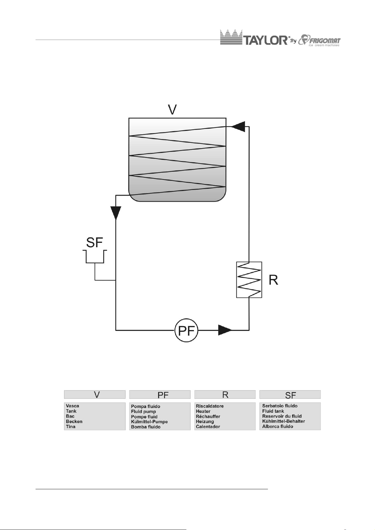
9.2 Schema circuito frigorifero / Refrigerant circuit diagram
APPENDICI - 2
Page 31

9.3 IMPIANTO ELETTRICO / ELECTRIC SYSTEM / GROUPE ELECTRIQUE /
ELEKTRISCHE ANLAGE / INSTALACION ELECTRICA
3 - APPENDICI
Page 32

9.4 RICAMBI / SPARE PARTS / PIECES DETACHEES / ERSATZTEILE / REPUESTOS
Per la richiesta delle parti di ricambio, si raccomanda di indicare sempre il numero di codice
relativo e la denominazione riportata sulla legenda di ciascuna tavola. Si raccomanda inoltre di
comunicare sempre il modello ed il numero di matricola della macchina, nonché le caratteristiche
della stessa (voltaggio, frequenza e fasi), facilitando in tal modo l’identificazione del particolare.
Per ordinare la componentistica di ricambio del compressore indicare sempre anche il modello
specificato sulla targhetta del motore. In caso di sostituzione di pezzi, richiedere solo ricambi
ORIGINALI TAYLOR ad un concessionario o ad un Rivenditore Autorizzato. TAYLOR declina ogni
responsabilità per danni a persone e/o cose derivanti dall’utilizzo di ricambi non originali.
For spare parts ordering, always mention the corresponding code number and the name reported
on each table caption. It is also recommended to always mention the machine model and the serial
number as well as the technical data (voltage, frequency and phases), to make the identification of
the component easier. To order spare parts for the compressor, always mention the model
specified on the motor nameplate. In case it is necessary to replace a component, always ask a
distributor or an authorized retailer for ORIGINAL spare parts. TAYLOR declines any liability for
damages to people and/or things due to employment of non-original spare parts.
En cas de demande de pièces détachées, l’on recommande vivement d’indiquer le numéro de
code correspondant et la description figurant sur la légende de chaque tableau. L’on recommande
aussi de communiquer le modèle et le numéro d’immatriculation de la machine, ainsi que ses
caractéristiques (voltage, fréquence et phases), afin de faciliter l’identification de la pièce. Pour
commander les composants de rechange du compresseur, il faut également indiquer le modèle qui
est spécifié sur la plaque d’identification du moteur. En cas de remplacement de pièces, demander
uniquement des pièces détachées ORIGINALES TAYLOR en vous adressant à un
concessionnaire ou à un Revendeur Autorisé. TAYLOR décline toute responsabilité en cas de
dommages aux personnes ou aux choses qui dériveraient de l’utilisation de pièces détachées non
originales.
Für die Anfrage von Ersatzteilen raten wir Ihnen, immer die Kodenummer und die entsprechende
Benennung einer jeden Tafel mitzuteilen. Wir raten weiterhin, immer das Modell und die
Seriennummer der Maschine mitzuteilen als auch die Maschineneigenschaften (Voltleistung,
Frequenz und Phasen), um die Erkennung von Besonderheiten zu vereinfachen. Um Ersatzteile
des Kompressors zu bestellen, muß man auch das direkte Modell angeben, welches auf dem
Motorschild verzeichnet ist. Im Austauschfall von Teilen nur Originalteilen der Firma Firgomat beim
Konzessionär oder autorisiertem Wiederverkäufer anfragen. Die Firma TAYLOR ist von jeglichem
Schadensersatz an Personen u/o Gegenständen entbunden, die auf den Einsatz von nicht
originalen Ersatzteilen zurückzuführen sind.
Para la petición de las partes de recambio, se recomienda indicar siempre el número de código
relativo y la denominación indicada en la leyenda de cada tabla. Además, se recomienda
comunicar siempre el modelo y el número de matrícula de la máquina, así como las características
de la misma (voltaje, frecuencia y fases), facilitando de esta manera la identificación de la parte.
Para pedir los componentes de recambio del compresor indicar siempre también el modelo
especificado en al placa del motor. En caso de sustitución de piezas, pedir sólo recambios
ORIGINALES TAYLOR a un concesionario o a un Revendedor Autorizado. TAYLOR declina
cualquier responsabilidad por daños a personas y/o cosas derivados del uso de recambios no
originales.
APPENDICI - 4
Page 33

CH02 s05 Tav.1
5 - APPENDICI
Page 34

CH02 s05 Tav.1
P. COD. DESCRIZIONE DESCRIPTION DESCRIPTION BESCHREIBUNG DESCRIPTION
1
2
-
3
4
5
6
7
8
9
10
11
12
13
14
A06.185
E15.40826
E13.38654
E15.40831
M02.38287
P14.37043
F03.325
A02.38240
P06.077
F01.160
C03.189
L19.37042
B15.037
B15.038
B09.215
Gruppo isolamento Insulation unit Groupe isolant Isolationsgruppe Grupo aislamiento
Scheda pulsantiera
Cavo scheda
pulsantiera
Scheda comando Control card Carte de commande Bedienungskarte Tarjeta de mando
Etichetta anteriore Front label Etiquette antérieure Frontkleber Etiqueta anterior
Piedino Foot Pied Fuss Pie
Protezione fondo Bottom guard Protection du fond Bodenschutz Protección Fondo
Carenatura anteriore Front panel Panneau Frontal Vordere Blechtafel Panel anterior
Piedino Foot Pied Fuss Pie
Telaio Frame Châssis Gestell Armazón
Pannello posteriore Back panel Panneau postérieur Hinteres Blech Panel posterior
Perno cerniera Hinge Pin Goujon pour fermoir Scharnierstift Perno para bisagra
Cerniera fissa Fixed hinge Fermoir fixe Festes Scharnier Bisagra fija
Cerniera mobile Moving hinge Fermoir mobile
Vite cerniera Hinge screw Vis pour fermoir Scharnierschraube Tornillo para bisagra
Pushbutton panel
card
Wiring pushbutton
panel card
Carte du tableau de
commande
Cable carte du
tableau de
Tastenkarte
Tastenkarte-Kabel
Bewegliches
Scharnier
Tarjeta caja
pulsadores
Cablo tarjeta caja
pulsadores
Bisagra móvil
15
P16.37041
Coperchio Cover Couvercle deckel Tapa
APPENDICI - 6
Page 35

CH02 s05 Tav.2
7 - APPENDICI
Page 36

CH02 s05 Tav.2
P. COD. DESCRIZIONE DESCRIPTION DESCRIPTION BESCHREIBUNG DESCRIPTION
1
2
A02.164
A06.199
Termostato di
sicurezza
Corpo riscaldatore Heater body Corp du réchauffeur Heizergehaeuse Cuerpo Calentador
Safety thermostat
Thermostat de
sécurité
Sicheruheits-
Thermostat
Termostato
3
4
5
6
7
8
9
10
11
12
13
14
15
16
D08.046
P10.128
A06.198
C06.072
P03.194
P26.37681
T10.090
B13.015
R07.022
P10.137
B01.394
D04.215
E05.38215
P10.105
Resistenza Resistance Résistance Wiederstand Resistencia
Guarnizione
OR 6225
Riscaldatore
completo
Serbatoio fluido Fluid Tank Réservoir de fluid Flussigkeitsbehaelter Depósito fluido
Tappo per sebatoio Fluid tank plug Bouchon du résérvoir
Indicatore liquido Liquid sight glass Témoin pour liquide
Tubo sfiato Drain pipe
Fascetta 16-27/9 Clamp 16-27/9 Bague 16-27/9 Klemme 16-27/9 Abrazadera 16-27/9
Portagomma Hose connector Terminal de douche Schlauchansnschluß Portagoma
OR 120 OR 120 OR 120 OR 120 OR 120
Motopompa Pump mtor Moteur pompe Motorpumpe Motor Bomba
Condensatore
avviamento
Sonda temperatura Temperature probe Sonde température Temperatursonde Sonda temperatura
OR 123 OR 123 OR 123 OR 123 OR 123
OR 6225 OR 6225 OR 6225 OR 6225
Heater assy Réchauffeur complet Heizer kompl. Calentador completo
Start condenser
Tuyau
d’échappement
Condensateru de
demarrage
Verschluss
Flussigkeitsbehaelter
Flüssigkeitskontrolla
mpe
Überlaufrohr Tubo de desfogue
Startkondensator Condensador
Tapón depósito fluido
Testigo líquido
17
T10.093
Tubo gomma (nero)
15X25,5
Rubber tube (black)
15X25,5
Tuyau de coutchouc
(noir) 15X25,5
Gummirohr (schwarz)
15X25,5
Tubo goma (nero)
15X25,5
APPENDICI - 8
Page 37

CH02 s05 Tav.3
9 - APPENDICI
Page 38

CH02 s05 Tav.3
P. COD. DESCRIZIONE DESCRIPTION DESCRIPTION BESCHREIBUNG DESCRIPTION
1
2
B06.401
P10.077
Canotto agitatore Beater holding tube
Guarnizione OR 119 OR 119 OR 119 OR 119 OR 119
Tuyau porte-
mélangeur
Ruehrwerksroerchen Barra porta Agitador
3
4
5
6
7
8
9
10
11
12
13
14
15
16
17
18
19
B10.265
B06.400
A11.38270
B06.402
V14.072
B14.036
L06.38173
L21.38174
V13.069
B10.264
P02.36780
B02.158
E01.37826
A04.37828
A05.045
A05.046
E06.37827
Boccola Bush Douille Buchse Anillo
Albero agitatore Beater shaft Arbre mélangeur Ruerwerkswelle Eje Agitador
Bronzina Bushing Douille en bronze Bronzenbuchse Casquillo
Centrante Pipe guide Centreur Zentralrohr Centrador
Seeger Seeger Seeger Seeger Seeger
Cuscinetto Bearing Galet Rolle Cojinete
Puleggia condotta
Completa di boccola
Distanziale Shim Rondelle Scheibe Distanciador
Dado EMB 14 Nut Ecrou Mutetr Tuerca
Fondello inferiore Bottom Fond Boden Fondo
Cinghia Belt Courroie Riemen Correa
Puleggia conduttrice Guide pulley Poulie de condite Geführte Rolle Polea conductora
Motore mescolatore Mixer motor Moteur mélangeur Rühmotor Motor mezclador
Supporto copriventola Fan cover support
Ventola Fan Ventilateur
Copriventola Fan cover
Condensatore marcia Running condenser Condensateur allure Betriebskondensator Condensador
Guided pulley Poulie conduite Geführte Rolle Polea conducta
Support Couverture
du ventilateur
Couverture du
ventilateur
Fluegelraddecke
-halter
Flügelrad
Fluegelraddeckel Cobertura ventilador
Soporte Cobertura
ventilador
Aventador
APPENDICI - 10
Page 39

CH02 s05 Tav.4
11 - APPENDICI
Page 40

CH02 s05 Tav.4
P. COD. DESCRIZIONE DESCRIPTION DESCRIPTION BESCHREIBUNG DESCRIPTION
1
2
3
4
5
6
7
8
P02.176
B12.174
P10.110
P10.045
B12.168
P10.077
P10.136
B12.170
Pomello fissaggio Handle Poignée Griff Pomo
Corpo rubinetto Cock body Corp du Robinet Abgabehangehaeuse Cuerpo Grifo
Guarnizione OR 112 OR 112 OR 112 OR 112 OR 112
Guarnizione OR 3100 OR 3100 OR 3100 OR 3100 OR 3100
Pistone Piston Piston Kolben Piston
Guarnizione OR 119 OR 119 OR 119 OR 119 OR 119
Guarnizione OR 3087 OR 3087 OR 3087 OR 3087 OR 3087
Tubo di scarico Drain Pipe Tube d’écoulement Abflussrohor Tubo de descargo
APPENDICI - 12
Page 41

NOTE / NOTES / NOTES / BEMERKUNG / NOTA
Page 42

Page 43

FRIGOMAT s.r.l., via 1° Maggio 26862 GUARDAMIGLIO (LO) – ITALIA
tel. 0377.415011 – Fax. 0377.451079
www.frigomat.com
info@frigomat.com
MARZO 2013
 Loading...