

Page 1

OPERATING INSTRUCTIONS
AND MAINTENANCE
Series-Série-Serie
C124 04
C125 03
Page 2

1 - ENGLISH
Page 3

ENGLISH - 2
IMPORTANT
We recommend to carefully and fully read the present manual before using your
TAYLOR machine.
In your own interest, pay particular attention to the following warnings:
The non-observance of this warning can jeopardize the user’s health and the
correct operation of the machine.
A careful observance of these warnings can lead to a top performance of the
machine.
The machine is covered by guarantee according to the conditions reported in the
“GUARANTEE CARD “ enclosed to the machine, which shall be duly filled up and sent
back to:
FRIGOMAT s.r.l., via 1° Maggio 26862 GUARDAMIGLIO (LODI) – ITALIA
In the following field, please write your machine serial number in capital letters
Serial number
Distributor’s stamp
Page 4

3 - ENGLISH
INDEX
1. TRANSPORT, HANDLING AND STORAGE………………………………… 4
1.1 Preliminary Inspection ………………………………………… 4
1.2 Machine unpacking ………………………………………… 4
1.3 Packing dimensions ………………………………………… 4
2. MARKING AND GRAPHICS ………………………………………… 5
3. INSTALLATION ………………………………………… 6
3.1 Field of use ………………………………………… 6
3.2 Limits of use ………………………………………… 6
3.3 Machine outfit ………………………………………… 6
3.4 Commissioning ………………………………………… 6
4. OPERATIONS ………………………………………… 7
4.1 Controls ………………………………………… 7
4.2 Ice cream and granita production………………………………….… 9
4.3 Coffee-granita production ………………………………………… 10
4.4 Conservation of ice cream ………………………………………… 11
5. MAINTENANCE ………………………………………... 12
5.1 Routine maintenance ………………………………………… 12
6. TROUBLE-SHOOTING ………………………………………… 14
7. APPENDIXES ………………………………………… A1
7.1 Technical data ………………………………………… A1
7.2 Refrigerant circuit diagram ………………………………………… A2
7.3 Wiring diagram ………………………………………… A3
7.4 Spare parts ………………………………………… A4
Congratulations on purchasing a machine TAYLOR.
The present manual, enclosed to the machine, is integrant and essential part of the
machine and shall be delivered to the final user. Before performing any kind of operation, it
is recommended to carefully study the reported instructions, as only a careful reading
allows you getting the highest performance from your machine. The following pages report
all information necessary to correctly install, commission, adjust and service your machine.
TAYLOR reserves the right to carry out all changes necessary to improve its product or
manual without prior notice and to insert them in the subsequent issues.
Page 5
ENGLISH - 4
1 TRANSPORT, HANDLING AND STORAGE.
MODEL
CASE
SIZES (CM)
WEIGHT N- L (KG)
C124
56,5 X 52,5X h. 48,5
45-63
C125
595 X 590 X h. 465
55-73
1.1 PRELIMINARY INSPECTION
The machine travels at the customer’s risk. In case packing is damaged, immediately
inform the carrier.
Immediately inform the carrier also in case of damage to the machine, even if you open
the packing a few days after the delivery.
It is always advisable to accept the goods SUBJECT TO INSPECTION.
The equipment shall be assembled with great care: falls and shocks can damage it without
showing external damages.
1.2 MACHINE UNPACKING
For a correct machine unpacking, carefully follow the instructions hereunder reported:
in case of packing carton on wooden frame:
Remove the strap fixing the carton to the bottom and take the packing off from the top.
In case of wood case:
Remove the case upper side and the side walls by means of a nail drawer, pay
attention not to disperse the nails and the wood splinters;
Remove the plastic bag and put it in a safe place;
Lift the machine and hook it up
The packing shall be stored in a dry place, out of the children’s reach. It can be used
again, if correctly preserved, for a possible transfer of the machine.
The storing temperature shall range between +5°C and +55 °C.
Humidity shall range between 30 and 95%.
Packing elements such as plastic bags, nails, expanded polystyrene, cartons, etc. must be
left out of the children’s reach.
1.3 PACKING DIMENSIONS
Page 6
5 - ENGLISH
2. MARKINGS AND GRAPHICS
Never touch the machine with hands and tools during production or maintenance and
cleaning operations, without making sure that the machine is in STOP position, the master
switch is off and/or the multipolar plug disconnected.
TAYLOR declines any liability for accidents deriving from an improper use of the machine
due to the non-compliance with the above-mentioned recommendations.
The machine is provided with a plate and some pictograms, which together with the
present manual allow using the machine in safer conditions.
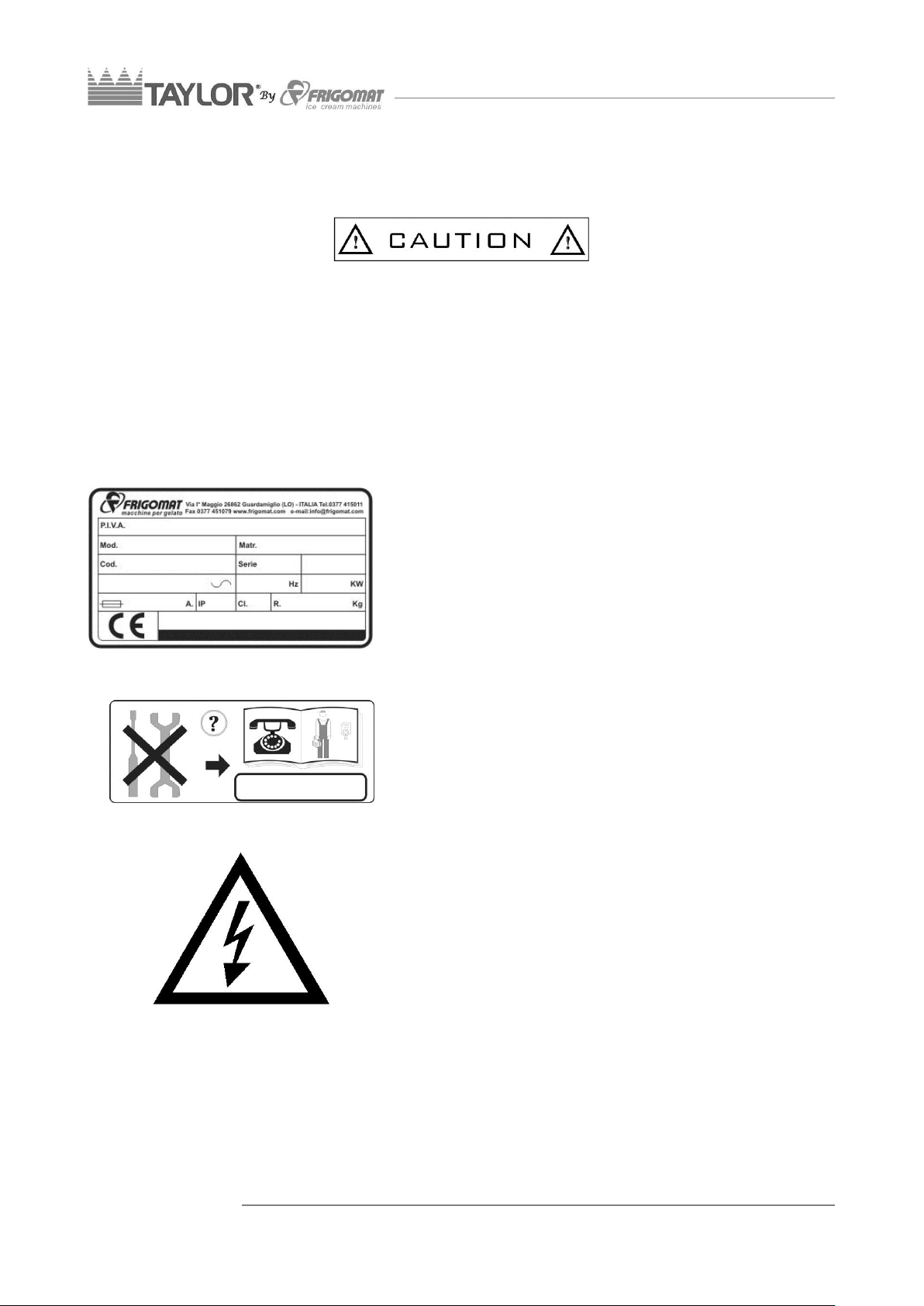
Machine data plate
The adhesive label located on the back of the
machine allows identifying the model and reports the
following indications:
Manufacturer’s name and address; Machine model
and version; Serial number; Rated electrical
characteristics; Type and weight of employed Freon;
Manufacturing year.
Warning!
Maintenance allowed to qualified personnel only.
The following plate placed on the machine back
panel forbids extraordinary maintenance operations
and/or repairs delegating them to authorized people
only, whose address is indicated in the provided
space.
Warning!
High voltage inside, danger of fulguration.
The following plate is placed on the electric box
cover and warns the operator that in no case the
cover must be removed avoiding this way the risk of
lethal fulguration. Also in this case, maintenance
operations on internal components must be
performed by authorized personnel only.
Page 7

ENGLISH - 6
3. INSTALLATION
3.1 FIELD OF USE
The batch freezers SERIES G are espressly designed and engineered for ice-cream batch
freezing cycles and for the production of granita.
3.2 LIMITS OF USE
Never use the machine with variable supply voltage and/or more than +/- 10% of the value
showed in the nameplate or when the feeder is damaged;
Do not use the machine for purposes different from the ones indicated in the present
manual;
Do not use the machine in explosive environment;
Do not wash the machine with high-pressure jets of water or poisonous substances;
Do not expose the machine to excessive heat or humidity;
Do not use completely unbalanced mixtures and/or quantities not in compliance with the
specifications reported on the packing.
3.3 MACHINE OUTFIT
- Cleaning rod
- Stiff paddle
- Manual of use and maintenance
3.4 COMMISSIONING
Bring the machine to the place of employment and check that everything is all right as far
as installation concerns:
Place the machine far from walls or other obstacles at least 10 cm and 30 on the lateral
left panel
Make sure that the supply voltage and power comply with the values reported on the
rating plate placed on the back panel;
Connect the machine to the mains; upstream the machine, arrange an omnipolar
master switch with minimum contact opening equal to 3 mm and adequate power,
interlocked with fuses to allow plugging and unplugging at open circuit.
Connect the feeder to a type-approved plug: the feeder shall be well stretched, to avoid
rolling and overlapping. It shall not be exposed to possible shocks or tampering
attempts and far from liquids, water and heat sources. It shall not be damaged,
otherwise make it be replaced by qualified personnel with another section and type
3G1,5H05VV-F before connecting the machine to the mains.
Arrange the connection of the yellow-green wire to a good earth connection.
The ideal temperature shall range between 15°C and 25°C.
The ideal humidity shall range between 30 and 60%.
- Declaration of conformity
- Certificate of guarantee
Page 8

7 - ENGLISH
4. OPERATION
4.1 CONTROLS
1. Cover
It hermetically seals the cylinder
during the working cycles it
avoids that the mix gets in
contact with powders and It can
be easily removed for cleaning
purpose.
2. Cover Pin
Maintains the cover in correct
position.
3. Security Device
It acts when the cover is lifted
and puts the machine in STOP.
By lowing the cover the machines
starts automatically.
4. Protection Condenser Grip
It avoids that the user can touch
even accidentally the condenser.
Leave at least 30 cm distance
between the grid and any other
object or obstacles.
5. Draning plug
6.Agitator
It agitates the mix permitting the
freezing of the product and the
correct volume increase by
incorporating air.
7.Scraper
Realized in atoxic material, it
scrapes the cylinder wall
guaranteeing always a perfect
product.
Page 9
ENGLISH - 8
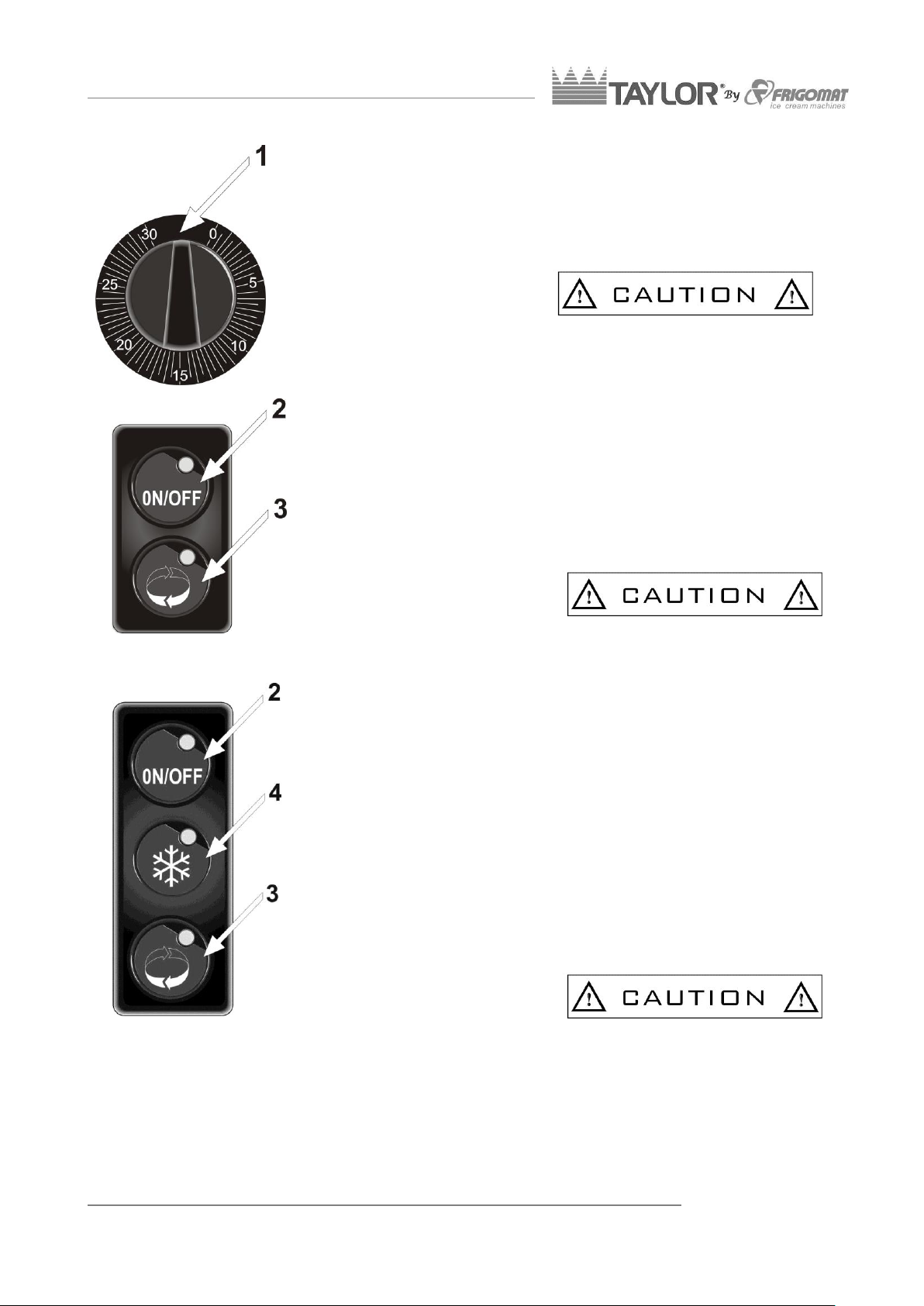
1. FREEZING TIMER
With the freezing timer it is possible to set the
production timeand consequently changing the
consistency and the look of the product.
Turning the timer you activate the compressor and you
start the production.
In order to activate the compressor and starting the
production it is necessary to change over the machine
in ON and check that the led is green
2. Pushbutton ON-OFF
With grey led, pressing the pushbutton ON-OFF, you
change over the machine in ON, the led becames
green and the continuous agitatation is automatically
activated.With green led, pressing the pushbutton ONOFF, you change over the machine in OFF, the led
becames grey and you desactived both the agitation
and the compressor.
The machine has shearing prevention system which
desactive the agitation when the cover is not
assembled or when it is not lowered. For re-activating
the agitation, verify that the cover is correctly
assembled and that it is lowered.
3. Pushbutton “cyclic agitation” for granita
With grey led, pressing pushbutton “cyclic agitation”
you change over the machine in “cyclic agitation ON”,
the led becames green and you activate the function of
agitation for the production of granita without air
incorporation.
With green led, pressing pushbutton “cyclic agitation”
you change over the machine in “cyclic agitation OFF”,
the led becames grey and you go back to the function
of continuous agitation.
In order to activated the function “cyclic agitation” it is
necessary to change over the machine in ON and
check that the led of both pushbuttons are green.
4. BUTTON “ICE CREAM CONSERVATION (for
model G10 only).
Page 10
9 - ENGLISH
MODELL
MIN (LITRES)
MAX (LITRES)
C124 1 1,5
C125 1 2,2
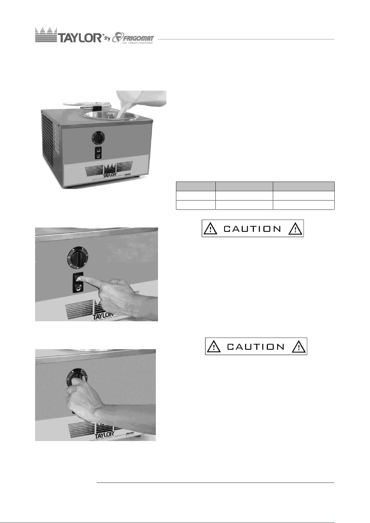
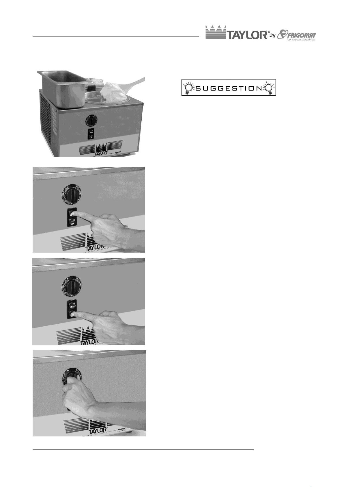
4.2 ICE-CREAM PRODUCTION
fter the machine has been installed according to
the instructions reported in chapter 3 and
carefully cleaned and sanitized according to the
instructions reported in chapter 6, proceed as
follows to start up the ice-cream production:
- Check that the master switch is closed.
- Lift the cover and pour the mixture into the
cylinder. Observe the suggested minimum
and maximum quantities per cycle according
to the following table:
The non-observance of the minimum and
maximum batch values can cause the
malfunction of the machine and, sometimes,
serious damages.
- Lower the cover and press the pushbutton
ON-OFF for starting the machine and the
agitation; verify that the led of the
pushbutton is green.
- Turn the freezing-timer on the required time.
This operation activates the compressor and
starts the production.
Remember always to set the freezing time
otherwise the freezing cycle can not start.
- Once passed the presetted freezing period
fixed by the timer the compressor stops and
the agitation keeps in function; if the
consistency is not the required one, it is
possible to set on the timer a new timevalue which guarantees an higher
consistency.
Page 11
ENGLISH - 10
It is possible to increase or decrease the
remaingin freezing period acting on the timer in
whatever moment.
- Once optained the required consistency,
stop the machine by pressing the ON-OFF
pushbutton and check that the led is grey.
Lift the cover and proceed with the
extraction of the product using the showel in
outfit.
4.3 Production of coffee-granita
The coffee-granita is a delightful speciality
which requires for its preparation a cyclic
agitation which maintains its classic dark colour.
For this reason the machine is equipped with a
special program which permits the production of
granita with a minimum air incorporation.
For selecting the program ”cyclic agitation”
proceed as follows:
- Pour into the machine the required mix as
already previously explained
- Press the pushbutton ON-OFF and verify
that the led is green
- Press the pushbutton “cyclic agitation” and
verify that the led is green. In this function
the agitator will stop for at about 57 sec. and
and works for at about 3 sec.
- Regulate the freezing timer as explained
previously in order to start the production.
- Once finished the production, desactivated
the program “cyclic agitation” by pressing
the respective pushbutton and check that
the led is grey.
- Switch off the machine and extract the
product from the cyclinder.
Page 12

11 - ENGLISH
4.4. CONSERVATION OF ICE CREAM (for
model G10 only)
The function of “ice cream conservation”
maintains the product for a long period of time at
correct temperature and consistency directly in
the freezing tank.
Thanks to this function you may decide to
distribute the ice cream according to needed
quantity and time periods .
Further more, you may add in whenever moment
fresh product to compensate the distributed
quantity.
In order to select the program “ice cream
conservation” proceed as following:
- pour the mix in the freezing tank and start the
freezing cycle as per cap. 4.2.
- in whenever moment press button
CONSERVATION (4) and check that green led is
on. Once finished the preset freezing cycle, the
machine will automatically changeover to
conservation
- During the conservation period, the beater motor
and compressor will cyclic be on in automatic
way.
- During the freezing cycle, if you lift the cover, for security reasons, the production cycle
will be interrupted and the led (5) will be on. To restart the freezing cycle, close the cover
and check that the led is off.
- During the conservation cycle, if you lift the cover, for security reasons, the beater and
compressor will stop. If the led (5) will be off, this means that the product is at correct
distribution temperature; if the led is on, this means that the product may not be at correct
temperature for the distribution of the product and therefore you have to close the cover
to bring the machine in ideal conditions.
- During the conservation cycle it is possible to increase low product quantity with fresh
mix without acting on the freezer timer. On the contrary, if the poured quantity is too
much, it may be necessary to act on the timer in order to start e new short freezing cycle.
Page 13

ENGLISH - 12
5. MAINTENANCE
5.1 ROUTINE MAINTENANCE (ADDRESSED TO THE USER)
During production, cleaning and maintenance operations, never touch the machine with
hands or tools without making sure that the machine has been disconnected from mains.
In case of troubles, make sure that they are not caused by a lack of servicing. On the
contrary, ask for the intervention of a TAYLOR customer service. In case it is necessary to
replace a piece, always ask a distributor or an authorized retailer for ORIGINAL spare
parts.
It is advisable to make the machine be checked by a Customer Service every 6/8 months.
6.1.1 CLEANING AND SANITIZATION
Bacteria and moulds easily proliferate due to the presence of fats in cream, that is why it is
necessary to carefully wash and clean all parts in contact with the product, such as the
cylinder, the agitator and the door.
Rustless materials and/or made of plastic for
food industry used for our machines, in
conformity with the most severe international
standards, make washing operations easier,
however they cannot prevent mould
proliferation, etc. caused by insufficient
cleaning.
TAYLOR recommends cleaning the tank and
the parts in contact with the product after the
employment and in any case in compliance with
the sanitary standards in force in the country of
installation. To thoroughly clean your batch
freezer, proceed as follows:
1. Switch off the machine by pressing the
pushbutton ON-OFF and verify that the led
is grey. To set to zero the freezing timer and
verify that the led of the pushbutton “cyclic
agitation” is grey.
2. Withdraw the cover pin and remove the
cover.
3. Descrew the knob and withdraw the agitator
upwards; remove the scraper.
4. Immerge the components into a cleaning
solution and wash carefully. Use the
cleaning rod in the outfit for the cleaning of
the agitator shaft.
5. Use a sponge for removing from the cylinder
the left product.
Page 14

13 - AENGLIS
6. Pour in the cylinder a little quantity of
cleaning solution. Wash carefully.
7. Use a sponge for removing from the cylinder
Rinse carefully using clear warm water. If
required repeat the operation.
8. Sanitize carefully the cylinder and all
components previously disassembled and
cleaned. Let them dry in the open air.
- To preserve plastic components and
gaskets, never use solvents and/or diluents
during washing.
- Sanitizing chemicals shall be used
according to laws in force and with the
utmost caution.
- After any sanitizing operation, it is
indispensable not to touch the sterilized
parts either with hands or with towels,
sponges or other.
- Avoid making the agitator run empty, as the
machine can be damaged.
Page 15

ENGLISH - 14
6. TROUBLE-SHOOTING
TROUBLE
POSSIBLE CAUSES
REMEDIES
the machien does not start
(pushbutton ON-OFF is activated
with green led)
master switch oper
turn the switch off
cover lifted up or not assembled
lower the cover and /or verify if it is
correctly assembled
select “cyclic agitation”
verify that the led of the
pushbutton “cyclic agitation” is
grey
incorrect power supply
verify supply
Electrical trouble.
Send a technician
Since the first phases of the batch
freezing cycle, the compressor
works intermittently
condensator dirty or fan broken
clean condensator with a brush
and verify the fuctionning of the fan
motor
The freezing period is too long and
the ice-cream is wet.
insufficient condensating
check that between the lateral left
panel and the wall or other
obstacles there is at least 30 cm
space
high ambient temperature
verify that the ambient temperature
is not higher than 25°C
too high mix temperature
The max. production of the
machine is reached using liquid
mix at 4 °C. Using mix at higher
temperature, the freezing time
becames longer, which is normal
and is not a trouble.
Worn out agitator scraper
verify and replace if required
trouble in the freezing system
send a technician
the product is too soft
insufficient freezing time
select on the timer a longer time-
period
the product is too hard
excessive freezing time
select on the timer a shorter time-
period
durino the batch freezing the
machine is noisy
presence of ice on the cylinder wall
the ice cream is ready to be
extracted
verify that the mix quantity is not
less than the required minimum
one.
the belt slip
send a technician
driving shaft bearing worn out
send a technician
Page 16

1 - APPENDICI
Modello / Model
C124
C125
Dimensioni (mm)
Size (mm)
Larghezza 431,5
Profondità 467,5
Altezza 321,5
Width 480
Depth 490
Height 340
Peso netto (kg)
Net Weight (kg)
46,8
55
Tensione di alimentazione
Supply Voltage
230/50/1
230/50/1
Potenza installata (kw) (*)
Installed Power (kw) (*)
0,7
1
Condensazione
Cooling
Aria
Air
Aria
Air
Gas
R 404 – 0,450 kg
R404- 0,425 kg
Capacità (lt)
Capacity (lt)
1,5
2,2
Produzione (kg/h)
Production (kg/h)
5
10
7 APPENDICI / APPENDICES
7.1 Dati tecnici / Machine Specification
INDICATIONS FOR DECOMMISSIONING
The machine contains electrical and/or
electronic materials and can contain fluids
and/or oil. If it needs to be decommissioned
or disposed of, comply with the standards in
force in the Country where it is used.
Even packaging materials (crates or boxes)
must be divided by type and disposed of in
compliance with standards in force in the
Country where it is used when the machine
is decommissioned.
Page 17

APPENDICI - 2
C124
C125
Page 18

3 - APPENDICI
7.2 Refrigerant circuit diagram
Page 19

APPENDICI - 4
7.3 Electric System C124
Page 20

5 - APPENDICI
7.3 Electric System C125
Page 21

6 - APPENDICI
7.4 SPARE PARTS
For spare parts ordering, always mention the corresponding code number and the name
reported on each table caption. It is also recommended to always mention the machine
model and the serial number as well as the technical data (voltage, frequency and
phases), to make the identification of the component easier. To order spare parts for the
compressor, always mention the model specified on the motor nameplate. In case it is
necessary to replace a component, always ask a distributor or an authorized retailer for
ORIGINAL spare parts. FRIGOMAT declines any liability for damages to people and/or
things due to employment of non-original spare parts.
Page 22

7 - APPENDICI
C124/s04 Tav.1/3
Page 23

8 - APPENDICI
C124/s03 Tav.1/3
P.
COD.
DESCRIZIONE
DESCRIPTION
1
L20.42381
Perno portello
Cover pin
2
P14.37569
Pomolo coperchio
Cover knob
3
E07.37566
Magnete
Magnet
4
P18.37729
Pattino raschiante
Scraper
5
E07.37565
Sensore
Switch
6
D04.104
Timer
FreezingTimer
7
E07.37511
Gruppo pulsanti
Pushbuttons
8
M02.37806
Etichetta anteriore
Lower label
9
A02.38557
Carenatura anteriore
Front panel
10
A02.37510
Pannello posteriore
Back panel
11
Z56.42733
Evaporatore completo
Complete evaporator
12
Z70.427324
Agitatore
Agitator
13
L18.37559
Pomolo agitatore
Knob agitator
14
P16.40151
Coperchio
Cover
15
B15.037
Cerniera fissa
Fixed hinge
16
P19.37838
Tappo scarico
Tank drain plug
17
P10.062
OR 2037
OR 2037
18
P10.045
OR 3100
OR 3100
19
P11.42015
Boccola
Bushing
Page 24

9 - APPENDICI
C125/s03 Tav.1/3
Page 25

10 - APPENDICI
C125/s03 Tav.1/3
P.
COD.
DESCRIZIONE
DESCRIPTION
1
L20.42381
Perno portello
Cover pin
2
P14.37569
Pomolo coperchio
Cover knob
3
E07.37566
Magnete
Magnet
4
P18.37729
Pattino raschiante
Scraper
5
E07.37565
Sensore
Switch
6
B15.037
Cerniera fissa
Fixed hinge
7
D04.104
Timer
FreezingTimer
8
M02.37806
Gruppo pulsanti
Pushbuttons
9
M02.38304
Etichetta anteriore
Lower label
10
P19.37838
Tappo scarico
Tank drain plug
11
P10.062
OR 2037
OR 2037
12
A02.37979
Carenatura anteriore
Front panel
13
A02.37597
Pannello posteriore
Back panel
14
Z56.37590
Evaporatore completo
Complete evaporator
15
Z70.40654
Agitatore
Agitator
16
L18.37559
Pomolo agitatore
Knob agitator
17
P16.40151
Coperchio
Cover
18
P10.045
OR 3100
OR 3100
19
P11.40724
Boccola
Bushing
Page 26

11 - APPENDICI
C124/s04 Tav.2/3
Page 27

12 - APPENDICI
C124/s03 Tav2/3
P.
COD.
DESCRIZIONE
DESCRIPTION
1
A03.116
Condensatore aria
Air condenser
2
B03.37488
Ventola
Fan
3
B03.37489
Staffa
Fan support
4
A01.37480
Telaio
Frame
5
P06.104
Piedino
Foot
6
D06.143
Pressacavo
Cable grip
7
A02.37514
Griglia
Grate
8
A01.218
Compressore 230/50/1
Compressor 230/50/1
9
D04.231
Condensatore avviamento
Start condenser
10
E01.37487
Motore ventilatore
Fan motor
11
E06.37700
Klixon
Klixon
12
E06.37699
Relè
Relay
13
B04.37490
Filtro
Filter
Page 28

13 - APPENDICI
C125/s03 Tav.2/3
Page 29

14 - APPENDICI
C125/s03 Tav2/3
P.
COD.
DESCRIZIONE
DESCRIPTION
1
A03.096
Condensatore aria
Air condenser
2
B03.37587
Ventola
Fan
3
B03.37092
Staffa
Fan support
4
A01.37584
Telaio
Frame
5
P06.104
Piedino
Foot
6
D06.143
Pressacavo
Cable grip
7
A02.37514
Griglia
Grate
8
E06.41895
Klixon 220/50/1 (A01.234)
Klixon 220/50/1 (A01.234)
8
E06.38621
Klixon 115/60/1 (B01.38104)
Klixon 115/60/1 (B01.38104)
9
E06.41894
Relè 220/50/1 (A01.234)
Relay 220/50/1 (A01.234)
9
E06.37582
Relè 208-240/60/1
(B01.36744)
Relay208-240/60/1
(B01.36744)
10
B04.37841
Raccogli liquido
Fluid collector
11
B04.37589
Filtro
Filter
12
A01.234
Compressore 230/50/1
Compressor
12
B01.36744
Compressore
Compressor
12
B01.38104
Compressore 115/60/1
Compressor 115/60/1
13
E06.41896
Condensatore avv. 220/50/1
(A01.234)
Start condenser 220/50/1
(A01.234)
13
E06.37580
Condensatore avv.
208-240/60/1
(B01.36744)
Start condenser
208-240/60/1
(B01.36744)
14
E01.37586
Motore ventilatore 230/50-60/1
Fan motor 230/50-60/1
14
E01.38105
Motore ventilatore 115/50-60/1
Fan motor
15
A04.37982
Staffa termostato
Brachet thermostat
16
B11.37981
Termostato
Thermostat
17
E06.37581
Condensatore di marcia
208-240/60/1
(B01.36744)
Running condenser
208-240/60/1
(B01.36744)
18
E06.38107
Relè + condensatore 115/60/1
(B01.38104)
Relay + condenser 115/60/1
(B01. 38104)
Page 30

15 - APPENDICI
C124/s04 Tav.3/3
Page 31

16 - APPENDICI
C124/s04 Tav.3/3
P.
COD.
DESCRIZIONE
DESCRIPTION
1
E01.37491
Motore agitatore 230/50/1
Beater motor 230/50/1
E01.37962
Motore agitatore 115/60/1
Beater motor 115/60/1
2
D04.216
Condensatore marcia (E01.37491)
Running condenser (E01.37491)
E06.38622
Condensatore marcia (E01.37962)
Running condenser (E01.37962)
3
L06.37492
Puleggia conduttrice
Guide pulley
4
V02.050
Vite 10X50
Screw 10X50
5
A11.37495
Cuscinetto
Bearing
6
V13.006
Dado
Nut
7
B65.37494
Tendicinghia
Belt tightener
8
L06.37493
Puleggia condotta
Guided pulley
9
B60.42725
Albero trasmissione
Driving shaft
10
P10.37496
Cinghia
Belt
11
A01.37481
Piastra motore
Support plate
12
D03.105
Relè SLCD 220 v.
(RS)
Relay SLCD 220 v.
(RS)
E08.38339
Relè SLCD 115/60/1
Relay SLCD 115/60/1
13
E01.37599
Ciclico
Ciclic
E01.38337
Ciclico 115/60/1
Ciclic 115/60/1
14
E08.37600
Relè FINDER 230/50/1 (R)
Relay FINDER 230/50/1 (R)
E08.38338
Relè FINDER 115/60/1 (R)
Relay FINDER 115/60/1 (R)
15
V14.072
Anello elastico
Seeger
16
B14.036
Cuscinetto
Bearing
17
P10.014
OR 2137
OR 2137
18
L21.41558
Distanziale
Tube
19
V14.073
Anello elastico
Seeger
20
P02.42007
OR 0250
OR 0250
21
L21.42723
Supporto
Support
22
L21.37518
Ghiera di fissaggio
Fixing nut
23
A21.41900
Rasamento
Shim
24
P21.41899
Trappola termica
Insulating support
25
L21.41891
Canotto
Transmission tube
26
L1.42251
Fermo boccola
Stop bushing
27
A11.42009
Boccola
Bushing
28
P10.067
OR 2087
OR 2087
29
L21.41892
Sede boccola
Seat bushing
30
P10.072
OR 3072
OR 3072
Page 32

17 - APPENDICI
C125/s03 Tav.3/3
Page 33

18 - APPENDICI
C125/s03 Tav.3/3
P.
COD.
DESCRIZIONE
DESCRIPTION
1
E01.37491
Motore agitatore 230/50/1
Beater motor 230/50/1
E01.37962
Motore agitatore 115/60/1
Beater motor 115/60/1
2
D04.216
Condensatore marcia (E01.37491)
Running condenser (E01.37491)
E06.38622
Condensatore marcia (E01.37962)
Running condenser (E01.37962)
3
L06.37492
Puleggia conduttrice
Guide pulley
4
V02.050
Vite 10X50
Screw 10X50
5
A11.37495
Cuscinetto
Bearing
6
V13.006
Dado
Nut
7
B65.37494
Tendicinghia
Belt tightener
8
L06.37493
Puleggia condotta
Guided pulley
9
B60.42722
Albero trasmissione
Driving shaft
10
P10.37496
Cinghia
Belt
11
A01.37481
Piastra motore
Support plate
12
D03.105
Relè SLCD 220 v.
Relay SLCD 220 v.
E08.38339
Relè SLCD 115/60/1
Relay SLCD 115/60/1
13
E01.37599
Ciclico
Ciclic
E01.38337
Ciclico 115/60/1
Ciclic 115/60/1
14
E08.37600
Relè FINDER 230/50/1 (R)
Relay FINDER 230/50/1 (R)
E08.38338
Relè FINDER 115/60/1 (R)
Relay FINDER 115/60/1 (R)
15
V14.072
Anello elastico
Seeger
16
B14.036
Cuscinetto
Bearing
17
P10.014
OR 2137
OR 2137
18
L21.41558
Distanziale
Tube
19
V14.073
Anello elastico
Seeger
20
P02.42007
OR 0250
OR 0250
21
L21.42723
Supporto
Support
22
L21.37518
Ghiera di fissaggio
Fixing nut
23
A21.41900
Rasamento
Shim
24
P21.41899
Trappola termica
Insulating support
25
L21.41891
Canotto
Transmission tube
26
L1.42251
Fermo boccola
Stop bushing
27
A11.42009
Boccola
Bushing
28
P10.067
OR 2087
OR 2087
29
L21.41892
Sede boccola
Seat bushing
30
P10.072
OR 3072
OR 3072
Page 34

NOTE / NOTES / NOTES / BEMERKUNG / NOTA
Page 35

Page 36

FRIGOMAT s.r.l., via 1° Maggio 26862 GUARDAMIGLIO (LO) – ITALIA
tel. 0377.415011 – Fax. 0377.451079
www.frigomat.com
info@frigomat.com
2018
cod. M04.37847
 Loading...