

Page 1
»
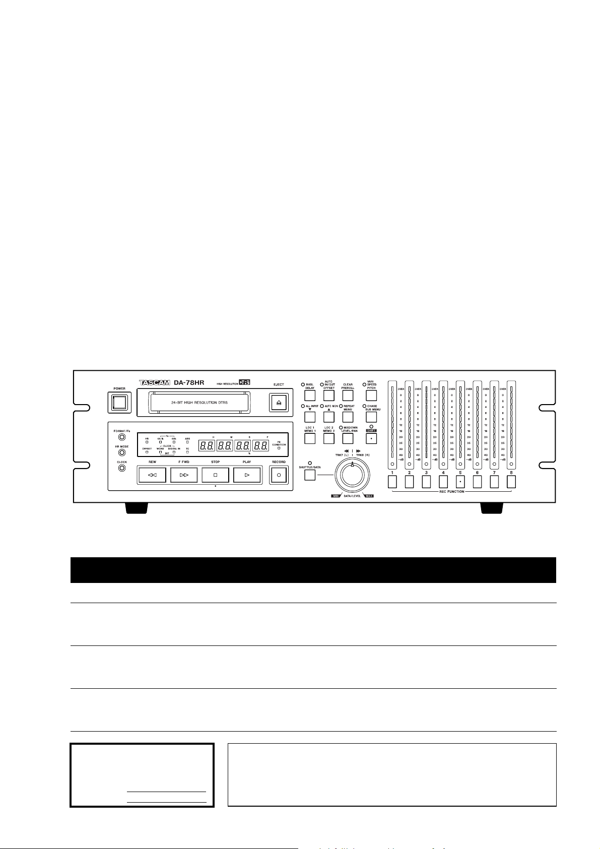
DA-78HR
Digital Multitrack Recorder
D00524000A
OWNER’S MANUAL
Ü
The lightning flash with arrowhead symbol, within an equilateral triangle, is intended to alert
ÿ
Ÿ
This appliance has a serial number
located on the rear panel. Please record
the model number and serial number
and retain them for your records.
Model number
Serial number
the user to the presence of uninsulated “dangerous voltage” within the product’s enclosure
that may be of sufficient magnitude to constitute a risk of electric shock to persons..
The exclamation point within an equilateral triangle is intended to alert the user to the presence of important operating and maintenance (servicing) instructions in the literature
accompanying the appliance.
CAUTION: TO REDUCE THE RISK OF ELECTRIC SHOCK, DO NOT
REMOVE COVER (OR BACK). NO USER-SERVICEABLE PARTS
INSIDE. REFER SERVICING TO QUALIFIED SERVICE PERSONNEL.
WARNING: TO PREVENT FIRE OR SHOCK
HAZARD, DO NOT EXPOSE THIS
APPLIANCE TO RAIN OR MOISTURE.
Page 2

Important Safety Precautions
IMPORTANT (for U.K. Customers)
DO NOT cut off the mains plug from this equipment.
If the plug fitted is not suitable for the power points in your home or
the cable is too short to reach a power point, then obtain an
appropriate safety approved extension lead or consult your dealer.
If nonetheless the mains plug is cut off, remove the
fuse and dispose of the plug immediately, to avoid
a possible shock hazard by inadvertent connection to the mains
supply.
If this product is not provided with a mains plug, or one has to be
fitted, then follow the instructions given below:
IMPORTANT: The wires in this mains lead are coloured in
accordance with the following code:
GREEN-AND-YELLOW : EARTH
BLUE : NEUTRAL
BROWN : LIVE
WARNING: This apparatus must be earthed.
As the colours of the wires in the mains lead of this apparatus may
not correspond with the coloured markings identifying the terminals
in your plug proceed as follows:
The wire which is coloured GREEN-and-YELLOW must be
connected to the terminal in the plug which is marked by the letter
E or by the safety earth symbol ç or coloured GREEN or GREENand-YELLOW.
The wire which is coloured BLUE must be connected to the terminal
which is marked with the letter N or coloured BLACK.
The wire which is coloured BROWN must be connected to the
terminal which is marked with the letter L or coloured RED.
For U.S.A
TO THE USER
This equipment has been tested and found to
comply with the limits for a Class A digital device,
pursuant to Part 15 of the FCC Rules. These
limits are designed to provide reasonable
protection against harmful interference when the
equipment is operated in a commercial
environment. This equipment generates, uses,
and can radiate radio frequency energy and, if
not installed and used in accordance with the
instruction manual, may cause harmful
interference to radio communications.
Operation of this equipment in a residental area
is likely to cause harmful interference in which
case the user will be required to correct the
interference at his own expense.
CAUTION
Changes or modifications to this equipment not
expressly approved by TEAC CORPORATION
for compliance could void the user’s authority to
operate this equipment.
For the consumers in Europe
WARNING
This is a Class A product. In a domestic environment, this
product may cause radio interference in which case the user
may be required to take adequate measures.
When replacing the fuse only a correctly rated approved type should
be used and be sure to re-fit the fuse cover.
IF IN DOUBT — CONSULT A COMPETENT ELECTRICIAN.
Pour les utilisateurs en Europe
AVERTISSEMENT
Il s’agit d’un produit de Classe A. Dans un environnement
domestique, cet appareil peut provoquer des interférences
radio, dans ce cas l’utilisateur peut être amené à prendre
des mesures appropriées.
Für Kunden in Europa
Warnung
Dies is eine Einrichtung, welche die Funk-Entstörung nach
Klasse A besitzt. Diese Einrichtung kann im Wohnbereich
Funkstörungen versursachen ; in diesem Fall kann vom
Betrieber verlang werden, angemessene Maßnahmen
durchzuführen und dafür aufzukommen.
2
TASCAM DA-78HR
Page 3
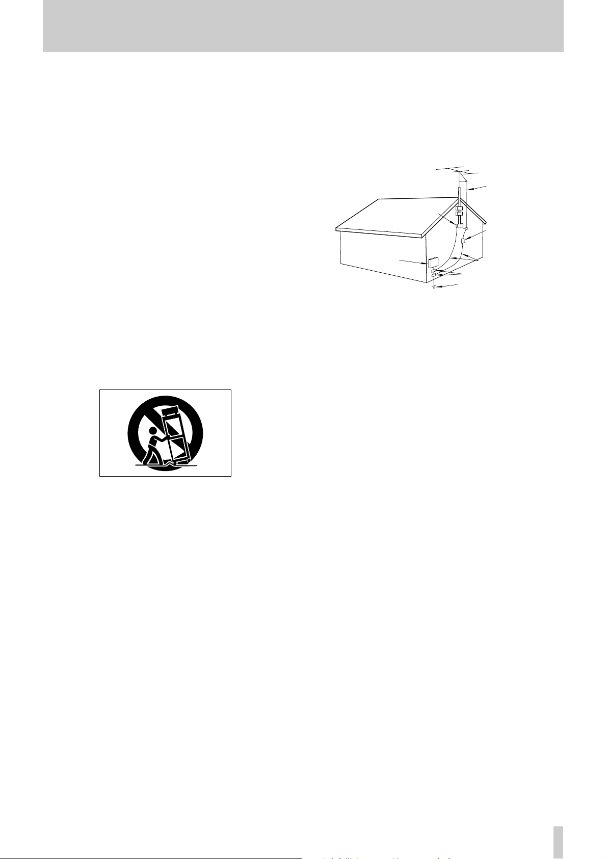
ANTENNA
LEAD IN
WIRE
ANTENNA
DISCHARGE UNIT
(NEC SECTION 810-20)
GROUNDING CONDUCTORS
(NEC SECTION 810-21)
GROUND CLAMPS
POWER SERVICE GROUNDING
ELECTRODE SYSTEM
(NEC ART 250. PART H)
NEC - NATIONAL ELECTRICAL CODE
ELECTRIC
SERVICE
EQUIPMENT
Example of Antenna Grounding as per
National Electrical Code, ANSI/NFPA 70
GROUND
CLAMP
IMPORTANT SAFETY INSTRUCTIONS
CAUTION:
Read all of these Instructions.
Save these Instructions for later use.
Follow all Warnings and Instructions marked on the audio
equipment.
1) Read Instructions — All the safety and operating instructions should
be read before the product is operated.
2) Retain Instructions — The safety and operating instructions should
be retained for future reference.
3) Heed Warnings — All warnings on the product and in the operating
instructions should be adhered to.
4) Follow Instructions — All operating and use instructions should be
followed.
5) Cleaning — Unplug this product from the wall outlet before cleaning.
Do not use liquid cleaners or aerosol cleaners. Use a damp cloth for cleaning.
6) Attachments — Do not use attachments not recommended by the
product manufacturer as they may cause hazards.
7) Water and Moisture — Do not use this product near water — for
example, near a bath tub, wash bowl, kitchen sink, or laundry tub; in a wet
basement; or near a swimming pool; and the like.
8) Accessories — Do not place this product on an unstable cart, stand,
tripod, bracket, or table. The product may fall, causing serious injury to a
child or adult, and serious damage to the product. Use only with a cart,
stand, tripod, bracket, or table recommended by the manufacturer, or sold
with the product. Any mounting of the product should follow the manufacturer’s instructions, and should use a mounting accessory recommended by
the manufacturer.
A product and cart combination should be moved with care. Quick stops,
excessive force, and uneven surfaces may cause the product and cart combination to overturn.
10) Ventilation — Slots and openings in the cabinet are provided for ven-
tilation and to ensure reliable operation of the product and to protect it
from overheating, and these openings must not be blocked or covered. The
openings should never be blocked by placing the product on a bed, sofa,
rug, or other similar surface. This product should not be placed in a built-in
installation such as a bookcase or rack unless proper ventilation is provided
or the manufacturer’s instructions have been adhered to.
11) Power Sources — This product should be operated only from the
type of power source indicated on the marking label. If you are not sure of
the type of power supply to your home, consult your product dealer or local
power company. For products intended to operate from battery power, or
other sources, refer to the operating instructions.
12) Grounding or Polarization — This product may be equipped with a
polarized alternating-current line plug (a plug having one blade wider than
the other). This plug will fit into the power outlet only one way. This is a
safety feature. If you are unable to insert the plug fully into the outlet, try
reversing the plug. If the plug should still fail to fit, contact your electrician
to replace your obsolete outlet. Do not defeat the safety purpose of the
polarized plug.
13) Power-Cord Protection — Power-supply cords should be routed so
that they are not likely to be walked on or pinched by items placed upon or
against them, paying particular attention to cords at plugs, convenience
receptacles, and the point where they exit from the product.
14) Outdoor Antenna Grounding — If an outside antenna or cable
system is connected to the product, be sure the antenna or cable system is
grounded so as to provide some protection against voltage surges and builtup static charges. Article 810 of the National Electrical Code, ANSI/NFPA
70, provides information with regard to proper grounding of the mast and
supporting structure, grounding of the lead-in wire to an antenna discharge
unit, size of grounding conductors, location of antenna-discharge unit, connection to grounding electrodes, and requirements for the grounding electrode.
"Note to CATV system installer:
…
…
…
9)
This reminder is provided to call the CATV system installer’s attention to
a)
b)
c)
d)
e)
Section 820-40 of the NEC which provides guidelines for proper grounding
and, in particular, specifies that the cable ground shall be connected to the
grounding system of the building, as close to the point of cable entry as
practical.
15) Lightning — For added protection for this product during a lightning
storm, or when it is left unattended and unused for long periods of time,
unplug it from the wall outlet and disconnect the antenna or cable system.
This will prevent damage to the product due to lightning and power-line
surges.
16) Power Lines — An outside antenna system should not be located in
the vicinity of overhead power lines or other electric light or power circuits,
or where it can fall into such power lines or circuits. When installing an
outside antenna system, extreme care should be taken to keep from touching such power lines or circuits as contact with them might be fatal.
17) Overloading — Do not overload wall outlets, extension cords, or
integral convenience receptacles as this can result in risk of fire or electric
shock.
18) Object and Liquid Entry — Never push objects of any kind into
this product through openings as they may touch dangerous voltage points
or short-out parts that could result in a fire or electric shock. Never spill
liquid of any kind on the product.
19) Servicing — Do not attempt to service this product yourself as open-
ing or removing covers may expose you to dangerous voltage or other
hazards. Refer all servicing to qualified service personnel.
20) Damage Requiring Service — Unplug this product from the wall
outlet and refer servicing to qualified service personnel under the following
conditions:
when the power-supply cord or plug is damaged.
if liquid has been spilled, or objects have fallen into the product.
if the product has been exposed to rain or water.
if the product does not operate normally by following the operating
instructions. Adjust only those controls that are covered by the operating
instructions as an improper adjustment of other controls may result in
damage and will often require extensive work by a qualified technician to
restore the product to its normal operation.
if the product has been dropped or damaged in any way.
f ) when the product exhibits a distinct change in performance – this
indicates a need for service.
21) Replacement Parts — When replacement parts are required, be
sure the service technician has used replacement parts specified by the
manufacturer or have the same characteristics as the original part.
Unauthorized substitutions may result in fire, electric shock, or other
hazards.
22) Safety Check — Upon completion of any service or repairs to this
product, ask the service technician to perform safety checks to determine
that the product is in proper operating condition.
23) Wall or Ceiling Mounting — The product should be mounted to a
wall or ceiling only as recommended by the manufacturer.
24) Heat — The product should be situated away from heat sources such
as radiators, heat registers, stoves, or other products (including amplifiers)
that produce heat.
TASCAM DA-78HR
3
Page 4

Table of Contents
1 - In troduction to th e DA-78HR
1.1 Unpacking.........................................7
1.2 Features.............................................7
1.3 Using this manual............................. 7
1.4 Precautions and recommendations 8
1.4.1 Clock source in a digital studio.......8
1.4.2 H R rec or din g an d emp ha si s.... .... ....8
1.4 .3 Environment al conditions ............ ....8
1.4.4 Installing the DA-78HR.....................9
1.4.5 Ele ctr ic al c onsid e ratio ns......... ........9
1.4.6 Three-core power cord.....................9
1. 4.7 Power i ng the DA-78HR off and on... 9
1.4.8 C on de n sation. .... ......... ..... ......... ........9
1.5 Recommended tapes........................9
1.5.1 T ape brands.... ......... ......... .... ......... ....10
1.5.2 Available recording and playback
time...........................................................11
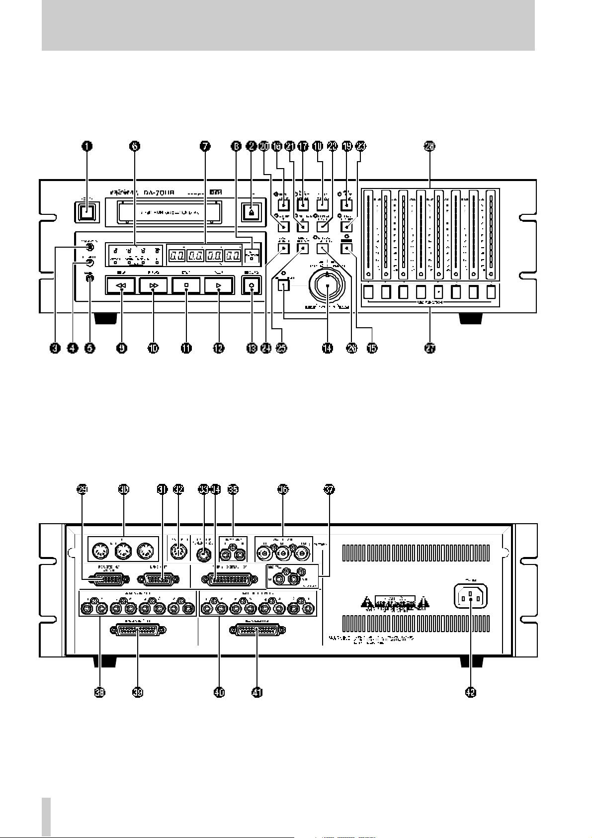
2 - Front an d r e ar pan el features
2.1 General controls and indicators......13
Power switch ........................................13
1
Tape loadin g s lot and EJ ECT ke y ......13
2
FORMAT/Fs k ey ................................... 13
3
HR MODE key .......................................13
4
CLOCK key ...........................................13
5
Status indicators ..................................13
6
Tape counter ........................................13
7
PB CONDITION indicator ....................13
8
2.2 Tape transport keys and controls ...13
REW key ...............................................13
9
F FWD key ............................................13
A
STOP key ..............................................14
B
PLAY key ..............................................14
C
RECORD key ........................................ 14
D
DATA/LEVEL control ...........................14
E
2.3 System cont rol keys.........................14
SHIFT key a nd in dicator ......................14
F
RHSL (DELAY) key and indicator ....... 14
G
AUT O IN/O UT (OFFSET) key and
H
indicator .................................................. 14
CLE AR (PRE ROLL) key ......................14
I
VARI SPEED / PITCH ke y and
J
indicator .................................................. 14
ALL INPUT (▼) key and indicato r ...... 14
K
AUTO MON (▲) key and indica tor ......14
L
REPEAT (MENU) key and indicator ....15
M
CHASE (SUB ME NU) key a nd
N
indicator .................................................. 15
LOC 1 (MEMO 1) key ............................15
O
LOC 2 (MEMO 2) key ............................15
P
MIXDOWN (LEVEL/PAN) key and
Q
indicator .................................................. 15
2.4 Track controls................................... 15
REC FUNCTION keys and indicators . 15
R
Peak meters .......................................... 15
S
2.5 Rear panel fe a tures...........................15
REMOTE IN/SYNC IN ............................15
T
M IDI IN/OUT/THRU ................................15
U
SYNC OUT . .... ..... .... ......... ......... ..... ........15
V
REM OTE IN ... ..... .... ......... ..... ......... .... ....15
W
REMOTE PUNCH IN/ OUT .....................16
X
TDIF-1 (DIGITAL I/O) .............................16
Y
TIME CODE (IN, OUT) ...........................16
Z
W ORD SYNC (IN , OUT, THRU) ............16
a
DIGITAL IN, OU T (COAXIAL) ...............16
b
ANALOG INPUTS ( unbala nced) ..........16
c
ANALOG INPUTS ( BALANCED) ..........16
d
ANALOG OU TPU TS (unba la nc ed ) .. ....16
e
ANALOG OUTPUTS (BALANCED) ......16
f
~ IN .........................................................16
g
3 - Conn ect ions
3.1 Audio connections............................17
3. 1.1 Bala nce d analog audio conne ctions17
3. 1.2 Unbala nce d analog audio
connecti ons .............................................1 7
3. 1.3 Digital aud io conne ctions.................17
3.1.4 SPDIF c o nnect ors .... ......... ......... .... ....18
3.2 Synchronization connections..........18
3. 2.1 W or d clock connections...................18
3. 2.2 MIDI connect or s (IN , OUT and
THR U) .......................................................18
3.2.3 Ti meco de c onne ct ion s..... .... ..... .... ....18
3.2 .4 MIDI timecode connections.......... ....18
3.3 Connection to other T ASCAM units18
3.3.1 RE MOTE IN. ..... ......... .... ......... ..... ........18
3.3.2 Foot sw itch .. ..... .... ......... ......... ..... ........18
3.3.3 Multiple DTRS units...........................18
3.3.4 “In direc t” word sy nc........ ......... .... ....19
4 - Menu in t erface, etc.
4.1 The display........................................20
4.1.1 Pea k m et ers......... ......... ..... ......... .... ....20
4.2 The SHIFT key...................................20
4.2.1 Shif ted ke ys ..... .... ......... ..... ......... .... ....20
4.2.2 Shif t mode....... ......... ......... .... ......... ....20
4.3 Menus and sub -menus.....................21
4.3.1 Exiting menu mode............................21
4.3.2 Sub -men us...... .... ......... ..... ......... .... ....21
4.3.3 Adjus ti ng para meter val ues . ......... ....21
4. 3.4 Reset ti ng para m eter s to default
value s .......................................................21
4.3.5 “Left” and “right” key s......................22
4.3.6 Sub -fra me v alue s..... ......... ......... .... ....22
4. 3.7 Using the DATA/LEVEL knob to set
value s .......................................................22
4.4 SYSTEM menu...................................23
4.5 AUDIO1 menu....................................23
4.6 AUDIO2 menu....................................24
4.7 TC menu.............................................24
4
TASCAM DA-78HR
Page 5

Table of Contents
4.8 TC chase menu..................................25
4.9 TC ge nerator menu...........................25
4.10 MIDI menu........................................25
4.11 Maintenance menu..........................26
4.12 Dedicated keys................................26
5 - Basic operat ions
5.1 Formatting a tape..............................2 7
5.1.1 Selecting a word clock source........ 27
5.1.2 Form at ting..... ..... ......... .... ......... ..... ....27
5.1.3 Aborting the format proce ss............2 8
5.1.4 Reco rding while forma ttin g......... ....28
5.2 Recording the first tracks.................28
5.2.1 Preparing to record...........................28
5.2.2 Selecting a clock source ..................28
5.2.3 Write -pro t ecti ng casse tte s.. .... ..... ....28
5.2.4 Reco rding t he fir st trac ks (i)............29
5.2.5 Recording the basic tracks (ii).........2 9
5.2.6 Replaying the first trac ks.................2 9
5.3 Input selection...................................29
5. 3.1 Digital input s election....................... 29
5.3.2 In put p a tchb ay routing ... ..... .... .........30
5.3 .3 Track bouncing........... ......... ............. 30
5.3.4 Returnin g to ALL ANALOG setting. 31
5.4 More on digita l recording.................31
5. 4.1 Sampling freque ncy and word
leng th.......................................................31
5.4.2 Selecting input word length............. 31
5.5 Overdubbing......................................31
5.6 Punch-in and punch-out...................32
5. 6.1 Automatic punch poi nt setting........ 32
5. 6.2 Setting punch points “on the fly”.... 32
5. 6.3 Setting punch points usi ng the front
panel.........................................................33
5. 6.4 Editing the pre-r oll a nd post-roll
times.........................................................33
5.6.5 Reh ea rsing the punc h-in..... ......... ....34
5. 6.6 Interrupt ing a rehears al or punch
rec ording .................................................34
5.6.7 Reco rding t he punc h -in .. ..... ......... ....34
5. 6.8 Repla ying the punched material......34
5. 6.9 Exiting punch-in mode. .................... 35
6 - Monitoring
6.1 ALL INPUT.........................................36
6.2 AUTO MON.........................................36
6.3 Shuttle monitor..................................36
6. 3.1 Enabling and disabl ing shuttle
monitoring............................................... 36
6.4 Shuttle muting ...................................36
6.5 Summary of monitor modes ............37
7 - Advanced op erations
7.1 Autolocation......................................38
7.1.1 Setting M EMO 1 and MEMO 2 “on
the fly” ......................................................38
7.1.2 Checking, editing and manually
entering MEMO 1 and MEMO 2...............38
7.1 .3 Setting t he loc ation pre-roll time .....38
7.1 .4 Moving t o MEMO 1 and MEMO 2......38
7.1 .5 Location and playbac k ......................38
7.2 Re peat function .. ................... ............39
7.2 .1 To start repea t play ...........................39
7.3 Tra ck delay............................. ............39
7.4 Su b-mixer............ ................... ............40
7.4 .1 Entering mixdown mode...................4 0
7.4 .2 Setting t he master level ....................40
7.4 .3 Leaving edit/pan setting mode.........40
7.4 .4 Setting levels and pan positions......4 0
7 .4.5 Set ti n g the sub- m ix er inpu t s o ur ces 41
7.5 Cr os sfade t imes................................41
7.6 Vari speed (pitc h control).................41
7.6 .1 To set a non-standard speed............41
7.7 Sh uttle oper atio ns................. ............42
7.7 .1 Shu ttle monitoring .............................42
7.7 .2 Shu ttle muting...................................42
7.8 M ete r mod es.......................... ............42
7.8 .1 Peak hold time...................................42
7.8 .2 Meter ballis tics ...................................42
7.9 Sin e oscillat or..... ................... ............43
7.9 .1 Recording the osc illator ...................43
7.10 REC MUTE (recording silence)......43
7.11 Dither................................................43
7.1 1.1 Selectin g dit her settings.................44
7.12 Advanced output options...............44
7.1 2.1 Output word length .........................44
7.1 2.2 Output patchbay ..............................44
7.13 Emulat ion.........................................45
7.14 Saving settings to tape...................45
7.15 Restoring settings from tape .........45
8 - Synchroniza tion with other DTRS
units
8.1 Syn chr oniz ati on co nnections ..........47
8.2 Machine ID and master/slave
settings..................................................47
8.2.1 Differ enc es betw een DTRS m odels . 47
8.2 .2 Setting machine ID ............................4 8
8.2.3 Master/slave settings (CHASE
mode)........................................................48
8.3 M achine off set.... ................... ............48
8.3 .1 Setting machine offs e t......................48
8.3 .2 Can celling machine offset................48
8.3.3 Setting machine offset “on the fly” .49
8.3 .4 An example of setting offsets ..........49
8.4 Digit al du bb ing ... ................... ............50
8.5 Syn chr oniz ed formatting..................50
TASCAM DA-78HR
5
Page 6

Table of Contents
8.5.1 R ecordi ng while fo rm at ting. ..... ........51
8.6 Individual clock mode...................... 51
8.7 Error messages.................................51
9 - Op erations related to time code
9.1 ABS and timecode............................52
9.1.1 A BS t ime......... ......... .... ......... ..... ........52
9.1.2 T ape timec ode............. ..... ......... ........52
9.1.3 Sel ec ting TC or ABS ti ming ..... ........5 2
9.2 Tape timecode mod e........................52
9.2.1 TAPE TC sett ing................................ 53
9.2.2 A BS se ttin g......... ......... ......... ..... ........5 3
9.3 Selecting the frame mode................53
9.4 Timecode input and output..............53
9.4.1 Showing input timecode...................54
9.4.2 Timecode input timing......................54
9.4.3 T imeco de o ut pu t ..... .... ......... ..... ........5 4
9.4.4 MTC out pu t ..... .... ......... ..... ......... .... ....54
9. 4.5 Fa st linear timecode (LTC) output... 55
9.4.6 Timecode output timing ...................55
9.5 Recording timec ode......................... 55
9.5.1 Sel ec ting the ti mec ode sourc e.... ....55
9.5 .2 R eco rd ing timeco de u sin g t h e
ge nerato r ......... ..... .... ..... .... ..... .... ..... .... ....56
9.5.3 Gene rat or mode s........ ......... ......... ....56
9.5 .4 Synthes izing timecode from ABS
timin g...... ......... ......... .............. ......... ........56
9.5.5 External timecode sources .............. 57
9.5 .6 R eco rd ing timeco de f r om exte rn al
s ources... ..... .... ..... .... ..... .... ..... .... ..... .... ....57
9.5.7 Checking external timecode ............ 57
9.5.8 Checking the frame mode of striped
timecode.................................................. 58
9.6 Chasing to timeco de ........................58
9.6.1 Machine ID and timecode.................58
9.6.2 T imeco de o ff set . ..... ......... .... ......... ....58
9.6.3 Setting timecode offset ....................58
9.6.4 Cancelling timecode offset ..............59
9. 6.5 Setting timecode offset “on the fly” 59
9.6.6 Par k p osi ti on .. ......... .... ......... ..... ........59
9.6.7 Automatic park positio n s e tting ...... 59
9.6.8 A bs o lut e a n d r elat ive d iffe renc e.. ....60
9.6.9 R echa sing t ime cod e... ......... ..... ........60
9.6.10 Bypassing timecode errors............ 60
9. 6.11 Indi vidual recording while chasin g
timecode.................................................. 60
10 - MID I control
10.1 MMC enable and disable................62
10. 1.1 A ss ig n in g a MIDI I D to the
DA -78HR.. ..... .... ..... .... ..... .... ..... .... ..... .... ....62
10.1.2 MMC commands and the DA-78HR62
10.2 MMC Bit Map Array.........................63
10.3 MIDI Control Change......................65
10.4 MIDI System Exclusiv e...................65
10.4.1 Id e nt it y Re p ly.... ......... ..... ......... .... ....65
10.4.2 T ASCA M E xc lusiv e message s.......65
10.4.3 T rack dela y........ ..... ......... .... ......... ....65
10.4.4 C ross fad e . ......... ..... ......... ......... .... ....65
10.4.5 M ac hine o f fset........ .... ......... ..... ........65
10.4.6 T rack Copy Se tup.. .... ......... ......... ....66
10.4.7 T rack Copy En abl e............. ......... ....66
10.5 MIDI Implementation Chart............67
11 - Mainte nance, etc.
11.1 Head and tr a nsport cleaning .........68
11.1.1 To clean the heads and transport..68
11.1.2 Che cking error rates........................68
11.1.3 Che cking drum time........................69
11.2 Backup memory initialization........69
11.3 Checking version numbers............69
11. 3.1 Software upgrades .... .............. ........70
12 - O ptions, spec ificat io ns and ref eren ce
12.1 Options for the DA-78HR................71
12.1.1 R C-8 98 remote cont ro l u nit..... .... .... 71
12.1.2 R C-8 28 remote cont ro l u nit..... .... .... 71
12.1.3 R C-8 08 remote cont ro l u nit..... .... .... 71
12.1.4 IF-AE8 AES/EBU digital audio
converter..................................................71
12.1.5 IF-88SD SDIF-2 digit al audio
converter..................................................71
12.1.6 IF-TA D ADAT digita l a ud io
converter..................................................71
12.1.7 TDIF- 1EX extender box...................71
12.1.8 C able s... .... ......... ......... ..... ......... .... ....71
12.2 Spe cific ations........................... .......72
12.2.1 T ape rec ord er sect ion.... .... ......... ....72
12.2.2 A nalog i nput s and output s ..... ........ 72
12. 2.3 Digital inputs and outputs .......... ....72
12. 2.4 Remote/ sync connectors ............ ....72
12.2.5 W ord sync termi n als . ..... ......... .... ....72
12. 2.6 Timecode connec tors..... ............. ....72
12.2.7 M IDI conne cto rs..... ......... ......... .... ....72
12. 2.8 Remote contr ol connectors.... ........72
12.2.9 Phy sic al spec ifica t ion s .. ......... .... ....73
12.2.1 0 P ower spec if ica tio ns.... ......... ........73
12.2.1 1 Au dio s pec ifi ca tions..... .... ..... ........ 73
6
TASCAM DA-78HR
Page 7

1 - Intr oduction to the D A-78HR
Th e TASCAM DA-78HR is a digital audio multitrack recorder designed for use in a variety of applica ti on s, i nclu di n g vi d e o po st-produ c ti on an d audi o
multitr ack work.
It r ecords 8 tracks of full-q uality digital audio on
standard Hi8 video cassettes using a speciallyde sig ned trans port and head mechanis m. Using this
medi um, up t o 108 minute s of c ontinu ous re co rding
is possible on a single NTSC “120” tap e
Recording is carr ied out at either 24 or 16 bits of resoluti on, and digi t al data may b e input at 16, 20 or 24
bits o f resolution. An alog signals are conver te d to
digital da ta usi n g 64 t i mes over s am pl i n g de l ta - si g ma
techniqu es.
The DA-78HR bu ilds on the foundation s laid by the
TASCAM DA-88, DA-38 and DA-98 digital multitrac k rec orders, and retains compat ibility wit h them.
16-bit tapes record ed on on e of the DA series can be
r eplayed and overdubbed on any other machi ne in the
series, or any DTRS
be replayed in DA-78HR recorders,
1
machine. 24-bit ta pes can only
1.1 Unpacking
The box contains the following.
• DA-78HR Digital Multitrac k Recorder (x 1)
• Accessories:
–Ra ck mount screw ki t (x 1)
–AC power cord, 2 m (6 ft.) long (x 1)
–T his m anu al (x 1)
• Warran ty card (x 1)
1.2 Feat ures
Other key features of the DA-78HR include:
• TASCAM-exclusive high- performance/high wear
resistive rotary 4-head mechanism with TASCAM
original track la yout (DTRS standard )
• Use of stand ard, low-cost media with lon g record ing and playback times
• 24 - bit or 16-bit linear quantization a t either 44.1
kHz or 48 k Hz provides C D-quali ty s ound or bett er
• Fa st, frame-a ccur a te tape location and positioning;
end-to-end winding for a “120” tape is around 80
seconds
1. DTRS is a tradema rk of TEAC Corporation
• Direct digital synchronization of up to 16 DTRS
recorder s (128 tracks) without the use of any ex ternal synchronizer or controller
• Direct digita l dubbing b etween DTRS units
• A n inte rna l digita l patchbay, allowing input-totrack assignment and selection of digit al, analog
an d off-tape sources without the use of external
sw itc hing or routing equipme nt
• I nternal 8 x 2 mixer (lev el an d pan) for stereo
replay of recorded tracks and ou tput through a
stand ard SPDIF connec tor without ex ternal m ixing
equipm ent
• SPDIF stereo input
• Balanced +4dBu analog inputs and ou tputs carried
on a convenient compact D-sub connector
• Un balanced –10 dBV connectors (RCA) for conne ction to semi-pro fession al equipmen t
• 15 -seg men t p eak meters with u ser- selec table f al l
ba llistics and variable hold time (includin g continuous peak hold)
• Meters also used fo r display of channel and track
information
• Inte gra l digita l sin e oscillator, providing signals at
440Hz and 1kHz for tuning and other frequencies
for lineup purposes
• D igital in put a nd output on a single convenient
compact D-sub connector (T DIF-1 format)
• Settings carr ied out through a menu hie rarchy
• SM PT E /EB U timecode input and output
• MI DI Time Code and MIDI Machine Control
• Simplified source/tape monitoring functio ns with
au tomat ic switching
• Auto punch-in and punch-out with rehearsal mode
• 2-point full functio n autolocator with A– B r epeat
function.
• Variable speed reco rding and playback (up to 6.0%
in 0.1% steps)
• Shuttle m ode enables “rock and roll” audio positionin g of key locations
• D ata e ntry mode allows use of shuttle knob to set
da ta va lues
1.3 Using this manual
We suggest that you take the trouble to r e a d this manual thro ugh a t least once before s tarti ng to us e the
DA-78HR. I n th is way, yo u will find out where to
tur n when you need answers.
TASC AM D A- 78 HR
7
Page 8

1 - Introductio n to the DA-78HR
We sugg est that yo u make a speci al n ote of the section 1.4 , “Precautions and recommendations” as
the se cont ain some informati on which is unique to
the DA-78HR.
We also sugges t that you also read , a s this will help
you when you come to perform basic operations.
When r eferring to a control or a connector on the
DA-78HR, the name of the control or conne ctor w ill
be written in bold type, and ma y be followed by a
number, as in the exam ple belo w:
Ho ldi ng d own the
REC
the
D key w ill st art the reco rdi ng pr o-
PLAY
key C and pressing
cess.
The num bers refer to the front a nd rear panel illustr ations and description in this manual.
When referring to a word or phrase which appears on
the display, the word or phrase wi ll be written as
foll ows:
MEMO. 1 (
ME MO 1
).
If on -scree n p ara meter s are giv en as p art of a d isplay
example, they m ay sometimes be shown in the following way, where the
;; represents an unknown
value:
ID SEL ;; (
ID SEL xx
), where xx is the
m achine ID
NOTE
Reco rding is an a rt a s well as a scien ce. A successf ul r ecord ing is often judged primarily on the qua l ity
of sound as art, and we obviously cannot guarantee
that. A company that makes paint and brushes for
artists cann ot say that the pain t ings made with their
pr od ucts will b e critically well-receiv ed. TASCAM can
mak e no g ua rantee t ha t the DA-78HR by its elf will
assure the quality of the recordings you make. Your
skill as a tech nician an d your ab iliti es as an artist will
be significant fact ors in the results you achieve .
1.4 Precautions and recommendations
As with any precision piece of electronic equipment,
common-sense precautions apply with the DA78HR.
However, there ar e a few extra precautions which
ap ply to the DA- 78 HR, and we suggest that you
ma ke a note of the se, to prolong the useful life of the
DA-78HR.
1.4.1 Clock source in a di gita l studio
The DA-78HR can be used in a variety of s ituatio ns,
and wi th a v ar iety of equipment, either d i gital o r analog.
If you are working with more than one d igital audio
unit in yo ur s etup, you should n ote that all units must
be driven by the same central clock so urce (“word
clo ck” or “word s ync ”) .
If differ ent word clock sources are used throughout
the setup, it is actually possible to damage speake rs,
etc. becaus e of m ismat ches.
The DA-78HR can be desi gnated as the wor d clock
master for your studio, or can be slaved to external
word cl ocks, us i ng a convenient fro nt-pan el swit ch
and standard BNC co nnectors.
Even though AES/EBU stereo digital audio signals
are sel f -clocking, any AES/E BU fo rmat signals con verted and fed to or from the DA-78HR mus t be synchron ized a t word level with the DA-78 HR.
1.4.2 HR re cording an d emphas is
R ec ordings ma de in 24-bit (HR) mode do not use
emphasis.
If an attemp t is made to record a digita l signal that
contains emphasis u sing either the TDIF or the
SPDIF digita l a udio in puts, the display shows
E EM P
EMP (
), and the sig nal is muted.
E
A di gi tal emp hasis circui t is pr ovi ded, however, for
co mpa tibility w ith previous models of DTRS
recorder.
No te that if a rec ording using emphasis is dubbed to
the DA-78HR via the analo g inpu ts, this signal will
need t o be mo difi ed a ppropriatel y.
1.4.3 Environmenta l conditions
The DA-78HR can be op erated in most enviro nments, but we suggest th at you keep the environm ental conditions within the followin g limits:
• Ambient temperatu re between 5°C and 35°C (41°F
and 95°F).
• Relative humidity should be between 3 0% and
80% non-con den s in g
• There should be no strong magnetic fields (speakers, etc.) near the DA-78HR.
• Avoid spra ying polish, insecticides, etc . near the
DA-78HR.
NOTE
If you need to clean the DA-78HR, use a soft cloth,
moistened if necessary with a little detergent and
8
TASCAM DA-78HR
Page 9
1 - Intr oduction to the DA-78H R
water. Do not use abra sive cleaner s or solvents such
as alcohol or thinner.
Avoid subjecting the DA-78HR to jol ts, sudden
shocks, etc.
NOTE
— IMPOR TANT
If you have to return the unit fo r ser vice or r epair, use
t he original packing materials if pos sible. If the un it i s
to be transported to a recordin g location, etc., use a
suitable transport case with sufficient shock
protection.
TASCAM does not accept r esponsibility for damag e
resu lting from neglect or accident .
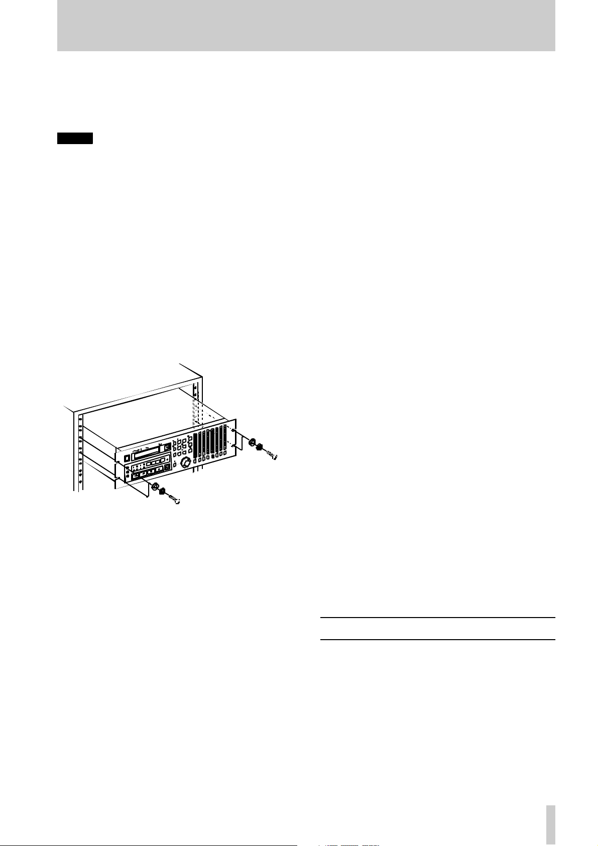
1.4.4 Installing t he DA - 78HR
T he DA -78HR ma y be inst all ed in a s tandard 19”
rack, occu pying 3 U of space. Since the DA-78HR is
quite h eavy (around bet ween 7 and 8 kg – ab out
16lb.), your rack should be strong and stable to take
the weight of the DA-78HR.
The D A - 78 H R sh ou l d be m o un te d wit h th e fron t
pane l verti cal .
1.4.6 Three-core power cord
In orde r to mainta in the best possib l e audio quali ty,
the DA- 78H R is supplied with a 3-core (grounded)
power cord. DA-78HR should be used wi th a
grou nded po wer cor d, connected to a suitable electrical groun d, at all times. If it is not, ther e is a possibility that the audio quality will suffer.
1 .4.7 Po w ering the DA-78HR off and on
When powering the DA-78H R off and on, al ways
wait for five seconds or more between powering the
unit off and tu rning it on ag ain. If the power is
switched t oo quickly, the precision power supply
may no t provide the po wer of the prop er quality
required for record ing .
If power is inadvertently swit ched o ff a n o n quick ly,
an d t he po w er su pply do e s no t res p on d pr o pe r l y ,
switch the unit off again, wait f or five or more seconds, and swi tch i t on again.
1.4.8 Condensati on
If you use the DA-78HR in a warm place after mo ving it from a cold place (for instance, recor ding on
location), or if there has been a sudden change in
temperature, condensation m ay occur within the tap e
mechanism, with a risk of possible dama ge to the
unit.
1.4.5 Ele ct rica l co nside rat ions
Make sure th at your local power supply matches the
voltage requirements marked o n the rear pa nel of the
DA- 78HR.
If you are in any doubt co ncerning the local power
supply, consult an electrician .
Av oid ex treme v oltage fluctuation s. If necessary, use
an input voltage regulator to smooth the power supplied to th e D A-78HR.
Do not open the unit to clean inside, or to per for m
any in ternal adjustm ents . Yo u sh ould not attem pt any
cleaning or other maintenance proced ures which are
not d escribe d in this manual.
Yo u may need to clean the heads occasi onally. Th e
procedure for doing this, and for checking tape error
r ates, etc. , is given in 11.1 , “Head an d transport
cleaning”.
If condensation does occur, you will not be able to
operate the DA- 78H R controls, a nd you will see the
following me ssage on the display
E DEW (
E DEW
).
If you see the above messag e, leave the DA- 78HR
s wi t ched on for o ne or tw o ho urs, then sw i tc h i t of f
an d on ag a i n before starti ng rec or d i ng .
If you are going to use the DA-78HR in a location
where you think condensation is likely to occur,
move th e DA-78HR into the warmer location a bout
one or two hours before recor ding is d ue to start, and
leave it switched on. T urn the DA- 78H R off and th en
on again bef ore starting recor ding.
1.5 Recommended tapes
Th e D A-78HR is designed for us e w ith Hi 8 vid eo
casset t es. Y ou ca nnot u s e a n y ot h e r ki n d of t a pe w it h
the DA- 78H R.
Alwa ys use new tapes, or tapes in the best possible
condition, in o rder to achie ve the best possible r esults
when recording. Tapes which have been over-used
will no t give such good resu lts as ne w tape s.
TASCAM DA-78HR
9
Page 10
1 - Introductio n to the DA-78HR
There are two basic ty pes of Hi8 tape: MP and ME.
Eac h has its ow n particular char acteristics and merits :
• MP tap es are manufactured using a d aubed magnetic particle deposit proc ess and exhibit a level of
perfor mance which is more than acceptable. They
have a durability which all ows them to be used as
work tapes in st udi o an d post -producti on
environme nt s.
• ME ta p es have the i r magneti c la yer p rod uc ed
through a metal ev apo ration process. Generally
speaking, th ough these tape s hav e a high p erformance level, they are not as robust as MP tapes (see
above ) and s hould be us ed fo r l ive recordin g and
archival purpo ses, rath er than as work tapes.
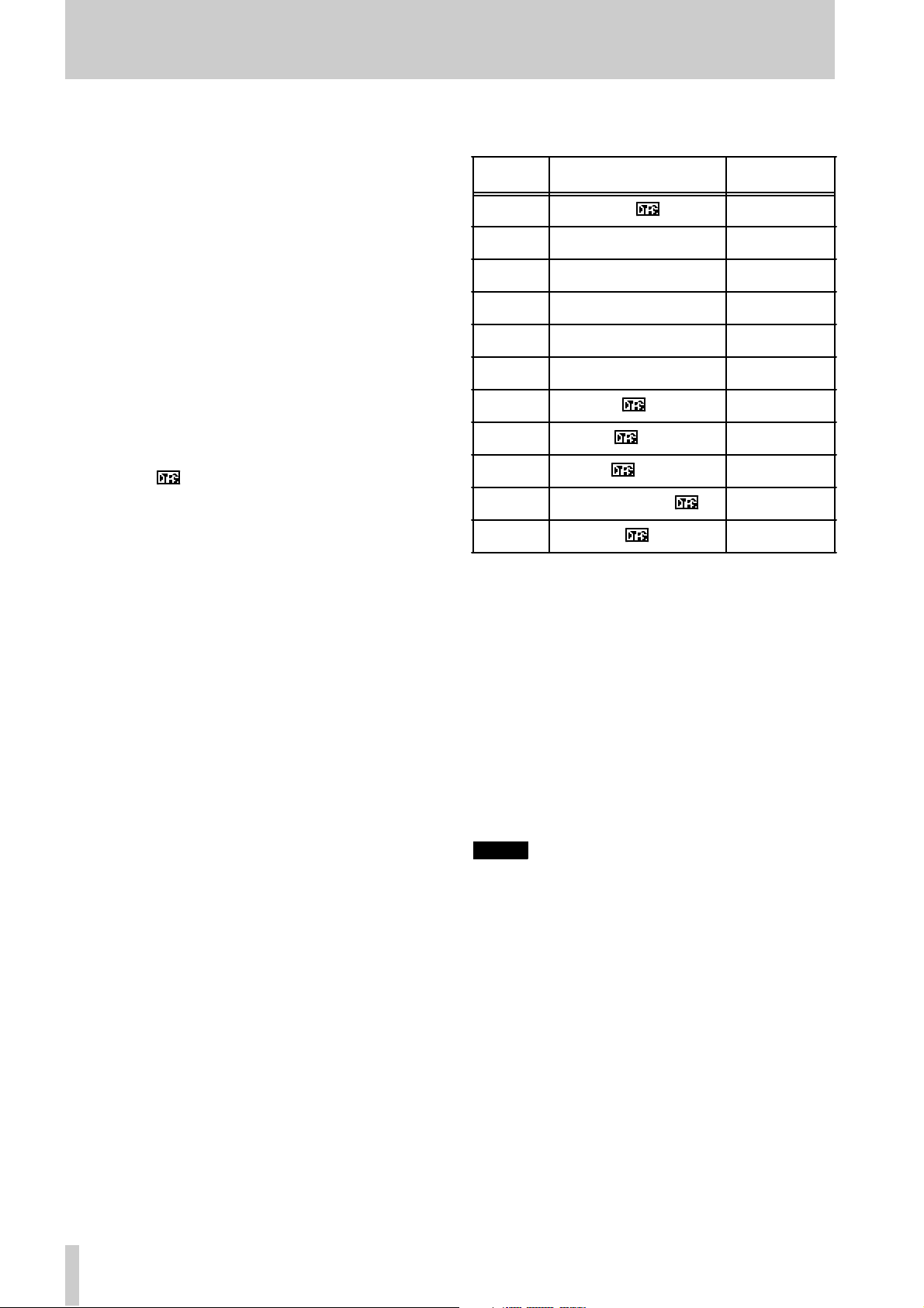
TASCAM does not endorse any specific tape or tape
manufacturer. TASCAM has licensed th e use of the
DTRS logo ( ) to tape manu fact ure rs, provided
their tape meets the specifications required by DTRS
tap e recorders. The table below lists several suc h
tap es, certified for use w ith DTRS tape record ers.
However, the use of the DTRS logo on the tape packaging d oes not imply any endors ement of the tape by
TASCAM. It is possible that the characteristics and
s ensitivitie s of tapes may be changed by the ma nuf acturers with out notice. The bra nds and mode l nu mbers of tapes listed below may not always meet the
specifications required by DTRS sy stems for o ptimum performance. TASCAM assumes no responsibility for pr oblems r esulting f rom change s made by a
ma nufactu rer to the materials or specifications of its
ta pe prod uct s .
The electr ical characteristics of DTRS r ecorders are
adjusted and set using Sony Hi8 tape parameters (MP
an d ME) prior to shipme nt.
1.5.1 Tape brands
T he follow ing bra nds and models of tape ca n be use d
with the DA-78H R. As mentioned above, this list
does not constitute any endorsem ent by TASCAM of
these prod ucts, nor is it a gu arantee t hat tapes b earing
this brand and model nam e will continue to give optimu m per formance.
Maker MP ME
Sony DARS-MP E6-HME
P6-HMP E5-HME
P6-HMPX E6-HMEAD
P5-HMP E5-HMEAD
P5-HMPX E6-HMEX
E5-HMEX
Quantegy DA8 MP
BASF DA MP
HHB DA113
Maxell DRS-113DA (P)
Fuji DPD-MP
The electr onics of DTRS recorders are designed to
operate within specific parameter s. The use of a tape
with se ns itivity higher or lower than that of ta pes for
wh ich th e DTRS recorder was originally designed
ma y cause an error in fu nctio nality or prevent the
user from gettin g optim um performa nce from the
tap e. Always use the shorte s t poss ible t ape for a
given project. Do not attempt to use 150-minute or
longer tapes in DTRS machines, as the machine will
detect the thick ness of tape and automatically eject
any tape thinner than r ecommended.
Never attempt to use a tape with the DA-7 8HR that
has previously been used in video equipment.
NOTE
— IMPOR TANT
You cannot cut and spl ice DTRS 8mm tapes for editing purposes. Using a spliced tape in the DA-78HR
will inv ar iably result in serious dama ge to the heads,
requiring replacement. All editing must be done digitally .
10
TASCAM DA-78HR
Page 11

1 - Intr oduction to the DA-78H R
1.5.2 A vailabl e recording and playback time
De pendin g on whe t he r t he t ape has be en purch a se d
for use with an NTSC (P6/E6) or a PAL/SECAM
(P5/E5) television sys tem, the same length of tape (as
far as video length is concerned) will provide different times for audio work, as shown below, d ue to di ffere nt fr a me rates betwe en televisi on syst ems. The
indication P6/E6 or P5 /E 5 will be printed on the ta pe
package:
Time on tape
label
20 18 25
30 27 37
45 40 56
60 54 75
90 81 113
120 108 –
P6/E6 (NTSC
tape)
P5/E5 (P AL/
SECAM tape)
TA SCAM DA-78HR
11
Page 12
2 - Fr ont and r ea r panel feat ur es
12
TASCAM DA-78HR
Page 13

2 - Fr ont and r ea r panel feat ur es
2.1 General contro ls and ind icators
Power switch
1
Turns the power to the DA-78HR on and off. When
the DA- 78HR is turned of f, settings will be r etained
in mem ory.
T ape loading slot and EJECT key
2
Only us e Hi8 ME or MP tapes as specified in 1.5,
“Reco mme nde d tapes”. The DA-78HR will automatically eject all other tapes .
NOTE
—IMPORTANT
Do not use a tape whi ch has been used for recording
video. Always use either new tapes or tapes which
have been used in a DTRS recorder.
EJECT
The
can only be ejected when the transport is stopped.
3
FORMAT/Fs
The
an d allows selection of the sampling frequency used
for recording (see 5.1, “Formatting a tape” for full
de tails) . The current sa mpling fre que ncy is shown on
the status indicators
4
Thi s key allows the selec tion of the recording resolution (16-bit or high-resolution 24-bit). See 5.1, “Forma tting a tape” for details.
key ejec ts an y loaded cassette. A casset te
FORM AT /Fs key
key controls the formatt ing of tapes
6.
HR MODE key
Legen d Meaning Section
OFFSET
CLOCK (WORD)
C LOCK
(DIGI TAL IN )
TAPE TC
Tape cou nter
7
M achine or tim ecode o ffset is in
operation
W hen both of these are lit, the
DA-78HR is using internal w ord
sy nc , and w hen nei t her is lit,
w ord sync is being re ceived
through the
SYNC IN
li t, t he wor d s y nc is being
r ec eive d t hrough t he ap propri-
ate connector (digital audio
COAXIAL
(
Lights when the DA -78HR is
reading time code fro m the tape
REMOTE IN/
connector. If one is
) or wor d sync).
8.3.1 an d
9.6.2
3.2
9
Th e tape counter gives th e current tape time in hours,
minutes, seconds and f rames.
I t is also use d to disp lay menus, sub-m enu s and the
va lues of the parameters of the unit, as we ll a s p roviding in forma tion on the current status of the unit.
PB CONDITION indicator
8
There is one mor e indicator:
PB CO ND I T I ON
, w h ic h
l ights if there are many errors when reading or
recording the tape. It also f lashes when the block
error rate is being check ed (11.1 .2, “Checking error
rates”).
If this lights frequently, the bloc k er r or rate can be
checked and the head s cleaned (11.1, “Head and
tr ansp or t cl eaning ”).
The app r opriate indicator 6 will light if the HR
mode is selec te d.
CLOCK ke y
5
This is used to select the word sync source for the
DA-78HR (either internal,
shown on the indicator
Status indicators
6
6).
WORD
DIGITAL IN
or
, as
The status indicators show the current status of various DA-78HR functions. The legends of these indicators are abbreviat ed for r eason s of space. Here is a
lis t of their full me a nings, toge ther with the pages on
wh ich the function s are more fully described:
Legend M eaning Section
HR
Fs (44. 1k)
Fs (4 8k )
ABS
High-reso lut ion (2 4-bit) m ode 5.1
Either of these wi ll light to sho w
the current samp ling fre quency
Tape s ubcode (ABS ) is bein g
used as the t iming reference
5.1
9.1
2.2 Tape transport keys and
controls
REW key
9
Rewinds the tape at high speed.
If this key is pressed during recording, recording will
s top and the tape will rewind.
F FWD k e y
A
Winds the tape forwar d at high speed.
If this key is pressed during recording, recording will
s top and the tape will win d forward .
NOTE
Wh en ei th er
time after powerin g up, or load ing a ta p e, the u nit first
confi gures itself for the r eel hub diameter of the tape
in use, during which the tape advances at low
speed s. This takes several seconds. Thereafter, t he
REW
or
F F WD
is pressed for the first
13
TASCAM DA-78HR
Page 14

2 - Front and rear pan el features
transport momentarily goes into stop mode before
the tape sta rts fast-winding.
STOP key
B
Cancels any current tape transport mode, and sto ps
the tape. I f pressed in chase mode, can cels the mode
and stops the tape.
PLA Y ke y
C
Starts playing the tape. If this key pr e ssed w hile
r ecording is in progress , t he DA -78HR drops ou t of
record mode.
RECORD key
D
PLAY
If the
ke y is held down , recording will start on all “armed”
tracks (5.2. 1, “Prep aring to record”).
If the DA-78HR is in play mode, and the
pressed, recording will start immediately on any
“armed” tracks.
RECORD
The
during auto punch-in/out operations (5.6, “Punch-in
and punch-out”).
E
When the
tor will lig ht. The
active as a shuttle control. Turning the control to the
right provides forw ard c uein g and turning it to the
left provides reverse cuei ng, similar to “rock and
roll” o n open-r eel tape decks. For details, see 7.7,
“Shuttle o per ation s”.
When the
tio n with th e
also used as a data entry control to make vario us settings, in c lud ing the sub-mixer settin gs. See 4.3.7,
“ Usin g the DATA/LE VEL knob to set values” and
7. 4, “Sub-mixer” for details.
key C is pressed w hile the
k ey also is used to set punch-in poin ts
DATA/LEVEL co ntro l
SHUTTLE/DAT A
DATA/LEVEL
SHUTTLE/DA TA
SHIFT
ke y, t h e
key is pr esse d, the indica-
key is pr essed in c onjunc -
DAT A /L E VEL
control will th e n be
RECORD
REC
key is
control is
2.3 Syst em con trol keys
SHI FT key and ind icato r
F
C o nt ro l s th e be h a vi o r of th e ot h er keys (s e e 4.2, “Th e
SHIFT key” for details).
R HS L (D E L AY ) key and i nd ica t o r
G
This ke y an d indicator a llow selection of the
rehearsal mode in auto punch-in and out (5.6,
“Pun ch-in and punch-o ut”).
When the DA- 78H R is in shift mode, this key allo w s
the setting of tra ck d e la ys (7.3, “Track dela y”).
AUTO IN/OUT (OFFSET) key and
H
indic ator
This ke y and indic ator allow automatic punch-in and
punch out foll owing r ehears al (5. 6, “ P unc h-in an d
punch-o ut”).
When the DA- 78H R is in shift mode, this key allo w s
the setting of chase offsets (8.3, “Mac hin e offset”
and 9.6.2, “Timecode offset”).
CL E AR ( P RE ROLL ) key
I
T his k ey d efeats the rehearsal and au to modes during
au t o punch -i n a n d out (s e e 5. 6 , “ P un ch-in and punc hout”) . It can also be used to canc el a fo rmat o perat ion
(5.1, “Fo rmatting a ta pe”).
When the DA- 78H R is in shift mode, this is used to
set pre- and post-roll times (5.6.4, “Editing the preroll and post-roll times” and 7.1.3, “Setting the location pre- roll time”).
V ARI SPEED / PI T CH key and
J
indic ator
Used to set the varispeed (pitch) amoun t, and to turn
the function o n and off (see 7 .6, “Vari speed ( pitch
control)”.
AL L I NP UT (▼) key an d i ndicat or
K
This ke y is used to switch the monitoring mode so
that the o utputs mirro r the inputs (see 6.1, “A L L
INPUT”).
The following keys all pr ovide access to more
adva nced funct ion s of the DA- 78H R. M any o f t hem
are also u sed in the menu system to v iew and set system parameters. See 4, “Menu in terface, etc.” for
de tails.
M any of them als o serve two func tions, as shown by
the blue “shifted” legends below the uns hifte d legends (shown here in parentheses). See 4.2, “The
SHIFT key” for details.
AUTO MON (▲) key and in di cator
L
This ke y is used to c hange the monito ring mode to
change automatically in punch operations (see 6.2,
“AUTO MON”).
In menu mode and when editin g parameters, th is acts
as a key to select and change (increm ent) parameters .
SHIFT
When used with the
key.
key, it acts as a cursor
TA SCAM DA-78HR
14
Page 15

2 - Fr ont and r ea r panel feat ur es
REPEAT (MENU) key an d indicator
M
Th is key is use d to provi d e a r e pe at fu nc t ion be tw e en
the two location points (see 7.2, “Repeat function” ).
Wh en the D A-78HR is shift mode, it allows s election
of the to p-level men us (se e 4. 3, “Me nus an d s ubmenus”).
CH ASE (SUB M E NU) key and
N
indicator
This k ey is used to set the DA-78HR to a slave chas e
mode , eithe r to another DTRS unit, or to timecode
(see 8.2.3 , “Master /slave settings (CHASE mode)”
and 9. 6 , “Chasing to timecode”) .
W hen the D A-78HR is in shift mode, it allows selection o f the second level o f men us in the menu tree
( s ee 4.3, “Menus a nd sub-menus”).
LOC 1 (MEMO 1) key
O
This k ey locates the tape to the position set by
1
(this key used with the
“Autolocation” for details.
LOC 2 (MEMO 2) key
P
This k ey locates the tape to the position set by
2
(this key used with the
“Autolocation” for details.
MIXDOWN (LEVEL/PAN) key an d
Q
SHIFT
key). See 7.1,
SHIFT
key). See 7.1,
MEMO
MEMO
indicator
T his key turn s the 8 x 2 sub-m ixer ou tput on and off
fro m the re ar pan e l outp ut s. See 7 .4, “Sub -mix er” fo r
details.
W hen the DA-78HR is in shift mode, this key is u sed
to set the level a nd the pan po sitio n of each track in
the sub-mixer image (7.4, “Sub- mixer ”) .
2.4 Track controls
REC FUNCTION keys a nd indicators
R
Thes e eight switches and indicators allow the se tting
and viewing of the record status o n a track -by-track
basis.
When one of these switches is pressed, the appropriate indicator will flas h, the track is “armed” , and
goin g into record mode will start recording on that
track. When rec ording is being car ried out on a track,
the track’s indicator will light steadily.
In ad dition, these keys are also used to selec t tracks
and channels for different operations, including the
input an d out put patchbays, the delay and su b-mixe r
f unc tions. See 7.3, “Tr ac k de lay”, 7.4, “Sub- mi xer ”
an d 5.3, “Input selection” for de tails of these
operations.
Peak me t ers
S
Th e se 15-segment peak meters show the input leve l
or the recorded signal level, depending on the monito ring mo de currently in operation ( 6, “Monitoring”).
NOTE
When using digi tal recor ding equipment, there is no
headroom above the 0 dB mark and no tape saturation is possible. Any signal which causes the “OVER”
segment to ligh t will cause audible di s tortion. For this
r eason you should ta ke care not to let recording levels exceed this level.
The ballistics and peak h old times are selectable (s ee
7.8, “Meter mo des”).
T hey may als o be used to prov ide a qui ck visua l
guide to the s tatus of some of the s ettings ( sub- mixer ,
patchbay, etc.). See 4.1.1, “Peak meters” for details.
2.5 Rear panel features
See 3, “Connections” for full details of how to connect the DA-78HR to other units.
RE MO TE IN/SY NC IN
T
This connector is us ed to connect another “master”
DTRS un it (e. g. DA-78HR, DA- 98, DA-8 8 or DA-
38). See 8, “Synchronization with other DTRS units”
for further details.
A TASCA M remote control un it may also be conne cte d here, but not all f unctions of the DA- 78HR
ma y be ava ila ble from the remote control un it.
MID I IN /OU T/TH RU
U
These conne ctors carry MIDI Time Code (MTC) and
MMC ( MIDI Mach in e C ontrol) comm ands as well as
MIDI System E x clusive mes sages. See 10, “MIDI
co ntrol” for details o f how these fa c ilities a r e used
wh en synch ronizin g to other units.
SYNC OUT
V
Th is is used to connect another DTRS unit in the
“d aisy-chain” or, if this DA-78HR is the last unit in
t he chain, to attach a termination plug.
REM OTE IN
W
Us e this to connect an optional RC-808 remote contr ol unit . No te that no t all feat ures of the D A- 7 8HR
can be cont rol led using the R C-808.
15
TASCAM DA-78HR
Page 16

2 - Front and rear pan el features
REM OTE P UNCH IN/ OUT
X
Use this to connect an optional RC-30P footswitch to control punch operations.
TD IF - 1 (DI GITA L I/O)
Y
This connector carr ies the digital signals to and f rom
the DA- 78HR in TEAC Digital I nterface Format
(TDIF-1).
T IME CODE (I N, O UT)
Z
These RCA connectors are used to carry SMPTE/
EBU timecode to an d fro m the D A-78HR. For details
of using th e DA -78 HR with timeco de synchronization, see 9, “Ope r a tions related to timecode ”.
WORD SYNC (I N, OUT, THRU )
a
These BNC connectors are used to carry the word
cl ock b et w ee n the DA-78H R and oth e r ty pe s of di g i tal audio equipment. The
terminated (i.e . there is no need for a terminator
when this is unconnected).
DIGITA L IN, OUT (COAXIA L)
b
These RCA connectors provide an SPDI F stereo digital audio signal containing the submi x signal (
or accept an SPDIF signal (
“Sub-mixe r ” and 5.3.1, “Digita l input selection” ).
THRU
connec to r is auto-
IN
) for recording (see 7.4,
OUT
ANALO G I N PUTS (unbal a nced)
c
These eight RCA connectors accept unbalanced analog audio inputs at –10 dBV.
ANA LOG INPUTS (BALANCED)
d
Th is conne ctor c ar ri es 8 balanc ed inputs at a nomina l
+4 dBu level. This allows convenient an d reliable
single-cable connection to th e GROUP outputs of a
suitably-equipped console such as the TASCAM M1600 series.
ANALOG OUTPUTS (unbalanced)
e
These eight RCA connectors output unbalan ced analog audio signals at a – 10 dBV level.
ANA LOG OUTP UTS (BALANCED)
f
This connector carries 8 balanced outputs at a nominal +4 dBu l evel. This all ows conven ient and reliable
single-cable connec tion to the tape return inputs of a
suitably-equipped console such as the TASCAM M1600 series.
~ IN
g
Use the provided AC power cord to connect the DA-
)
78HR to the A C power supply through this
connector.
TA SCAM DA-78HR
16
Page 17
3 - Connections
This section explains how to connect other equipme nt to the DA-78HR. It is not inte nde d as a complete ref erence to the use of the DA-78HR. See the
appropriate sections for f ull details of h ow these connectors are used.
NOTE
S—IMPORTANT
When making connec tions bet ween the DA-78HR and
other equipment, w hether audio or control, both the DA78HR and the other equipment m ust be turned
wise damage may be caused to t he DA-78HR and/or the
other equipment .
Only use T ASC AM-supplied and TASCAM-approved
cables when m aking connections to the DA-78HR. T hough
the cables and connec tors may resemble computer cables,
they serve dif ferent purpos es, and meet a dif ferent set of
specifications. The use of cab les other than TASC AM
cables will at best c ause the equipment t o work errat ically,
and at w orst c ause damage to the equipment .
If the use of cables other than TASCAM cables
causes or results in damage, the warranty i s voided.
off
, other-
3.1 Audio connections
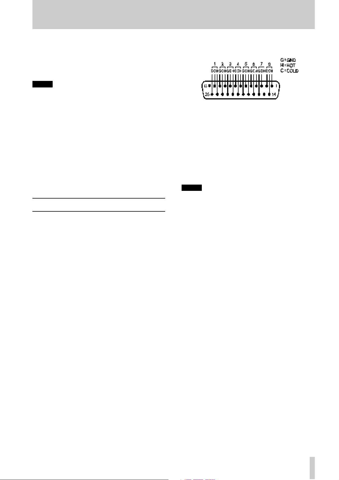
T he pinouts for bo t h t he
INPUT
co nnect ors are as follows:
G
where
=ground, H=”hot” (+) a n d C=”co ld” (–).
ANALOG OUTPU T
and
The i mpedance of the inp uts i s 20kΩ and that of the
outputs is 10Ω.
3.1.2 U n balance d analog audi o connections
In add ition to th e balan ced an alog set of co nnection s,
ther e are eight RCA jacks f or input signals and eight
for o utput. These are, of co urse, unbalanced , and the
nominal signal level is –1 0 dBV.
NOTE
On ly c onnect and u se o ne s et of analog input s at a
time. There is no fac ility to swit c h b etween the two
sets of ana log inp ut connectors.
Other audio equip ment can be connected to the DA78HR eith er using analog or digital interfaces.
Se lection for the input so urce ( analo g or d ig ital) on a
global or individual track basis is made from the
menus. See 5.3, “Input sel ect io n” for de t ail s .
3.1.1 Balance d an alog audio conn ection s
All balanced analog input and output aud io connections to the DA-78HR are made through 25-pin Dsub con necto rs.
All th ese audio inputs and outputs are balanced and
are rated at a nominal + 4dBu level.
Th is allows convenient and tidy cabling between the
DA- 78HR and oth er units su ch as the T A SCA M M1600 series of mixing consoles .
I t is not recomm end ed that you m ake up your own
cables—con sult you r TASCAM dealer for availability of sui table ready-made cables ( and see 1 2.1.8,
“Cables”). However, we recognize that every situation has its own unique features, and there are occasions when a special cable m ust be made.
Before starting to m ake the cable, we suggest you
contact your T ASC AM de aler for full deta ils of cable
specifications, etc.
3 .1.3 Digital audi o connect ions
Multitrack digital audio input and ou tput signals are
carr ied on a single 2 5-pin D-sub connector. The signals are in TDIF-1 format.
To carry signals between a DA-78HR and another
unit eq uipped with TDIF-1 in terfaces , such as the
TA S CAM serie s of digital mixing console s or othe r
DT RS recorders , u se a PW-8 8D cable (1 me t er lo ng)
or a PW-88DL cable (5 meters long).
If you need to connect the DA- 78HR to a digital
audio sour ce using a dif fer ent format , we recomm end
the us e of the following units:
• TASCAM IF-88AE Interface Unit—converts
between the TDIF-1 an d AE S/E B U f orma t s
(8 cha nne ls). It also provides SP DIF f ormat
conversion fa c ilities.
• T ASCAM IF-AE8—also provides sophisticat ed convers i on facilities be tween the TDI F-
1 and AES/EBU data fo rmats.
• TASC AM IF-88 SD Int erf ace Un it—converts
between the TD IF-1 a nd S DIF-2 digital audio
formats.
• The TASCAM IF-TAD—converts betw een
the T DIF-1 and A DAT data formats, using a
dig ital optical input/output for th e ADAT d ata.
TASCAM DA-78HR
17
Page 18

3 - Connect i ons
3.1.4 SPDIF connectors
The coaxial RCA dig ital audio connector s on the rear
panel all ow co nnecti on of an SPD IF-equip ped device
(e.g. a DAT recorder).
This digital unit sho uld be us ed as a clock source if
data is to be read fro m it
When synchronizi ng to the signal received at the
COAXIAL DIGITAL IN
DIGITAL IN
the
indicator lights.
, set the
CLOCK
key so that
3.2 Synchronizat ion connectio ns
The DA-78H R h as facilities for contro l and synchroniz ation with other units. For full details of how to
operate the DA-78HR with other units, see 8, “Synchroniz ati on w ith othe r DTRS units” and 9, “Operations related to timecode” .
3.2.1 Wo rd clo ck connection s
This set of BNC connectors is used to synchronize
the DA-78HR to other digital audio devices.
CLOCK
The
so ur c es , a n d sh ou l d be set t o
nizing to an exter nal word clock (the
tor will light).
k ey is us ed to change between clock
WORD
when s ync hro-
WORD
indica-
3.2.3 Timecode connections
The DA-78HR can be synch ronized t o extern allygenerated timecode and is also equipp ed with an
inte rna l timeco de gen erato r.
S MPTE/EBU timecod e can be received at the
CODE IN
TIME CODE OUT
RCA jack , an d can be transmitted f r om the
RCA jack.
TIME
See 9, “Ope r a tions r elated to timecode” for details.
3.2.4 MID I timec od e conne ct ions
The thre e
MIDI
connecto rs, IN,
form to the MIDI standards for such connectors.
OUT
and
THRU
, con -
3.3 Connection to other TASCAM units
By a “TASCAM unit”, we mean anoth er DA-7 8HR,
a DA-98, DA-88 or a DA-38 unit, or an optional
remote control unit, which may also be connected in
a “chain ” with multiple DTRS units.
3.3.1 REMOTE IN
This jack on the rear panel can be used to conn ect a
remote control unit such as RC-808 remote control
uni t.
IN
jack should be connected to the WORD
The
SYNC OUT of the digital audio device from which
the DA- 78HR is to rec eiv e th e synchronization c lock.
OUT
Th e
fro m the D A-7 8HR, w hile the
signals received at
outputs word clock information provided
IN
THRU,
.
to echoes the
No te that if the DA-78HR is connected to other
DTRS u nits, the
W ORD SYN C
jacks do not need to
be connected between th e DTRS u nits.
3.2.2 MIDI conn ect ors (IN , O UT and THR U)
These standard 5-p in DIN MIDI connectors are used
to carry MID I T im e C o de (MTC) and MIDI Mach ine
C ontrol (MMC) informatio n be tween the DA-78HR
and ot he r sui t ably- equipped units (for inst ance,
sequencers capable of being synchronized to MTC,
an d capab le of transmitting MMC commands).
The MI DI parameters are set through the menu
system (see 10, “MIDI control”).
Note the di f ference b etween
TH RU
. Th e
OUT
connector outputs signals which
MIDI OUT
originate f rom the DA-78HR. The
echoes mes sages received at the
IN
THRU
.
MIDI
and
connecto r
B asic c ontrol can be carried out using this unit, but
more advanced ope rations will not be possible.
3.3.2 Footswitch
A footswitch such as the o pt ional TASCAM RC-30 P
footswi tch can be co nnected to th e
IN/OUT
jack on the rear panel.
REMO T E PUNCH
This footswitch allows hands-free punch-in and
punch-out.
When a track o r track is arm ed, and the unit is in play
mod e, pr essing the foots witch o nce will drop the unit
into re c ord mode , and pressing it again will drop it
back into play m ode.
Th e footswitch , rather than the transport keys, can
als o be used to set punch points, as described in 5.6,
“Punch-i n and punch-out”.
3. 3. 3 Multiple DT RS units
Use a TASCAM P W-8 8S cable when co nnect ing
other units to the
SYNC OUT
the
Th is sy nchro nization c able will carry the internal
synchronization code and the transport s ignals, etc.
There is no need to make any other connections,
REMO T E/SYNC IN
connecto r.
connec tor or to
18
TASCAM DA-78HR
Page 19
3 - Connections
ap art from the audio connections (either digital o r
analog).
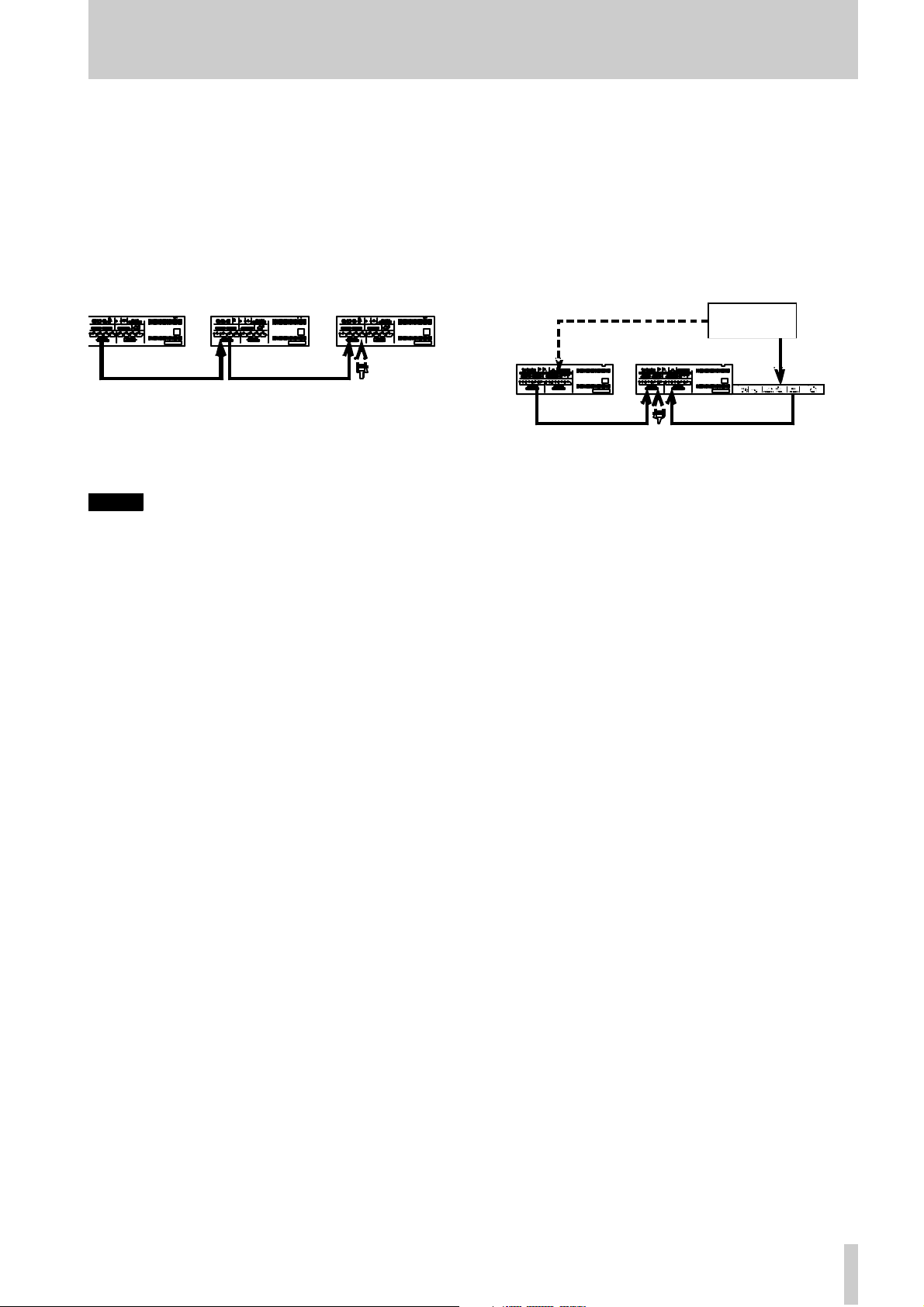
If more than one DTRS unit is to be used, the first
unit in the chain mu st ha ve its Machine ID set to “1 ”,
(“0” in the case of DA-88s) and subsequent units
mus t have their IDs se t in o r der with no ga ps in the
numbering sequ ence. No te that the diagram below
does not s how any audi o co nne cti ons .
M achi ne I D 1
(ma ster)
PW-88S PW-88S
Machine ID 2
(slave 1)
Machine ID 3
(slave 2)
Termination
plug
See 8.2 , “M a c hine ID and ma ster /slave settings” for
de tails of settin g the Machin e ID using the me nu
syst em
NOTE
T he l ast unit in the cha in must be ter minated (a
TASCAM terminatio n plug must be plugged into the
SYNC OUT
again, only use TASC AM cables for connection of
equip ment to and from th e DA-78HR.
of the last machine in the cha in. On ce
3.3.4 “Indirect” word sync
As mentioned earlier, there is usually no need to use
a word clock when c onnectin g D TR S un its to g ether .
There is, however, an occasion when it is necessary
to carry ex t er nal w or d sy nc bet w een DTRS un its .
This is when a slave DTR S unit is recording digit ally
f rom an ot h e r di g ital aud io devic e:
Digital SDIF- 2
device
Word clock signal
Machine ID 1
(master, but
CLOCK se t to
WORD)
PW-88S
Though the s lave will receiv e its word clock f rom the
m aster u nit, the master it self mu st recei ve its wor d
clock fr om t he other di gital audio device .
In this c ase, th e m aster un it will have its clock so urce
WORD
set to
, an d the slav e will recei ve its clock
from the master unit through the
Mach ine ID 2
(slave 1)
Termination
plug
TDIF -1 d igital
audio
SY N C IN
SDIF-2
digital audio
IF-88SD
.
TA SCAM DA-78HR
19
Page 20

4 - Menu interface, et c.
R ead this section to understa nd the basic principles
of the menu operations. These men us are used for
ma king settings wh ich cannot be made directly from
dedi cat ed f ront pa nel ke ys.
In ad dition, this section give s a brief description of
the top-level menu groups as we ll a s th e sub-me nu
item s and the parameter s. This is not a detailed
description of the s e m enus a nd parameter s , but ma y
be consulted for quick reference. See the appropriate
se ctions of the manual for deta ile d in forma tion
regar ding these menu settings.
4.1 The display
The DA-78HR ’ s menus an d their op ti ons are dis pla yed using the time counter. Since the d isp la y is
composed of 7-segment LED counters, a special
alphabet is used to show the letters of the alphabet.
The character s on t he DA-78 HR time c ounter are
s hown as in the table below:
ABCDEFGHI JK
ABCDEFGHIJK
L MNOPQRST UV
graph d isplay to show the “fader” settings of the
trac k levels.
Typically, the higher the va lue of the parameter, the
more segments of the meter are lit (at minimum value s, no segments are lit, at maximum values, all segmen ts are lit) .
Pr es sing and ho lding
FUNCTION
key in these editing mod es will toggle
SHIF T
and pressing any
REC
th e meter s between data v alue displ ay and the normal
me ter disp lay.
4.2 The SHIFT key
SHIFT
The
the action of another key when the
presse d an d held wh i le t he other key is pr esse d, and
secondly, to enter “shift m ode”. These two are
expl ained below.
4.2.1 Shif t ed ke ys
Some keys of the DA-78HR perform two functions,
l abels associated with the key. For instance, th e
1
(locate to memory position 1) key, has the alternat ive “shifted ” function marked as
cu r ren t time into me mor y locatio n 1).
key serves two functions: first, to modify
SHIFT
key is
LOC
MEMO 1
(st ore the
LMNOPQRSTUV
WXYZ0123456
WXYZ0123456
789-.x
789-. ;
a . Thi s is a lo wercase " x ", u s ed to den o t e an
unknown va lue.
a
When a menu item or a value is given in this manual,
we show it in the following way:
Pk. Hld (
PK HLD
).
Notice also that b ecause there are not m any char acter
pos ition s on the time counter, the E ng lish menu
titles, etc . may be abbrevia te d sometime s.
4.1.1 Pe ak meter s
In ad dition to the time display, the b a rgraph meters
are sometimes used to show a value. For ex ample, in
the stereo sub-mixer settings, the meters ac t as a ba r -
SHIFT
When th e
key i s pre s s ed and hel d dow n, and
one of these keys, as described in the relevant part of
this m a nu al, is pressed, the shifted function will be
performed.
The two keys can then be released in either order
(eithe r the
SHIFT
ke y or the other k ey c an be rel eased
firs t).
4.2.2 Shif t mode
By contrast, pressing the
ing it will place the u nit int o “shift mode”. The
SHIFT
indicat or flashes to s how this.
Pressing any of the two-function keys while th e unit
is in sh ift mode will automatica lly enter the shifted
function.
W hile th e unit is in shift mode, pressing the
ke y once again will turn the indicator off and exit
SHIFT
mode.
No te, however, that pressing and holdin g the
key and pressing another k ey to access the shifted
func tion of that ke y will n ot affect the current shift
mode.
SHIFT
ke y a l on e a n d re le as-
SHIFT
SHIFT
20
TASCAM DA-78HR
Page 21

4 - Menu interface, et c.
4.3 Men us and sub-menus
W hen the unit is in shift mode, th e
key is the “gateway” to the menus. This key is used
to sh ow the top level gr oups of the menu tree:
REPEAT (MENU
4.3.1 Exiting menu mode
To ex it men u mode, either:
SHIF T
)
• turn of f t he sh i ft mo de (p r es s th e
its indicator is no longer flashing)
or
ke y so th a t
SYSTEM--
AUDIO. 1--
AUDIO. 2-TC--
TC. CHS--
TCG. REC-- TCG.REC--Timecode generator recording
MIDI-- MIDI-- Para me ters concerned w ith the
MAINTN-- MAINTN-- Maintenance, etc. parameters,
When the
MENU
SYSTEM-- Ba sic system parame ters an d
functions
AUDIO 1-- P ara me ters affectin g the audio
functions of the DA-78HR
A U D I O2-- Addit iona l audio f eatures
TC -- Tim ecod e param eters (genera-
to r , d isplay, etc.)
TC.CHS-- Para me ters a ffecting the time-
code cha s e m ode of t he DA 78 H R
parameters)
MIDI fu nctio ns of the DA -78HR
concerned w ith the DA-78HR
key is presse d, one of this grou p
na mes is displayed on the screen and the unit ente rs
menu mo de. W hen the
MEN U
key is presse d again,
the next men u group na me in this list above is shown
(the list is “circular”, i.e . th e first gr oup name follows
the last in the list).
Pr es si n g a nd holding dow n the
ing th e
MENU
key goe s to the previous menu gr oup,
SHIF T
key and press -
followin g th e order describ ed ab ove. Once again, the
list is regard ed as “circular”.
MEN U
SYSTEM--
AUDIO. 1--
MAINTN--
MIDI--
TCG. REC--
SHIFT
+ MENU
AUDIO. 2--
TC--
TC. CHS--
Note that the titles of these to p-level menu groups a re
all follo wed by two dashe s (
--), sho wing tha t there
are su bmenu s “un der ” th is lev el.
• e nter ano ther shifted func tion (except for the
shif ted
MENU
SUB MENU
or
fun cti ons)
4.3.2 Sub-menus
When a menu is displayed, pr essing the sh ifted
CHASE
ke y (
SUB MENU
) b ri ngs up t he sub-me nu
items associated with that particular top-level menu
group.
There are two dif ferent way s of displaying sub- menu
items:
• one is that the name of the pa r a meter to be
adjus ted, and the current v alu e o f the parameter ar e
displ ayed together.
• the other wa y is to th at th e nam e of th e p aram eter is
displayed for one seco nd, a nd the display the n
changes to the current value of the parameter (th is
is when the par ameter name and/or th e value are
too long to be displayed together).
Pressing the
SUB MENU
key cycles through the list
of su b-menu items in a top-level menu group (th e list
is regarded as circular).
Pressing and holding the
SUB MENU
key cycles through the s ub-m enu item s
SHIFT
key and pressing the
in the reverse order.
4.3.3 Adjusting parameter values
In menu mode, the
AU TO MO N
and the
keys pe rfor m th e functi on of up and d own keys (▲
and ▼) and th ey are used to change the values of
parameters in the sub-menu items.
As soon as the valu e of the parameter is changed on
the dis play, the p a rame te r itself is changed (i.e. there
is n o need to confirm changes with an ENTER key or
the equivalent).
If one of these keys is pr essed and held down fo r ha lf
a second, the key changes to a “repeat” m ode. If the
key is held down for one second, the rep eat mo de
changes to a “fast repeat” mode, and the value of th e
p arameter chan ges fa st er.
ALL INPUT
4 .3.4 Resetting parameters to d efault
values
To reset a para meter value to the def ault value, pres s
and hold down the ▲ key and immediately after-
w ard s, pr ess th e ▼ key, or vice versa.
21
TASCAM DA-78HR
Page 22
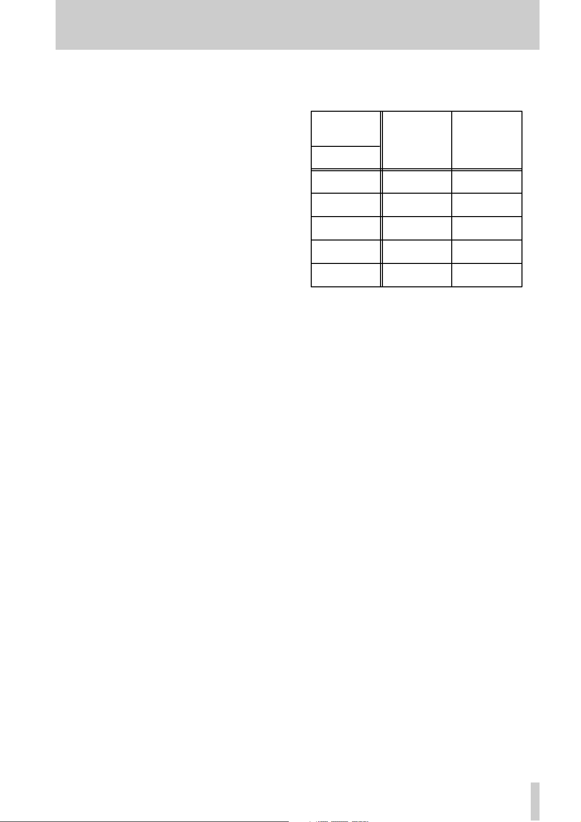
4 - Menu inter face, etc.
4.3.5 “Le f t ” and “ right” keys
W hen editing time values, etc. it is useful to be able
to edit one particular element (i.e. hours, minutes,
s e conds or frames) of the time value.
The “cursor ” is indicated b y a flashing d ot follo wing
the “field” currently being edited.
There are no dedicated left and right cursor keys.
Instead, when th e unit is in men u mode, press ing and
hold ing the
SHIFT
key and pres sing the ▲ key will
have the effect of a left cursor key.
SHIFT
L ikew ise, pr essi ng a nd holdi ng the
key an d
pres sing the ▼ ke y will have the effec t of a right c ursor key.
It sh ould be noted that there is an “invisible ” field to
the right o f the frames field . This allows th e who le o f
the displayed value to be increm ented, not just the
highlighted field. In other words, frame values, etc.
will “roll over” and increment the next field to the
left. In this mode , there is no flashing dot to indicate
the cursor.
R epeate d press es of these keys will a llow the edit ing
of the following fields (in order):
Hours ⇔ Minutes ⇔ Secon ds ⇔ Frames ⇔ Frames
(with in crem ent o f whole time value ) ⇔ Sub-frames
percentage ⇔ Sub-fram es perce nt age (w ith inc r ement of wh ole time value) ⇔ Sub-frames sampl e s ⇔
Sub - frames samples (with increment of whole time
value) ⇔ Hours , etc.
T he ri ght “cursor key” (
through th e list, and the right “cursor” key (
SHIFT
+ ▼) moves forward
SHIFT
+
▲) moves backward.
The sub-fra me dis plays (in italics abov e) a re
explained in the section below (4.3 .6, “Sub-frame
values”).
4.3.6 Sub- f rame values
There are two ways of r epresenting sub-fram e values: as “percentage” subframes, or as s amples.
When sub-frames are displayed as percentages, the
mini mum di sp l ayed va lu e i s al w ays 00 and t he max-
imum displa yed value is 99.
When displayed as a sample value, the n umber o f
samp les per frame varies, according to both the samplin g rate, and the frame rate currently selected:
Sampling
frequency
24
25
29.97
30
AB S
→→→→
↓↓↓↓
48 kHz 44.1 kHzFrame rate
1999 1469
1919 1763
1601 1471
1599 1469
1439 1322
When moving around a time value in the way
described above, moving the “cursor” past the frames
field will c hange the d isplay to a sub-frame display.
A s ub-f ram e display shows SF (
SF
), followed by
either the 2-digit rep resenta tion of the percentage
subframe value
SF ;;
of the sample value
, or the 4-digit representation
SF ;;;;
.
There are four modes of sub-frame display:
• Percentage
• Percentage with increment of whole time value
• Samples
• Samples with increment of whole time value
I n the two d ispl ay modes where ther e i s an incremen t
of the whole time value , there is no dot displayed.
T hese modes are acce ssed , as expla ined above ( 4.3.5 ,
““Lef t” and “right” keys”) using the “cursor keys”.
To retur n to the hh :mm:s s.ff d isplay , m ove the cursor
“outside the display”, i.e. to the right of the subfr ame field when the “samples with increment of
whole time value” mode is display ed.
4 .3.7 Usi ng the DA T A/LEVEL kno b to set
valu es
In some menus and other parameter settings, it is
possible to use the
cal values.
DATA/LEVEL
knob to set numeri-
1
Press and ho ld down the
SHUTTLE/DATA
the
key.
SHIFT
key, and pre ss
This data setting is the defa ult setting, made at
power-up.
2
When ed iting the valu e of a par amete r , and the
SHUTTLE/D ATA
indicator is blinking slowly,
TA SCAM DA-78HR
22
Page 23
4 - Menu interface, et c.
the current position of the knob and the current param eter val ue do not match.
3
Whe n the
SHUTTLE/D AT A
indicator knob
blinks rapidly, the cu rrent position of the knob
m atches the curren t para meter value. Turning
the knob from this position will now allow the
p aram eter val ue t o be changed.
4
Turn off th e “data en tr y” mode us ing the
SHIFT
SHUTTLE/DATA
and
ke y com b i n at i on .
Un til the match described above has been made, the
val ue of the p ara meter can no t be changed using the
kn ob.
Disp lay shows
as the curr ent value
In dicator
flashes slowly
Current position
cor respon ds to
D isplay now shows
as the current value
Indicator
f l ashes fast as
soon a s dial is
turne d past
po s it i o n
102
102
23
110
This position
corresponds
102
to
This position
corresponds
to
102
Current posit i on
corresponds to
110
Note th at because of the p recisio n of the knob, the
value may sometimes appear to “jump”.
Fi ne - tu ni n g of v al ues sh ould be done w it h t he ▲ and
▼ ke ys.
Display
PK. HLD
(peak hold)
Met er peak hold time
RLs.
(re lease tim e)
Met er release tim e
save.
(save)
Saves the cur rent settings to the tap e
Load.
(load)
Loads se ttings from tape
V alues
(*=d efault)
0, 1
through 9
seconds (default
3
CNT
is
),
(contin-
uous)
FAST
SLOW
*,
MED
(slow ),
(medium)
OFF
OFF
* 7 . 14, “Sav ing set-
*
Describ ed in
7.8. 1, “Pea k hold
time”
7.8. 2, “Meter ballis ti cs”
t ings to tap e”
7.15, “Restoring
settings fr om tape”
4.5 AUDIO1 menu
AUDIO. 1. --
are used to contro l the aud io operati on of the unit
usin g th e first a udio menu:
Display
D. IN.
The following parameters
V alu es
(*=d efault)
TDIF
SPD
(SPDIF)
(TDIF)*,
5.3. 1, “Digi ta l input
sele ction ”
Describ ed in
4.4 SYSTEM menu
SYSTEM--
used to con trol an d provide inform ation regarding the
ov eral l ope rat i o n of the un it:
Display
iD. sel.
(ID selection)
ID w hen the unit is connec t ed in a c hain of DT RS un it s
time. mode.
(time mode)
Reference t iming source
CLOK. MODE
(clo ck mode)
Clock source fo r a slave unit.
The following parameters are
V alues
(*=d efault)
1
* through
ABS
TC
*,
AUTO
INDViD
*,
(individual)
15
Described in
8 . 2. 2, “S et t ing
machine ID”
9.1, “ABS and
timecode”
8.6, “Individual
clo ck mo de”
Selects digita l audio source (for tracks 7 and 8 only)
IN. PATCH
(input patch)
Track input source can be eit her analog, digital or a recorded
track
TDIF.
(TDIF)
Input digital word length
DITH
(dit her)
Dit her nois e s hap e
ALL. ANALG
analog),
DGTL
in dividu al t rack s
set to
lo g),
T;
or
24
*, 20,
OFF
angular),
angular)
* (all
ALL.
(a ll digita l),
A;
(a na-
D;
(d igital)
(track)
16
RECT
*,
(rect-
TRI
(tri-
5.3, “Inp ut selection”
5.4. 2, “S elect ing
input word length”
7.11.1, “Select ing
dither se ttings ”
23
TASCAM DA-78HR
Page 24
4 - Menu inter face, etc.
Display
REC. MUTE.
(rec mute)
V alues
(*=d efault)
ALL OFF.
ON
or individual
ON
tracks
or
*,
ALL
OFF
Rec mute fun ction
4.6 AUDIO2 menu
Audio. 2. --
tional audio p a rame te r settings:
Display
C. FADE.
(crossfade)
Crossf ade tim e for p unch, et c .
Out. Patch
(output patching)
Output patchbay
out. bit.
(ou t put word
len gt h)
(word length of digital output)
ShTL. MoN.
(shu ttl e monitor)
Shuttle m onitor function
ShTL. MuT.
(shu ttl e mute)
Shuttle m ute function
OSC.
(oscillator)
Line-up oscillator
T his menu provide s add i-
V alu es
(*=d efault)
10
* through
( in 10 ms increment s)
Normal*
mal or as s et )
16, 24
0
(off)*, 1 (on ) 6.3, “Shuttle m oni-
0
(off)*, 1 (on ) 6.4, “ S huttl e mut-
OFF
*,
(1k)
200
(nor-
* 7.12 .1, “O utput
440, 1k
Describ ed in
7.10, “REC MU T E
(re c ording s ilenc e)”
Describ ed in
7.5, “Cr os s f ade
times”
7.12.2, “Out put
patchbay”
word le ngth ”
tor”
ing”
7.9, “Sine oscillator”
4.7 TC menu
TC --
control timecode operatio ns:
Display
TAPE. TC
(tape TC)
Tap e time code source
FRm mode
(frame mode)
System frame mode and external/tape frame rate display
DISP.
(TC display)
Timecode display source
In. TC. TMG
( input TC t im ing)
Incoming timecode refe rence
OUT. TC. TMG
(output TC timing)
Outgoing timecode reference
OUT. TC. SRC
(output TC
source)
S ource of outgoing timeco de
The fo llowin g parameter s are us ed to
V alu es
(*=d efault)
TC TRK
* (TC
CONV
track),
(converted),
(absolute)
SYS*
(EXTERNAL),
TAPE
29DF
29ND, 25, 24
30DF
TAPE
EXT
diff
ANALOG
DIGITAL
ANALOG
log),
(digital)
TAPE tc
tape),
(regenerated),
RESHAPE
(reshaped)
ABS
(SYS),
(T APE):
30ND
*,
* (off -t ape ),
(external),
(di fferenc e)
*,
* (ana-
DIGITAL
* (f rom
REGEN
EXT
,
,
Describ ed in
9.2, “Tape timecode mode”
9 . 3, “Selec t ing th e
frame mode”,
9 . 4. 1, “Show ing
input timecode”,
9 . 5. 8, “C hec k ing
the fra m e mod e of
st riped t im ecode”
9 . 4. 1, “Show ing
input timecode”
9 . 4. 2, “T imecode
input timing”
9 . 4. 6, “T imecode
output timin g”
9 . 4. 3, “T imecode
output”
FAST lTC
(fast LTC)
Fast LTC output mode
5 FRm
* (5
frames),
(l ea p),
LEAP
OFF
TA SCAM DA-78HR
9 . 4. 5, “Fast linear
timecode (LTC)
output”
24
Page 25

4 - Menu interface, et c.
4.8 TC chase menu
TC. CHS --
used to control th e DA-78HR operations when ch asing to an incom ing timecode signal:
Display
INDiv. REC
(individual recording)
En abling i ndividua l rec ord ing whi le c hasing
RECHS. MD
(re c hase mode)
Rec hase m ode
RECHS. WD
(re c hase window )
Width of recha s e “wind ow”
ERR. BYPAS
(e rror byp ass )
The following parameters are
V alues
(*=d efault)
0
* (off) , 1 (o n) 9. 6.11, “Individ ual
RECHASE
(rechase),
(free)
1 SEC
or 2 seconds)
10 FRM
(10 or 30 frames)
2 SEC
*,
*,
*
FREE
30 FRM
Described in
re c ording w hile
chasing timecode”
9 . 6. 9, “Rec hasing
timecode”
(1
9 . 6. 9, “Rec hasing
timecode”
9.6.10, “Bypassing
tim ecod e errors ”
Display
TC. REC. EN
V alues
(*=d efault)
0
* (off ), 1 (o n) 9.5. 2, “R ec ording
(TC recor ding
en able)
En abling of t im e c ode rec ording
STRT. Time
(TC generator)
Time value in
hh:mm :ss.ff
(00:00:00.00*)
Start t im e for o n-boa rd generato r
TCG. MODE
(TC generator
mode)
reset
CoNT
* (reset) ,
(continue)
Res t art m ode f or on-board generator
TCG
.
(TC generator)
stop
run
* (stop ),
(run)
Start/stop timeco de generato r
4.10MIDI menu
Describ ed in
tim ec ode us ing the
ge nerato r”
9.5. 2, “Recording
tim ec ode us ing the
ge nerato r”
9.5.3, “Generator
modes”
9.5. 2, “Recording
tim ec ode us ing the
ge nerato r”
Le ngth of t im e for e rror b y pass when c hasing
PK. POS . TST
(park p osition
OFF
ON
*,
9 . 6. 6, “Pa rk pos itio n”
test)
P erforms the park position test
PARK. POS.
(park p osition)
00 00
* (0 se c-
onds, 0 frames) to
01 29
(1 second,
9.6. 7, “Automatic
pa rk position set-
ting ”
29 frames)
Park position timing
4.9 TC generator me nu
TCG. REC--
used to contro l the internal timecode gene rato r.
Display
TC. REC. SRC
(TC recor ding
source)
Selects the source of th e time code “stripe”
The following parameters are
V alu es
(*=d efault)
EXT
* (external),
TCG
( T C genera-
TAPE TC
tor),
(tape timecode)
Described in
9 . 5. 1, “S elec ting
the timecode
source ”
MIDI--
The following p arameters are used
to c on trol the MIDI parameters of the DA-78HR.
Display
MIDI
(MIDI)
Enables or disables MIDI (including MTC)
ID
(MIDI ID )
MMC ID
MTC
(MTC)
MTC output
FAST. MTC
(fas t M T C )
MTC output in fast wind mode
STOP. MTC
(stop MTC)
MTC output in st op mode
V alu es
(*=d efault)
on
off
*,
ALL
*, 1 to 1
ON
OFF
*,
on
off
*,
on
off
*,
27
Describ ed in
10 .1 , “MMC enable
an d disab le”
10 .1 . 1, “As s ignin g
a MIDI ID to the
DA-78HR ”
9.4.4, “MTC output”
9.4.4, “MTC output”
9.4.4, “MTC output”
25
TASCAM DA-78HR
Page 26

4 - Menu inter face, etc.
4.11M aint ena nce men u
MAINTN--
informa tion relating to main te nance procedures, etc.
Display
version
(version)
System , front panel driver, servo software (f irmware) versions
DRUM. TIM
(dr um time )
Numbe r of hour s th e drum h as been in use
CLEN.
(cleaning)
Starts the head cleaning process
B. E. R.
(b loc k error rate)
Displ ays the current b lock error r ate
init.
(ba cku p memo ry
initialization)
The following menu provides
V alu es
(*=d efault)
SYS
(system).*
Frnt
(servo)
TOTL
SRCH
OFF
* 1 1.1, “He ad and
OFF
*,
off
* 1 1.2, “Bac k up
(front),
* (total),
(searc h)
ON
Svo
Describ ed in
11. 3, “Checking
version numb ers”
11.1 .3, “Ch ecking
dru m time”
transpor t c leani ng”
11.1 .2, “Ch ecking
e rror ra t es ”
memory initial iz ation”
4.12Dedicated keys
The follo wing (shif ted) k eys also allo w settin gs to be
made. These are fully described in the appropr iate
sections of the manual:
Ke y D escription Describ ed in
DELAY
OFFSET
PREROLL
PITCH
LOC/MEMO 1
LOC/MEMO 2
Individual relative
track delay
Offset r ela tive to
timecode or abso-
lute times
Locate pre-roll
an d aut o-p unch
pr e- and post -r oll
times
Varispeed
(±6.0%)
Lo c at ion me m ory
po int s
7.3, “Tr ack delay”
8.3, “Machine off set” an d 9.6 . 2,
“Timecode of fset ”
5 . 6. 4, “Editi ng t he
pre-roll and postroll times” and
7.1.3, “S ettin g the
location pre-roll
time”
7.6, “Vari speed
(pitch control) ”
7.1, “Autolocation”
DEVTYPE
(emulated device
type)
DA-78HR
da-38, da-
88
,
98
*,
da-
7.13, “Emulation”
TA SCAM DA-78HR
26
Page 27

5 - Basic operat io ns
This section explains some of the basic operation s
using the DA-78HR. Section 7, “Advanced operations ” describ es mo re advan ced operatio ns.
Most operations on a DA-78 HR are similar to th ose
on a tr aditio nal analo g multitrack recorde r, but we
s uggest th at you read this section and the next to
learn about th e features of the DA-78HR.
5.1 Formatting a tape
Before you use a tape in the DA-78HR, you must
fir st format it. This marks internal synchron iza tion
p attern s for the serv o to follo w on su bsequent passes
through th e tape as well as the subcode data (ABS).
Th e process also initializes the tape for recording at
eith er 16-bit o r 24-bit resolution.
No audio data is normally recor ded during a formatting o per ation (but see below).
5.1.1 Sel ect ing a w ord cl ock sou rce
1
Use the
NOTE
Remember that in your digital audio setup, only one
digital audio device should be set to be a clock master. All other digital audio devices must derive their
cl ocks from it.
There are four optio ns available:
• WORD (the
word clock received at the
nector. You may u se this setting wh en reco rding
digital audio throug h the TDIF-1 input, if the
source of the audio is set to be a clock m aster.
• I NT (i nternal)—both the
CLOCK
other digital audio devices are to be word clock
slaves, or if the in put signals are analog.
• DIG ITAL IN— thi s re f ers t o th e SPD I F (
input . Use this if the r e c ording source is to be
received here, and the source device is a word
clo ck mas ter .
• SYNC IN—this cannot be set using the
key, but occurs automa tically when the DA-78HR
is being controlled from another DTRS unit, and
the
made (see 8.1, “Synchronization connections”).
Neither the
light at this time.
CLOCK
key t o select a clock source.
WORD
indicator lights)—th is is the
WORD S YNC IN
WORD
and
DIGITAL IN
indicators light. You m a y use this settin g if
COAXIAL
CLOCK
REMOTE IN/SYNC IN
WORD
nor
connectio n ha s been
DIGITAL IN
indicators will
con-
5.1.2 Formatting
While f ormatting is proceeding, you cannot perf orm
any other transport oper ation except stopping the
tape.
Yo u cannot change the sampling ra te or the bit resolution wh ile fo rmattin g is in progress.
1
Swit ch on the DA-78HR and load a tape into
the tape loading slot. As the tape is loaded and
t hread ed, the tape counter sho ws
“
--LOAD--”.
For de tails of tape s that you can use in the DA78HR, see 1.5, “Recomm ended tape s ”.
2
3
4
NOTE
If you do press the
then change your mind about formatting the tape,
use either the
operation.
5
)
NOTE
If a digital signal is received at the
or at the SPDIF (
recording and playback sampling frequency is automaticall y determined by the sampling frequency of
the i nput signal and you cannot change it.
6
REW
Press
to ta ke the tape to th e beg in n ing
and s top the t ap e.
Pr ess the
FORMAT (
Pr ess the
FORMA T/Fs
FORMAT
FORMA T/Fs
onds. The display will then sho w a flashing
followed by all dashe s (
If yo u do not press the
within 5 sec onds the
key. The di sp lay sho w s
).
key ag ai n wi thi n 5 s ec-
F- -- -- --).
FORMA T/Fs
FORMAT message will dis-
key twice
F,
appear. This is a feature designed to s top you
formatti ng a tape a ccident ally.
FORMAT/Fs
CLEAR
or
key twice and you
STOP
key to cancel the
Select the sampli ng frequency (eit her 44.1k Hz
or 48k Hz), using the
FORMAT/Fs
key.
The sampl ing frequenc y that you sele ct
depends on t he eventu al use for t he recording.
For audio work, select ing 44.1kHz w ill allow
you to produce C D mas ter tapes with no frequency convers i on.
DIGITAL I/O
COAXIAL
) inpu t, the DA-78 HR’s
Select the recording mode using the
ja ck
HR MODE
key. W he n HR mod e (24-bit recording) is
selected, the
HR
indicator to the left of the time
counter will light.
Remember that if HR mode is select ed, the
tape must be repla yed on an HR DTRS
TASCAM DA-78HR
27
Page 28

5 - Basic operati ons
record er . Of cou rse, a no n-H R (1 6- bi t ) r ecor ding made o n the DA-78HR can b e replayed on
any DTR S record er .
7
To start for matting the tape, hold down the
RECORD
NOTE
The ta pe counter may show a n egative A BS time for
a shor t while at the start of the formatting process.
While it is displaying a negative value, no audio
recording can take place.
8
T he tape will format to the e nd, and then
key and press the
rewind automatically.
You are now able to u se t he tape fo r recording.
All transport con trols are disabled during for matting,
except for the
STOP
key, which can be us ed to abort
the for mat proces s.
I t is possible t o for mat t apes on a number of DTRS
units simultaneously. For details, see 8. 5, “ Synchroniz ed formattin g”.
5.1.3 Abo rt in g the fo rmat pr oces s
To abort the process befor e formatting actually takes
place (i.e. you have pressed the
twice in error) , press the
CLEAR
The only transport operation you can perform once
form a tting has starte d is to st op the ta pe.
However, we do not re c ommend interrupting the forma tting process, but suggest that you let the tape run
to the end.
If you interrupt the formatting (or the formatting is
interrupted by a pow er cut or e ven ts beyond your
control), rewind the tape and start the format from
the beginning of the tape again .
5.1.4 Recording while formatting
If you have armed any tracks (you have press ed its
REC FUNCTI ON
ing), any audio signal routed to that trac k will be
rec orded while formatting is in progress.
NOTE
S
If y ou have recorded and formatted part of a tape, and you
wish to cont inue formatting and rec ording on t he rest of the
tape (“assembly ”), you should rewind t o a pre-formatted,
blank sec tion of the t ape and resum e f ormatting and
recording from there.
Recording and for matting will continue at the sam pling frequency used on t he f i rst part of the tape.
A v oid re -s t artin g re c or di ng and form at t in g fro m an
unfor matted section of the tape.
switch , and the in dicator is flash-
PLAY
key.
FORMAT/Fs
STOP
or the
switch
key.
5.2 Recording the first tr acks
There are a number o f differ ent way s of recordi ng t he
fir st tracks. Howe ver, all follow the sam e basic
principles.
• When usi ng a n ew l y-forma tte d t ape, we suggest
that y ou record a blank “leader” about 30 seco nds
long , starting from the beginning of the tape, to
avo id d ro pout. Leave a similar recorded b lan k
“trailer” at th e end of the recor ding. You can use
the Rec Mute fun cti on as a conve ni ent w ay o f
recording silence. See 7.10, “REC MUTE (recording silence)”.
• If the tape cou nter shows a n egative value, you cannot record on the tape at that pos ition.
5.2.1 Preparing to record
1
If you have not a lready loaded a formatted
blank tape, do so now.
2
Make sure th at varispeed is turned of f. Check
VARI SPEED
the
(pitch control)”.
3
Select the recording source (see 5.3, “Input
selection”) as either all digital, all analog or a
mixture of these sources. The DA-7 8HR conta ins a “patch bay ” which allo ws you to route
inputs to tra c ks.
5.2.2 Sel ect ing a cloc k source
1
If y ou ha ve select ed a digital s ou rce, you s hould
select the wo rd clock master using the
key.
This can either be an external wo rd clock connected to the rear panel BNC
necto r, or it ca n be the SPDIF (
digital audio signal. The appro priat e indicat or
to the right of the time counter will light.
Alternatively, if both of these are lit, the unit
will serve as th e word clock mast er in t he audio
syst em.
NOTE
Remember that there must be one, and only one,
w ord clock master unit in a d ig ital audio system.
5.2.3 Write-protecti ng cassettes
Yo u cannot record on a cassette where the write-prot ect tab has been closed (write-protected).
indicator 7.6, “Vari speed
CLOCK
WORD IN
COAXIAL
con-
)
28
TASCAM DA-78HR
Page 29

Hi8 cassette write tabs work in the opposite manner
to DAT cassettes , and “closed” m eans “writeprotect”.
If the tape is write-prote cted, eject the tape, open the
write-protect tab, replace th e cassette, and try again.
• Sony Hi8 cassettes (and those from some other
manufacturers) have th e words “SAVE” (write-pro tected ) and “R EC” (wr ite -enabled ) mold ed into the
cassette she ll by the protection ta b.
5.2.4 Reco rding the first tracks (i)
1
Arm the tracks on which you wish to record.
Press the
the indicator will start flashing.
2
Adjust the input signal levels so that the track
meters read high, but the
not light.
3
Hold d o wn the
PLAY
re c ording will star t.
The
tracks will light steadily.
REC FUNCTION
RECO RD
key of these track s;
OVER
segment d o es
key, and press t he
key. The tape will start moving and
REC FUNCT ION
in dic ators of all arme d
5 - Basic operat io ns
4
Stop recording as described above.
5 .2.6 Replaying the first tracks
When you ha ve positio ned the tape at the beginning
o f t he r e c ordin g yo u have ju st made (or at th e pr e -ro l l
point), you can start playing back the tape.
1
T urn off the
track you have just recorded ( no t compulsory,
but recommended, as this will preve nt you
from accide ntally hit ting the
going into record mode, overwriting what you
have already recorded).
2
Rewind the t ape t o the point that yo u star ted
reco rding and press
5.3 Input s election
This s ection descr ibes ho w to cho ose all analog or all
digital input sources when recording with the DA78HR. For othe r routing pro cedures , se e bel ow
(5 .3.2, “Input patchbay routing ”).
1
Pr ess the
mod e (
RECORD FUNC TION
PLAY
SHIFT
key so that the unit is in shift
SHIFT
indicator is f lashing).
RECORD
.
switch of the
key and
When y ou start recording, the po int at which
rec ordin g s tarts i s automatically stored i n to
memory for punch-in pur poses.
4
To stop recording and stop the tape, press the
STOP
key. You can also press the
PLAY
key,
which will continue t he ta pe movement, but
stop recording.
5.2.5 Rec ordin g th e basic t racks ( ii )
Th is is an alternative method of recording basic
tracks o n a blank, formatted tape.
1
Arm the tracks and adjust the levels as
describe d in [1 ] and [2] above (5.2.4, “Rec ordin g th e fi rs t tra c ks (i)” ).
REC FUNCT ION
The
tracks will flash.
2
Press the
3
When y ou rea ch the point at wh ich y ou want t o
PLAY
sta rt recordi ng, press the
REC FUNCT ION
The
tracks will light steadily.
The point a t which rec ording starts is automat ically stored into memory for punch-i n
purposes .
in dic ators of all arme d
key. The tape wi ll start mo ving .
RECORD
key.
in dic ators of all arme d
2
Pr ess the
AUDIO. 1-- (
3
Pr ess the
briefly shows
MENU
key until th e dis play shows
AUDIO1--
SUB MENU
IN. PAT CH (
).
key until the display
IN PATCH
) and then
chang es to the current set ting.
4
To change between all analog and all digital
inputs, pres s the ▲ and ▼ keys (
ALL ANALG
(
DGTL
– all digital).
– all an al og) or ALL DGTL (
ALL ANALG
ALL
In the above two settings, the inp uts are
map ped to the tracks o n a on e- to-on e ba sis (i.e.
input 1 is ro ut ed t o track 1, input 5 is routed to
tr ack 5, et c.).
5.3.1 Digital input sele ction
If 7 and 8 are selected for digital input, the D IN (
IN)
menu item allows you to choose between the
TDIF-1
If the SPDIF (
nals (
input a n d t he SP DIF (
COAXIAL
D7 an d D8) can t hen be route d to any track (see
COAXIAL
) input.
) inp ut is sele cted, these sig -
below, 5.3.2, “ Input patchba y routi ng” ).
NOTE
If the SPDIF (
poss ible to us e the other six ch annels of the
digital input. It is, however, possible to re cord analog
COAXIAL
) inpu t is selected, it is no t
D
TDIF-1
TA SCAM DA-78HR
29
Page 30

5 - Basic operati ons
signals or to perform track-bounce operations with
the SPDIF (
COAXIAL
) input selected.
No te that whatever digital source is selected, the
appropr iate clock must be selec t ed. If you are record ing fro m (say) a CD player, which typically cannot
accept a word clock, as well as fro m a TDIF-1 source
(e. g. a TASCAM dig ital mixer) the DA-78H R m us t
be set to ac cept the clock fr om the
DIGITAL IN
(see
5.2.2, “Selecting a clock source”) . This clock mu st
the n be sent fr om the
THRU
of the DA- 78H R to the
IN of the TDIF-1 device, which m ust be s et as a
wo rd sy nc sl ave.
1
Press the
is fla shing, and press the
display shows
2
Press the
shows
SHIF T
SUB MENU
D. IN (
MENU
AU DIO1--
SHIF T
key until the
ke y so that the
AUDIO. 1-- (
key until the displa y
D IN
) f ollowed by the current
indi cator
).
setting.
3
Use th e ▲ a nd ▼ keys to change between
TDIF (
NOTE
S
You c annot use the SPDIF (
sub-mixer while accepting a signal f rom the SPDIF
COAXIAL
(
You must use a tap e formatted at the s ampl ing frequency of this input (i.e. you cannot use the SPDIF
COAXIAL
(
V ar i speed is al so not po s sib l e wh en r ec o rd in g us ing
this input.
TDIF
) and SPD (
) input.
) input to record a CD on a 48kHz tape.
SPDI F—COAXIAL
COAXIAL
) output f rom the
).
5.3 .2 In put pa tch bay rout ing
To route inp uts to tracks whose n umbers do not co rresp on d to those of the inputs, or to mix the types of
inpu t sour ce (digital, analog or off-tap e):
1
Follow steps 1 through 3 in 5.3, “ Input select io n” above,
2
Press the
whic h the input will be routed.
3
The dis pla y c hanges to show the t rack n um ber
of the destination track, together with the
source (e.g.
track 1 has been selected, and that analog
input 1 is the so urce.
4
Use th e ▲ a nd ▼ keys to change t he i nput
source from
8),
through
REC F UNCTI ON
TRK 1 A1 (
A1 through A8 (analog 1 thro ugh
D1 thro ugh D8 (digital 1 thr ough 8 ) and T1
T8 (t rack 1 t hrough 8).
key of th e track to
TRK1 A1
) shows that
5
To select ano ther de st inati on tr ack, pr e ss that
REC
track’s
FUNCTION
key and repeat the
proc ess.
NOTE
If your setting results in al l tracks being fed on a onet o-one basis fr om the same input sourc e (analog or
d igital), t he display will chan ge to show this, a f ew
sec onds aft er the pa tchbay operation t hat caus ed
this to be the ca se.
The meter s can be used to see t he
T 7/ 8
T 5/ 6
T 3/ 4
T 1/ 2
D7 / 8
D 5/6
D 3/4
D 1/2
A 7/8
A 5/6
A 3/4
A 1/2
patchbay assignment using the
meters, as shown here. Each
meter gives the status of its correspondingly-numbered track.
SHIFT
Press
FUNCTION
and one of the
keys (as descr ib ed in
REC
4. 1.1, “Peak meters”) to toggle
this meter mode off and on. The
de fault at power-on is for this
mode to be on.
B ec ause of the limitation s of the
number of meter segments avail-
able, each segment is used to represent two inp ut po ss ibilities . The top third is us ed to
s how track sources, the middle third is used for digital, a nd the lower third for analog sources.
Wi th a digit al reco rder such as the DA- 78 HR, track
crosstalk is almost negligible (better than 9 0dB at
1 kH z) . F or this reason, you do not ha ve to w orry s o
much about the con straint s of c hoosing physi cal
t rack lo cations as y ou do with analog record ings.
5.3.3 Track bouncing
If you need to copy a track to another tr ack at any
time in the recording p rocess, rem emb er that track
copying in the digi tal doma in will a dd no no ise or
disto rtion. A digital c opy is a “clone” of the original,
and no loss of quality i s incurred .
Th e DA-78HR a llows you to copy tracks digitally,
and you can use the inter n al su b-mixer (see 7.4,
“Sub-mixer”) to com bine all tracks (level and pan
can be set) to track s 7 and 8.
NOTE
Becaus e the DA-78HR also allows a track to be
re pla yed a nd r ecor ded on to itsel f , a ll eight t racks can
be mixed i nte rnal ly and merged into tracks 7 and 8.
The basic method fo r going about this is:
1
Exit shift mode and ent er the
MIXDOWN
mo de.
30
TASCAM DA-78HR
Page 31

2
Enter shift mode, and enter the sub-mixer
mode.
3
Make the level and pan sett ings for th e tracks
which are to be combi ne d, as desc r ibe d in 7.4,
“Sub-mix e r ”. Se e this sect i on for full det ails o f
ho w to operate the sub-mix er.
4
You can use the D A-78HR’s SPDIF (
TDIF-1
and analo g ou tputs to moni tor track s 7
COAXIAL
and 8. Only tracks 7 and 8 will be output f r om
TDIF-1
the
and analog outp uts, and the other
track outputs will be mut e d.
5 - Basic operat io ns
5 .4.1 S amplin g freque ncy and word
length
If you attempt to recor d digitally from a digital
sou r ce which has a different frequency from that previousl y record ed as the DA-78HR’s tape format, th e
Fs
indicat or c orr espond ing t o the t ape’s sampling
),
frequency will start to flash. This indicates a f requency mismatch .
Recording with differen t sampling frequ encies is not
recomm ended – problems wil l cer tainly occur on
replay of such a recor ding.
5
Arm tra cks 7 and 8.
6
Reco rd tracks 7 and 8.
5.3.4 Returning to ALL ANALOG setting
Afte r tracks have been set individually, it may be
ne ce ssar y to return the inputs to all analo g. It is then
easy to return to all digital (see 5.3, “Input selection”), but setting all inputs to “all trac k” would be a
so mewhat po intless settin g!
1
While the unit is in “pa tchba y” mode, as
described in 5.3.2, “Input patchbay routing ”,
pre ss and hold down one of the ▲ or ▼ keys,
and press the o t her of these keys.
The routing will change to all analog (
ANALOG).
ALL
5.4 More on digital recording
The DA-78HR is able to ac cept (and o utput) digital
signals at the
for mat.
The DA-78HR should be connected to oth er TDIF-1
equi pme nt us in g a PW-88D or PW-88DL conne ctor
cable.
NOTE
Only use a TASCAM digi tal cable w hen making digital audio connections to the DA-78HR. Other types of
cabl e may ca use damage to the syst em, and the
wa rranty will be voided if such damage is ca used by
use of the wrong cabl es .
The DA-78HR should be set to be either a word
clock master or a word clock slave when connected
to oth er digital equipme nt. Ther e can only be one
word cl ock m aster in a setup.
DIGITAL I/O
con nector in T D IF-1
If you attempt to recor d digitally from a digital
source with a word length (5.1, “Formatting a tape” )
different from that for which the tape has been f ormatted, errors will occur. A g ood rule is therefor e to
keep one wor d length and one s ampl ing f r equency
throughout a tape.
5.4.2 Selecting input word le ngth
When data is acce pted thr ough the
nector, the word length of the inco ming data mu st be
set. T his can be selected f rom between 16- bi t, 20-bit
or 24-bit. This is no t the same as the re solution
record ed on tape.
To set the word length:
1
Pr es s t he
SHIFT
key so that t he
is flashi ng, and pre ss the
displ ay shows
2
Pr ess the
shows
TDIF. ;; (
AUDIO. 1-- (
SUB MENU
TDIF xx
key until the display
re nt input word length).
3
Use the ▲ and ▼ keys to c hoose betwee n 24, 20
and 16 -bit word le ng ths.
We suggest that you experiment with the dither
settings (7.11, “Dither”) if you find you are
r ecording qua ntization n oise at low levels when
the input w ord length is set to 2 0 or 24 bits and
yo u are record ing at 16 -bit resolution. Though
you will lose a little in the signal-to-noise ra tio,
total harmonic distortion figures will be
improved.
NOTE
If you are dubbing t r acks fr om a D A-88, this value
must always be set to 16 bi ts.
DIGITAL I/O
SHIFT
MENU
AUDIO1 --
key until the
con-
indicator
).
, where xx is the cur-
5.5 Overdubbing
Overdub bing subsequ ent track s is carried out in a
very similar way to r e cordin g the first trac ks .
TA SCAM DA-78HR
31
Page 32

5 - Basic operati ons
If you are unsure about the differen ce between monitoring m ode s as implemented on the DA-78H R, now
is a good time to read 6, “Monitoring”.
Obv iously yo u will w ant to record while you listen to
the off- tape signals f rom previously- recorded tracks
and the input source on tr acks where recor d ing is taking place.
5.6 Punch-in and punch-out
There are a num ber of ways in which the DA- 78HR
ca n be us e d to pe rfor m reli abl e pu nch-in and punc houts automatic a lly. Punc h poin ts can be set and
edited to frame accuracy, either from a cue list or
“o n-the-fly” in real time.
The DA- 7 8HR provides a rehearsal mode which simulates the punching process, allowing the artists to
pe rfect the timing of the new mate r ia l.
The mechanics of punching on a digital recorder
appear to the operator to be the same as on an analog
recorder.
Crossfading, however, is an im portant and u seful
func tion on digital recorders, to ensure continuity
between original and punched m aterial. In the cas e of
the DA-78HR , this crossfade tim e is adjustable from
10 millisec onds to 200 milliseconds (7.5 , “Crossfade
times”).
AUTO MON
The
rehear sal a nd punch modes, the material prior to the
pun ch po i nt is monitored off tape. T he m onitor ing of
armed tr ack s changes to source while rehearsals and
pu nching a re c ar r ie d out a n d t hen chan ge s to off- t ape
ag ain after the punch-out poin t See 6, “Monitoring”f or details of monitoring modes, includin g the
AUTO MON
Pre-roll
poin t
P re- r o ll time Post-roll time
TAPE SOURCE TAPE
TAPE SOURCE TAPE
TAPE SOURCE TAPE
TAPE TAPE TAPE
mode is essential he re: in bo th
mode.
Punch-in
point
Rehe arsal learn
Rehe arsal
AUTO IN/OUT
Repl ay check
Punch-out
point
Post-roll
point
NOTE
Though it is possible to perform punch r ecording in
ALL INPUT m ode, the monitoring in this mode does
not make it easy to perfor m accurate punch operations. We suggest th at yo u turn this mode off when
performing punch-ins.
5.6.1 Automatic punch point s etting
Whenever recording takes place, the time when
recording begins is automatically stored as a p unchi n time, and th e time when recordi ng stops is stored
as a punch-out time.
This is no t usu ally the way in which y ou will want to
set the pu nch po ints, ho wever. There are sev eral alterna tive way s in which you can set these points, as
des c ri b ed be l o w :
5.6.2 Setti ng punch points “o n the fly”
This method d emands sharp reflexes (but you can
ed it the punch poi nts later as we show b e low).
NOTE
If an optional footsw itch has been atta ched to the
rear panel
can be used in the following steps instead of the
RECORD
to set the punch-in point, and again to set the punchout point).
1
Press the
light).
This is not strictly spea king necessary for setting the punch poi nt s, but the
necessary for punch o pe rat ions, so we suggest
you turn i t on here.
2
Use the
track(s) on which you will be recording.
3
Press the
The indicator will flash, showing that the DA-
78HR is in “rehearsa l learn” mode.
4
Rewin d the tape to before where the punch is
to occur.
5
Start playing the tape ( pres s
You wi ll m onitor the off-ta pe signals.
6
At the poi nt wh ere th e punch is to occu r, pres s
RECORD
The
FUNCTION
light steadily. M onitoring will change t o input
source record ing for these t racks.
REMOTE PUNCH IN/OUT
PLAY
and
AUT O MON
REC FUNCTION
RHSL
keys (i.e. press the switch once
key (t he indicator will
key(s ) to arm the
(rehearsal) key.
.
RECORD
key will flash, and the
indicator of any armed tracks wi ll
jack X, this
AUTO MON
PLAY
).
REC
is
32
TASCAM DA-78HR
Page 33

5 - Basic operat io ns
NOTE
If you do not w ant to change to source monitoring on
the punch track(s) between the punch points when
setting the poin ts, do not set th e
for these tracks.
At any tim e w h en the
REC FUNCT ION
RHSL
indica tor is lit or
on
flashing, this means that recording will not
actually be ca rried out, even if the
key and/or the
REC FUNCTI ON
RECORD
indic ators ar e
lit.
7
At the poi nt wh ere you want to punch out,
PLAY
pre ss
The
tracks will start flashing again. The
.
REC FUNCT ION
i n di c at or of an y arme d
RECORD
key will g o o ut. Monitoring of these tracks will
r e turn to off -t ap e s ta tu s .
8
After the post-roll period, the tape will retur n
to t he pre-roll point (the punch-in point minus
t he p re- ro ll of fset).
RHSL
The
indicator will now light steadily,
showing that the DA-78HR is in rehearsal
mode.
If you need to trim these punch points to s ub -fra me
accuracy, you can do so u sing the procedure
de scr ibed in 5.6.3, “Setting pu nch points using the
f ront pa nel” below.
NOTE
If you want to alter the pre-roll and post- roll times,
see 5.6.4, “Editing the pre-roll and post-roll times”.
The punch-in and pun c h-out poi nt s will rem ain th e
same while you change the pre- and p ost- rol l ti mes.
5.6.3 Setting punch points using the fr ont pa ne l
Se tting the punch -in point:
1
Press the
the indicator l ights flashes or l ights st eadily.
2
Press the
light).
3
Press the
indicator f lashing).
4
Press the
The display will briefly show
Point
the punch-in point.
5
Us e th e s h ifted ▲ and ▼ keys (
RIGHT)
RHSL
(rehears al) key twice so tha t
AUT O MON
SHIFT
LO C 1 (MEMO 1
key (t he indicator will
ke y to enter sh i ft mod e (
) key.
IN POINT (
SHIF T
In
), and will then show t he c urrent value of
LEFT
and
to select t he “field” (hours, minutes,
seconds, frame s or sub-frames) that y ou want
t o edit, an d us e t h e ▲ and ▼ keys to change the
value of the punch-in time. Se e 4.3.5, ““Lef t”
and “right” key s ” for detail s.
Setting the punch-out point:
1
I f yo u h ave not al read y p e rforme d s teps 1 a n d
2, as described f or setting the punc h- i n point,
do them now.
2
Pr ess the
SHIF T
key to enter shift mode (
SHIF T
indicat or flashing) .
3
Pr ess the
4
Use the shifted ▲ and ▼ ke ys (
RIGHT)
LOC 2 (MEMO 2
) ke y .
LEFT
and
to select the “field ” (hours, minutes,
seconds, frame s or sub-frames) that y ou want
t o edit, an d us e t h e ▲
and ▼ keys to change the
value of the punch-out ti me. See 4.3.5, ““Lef t ”
and “right” key s ” for detail s.
The value of the punch-in point can be reset to
00:00:00. 00 (this in clud es in “invisible” sub-
fr ame value) by pressing the ▲ an d ▼ ke ys to gether.
SHIFT
After setting the punch time s, pr ess
so that the
indicator i s no longer flashing.
Yo u can locate the tape to the punch-in point (minus
the pre-roll time ) by pressing
NOTE
The methods descri bed above can be used to “trim”
punch points which have been captured “on the fly”.
LOC 1
.
5.6.4 Editing the pre-roll and post-roll times
As a def ault (factory) setting, the DA-78HR will
position the tap e 5 sec onds before the p unch-in point,
however this has been set.
The defa ult post-roll time is 3 seconds. You can alter
both the se times using the following method:
1
Make sure the
unit is in shift mode).
2
Pr ess the
3
When the display shows
PR 0005 RH
(
shown in minutes and seconds (when the displ ay sh ows
refers to the location pre-roll t ime, which is
different).
4
Use the ▲ and ▼ keys to c h an g e t he va l u es (the
sh ifted ▲ and ▼ keys act as cur sor ke ys
between minut e s and seconds).
SHIFT
indicator is flashing (the
CLEAR (PRE ROL L
) ke y .
PR. 0005. rh
), the t ime of the punch pr e -roll is
PR 0000 LC (
P R 000 0 LC
), th is
TA SCAM DA-78HR
33
Page 34

5 - Basic operati ons
5
Press the
so that the display shows
CLEAR (PRE ROLL
PO 0003 (
) key once m ore
PO 0003
),
i.e. the post -roll time.
Sinc e ther e is little point in setting pre- and post-roll
times to frame accu racy, you can only set t hese values to second accuracy.
The minimum values you can set ar e 5 seconds (pr eroll) and 3 seconds (post-r oll) and the maximum
valu e is 59 minut es 59 secon ds for bot h.
An y punch operatio n from now will take your setting
for pre- roll and use it when locating the tape to the
pun ch-in point. For example, if your pre - roll time has
been set to 10 seconds (00:00:10.00), and t he punchin po int is at 00:06:03.12, the tape will locate to
00 : 05 : 53 .12 wh e n sta r t i ng reh ea rs a l or pu nc h -i n .
5.6.5 Rehe ars ing the punc h-in
After you have set the punch points, and you have
loc ate d the tape to the pre-roll point, as described
above, you can rehearse the punch process.
1
Press the
steadily.
This indica tes that yo u are now in rehearsa l
mode.
2
Press
the pre-roll point .
3
At the punch-in point, monitor ing will change
to so urce.
RHSL
key so that the indicator lights
PLAY
. The tape will start playing from
1
While the tape is running, press the
( there i s no need to press
STOP
LOC 1
first).
The tape will return to the punch- in point,
minus the value specified in the punc h-in o ffset
(5.6.4, “E diting the pr e -ro ll and post-roll
times”).
2
Pressing
PLAY
will then re-s tar t the rehearsal
or punch-in proce ss.
• Pressing the
LOC 2
key will locate the tape to the
punch-out pos ition minus the punch-in pre-roll
time .
• These functi ons are on ly operativ e when the
AUTO IN/OUT
or
When th ey are off , the
indicators are lit or flashing.
LOC 1
and
LOC 2
ke ys
act normally.
5.6.7 Recor ding the punch-in
1
Make sure the tape is at the pre-roll point , and
pres s the
The indicator will flash, showing that the DA78HR is in auto -punch mode.
2
Press
At the punch-in point, the
will light steadily, a s will th e
indicators of any armed tracks. Monitoring
will c hange from off-ta pe to sour ce and the
INPUT MONITOR
light.
AUTO IN/OUT
PLAY
. The tape will start playi ng.
key once.
RECORD
of any armed trac ks will
indicator
REC FUNCTI ON
key
RHSL
will
RECORD
Th e
FUNCTION
key will flash, and the
indicator of any armed tracks will
REC
light steadily. However, recording will not be
carried out.
4
At the punch-out po int, monitoring will change
back to off-t ape monito r ing.
T he tape will contin ue playing to the post-roll
point and then rewind to the pre-roll point.
5
Repeat the rehearsal process until you are satisfied with the performance.
5.6.6 Interrupting a rehearsal o r punch recording
Ve ry often while rehear sing a punch-in, you will not
want to run the ta pe all the way to the pun ch-ou t
point (an entry cue is missed, or a mistake is made
ear ly on in the take ) . In the se c ases, the following
procedure applies to both rehearsal and punch
record ing:
Reco r ding will now actually take place. Any
r ecor ded material whi ch wa s previ ously on the
armed tracks between the punch points will be
replaced by th e new reco rding.
3
At the punch-out point , the monito ri ng will go
back to off-tape (the
INPUT MONI TOR
indicators of armed tra cks will go out ), and when the
post-roll point is reached, the tape will rewind
to the pre-roll point.
4
AUTO IN/OUT
The
indicator will light steadily,
showing that the DA-78HR is now in replay
mode.
5.6.8 Replay ing the punched material
1
To replay the punch- i n, press the PLAY key.
Playback will start (the
cators of the armed tra c ks will co nt inue to
flash).
2
At the post-roll point, t he t ape will autom atically rewind to the pre-roll point.
REC F UNCTI ON
indi-
34
TASCAM DA-78HR
Page 35

3
If you want to r ecord the punch-in again, pr ess
AUTO IN/OUT
the
key so that the indicator
fla shes, and repeat the process describ ed
above.
4
If you are satisfie d with t he punc h-in, follow
the steps below, o therwise, press
re turn t o t he punc h- i n point, press the
IN/OUT
key so that the indicator flashes, and
LOC 1
to
AU TO
repeat the take.
5 - Basic operat io ns
5.6. 9 Ex it i ng punch -in mo de
1
Di sarm any armed tra c ks (pr es s th e
FUNCTION
switches so that the indicators go
out).
2
Pr ess the
This will exit the
CLEAR
key.
AU TO IN /OUT
mode.
The
LOC 1
and
LO C 2
keys will ret urn to their
usual functi ons, but the punch poi nt s are still
r eta ined in memory.
REC
(or rehearsal)
3
Pr ess the
AU TO MO N
key so that the indicator
goes ou t.
Normal monitoring modes will now be in o per-
at io n (see 6, “Monitor ing”).
TA SCAM DA-78HR
35
Page 36

6 - M onitoring
NOTE
We strongl y advise you to read this section – the
effective use of multitr ack monitoring i s one of the
keys to an e fficient recording session.
Like all multitr ack recorde rs , the DA-78HR has a
number of di fferent mo ni to ri ng modes, de pen ding on
the curren t monitor status, tr ansport status and
whether the tr ack is armed o r not.
When a DA-78HR track is in playback mode, the
monitoring is off-tape.
The con trols which affect mon itoring are:
•ALL INPUT
• AUTO MON
In ad dition, there are two men u items affecting the
monitoring:
• shuttle monito r
• shuttle mute
6.1 ALL INPUT
When th is is active, the signal from the DA- 78HR’s
outp uts will always be the appropriate input source
sig nal fo r all tr acks .
NOTE
ALL INPUT
tions described below. Any shuttle monitor ing while
ALL INPUT
Th e shuttle monitor mode has no effect when
MON
When th e
overrides any shuttle mon it oring sel ec is on will always be source mo nitoring .
is off.
AUT O MON
and sh uttle mo nitor ing are
AUTO
both on , the output from a ll armed tr acks w ill be the
source input.
AUTO MON
If
is on, b ut shuttle mo nitoring is o ff, all
armed tracks will monitor off-tape in shuttle mode.
Y ou c an also disable off- tape s huttle m onito ring with
the Shuttle Mute functio n (6.3, “Shu ttle monito r”)
.
Shuttle m on itoring is atte nua te d by 12 dB compared
with other monitoring modes. T his hel ps to avoid
da mag e to tweeters, etc. when shuttlin g fast.
6.3.1Enabling a nd disa bling shuttle monitoring
1
Press the
is flashing.
2
Press the
AUDIO. 2-- (
SHIFT
key so that the
MENU
key until the display shows
AUDIO2 - -
SHIFT
indicato r
).
When the
ALL INPUT
key is pressed, its indicator
will lig ht. Mon itoring for all tracks will be source
monitoring, rather than off-tape.
6.2 AUTO MON
Thi s mode is primarily used in punch operations.
When au to moni tor mode is entered (by pr essing t he
AUTO MON
key), the
AUTO MON
indicator lights .
This au tomatically changes the moni toring on armed
tracks fr om off- tape to source when recording or
rehears i ng a recordin g, a n d ba c k t o off- ta pe w hen the
pun ch-ou t point is reached.
6 .3 Shuttle mo nitor
In ad dition to these modes, there is one further setting, that affects monitor ing , but on ly in one special
case – s huttle m ode. Usually, when shuttling the tape,
you will want to m onito r of f-tape. Ho we ver, if a tra ck
is armed, you m ay wan t to listen to the source input
sig nal, rather than the off-tape record in g.
3
Press the
shows
SUB MENU
ShTL. MoN. ; (
key until the displa y
SHTL MON x
, where
x
can be 1 (on) or 0 (off).
4
Use the ▲ or ▼ key to change the valu e to
(shuttle monitoring ena ble d) o r
0
(shuttle
1
monito ri ng disa ble d).
6.4 Shuttle muting
It may be sometim es desirable to mute off-tape output when sh uttling . The sh uttle mute fu nction allo ws
you to do this:
1
Press the
is flashing.
2
Press the
AUDIO. 2-- (
3
Press the
shows
can be
4
Use the ▲ or ▼ key to change the valu e to
(shuttle mute enabled) or
disable d).
SHIFT
key so that the
MENU
key until the display shows
AUDIO2 - -
SUB MENU
ShTL. MuT. ; (
1
(on) or 0 (off).
SHIFT
indicato r
).
key until the displa y
SHTL MUT x
0
(shu tt le mute
, where x
1
36
TASCAM DA-78HR
Page 37

6 - M onitoring
6.5 S ummary of moni tor modes
The following table sh ows what will be mo nitored
from a track. This depends on th e
AL L INPUT ON
AUTO MON
OFF
A L L INP U T
OFF
AUTO MON
ON
ALL INPUT, AUTO
REC
FUNCTION
ON
OFF
ON
OFF
ON
OFF
PLAYRECORD
TAPE
MON
and the
REC F UNCTI ON
settings, and on the
tr ansp or t mo de cur ren tly en gag ed.
STOP , R EW ,
FFWD
INPUT
INPUT
MUTE
(shu ttle m on ito r)
OFF
ON
OFF
ON
SHUTTLE
TAP E
INPUT
TAP E
MUTE
37
TASCAM DA-78HR
Page 38

7 - Advanced operations
7.1 Autolocation
The DA- 7 8HR contains t wo location memories,
access ible throu gh t he
also a llow a “A
↔B repeat” facility, which allo ws
LO C 1
you to rehearse part of a mixdown, for ins tance.
These two location memory points are referred to as
“MEMO 1” and “MEMO 2”.
As with the punch recording points (5.6, “Punch-in
and p unch-out”), it is possible to set and ed it these
poin ts in a number of ways.
7.1.1 Setting MEMO 1 and MEMO 2 “o n
the fly”
T his ca n be done regardless of the current status of
t h e t a p e tran s port (playi ng, r e c ordin g, w in d i ng,
s topped, or shuttle).
1
Pre ss an d hold down the
MEMO 1
the
The curre nt tape posit ion (when the
was pressed) will be stored to the appropriate
location memory (MEMO 1 or MEMO 2).
or
MEMO 2
and
SHIFT
key.
LOC 2
keys . Th ese
key and press
MEMO
key
5
When t he location times have been set, press
the
SHIFT
key to turn th e
SHIFT
mode of f and
return t he count er to its normal display.
7.1.3 Sett ing the locati on pre-roll t im e
W hen you locate to a location memory, the tap e will
s top at the memor ized location point, minus a prede fined pre- roll time.
As shipped , the DA-78HR’s defau lt location pre - roll
time is 0 seconds. You c an edit this to a value
between 0 s econds ( t he tape will locate to th e exact
loc a tion po int) and 59 minutes, 59 seconds, in 1 second incremen ts.
NOTE
This pre-rol l time is independent of the punch pr e-roll
tim e. See 5.6.4, “Editing the pre-roll and post-roll
times”.
1
Set the u nit into shift mode (press the
key so that the
2
Press the
3
The display will show
LC
).
SHIFT
indicator is flashing) .
CLEAR (PREROLL
PR 0000. LC (
) ke y .
SHIFT
PR 0000
T he displa y will indicate that the location
m emory point h as been stored (
PRESET
(
)).
PRESET
7.1.2 Checking, ed iting and manually
entering MEMO 1 an d MEMO 2
The check ing, editing, and man ual entry of the
Memo 1 and Memo 2 location points are all essentially the same opera tion. Locatio n points can be
edited and entered to frame accuracy.
1
Press the
flas h es .
2
Press eit her the
de pending on which loca tion p oint is to be
accessed.
3
T he display briefly shows
and then the currently-s tored l ocatio n memory
is shown on the d ispl ay. The “cu rsor” (flashi ng
pe ri od ) i s at th e “h ou r s ” fi el d .
4
Use th e ▲ and ▼ k eys to s et th e “hou rs ” valu e,
and mov e the “cursor” wit h the
and ▼ keys.
For details rega rding the entry of t ime values,
inc luding sub-f rame entry , see 4.3, “Menus and
sub-menus ”.
SHIF T
ke y so that the
MEMO 1
SHIF T
MEMO 2
or
MEMO ; (
key,
MEMO x
SHIFT
indi cator
ed ▲
4
Use the ▲ and ▼ k eys to set the location preroll time in minute s and s e conds ( up to 59 minutes, 59 second s). The
SHIFT
ed ▲ and ▼ keys
can also be used to move the cursor between
the minutes and s e c onds “ fields” .
When a loca tion memory is used, the tape will
now locate to the location po int, minus the
value y ou ha ve just enter ed . For i ns tance, if the
locat i on poi n t i s at “00:12: 0 4.03” an d y ou h av e
set a location pre-roll time of 5 seconds, the
ta pe will locate to “00:11:59.03”.
This pr e-ro ll tim e is d ifferent to the p re-roll time used
for punch oper a tions as described in 5.6.4, “Ed iting
t he pre-roll and post-roll times”.
7.1.4 Moving to MEMO 1 a nd MEMO 2
),
When you have set the locatio n memories as
des c ri b ed a b ove, yo u s i mp ly ne ed to pre s s t h e
LOC 2
or
keys to move the tape to these lo cation
LOC 1
poi nts.
Th e tape will locate to the location memory minus
the loca tion pre-rol l time, as de s cribed ab ove.
7.1 .5 L oc ation an d playba ck
I f you press t he
PLAY
(the
wh en it reache s the location point.
PLAY
key while the tape is locati ng
key will flash), th e tape will start playing
38
TASCAM DA-78HR
Page 39

7 - Advanced operations
If yo u pr es s
PLAY
the
PLAY
twice while the tape is locating,
key will light steadily, th e tape will stop
an d playback will start immediately.
If yo u a re u s in g t he D A - 78HR with a remote c o ntrol
un i t, a n d yo u ha v e have pr ess e d t he
AUTO PLAY
key
on th e remote control unit, replay will start auto matically wh en the lo cati on poin t is reached.
7.2 Repeat function
You can repeat playback continuously between the
two location mem ory p oints (Memo 1 and Memo 2 ).
NOTE
When we talk about the “first” and the “second” locations here, we are referring to the earlier and later
locati on times. Memo 1 could be at a later time than
Memo 2, and hence we would refer to it in thi s section as the “second location point”.
The tap e will wind to a little before the first point (if
it is not there a lr e a dy) and s ta rt playing. The off-tape
monitoring will star t at the fir st memory location and
co ntinue until the second loc ation is reached. The
tap e will then stop playing, and rewin d to a little
be fore the firs t point and start playin g again.
7.2.1 To sta rt repeat p lay
1
When the two location points have been set,
press the
2
T he tape will locate to the first location point
and st art playi ng until the sec ond location
point, rewind to the firs t locati o n poi nt, a nd
pla y ag ain. This pro cess will be repeated.
While the tape positio n is be tween the t w o
loc ation points, the
lit ste adily. It will flash while the tape position
is outside the two location points .
3
Stop the r ep eat funct ion by press ing the
REPEAT
out ).
If the tape is playing, it will c ontinue pla ying
(past the second location point).
If the ta pe is rewinding to the first loca tion
poi nt when the
stop.
NOTE
S
The two locat ion point s must be at least 5 seconds apart
for the repeat fac ility to be operat ional—if you att empt a
repeat operation when they are c loser toget her than t his,
the display show s
REPEAT
key (the
REPEAT
Too NEAR
key.
REPEAT
REPEAT
indi cat or will be
in dicat or will go
key is pressed, it will
TOO NEAR
(
).
If y ou hav e only set one locat ion point , the repeat will be
between “00:00:00.00” and t he loc ation point.
Pre ssi ng any transport control whil e repeat play is in
p rogress will stop the repl ay, but will not cancel the
repeat mode. To restart the repeat playback, locate
to e ither loc at ion point, an d while the tape is wind ing,
PLAY
press
is before the second location point.
. Alternativ el y , pr ess
PLAY
while the tape
7.3 Track delay
The DA-78HR allows you to delay tr acks relativ e to
t he other tracks, either when r ecording or playing
back. You can use this function for post-production
“slip”, compensate f or d elays caus ed by external pro cessing eq uip men t, allow for propagation delay in
multi-microph one sessions or add special effec ts.
Th e track delay can be set from –200 samples to
+7 20 0 samples . A nega tive numbe r me an s t hat th e
trac k o n which the “delay” setting is made is
ad vanced in time relative to the other tracks. However , t his d oe s not mean that the DA-78HR inclu des a
t ime mach ine! Since the mo nitoring head is a “v irt ual” head, made of a composite of delayed off - tape
an d input source signals, the “ position” of the recordi ng head can be adjusted in both directions.
1
Make sure th at the unit is in shift mode (the
SHIFT
indicator is flashing).
2
Press the
3
The display can s how the delay in samples or
milliseconds in which the delay is counted.
Press and release the
order to change between these two units.
Millisecond delays are shown as 3-digit values,
and sample displays are shown as 4-digit values (always with lea ding zeroes).
4
Ty pically, all tracks will have their delay set
toget her ( as shown by the display). Use t he ▲
and ▼ keys t o change the value.
Yo u can also use the
t he d elay value (see 4 .3. 7, “Us ing the DATA/
LEVEL knob to set va lue s”).
5
Press a track’s
individu al trac k whose delay value can be
chang ed.
6
To change from e d iting individual track val ues
back to all tracks tog e ther, pre ss and hold the
DELAY
RHSL (DELAY
R EC FUNCT I ON
) key.
DELAY
DATA/LEVEL
key briefly in
key to select an
knob to set
key for more than one second.
39
TASCAM DA-78HR
Page 40

7 - Adva nced operat ions
7
Press and hold the
SHIFT
key f or more than
three seconds to exit the delay setting mode.
The meter s can also be used to
give a vi s ua l indication o f t he
track delay.
SHIFT
Press
REC FUNCTION
and one of the
keys (as
des cr i bed in 4. 1.1, “Peak
positiv e values
meters”) to toggle this meter
mode off and on . The default
0 (zero)
neg ative v alues
a t p ower-on is for this mode to
be on.
The track delay, expressed in
s e conds, is between –4 to +150 milliseconds. At a
typical sound propagation rate, the maximum value
corres po nd s t o abo ut 50 me t ers (abo ut 16 0 feet ) of
distance .
7.4 Sub -mixer
One importan t fea ture of the DA-78HR is the ability
to mi x in put s ou r ces an d of f - ta pe s i gn al s i nto a s t ereo
signal wh ich is r outed to tr acks 7 an d 8 and can be
output at the rear panel SP DI F (
well as through channe ls 7 and 8 of the
tal an d analo g outputs). As well as the tr a ck delay
available on the DA-78H R for the tape tra cks, this
internal mix er also featu res l e ve l an d pan con trols, s o
that a simple mix can be obtained.
T his mixed signal is output only w hen the
indicator is lit. Pr e ssing th e (unshifted)
ke y will toggle the indicator between on and off.
COAXIAL
TD IF-1
MIXDOWN
) output (as
digi-
MIXDOWN
1
With mixdown mo de enable d, press the
SHIFT
key so that the indicator is fl as hi ng.
2
Pr ess the
MIXDOWN (LEVEL/PAN
) key. This
enters the level/pan setting mode.
3
If the display does not sho w
L xxx
— master level) , continue to press the
LEVEL/PAN
key until this is shown.
Repeat ed presses of the
MST. L ;;; (
LEVEL/PAN
MST
key o r the
currently-selected channel (as explained
below) will cy cle through the fo llowing :
master level →
→ channel level →
→ →
→ channel pan →→→→
→ →
channel input selection
4
Use the data knob a nd/or the ▲ and ▼ keys to
chang e the level between
0 (–∞
∞ dB) and 127
∞ ∞
(0 dB).
The 7 and 8 meters may be used to sho w the
level (toggle with
0dB
segment represents a value o f 12 7, and
–12 dB
the
SHIFT+REC FUNCT ION
). T he
segment represents a v alue of 64.
7 .4.3 Leaving ed it/pan setti ng mod e
When th e un it is in edit/p an setting mode as ab ove, it
can be returned to normal operations (as s hown by a
change in the di splay) by either of the f ollowing
methods:
Entering another shift mode function (e.g.
delay)
or
SHIFT
Press ing the
key so that the
c a tor stops flashing (ex iting shif t mo de ).
SHIFT
indi-
A temporar y “patch ” can als o be set up for this submix, o verriding th e curr ent input patch settin gs while
the mixdown mode is active.
NOTE
MIXDOWN
When
through 6 (anal og and digital) are not output.
is on, the signals from channels 1
7.4.1 Entering mixdown mode
1
Make sure th e
2
Press the
cator will light.
Pr es sing the
off) will exit mixdown mode .
SHIFT
MIXDOWN
MIXDOWN
indicator is off.
key. The
MIXDOWN
indi-
key ag a in (with shift mode
7.4.2 Sett ing the m ast er level
Th is is the master level of all signals output through
channels 7 and 8 .
NOTE
Remember that turning off the edit/pan setting mode
will n ot automat ic ally turn off the mixdown mode. To
turn off the m ixdo wn mode, you must turn o ff th e shi ft
mode and then press the
MIXDOWN
key.
7 .4.4 Sett ing le vels and pan posi t ions
To set the individ ual channel levels and p an
positions:
1
Make sure that the unit is in level/pan setting
mod e, as described abov e (7.4.2, “Setting the
master level”).
2
Pr ess the
corresponds to the chan nel y ou want to set.
The
the meter will start to flas h, showing that t his is
the active channel being edited.
REC FUNCT ION
R EC FUNCT I O N
key who se numbe r
indi cator at th e bot tom of
TA SCAM DA-78HR
40
Page 41

7 - Advanced operations
T he displa y will show the level and pan position of the channel . For ex ample,
L. 02. P -C-
wo uld indi c ate a level of 102 and a center pan
position.
3
Use th e ▲ a nd ▼ keys and/o r the knob to
change the level of the active channel.
4
To change the level of another channel, press
that channel’s
REC FUNCTION
key.
The meters may be used to show t he value of
the c hann el levels (the default is for this function to b e on, and it may be togg le d wi th the
SHIFT+REC FUNCTION
5
Press the
FUNCTION
LEVEL/PAN
key of the currently active channel
com bination).
key or the
REC
to change the cursor (fla shing period) to the
pan setting.
--R
R62
-C-
L62
L--
Pan values range from
P.L --
(
hard left) through P. L62
(immedia tely to the right of the
hard le ft set tin g) ,
center) and
P. R62 (
almos t hard right) to
P.--R
(
—h ard right) .
The meters are also b e used to
sh ow the pa n settings. Press
SHIFT
and one of the
FUNCTION
keys (a s described in
P. L--
P. -C- (
P.R 62
P. --R
REC
P.-C -
—
—
4. 1.1, “Peak meters”) to tog gle this meter mode off
an d on. Th e de f a ult at po wer-on is for this mode to be
on.
6
Use th e ▲ a nd ▼ keys and/o r the knob to
adju st th e pa n setting s of the ac tiv e ch a n nel .
7.4.5 Setting the sub-mixer inpu t sources
wit h th e o utpu t of the corre spon di ng ly- nu mbered track.
NOTE
These as signments are temporary, and remain only
as long as the mixdown mode is enabled. When the
mixdown mode is disabled, the previous input patchbay settings are restored.
5
To record the mixer outputs onto tracks 7 and
8, arm these tracks a nd reco rd in the usual
way.
7.5 Crossfade times
As menti on ed e ar li e r (5.6, “ P un c h- i n a nd punch out”), digita l punch recordin g requires that the original and new s i gna l be cros sfa ded over a shor t period
of time.
The factory default crossfad e time for th e DA-78HR
is 10 ms, an d th is can be adjusted in 10 millisecond
steps t o a max imum of 200 m s .
For the most part, 10 m s is an ad eq uate value and
wi ll produc e seamle s s pu nches , but the r e m a y be
time s ( match ing reverb settings, e tc .) when a longer
crossfad e is required.
1
Press the
is flashing, and pre ss the
displ ay sho w s
2
Press the
shows
SHIFT
key so that the
AUDIO. 2-- (
SUB MENU
C. FADE;;; (
SHIFT
indicato r
MENU
key until the
AUDIO2 - -
).
key until the displa y
C FADE xxx
), where xxx
is the current crossfade time in millisec onds.
3
Use the ▲ and ▼ k eys to ad ju s t th e c rossfa de
time (10 throu gh 200 ms i n 1 0 ms steps)
7.6 Vari speed (pitch control)
1
From t he pan setting, as describe d i mme diately a bov e, press ei ther t he
key of the act ive c hannel, or t h e
REC FUNCTION
LEVEL/PAN
key.
2
T he displa y will show the c urrent inpu t s ource
for th e channel, e.g .
In 1 t1 (
In 1 t1
—the
input source for channel 1 is track 1).
3
Use th e ▲ a nd ▼ keys to cycle through
through
a8 (analog inputs 1 thr oug h 8) and d1
through
4
Pressing the ▲ and ▼ keys together will “nor -
t8 (t rack 1 t hrough 8), a1 through
d8 (digital input s 1 thr oug h 8).
m alize” the sub-mixer, feeding each channel
41
TASCAM DA-78HR
t1
The speed o f reco rding and playback (and hence the
pitch) of the DA-78HR can be adju sted to 6% above
or below normal s peed i n 0.1% steps.
NOTE
You cannot operate the pitch control when the DA78HR i s slaved to another unit, or synchronized to an
external word clock. If the clock is changed to external whi le varispeed is on, the
will go o ut. The indic ator will also go out if ch asing is
en abled while varisp eed is o n.
VARI SPEED
indicator
7.6.1 To set a non-standard spe ed
1
Press the
light, and the
VARI SPEED
SHIFT
indicator will flash.
key. Its indicator will
Page 42

7 - Adva nced operat ions
2
Use the ▲ and ▼ keys to change the value
(maximum +6.0%, minimum –6.0%, in 0.1%
steps).
Reset the value to 0.00% by pressing and holding either of the ▲ or ▼ keys, and pressing the
other.
3
Press the
mode. The
SHIFT
key to turn off the setting
V A RI SPEED
indica tor will continue
to be lit, showing tha t varispeed is currently
enabled.
4
Turn off varispeed (when the
indicator is lit ) by pres sing t he
VARI SPE ED
VARI SPE ED
key to turn the indicator off.
NOTE
VARI SPEED
The
varispeed i s enabl ed, even if the speed is set to
0.0%.
in dicator will light whenev er th e
Play back an d recor ding will now take p lace at the
new speed.
7.7 Shuttle operations
AUT O MON
Wh en
armed tracks will be off-tape, unle ss the
is on, the monitoring of any
SHTL MON
is on, in which case, t he monitoring of armed tr acks
will be source input. The monitoring of all other
(unar med) tr acks can still be s witched on a track -bytrack ba sis using the tracks’
I NP UT MONITOR
switches.
SHT L MON
The
MON
is on. W hen
key is only enabled when
AUTO MON
is off, it has no effect.
AUTO
7 .7.2 Shu ttl e muting
As expla ined above, shuttling the tape will usually
allow off-tape monitoring. However, there may be
times whe n you will wan t to mute all off- tape signals
when shuttling. This procedure is described in 6.4,
“Shuttle mu tin g”.
7.8 Meter mode s
Th e D A-78HR peak bargraph meter s ca n be customized to suit your working preferences. Both the peak
hold time and the “ ballistics” of the meters can be
adju sted.
Th e shuttle key, ind ic ator and knob are used to simulate the “rock and roll” location method on o pen -ree l
tap e decks , allowing you to locate a p oint on tape
through audible cues.
As the knob is moved f rom the cen ter detented po sition, the sh uttle speed becomes highe r.
Th e va r ia tion in speed is not continuous; but as you
turn the k no b from the center position, the shuttle
speed changes, follo wing these values (relative to
norma l speed): 0.25, 0.5, 1.0, 2. 0, 4 .0, 8.0. The 1.0
s peed is only ava ila ble wh en shuttlin g in the forwar d
direction.
Shuttle ope r a tion s are only possible when the
TLE
indicator is lit (pre ss the
SHUTTLE
If the
knob remains untouched at the
SHUTTLE
SHUT-
switch).
center
positio n for 10 seconds, the shuttle mode is disabled,
and the indicator goes off.
7.7.1 Shut t le moni t oring
Th is is also covered in 6.3, “Shuttle monito r ” . T he
de fault behavior of the DA-78HR is tha t when s huttling th e tape, you monitor off the re c orded ta pe.
NOTE
When monitoring in shuttle mode, the monitor signal
is attenuated by 12 dB (to avoid possible dam age to
ea r s an d sp eak er s ).
7.8.1 Peak hold time
1
Pr es s t he
is flashi ng, and pre ss the
displ ay shows
2
Pr ess the
shows
with the current value for this setting.
3
Use the ▲ and ▼ keys to change the value
between 0 and 9 seconds or
t in ue—whi ch wil l p ermanently di sp lay th e
maximum peak signal level. T his can be useful
if you are do i ng a “dry run” re he arsal, but you
canno t keep your ey es o n the meters all the
time that the rehearsal is going on).
To turn off the peak hold display if
been set, change the peak hold value t o
onds and the meter segments will “drop back” .
SHIFT
key so that t he
SYSTEM-- (
SUB MENU
PK. H. LD. ;; (
SHIFT
indicator
MENU
key until the
SYSTEM--
).
key until the display
PK HLD xx—
CNT
peak hold)
CNT
(
—con-
CNT
0 sec-
has
7.8.2 M e t er ball ist ics
Use a similar pro ces s to chan ge the “fal l- back” ballistics of the peak me ters. You can not change the rise
time of the meter s, which are fixed with peak meter
characteristics.
1
Pr es s t he
is flashi ng, and pre ss the
displ ay shows
SHIFT
key so that t he
SYSTEM-- (
SHIFT
MENU
SYSTEM--
indicator
key until the
).
TA SCAM DA-78HR
42
Page 43

7 - Advanced operations
2
Press the
shows
SUB MENU
RLs. (
key until the displa y
RLS
—release) and then changes
to th e current va lue for t hat setting .
3
Use th e ▲ a nd ▼ keys to change the value
b etween the
MEDIUM
MED
and
(
FAST
FAST
(
),
) settings.
SLOW
SLOW
(
)
7.9 Sine oscillator
The DA-78H R in c orporates a digital oscillato r for
line up and signal trac ing purposes. This oscillator is
a sine -wave osc illa tor at e ither the stan dard tuning
frequency of 440 Hz or a tape line-up signal at
1kHz.
The oscilla tor sig nal level is at the nominal signal
level (but note tha t since th e oscillato r is a constant
sine wave, it can not truly b e comp ared with “realworld” tran sient signals).
To operate the oscillator :
1
Press the
is fla shing, and press the
display shows
AUDIO2 --).
(
2
Press the
shows
with the current s etting) .
SHIF T
ke y so that the
Audio. 2--
SUB MENU
OSC. ;;;
SHIF T
MENU
key until the
key until the displa y
OSC xxx
(
, for oscillator,
indi cator
7.10REC MUTE (recording silence)
There may be times when you wish to pr event any
signal fr om reaching an armed track (in other word s,
when you record, yo u are r ecording silen ce onto the
t rack.
1
Press the
is flashing, and t he n press the
the display shows
2
Press the
bri efl y shows
then changes t o show the current setting (the
default is all off).
3
Change the settings using the ▲ and ▼ keys.
4
To set record muting for individual tracks, use
the track
tion k eys, an d change th e se ttin gs i ndivi dually
for each t rack using the ▲ and ▼ keys.
The display will show the tr ack number a nd
the current mute setting ( e.g.
1 O FF
5
When no track is selected usin g the
FUNCTION
ALL
(
value.
SHIFT
key so that the
Audio. 1-- (
SUB MENU
REC. MUTE (
REC FUNCTION
key until the displa y
SHIFT
indicato r
MENU
key until
AUDIO1--
REC MUT E
) and
keys as track selec-
TR 1 OFF
).
REC
keys, the display reverts t o
ALL
), as it does if all tr acks are the s ame
(
).
TR
3
Use th e ▲ a nd ▼ keys to switch the oscillator
OFF
b etween the different sett ings (
440
440
(
), and 1k (1k).
OFF
(
),
When the oscillator is turned on, it overrides
all other tra ck inputs.
The oscilla tor setting is not backed up with the other
s ett ings.
NOTE
When using the oscillator, you should turn down the
monitor levels in the control room and studio to avoid
damage to your ears ( and the speakers).
7.9.1 Recording the oscillator
As m entioned above, the oscillator ov er ride s all other
trac k inpu ts, regardless of whether digital or analog
inpu t has been select ed.
R ecor ding the oscillator te st tone is therefore similar
to an y other recording o per ati on.
SHIFT
If the
ON
keys are used, each meter sh ows the
REC FUNCT ION
and
record mute status of th e corresp ondingly-n umbered tr ack, as shown her e
(only one segment lights to show the
mute status).
SHIFT
Press
FUNCTION
4.1. 1, “Peak meters”) to toggle this
OFF
and one of the
keys (a s described in
REC
met er mode o ff a nd on. The default at
pow er-on is for t his mode to be on.
Pr es sing th e ▲ and ▼ keys together makes the
default
ALL OFF setting.
7.11Dith er
Dither is the technique of add ing a k nown noise t o
l ow-level sig nals, esp ecially when converting f r om a
high number of bits (for instance 24 or 20 input bits,
as in the case o f the DA-78HR) to a lower number
43
TASCAM DA-78HR
Page 44

7 - Adva nced operat ions
(for instance 16, the DA-78HR’s non-HR tape word
len gth) to imp rove quantization.
Paradoxically, th is technique of addin g noise
removes quantization noise and distortion at low signal le ve ls and improves the overall distortion fig-
1
ures .
Though quantizatio n noise is red uced, there is a loss
of a few dB in the signal- to-noise ratio. For this r e ason, the DA-78HR does not implement dith er as a
stan dar d, but allows you to choose b etween n o dith er,
rectangular or triangular (the shapes refer to the distribution of value s in the dig ital noi se). Rectangular
gives about 3dB better signal-to-noise ratio than t riang ular, but there is noise m odulation, which m ay be
audi ble when recording a nd playing back low-leve l
pro gram so ur c es .
NOTE
Dither can be turned on and off while recording is
takin g plac e. Howeve r, the re will prob ably be an audible change in the sound quality. We suggest maki ng
a tes t recordin g befo re a s ession. In this way y ou will
be abl e to make an i nsta nt assessment of th e e ffects
of the dif ferent dither sett ing s on you r program material.
7.11.1S electi n g d ither set t ings
1
Pr ess the
mod e (
2
Pr ess the
Audio. 2-- (
3
Pr ess the
briefly shows
SHIFT
key so that the unit is in shift
SHIFT
indicator is f lashing).
MENU
key until th e dis play shows
AUDIO2--
SUB MENU
Out. bit. ;; (
).
key until the display
O UT B IT xx)
,
where xx is the current sett ing.
4
Use the ▲ and ▼ keys to change between 16
and 24 b its .
NOTE
S im p ly c ha ng i ng the out pu t wo r d le ng th t o 24 bits w ill
not automaticall y provide better sound quality, i f the
equipment being fed by the DA-78HR is not capable
of accepting 24- bit audio.
7.12.2 Output patchbay
In addition to the integral input patchbay, the DA78HR also featu res a patchbay which al lows track s to
be routed to differ ent output channels.
This routing is carr ied out in parallel to both the
TDIF di gital and the anal og sets of output s.
The defa ult setting is
NORMAL (
track s are output to their cor respondingly-numbered
outp ut channels.
NORMAL
), i. e.
1
Press the
is flashing, and t he n press the
the display shows
2
Press the
shows
SHIFT
k e y s o tha t th e
Audio. 1-- (
SUB MENU
DITH. ;;; (
SHIF T
indicato r
MENU
key until
AUDIO1--
key until the displa y
DITH xx x
where
xxx
current se t ting).
3
Use the ▲ and ▼ to se lect the dither function
you want (either
( rect angular) or
OFF
TRI
OFF
(
(
TRI
RECT
),
) (triangula r)).
RECT
(
7.12Advanced output options
7.12.1Ou t put word leng t h
Th e output word length from the
SPDIF (
COAXIAL
)) o utputs can be set to eith er 16 o r
24 bits.
1. A full discussion of dither and othe r digital
audi o techniques i s outside the scope of this
manua l. H owe ve r , a good starting point for
lea r ning about this, and other aspects of digital
audi o, is John Watkins on’s
Audio
, pub Foc al Pr e ss.
TDIF-1
The Art of Digital
(a nd the
).
is the
)
To ma ke an output patch setting :
1
Pr ess the
mod e (
2
Pr ess the
Audio. 2-- (
3
Pr ess the
briefly shows
SHIFT
key so that the unit is in shift
SHIFT
indicator is f lashing).
MENU
key until th e dis play shows
AUDIO2--
SUB MENU
Out. Patch (
).
key until the display
OUT PATCH
lowed by the current setting.
4
Press any of the
REC FUN CTI ON
keys to select
an output channel (not a track) which will have
a t rack ass igned to it.
5
The display shows the current setting of t his
output c hannel, e .g.
Ch. 1 Tr. 3 (
Ch1 tr3
means that output c hannel 1 is fed by ta pe
track 3. Use the ▲ and ▼ keys to change the
track numbe r.
), fol-
)
TA SCAM DA-78HR
44
Page 45

7 - Advanced operations
Pr essing the ▲ and ▼ keys simulta neously returns the output patchbay
to the nor mal state.
Track 8
Track 7
Track 6
Track 5
Track 4
Track 3
Track 2
Track 1
The meters display the current
as s ignments of tracks to t he ou tput
channels. In this case, each meter
shows t he as si gnme nt s t atus of the
correspondingly-n umbe re d output
channel (not track), as shown here.
SHIFT
Press
FUN CTION
and one of the
keys (as described in
REC
4. 1.1, “Peak meters”) to tog gle this meter mode off
an d on. Th e de f a ult at po wer-on is for this mode to be
on.
7.13 Emu lation
The DA- 7 8HR can be set to emulate other DTRS
type s wh en inter rogated by an RC-898 remote control unit o r other remote control devices (such as the
co ntrollers on the TM-D series of TASCAM digita l
mixers).
1
Press the
is fla shing, and press the
display shows
MAINTN--
(
2
Press the
brie f l y sho w s
lowed by t he current sett ing.
3
T he defa ult is (natur ally)
can use the ▲ and ▼ keys to select any of the
following:
fitt ed giving a ll timeco de f unctions when working as a slave wit h ID 2 or greater),
(DA -88 pre -V4 , with tra c k copy) and
(DA-88 pr e-V4).
NOTE
None of these emulations provides full control of all
facilities available on the DA-78HR from the remote
control unit. If the remote control unit d oes not support t he DA-78HR, select
I f th e co ntroll er does not support the DA-98, select
DA-88
SHIF T
ke y so that the
MAINTN--
MENU
SHIF T
key until the
).
SUB MENU
DEv TYPE (
da-88 (DA-88 post-V4 with S Y-88
as the emulation.
key until the displa y
DEV TYPE
DA-78HR, but you
DA-98
as the emulati on.
indi cator
), fol-
da-38
DA-98
to ano ther f acility usin g the D A-78 HR, and set up th e
othe r mach ine in exactly th e same way as the original
at h ome. Of cours e, there are many other uses for this
facility .
Th e settings stored on the tape do not a ffect the
recorded aud io data.
To save the current se ttin gs to tap e:
1
Make sure that there is a formatted tape in the
rec order befo re you start to save th e se ttings to
tape. The tape must be stopped be fore y ou
start the save operation.
2
Press the
is flashing, and pre ss the
displ ay sho w s
3
Press the
shows
4
Press the ▲ key to make the DA-78 HR ready
SHIFT
key so that the
system--
SUB MENU
SAVE. OFF
SHIFT
indicato r
MENU
key until the
SYSTEM --
(
key until the displa y
SAVE OFF
(
).
).
for sa ving the settings. The display will show
READY
5
Press the ▲ ke y again to act u ally start t he save
READY
(
).
operation.
The DA- 78 HR will auto matically search to the
po sition on the tape where the data will be
sav ed, will write the data , and then re wind and
check that the da t a has been correctly written.
While the data is be ing writ ten and checked,
DONE
(
SAVING
(
). The t ape
).
the display shows
6
When the s a ve o perat ion has f inished correctly,
the display shows
SAVING
done
may now be ej ected.
If there is no tape inserted (or the tape has not been
formatted) when the save operation is r e a died , the
d i splay shows
no TAPE
NO TAPE
(
).
If the tape is not stopped when the save opera tion is
read ied, the dis play sho ws
STOP
).
not stop
NOT
(
If an error is encountered while saving is taking
place, the display will sho w
ERR
).
SAVE ERR
SAVE
(
7.15Rest oring settings from tape
7.14Saving settings to tape
This fu nctio n allows you to store yo ur settings convenie ntly on the tape that you ha ve used t o ma ke yo ur
record ings. T his mean s that you can wo rk at home on
your project using your own DA-78HR, take the tape
45
TASCAM DA-78HR
Th is allows you to rec a ll settings stored on tape as
described ab ove (7.14, “S aving se ttings to tape”).
1
To restore set t ings, the tape co ntaining the settings must be loa ded. The t ape must be st opped
before you start this restore operation.
Page 46

7 - Adva nced operat ions
2
Press the
is flashing, and pre ss the
displ ay sho w s system-- (
3
Press the
shows Load. OFF (
4
Press the ▲ key to make the DA-78 HR ready
SHIFT
k e y s o tha t th e
SUB MENU
SHIF T
indicato r
MENU
key until the
SYSTEM --
key until the displa y
LO AD OFF
).
for loading the setti ngs. The display will show
READY (
5
Press the ▲ key a gain to actually start the
READY
).
restore operation.
The DA- 78 HR will auto matically search to the
position on the t ape where the data ha s been
saved, and w ill r ead the data, loading it int o
memory. While the data is being read from
tape, the di sp l ay shows READING
READING
(
).
6
If the settin gs data on the tape has been read
successfully, the display will show READ OK
READ OK
).
(
). The unit will then re-start, as if
power had just be en turned on.
If there is n o tape in ser te d (or the tape has not been
f ormatted ) wh en the lo ad operatio n is readied, the
displ ay shows no TAPE (
NO TAPE
).
If the tape is n ot stopp ed when the loa d oper at ion is
readied, the display shows not stop (
STOP
).
NOT
If n o data can be located on the ta pe, the dis play will
show NO DATA (
NO DATA
).
If an err or is enco untered while the reading is tak in g
pl ace, the di splay will show READ ERR (
ERR
).
READ
TA SCAM DA-78HR
46
Page 47

8 - Syn chr oni z ati on w it h ot her DTRS unit s
This section describes th e te chniques and method s to
be followed when the DA-78HR is linked to othe r
DTRS units (e.g. TASCAM DA-98, DA-38 , DA-88
and of cours e other DA-78HR units).
Up to 16 DTRS u nits can be link ed, for a to tal o f 12 8
digita l tracks.
I f you are con necting DTRS unit s of differe nt ty pes
to the DA-78HR, use the DA-78HR or a DA-98 as
the master unit an d the o ther units as slave units.
8.2 Mac hine ID and master/slave settings
Each DTRS unit in the chain m ust be assigned a
machine ID. The unit at the head of the chain (the
m a s te r) sh ould hav e ID numbe r 1.
Thou gh not s trictly necessary, we suggest that IDs
ar e as sign ed in a consecuti ve seque ntial o rd er f rom
the head of the chain.
8.1 Synchronizat io n con nection s
The cable t o be used when con nectin g the DA-78 HR
to othe r DTRS un i ts f or synchroniz ati on purp os es
sh ould be a PW-88S cable. Th is is 1 meter (3 ft.)
long. I f you require a longer cable, please consult
your TAS CAM dealer .
NOTE
S
Be sure to use only the optional PW-88S s ync cables. The
use of any other cables c ould damage the DA-78HR.
Be sure to connect the ter mination plug to the last slav e’s
SYNC OUT
occur.
Turn on all the DTRS units in your system, regardles s of
whether you act ually use all of t hem. A unit or unit s turned
off will mak e s ynchronization impossible.
To synchronize multiple DTRS unit s, us e a pre-f ormatted
tape in the m aster unit , and als o in the slav e units. Since
the DT RS sy stem uses ABS tim e t o ac hiev e synchronization, it is impossible to synchronize using tapes w ithout
ABS t ime recorded on t hem.
To synchronize multiple DT RS u nits, all the tapes in
ea ch un i t must be for m atted at t he sam e sampling
r ate, or synchronization is imp ossi ble.
Th e synchron ization conn ections form a “daisychain”, with the master u nit at the head of the ch ain,
an d the last slave at the tail.
Connections are made from the
unit to the
connection also carr ies the word clock between the
DTRS u nits . Slave units will automatical ly take their
clock through this, as shown by the front panel
CLOCK
There are exceptional circumstances when ind ependent clocks may be necessary. See 8.6, “Individual
clo ck m ode” for details.
connector, or else incorrect func tions m ay
REMOTE IN/SYNC IN
SYN C OU T
of the next. Thi s
of on e
indicators, neith er of which will be lit.
8 .2.1 Differenc es betwee n DTRS models
The DA-78HR , DA-98 and DA-38 u se machine IDs
that are set by sof tware (the machine must be tu rned
on f or the ID to be set). The valu e s for the IDs of
these models start at “1” and go up to “16”.
The switch on the back of th e DA-88 is only o perative wh en the unit is turned off. It is ma rke d from “0”
through “F ”.
When including DA-88s and DA-78HRs in the same
chain, add 1 to th e number shown on the DA- 88’s
rear pan el machine ID switch to ma ke the D A-88’s
machine ID match the series of the DA-78HR (and
DA-98 and DA-38) IDs . Any DA-88 whose Machine
ID is not 1 (the switch has been set to a valu e other
than 0) will show its Slave ID brie f ly at power-on.
Therefore, f or a chain of three units; a DA- 78HR as
master, with a DA-98 and DA-88 as slaves, the
machines’ IDs should be s et as follows:
“Real” ID
m enu system
r ear panel
How t h e ID is
set
Po w e r o n or off
ON
ON
OFF
when ID is set
Un it
ID as sh own
DA-78HR 1 1 Tape counter
D A -98 2 2 Menu system
D A -88 2 3 Rotary swi tch on
It therefore ma kes sense to set th e machine IDs of all
DA-88s in the chain fir st, imme diately af ter co nnections have been ma de with the power off, and then
turn on power to all units before setting the mach ine
IDs of all DA-78HRs, DA-98s and DA-38s in the
chai n.
NOTE
Always m ake and break all co nne ctions with the
power to a ll units in the ch ain turned OFF.
NOTE
When yo u set the machine IDs, you can se t the ID of
any mach in e first, but we r ecommen d doing th is in a
TASCAM DA-78HR
47
Page 48

8 - Synchronization with other DTRS units
standard sequence, working from the head of the
chain to the end.
8.2.2 Setting machin e ID
1
Press the
is fla shing, and press the
counter sh ows
SYSTEM--
(
2
Press the
shows
current machine ID setting.
3
Use th e ▲ a nd ▼ keys to change the value
between 1 and 15.
NOTE
If you try to set the m achine ID to anything other th an
1, when no sync cable is connected, an error message will b e shown.
SHIF T
ke y so that the
SYSTEM--
).
SUB MENU
id. sel. ;; (
SHIF T
indi cator
MENU
key, until the
key until the displa y
ID SEL xx
), wher e x x is the
8.2.3 Mas t er/slave setti ngs (CHASE mode)
Each un it with an ID great er than 1 is regarded as a
slave unit.
1
For each slave unit in the chain, pres s the
SHIFT
key so that the
ing, and press the
shows
2
Press the
brie f l y sho w s
SYSTEM-- (
SUB MENU
TIME. M ODE (
then changes to sho w the current time mo de
(which is either ABS —absolute or TC—timecode).
3
If a n y s lav e unit shows
keys to change this to
4
On each slave unit, press the
CHASE
5
P ress any of the t ransport control s on the mas-
indicator w ill start flashing.
ter unit (machine ID 1). The slave unit( s) w ill
s ynchr onize and follow the transport comm ands o f the mas ter.
When a slave unit is locked to the master uni t,
CHASE
its
indicator will light steadily. W hile
chasing, the tr ansport key s of the sl a ve unit a re
disabled.
SHIFT
indicator is f lash-
MENU
key, until t he count e r
SYST EM--).
key until the displa y
TIME MO DE
TC
, use the ▲ and ▼
ABS
.
CHASE
) and
key. The
NOTE
When chasing, it ma y take some t ime before chase
lock is achieved. A slave unit cannot start recording
until it has achieved chase lock status.
8.3 Machine offset
It is so metimes necessary to off set a slave u ni t in the
chain relat ive to the master unit. T his off set can be
s e t to sample accuracy to a max imum v alue of ± two
hours.
NOTE
This offset is unrelated to timecode offset and refers
only to the machine offset when synchronized to
other DTRS units.
8.3.1 Sett ing machine off set
1
Press the
mode (flashing
2
Press the
3
The display will show
OFST
set).
4
Use the ▲ and ▼ k eys to set the of fset for the
slave unit, and the
mov e the cu rsor to the different fields. The
OFFSET
key.
Se e 4.3.5 , ““Le ft” and “ri g h t” k e ys ” for d etails
of setting values in a time field.
5
You can al so chang e the s ign o f the o ff set v alue
between by mo ving the cursor to the sign.
When a non-zero offset is set, the front panel
OFFSET
NOTE
When a non-zero offset is set, the front panel indicator will light.
If you change an offset val ue ( timecode or ABS), any
punch points, location memories, etc. wil l be invalidated. For exam ple, if you change the offset to
00:30:00.00 (30 minutes) from 00:00:00.00 (no offset), a punch point which was previously at
00:33:00.00 (33 minu tes in to the tape) will still have
t he s ame value (0 0:33:00.00 ) , but will now be only 3
minu tes in to the tape.
SHIFT
key s o t hat the unit enters shift
SHIFT
indic ator).
AUTO IN /OUT ( OFFSET)
ABS. OFST. (
key.
ABS
) and t he cu rrent offset (if any has been
SHIFT
ed ▲ and ▼ keys to
key can also be used as a right cursor
indicator will light.
6
To turn off chase mode on a sla ve unit, press
the
CHASE
key so that the
CHASE
indicator
go es off.
48
TASCAM DA-78HR
8.3.2 Cancelling machine offset
To cancel machine off set, simp ly set th e off set value
to 00:00:00. 00.
1
Ente r t he offs et setting, as describ ed above .
Page 49

8 - Syn chr oni z ati on w it h ot her DTRS unit s
2
Press and hold down the ▲ key and press the
▼
key to res et the v alue.
Ma chine offset will now b e cancelled and the
OFFSET
indicator will go out.
at the co rr ect time relati ve t o the dial og an d reference
tr acks.
Copy of video worktape audio tracks
8.3.3 Sett ing machine offset “ on the f ly”
As well a s ente ring a n absolute n umber, it is also possible to enter a nu mber “on the fly ” as th e tapes are
playing.
1
Locate th e tw o tap es (ma s ter a nd slave) so that
t hey have the right offse t, either by p la ying the
tapes and pausing them o r car ry out the nex t
operation while one or both tapes is being
played back.
2
On the slave unit to be offset, press a nd hold
SHIFT
the
OFFSET
(
key, and pre ss the
) key at the co rrect of fset time to cap-
AUT O IN/OU T
ture and store the off set.
The display will brief ly show
OFFSET
), and the current difference between
AT. OFFSET (
AT
the master a nd slave tapes will be stored as an
offset.
NOTE
S
The value entered in this way can be edited later using the
technique described abov e.
You cannot determine the offset from an unform atted
t ape, or if ei ther tape is c urr ently displayi ng a negative ABS value.
8.3.4 An exa mple of setting offsets
A p ractical example of setting offsets is given here.
The master DA-78HR co ntains the tape with th e dia-
log and ref er ence tracks from the video worktape.
Anot he r D A-7 8HR ( t he slave) has a tape w ith some
tracks co ntaining video backing music. I t is necessary to produce an o ffset b etween the two so that
wh en the master is pla yed, th e music tracks will start
01:02: 21:180 1:00: 00:0 000:57: 00:00
Start of tape
Connection from
SYNC OUT
SYNC IN
to
Start of video Music entry
Start of tape
Press the
Backing music
01:00: 00:0000:57:00:00
Start of musi c (tape is
cued here)
or
▲▲▲▲
key at
▼▼▼▼
this point. Offset will b e
set to
1
Loca te the sla ve tape with the back ing music to
00:02: 21 18
the star t of the m usic.
The shutt le mode is usef ul he re (see 7.7, “Shut-
tle o perations”).
2
Rewi nd the ma st er to a litt le before you want
t he music to en ter.
3
Start playing the master DA- 78HR.
4
When the music ent ry point is reached, pres s
SHIFT
and ho ld the
OUT
key to c apt ure the offset poi nt.
5
Stop the ma s te r, and set the slave i n to
key and pres s th e
AU TO IN /
CHA SE
mode (8.2 .3, “ Master/slave settin gs (CHASE
mode)”).
6
Rewind the master t o a litt le bef ore the music
entry and s tar t pl aying.
The slave machine shou l d now fol low the transport movements of t he mast er, with the appro priate offset, so that t he music enters at the
right point.
TA SCAM DA-78HR
49
Page 50

8 - Synchronization with other DTRS units
5
Select “all digit al” as t he input source on the
8.4 Digital dubbing
target slave (5.3, “Input selection ” ) .
SO UR CE
MASTER
PW-88S
(sync ca b le)
Te rm in a tor
plug
P W - 88D o r PW-88DL
( d igita l I/O c a bl e)
TA R G ET
SLAVE
W hen you c opy tapes between DTRS units in the
digital d oma in, there is no lo ss of quality. A “ worktap e” or copy is therefore indistin guishable from the
original. A dditionally, the DA-78HR uses low-cost
medi a (Hi8 vi de o cass ett es) , which makes it easy to
back up i mportant projects.
NOTE
When you copy tracks from DA -8 8 units, the wo rd
length should be set to 16 b its (5 .4.2, “Selec ti ng i np ut
word length ”).
You may want to exploit these features of the DTRS
system to make ar chive copies, and “safety copies”
of important material (see 1.5, “Recommended
ta pes ” for ou r su gg e s t ions on ta pe use ).
1
With the power to all units turned OFF, ma ke
the sy nc hroniz ation connections a s de scr ibe d
in 8.1, “Synchronization connections”.
Remember t o terminate the slave unit.
6
P ut t h e t ar get sla ve machine into
CHAS E
mode
(8 .2, “Machin e ID and master/sl ave se ttings”).
7
Loca te the master tape t o a point before the
material you w ant to duplic at e .
The target slave will als o locate since it is in
chase mode.
8
Arm all tracks (
REC F UNCTI ON
) on the target
slave machine.
9
Mak e sure tha t all
REC F UNCTI ON
switches on
the source master are turned OFF.
NOTE
REC FUNCTION
If an y
t er are turn ed on, you wi ll era se your master t ape!
You may want to use the tape’s wr ite-protect tab
(5.2.3, “Write-protecting cassettes”).
10
On the master machine, hold down
and press
PLAY
switches on th e source mas-
RECORD
.
No recording will take place on the source master, but th e tracks will be re corded digitally on
a one-to-one basis to the target slave.
There is no need to carry out any special predubbing procedu re such as timing the di gital
output – the digital and analog outputs are s e parate.
Yo u can use the input patchbay on the target
slave machine (5 .3. 2, “Input patchbay routing”) to transfer tracks from the source master
tape to di fferen t tracks on th e targ et slave.
Note that you canno t com bine tracks by thi s
method.
2
Connect t he
(source) to the
DIG ITAL I/O
DIGITAL I/O
of th e ma ster unit
of th e slave (tar get).
Use only the approved cables (PW-88D or P W88DL) to connect the DTRS units. Use of any
other cables can cause damage to the units and
will inv alidat e t he war ranties.
3
Turn on both units. Make sure the ma ch ine s’
IDs are correctly set (8.2.2, “Setting mach ine
ID”).
4
Insert t he master tape into the source master
and a bla nk ta pe , formatted w ith the sam e
sampling frequency and with the same recording resolution as the master tape, into the target slave.
50
TASCAM DA-78HR
8.5 Synchronized formatting
When sev eral un its are connected togeth er, you can
f ormat s evera l ta pes simult aneousl y, usi ng one
machine as the m aster. This can be a very co nvenient
wa y of sa vi ng ti m e a n d ef f ort.
1
Make sure th at all machin es are connected
t ogether using the
describe d abo ve, and that the las t unit in the
chain is terminated.
2
Load a blank unfor matted t ape into each
DTRS unit.
Make sure all tapes a re the same length.
SYNC
connectio ns, as
Page 51

8 - Syn chr oni z ati on w it h ot her DTRS unit s
3
Press the
CHASE
key o n all of th e slave DTRS
units. The indicator will flash.
4
Press
FORMAT/Fs
twice within fiv e secon ds, on
each of the DTRS units (master and all slaves)
so all ma chi n es ar e ready t o s tar t fo rmatting.
If you press the
CLEAR
key while t he
FORMAT
indicator is lit steadily, you will c ancel the for mat ope ra ti on.
5
S elect the same sampling rate (48 kH z or
44.1 kHz) o n each DTRS unit.
Any slav e DTRS unit which has a different
sampling frequency selected from that select ed
on th e master will display an error message.
6
Press and hold
the master. All sl ave units’
PLAY
and press
CHASE
RECORD
indicators
on
will lig ht steadily, and the tapes will start to be
forma tte d in synchronization .
8.5.1 Recording while formatting
As with a single-machine format (5.1.4, “Recording
wh ile formatting ”), it is possible to record while forma tting on multi ple machines.
You m ay want to u se th is featu re when making a liv e
multi-mac hine r ecor ding, an d there ha s no t been time
to format all the tapes in adva nce of the perf ormanc e.
Th e re are two settings,
AUT O
ual).
is the default, and the u nit behaves as f ol-
AUTO
and
INDVID
(individ-
low s when this is selected.
Slave unit’s
Time Mod e
ABS Al l clock sources DTRS sync
TC
Master DA-78HR Slave DA-7 8HR units
Internal Internal
Word sy nc DTRS sync
In individual mo de, the un it behaves as fo llo ws:
Slave unit’s
Time Mod e
ABS
TC
1
Press the
is flashing, and pre ss the
cou nter shows
2
Press the
briefly shows
Master DA-78HR Slave DA-7 8HR units
DTRS sync
All clock s ources
SHIFT
key so that the
SYSTEM-- (
SUB MENU
CLOk. MO DE (
Internal,
DIGITAL IN
MENU
key until the displa y
WORD
SHIFT
indicato r
key, until the
SYST EM--).
CLOK MO DE
or
) and
then changes t o the current setting.
3
Use the ▲ and ▼ keys to change bet ween the
AUTO (
AUTO
) and INDViD
(INDV ID)
mode s.
R emember tha t you should let the ta pes run to the
end —you should no t halt the formatting/rec ord ing
proc ess part of the way through the tape.
8 .6 Individua l clock m ode
There are some circumstances where it may be necessary to use in dependent re ference cloc ks on a ch ain
of DTRS units wh en TC time mode (see 9.2, “Tap e
timecode mode”) is selected.
8.7 Error messag es
These error messages refer to DTRS
synchronization:
E. DIO (
connected. Re-connect the correct cable to the
DIGITAL I/O
E. CLOC (
not connected, the master has been turned off, or the
master’s samp lin g fr equency is diff erent fr om that o f
t he slave unit’s. R echeck thes e param eters.
If either of these messages app ears, correct th e fault
to retu r n to normal operation.
E DIO
)—appears if the digital cable is not
connecto r.
E CL OC
)—appear s when the sync cab le i s
TA SCAM DA-78HR
51
Page 52

9 - Operation s relate d t o t imecod e
The DA-78H R contains s yn chron iza tion facilities,
inc luding a SMPTE/EBU timecode generator, which
allow it to act either as a timecode master or a timecode slave when connected in a timecode chain.
If timecode is reco rded on tape, a s pecial discrete
subcode track is us ed, wh ich leaves all eight tr acks
free for recording and playb ack of audio material.
No te that this subcode is available both as analog
SMPTE/E BU timecode and al so as MTC .
The DA-78H R is ab le to synchronize with exte rnal
timecode devices, even if the DA-7 8HR tape has not
bee n s triped, by converting its inte rnal servo subcode
(ABS) to timecode “on-the-fly”.
A full range of options is provided for full compatibility with the widest possible r ange of other equipment.
9.1 ABS and timecode
In some parts of this manual we will use the phrases
“ABS” and “TC”. Here, we explain these two different tim ing re fere nce methods and the dif ference s
between them.
9.1.1 ABS time
“ABS” stands for “Abso lu te”, and is the absolute
time of the tape as recorded on the subcode of the
tap e. This timin g starts at the beginning of the tape
with a va lue o f 00:0 0:00:0 0. T his is the timing reference used when the DA-78 HR is not using timecode.
Timecode contains a fixed number of frames per second. However, the ABS method of timing works in a
s lightly di fferent way.
In three seconds of time, t here ar e 100 frames. These
fra mes ar e allocated as follo ws:
Second
00 – 01 3 3 32
01 – 02 3 3 32
02 – 03 3 4 33
Number of
fram es
Maximum frame
value displayed
received and transmitted via the MIDI conn ectors, or
timecode s ynthesized from the ABS subcode (9.2,
“Tape timecode mode”).
Whether the timecode is generated or synthesized,
we will r efer to it as “timecode” in this manual, to
disting uish it from ABS timing v alue s.
Timecode can be re-produced independently of ABS
ti mi ngs and can be of an y frame forma t supported b y
common timecode standards.
Timing info r mation received and transmitted from
an d to external controll ers will always be referenced
to timecode values.
W hen the DA-78H R is referenced to its absolute
t imecod e, the
ABS
indic a tor to the left of the tape
co unte r will light, and when refe r ence d to timecode
(i nte r na l or ext erna l) , t h e
TC
indicator will light.
9.1.3 Sel ect ing T C or A BS t iming
NOTE
This procedur e is fundamental to synchronization
opera tion s. If you select absolu te timing mode when
you want to synchronize with timecode, you wil l be
unable to synchr onize the DA-78HR.
T o chan ge betwee n th e t wo diff erent ti me refer enc e
modes, perform the following procedure:
1
Press the
is flashing, and t he n press the
that the display shows
SYSTEM--
(
2
Press the
bri efl y shows
lowed by
SHIFT
key so that the
).
SUB MENU
TIME. MODE (
T. Md. ;;; (
SHIFT
indicato r
MENU
key so
SYSTEM--
key until the displa y
TIME MOD E
T MD xx x
)—the current
) fol-
setting for this parame ter, as described below.
3
Use the ▲ and ▼ keys to select either
ABS
(
) or TC (TC) (the default is ABS).
ABS
The appro priate in dicator by the time display
will ligh t.
9.2 Tape timecode mode
This pattern is repeated every three seconds, as you
will notice when y ou set frame values usin g the men u
sy stem in AB S m ode. When m ultiple DTRS units are
connec ted to ge th er in DT RS sync mode, the mas ter
unit always outputs ABS timings to the slave u nit(s) .
9.1.2 Tape t imecode
“TC” stands f or timecode, and is shown whenever a
time cod e va lue is used ra ther than the ABS value.
The timecode may be internal or external and can be
52
TASCAM DA-78HR
The fo llowin g proced ure allows you to s elect t h e
source for tape timecode (including using ABS timi ngs, wh ich are u sed to synthesize SMPTE/EBU
t imecod e. Thi s synthesi zed timecode is treated
exactly as if a tape had b een str iped with timeco de).
1
Press the
is flashing, and pre ss the
displays shows
SHIFT
key so that the
TC-- (
MENU
TC--
SHIFT
key until the
).
indicato r
Page 53

9 - Operation s relate d t o t imecod e
2
Press the
brie f l y sho w s
SUB MENU
TAPE. T C (
key until the displa y
T A PE TC
), followe d
b y the current setting.
3
Use th e ▲ a nd ▼ keys to change the value of
this paramet er between
CONV ABS (
TC TRK
CONV ABS
means that t imecode reco rded on t he
TC TRK (
).
TC TRK
) and
tape will be used a s the sourc e for the
timecode.
CONV ABS
means t hat the A BS time (subc ode)
will be c onvert e d to timecode and output as
timecode.
9.2.1 TAPE TC setting
You should on ly use this setting if you have alrea dy
s triped the dedicate d timecode tra ck with timecode
(either from an external source or from the DA78HR’s ow n i ntern al ge nerator).
If you have selected
TC TRK
from the menu above,
any timecode recorded on the tape will be used as the
ta pe t i mec o de so ur c e.
9.2.2 ABS setting
If you have selected
the ABS subcode time from the tape will be used as
the timecode, with the start of the tape ha ving a time code value of 00:00: 00.00, as wi th the ABS code
its elf.
The time c ode frame rate used will be the frame rate
as selected in 9. 3, “Select ing th e frame mode”)
NOTE
I f you are using ABS timings as timeco de, t he hours,
min utes and seconds of the ABS t ime will correspond
to th e converted timecode,
set to 29.97 non-drop or 30 drop. In these cases, the
difference between ABS values and timecode values
wil l be about 2 seconds per hour.
CONV ABS
unless
in the menu above,
t he frame rate is
Frame mode (fps)
29 .9 7 drop (defa ult )
25
24
Display
29DF (
25
25 (
24
24 (
29D F
)
)
)
When using the DA-78HR to chase to a timecod e
master, the system f r ame mode on the DA-78HR
must matc h the frame mode of the timecode master,
otherwise chase operations are not possib le.
The system frame mode is au tomatically set when a
tape which has been striped with timecode is
inserted, (or if power is switched on with a st ripe d
t ape already inserted in the unit). The frame mode
reco rded on th e ta pe will be used as th e system frame
mod e.
However, the sy stem f r ame mode may be changed
f ol l owing the procedure bel ow.
Th e system frame mode will determi ne the type of
t imecod e output, even if it differs f r om the tape timecode (the type of which can be viewed as described
in 9. 5.8, “Checki ng the f ra me mode of st riped time code”).
The DA-78HR also outpu ts timecode synthesized
from th e ABS code (
CONV ABS
) as descri be d in 9.2,
“Tape timecode mode”) using th e frame mode set
here.
Th e DA-78HR’s interna l timecode gen e rator also
uses th is fram e mode when generating timecode.
T o chan ge the sy ste m f ram e rate:
1
Press the
is flashing, and pre ss the
displays shows
2
Press the
bri efl y shows
SHIFT
key so that the
TC-- (
SUB MENU
FRM. modE (
SHIFT
indicato r
MENU
key until the
TC--
).
key until the displa y
FRM MODE
), followed by the current system set ting fo r this
parameter (e. g.
Sys 29dF (
SYS 29DF
)).
9.3 Selecting the frame mode
The DA- 7 8HR can use the following standards for
timecode (includin g timecode sy nt hesized by the
ABS to T C facility):
Frame mode (fps) Display
30 non-drop
30 drop
2 9. 97 non- drop
53
TASCAM DA-78HR
30ND (
30DF (
29ND (
30ND
30DF
29ND
)
)
)
3
Use the ▲
and ▼ keys to select the frame mode
for your pro ject.
9.4 Timecode input and output
Remember in this section, “timecode” means
SPMTE /EBU timec ode when referri ng to incoming
ti meco de. Outg oing timeco de w ill also r efer to
SM PTE/EBU timec ode, un less MTC ou tput is turned
on (s ee 9.4.4, “MTC output”).
Page 54

9 - Operations rel ated t o timecod e
9.4.1 Showing input timecode
There are two prim ary reasons for the DA-78HR to
receiv e timecod e: when the DA-78HR is chasing to
timecode, and must receive t he mas ter timeco de , an d
wh en th e DA-78HR is to record timecode from
another unit (but see 9.5.5, “External timecode
sources” below).
T o vi ew inco min g tim eco de, follow the p roced ure
bel ow:
1
Press the
is flashing, then pre ss the
displ ay sho w s
2
Press the
shows
the current setting.
3
Use the ▲ and ▼ keys to change bet ween
TAPE
timecode received at the timecode input) and
diff
r eceiv ed tim ecode and the actu a l p osit ion). Us e
EXT
NOTE
Eve n when the DA -78HR is in ABS mode , this settin g
has some effe ct. If TAPE is selected here, th e ABS
tape time is shown. If DIFF is selected here, a nd the
DA-78HR is chasing using DTRS syn c, the difference
between the ABS time of the master unit and the
slave unit is shown.
To show the frame mode of the inc oming timecode:
1
Press the
is flashing, then pre ss the
displ ay sho w s
SHIFT
k e y s o tha t th e
TC-- (
SUB MENU
DIsp. ;;;; (
(TAPE)
(DIFF
(off-tape setting), EXT
—the d ifferen ce between the
TC--
key so that the display
DISP xxxx
SHIF T
MENU
key until the
).
) where xxxx is
to view the received timecode.
SHIFT
k e y s o tha t th e
TC-- (
TC--
MENU
).
SHIF T
key until the
indicato r
(EXT—
indicato r
1
Pr es s t he
is flashing, then press the
displ ay shows
2
Pr ess the
briefly shows
SHIFT
key so that t he
TC-- (
SUB MENU
IN. TC. TMG (
SHIFT
indicator
MENU
key until the
TC--
).
key so that the displa y
IN TC TMG
) and
t hen chang es to th e c ur rent setting .
3
Use the ▲ and ▼ keys to change between
ANALOG (
ANALO G
) and DIGITAL(
DIGITAL
9.4.3 Timec o de ou t put
The t imecod e received at the timecode inp ut jack, or
the timecode record ed on tape (or syn thesized from
ABS) , can be output f rom the tim ecode output jack .
When the DA-78HR is the timecode m aster, th e
timecode it outputs should be off ta pe.
However, when the DA-78HR is in the m iddle of a
timecode chain , yo u will pr obably w ant to retran smit
the incoming timecode ( the
THRU
). This section explains how to perform these
operations.
1
Pr es s t he
SHIFT
key so that t he
is flashing, then press the
displ ay shows
2
Pr ess the
shows
OUT. TC. SRC (
TC-- (
SUB MENU
and then changes to the current setting.
3
Use the ▲ and ▼ k eys to choo se between
TAPE T C
tc (
), which includes off-t ape and
synthesize d timecode,
is reg enerated timecode, and
RE SHAPE
(
) which is filtered and re-t ransmit-
ted by the DA -78HR.
OUT
functions as a
SHIFT
indicator
MENU
key until the
TC--
).
key so that the displa y
OUT TC SRC
REGEN (
) br iefl y ,
REGEN
RESHAPE
), wh ic h
TAPE
).
2
Press the
briefly shows
SUB MENU
FRM. MODE (
key so that the display
FRM MODE)
, followed by the system f rame mode as described
in 9.3, “S electing the frame mode”.
3
Press and hold the
key so t hat t he display shows
xxxx
) where xxxx is the abbreviation for the
SHIFT
key and pres s the ▲
EXT ;;;; (
EXT
ex t ernal timeco de frame mode. If no external
timecode i s being received, the di splay shows:
EXT -- (
EXT --
).
9.4.2 Timecode input t iming
Because of the natu re of analog- to-digital conversio n, the tim ecode input to the DA-78HR must be
synchronized either to the audio from the digital or
analog outputs.
9.4.4 M TC ou t put
It is possible to s elect whether or not the DA- 78HR
outpu ts MIDI timecod e, and under what circu mstances. The following functions ar e available:
•MTC output
• MTC output in fast modes (allows sequencers, etc.
to keep tra ck)
• MTC output when stopped
The last two of these are dependent on the first, i.e. if
MTC is set to be off, it cannot be output in fast or
stop modes. All of these are accessed fr om the MIDI
menu:
1
Pr es s t he
is flashing, then press the
displ ay shows
SHIFT
key so that t he
MIDI-- (
SHIFT
indicator
MENU
key until the
MIDI--
).
TA SCAM DA-78HR
54
Page 55

9 - Operation s relate d t o t imecod e
To set th e MTC output on or off:
2
Press the
shows
OFF
3
Use th e ▲ a nd ▼ keys to change the setting to
SUB MENU
MTC ON (
).
key until the displa y
MTC ON
) or MTC OFF (
MTC
the required value (on or of f ).
To set t he M TC output w hen f ast or st oppe d:
2
Press the
shows either
STOP. MTC (
rent setting (on or
3
Use th e ▲ a nd ▼ keys to change the setting to
SUB MENU
FAST. MTC (
STOP MTC
key until the displa y
FAST MTC
) or
), followed by the cur-
off
).
the required value (on or of f ).
NOTE
If MIDI is turned off using the MIDI menu (1 0.1,
“MMC enable and d i sa ble ” ) , MTC outp ut is also
disabled.
9.4.5 Fas t linear timecod e (LTC) ou tp ut
The Fast LTC f un ction c ontrols the way in which
time cod e is output when fast winding the tape, or if
s huttling is carried out at greater than normal playback speed.
9.4.6 Timecode output timing
B ec ause of the nature of the digital-to- analog convers ion, the timecode which is output from the DA78HR must be synchroniz ed to match the audio timing from either the digital or the analog audio outputs, whichever s et of outputs is in use at the time.
1
Press the
is flashing, then press the
displ ay sho w s
2
Press the
shows
SHIFT
key so that the
TC-- (
SUB MENU
OUT. TC. TMG (
SHIFT
indicato r
MENU
TC--
key until the
).
key so that the display
OUT TC TMG
) br iefl y ,
and then changes to the current setting.
3
Use the ▲
ANALOG (
DIGITAL
(
and ▼ keys to select bet ween
ANALO G
) and DIGITAL
).
9.5 Recording timecode
9.5.1 Sel ect ing the timecode source
The DA-78HR allows you to select one of three
sources f or record ing timecode: the DA-78HR’s
inte rna l gen e rator, ext ernal timecod e, or timecode
based on tape.
1
Press the
is fla shing, then pres s the
display shows
2
Press the
shows
SHIF T
ke y so that the
TC-- (
SUB MENU
FAST LTC (
SHIF T
indi cator
MENU
key until the
TC--
).
key so that the display
FAST LTC
) briefly, and
then changes to the current setting.
3
Use th e ▲ and ▼ keys to make the appropriat e
setting.
There a re three settings:
The
5FRM (
5 FRM
) setting mean s that timeco de
infor matio n is not output continu ously. H e r e, the
DA-7 8HR reads the timecode from the tape as it is
spooling, outputs 5 consecutive f rames at nor m al
s peed starting with th e va lue which has been read
from tap e, then reads the tape again, outputs another
5 consecutive frame s based on the new tape position,
and s o on.
Th e
LEAP (
LEAP
) se tting me ans that timecode is
outp ut contin uo usly during fast operatio ns, and will
not b e contiguous (it will leap between frame s).
The OFF (
OFF
) se ttin g means that timecode is not
output during fast operations.
T o select the so ur ce f or recordi ng t imecode :
1
Press the
is flashing, then press the
displ ay sho w s
2
Press the
shows
SHIFT
key so that the
TCG. REC-- (
SUB MENU
TC. REC. SRC (
SHIFT
indicato r
MENU
key until the
TCG REC--
).
key so that the display
TC REC SRC
) briefly,
and then changes to the current setting.
3
Use the ▲
and ▼ keys t o select a source for the
t imecode rec ordin g from the f ollo wing optio ns:
EXT
EXT (
and
), TCG (
TAPE. TC (
If you select
TCG
—timecode generato r)
TAPE TC
TAPE. TC, the so urce of the tape
).
timecode will be used , as det ermined in the
tape timecode sele ction menu (9.2, “T ape timecode mode”).
NOTE
Generally speaking, timecode should be recor ded
from an external source onl y when audio tracks and
timecode must b e tra nsferred together from external
units. In all other cases, we suggest that you use the
internal generator or the tape as sources for recording timecode.
55
TASCAM DA-78HR
Page 56

9 - Operations rel ated t o timecod e
If you are record ing timecode only, we suggest that
you do not use external sources for recording timecode.
Set th e source to
above , an d use
TAPE TC
AB S
as descri be d i mme diat ely
(see 9.2.2, “ABS setting”) as the
tap e timecode source. This will ensur e an accurate
match b etween the timecode and th e ABS timin g reference (the fact that th e generator must be started
ma nua lly means that there w ill not be a tig ht re la tion
be twe e n timecode and the ABS timing).
Th is will also allow you to synchronize multiple
DTRS un it s accur atel y to exter nal t im eco de, even
though the slave units are not timecode-based.
9.5.2 Reco rding timecode using the
generator
1
Insert a formatted tape into the DA-7 8HR.
It is possible to format and st ripe a new ta pe
simultaneously, by se t ting up the formatting
procedure as desc r ibe d in 5.1, “Formatting a
tape” and t hen following the instructions
below.
2
Select timecode as the timing referen ce ( 9.1.3,
“Sele cting TC or ABS timin g”).
9
To s tart the genera tor, pr ess the
key until the display shows
STOP
). Then use the ▲ or ▼ key t o st art th e
SUB MENU
TGc. STOP (
TCG
gen erator running .
The display will show
10
Press and ho ld the
RECORD
The
key and th e tape will start reco r ding.
TC
indicator will sta rt flashing fast er
TCG. RUN (
PLAY
and
TCG RUN
press the
).
while timecode stripin g is going on.
NOTE
You can also star t recording (steps 8 and 10) and
th en s tart the t imecode generator (s tep 9 ) .
If the method described ab ove (arming the timecode
track, and then starting recording) is used, the tape
counter is used to show the output from the timecode
source (the gen e rator) when the timecode track is
armed, flashing when the tape is s topped, and steady
when the tape is running.
9.5.3 Generator modes
When the time c ode gen e rator is stopped, using the
sub-menu command to restart the ge nera tor will
either restart fr om the star t time as set in 7, or to continue fro m the tim e when it was stopped.
3
Select a frame rate (9.3, “Selectin g the frame
mode”).
4
Press the
is flashing, then pre ss the
displ ay sho w s
5
Se lect the s our ce of th e ti me c od e as the i n terna l
SHIFT
k e y s o tha t th e
TCG. REC-- (
SHIF T
MENU
TCG REC--
indicato r
key until the
generator (9. 5 .1, “Selecting the timecode
source”).
6
Press the
briefly shows
SUB MENU
STRT. TIME (
key until the displa y
STRT T IME
lowed by the current start time of t he
generator.
7
Edit the genera tor sta rt time as described in
4. 3, “Men u s and sub -menus”.
8
To reco rd the timecode, press the
key until the display sho ws
REC EN 0,
i.e. disabled ). Use the ▲ and ▼ keys
TC. R EC. EN 0 (
SUB MENU
to change the sett ing to 1 (en abled).
TC
The
ting will re t ur n to
indicator will start flashin g. This set-
0 (disabled) when timecode
reco rdi ng has finished.
).
), fol-
TC
1
Pr es s t he
is flashing, then press the
displ ay shows
2
Pr ess the
shows
SHIFT
key so that t he
TCG. REC-- (
SUB MENU
TCG. MODE (
SHIFT
indicator
MENU
key until the
TCG REC--
).
key so that the displa y
TCG MODE
) briefly, and
t hen chang es to th e c ur rent setting .
3
Use the ▲ and ▼ keys to choose between
RESet (
and
RESET
CoNT (
—resume start from set value)
CONT
—continue fro m cu rrent ly
re ached value).
9.5.4 S y n t hes i z ing t imec o de f rom AB S timing
When you are synthesizing timecode fr o m ABS, the
tape counter display behav e s differently from the
way as described above.
The tape counter will not flash when the timecode
track is armed and the tape is stopped, and it will not
display all hyphens, sin ce the timecode source is
always available.
In this case, you can start recording the timecode at
any time ( b efore or after) the tape has started
moving.
TA SCAM DA-78HR
56
Page 57

9 - Operation s relate d t o t imecod e
9.5.5 External timecode sources
T he followi ng note s s hould help yo u wh en yo u must
record timecode on the DA-78HR fro m an external
source (analog or digital).
As mentioned earlier, you should only need to record
timecode f rom an ext ernal sour ce when the audio an d
time cod e tracks have to be tran sf erred to gether, ke e ping a strict relationsh ip b etween the audio and timecode tracks.
In all other cases, we suggest using either the DA78HR’s internal generator or timecode from tape. If
you use these as sources, there will be no jitter problem s, and any problems of synchronization with the
digital audio clock are eliminated
NOTE
When recording timecode from an external di gital
source, make sure the digital clock of t he DA -7 8H R
and that of the external source are synchronized. A
wa rning mes s age will app ea r if the tim ecode sourc e
and the DA-78HR are not synchr onized, but timecode can still be record ed. Howeve r, the resulting
tim ecode recordin g will probably cause synchronization problems in the future.
2
Set the timecode record source t o
Ext (9.5.1 ,
“Selecting the t imecode source”) .
3
To reco rd the timecode, press the
key until the display shows
REC EN 0
), mean ing that tim ecode r ecording is
TC. REC. EN. 0 (
SUB MENU
disabled. Use t he ▲ an d ▼ keys to change the
sett ing to
4
Sta rt the ext ernal source to check the status of
1 (1—e nabled).
the external timecode.
If no external timecode has been received since
the DA-78HR ha s been switched on, the tape
counter will show all hyphens.
If external timecode ha s been received since
the DA- 78HR has been swit ch ed on, but is not
currently being received, the tape counter will
flash.
If the external timeco de is currently being
received at normal (play) speed, the tape
counter will show the value of the timecode
currently being received. If the external timecode is being receiv ed from a source in f a st
wind mode, the tape coun ter will flash.
TC
When recording timecode f rom another DT RS
unit, synchroniz e the two unit s using ABS chase
(settin g th e timecode/audio sour ce unit to be a slave
unit). After the two units have been s yn c hronized in
this way, timecode and audio can be transferr ed
together.
When recording timecode f rom a digital source
( audio or video), m ake sure that the DA-78HR and
the other unit are locked to a co mmon word (audio
recorder ) clock reference. After the two machines
have been synchronized in this way, timecode and
audio can be transfe rred to geth er .
If yo ur an alo g recorder cannot chase to ex terna l ti me code, you mu st first recor d the timecode f rom the
analog record er o n an aud io tr ack of the DA- 78 HR
and then transfer the timecode to the dedicated timecode track.
Timecode recorded on the audio track in this way is
synchronized to the aud io clock, and can su bsequentl y be trans ferred (through patc hing) to the t imecode track.
9.5.6 Recording timecode from external sources
1
Set the time mode to
or ABS timing”).
TC (9.1.3 , “Select ing T C
If the timeco de source is not clock-synchro nized w it h the DA-78HR, a warning will be
shown on the display screen. In this case,
alt hough yo u can record timecode, it is not recommended, as this will prob ably cause problems later on.
5
Stop the external t ime c ode so ur ce, and rewi nd
or res et it to a p oint prior to where you want
rec ordin g to begin.
The tape counter will now start to flash.
6
Restart the source.
The tape counter will display received time-
code.
7
Press and hold down
PLAY
and press
RE CORD
Timecode will now be reco rded from the exte r nal source onto the t ime c ode tra ck.
If the tape count er was flashing when the timecode tr ack was armed, the tape counter will
now show all hyphens, and nothing will be
recorded.
9.5.7 Checking extern al tim ecode
Yo u can check received timecode by using the timecode di spla y f unction a s described in 9.4.1, “S how in g input tim ecod e ”.
.
57
TASCAM DA-78HR
Page 58

9 - Operations rel ated t o timecod e
9.5.8 Checking the frame mode of st r ipe d tim ec od e
To view th e frame mode of a tap e which h as been
str iped with timeco de, fo llow the step s below:
1
Press the
is flashing, then pre ss the
displ ay sho w s
2
Press the
briefly shows
SHIFT
k e y s o tha t th e
TC-- (
SUB MENU
FRM MODE (
SHIF T
indicato r
MENU
key until the
TC--
).
key so that the display
FRM MODE)
, followed by the system f rame mode as described
in 9.3, “S electing the frame mode”.
3
Press and hold the
key twic e so that the d i spl ay sho ws
;;;; (
TA PE xxxx
SHIFT
key and pres s the ▲
TAPE
) where x xxx is the ab brev iat ion for the fra me mode of t he t ime code striped
on the tape. If no timeco de has been striped o n
the tape, the dis play show s :
TAPE --
(
).
TAPE --
9.6 Chasing to timecode
locked to the incoming timecode, the
CHASE
indica-
tor will lig ht stea dily.
NOTE
S
The tim ecode frame rate used on t he DA-78H R mus t
match the frame rate of inc oming tim ecode (9.3, “Select ing
the frame mode”). If t hey do not m atch, the D A-78HR will
not chas e t o timecode. C heck the f rame rat e of t he inc oming timecode at the sourc e and of the tim ec ode rec orded
on the DA-78HR’s tape .
The tim ecode used internally by t he DA-78HR does not
ha ve to be an act ual t imecode striped tape. I nstead, tim ecode can by “synthesized” f rom the ABS subcode tim ings,
as desc ribed in 9.2, “Tape tim ecode mode”.
The exact ways in which it chases the timecode and
handles transp ort functions, etc. ar e determined by a
number of settings, a s described below:
9.6.2 Timec o de of f set
Whe n a DA- 78HR is a timecod e slav e, you may enter
an offset for the audio from the DA-78HR to match
the audio (or video sequence) fr om t he timeco de
master.
Th e following s e ction s describe the opera tion of the
DA-7 8HR when chasing to extern al timecode.
The op eratio n o f the
way the
CHASE
key is used when synchronizing
CHASE
key is simila r to the
DTRS u nits , but in this case, the ma chin e ID is not
used.
9.6.1 Machine ID and ti mecode
Sin ce a D A-78HR with machine ID set to 1 is always
a master unit as regards DTR S sync oper ation, th ere
is no ne e d to make any se tting on such a m achine if it
is to be a timecode slave. As long as timecode is
receiv ed at the
who se ma chine I D is set to 1 will automatically enter
timecode chase m od e wh en the
pres sed.
How ever , when a DA -78HR un it has its mach ine ID
set to a value o ther th an 1, there is a c onflict when th e
CHASE
key i s pressed. You must determine whether
the chase mode refers to timecode or to the DTRS
sy nc, an d th i s is do ne us i ng t he T im e Mode me n u
(9.1 .3, “S electing TC or ABS timing”). If
select ed, when
ent er DTRS sync mode , bu t if
ma chin e will attempt to lock to external time c ode.
When th e DA-78 HR is in “chase- r eady” mode (the
CHASE
indicator is flashing) and timecode is
receiv ed at the
78HR will start to chase the tim ecode. When it is
T I M E CODE IN
CHAS E
TIME CODE IN
is pressed, the machine will
connector, a unit
CHASE
TC is selected, the
key is
ABS is
connector, th e DA-
As with the machine offset ( 8.3, “Machin e off set”),
you can either set this manu ally, e nter ing the numbers, or set it “on-the-fly” by ear. In either case, once
the offset h as been entered, it can then be ed ited.
T he offs et can be set to subframe o r sample accu rac y
(4 .3.6, “Sub -frame values”).
The wa y in which the timecode offset is s et is ex ac tly
the same as f or a m achine ( ABS) offset, except that
the DA-78 HR must first be s et up as a timecode
slave, as d escribed abo ve (9.6.1, “Machine ID and
timeco de”).
NOTE
If you change an offset value (timecode or ABS), any
punch points, locatio n me mories, e tc. will be invalidated. For example, i f you change the offset to
00:30:00.00 ( 30 m inutes) from 00:00:00.00 (no offset), a punch poi nt whi ch was previously at
00: 33 :0 0.0 0 (33 minut es into the ta pe) will s till have
the same value (00:33:0 0.00), but will now be only 3
minutes i nto the tape.
9 .6.3 Setting timecode offset
1
Pr es s t he
is flashing (shif t mo de ).
2
Pr ess the
3
The display will show
followed by the current offset (if any ha s been
set ).
SHIFT
key so that t he
AUTO IN/OUT (OFFSET)
tc. ofst (
SHIFT
indicator
key.
TC OFST
)
TA SCAM DA-78HR
58
Page 59

9 - Operation s relate d t o t imecod e
4
Use th e ▲ a nd ▼ key s to set the offset for the
slave DA-78HR, and th e
SHIFT
ed ▲ and ▼
k eys t o move the cu rsor to t h e diffe rent f ields .
You can also use the
OFFSET
key as a right
cursor key.
The front panel
OFFSET
indicator will light
when an offset va lue has been set.
See 4.3 .5, ““L eft” an d “right” keys ” for de tail s
of setting values in a time field. You can set the
offset to sub-frame (percentage or sa mple)
accuracy.
5
You can al s o ch an g e the si gn of th e of f set v a lue
to a minus value by moving the cursor to the
appr opriate position and using the ▲ and ▼
keys.
9.6.4 Cancelli ng timecode o f f set
To cancel the o ffset, simply set the offset value to
00:00:00:00.
1
Enter the offset setting, as described above.
2
Pre ss an d hold down the ▲ key and press the
key t o reset the v alue.
▼
T imec ode offset will now be cancelled and the
front panel
OFFSET
indicator will go out.
9.6.5 Setting timec od e offset “ on the fly”
As well as en tering an abs olute nu mber, it is also pos sible to enter a number “on the f ly ” as th e tapes are
playing.
These fun cti ons allow y ou to measur e an d test the
optimum pre-roll position for the DA-78 HR (when it
is a time cod e slave ) to p ark itself rela tive to the mast er timecode device so that it will lo ck up and start
playing quickly.
1
Press the
is flashing, then press the
displ ay sho w s
2
Press the
shows
then changes t o
SHIFT
key so that the
tc. chs-- (
SUB MENU
PARK. POS (
PRK
SHIFT
indicato r
MENU
key until the
TC CHS--
).
key so that the display
PARK POS
PRK
(
) briefly, and
) fo ll owed by th e
current setting, sh own in seconds and frames.
3
Use the ▲ and ▼ k eys to ad ju s t th e val ue
(maxim um is 1 second and 29 frames)
9.6.7 Automatic park position s etting
When the DA- 78HR is acting as a timeco de slave, it
can automatic a lly determ ine the optimum park preroll position to sync with the master.
1
Turn the D A-7 8HR’s
make sure that the time mode is set to TC.
2
Press the
SHIFT
is flashing, then press the
displ ay sho w s
3
Press the
shows
PK. POS. TST (
TC. CHS-- (
SUB MENU
and then chang e s to
4
Pla y and stop the ma ster tape.
5
Use the ▲ or ▼ key to turn the park test on.
CHASE
key so that the
on, if it is off a nd
SHIFT
MENU
TC CHS--
key so that the display
PK POS TST
OFF
OFF (
).
indicato r
key until the
).
) briefly,
1
Locate the two devices (maste r and slave DA78HR) so that they have the right offset, either
by play ing the ta pes and pausing t hem o r carr y
out the next operation while one or both tapes
is be i ng pla yed back.
2
On the slave DA-78HR, pr ess and ho ld the
SHIFT
key, and pre ss the
OFFSET
(
) key at the co rrect of fset tim e to ca p-
AUTO IN/OUT
ture a nd store the off set.
The display will briefly show
OFFSET
), and the current difference between
AT. OF FSET (
AT
the mas ter unit and slave DA-78HR will be
stored as an offset.
9.6.6 Pa rk position
When the DA-78H R is s laved to an exte rna l t imeco de sourc e, it will take some time betwee n the master un it starting to play and starting to transmit
timecode for the DA-78 HR to read.
The DA- 78 HR will then rewind so t hat the relative difference is zero. When the DA- 78H R
has stopped, go on to the next step below .
6
Pla y the timecode master.
When t he value shown on the display has
stopped c hanging an d is stabiliz ed, go on to th e
next step belo w.
7
Use the ▲ or ▼ key to turn the park test off.
The di sp l ay sho w s
done
DONE
(
), and th e
opt imum park pre-roll tim e for the timecode
master is now stored.
9.6.8 Absolute and relative differe nce
The off set as set above (“Timeco de offset” on
page 58) can be called the “ absolu te diff erence”
be twe e n the two times. H owever, if the slave
machine “wanders” (actually, this is u nlikely) , the
offset ( theoretical differe nce) will not be eq ual to the
59
TASCAM DA-78HR
Page 60

9 - Operations rel ated t o timecod e
absolute diff erence. The “relati ve differe nce” is
expressed as below:
Relativ e difference = Absolute difference – Off set
Th us, if the off set is set o n a slave machine to
+00:10:00.00 (10 minutes) and while chasing, the
two machines’ counters read as follows:
Master
Slave
10:15:12:12
10:05:12:08
the slave is now 10 minutes and 4 frames behind th e
master.
S ince the slave is meant to be ex actly 10 minutes
behind the master, the difference, +4 frames, is the
“relative differ ence” between the master and the
slave.
To view th e and relative differences b etween mast er
and slave machines:
1
Press the
is flashing, then pre ss the
displ ay sho w s
2
Press the
shows
SHIFT
SUB MENU
DISP (
MENU
).
SHIF T
key until the
k e y s o tha t th e
TC-- (
TC--
key so that the display
DISP
) followed by the current
indicato r
setting.
3
Use the ▲ and ▼ keys to make the
DIFF
(
) setting—the di fference between the
diff
received timecode and the actual position.
timeco de master tape includes a break in the timecode, though, you may want the DA-78HR to rechase
the ma ster.
As well as selecting rechase, you can also select the
length of the “rechase window”. This means that if
the differ ence between internal and incoming timecode is greater than th e value of th is window (1 or 2
secon ds in the case o f the DA-78HR), the synchronizer will start to re chase.
1
Pr es s t he
is flashing, then press the
displ ay shows
2
Pr ess the
briefly shows
SHIFT
key so that t he
tc. chs-- (
SUB MENU
RECHS. WD. (
SHIFT
indicator
MENU
key until the
TC CH S- -
).
key so that the displa y
RECHS WD
) and
t hen chang es to th e c ur rent setting .
3
Use the ▲ and ▼ keys to change between 1 and
2 seco nds.
9.6.10 Bypassing timecode errors
As timeco de is received fro m a remote m aster un it, it
may be subject to errors (dropouts on the timecode
master tape, etc. ) . These errors can cause synchronization failure ( the DA-7 8HR will n o longer be loc ked
to the timecode of the master unit).
You can set the DA-78HR to bypass and i gnore
incoming timecode errors of up to 30 frames in
length, or up to 10 f r ames in length .
9.6.9 Rec hasing t imec od e
When timecode is received, the DA-78HR can either
co ns ta ntly monitor the interna l off-tape timecode (or
the ABS equivalent as set in 9.2, “Tap e timecode
mode”) and the external timecode, issuing “speedup” and “ slow-down” me ssag e s to the tra nsport to
keep itself in sync (rechasing) , or it can synchr onize
once and run freely, ig noring th e incoming timecode.
1
Press the
is flashing, then pre ss the
displ ay sho w s
2
Press the
briefly shows
then changes t o the current setting.
3
Use the ▲ and ▼ keys to choose between
RECHASE (
Whil e the DA-78HR is re-s ync ing (spe eding up and
s lowing down), playback output will be muted,
unless the clock is set to
that the D A-78HR do es not need to r echase, ho wev er ,
and you can leave it in free- running mode. If the
SHIFT
k e y s o tha t th e
tc. chs-- (
SUB MENU
RECHS. MD (
RECHASE
SHIF T
indicato r
MENU
key until the
TC CHS--
).
key so that the display
RECHS MD
) and FREE (
INT
. Usually you sh oul d fi nd
) and
FREE
).
1
Pr es s t he
is flashing, then press the
displ ay shows
2
Pr ess the
briefly shows
SHIFT
key so that t he
tc. chs-- (
SUB MENU
ERR. BYPAS . (
SHIFT
indicator
MENU
key until the
TC CH S- -
).
key so that the displa y
ERR BYPAS
) and
t hen chang es to th e c ur rent setting .
3
Use the ▲ and ▼ keys to change between
FRM (
10 FRM
) and 30 FRM (
30 FRM
10
).
9.6.11 Individual recording while chasing
timecode
If slave DTRS units are chasin g a master DTRS unit,
the defa ult action is for the slaves’ record status to
follow that of the master. If the slaves ar e connected
with TC as well as SYNC, a nd have TC rather than
ABS selected as the tim ing referen ce, this default
behav ior ca n be over ridden us ing th e fu nction
described here.
1
Pr es s t he
is flashing, then press the
displ ay shows
SHIFT
key so that t he
tc. chs-- (
SHIFT
MENU
key until the
TC CH S- -
indicator
).
TA SCAM DA-78HR
60
Page 61

9 - Operation s relate d t o t imecod e
2
Press the
shows
0
(disa bled) or 1 (enabled).
3
Use th e ▲ a nd ▼ keys to choose between
(disabled) and
SUB MENU
INDV. REC ; (
1 (enabled).
key so that the display
INDV REC x
) where x is
0
When this functio n is enabled, individual
r ecor ding is possib le when chasing to timecode ,
and when it is disabled, all s lave units follow
the mas ter ’s lea d.
61
TASCAM DA-78HR
Page 62

10 - MIDI control
10.1MMC enable and disable
Set th e MIDI ID using the method d e scr ibed immediately ab ove.
T he DA- 78H R can be controll ed us ing MI DI
Machine Control Commands (M MC). To enable and
disable th e DA-78HR’s response to th ese co mmands:
1
Press the
is fla shing, and the n pr e ss t he
th e display sh ows
2
Press the
shows
MID I O F F
3
Use th e ▲ and ▼ keys to make the appropriat e
SHIF T
ke y so that the
MIDI-- (
SUB MENU
MIDI on or MIDI OFF (
key until the displa y
SHIF T
MENU
MIDI--)
).
indi cator
key until
.
MIDI ON
or
setting.
NOTE
T urning this pa rameter o n and of f will a lso enab le and
disable respectively the transmission of MID I
timecode (MTC).
10.1.1 Assigning a M IDI ID to the D A78HR
A MIDI ID is used in a MIDI Mach ine Control setu p
to id en ti f y each un it in the MIDI chain .
One (and only one) of up to 127 units can be designated as the MIDI Timecode Master for the whole
chain.
This MI DI ID is not the same as a MI DI Chann el
number (even t hough s ome u nits’ manuals may re fer
to it as a “chan nel nu mber”), an d is not con nected
with the Machine ID (8.2.2, “Setting machine ID” ).
To set th e MIDI ID:
1
Press the
is fla shing, and the n pr e ss t he
th e display sh ows
2
Press the
shows
number.
SHIF T
SUB MENU
ID
ID (
ke y so that the
MIDI-- (
SHIF T
MENU
MIDI--)
indi cator
key until
.
key until the displa y
), followed by th e current ID
The MMC comman ds used by the DA-78HR are
listed in th is section (10.2, “MMC Bit Map Arr a y”).
10.1.2M M C command s and the DA-7 8HR
An example o f a MIDI sequencer being used to control a DA- 78H R (using the auto-punch of the
sequencer to punch in and out on the D A-78HR
t racks) is giv en below. No te that th e sequencing software m ust be able to transmit MMC command s and
also to sync to MTC for this to be ef fective:
MIDI IN (2)
(k eyboar d events)
MIDI OUT
(MTC)
MID I OU T
keyboard
events)
The sequen cer is s et up t o transmit M MC co mmand s,
an d is set so that it synchronizes to SMPTE/MTC.
When a “tr anspor t” command is given from the
sequencer, the appropriate MMC command is transmitte d to the DA-78HR. When the DA-78HR ha s
l ocated and starts playback (or r ecording), the MTC
is transmitted back to the sequencer, which locks in
and star ts at the correct p oint.
MIDI IN ( 1)
(MTC)
MIDI OU T ( 1)
(MMC com mands)
MIDI OUT (2)
(m us ical da ta)
MIDI IN
3
Use th e ▲ a nd ▼ keys to change the ID to a
value bet ween
1 and 127, maki ng sure t hat
this is unique in your s etup.
You can also select the default value of
ALL
(
), which a llows the DA-78HR to a c c ept all
MMC commands transmitted over the MIDI
network.
62
TASCAM DA-78HR
ALL
In this way, thou gh the DA-78HR is the timecode
master, the sequencer is the transport master.
Th e arrangeme nt shown here us es 2 inputs to the
sequencer. The same effect could be achieved with
the intellig e nt use of filtering mechanisms.
Page 63

10 - MIDI control
10.2MMC Bit Map Array
Commands u navailable on the DA- 78HR are struck thr ough, as for ex ample (REC ORD PAUSE).
B yte Bit 7 Bit 6 (40H) Bit 5 (20H) Bit 4 (10H) B it 3 (08H) B it 2 (0 4H) B it 1 (02H ) B it 0 (01H)
c0
c1
c2
c3
c4
c5
c6
c7
c8
c9
c10
c11
c12
c13
c14
c15
c16
c17
c18
c19
-
0
-
0
-
0
-
0
-
0
-
0
-
0
-
0
-
0
-
0
-
0
-
0
-
0
-
0
-
0
-
0
-
0
-
0
-
0
-
0
(06)
RE CORD
STROBE
(0D)
MMC
RESET
(14) (13) (12) (11) (10) (0F) (0E)
(1B) (1 A) (19 ) (18) (17) (16) (15)
-
0
(26) (25) (24) (23) (22) (21) (20)
(2D) (2C) (2B) (2A) (29) (28) (27)
(34) (33) (32) (31) (30) (2F) (2E)
(3B) (3 A) (39 ) (38) (37) (36) (35)
-
0
(46)
SEARCH
(4D)
ADD
(54)
DE FERRED
VAR I. PLAY
(5B) (5 A) (59 ) (58) (57) (56) (55)
-
0
(66) (65) (64) (63) (62) (61) (60)
(6D) (6C) (6B) (6A) (69) (68) (67)
(74) (73) (72) (71) (70) (6F) (6E)
(7B) (7 A) (79 ) (78) (77) (76) (75)
-
0
(05)
RE WIND
(0C)
COMMAND
ERROR
RESET
-
0
-
0
(45)
VARIABLE
PLAY
(4C)
MOVE
(53)
COMMA ND
SEGMENT
-
0
-
0
(04)
FAST
FORWARD
(0B)
CHA SE
-
0
-
0
(44)
LOCA TE
(4B)
MTC
COMMAND
(52)
GROUP
-
0
-
0
(03)
DE FERRED
PLAY
(0A)
EJECT
(1F) ( 1E) (1D) (1C)
(3F) ( 3E) (3D) (3C)
(43)
UPDATE
(4A)
GENE RATOR
COMMAND
(51)
EVENT
(5F) ( 5E) (5D) (5C)
(7F)
RESUME
(02)
PLAY
(09)
PA USE
(42)
READ
(49)
ASSIGN
SYS. MAS
(50)
PRO CEDURE
(7 E) (7D) (7C)
(01)
STOP
(08)
REC ORD
PAUSE
(41)
MASKED
WRITE
(48)
STEP
(4F)
DROP FR.
ADJUST
(00)
reserv ed
(07)
RECORD EX IT
(40)
WRITE
(47)
S HU TTLE
(4E)
SUBTRACT
REC STROBE
VA RI AB L E
WAIT
63
TASCAM DA-78HR
Page 64

10 - MIDI c ontro l
Byte Bit 7 Bit 6 (40H) Bit 5 (20H) Bit 4 (10H) Bit 3 (08H) Bit 2 (04H) Bit 1 (02H) Bit 0 (01H)
r10
r11
r12
r13
r14
r15
r16
r17
r18
r19
-
r0
r1
r2
r3
r4
r5
r6
r7
r8
r9
0
-
0
-
0
-
0
-
0
-
0
-
0
-
0
-
0
-
0
-
0
-
0
-
0
-
0
-
0
-
0
-
0
-
0
-
0
-
0
(06)
GENE RATOR
TIME CODE
(0D)
GP5
(14) (13) (12) (11) (10) (0F)
(1B) (1A) (19) (18) (17) (16) (15)
-
0
(26)
Short
GENE RATOR
TIME CODE
(2D)
Short GP5
(34) (33) (32) (31) (30) (2F)
(3B) (3A) (39) (38) (37) (36) (35)
-
0
(46)
SELECTED
TIME CODE
SOURCE
(4D)
REC ORD
STATUS
(54)
STEP
LENGTH
(5B)
GENE RATOR
COMMAND
TALL Y
-
0
(66) (65)
(6D) (6C) (6B ) (6A) (69) (68) (67)
(74) (73) (72) (71) (70) (6F) (6E)
(7B) (7A) (79) (78) (77) (76) (75)
-
0
(05)
LOCK
DEVIATION
(0C)
GP4
-
0
(25)
Short
LOCK
DEVIATION
(2C)
Short GP4
-
0
(45)
TIME
STANDARD
(4C)
REC ORD
MODE
(53)
TRACK INPUT
MONITOR
(5A)
CHA SE
MODE
-
0
FA I LURE
-
0
(04)
ACTUAL
OFFSET
(0B)
GP3
-
0
(24)
Short
ACTUAL
OFFSET
(2B)
Short GP3
-
0
(44)
COMMAND
ERROR
LEVEL
(4B)
FA ST
MODE
(52)
TRACK SYNC
MONITOR
(59)
RESOLVED
PLAY
MODE
-
0
(64)
RE SPONSE
SEGMENT
-
0
(03)
REQUESTED
OFFSET
(0A)
GP2
(1F) (1E) (1D) (1C)
(23)
Short
REQ UIRED
OFFSET
(2A)
Short GP2
(3F) (3E) (3D) (3C)
(43)
COMMAND
ERROR
(4A)
STOP
MODE
(51)
RECORD
MONITOR
(58)
CONT RO L
DISABLE
(5F)
MTC
SETUP
(63)
VITC INSERT
ENABLE
(7F)
RESUME
(02)
SELECT ED
MASTER
CODE
(09)
GP1
(22)
Short
SELECTED
MASTER
CODE
(29)
Short GP1
(42)
RESPONSE
ERROR
(49)
VELOCITY
TALLY
(50)
GLOBAL
MONITOR
(57)
LIFTER
DEFEAT
(5E)
MTC
COMMAND
TALLY
(62)
TRACK
MUTE
(7E) (7D) (7C)
(01)
SELECT ED
TIME CODE
(08)
GP0/L OCATE
POINT
GP7
(21)
Short
SELECTED
TIME CODE
(28)
Short GP0
LOCATE
POINT
Short GP7
(41)
UPDATE
RATE
(48)
MOTION
CONTROL
TALLY
(4F)
TRACK
RECORD
READY
(56)
FIXE D
SPEED
(5D)
GENE RATOR
USER BITS
(61)
EVENT
RESPONSE
(00)
reserved
(07)
MTC
INPUT
(0E)
GP6
(20)
reserved
(27)
Short
MTC
INPUT
(2E)
Sh ort GP 6
(40)
SIGNATURE
(49)
SELECTED
TIME CODE
USER BITS
(4E)
TRACK
RECORD
STATUS
(55)
PLAY
SPEED
RE FERENCE
(5C)
GENERATOR
SETUP
(60)
PROCE DURE
RESPONSE
WAIT
TA SCAM DA-78HR
64
Page 65

10 - MIDI control
10.3MIDI Control Change
It is also possible to send use MIDI Control Change
me ssag es to control the sub-mixer parameters, a s
described here:
Para meter MIDI Control Hex value
Channel fa der Vol ume (7) 0x0 7
Channel pan Pan (10 ) 0x0a
Master fader Control (9) 0x09
a
Channel mu t e
a. V alues of 0 through 63 turn mute on, value s of
64 through 128 turn i t on.
MIDI channels 1 through 8 control channels 1
through 8 on the master DA-78HR in a DTRS chain.
MIDI channels 9 through 16 can be used to control
chan nels 1 through 8 o n the first sla ve DA-78HR in a
chain.
Contro l (11) 0x0b
10.4.2TASCAM E xclu sive me ssages
These TASCAM Exclusive messag es are developed
for con tr ollin g DTRS recorders connec ted to each
other via the
SYN C IN
connectio ns.
Th e message s follow the following forma t:
F0 S y sE x header
4 E TEAC I D
<
11 Operation code (DTRS SYNC IN)
<an> Machin e ID set on each DTRS recorder
<
<
<
F7 En d of Sy s Ex
> Obt ained by s ubtract ing 1 fro m t he Mach ine ID
channel
> Command code
cc
> Data — format varies according to comm and
data
> checksu m — lower 7 b its of the sum of all num-
cs
bers from (and including) <cc> up to <cs>
10.4.3Tr ack delay
Track delay can be set from –200 through +7200
<cc> = 04
10.4MIDI System Exclusive
The following are the Sy stem Exclusiv e for mats used
by the DA-78HR:
10.4.1 Ide ntity Reply
R eply to an Ide ntity Reque st:
F0 SysEx header
7 E Univ ersal Sy s Ex non- real t im e heade r
<
<06> sub-ID #1 — gene ral info rm ation
<02> sub-ID # 2 — device i dentity reply
4E TEAC ID
01 Category = recorde r
04 type = dig ital cassette
0 4 interfac e = dir ec t
0C machine = DA-78HR
<VH> Software version of unit. Numbers above deci-
<VL> Software version of unit. Num bers below decimal
00 Currently unassigned
00 Currently unassigned
F7 End of SysEx
> Obtained by subtracting 1 from the Machine ID
channel
mal point, express ed in binary
point expressed in binary
<data> is 5 bytes: < tk><da><d b><dc><dd>
<tk> = 0s000ttt
ttt
is th e tr ack number .
where s = sign bit (1 if negative) and
<da>, <db>, <dc> and <dd> represen t the units, tens,
hun dreds and thou s and s dig its respective l y of the
del ay val ue .
10.4.4Crossfade
C an be set from 0 to 90 m s in this way
<cc> = 05
1 data byte, taking a value from 0 through 9 (0
thr o ug h 90ms)
10.4.5Machine offset
Used to set the m achine offset of a slave machine
chasing to a master via a
master’s chase cannot be set, of course).
Th e limits of this parameter are ±02:00:00.00. If a
valu e over or b elow th ese limits a re enter ed, the limit
va lue will be set.
<cc> = 06
<data> is four bytes: <hh> <mm> <ss> <ff>
SYNC IN
connection (th e
65
TASCAM DA-78HR
<hh> = 0sssuuuu
and sss
=01 is a minus value. uuuu is the h ou rs
s e tting.
, wh ere sss=000 means a plu s valu e,
Page 66

10 - MIDI c ontro l
10.4.6Track Cop y S et up
<c c> = 09
There are two data bytes: <destina tion > and
<source>.
<des tination> is the tape track number – 1 (00
thr o ug h 07)
<source> is either the inpu t channel numb er – 1 (00
through 07) or t he tape trac k number – 1 + 8 (0 8
through 0F).
1 0 . 4.7 Trac k Copy Enable
<cc>=0a
1 byte o f da ta to enable or dis a ble the function .
0 = di sable, 1 = en abl e.
TA SCAM DA-78HR
66
Page 67

10 - MIDI control
10.5MIDI Implementation Chart
TASCAM Multitrack Digital Recorder date:1999.09.20
Model DA-78HR MIDI Implementation Chart Version : 1.00
+----------------------------------------------------------------------+
: : Transmitted : Recognized : Remarks :
: Function : : : :
:-------------------+----------------+----------------+----------------:
:Basic Default : x : x : :
:Channel Changed : 1-16 : 1-16 : :
:-------------------+----------------+----------------+----------------:
: Default : x : x : :
:Mode Messages : x : x : :
: Altered : ************** : : :
:-------------------+----------------+----------------+----------------:
:Note : x : x : :
:Number : True voice: ************** : : :
:-------------------+----------------+----------------+----------------:
:Velocity Note ON : x : x : :
: Note OFF : x : x : :
:-------------------+----------------+----------------+----------------:
:After Key’s : x : x : :
:Touch Ch’s : x : x : :
:-------------------+----------------+----------------+----------------:
:Pitch Bender : x : x : :
:-------------------+----------------+----------------+----------------:
: 7, 9, 10, 11 : x : o : :
: Other : x : x : :
: : : : :
: Control : : : :
: : : : :
: Change : : : :
: : : : :
: : : : :
: : : : :
: : : : :
: : : : :
: : : : :
: : : : :
: : True # : 0/127 : : :
:-------------------+----------------+----------------+----------------:
:Prog : x : x : :
:Change : True # : 1-128 : : :
:-------------------+----------------+----------------+----------------:
:System Exclusive : o : o :*1 :
: : : : :
:-------------------+----------------+----------------+----------------:
:System : Song Pos : x : x : :
: : Song Sel : x : x : :
:Common : Tune : x : x : :
:-------------------+----------------+----------------+----------------:
:System :Clock : x : x : :
:Real Time :Commands: x : x : :
:-------------------+----------------+----------------+----------------:
:Aux :Local ON/OFF : x : x : :
: :All Notes OFF: x : x : :
:Mes- :Active Sense : x : x : :
:sages:Reset : x : o : :
:-------------------+----------------+----------------+----------------:
:Notes: :*1 MMC RP Ver 1.00 (T, R) :
: (T) : Transmitted : Identity Request (R), Identity Reply (T) :
: (R) : Recognized : TASCAM System Exclusive (R) :
: : MTC Quarter Frame Message (T) :
+----------------------------------------------------------------------+
Mode 1 : OMNI ON, POLY Mode 2 : OMNI ON, MONO o : Yes
Mode 3 : OMNI OFF, POLY Mode 4 : OMNI OFF, MONO x : No
67
TASCAM DA-78HR
Page 68

11 - Mainte nance, etc.
11.1H e ad a nd transp ort cl eani ng
The DA- 7 8HR incorporates an in ternal cleaning
mechanism that not o nly clean s the rotary head, but
also the tape as it enters the tape path. The provision
of this cleaning mechan ism significan tly redu ces the
need fo r manual clean ing. I f, despite the internal
cleaning mechanism, the
6 lights, the head s are dirty and m anual cleaning
pr oc edure s s hould be fol l o w ed.
NOTE
S—IMPORTANT
Use a T EAC HC-8 cleaning tape (recom mended) or a dry
cleaning tape specially designed f or H i8 8mm video
equipment.
NEVER use a w et-type cleaning tape, as this will res ult in
winding problems.
The use of t he dry tape will r educe the he ad li fe of
t he DA-78HR by a bout five hours. Use of manual
cleaning is therefore discouraged.
We r ecommend the following schedule (b ased on our
experien ce with the DTRS system) for cleaning and
maintenance schedules. See 1 1.1.3, “Checking dru m
time” b elow for details of how to check head usage
time .
Every 350 to 400
hours
Every 1000 hours
( ever y th i r d
clean i n g )
Perform manual cleaning of heads and
guides as described below. Check the
tape path align me nt after clean ing . This
re quires proper t es t and m easure m ent
eq uipment, and s hould be perform ed
o nly by qu alif ied service pers onne l.
A co m plete alignm ent ch eck sh ould be
performed.
The abo ve cleaning cy cle timings are based on the
assu mption tha t the DA- 78HR is b eing operated in a
clean environm ent. A d usty or smoky atmosphere
will shorten th e time between cleanin g operations
NOTE
Most name brand tapes are of very high quality. However, it is sometimes possible to receive “bad” st ock
which exhi bits excessive shed ding character istics. If
you receive such ta pe stock, st op using it immediate l y, and fo ll o w th e c l ean i ng proc ed ur e as de sc ribed
be lo w .
11.1.1 To clean t he heads and transport
1
Press the
is fla shing, and press the
SHIF T
PB CONDITION
ke y so that the
MENU
indic ator
SHIF T
indi cator
key until the
displ ay sho w s
MAINTN-- (
MAINTN--
—
maintenance ).
2
Press the
bri efl y shows
lowed by
Here, t he
SUB MENU
CLEN. ;;;; (
Clen. OFF (
xxxx
key until the displa y
CL EN xxxx
CLEN OFF
).
represents the number of times
), fol-
cleaning has been performed.
3
Use the ▲ ke y to c h ange
OFF to ON (
ON
).
If a tape has already been loaded, it will automat ically be ej ected.
Pressing ▼ at this point will show the previous
display.
4
Insert the cleaning tape.
5
The cleaning tape will “play ” fo r about 5 seconds (the dis play will s how
CLEANING
(
)) and then be ejected au tomat i-
Cleaning
cal ly . The cleaning counter (n umb er of tim es
the heads have been cleaned) will be incremented by one.
• D o not attempt to rewind or fa st f orwa rd the clea ning tape, either in the DA-78HR or in a vid eo unit.
Simply insert it into th e D A-78HR when yo u us e it
the next time.
• Excess ive cleani ng can c ause ex ces si ve wear on the
heads. Do not clean the heads too f requently, and
never perform the head cleaning pr ocedure m ore
than 5 times running.
• In a ddition to cleanin g the heads, we recommend
that y ou have the DA-78HR checked b y an authorized TASCAM service technician every 500 hours
o r so of us e .
11.1.2Chec king err or rates
I f you hear nois e and di stortion on playb ack, even
after clean ing th e heads, or if y ou are presented with
a tape of dubious quality, you may want t o check the
block error rate of the tape.
1
Press the
is flashing, and pre ss the
displ ay sho w s
maintenance ).
2
Press the
shows
3
Use the ▲ and ▼ keys to change
The
flash.
SHIFT
key so that the
MAINTN-- (
SUB MENU
B. E. R. OFF(
PB CO ND I T ION
SHIFT
indicato r
MENU
key until the
MAINTN--
—
key until the displa y
BER OFF
).
OFF to ON .
indi cat or will start to
68
TASCAM DA-78HR
Page 69

11 - Mainte nance, etc.
4
Play the s uspect tape. The tra ck meters are
us ed to sh ow the erro r ra te at dif fer ent l o cation, a s liste d below:
Tape edge (head A)
Tape edge (head B)
Tape center (head A)
Tape center (head B)
The numb er of segments lit indi-
96-128
88-95
80-87
72-79
64-71
56-63
48-55
40-47
32-39
24-31
16-23
6-15
0-7
(none lit )
cates the blo cks con taining
error s (per group of 128 blocks),
as shown here.
It is inevitable that there will be
a few er rors, b ut if the meter
segments are c onsistently lit
while the tape is pla ying, something is wrong (and you will
almost certainly be able to hear
it!).
Use this display to show where
the tap e is in err or, and which head is causing errors.
I n th i s way, you can pinpoint any troubl e.
I f playing anot her tape seems to remove th e e rro rs,
the problem is with the tape, oth erwise you ma y wa nt
to clean the heads (11.1, “Head an d transport cleaning”). Remember not to clean t he head s more than 5
time s in a row.
displ ay sho w s
MAINTN-- (
MAINTN--
—
maintenance ).
2
Press the
bri efl y shows
SUB MENU
DRUM. TIM (
key until the displa y
DRUM TIM
—drum
time) . The di splay then changes.
3
Use the ▲ and ▼ keys to choose between
d. ;;;; (
d. s. ;;;; (
D xxxx
D.S.xxxx
—tot al drum t i me ) and
—d ru m searc h time).
xxxx repre sents the time in hours shown beside
the a ppro priate para meter.
11.2Backup memor y initialization
The DA-78HR inclu des n on-volatile memory
(NVRAM ) which preserves alm ost all user settings
after the po wer is tu rned off.
To reset the se setting s to th eir default valu es ( defaults
are listed in 4, “Menu interface, etc.”):
1
Press the
is flashing, and pre ss the
displ ay sho w s
SHIFT
key so that the
MAINTN-- (
MENU
MAINTN--
SHIFT
indicato r
key until the
—
maintenance ).
2
Press the
shows
3
Press either ▲ or ▼ to change the display to
show
4
Press either ▲ or ▼ once again to initialize all
SUB MENU
INIT. (
READY (
key until the displa y
INIT
) .
READY
).
the stored parameters to the fa ctory set tings.
The unit will show
done (
DONE
) and will re-
start (as if power had just been turned on).
11.3Checkin g version numbers
NOTE
I f, after tryi ng diff erent t apes and cleaning the heads,
you s till see ma ny errors, you should contact a
TASC AM service technician to check yo ur DA-7 8H R.
5
Use th e ▲ a nd ▼ keys to turn off the erro r disp lay a nd use the meters for their normal
func tions.
11.1.3 Checking drum time
Thi s functio n allows you to check the number of
hou rs th at the dr um ha s be en used ove ra ll, as wel l as
in fast fo rwa r d or rewi n d (s earch) mode .
1
Press the
is fla shing, and press the
69
SHIF T
ke y so that the
TASCAM DA-78HR
MENU
SHIF T
indi cator
key until the
In case of problems, you may need to quote the version number of the DA-78HR’s i nt ernal software
components to a TASCAM rep resentative.
There are three major c ompon ent s of the DA- 78HR’ s
internal software: system, front panel and servo.
Each of th ese can be ch ecked indepen dently.
1
Press the
is flashing, and pre ss the
displ ay sho w s
SHIFT
key so that the
maintn-- (
MENU
MAINTN--
SHIFT
indicato r
key until the
—
maintenance ).
2
Press the
bri efl y shows
chang es to eit her
sys tem sof tware),
SUB MENU
VERsion (
SYS ;. ;; (
Frnt ;. ;; (
key until the displa y
VERSION
) and then
SY S x.yy
FRNT x.yy
—the
—
Page 70

11 - M ai nt enance, etc.
the fro nt panel software) o r SVO. ;. ;; (
x.yy
—the servo s oftwa re).
x.yy
The
number (e.g.
3
Use the ▲ and ▼ keys to display the required
soft ware co mponent version number.
here represen ts the software revision
1.00
).
SVO
1 1.3.1 Soft war e up grades
TA S CAM pursue s a policy of con tinuou s improve ment to product s , and t here may be f ut ure enh ancements to the DA-78HR software. Your TASCAM
dealer will be ab le to advise you of developments in
th is area.
TA SCAM DA-78HR
70
Page 71

12 - Optio ns, specificati ons and ref ere nce
12.1Options for th e DA-78HR
12.1.6 IF-TAD AD AT digital audio converter
You can purchas e a numbe r of options th rough your
TASCAM dealer.
12.1.1RC- 898 remote control uni t
Th is full- functio n remo te control unit can control up
to six DTRS units, in addition to VTRs and analog
audi o de vice s .
With 99 location point memories, and an e a sily-visible disp lay and ded icated keys, this unit represent s
one of the most sophisticated options available f or
co ntrolling a DT RS system.
12.1.2RC- 828 remote control uni t
Up to four DTRS recorders can be co ntrolled us ing
the RC-828 remote control , with jog/shuttle contro l,
transport and track arming controls, an d twelve locatio n points.
12.1.3RC- 808 remote control uni t
For transpo rt and t r ack arming, etc. of a s ingle DTRS
un it.
12.1.4 IF-AE8 AES/EB U digital audio converter
Converts between TDIF-1 and AES/EBU (or SPDIF)
formats (u p to eight channels ). This unit can be used
effectively in digital video situati ons, etc.
12.1.5IF - 88SD SDIF-2 di gi t al audi o converter
C onverts eight c han nels of digital audio between the
TDIF-1 and SDIF-2 format. This unit is for use with
DASH format digital multitrack rec orders, etc .
Converts eight channels of digital audio between the
TDIF-1 and ADAT formats , using a “lightpipe” for
connection to the ADAT interface-equipped unit.
This unit is suitable for dub bing o perat ions.
12.1.7 TD IF-1EX extender box
The TDIF-1EX extends the maximum distance over
which TDIF-1 signals can be transmitted, to a max imum of 50 m ( 160 ft.).
12.1 .8 C ables
As mentioned , TASCAM cannot accept any respo nsibility for damage caused by the us e of the wrong
cab les.
Always consult your TASCAM dealer to s ee if there
is a r eady-made cable to m eet your needs. The
TASCAM c a bles to be used with the DA- 78HR (at
the time of writing this manual) are g iven in the table
below:
Cable Pur po s e
PW-88D
PW-88D L
PW-88S
PW-2D 2m (6 ft.) 8-channel analog balanced audio I/O
PW-4D 4m (12 ft.) 8-channel analog balanced audio I/O
1 m (3 ft.) D A-78HR
cable
5 m (15 ft.) D A-78H R
cable
1 m (3 ft.) D A-78HR
cable (e . g. DA-7 8H R ↔ M1600)
cable (e . g. DA-7 8H R
↔
DTRS digital dubbing
↔
DTRS digital dubbing
↔
DTR S sync cable
↔
M1600)
Th e following cables sho uld be used with the unit:
Cable Purpose
PW-SD1 IF-88SD → SDIF-2
PW-SD2 SDIF-2 → IF-88SD
P W-1 0D 10 m (30 ft.) 8-c hannel an alog balan c ed a udio
I/ O cable (e.g. D A-78HR ↔ M1600)
TASCAM DA-78HR
71
Page 72

12 - Options, specif icati ons and ref ere nce
12.2Specifications
12 .2.1 Tape record er secti on
Format DTRS/DTRS -HR format
Record ing me t hod Rotary-hea d, helica l-s c an metho d
T a pe type Hi8 MP tape / Hi8 ME
Head co ns t ruct ion 2 x re c ord, 2 x playb ac k
Tracking method A TF (Automatic Track Finding)
E ras ure m et hod O v erwrit e
Drum speed 2,000 r.p.m.
Tape speed 15.955 mm/ sec.
Equivalent tape spe ed 4 .2 m/sec.
Maximum re c ordin g t im e 108 min. (using P6-1 20 tape )
Tim e to pl ay f rom s to p Less th an 2 se co nds
Fast forward/rewind time 80 seconds (using P6-120 tape)
S earch speed Ma x im um of 100 x play spee d
Shuttle speed Forward and reverse at 8.0, 4.0,
2.0, 1.0, 0.5 and 0.25 play speed
(1.0 speed available only in f orward
shuttle m ode )
Vari speed
Positionin g a ccuracy To 1 sa mple
Posit ioning lock time Within 8 seconds (when locating 2
Number of recording tracks 8
Sub-code ABS track, SMPTE/EBU timecode
Error correction Double-encoded Reed-Solomon
Sampling frequency 44.1 kHz, 48 kH z
Recording/playback
resolution
Reference level –16 dB (full bit)
Cross-fade ti me 10 ms to 200ms (10 ms increments)
Trac k delay –200 to + 7,200 s am ples (–4 to
Offset ±2 hours (to sample accuracy)
S y nc c lock Int ernal, W ORD or S PDI F
A D co nvertors 12 8 t im es oversamp ling,
DA con v ertors 128 t im es oversa m plin g,
Supported timecode formats 30 drop, 30 non-drop, 29.97 drop,
±6% (0.1% ste ps)
DA-78H Rs synced togethe r)
facility
code
16 / 24 bits linear (D T RS/D T R S-HR)
+150 ms) in single-un it increments.
Can be set in samples or ms.
24 -bit ∆Σ (s witch able dit her)
24 -bit ∆Σ
29.97 non-drop, 25 and 24 fps
12.2.2 Analog inputs and outputs
An alog inputs (bala nc ed) D-sub 25-pin fe m ale
+4 dBu
Impedance: 20k
An alog inputs (unb alance d) 8 x R C A
–10dBV
Impedance: 10 kΩ
An alog outputs (bala nc ed) D-sub 25 -pin fe m ale
+4 dBu
Impedance: 10k
An alog outputs (unb alanced) 8 x RCA
–10dBV
Impedance: 250 Ω
Ω
Ω (loaded)
12.2.3 Dig ital inputs an d o utput s
Digital I/O (unbalanced) D-sub 25-pin female
TD IF-1 format
DIGITAL INPUT/OUTPUT
(COAXI AL, un bala nc ed)
RCA conn ec t ors
12.2.4 Remote/ syn c connecto rs
Remote in/sync in D-sub 15-pin fe male
C onforms to RE MO TE IN/SYNC
IN protocol
Sync ou t D-sub 15 -pin fe m ale
C onforms to RE MO TE IN/SYNC
IN protocol
12.2.5 Wo rd sync termin als
Word sync in/th ru
Word sync out
B N C c onnec t or, 75
lev el (THRU auto-termi nate d )
B N C c onnec t or, 75
lev el
Ω at TTL
Ω at TTL
12.2.6 Tim ecode co nn ectors
Tim ecod e inpu t RCA c onn ec t or
Input impedance: 10 k
Input le v el:
0 . 5 Vp-p to 10.0V p-p
Timecode output RCA connector
Output im pedan c e 100 Ω
Output level: 2.0 V p-p
Ω
12.2.7 MIDI connectors
MIDI IN, OUT, T HRU ( to MIDI
standards)
12.2.8 Remote control connect ors
Remote in 8 -pin DIN c onn ec t or (for us e
with RC -80 8)
Remote punch in/out 1/4” mono jack ( for use with
optional RC-30P footswitch)
72
TASCAM DA-78HR
Page 73

12.2.9P hysical specification s
482mm ( 19. 0 in.)
456mm ( 18. 0 in.)
432mm ( 17. 0 in.)
12 - Optio ns, specificati ons and ref ere nce
9.5mm (0.4 in.)
57mm ( 2.25 in.)
132mm (5.2 in.)
143mm (5.6 in.)
330mm (13 in.)
10 mm (0.4 in .)
Siz e (including feet)
w x h x d
48 2 x 143 x 35 0 (mm)
19 x 5. 6 x 13.8 (in)
Weight 8 . 1 k g (17.8 lbs )
12.2.10 P ower spec ifica t io ns
Pow er requirements USA/ Canada 120 V AC, 60 Hz
U.K./Europe 230 VAC, 50 Hz
Australia 240 VAC, 50 Hz
Pow er consumption 34 W
Applicable Electromagnetic
E4
Environment
P eak inru s h c urre nt 1 6. 5A
12.2.11 Audio specif icati o ns
Frequency response
Signal-to-noise ratio
(Fs=4 8kHz, 22 k LP F a nd
A-weight)
20 Hz to 20 kHz
> 104 dB DTRS -HR
> 100 dB DTRS
±
0.5dB
Dyna m ic rang e
(Fs=48kHz, 22 k LPF and A-
>104dB D T R S-HR
>95dB DTRS
weight)
Total harmonic distort ion < 0.004% (DTRS-HR)
< 0.005% (D T RS)
Channel separation > 90 dB at 1kHz
Wow and flutt er Unme as urable
0dBu = 0.775Vrms, 0dBV = 1.0Vrms
Cha nge s in s pecificati ons an d fe atures may b e made
without notice or obligation
TA SCAM DA-78HR
73
Page 74

Index A - F
A
aborti ng t he form a t process
ABS and timecode
ABS fra me rate
ABS set ting
ABS time
absolute and relativ e d iffe re nce
abs o lut e d ifference
absolute tim e
adjusting par ameter values
advanc ed output options
ALL ANAL O G setting
ALL INP UT
ambient temperature
analog inputs
analog inputs (balanced)
analog inputs (unbalanced)
analog outputs
analog outputs (balanced)
analog outputs (unbalanced)
audio connections
Audio specifications
audio specificat ions
AU DIO1 m enu
AU DIO2 m enu
AUTO IN/OUT (OFF SET) key a nd indicator
AU TO MO N
auto play
autolocation
aut omatic park pos ition s e tting
automatic punch point setting
available recording and playback time
52
see “ABS time”
sync hronizing with t imecode
39
se e "locati on points"
52
52
53
60
14, 36
72
72
17
23
24
14, 36
38
28
60
21
44
31
8
16
16
55
16
16
73
73
14
59
32
11
B
backup memory initialization
balanced ana log audio connec tions
basic operations
BER
see “B l o ck E rro r R at e”
block error ra te (BER)
bypas sing timecode errors
27
69
17
68
60
C
cables
71
canc elling machine offset
canc elling time code off set
cassette types
CHASE key
c h as e m o d e
chase to timecode
checking and editing and manually entering location points
38
checking drum time
9
15
48
58
48, 59
59
69
checking error rates
chec king exte rnal timecode
checking head time
checking locat ion point s
checking the frame m ode of stripe d timec ode
checking ve rsion numbe rs
c l ean ing t h e h ead s
CLEAR (PRE ROLL) key
cloc k source in a digital studio
condensation
condensa tion (dew )
connections
digi tal audio
crossfade time
cursor keys
22
68
57
69
38
69
68
14
8
9
9
17
41, 65
D
DA-38
47
DA-88
47
DA-98
47
DA TA/LEV EL knob
defa ult values (resetting)
dela ying tracks
de w warning
digital audio connecti ons
digital dubbing
digital I/O
DIGITAL IN, OUT ( COAXIAL)
digital input se lec tion
D igital inputs and outputs
digital outputs
synchronizing with tim ecode
dither
drum tim e
DTRS
emulation
m odels (diffe rences)
synchronization
synchronization (e rror m essa ges)
dubbing
9
16
31, 43
69
10
50
22
21
39
17
50
16
29
72
55
45
47
47
51
E
edit /pan setting mod e
edi ting locat ion points
e l ectr ical co n s iderat ion s
emulation
enabling and disabling MMC
envi ronmental conditions
er ror rate s
ext er n al ti mec o d e
ext er n al ti mec o d e s o u rce s
45
68
40
38
9
62
8
57
57
F
f ast l inear timecode (LTC ) output
footswitch
formatting
16, 18
27, 50
55
58
74
TASCAM DA-78HR
Page 75

Index G - O
fr ame mod e
st ri p ed time code
fr ame rat e
ABS timing
53
58
53
52
G
genera ting timecode
gener ator mode s
grounding
9
56
56
H
head clea n i n g
head time
H R mode
emphasis
68
69
7–8
8
I
ID
see "machine ID"
IF-88S D S DIF-2 digital audio converter
I F-AE8 A ES/EBU digital audi o conver ter
I F- TAD ADAT d i gital audi o conve rter
“in d irect” wor d sy n c
individual clock mode
individual recording while chasing timecode
input patchbay routing
input selec tion
input timecode display
input word length
inputs and output spec ific ations
inputs and outputs
insta llin g the D A-78H R
interr upting a rehe arsal or punch recording
19
51
30
29
54
31
72
72
9
71
71
71
L
“Left” and “r ight” keys
line -up os ci lla to r
LOC 1 (MEMO 1) key
LOC 2 (MEMO 2) key
location
loca tion and pla yback
loca tion points
L TC output
7
MEMO 1 and MEMO 2
38
auto play
auto-repeat
editing
locating
setting pre-roll time
38
39
38
38
55
22
43
15
15
38
38
38
M
machine ID
m aster/sla ve se ttin gs
setting
timecode
47, 58
47
48
58
34
60
machine offset
mai nten ance menu
m anually ente ring location points
m aste r /slave settin gs
m aster/slave settings ( CHASE mode)
ME tapes
m enu in te rface
m enu mode
ex itin g
menus
7, 21
sub-menus
me ter ballistic s
meter modes
meters
42
MIDI
7
connectors
control
Contr ol Change
functions
ID
62
implement atio n char t
machine control
menu
MID I tim ec o de
MIDI timecode connections
MMC
settings
Sys t em Exclus i v e
time code
MIXDOWN (LEVEL/PAN) key and indicator
mi xdown mode
MMC
bi tmap array
commands
enable and disa ble
monitoring
monitor mode summ a ry
shuttle
MP ta pes
MTC
18
MTC output
m u ltiple DTRS units
48, 65
26
38
47–48
48
10
20
21
21
42
42
15, 18, 72
62
65
18
67
18, 63
25
18
18
62
25
65
18
40
63
62
62
7, 36
37
36
10
54
18
N
nthesizing
56
O
offset
DTRS synchroniz ation
setting
time code
options
PW-88S (c a ble)
R C-808 r emote control unit
R C-828 r emote control unit
R C-898 r emote control unit
TDIF-1EX extender box
49
58
71
48
47
71
71
71
71
15
TASCAM DA-78HR
75
Page 76

Index P - S
oscillator
output
overdubbing
43
advanc ed options
patchbay
wor d length
44
44
31
44
P
parameter values, adjusting
park position
peak hold time
peak meters
Physical specifications
physical spe cifications
pitch control
see “vari s p eed ”
pl ay b ack ( repeat )
playback times
post-r oll time
see also “pr e-r o ll time ”
~ IN (POWER IN)
power cord
power specifications
power supply
powering t he unit off and on
pr e-roll and post-roll (punch)
pre-r oll time
editing
location
pr opagation delay
punch-in and punch-out
punch-in mode
exiting
punch-ins
crossfade times
interrupting
introduction
recording
rehearsing
replaying
se tting points
se tting punch points
59
42
15, 20
39
11
16
7
9
33
38
39
35
35
41
34
32
34
34
34
32
21
73
73
33
73
9
33
32
32–33
R
r ack mounting
REC FUN CTION keys a nd indic a tors
REC MUTE (recording sile nc e)
rec mute func tion
re c hasing timecode
re c ommended tape s
RECO RD k ey
recording
emphasis
re c ording punch-ins
re c ording sile nc e (R E C M UTE)
re c ording the oscill ator
rec ording time
9
43
43
60
9
14
8
34
43
43
11
15
re cording timecode
fr o m exte rna l sou r ces
using the gener ator
re cording timecode fr om exte r nal source s
r ecording whil e formatting
r ectangular dithe r
r ehearsing punch-i ns
relative difference
relative humidity
Remote con trol c onnectors
REMOTE IN
REMOTE IN/SYNC IN
REMOTE PUNCH IN/OUT
Remote/ sync connectors
REPEAT (MENU ) key and indicator
re peat function
re peat play
r eplaying punched material
re set ting par ameters
r estoring se t tings from t a pe
39
55
57
56
57
28, 51
44
34
60
8
72
15, 18
15
16
72
15
39
34
21
45
S
sa mpling fre quenc y
saving se ttings to tape
se lecting a c l ock sour ce
sele c ting di the r set tings
se lecting input word le ngth
selecting TC or ABS timing
sele c ting t he fr a me mode
sele c ting t he time c ode sourc e
selecting timecode or a bsolute timing
se tting a non-st andard spe ed
se tting defa ul t par amete r va lues
se tting loc ation points
setting ma chine ID
set ti ng machi n e o ffs et
setting m achine of fset “on the fly”
se tting MEMO 1 and MEMO 2 “on the f ly”
setting punch points “on the fly”
se tting punch points using the front pa nel
se tting punch points using the menus
sett ing the location pr e- r oll time
se tting tim ecode offset “on the fly”
settings
res toring from ta pe
saving to tape
SHI FT key and indic ator
shift mode
shifted keys
shuttle
shuttle monitoring
shuttle muting
shuttle operations
SHUTTLE/DATA knob
sine osc illa to r
softwa r e upgra des
software version
softwa r e ver sion number s
20
20
42
31
45
27–28
44
31
52
53
55
52
41
21
38
48
48
49
32
33
33
38
59
45
45
14
36, 42
36, 42
42
22
43
70
69
69
38
76
TASCAM DA-78HR
Page 77

Index T - W
SPDIF
connectors
input/output
Specifications
STOP key
sub-f r ame value s
sub-menus
sub-mixer
input sources
maste r level
setti ng levels and pan positions
summary of monit or modes
synchronization
connections
formatting
PW-88S cabl e
with ot her DA uni ts
with ot her DTR S units
synthe sizing time code fr om ABS t iming
SYSTEM men u
18
16
72
14
22
21
40
41
40
40
37
18, 47
50
47
47
47
23
T
ta pe brands
tape errors
ta pe head cle aning
ta pe le ngt h
Tape re cord er sect i on
tape timecode
ta pe type s
DTRS
MP and ME
tapes
ME
MP
pl ayback and r ecording ti mes
TC chase menu
T C generator menu
TC menu
T C time
T C timing
TDIF-1 (DIGITAL I/O)
test tone
10
68
68
11
72
52
9
10
10
10
10
11
25
25
24
52
52
16
43
56
timecode
Tim ecode conne ctors
ti mec ode output
timecode time
t rack bounci ng
t rack cont rols
t rack copy
t rack del ay
t ransport ke ys and controls
7, 52
ABS times
absolute and relative diffe re nce
bypassing errors
chasing
connections
external
ext ern al sou rces
fast LTC
fra m e mode
fra m e rat e
from digital source
from tape
generator
input
input timi ng
LTC output
machine ID
MTC
offset
output
output during fa st operations
output timi ng
park position
park pos it ion when chasing
rechasing
re cord i n g fro m ex t ernal sou rc es
selecting the source
synt hesiz ing from ABS tim ing
TC time
see “TC time”
enable
setup
52
60
58
16, 18
54, 57
57
55
53
53
57
55
55
54
54
55
58
18
58–59
54
55
55
59
59
60
55
52
72
54
30
15
66
66
39, 65
13
60
57
53, 56
U
unbalanced ana log audi o connections
17
V
varispeed
7, 41
W
word clock connections
word lengt h
word sync
Word sync terminals
write-protecting cassettes
31
16
72
TASCAM DA-78HR
18
28
77
Page 78

»
DA-78HR
TEAC CORPORATION
Phone: (0422) 52-5082 3-7-3, Nakacho, Musashino-shi, Tokyo 180-8550, Japan
TEAC AMERICA, INC.
Phone: (323) 726-0303 7733 Telegraph Road, Montebello, California 90640
TEAC CANADA LTD.
Phone: 905-890-8008 Facsimile: 905-890-9888 5939 Wallace Street, Mississauga, Ontario L4Z 1Z8, Canada
TEAC MEXICO, S.A. De C.V
Phone: 5-658-1943 Privada De Corina, No.18, Colonia Del Carmen Coyoacon, Mexico DF 04100
TEAC UK LIMITED
Phone: 01923-819699 5 Marlin House, Marlins Meadow, The Croxley Centre, Watford, Herts. WD1 8YA, U.K.
TEAC DEUTSCHLAND GmbH
Phone: 0611-71580 Bahnstrasse 12, 65205 Wiesbaden-Erbenheim, Germany
TEAC FRANCE S. A.
Phone: 01.42.37.01.02 17 Rue Alexis-de-Tocqueville, CE 005 92182 Antony Cedex, France
TEAC BELGIUM NV/SA
Phone: 0031-30-6048115 P.A. TEAC Nederland BV, Perkinsbaan 11a, 3439 ND Nieuwegein, Netherlands
TEAC NEDERLAND BV
Phone: 030-6030229 Perkinsbaan 11a, 3439 ND Nieuwegein, Netherlands
TEAC AUSTRALIA PTY.,LTD. A.C.N. 005 408 462
Phone: (03) 9644-2442 106 Bay Street, Port Melbourne, Victoria 3207, Australia
TEAC ITALIANA S.p.A.
Phone: 02-66010500 Via C. Cantù 11, 20092 Cinisello Balsamo, Milano, Italy
PRINTED IN JAPAN 1099S1.5 MA-0324A
 Loading...