

Page 1
D50564.01
MARCH 2009
CODEC SOFTWARE: V7.2
CONTROL SOFTWARE: V2.2
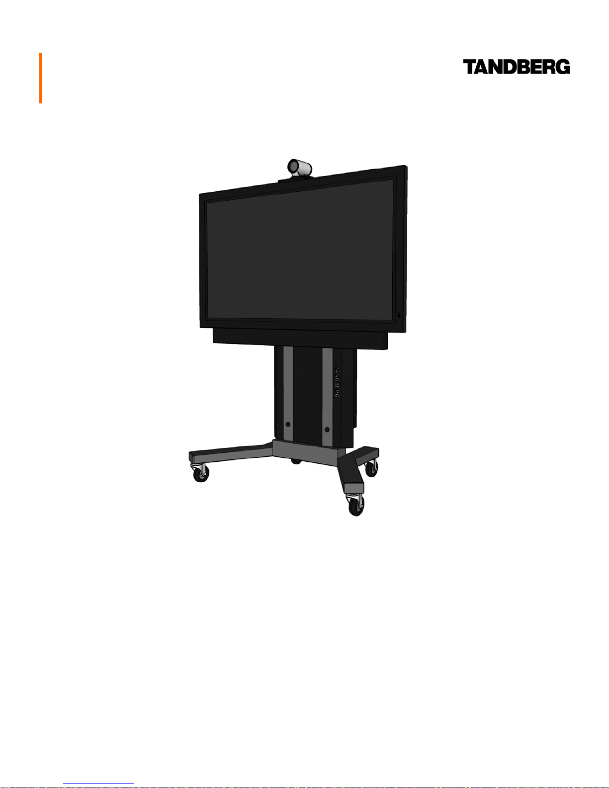
TANDBERG Scholar MXP
Assembly, Setup & User Guide
This document is not to be reproduced in whole or in part
without the permission in writing from TANDBERG.
Page 2

Trademarks & Copyright
Environmental Issues
All rights reserved. This document contains information
that is proprietary to TANDBERG. No part of this
publication may be reproduced, stored in a retrieval
system, or transmitted, in any form, or by any means,
electronically, mechanically, by photocopying, or
otherwise, without the prior written permission of
TANDBERG. Nationally and internationally recognized
trademarks and trade names are the property of their
respective holders and are hereby acknowledged.
Portions of this software are © 1996-2007 RADVISION
Ltd. All intellectual property rights in such portions of the
Software and documentation are owned by RADVISION
and are protected by United States copyright laws, other
applicable copyright laws and international treaty
provisions. RADVISION and its suppliers retain all rights
not expressly granted.
Contains iType™ from Agfa Monotype Corporation.
Disclaimer
The information in this document is furnished for
informational purposes only, is subject to change
without prior notice, and should not be construed as a
commitment by TANDBERG.
The information in this document is believed to be
accurate and reliable; however TANDBERG assumes no
responsibility or liability for any errors or inaccuracies
that may appear in this document, nor for any
infringements of patents or other rights of third parties
resulting from its use. No license is granted under any
patents or patent rights of TANDBERG.
Thank you for buying a product, which contributes to a
reduction in pollution, and thereby helps save the
environment. Our products reduce the need for travel and
transport and thereby reduce pollution. Our products have
either none or few consumable parts (chemicals, toner,
gas, paper). Our products are low energy consuming
products.
Battery handling
Batteries for the Remote Control are Long Life and Alkaline
batteries saving the environment; please follow guidelines
on the packing material for handling and disposal of the
batteries.
Waste handling
No need to send material back to TANDBERG as there are
no consumables to take care of. Please contact your local
dealer for information on recycling the product by sending
the main parts of the product for disassembly at local
electronic waste stations, marking recyclable parts so the
waste station can disassemble and re-use these parts.
Production of Products
Our factories employ the most efficient environmental
methods for reducing waste and pollution and ensuring the
products are recyclable.
Portions of this document written by the Solutions Group
of TANDBERG, U.S.A. and the Technical Support
Department of TANDBERG, Norway. We are committed
to maintaining a high level of quality in all our
documentation. Towards this effort, we welcome your
comments and suggestions regarding the content and
structure of this document. Please fax or mail your
comments and suggestions to the attention of:
TANDBERG Solutions Group
1860 Michael Faraday Drive, Suite 100
Reston, Virginia 20190
Tel: 703-709-4281, Fax: 703-709-4231
Page 3

OPERATOR SAFETY SUMMARY
For your protection, please read these safety instructions completely before operating the equipment and keep this
manual for future reference. The information in this summary is intended for operators. Carefully observe all warnings,
precautions and instructions both on the apparatus and in the operating instructions.
Warnings
• Water and moisture - Do not operate the
equipment under or near water - for example near
a bathtub, kitchen sink, or laundry tub, in a wet
basement, or near a swimming pool or in areas
with high humidity.
• Cleaning - Unplug the apparatus from the wall
outlet before cleaning or polishing. Do not use
liquid cleaners or aerosol cleaners. Use a lint-free
cloth lightly moistened with water for cleaning the
exterior of the apparatus.
• Ventilation - Do not block any of the ventilation
openings of the apparatus. Install in accordance
with the installation instructions. Never cover the
slots and openings with a cloth or other material.
Never install the apparatus near heat sources such
as radiators, heat registers, stoves, or other
apparatus (including amplifiers) that produce heat.
• Grounding or Polarization - Do not defeat the safety
purpose of the polarized or grounding-type plug. A
polarized plug has two blades with one wider than
the other. A grounding type plug has two blades
and a third grounding prong. The wide blade or
third prong is provided for your safety. If the
provided plug does not fit into your outlet, consult
an electrician.
• Power-Cord Protection - Route the power cord so as
to avoid it being walked on or pinched by items
placed upon or against it, paying particular
attention to the plugs, receptacles, and the point
where the cord exits from the apparatus.
• Accessories - Use only with a cart, stand, tripod,
bracket, or table specified by the manufacturer, or
sold with the apparatus. When a cart is used, use
caution when moving the cart/apparatus
combination to avoid injury from tip-over.
• Lightning - Unplug this apparatus during lightning
storms or when unused for long periods of time.
• ISDN cables - CAUTION - To reduce the risk of fire,
use only No. 26 AWG or larger telecommunication
line cord.
• Servicing - Do not attempt to service the apparatus
yourself as opening or removing covers may expose
you to dangerous voltages or other hazards, and
will void the warranty. Refer all servicing to
qualified service personnel.
• Damaged Equipment - Unplug the apparatus from
the outlet and refer servicing to qualified personnel
under the following conditions:
When the power cord or plug is damaged or frayed
If liquid has been spilled or objects have fallen into
the apparatus
If the apparatus has been exposed to rain or
moisture
If the apparatus has been subjected to excessive
shock by being dropped, or the cabinet has been
damaged
• Attachments - Only use attachments as
recommended by the manufacturer.
If the apparatus fails to operate in accordance with
the operating instructions
Page 4

TABLE OF CONTENTS
TRADEMARKS & COPYRIGHT ........................... 2
ENVIRONMENTAL ISSUES................................. 2
OPERATOR SAFETY SUMMARY......................... 3
TABLE OF CONTENTS........................................ 4
AT A GLANCE ..................................................... 5
TANDBERG SINGLE PLASMA CART ASSEMBLY
FOR SCHOLAR MXP........................................... 6
CONTROL WIRING DIAGRAM .......................... 15
AUDIO WIRING DIAGRAM................................ 16
VIDEO WIRING DIAGRAM ................................ 17
SYSTEM OVERVIEW......................................... 18
CONTROL INTERFACES................................... 18
AUDIO AND VIDEO SOURCES.......................... 18
TANDBERG SCHOLAR MXP SETUP GUIDE......20
SYSTEM CONFIGURATION | CODEC & TOUCH
PANEL ..............................................................20
CODEC CONFIGURATION..............................20
TOUCHPANEL CONFIGURATION...................22
TOUCH PANEL OPERATION..............................25
MAIN PAGE ...................................................25
MAKING A CALL ...............................................27
DIRECTORY DIAL ..........................................27
MANUAL DIAL ...............................................28
WHEN IN A CALL..............................................28
MAIN SOURCES............................................28
PRESENTATION ............................................29
FAR END CONTROL ......................................29
MULTISITE ....................................................30
DISCONNECTING A CALL..............................30
APPENDIX.........................................................31
INTEGRATING TANDBERG PRECISION HD
CAMERAS WITH THE OPTIONAL TANDBERG
VIDEO SWITCH..............................................31
OTHER COMPONENTS .................................... 19
Page 4 of 32 TANDBERG SCHOLAR ASSEMBLY, SETUP AND USER GUIDE | D50564.01
SERVICING .......................................................32
Page 5

AT A GLANCE
The TANDBERG Scholar MXP and videoconferencing solution is designed to be modular. The Scholar Electronics Rack
houses the TANBERG Applications Module MXP and the 6000 MXP codec, which are connected by an umbilical cable,
providing flexibility that allows this system to be setup in various locations with various equipment.
System Components
A full integration of the
TANDBERG Scholar MXP
system can include the
following:
such as DOC CAM and/or DVD Player)
Dual Display “Student” Carts
w/ Scholar Equipment Rack
(optional 2nd display)
Precision HD Camera
Touch Panel
Podium
(houses optional peripherals
Audio Science Microphone
(mounted on ceiling / optional)
Single Display “Instructor” Cart w/ PHD Camera
(optional)
The core components for the TANDBERG Scholar MXP system are:
• Scholar MXP Equipment Rack – TANDBERG 6000 MXP Codec, 1U shelf w/ power supplies, 1U Power Outlet
(The TANDBERG Video Switcher option will include a 1U Interface Panel in the rack.)
• 10” color touch panel with integrated 35’ cable containing power and control
• PHD Camera
• Table microphone
• Associated connection cables
Unpacking
To avoid damage to the system during transport the system is carefully packed and, in some cases, delivered as separate
components. Carefully unpack the components, cables, and accessories to prepare for installation and setup.
NOTE: Be sure to save the packaging in the event you need to transport the system to another location.
Page 5 of 32 TANDBERG SCHOLAR ASSEMBLY, SETUP AND USER GUIDE | D50564.01
Page 6
TANDBERG Single Plasma Cart Assembly for Scholar MXP
PARTS LIST
A. cart base with wheels
B. vertical support posts (2)
C. horizontal “U” channels (2)
D. handles (2)
E. beauty panel
F. speaker bar
G. display brackets (2)
H. TANDBERG Precision HD Camera
I. speaker bracket A (2)
J. speaker bracket B (2)
K. camera bracket
L. camera shelf
M. codec brackets (2)
N. J-hook
O. TANDBERG codec
P. display
Q. hardware for assembly
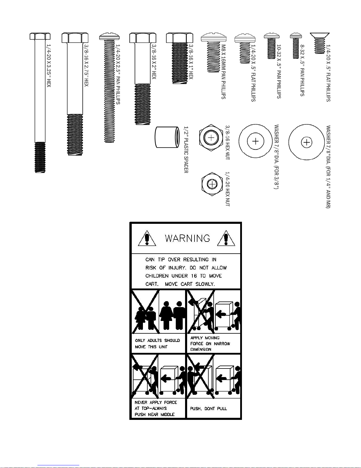
ASSEMBLY HARDWARE KIT
QTY DESCRIPTION
11 3/8-16 x 1" hex-head bolt grade 5
verticals to base, handles to horizontals & J-hook
29 washer for 3/8" bolt, 7/8" outside diameter
washers for all 3/8" and M8 bolts
4 3/8-16 x 2.75" hex-head bolt grade 5
horizontals to verticals
4 3/8-16 x 2" hex-head bolt grade 5
display mounting brackets to horizontals
6 M8 x 16 pan-head Phillips screw
display mounting brackets to plasma
2 1/4-20 x 3.25" hex-head bolt grade 5
mounting speaker bracket to verticals
10 1/4-20 hex-nut grade 5
mounting speaker bracket, beauty panel
4 washer for 1/4" screw, 7/8" outside diameter
mounting speaker bracket, beauty panel
12 washer for 1/4" screw, 7/8" outside diameter
mounting speaker bracket
2 nylon spacer for 1/4" screw, 1/2" long, 1/2" OD.
mounting speaker bracket
4 10-32 x .5” pan-head Phillips screw
codec brackets
4 1/4-20 screw, 2.5 pan-head Phillips
beauty panel
4 hinged screw cap for 1/4-20 screw
beauty panel
4 8-32 x 1/2” screw, pan-head Phillips
for Edge codec VESA bracket
1 vinyl-coated steel J-Hook (80lb. load)
attach to lower horizontal bar for cable management
5 3/8”-16 hex nut, grade 2
for handles, J-hook
4 ¼”-20 x ½” screw, Phillips
to attach User Control Module brackets
4 10-32 x 1/2" screw, pan Phillips
camera shelf to camera bracket / bracket to horizontal
4 #10 x .438OD washer
camera shelf to camera bracket / bracket to horizontal
1 1/4-20 x 1/2" screw, flat Phillips
camera shelf to HD camera
1 1” diameter adhesive back felt pad
camera shelf
Page 6 of 32 TANDBERG SCHOLAR ASSEMBLY, SETUP AND USER GUIDE | D50564.01
Page 7

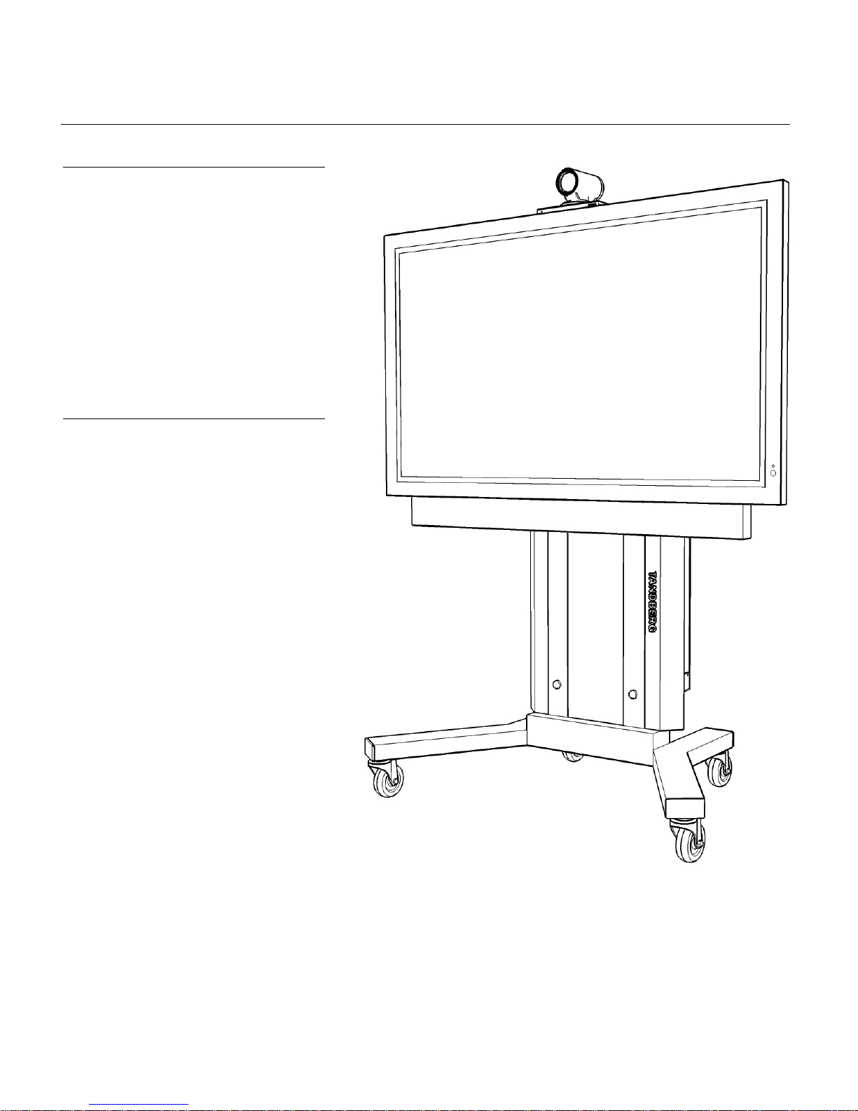
TANDBERG SCHOLAR MXP DISPLAY CART OVERVIEW
TANDBERG PRECISION HD CAMERA
CAMERA SHELF
CAMERA BRACKET
SPEAKER BRACKET (B) – 2X
HORIZONTAL “U” CHANNEL – 2X
DISPLAY
SPEAKER BAR
DISPLAY MOUNTING
BRACKET – 2X
DISPLAY BRACKET
ADAPTER – 4X
SPEAKER BRACKET (A) – 2X
VERTICAL SUPPORT POST – 2X
CART HANDLE – 2X
J-HOOK
CAPS – 4X
VESA MOUNT
BRACKET – 100MM
(OPTION)
CART BASE
COVER PANEL
WHEELS -- 4X
SCHOLAR MXP
EQUIPMENT RACK
Page 7 of 32 TANDBERG SCHOLAR ASSEMBLY, SETUP AND USER GUIDE | D50564.01
Page 8
TOOLS REQUIRED: 7/16 wrench or ratchet set
9/16 wrench or ratchet set
#2 Phillips screwdriver
Page 8 of 32 TANDBERG SCHOLAR ASSEMBLY, SETUP AND USER GUIDE | D50564.01
Page 9
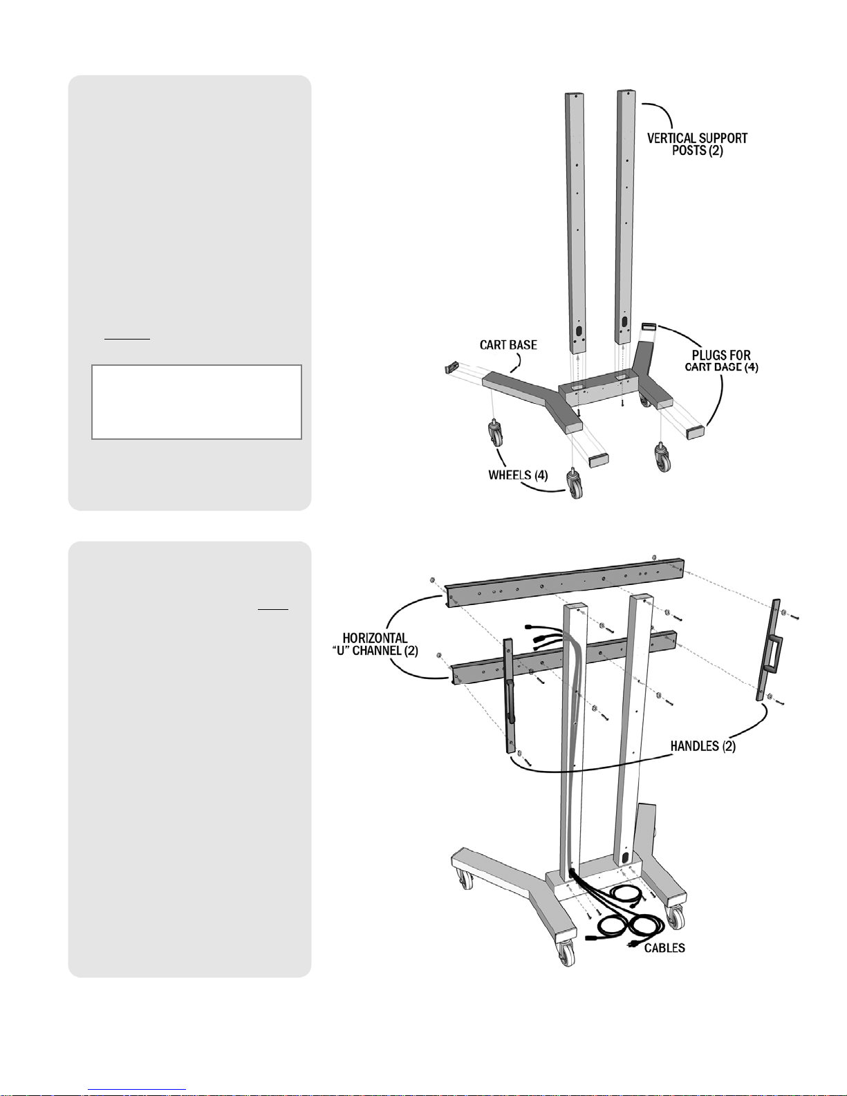
1. If needed, attach 4” WHEELS
(4) to the CART BASE using
supplied WHEELS and NUTS,
and if necessary, insert PLUGS
(4) into the open ends of the
CART BASE.
2. Position the VERTICAL
SUPPORT POSTS (2) into the
CART BASE as shown.
3. Use 3/8”–16 x 1” HEX BOLTS
& WASHERS (2) to secure the
VERTICAL POSTS to the
bottom of the cart.
NOTE: Ensure that the
WHEELS are set in the LOCK
position before proceeding.
4. Use 3/8”–16 x 1” HEX BOLTS
& WASHERS (4) to secure the
VERTICAL POSTS at the
back
of the cart.
5. Mount the HORIZONTAL “U”
CHANNELS (2) to the UPRIGHT
SUPPORT POSTS using 3/8”–
16 x 2¾“ HEX BOLTS and
WASHERS (4).
6. Fasten the cart’s HANDLES (2)
to the HORIZONTAL “U”
CHANNELS using 3/8”–16 x
1” HEX BOLTS, WASHERS, and
NUTS (4).
IT IS RECOMMENDED THAT
THE NECESSARY CABLES FOR
THE SYSTEM ARE RUN
THROUGH EITHER OR BOTH
VERTICAL POSTS AT THIS
TIME.
Refer to the WIRING DIAGRAM for
necessary cables to run per
system/room requirements.
Page 9 of 32 TANDBERG SCHOLAR ASSEMBLY, SETUP AND USER GUIDE | D50564.01
Page 10
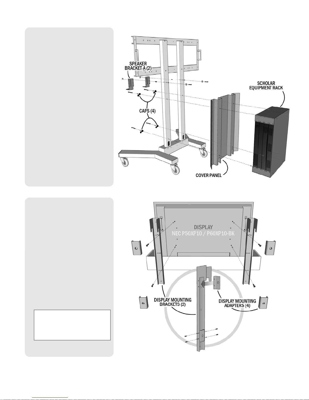
7. Insert the ¼“–20 x 2.5”
BOLTS (4) into the CAPS (4)
mounting the COVER PANEL
and the SCHOLAR EQUIPMENT
RACK to the VERTICAL POSTS.
8. Place the .5” SPACERS (2)
behind SPEAKER BRACKETS-A
(2) and mount them to each of
the POSTS using ¼”–20 x
3¼” BOLT & NUTS and ¼”
WASHERS (8).
DO NOT TIGHTEN SPEAKER
BRACKETS AT THIS TIME.
9. Remove the top cover for each
of the DISPLAY BOXES. Leave
the DISPLAY in the bottom
packaging for the next step.
10. Attach
*
the DISPLAY
MOUNTING BRACKETS (2) to
the rear of the DISPLAYS using
M8 x 16 BOLTS (4).
* When attaching the BRACKET to the
NEC displays you will need to remove
the DISPLAY MOUNTING ADAPTERS
(4) to access the appropriate
mounting holes for your particular
display. Replace the ADAPTERS when
BRACKETS are mounted.
NOTE: Use the INSIDE HOLES on
the DISPLAY MOUNTING
BRACKETS as shown to attach to
the DISPLAY.
Page 10 of 32 TANDBERG SCHOLAR ASSEMBLY, SETUP AND USER GUIDE | D50564.01
Page 11

MOUNTING POSITIONS FOR DISPLAYS
NEC P50XP10 (50”) / NEC P60XP10-BK (60”) / LG 50PM1M (50”)
LARGE HOLE =
MOUNTING
POINTS ON
HORIZONTAL
U-CHANNEL
SMALL HOLE =
MOUNTING
POINTS ON
DISPLAY
LARGE HOLE =
MOUNTING
POINTS ON
HORIZONTAL
U-CHANNEL
Page 11 of 32 TANDBERG SCHOLAR ASSEMBLY, SETUP AND USER GUIDE | D50564.01
SMALL HOLE =
MOUNTING
POINTS ON
DISPLAY
Page 12

MOUNTING POSITIONS FOR DISPLAYS
PIONEER PDP-507CMX (50”) / PIONEER PDP-607CMX (60”)
LARGE HOLE =
MOUNTING
POINTS ON
HORIZONTAL
U-CHANNEL
SMALL HOLE =
MOUNTING
POINTS ON
DISPLAY
LARGE HOLE =
MOUNTING
POINTS ON
HORIZONTAL
U-CHANNEL
Page 12 of 32 TANDBERG SCHOLAR ASSEMBLY, SETUP AND USER GUIDE | D50564.01
SMALL HOLE =
MOUNTING
POINTS ON
DISPLAY
Page 13

11. Lift* and hook the DISPLAY to
the top HORIZONTAL “U”
CHANNEL to mount onto the
CART.
* THIS REQUIRES THE SUPPORT
OF AT LEAST ANOTHER
PERSON TO LIFT AND MOUNT
THE HEAVY DISPLAY!
12. Use the 3/8”–16 x 2” BOLTS
(4) to secure the DISPLAY to
the FRAME.
13. Mount the J-HOOK with a
3/8”–16 x 1” BOLT, NUT, and
WASHER into
any spare hole
located on the HORIZONTAL
“U” CHANNEL.
14. Attach ADHESIVE-BACKED
FOAM to the
top-front of
SPEAKER BAR as shown and
trim any excess foam.
15. Attach SPEAKER BRACKETS-B
(2) to the SPEAKER BAR using
the EXISITING SCREWS (4).
16. Attach the SPEAKER CABLE to
the SPEAKER BAR.
17. Mount the SPEAKER BAR and
BRACKET-B to SPEAKER
BRACKET-A on the FRAME
using ¼”–20 NUTS and ¼”
WASHERS (4) with the existing
studs on BRACKET-A.
18. Adjust the SPEAKER BAR to
align with the DISPLAY’S front
and bottom and securely
tighten the screws.
Page 13 of 32 TANDBERG SCHOLAR ASSEMBLY, SETUP AND USER GUIDE | D50564.01
Page 14

y
19. Use the ¼”–20 x ½” SCREW
to secure the HD CAMERA to
the CAMERA SHELF*.
* Affix the FELT PAD to the center-front
area on the bottom of the CAMERA
SHELF to protect from scratching the
top of the DISPLAY.
20. Align the CAMERA BRACKET
with the bracket holes along
the top “U” CHANNEL and
secure the bracket using 1032 x .5” SCREWS (2).
21. Slide the CAMERA SHELF into
the CAMERA BRACKET and
secure the two parts together
with 10-32 x .5” SCREWS (2).
22. An OPTIONAL 100mm VESA
MOUNT BRACKET (2) can be
installed for mounting a VESA
compatible PC or other
peripheral device.
23. Use the WIRING DIAGRAM on
the following page to connect
the appropriate cables and
devices.
24.
Return the BACK PANEL to the
COLLABORATOR EQUIPMENT
RACK.
25.
The system assembly is
complete.
Please refer to the following
sections to complete system
setup and understand how to
operate the TANDBERG
Collaborator.
Please refer to the TANDBERG
CODEC MANUAL to set up and
configure the system’s codec
per the network requirements
our environment.
for
Page 14 of 32 TANDBERG SCHOLAR ASSEMBLY, SETUP AND USER GUIDE | D50564.01
Page 15

CONTROL WIRING DIAGRAM
Page 15 of 32 TANDBERG SCHOLAR ASSEMBLY, SETUP AND USER GUIDE | D50564.01
Page 16

AUDIO WIRING DIAGRAM
Page 16 of 32 TANDBERG SCHOLAR ASSEMBLY, SETUP AND USER GUIDE | D50564.01
Page 17

VIDEO WIRING DIAGRAM
Page 17 of 32 TANDBERG SCHOLAR ASSEMBLY, SETUP AND USER GUIDE | D50564.01
Page 18

SYSTEM OVERVIEW
The TANDBERG Scholar MXP videoconferencing system is comprised of the following: components for CONTROL,
components for AUDIO and VIDEO, and ancillary components that can be added to provide a richer videoconferencing and
presentation experience.
Control Interfaces
The TANDBERG videoconferencing system is easily controlled through the touch panel interface. The touch panel controls
all presentation and videoconferencing needs via the SCHOLAR MXP and the codec.
TOUCH PANEL
The 10” touch panel is incorporated to enable a user to configure and manage the presentation from a podium or desktop.
The touch panel incorporates single screen operation and a video window that displays current local and remote site
transmissions. The touch panel interface is intuitively designed to maximize presentation effectiveness.
WEB BROWSER
A separate web-based user interface for technician/diagnostic control is available. The embedded web interface loaded with
the controller requires an IP connection for web-based control.
TANDBERG SCHOLAR MXP CONTROL MODULE
The controller in the SCHOLAR MXP modules directs the codec, and enables control of multiple devices, such as room
cameras, VCR’s, DVD players, document cameras.
TANDBERG 6000 MXP CODEC
The Codec is the heart of the system. The main task for the Codec is the compression of outgoing video, audio and data, the
transmission of this information to the far end and the decompression of the incoming information -- hence the name Codec;
compression and decompression.
Audio and Video Sources
MAIN CAMERA & AUX CAMERA
The Main Camera is generally mounted on top of the primary display. The Main Camera is a high quality color camera
with a fast pan/tilt/zoom action. The Main Camera is controlled by the touch panel control, or the system’s infrared
remote control. You can pre-store up to 10 camera positions using Camera Presets (5 for the Main camera and 5 for
the Aux).
MICROPHONES
You may connect up to three microphones to your TANDBERG system. There are several microphone solutions that
can be integrated with your system:
AudioScience
Microphone
(optional)
TANDBERG's award-winning AudioScience microphone is a transparent, ceiling-mounted,
wide-coverage, boundary microphone, which can eliminate the need for table
microphones. It is designed to pick up the audio from all conference participants seated
within in its pick-up area, defined by hemisphere of approximately 14-foot (4.25m) radius
extended in front of, and to the sides of the microphone. Using the Automatic Gain Control
(AGC) on the codec maintains the audio signal level at a fixed value by attenuating strong
signals and amplifying weak signals.
Table
Microphones
Page 18 of 32 TANDBERG SCHOLAR ASSEMBLY, SETUP AND USER GUIDE | D50564.01
The optional high-quality table microphones are designed to lie on a table during a
videoconference. The ideal location for the microphone is on a flat surface at least 6.5 ft
(2m) from the front of the system. The microphone cable should always point towards the
system. The system will automatically equalize sound levels. Loud and soft voices are
picked up and transmitted to the far end at approximately the same level.
Page 19

SPEAKER BAR
Audio is heard through the SPEAKER BAR. It is connected to the display. The Scholar MXP Module supplies the audio
to the display.
DOCUMENT CAMERA
A composite video source is available for integrating an optional document
camera. Document cameras can be used to show a wide variety of media, such
as whitepapers, film negatives, or standard overhead projector transparencies.
Source selection, zoom, focus and lighting can all be controlled from the button
panel of the document camera.
If the document camera is one of the supported controllable devices and
configured, the document camera functions can be controlled from the touch
panel when that input is selected.
DVD/VCR PLAYER & RECORDER
Standard composite video VCR’s or DVD players can be added for playback and
recording. Using codec features such as audio “ducking” (lowering the VCR
output while the presenter is talking) allows seamless presentations and
participant interaction.
When configured, the device controls will be available on the touch panel. You
may also use the front panel controls or the supplied remote control specific to
these devices.
When recording is desired, select the “Record Control” button to bring up the
video source to record. You may choose to record the far or near end video as
the source being recorded. “Start Record” will begin the recording. Pressing stop
on the lower controls will stop the recording.
See the peripheral wiring diagram for the Scholar MXP to ensure proper connections for recording.
PC/LAPTOP COMPUTER
A user supplied PC or laptop can be connected to the system to enhance presentation. You can connect the
PC/laptop to the DVI input on the codec, or to a high-resolution document camera.
Other Components
ADDITIONAL MONITORS
An additional monitor can be added for viewing the far or local video. Typically
used to view the far side in a teaching environment, the monitor will also show
the local image when giving a local presentation.
On/Off controls of certain displays is available. Current some Epson, LG, and
pioneer devices can be turned on/off via RS-232 control to extend monitor life
and avoid screen burn in.
REMOTE CONTROL
The handheld TANDBERG Remote Control is used to control most functions of
the system. The system also emulates the remote control via the touch panel.
The reach of the remote control signal is 20 meters. For users sitting in an open plan office, this can cause problems.
Use the little, white switch placed under the batteries to change the reach of the signal from 20 meters to 2 meters.
This will prevent you from unintentionally controlling your neighbor's video system, when you control your own system.
Detailed instructions on how to use the TANDBERG Remote Control can be found in the codec manual.
Page 19 of 32 TANDBERG SCHOLAR ASSEMBLY, SETUP AND USER GUIDE | D50564.01
Page 20

TANDBERG Scholar MXP Setup Guide
Once the TANDBERG Scholar MXP cart has been assembled and all components and connections have been
made to the system, the system can be powered on:
1. Plug the system’s power cord into a power outlet.
2. Make sure the switch on the power distribution unit on the Scholar MXP Equipment Rack is turned ON.
3. Ensure that the Net/Video port on the touch panel is connected to the Scholar MXP Equipment Rack.
Once the system is powered-up, the touch panel will become active and run through a 15 second boot cycle.
The system is ready when the WELCOME SCREEN is displayed on the touch panel.
NOTE: Before proceeding with your system, be sure to provide basic setup and configuration for the
CODEC and TOUCHPANEL by following the procedures outlined below (SYSTEM
CONFIGURATION | CODEC & TOUCH PANEL).
System Configuration | Codec & Touch Panel
The system must be configured for each installation. Network, audio, and other codec configuration settings are made
using the TANDBERG Remote Control.
CODEC CONFIGURATION
NOTE: While the touch panel is the primary source for presentation operation, the
remote is required for codec setup and menu navigation. Video switching controlled by
the remote control will not always function properly. It is recommended that you use the
touch panel to control video switching.
You can access the remote control emulator on the touch panel by entering the SYSTEM
SETUP page and selecting System Setup > IR FUNCTION. Make sure you select the FAR
END SOURCE in the video window while in this screen to view the codec’s menu. This is
done by touching FAR in the window.
You may use either the physical remote control or the touch panel emulation of the remote control – both function
identically.
1. Press TOUCH TO START on the WELCOME PAGE after the system has run through its boot cycle.
2. Press the
point the remote in the direction of the camera as the IR sensor is located on the front of the camera.)
3. Navigate through the menu system using the
Menu.
NOTE: If an external IMUX or non-standard network is being used it may be necessary to configure any associated external
equipment.
NOTE: Refer the ‘TANDBERG 6000 MXP User Manual’ for detailed codec menu navigation and configuration.
Page 20 of 32 TANDBERG SCHOLAR ASSEMBLY, SETUP AND USER GUIDE | D50564.01
OK button on the remote control to display the ‘Main Menu’ on your main display monitor. (Be sure to
ARROW KEYS and OK. Press Cancel [ X ] to return to the previous
Page 21

General Codec Configuration:
1. Open the General Settings menu
a. Press OK on the remote to open the ‘Main Menu’ (if it is not already open).
b. Select ‘Control Panel’ and then select ‘Administrator Settings’.
c. Select ‘General’ to open the ‘General Settings’ menu.
2.
Language
Press OK in the Language field and select the language you want to use from the list. There are 13 languages to
choose from. The touch panel will only display English.
NOTE: This changes the language used on the menus of the codec only and not the touch panel!
3. System Name
Enter a name in the ‘System Name’ field using the number keys on the remote control, as you would do with a
mobile or cellular phone.
4.
Dual Monitor
If you are using two monitors, set Dual Monitor to On.
If you are using one
5. Auto Answer, Max Call Length, Global Phone Book Settings and Permissions
Leave Auto Answer, Max Call Length, Access code and Permissions unchanged if no special needs are required.
monitor, set Dual Monitor to Off.
6. Screen Settings
When using wide screen (16:9) monitors, set TV Monitor Format to Wide (16:9). TANDBERG also recommends
setting Picture Layout to Picture outside Picture when using 16:9 monitors. Picture outside Picture provides a
display layout optimized for wide screen monitors. The display layout may be changed at any time using the Layout
button on the remote control.
7. Software Options
To activate MultiSite and bandwidth, you must enter a new option key in the Software Options menu (see
paperwork accompanying your system). For more information on these options, contact your TANDBERG
representative.
8. Save changes
Remember to save any changes you make in a menu by selecting the Save button on the Menu line and pressing
OK.
Network configuration:
1. Open the Network menu
Open the ‘Administrator Settings’ menu and choose ‘Network’.
2. ISDN configuration
Set ‘Current Network’ to the network you want to use. Specify the settings for the selected network in the relevant
menu.
3. LAN configuration
In the ‘Administrator Settings’ menu, choose ‘Network and LAN Settings’. Specify the necessary LAN settings
according to the instructions from your LAN administrator.
4. Save changes
Remember to save any changes you make in a menu by selecting the Save button on the Menu line and pressing
OK.
Monitor volume:
1. Adjust monitor volume
Use the monitor remote control to adjust the volume of the monitors. This volume will be the default volume for all
calls.
Page 21 of 32 TANDBERG SCHOLAR ASSEMBLY, SETUP AND USER GUIDE | D50564.01
Page 22

TOUCHPANEL CONFIGURATION
System Setup
There are a number of setup options and
configurations that can be utilized to customize
and configure your system. Press the SETUP
button to enter the utilities and setup page.
IR FUNCTION Presents a page for remote control emulation.
CONFIGURE
SOURCES
PASSWORD
PROTECTION
DISPLAY
CONFIGURATION
SYSTEM
INFORMATION
EXIT Exits setup page and returns to the MAIN page.
DISPLAY POWER Powers down the display monitor(s) and puts the system/codec to sleep
Configure the peripheral devices that appear on the touch panel.
Setup password protection for access to dialing, system, and setup pages.
Configure display types to control.
General system information.
Page 22 of 32 TANDBERG SCHOLAR ASSEMBLY, SETUP AND USER GUIDE | D50564.01
Page 23

IR FUNCTIONS
Pressing this will present the TANDBERG Remote Control on the touch panel. Much of the remote’s functions are
emulated on this page to control the codec.
CONFIGURE SOURCES
Pressing CONFIGURE SOURCES provides source options
that can be defined to appear in the source list that shows
on the left side of the MAIN PAGE.
AUXILLARY CAMERA
Highlight this to enable the INSTRUCTOR CAM (AUX)
button to appear on the Main Page. This option should
be selected when a second camera is present.
PC/VGA INPUT
This option will show the PC source button on the Main
Page.
DOCUMENT CAMERA
Selecting this option will show a submenu to specify
which document camera that is connected to the
system is to be controlled from the touch panel. The
DOC CAM button will appear on the Main Page when
selected.
VCR/DVD
Selecting this source will show the VCR/DVD button on the Main Page. When this is selected, a submenu will appear to
specify which video playback device is connected to the system that is to be controlled from the touch panel.
PASSWORD PROTECTION
This selection provides three options to set and enable
passwords for the system: DIALING, SETUP, and SYSTEM
passwords can be set.
Press an option at the top of the page to toggle between
ENABLED (green) and DISABLED (red). The corresponding
password(s) can be set in the lower window using the
KEYPAD. The passwords are 4-digit number combinations.
When a password is set an enabled for:
DIALING
a password challenge will appear when the MAKE A
CALL button is pressed on the Main Page.
SETUP
a password challenge will appear when the SETUP
button is pressed on the Main Page.
SYSTEM
a password challenge will appear when the TOUCH TO START button is pressed (upon waking up the system or when
the system has been rebooted).
NOTE: the system’s default master password is 4263. This password can override any of the three password challenges on
the touchpanel.
Page 23 of 32 TANDBERG SCHOLAR ASSEMBLY, SETUP AND USER GUIDE | D50564.01
Page 24

DISPLAY CONFIGURATION
This selection allows for the setup of the specific display
monitors that can be power managed by the system.
SYSTEM INFORMATION
Pressing this will display general system information.
This information can be helpful when troubleshooting
with TANDBERG Technical Support.
Page 24 of 32 TANDBERG SCHOLAR ASSEMBLY, SETUP AND USER GUIDE | D50564.01
Page 25

USING THE SYSTEM
Touch Panel Operation
Upon start-up the interactive touch panel will display the INTRODUCTORY SPLASH
PAGE.
MAIN PAGE
The MAIN PAGE is the launching pad from which you will begin your presentation.
The following image describes what the user will initially see after start
VIDEO DISPLAY WINDOW
-up.
CALL CONTROL
MAIN SOURCE
SELECTION
LAYOUT OPTIONS
SOURCE CONTROLS
VOLUME CONTROL / MUTE
VIDEO DISPLAY WINDOW
This window will either display the currently selected video source or the received video from the far end. The
Local Video (Student Cam) is the default video source. When in a call, touching NEAR or FAR in the upper corners
of the video window will toggle between the two video sources.
LAYOUTS
Touching the LAYOUT button will toggle through the different display layouts that are available dependent on the
presentation scenario and how many call are connected.
Page 25 of 32 TANDBERG SCHOLAR ASSEMBLY, SETUP AND USER GUIDE | D50564.01
Page 26

SOURCE CONTROLS
This area presents the control options for the currently selected source.
MAIN SOURCE SELECTION
This area provides available sources to select from during presentation.
STUDENT
CAM
INSTRUCTOR
CAM
PC
DOC CAM
DVD/VCR
Local view. The camera controls appear in the SOURCE
CONTROL area.
When a second camera is connected and configured, this
source and its controls will appear in the SOURCE CONTROL
area.
Presents the content that is presented using a computer
(PC/MAC/other) that is connected to the system. No controls are
available.
Presents the content that is presented using the document
camera configured for the system. The DOC CAM controls
specific for the device that is configured will appear in the
SOURCE CONTROL area.
Presents the content that is presented through a VCR, DVD
player, or other A/V source connected to the system. The
controls specific to the VCR/DVD unit that is configured will
appear in the SOURCE CONTROL area. Any other A/V source will
not be controllable.
CALL CONTROL
This area provides the necessary options for presentation, as well as call control. Different functions will be
available when applicable.
MAKE A CALL
DISCONNECT
PRESENTATION
ADD SITE
SETUP
Access to the Directory and Manual Dial page.
Ends a call.
When in a call, the PRESENTATION button shows the
presentation source options to be viewed by the participants.
Touching ADD SITE will enable additional calls/sites to be
placed when already in a call. The system can accommodate a
total of 5 video sites (including you, the host) and an additional
3 audio/phone connections.
Access to the SYSTEM SETUP pages.
AUDIO
VOLUME
INDICATOR
MIC MUTE Mutes the local system microphone.
Page 26 of 32 TANDBERG SCHOLAR ASSEMBLY, SETUP AND USER GUIDE | D50564.01
Control the volume level for the system.
Page 27

Making a Call
Placing a videoconference call is a simple process:
1. Touch MAKE CALL to view dialing options.
2. Manually dial a number or select a directory entry to dial.
3. Press CONNECT to place the call.
DIRECTORY DIAL
When DIRECTORY DIAL is selected, a list of local, user-defined entries are presented.
1. Select the directory entry to call.
2. Press CONNECT.
Additional calls may be added by touching ADD CALL from the MAIN PAGE to begin a MultiSite session.
accommodate a total of 5 video sites (including you, the host) and an additional 3 audio/phone connections.
DIRECTORY SETUP
Touch DIRECTORY SETUP to ADD, EDIT, or DELETE directory
entries.
ADD
Touch ADD to enter the name and call requirements for the
new directory entry. Press SAVE ENTRY to include this entry
to the local directory.
EDIT
Touch the directory entry to be modified and touch EDIT
ENTRY. Modify as needed and press SAVE ENTRY.
DELETE
Touch the directory entry to be removed and touch DELETE
ENTRY. A confirmation page will appear to verify directory
entry removal.
The system can
NOTE: The directory entries are stored locally on the touch panel. While the Scholar MXP does not support the retrieval
of Global or Corporate Global Directories, the local touch panel directory can be synchronized with the codec’s directory
by touching RETREIVE CODEC DIRECTORY on the DIRECTORY SETUP page.
Page 27 of 32 TANDBERG SCHOLAR ASSEMBLY, SETUP AND USER GUIDE | D50564.01
Page 28

MANUAL DIAL
When placing a call that is not in the directory, touch the MANUAL DIAL button to enter the required call information.
1.
Enter the NUMBER or ADDRESS you wish to dial. You may enter any combination of alphanumeric* characters.
2.
Enter any call options necessary:
3.
Press CONNECT to dial the number.
When In a Call
When a call has been placed and connected, the system will display the MAIN PAGE. You can choose to:
use the MAIN SOURCES to show
your content/presentation
disconnect your call by touching
enhance your presentation with
add additional sites for a MultiSite
MAIN SOURCES
Selecting a MAIN SOURCE will display the content on the system’s display:
STUDENT
CAM
INSTRUCTOR
CAM
Local view. The camera controls appear in the SOURCE
CONTROL area.
When a second camera is connected and configured, this
source and its controls will appear in the SOURCE CONTROL
area.
DISCONNECT
dual streams (H.239) by touching
PRESENTATION
videoconference call by touching
ADD SITES. (requires MultiSite
option to be installed).
PC
DOC CAM
DVD/VCR
Page 28 of 32 TANDBERG SCHOLAR ASSEMBLY, SETUP AND USER GUIDE | D50564.01
Presents the content that is presented using a computer
(PC/MAC/other) that is connected to the system. No controls are
available.
Presents the content that is presented using the document
camera configured for the system. The DOC CAM controls
specific for the device that is configured will appear in the
SOURCE CONTROL area.
Presents the content that is presented through a VCR, DVD
player, or other A/V source connected to the system. The
controls specific to the VCR/DVD unit that is configured will
appear in the SOURCE CONTROL area. Any other A/V source will
not be controllable.
Page 29

PRESENTATION
Utilizing the PRESENTATION tool can be an effective way to present content other than through the MAIN
CAMERA. You are now able to present contents of a connected PC/laptop computer, a document
camera, or a video clip from a VCR or DVD player with a second stream, while the main camera can be
utilized to maintain “eye-contact” with the
1. While in a videoconference call, press PRESENTATION. If the button is not present, you are not able to initiate a
Presentation session at this time
2. The Presentation page will appear. You will see source selections for the MAIN video display, as well as the
source selections for the PRESENTATION display.
audience.
3. Select the desired PRESENTATION source you wish to present. The far-end site will be able to see your selected
source.
4. Press PRESENTATION again to discontinue sending a presentation source. This will not disconnect your call.
FAR END CONTROL
It is possible to get some control of the far end system. This allows for
control of the conference partner’s camera, video sources and
presets. Enabling Far End Control in the codec’s ‘Control Panel’ will
allow the system to do Far End camera control and camera presets
on the far end camera. See Far End Control in the TANDBERG 6000
MXP Manual for more details.
You can initiate Far End Control using your touch panel only if the Far
End has been properly configured.
Press the FAR END button to view the FAR END CONTROLS (purple). If the Far End is not configured to do, the touch panel
will display “Far End Control Not Possible.” (You may ask the Far End participant to enable Far End Control via their
codec’s Control Panel.)
Page 29 of 32 TANDBERG SCHOLAR ASSEMBLY, SETUP AND USER GUIDE | D50564.01
Page 30

MULTISITE
The optional MultiSite capability enables several sites to participate in the same conference. You can have a maximum of
5 video- and 3 telephone-participants including yourself (the host). The participants are tiled up on the screen and are on
display simultaneously in a Split Screen. During an MCU conference, the status line will provide information about the
conference.
A MultiSite conference can be established in different ways. The MultiSite Services vary depending on how you make the
call. Refer to the TANDBERG 6000 MXP User Manual for more about MultiSite and MCU Services.
1. While in a call, press ADD SITE and select a directory entry or enter a number manually.
2. Press CONNECT.
Repeat steps 1 and 2 if you would like to connect additional sites. You can add a site at any time by entering the CALL
CONTROL page.
3. Operate the conference as normal.
DISCONNECTING A CALL
Pressing the red DISCONNECT button during a call will prompt you to confirm the termination of that call before the
connection is terminated.
When in a MultiSite call, pressing the DISCONNECT button will allow you to choose to disconnect individual sites, or to
disconnect the entire MultiSite session.
Page 30 of 32 TANDBERG SCHOLAR ASSEMBLY, SETUP AND USER GUIDE | D50564.01
Page 31

•
APPENDIX
Integrating TANDBERG Precision HD Cameras with the
optional TANDBERG Video Switch
Up to two TANDBERG PHD Cameras can be integrated into this system (SCHOLAR MXP), using the TANDBERG Video Switch
(TVS), to provide high-definition video. The TVS enables the system to switch between the HD camera signals.
These cameras correspond to MAIN and AUX.
CAMERA OPTIONS
SOURCE INPUT CAMERA DETECTED USES TVS INPUT CONTROL CONNECTION CABLE
Camera #1 Precision HD DVI-D #1 Via TVS “Data 1 HD” 115420 (6’) C6000
Camera #2 Precision HD DVI-D #2 Direct via Display 2 breakout Use adapter T278-0008
Camera #1 Ctrl
To Codec Dataport 2
DVI Cabling: The DVI connections
to the TVS are Digital only (DVID)
• Power: Each camera and the TVS
will require a 12VDC power
supply.
Auxiliary #1, DVI 3 or RGB 6
Camera #1
Camera #2, DVI 2 or RGB 5
• TRC4 Remote Control: This
remote can be used but the
direct video input switch buttons
will not function correctly with
the TAM MXP.
TANDBERG recommends rack mounting the TVS within 6’ (1.5m) of the codec. If you have the TANDBERG student cart,
there is 1U blank panel above the codec, or on the 1U shelf. The power distribution bars behind the PC connection should
have adequate outlets available.
The TVS OUTPUT connects to the codec digital input on DATAPORT #2 replacing the existing Precision camera which now
connects to CAMERA 1.
CAMERA 1 (MAIN/STUDENT) connects to DVI-D 1 and control to DATA 1 HD
CAMERA 2 (AUX/INSTRUCTOR) connects to DVI-D 2 for the Precision HD Camera.
DISTANCE CONSIDERATIONS
If using the Precision HD camera as an instructor camera (looking at one specific person), it should be no further than 30’
(9m) from the subject due to the zoom capabilities of the camera.
CONNECTION DIAGRAM WITH TANDBERG VIDEO SWITCH
The schematic on the following page will show how the TVS is to be integrated with the TANDBERG Precision HD cameras.
Please note that the connections are different from the non-HD connection diagram (D5034602).
Page 31 of 32 TANDBERG SCHOLAR ASSEMBLY, SETUP AND USER GUIDE | D50564.01
Page 32

SERVICING
Do not attempt to service the TANDBERG system yourself, otherwise the warranty will be voided. Opening or
removing covers may expose you to dangerous voltage or other hazards. Refer all servicing t o qualified service
personnel.
Damage Requiring Service
Unplug the apparatus from the outlet and refer servicing to qualified personnel under the following conditions:
When the power cord or plug is damaged or frayed.
If liquid has been spilled or an object has fallen into the apparatus.
If the apparatus has been exposed to rain or moisture.
If the apparatus has been subject to excessive shock by being dropped.
If the apparatus does not operate normally when following the operating instructions.
NOTE: TANDBERG will provide on request circuit diagrams and component parts list of the system.
For servicing, please call one of the following service centers:
USA
TANDBERG Inc.
1860 Michael Faraday Drive
Suite 100
Reston, Virginia, USA 20190
Tel: 703-709-4281
Toll free: 800 889 7440
Fax: 703-709-4231
Video: 703 437 6991
Canada
TANDBERG Canada Inc.
6505 TransCanada Highway
Montreal, Quebec
H4T 1S3
Tel: 514 748 5224
Fax: 514 748 1002
Video: 514 748 7790
Page 32 of 32 TANDBERG SCHOLAR ASSEMBLY, SETUP AND USER GUIDE | D50564.01
 Loading...