

Page 1

TANDBERG FieldView™ delivers the
most innovative solution in mobile video
collaboration.
Featuring integrated wireless LAN, high
resolution video and audio and the ability to
collaborate via instant on-screen annotation—
it’s the next best thing to having your experts
on the scene.
Its ability to access small spaces enables
productivity in areas previously inaccessible by
video, allowing organizations to address and
resolve issues instantly.
Recording capabilities enable device and PC
users to archive material for a later date or
collaborate over previously recorded material.
FieldView
Administrator
Guide
D14098.02 June 2008
Software version 3.1
Page 2

The TANDBERG FieldView Device and the software
contained in and used with the TANDBERG FieldView
Device is subject to the following notices:
Copyright © 2004–2008 LibreStream Technologies Incorporated.
All rights reserved.
Patents Notice: United States Patent # 7,221,386, together
with additional patents pending in Canada, the United States
and other countries, all of which are in the name of LibreStream
Technologies Inc.
TANDBERG is a registered trademark of Tandberg ASA. All other
trademarks are the property of their respective owners.
About this document: All rights reserved. This document contains information that is proprietary
to TANDBERG. No part of this publication may be reproduced, stored in a retrieval system, or
transmitted, in any form, or by any means, electronically, mechanically, by photocopying, or
otherwise, without the prior written permission of TANDBERG. Nationally and internationally
recognized trademarks and trade names are the property of their respective holders and are hereby
acknowledged.
Copyright © 2008 TANDBERG
Contact information:
TANDBERG
Philip Pedersens vei 20, 1366 Lysaker, Norway
Telephone: +47 67 125 125
Fax: +47 67 125 234
Video: +47 67 126 126
E-mail: tandberg@tandberg.com
Page 3

TANDBERG FieldView Administrator Guide
Table of Contents
1. Introduction . . . . . . . . . . . . . . . . . . . . . . . . . . . . . . . . . . . . . . . . . . .1
About This Guide . . . . . . . . . . . . . . . . . . . . . . . . . . . . . . . . . . . . . . . . . .1
FieldView Architecture . . . . . . . . . . . . . . . . . . . . . . . . . . . . . . . . . . . . . . . 1
Overview of the TANDBERG FieldView Device . . . . . . . . . . . . . . . . . . . . . . .2
Overview of the TANDBERG FieldView Application . . . . . . . . . . . . . . . . . . . .3
Overview of the FMS . . . . . . . . . . . . . . . . . . . . . . . . . . . . . . . . . . . . . . . .3
Overview of the FES . . . . . . . . . . . . . . . . . . . . . . . . . . . . . . . . . . . . . . . .3
2. Installation . . . . . . . . . . . . . . . . . . . . . . . . . . . . . . . . . . . . . . . . . . . .4
TANDBERG FieldView Device Installation . . . . . . . . . . . . . . . . . . . . . . . . . .4
Power . . . . . . . . . . . . . . . . . . . . . . . . . . . . . . . . . . . . . . . . . . . . . . . . . .4
Battery Specifications . . . . . . . . . . . . . . . . . . . . . . . . . . . . . . . . . . . . . . .4
External Power Adaptor . . . . . . . . . . . . . . . . . . . . . . . . . . . . . . . . . . . . . .5
TANDBERG FieldView Device Input/Output Interfaces . . . . . . . . . . . . . . . . . 5
Accessories . . . . . . . . . . . . . . . . . . . . . . . . . . . . . . . . . . . . . . . . . . . . . . 7
TANDBERG FieldView Application Installation . . . . . . . . . . . . . . . . . . . . . . .7
First Steps Before Installation . . . . . . . . . . . . . . . . . . . . . . . . . . . . . . . . .8
Installing the TANDBERG FieldView Application Software . . . . . . . . . . . . . . .8
Coexistence with Security Software . . . . . . . . . . . . . . . . . . . . . . . . . . . . . 8
Removing the TANDBERG FieldView Application Software . . . . . . . . . . . . . .9
Infrastructure Installation . . . . . . . . . . . . . . . . . . . . . . . . . . . . . . . . . . . . 9
3. FieldView Network Architecture . . . . . . . . . . . . . . . . . . . . . . . . . . .10
Network Overview. . . . . . . . . . . . . . . . . . . . . . . . . . . . . . . . . . . . . . . . .10
FieldView Network Protocols and Port Usage . . . . . . . . . . . . . . . . . . . . . . 10
Wireless Networking . . . . . . . . . . . . . . . . . . . . . . . . . . . . . . . . . . . . . . . 11
Overview . . . . . . . . . . . . . . . . . . . . . . . . . . . . . . . . . . . . . . . . . . . . . . . 11
Perspective—Is all this really necessary? . . . . . . . . . . . . . . . . . . . . . . . . . 11
The Importance of Proper Infrastructure . . . . . . . . . . . . . . . . . . . . . . . . . 12
Special Needs for Voice and Video . . . . . . . . . . . . . . . . . . . . . . . . . . . . . 12
Radio Frequency Channel Selection . . . . . . . . . . . . . . . . . . . . . . . . . . . . . 13
Interference . . . . . . . . . . . . . . . . . . . . . . . . . . . . . . . . . . . . . . . . . . . . . 13
Wireless Coverage . . . . . . . . . . . . . . . . . . . . . . . . . . . . . . . . . . . . . . . . 14
Effect of Topography on Coverage . . . . . . . . . . . . . . . . . . . . . . . . . . . . . . 14
Signal to Noise Ratio . . . . . . . . . . . . . . . . . . . . . . . . . . . . . . . . . . . . . . . 14
Other Factors Affecting Coverage . . . . . . . . . . . . . . . . . . . . . . . . . . . . . . 14
Wireless Coverage of Large Areas . . . . . . . . . . . . . . . . . . . . . . . . . . . . . . 15
Capacity . . . . . . . . . . . . . . . . . . . . . . . . . . . . . . . . . . . . . . . . . . . . . . . 15
Improving Performance . . . . . . . . . . . . . . . . . . . . . . . . . . . . . . . . . . . . . 15
Site Survey . . . . . . . . . . . . . . . . . . . . . . . . . . . . . . . . . . . . . . . . . . . . . 16
Wireless Security . . . . . . . . . . . . . . . . . . . . . . . . . . . . . . . . . . . . . . . . . 16
Wireless Troubleshooting . . . . . . . . . . . . . . . . . . . . . . . . . . . . . . . . . . . . 16
Firewalls and Network Address Translation . . . . . . . . . . . . . . . . . . . . . . . . 16
4. TANDBERG FieldView Device . . . . . . . . . . . . . . . . . . . . . . . . . . . . .17
Configuration . . . . . . . . . . . . . . . . . . . . . . . . . . . . . . . . . . . . . . . . . . . . 17
Quick Setup for Basic Wireless Operation . . . . . . . . . . . . . . . . . . . . . . . . 17
D14098.02 June 2008
i
Page 4

TANDBERG FieldView Administrator Guide
Preparation . . . . . . . . . . . . . . . . . . . . . . . . . . . . . . . . . . . . . . . . . . . . . 17
Configuration . . . . . . . . . . . . . . . . . . . . . . . . . . . . . . . . . . . . . . . . . . . . 17
Configuration Options . . . . . . . . . . . . . . . . . . . . . . . . . . . . . . . . . . . . . . 19
Accessing the Configuration Window . . . . . . . . . . . . . . . . . . . . . . . . . . . . 19
Accepting and Canceling Configuration Changes . . . . . . . . . . . . . . . . . . . . 20
General . . . . . . . . . . . . . . . . . . . . . . . . . . . . . . . . . . . . . . . . . . . . . . . . 20
General>Device Name. . . . . . . . . . . . . . . . . . . . . . . . . . . . . . . . . . . . . .20
General>Power . . . . . . . . . . . . . . . . . . . . . . . . . . . . . . . . . . . . . . . . . . . 20
General>Media . . . . . . . . . . . . . . . . . . . . . . . . . . . . . . . . . . . . . . . . . . . 21
Display . . . . . . . . . . . . . . . . . . . . . . . . . . . . . . . . . . . . . . . . . . . . . . . . 21
Display>General . . . . . . . . . . . . . . . . . . . . . . . . . . . . . . . . . . . . . . . . . . 21
Display>Backlight . . . . . . . . . . . . . . . . . . . . . . . . . . . . . . . . . . . . . . . . . 22
Video . . . . . . . . . . . . . . . . . . . . . . . . . . . . . . . . . . . . . . . . . . . . . . . . . . 22
Video>Color . . . . . . . . . . . . . . . . . . . . . . . . . . . . . . . . . . . . . . . . . . . . . 22
Video>Source . . . . . . . . . . . . . . . . . . . . . . . . . . . . . . . . . . . . . . . . . . . . 22
Audio . . . . . . . . . . . . . . . . . . . . . . . . . . . . . . . . . . . . . . . . . . . . . . . . . . 23
Audio>General . . . . . . . . . . . . . . . . . . . . . . . . . . . . . . . . . . . . . . . . . . . 23
Audio>Volumes . . . . . . . . . . . . . . . . . . . . . . . . . . . . . . . . . . . . . . . . . . 23
Call Control . . . . . . . . . . . . . . . . . . . . . . . . . . . . . . . . . . . . . . . . . . . . . 24
Call Control>General . . . . . . . . . . . . . . . . . . . . . . . . . . . . . . . . . . . . . . . 24
Call Control>SIP . . . . . . . . . . . . . . . . . . . . . . . . . . . . . . . . . . . . . . . . . . 24
Call Control>SIP Settings . . . . . . . . . . . . . . . . . . . . . . . . . . . . . . . . . . . 25
Network . . . . . . . . . . . . . . . . . . . . . . . . . . . . . . . . . . . . . . . . . . . . . . . 25
Network>Wireless . . . . . . . . . . . . . . . . . . . . . . . . . . . . . . . . . . . . . . . . . 25
CF8385PN1 – Wireless Information . . . . . . . . . . . . . . . . . . . . . . . . . . . . . 26
Wireless Network Properties . . . . . . . . . . . . . . . . . . . . . . . . . . . . . . . . . . 26
Advanced Wireless Settings . . . . . . . . . . . . . . . . . . . . . . . . . . . . . . . . . . 27
CF8385PN1—IP Information . . . . . . . . . . . . . . . . . . . . . . . . . . . . . . . . . . 27
Network>Radio . . . . . . . . . . . . . . . . . . . . . . . . . . . . . . . . . . . . . . . . . . . 28
Network>SNMP . . . . . . . . . . . . . . . . . . . . . . . . . . . . . . . . . . . . . . . . . . 28
Security . . . . . . . . . . . . . . . . . . . . . . . . . . . . . . . . . . . . . . . . . . . . . . . . 28
Security>Login . . . . . . . . . . . . . . . . . . . . . . . . . . . . . . . . . . . . . . . . . . . 28
Security>Certificates . . . . . . . . . . . . . . . . . . . . . . . . . . . . . . . . . . . . . . . 29
Security>Encryption . . . . . . . . . . . . . . . . . . . . . . . . . . . . . . . . . . . . . . . 30
Time . . . . . . . . . . . . . . . . . . . . . . . . . . . . . . . . . . . . . . . . . . . . . . . . . . 30
Time>Time/Date . . . . . . . . . . . . . . . . . . . . . . . . . . . . . . . . . . . . . . . . . 30
Time>Zone . . . . . . . . . . . . . . . . . . . . . . . . . . . . . . . . . . . . . . . . . . . . . 30
Information . . . . . . . . . . . . . . . . . . . . . . . . . . . . . . . . . . . . . . . . . . . . . 30
Information>Versions . . . . . . . . . . . . . . . . . . . . . . . . . . . . . . . . . . . . . . 30
Information>Copyright . . . . . . . . . . . . . . . . . . . . . . . . . . . . . . . . . . . . . 30
Maintenance . . . . . . . . . . . . . . . . . . . . . . . . . . . . . . . . . . . . . . . . . . . . . 31
Maintenance>Update . . . . . . . . . . . . . . . . . . . . . . . . . . . . . . . . . . . . . . 31
Maintenance>Import . . . . . . . . . . . . . . . . . . . . . . . . . . . . . . . . . . . . . . . 31
Maintenance>Password . . . . . . . . . . . . . . . . . . . . . . . . . . . . . . . . . . . . . 32
Maintenance>Call History . . . . . . . . . . . . . . . . . . . . . . . . . . . . . . . . . . . 32
Recommendations and Tips . . . . . . . . . . . . . . . . . . . . . . . . . . . . . . . . . . 33
5. TANDBERG FieldView Application Configuration . . . . . . . . . . . . . .34
Preferences Configuration . . . . . . . . . . . . . . . . . . . . . . . . . . . . . . . . . . . 34
D14098.02 June 2008
ii
Page 5

TANDBERG FieldView Administrator Guide
Startup . . . . . . . . . . . . . . . . . . . . . . . . . . . . . . . . . . . . . . . . . . . . . . . . 34
Connections Window . . . . . . . . . . . . . . . . . . . . . . . . . . . . . . . . . . . . . . . 35
Call Window . . . . . . . . . . . . . . . . . . . . . . . . . . . . . . . . . . . . . . . . . . . . . 35
Paths . . . . . . . . . . . . . . . . . . . . . . . . . . . . . . . . . . . . . . . . . . . . . . . . . . 36
Sounds . . . . . . . . . . . . . . . . . . . . . . . . . . . . . . . . . . . . . . . . . . . . . . . . 36
Devices . . . . . . . . . . . . . . . . . . . . . . . . . . . . . . . . . . . . . . . . . . . . . . . . 37
Security . . . . . . . . . . . . . . . . . . . . . . . . . . . . . . . . . . . . . . . . . . . . . . . . 37
File Locations . . . . . . . . . . . . . . . . . . . . . . . . . . . . . . . . . . . . . . . . . . . . 38
6. Media Configuration . . . . . . . . . . . . . . . . . . . . . . . . . . . . . . . . . . . .39
Built-in Media Configurations . . . . . . . . . . . . . . . . . . . . . . . . . . . . . . . . . 39
About Media Configuration . . . . . . . . . . . . . . . . . . . . . . . . . . . . . . . . . . . 40
Understanding the Media Configuration Parameters . . . . . . . . . . . . . . . . . 40
Device Type . . . . . . . . . . . . . . . . . . . . . . . . . . . . . . . . . . . . . . . . . . . . . 40
Bit Rate . . . . . . . . . . . . . . . . . . . . . . . . . . . . . . . . . . . . . . . . . . . . . . . . 40
Video Size . . . . . . . . . . . . . . . . . . . . . . . . . . . . . . . . . . . . . . . . . . . . . . 41
Frame Rate . . . . . . . . . . . . . . . . . . . . . . . . . . . . . . . . . . . . . . . . . . . . . 41
MPEG-4 Frame Types . . . . . . . . . . . . . . . . . . . . . . . . . . . . . . . . . . . . . . 41
MPEG-4 Visual and Temporal Artifacts . . . . . . . . . . . . . . . . . . . . . . . . . . . 42
MPEG-4 Group Of Picture . . . . . . . . . . . . . . . . . . . . . . . . . . . . . . . . . . . . 42
Guidelines for Using Media Configurations . . . . . . . . . . . . . . . . . . . . . . . . 42
Exporting Media Configuration Parameters . . . . . . . . . . . . . . . . . . . . . . . . 43
7. User and Contact Management and Distribution . . . . . . . . . . . . . .44
Users and Contacts Overview . . . . . . . . . . . . . . . . . . . . . . . . . . . . . . . . . 44
User Information . . . . . . . . . . . . . . . . . . . . . . . . . . . . . . . . . . . . . . . . . 44
Contact Information . . . . . . . . . . . . . . . . . . . . . . . . . . . . . . . . . . . . . . . 45
Creating User and Contact Lists . . . . . . . . . . . . . . . . . . . . . . . . . . . . . . . 45
Copying Registration File to TANDBERG FieldView Device . . . . . . . . . . . . . 46
8. Maintenance . . . . . . . . . . . . . . . . . . . . . . . . . . . . . . . . . . . . . . . . . .47
Software Updates . . . . . . . . . . . . . . . . . . . . . . . . . . . . . . . . . . . . . . . . . 47
TANDBERG FieldView Device Software Updates . . . . . . . . . . . . . . . . . . . . 47
TANDBERG FieldView Application Updates . . . . . . . . . . . . . . . . . . . . . . . . 48
Batteries . . . . . . . . . . . . . . . . . . . . . . . . . . . . . . . . . . . . . . . . . . . . . . . 48
Battery Removal . . . . . . . . . . . . . . . . . . . . . . . . . . . . . . . . . . . . . . . . . . 48
Improving Battery Life . . . . . . . . . . . . . . . . . . . . . . . . . . . . . . . . . . . . . . 48
SD Cards . . . . . . . . . . . . . . . . . . . . . . . . . . . . . . . . . . . . . . . . . . . . . . . 49
SD Format . . . . . . . . . . . . . . . . . . . . . . . . . . . . . . . . . . . . . . . . . . . . . . 49
Preventative Maintenance . . . . . . . . . . . . . . . . . . . . . . . . . . . . . . . . . . . 49
General Recommendations . . . . . . . . . . . . . . . . . . . . . . . . . . . . . . . . . . 49
Viewfinder/Touch Screen . . . . . . . . . . . . . . . . . . . . . . . . . . . . . . . . . . . . 50
Optics . . . . . . . . . . . . . . . . . . . . . . . . . . . . . . . . . . . . . . . . . . . . . . . . . 50
Ergonomic Recommendations . . . . . . . . . . . . . . . . . . . . . . . . . . . . . . . . 50
9. Troubleshooting . . . . . . . . . . . . . . . . . . . . . . . . . . . . . . . . . . . . . . .51
Reset TANDBERG FieldView Device . . . . . . . . . . . . . . . . . . . . . . . . . . . . . 51
Soft reset . . . . . . . . . . . . . . . . . . . . . . . . . . . . . . . . . . . . . . . . . . . . . . . 51
Hard Reset . . . . . . . . . . . . . . . . . . . . . . . . . . . . . . . . . . . . . . . . . . . . . . 51
PC Log Files . . . . . . . . . . . . . . . . . . . . . . . . . . . . . . . . . . . . . . . . . . . . . 51
D14098.02 June 2008
iii
Page 6

TANDBERG FieldView Administrator Guide
Firewall and Anti-Spyware Blocking . . . . . . . . . . . . . . . . . . . . . . . . . . . . . 51
Checking wireless signal . . . . . . . . . . . . . . . . . . . . . . . . . . . . . . . . . . . . 52
Wireless Bar graph on Status Bar . . . . . . . . . . . . . . . . . . . . . . . . . . . . . 52
Network Status . . . . . . . . . . . . . . . . . . . . . . . . . . . . . . . . . . . . . . . . . . . 52
Stream Status . . . . . . . . . . . . . . . . . . . . . . . . . . . . . . . . . . . . . . . . . . . 53
Wireless Information . . . . . . . . . . . . . . . . . . . . . . . . . . . . . . . . . . . . . . . 53
Recommended diagnostic tools. . . . . . . . . . . . . . . . . . . . . . . . . . . . . . . .53
TANDBERG FieldView Device and TANDBERG FieldView Application
Troubleshooting . . . . . . . . . . . . . . . . . . . . . . . . . . . . . . . . . . . . . . . . . . 55
TANDBERG FieldView Device Troubleshooting . . . . . . . . . . . . . . . . . . . . . . 55
TANDBERG FieldView Application Troubleshooting . . . . . . . . . . . . . . . . . . . 65
Appendix A TANDBERG FieldView Device Technical Specifications . .67
System Architecture . . . . . . . . . . . . . . . . . . . . . . . . . . . . . . . . . . . . . . . 67
Physical Characteristics . . . . . . . . . . . . . . . . . . . . . . . . . . . . . . . . . . . . . 67
Optical Performance . . . . . . . . . . . . . . . . . . . . . . . . . . . . . . . . . . . . . . . 67
Video Standard . . . . . . . . . . . . . . . . . . . . . . . . . . . . . . . . . . . . . . . . . . . 67
User Interface & Features . . . . . . . . . . . . . . . . . . . . . . . . . . . . . . . . . . . 67
Collaboration Features . . . . . . . . . . . . . . . . . . . . . . . . . . . . . . . . . . . . . . 68
Audio Features . . . . . . . . . . . . . . . . . . . . . . . . . . . . . . . . . . . . . . . . . . . 68
Audio Standards . . . . . . . . . . . . . . . . . . . . . . . . . . . . . . . . . . . . . . . . . . 68
Security . . . . . . . . . . . . . . . . . . . . . . . . . . . . . . . . . . . . . . . . . . . . . . . . 68
PC Client Software . . . . . . . . . . . . . . . . . . . . . . . . . . . . . . . . . . . . . . . . 69
External Interfaces . . . . . . . . . . . . . . . . . . . . . . . . . . . . . . . . . . . . . . . . 69
Communications . . . . . . . . . . . . . . . . . . . . . . . . . . . . . . . . . . . . . . . . . . 69
Power . . . . . . . . . . . . . . . . . . . . . . . . . . . . . . . . . . . . . . . . . . . . . . . . . 69
Operating Environment . . . . . . . . . . . . . . . . . . . . . . . . . . . . . . . . . . . . . 69
Appendix B Supported Equipment . . . . . . . . . . . . . . . . . . . . . . . . . . .71
802.11 Wireless Infrastructure . . . . . . . . . . . . . . . . . . . . . . . . . . . . . . . . 71
Secure Digital (SD) Memory Cards . . . . . . . . . . . . . . . . . . . . . . . . . . . . . 71
Firewall Traversal . . . . . . . . . . . . . . . . . . . . . . . . . . . . . . . . . . . . . . . . . 71
Appendix C SIP Configuration Example . . . . . . . . . . . . . . . . . . . . . . .72
SIP Accounts . . . . . . . . . . . . . . . . . . . . . . . . . . . . . . . . . . . . . . . . . . . . 72
Setup the TANDBERG FieldView Device . . . . . . . . . . . . . . . . . . . . . . . . . 72
Try to Register the TANDBERG FieldView Device . . . . . . . . . . . . . . . . . . . . 73
Setup the FieldView Application . . . . . . . . . . . . . . . . . . . . . . . . . . . . . . . 73
Try to Register the TANDBERG FieldView Application . . . . . . . . . . . . . . . . . 73
Making a Call . . . . . . . . . . . . . . . . . . . . . . . . . . . . . . . . . . . . . . . . . . . . 73
Calling from TANDBERG FieldView Device to Application . . . . . . . . . . . . . . 73
Calling from TANDBERG FieldView Application to Device . . . . . . . . . . . . . . 74
Glossary . . . . . . . . . . . . . . . . . . . . . . . . . . . . . . . . . . . . . . . . . . . . . . . 74
D14098.02 June 2008
iv
Page 7

Chapter 1
TANDBERG FieldView Administrator Guide
1. Introduction
The system provides mobile real-time video conferencing for locations that
are usually not accessible with standard video conferencing equipment. This
includes locations such as test labs, health care facilities, factory floors, service
departments, remote suppliers, inspection areas, customer facilities, and other
remote work team locations.
This manual describes the setup and configuration of the Mobile Video
Collaboration System (FieldView). An Operator at a remote site uses the
TANDBERG FieldView Device to communicate with a FieldView Application
(TANDBERG FieldView Application) user over a network. The TANDBERG
FieldView Device allows both the Operator and the Client Application user to:
Converse just as they would on a cellular telephone.•
View and listen to streaming audio/visual output in real time. •
Capture and save snapshot images.•
Share snapshot images between the TANDBERG FieldView Application and •
TANDBERG FieldView Device.
Record and play back video.•
Adjust the controls on the TANDBERG FieldView Device (e.g., zoom, focus, •
lighting, etc.).
Draw on the video image.•
The TANDBERG FieldView Device allows technical experts and remote
operators to jointly view, consult, diagnose and resolve issues by sending
high-resolution video, sound, and still images through streaming multimedia
from the TANDBERG FieldView Device on the scene to a TANDBERG FieldView
Application on a PC workstation. The TANDBERG FieldView Device can also
stream video to a SIP-capable video conferencing system.
About This Guide
This guide describes how to setup and configure the FieldView. For information
on TANDBERG FieldView Device operation, please see the TANDBERG FieldView
Device User Manual. For information on the TANDBERG FieldView Application
software client application, see the TANDBERG FieldView Application User
Manual.
FieldView Architecture
The FieldView architecture consists of:
• The FieldView Device (TANDBERG FieldView
Device). This manual specifically refers to the
TANDBERG FieldView Device model.
The FieldView Application installed on a Microsoft •
Windows-based workstation.
Network infrastructure•
•
Wireless equipment such as access points
(AP)
•
Wired equipment (e.g. network switches)
Figure 1-1 Mobile Video Collaboration System (FieldView)
D14098.02 June 2008
1
Page 8
Chapter 1
TANDBERG FieldView Administrator Guide
Optional:•
•
FieldView Management Suite (FMS)
•
FieldView Enterprise Suite (FES)
•
NAT/Firewall traversal equipment
•
Session Initiation Protocol (SIP) Proxy/Registrar
Accessories, including:•
•
External power adaptor
•
External battery charger
•
Additional batteries
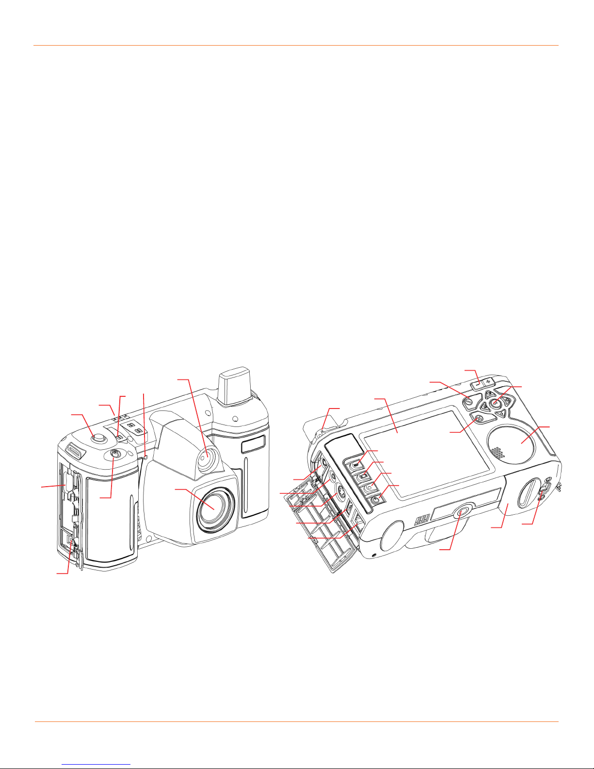
Overview of the TANDBERG FieldView
Device
The TANDBERG FieldView Device provides a mobile videoconferencing
platform. High quality video and audio from a remote site can instantly be
shared with a user in another location. The TANDBERG FieldView Device is
a small, handheld device that can be operated over a wireless network for
maximum mobility. The following illustrations provide an overview of the
features.
5
1
3
8
2
9
1 – Streaming on/off
2 – Still image capture
3 – LED indicators
4 - Microphone
5 – Streaming indicator (red =
streaming/recording on)
4
6
7
6 – Light
7 – Camera lens
8 – SD memory card slot
9 – External power connector
10 – Headset connector
11
15
10
12
13
14
11 – Audio line in (plug in
external audio source)
12 – S-Video
13 – USB host interface
14 – Ethernet port
15 – Stylus
16 – Viewfinder
17 – Send button
18 – End button
16
22
23
24
25
19
17
18
27
26
19 – Zoom/Manual focus controls
20 – Navigation pad
21 – Speaker
22 - Focus button
23 – Display mode button
24 – Recording On/Off
25 – Power
26 – Tripod mount
27 – Battery door
28 – Battery lock
28
20
21
D14098.02 June 2008
2
Page 9
Chapter 1
TANDBERG FieldView Administrator Guide
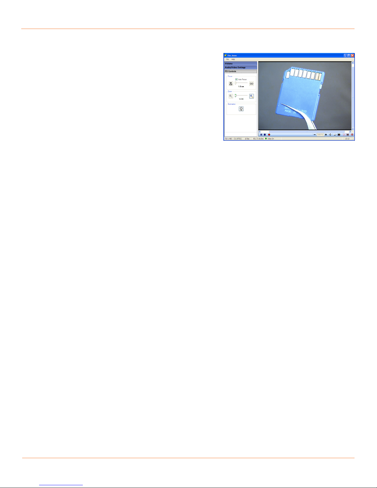
Overview of the TANDBERG FieldView
Application
The TANDBERG FieldView Application forms the communication partner
for the TANDBERG FieldView Device. Operating on a standard Microsoft
Windows workstation, the TANDBERG FieldView Application allows
users to collaborate with, monitor, and control the TANDBERG FieldView
Device.
Note: This document uses the terms PC, laptop, and workstation
interchangeably to refer to a Windows® based personal computer.
For additional information on the TANDBERG FieldView Application,
please see the TANDBERG FieldView Application User Manual.
TANDBERG FieldView Application Call Window
Overview of the FMS
The FMS is an application that assists the administrator with the maintenance
of the FieldView. It permits centralized monitoring of endpoint status as well as
providing a method to deploy common configurations, contact lists and remote
software updates. For more information on the FMS, consult the FieldView
Management Suite User Manual.
Overview of the FES
The FieldView Enterprise Suite provides a cost-effective licensing model for
the deployment of a large number of TANDBERG FieldView Application clients.
It permits users within an enterprise to share from a pool of available calling
licenses. For more information on the FES, consult the FieldView Enterprise
Suite User Guide.
D14098.02 June 2008
3
Page 10

Chapter 2
TANDBERG FieldView Administrator Guide
2. Installation
TANDBERG FieldView Device Installation
Power
The TANDBERG FieldView Device can be powered from an internal replaceable
battery or from AC power via an external power adaptor.
Battery Specifications
Part Number: 100229
Type: Lithium-Ion
Voltage: 7.2 VDC
Capacity: 2400 mAh
CAUTION
Risk of explosion if battery is replaced with an incorrect type.
Warnings
Do not remove the battery while the TANDBERG FieldView Device is •
operational as this may damage the TANDBERG FieldView Device. The
TANDBERG FieldView Device will attempt to shut down immediately if it
detects that the battery door has been opened.
Replace battery only with the same type as recommended by the •
manufacturer.
Dispose of used batteries according to the manufacturer’s product •
documentation and local disposal requirements.
Use only TANDBERG-supplied batteries with the TANDBERG FieldView •
Device. Use of other types may increase the risk of fire or explosion or
damage to the equipment.
Do not store the battery in places where metallic objects may come in •
contact with the battery terminals (e.g. in a pocket with keys, in a drawer
with paper clips, etc.). The resulting short-circuit can cause extremely high
temperatures that may damage the battery and cause burns or fires.
Do not attempt to disassemble the battery. The battery poses a burn hazard •
if handled improperly.
Immediately dispose of a damaged or leaking battery.•
Do not store or leave the TANDBERG FieldView Device or TANDBERG •
FieldView Device battery near a heat source (e.g. radiator, stove, heater,
automobile dashboard, etc.) as the battery may explode or ignite.
Battery Disposal
The TANDBERG FieldView Device uses a Lithium-Ion battery which must be •
disposed of properly.
The battery must not be disposed with household or office waste.•
Do not dispose of the battery in a fire as the battery may explode.•
Contact your local waste disposal agency for the address of the nearest •
battery disposal location.
D14098.02 June 2008
4
Page 11

Chapter 2
TANDBERG FieldView Administrator Guide
External Power Adaptor
The TANDBERG FieldView Device External Power Adaptor permits long term
operation without replacing batteries and will charge the battery that is
installed in the TANDBERG FieldView Device.
Input: 100–240 VAC @ 50/60 Hz (0.6A)
Output: +12 VDC @ 1.5A
Notes:
The TANDBERG FieldView Device requires that a battery be installed at •
all times when operating even if external power is available. This ensures
that the TANDBERG FieldView Device can safely shut down its internal file
system in the event of an unexpected loss of external power.
Software updates require external power to be applied to prevent potential •
problems caused by discharged batteries.
TANDBERG FieldView Device Input/Output
Interfaces
The TANDBERG FieldView Device features the following external
interfaces:
Headset Connector•
External S-Video Connector•
External Audio Input Connector•
Ethernet Connector•
Wireless Local Area Network (WLAN) •
SD slot•
Universal Serial Bus (USB) Host Connector•
Cradle contacts•
More information on these connectors and interfaces is provided in the
following sections.
Headset Connector. The headset connector accepts a standard 3.5 mm
3-wire headset plug.
S-Video Connector. A standard S-Video connector to connect to the video
source. Users can select either the internal video camera or an external video
source from an TANDBERG FieldView Device configuration screen.
External Audio Input Connector. The external audio input accepts a linelevel audio signal on a standard 2.5 mm plug. It can be used to provide subject
audio that will be synchronized and then streamed and/or recorded with the
video.
The audio level from a non-amplified microphone is too low to connect directly
to the audio input. Use an external microphone pre-amplifier to increase the
level to the required nominal 1 Vrms level.
Ethernet Interface. The 10/100Base-T network interface accepts a standard
RJ-45 Ethernet plug. The interface autosenses speed and duplex. The
TANDBERG FieldView Device is a Terminal device and must be connected to a
hub or switch.
Wireless Network Interface. The TANDBERG FieldView Device contains an
integrated IEEE 802.11b/g wireless network interface. The interface has the
following technical specifications:
Frequency band
B Mode: 2.400 – 2.497 GHz (Ch 1 – 14)
G Mode: 2.400 – 2.4836 GHz (Ch 1 – 13)
D14098.02 June 2008
5
Page 12

Chapter 2
Channel Spacing
B/G Mode: 5MHz
Modulation
B Mode: DSSS with DBPSK, DQPSK, and CCK
G Mode: OFDM with BPSK, QPSK, QAM, and 64 QAM, DSSS with
DBPSK, DQPSK, and CCK
Radio Power
B Mode: 13±1 dBm at 1, 2, 5.5, and 11 Mbps
G Mode: 12.5±1.5 dBm at 6, 9, 12, 18, 24, 36, 48 and 54 Mbps
Radio Sensitivity
G Mode: –82 dBm at 6 Mbps
–81 dBm at 9 Mbps
–79 dBm at 12 Mbps
–77 dBm at 18 Mbps
–74 dBm at 24 Mbps
–70 dBm at 36 Mbps
–66 dBm at 48 Mbps
–65 dBm at 54 Mbps
B Mode: –89 dBm at 1 Mbps
–86 dBm at 2 Mbps
–85 dBm at 5.5 Mbps
–82 dBm at 11 Mbps
TANDBERG FieldView Administrator Guide
D14098.02 June 2008
6
Page 13

Chapter 2
Secure Digital (SD) Slot. The SD slot holds an SD card that is used for
storing recordings, as well as performing configuration and software updates.
SD memory cards used with the TANDBERG FieldView Device must provide
sufficient performance in order to record audio/video streams. Suitable SD
cards are typically labeled as High Performance or High Speed but must meet
the following performance specifications:
Minimum write speed ! 9.0 MB/sec•
Minimum read speed ! 10.0 MB/sec•
Notes:
The SanDisk Ultra-II series of SD and SDHC cards have been tested with the •
TANDBERG FieldView Device and are recommended, although other brands
that meet the technical performance specifications should also be acceptable.
SD cards should be formatted using the TANDBERG FieldView Device. •
See the section SD Format. Cards formatted using other programs (e.g.
Windows XP format, etc.) may provide degraded performance.
Universal Serial Bus (USB) Host. A USB host interface is provided for future
growth.
Cradle Contacts. The contacts on the bottom of the TANDBERG FieldView
Device are provided for future growth to support a docking cradle.
TANDBERG FieldView Administrator Guide
Accessories
External Battery Charger. The external battery charger charges and
conditions TANDBERG FieldView Device batteries. Please refer to the
TANDBERG FieldView Device External Charger User Manual for operating
instructions and specifications.
Lens Accessories. The TANDBERG FieldView Device lens provides a standard
30.5 mm threaded connector for the addition of lens filters or other optical
accessories. Use care when adding a lens accessory to avoid stripping the
threads. Do not over tighten.
TANDBERG FieldView Application Installation
The TANDBERG FieldView Application software is meant to be installed on a
workstation (PC) with the following minimum requirements:
Operating System: Microsoft Windows Vista, Windows XP (Service Pack 2 or
later), or Windows 2000 (Service Pack 4 or later)
Processor speed: 1 GHz (1.5 GHz recommended)
Disk space: Up to 120 MB required if Microsoft DirectX, Microsoft .NET
Framework and Visual C++ runtime components are not
already installed
Network: A wired 10/100 Ethernet port is recommended. Some
wireless network adapters may not be optimized for voice
and video operation.
Video card: DirectX v9.0c compatible video graphics card
Audio support: For voice and audio support, the host computer must have
a microphone and speakers and/or headset and/or USB
speakerphone
D14098.02 June 2008
7
Page 14

Chapter 2
TANDBERG FieldView Administrator Guide
First Steps Before Installation
We recommend that the manufacturer’s latest audio, video, and networking drivers
be installed on the host workstation before installing the TANDBERG FieldView
Application software. Refer to the workstation documentation for information on how
to locate and install the necessary drivers.
Installing the TANDBERG FieldView Application Software
Note: Installation of the Enterprise version of the TANDBERG FieldView Application
software using the FieldView Enterprise Suite is similar to the following but utilizes a
customized network or CD-based setup program. Consult the FieldView Enterprise
Suite User Manual for more information.
To install the software:
Sign into the PC as an administrator (either administrator or as a user that is a 1.
member of the administrators group).
If you have previously installed the TANDBERG FieldView Application and it 2.
is currently running, quit the TANDBERG FieldView Application. Also, if the
TANDBERG FieldView Application icon in the Windows Notification Area (next to
the clock) is present, right-click on the icon and select Exit.
Insert the CD into the computer. The installation process should start on its own. If 3.
it does not:
Click the a. Start button on your Windows desktop, and select Run... to open
the Run dialog box.
Type b. D:\FA\setup.exe and click OK to start the installation. Use a drive
letter that matches your CD drive.
Note: always execute setup.exe rather than the .msi file or the installation
may be incomplete.
Follow the installation prompts. The installation puts icons on your desktop for the 4.
TANDBERG FieldView Application and Image Annotator applications and an option
into your Start > All Programs menu.
Depending on what has previously been installed on your computer, first time setup
may prompt you to install a number of utilities, such as the Microsoft .NET Framework
and Microsoft DirectX. Follow the prompts as they appear and re-start the computer
as required.
Coexistence with Security Software
In some cases, resident security programs (e.g. firewall and anti-spyware applications
such as antivirus and worm protection) may block operation or communication
functions of the TANDBERG FieldView Application. This usually results in either an
inability to establish a connection or a warning from the security software asking if the
specified program (the TANDBERG FieldView Application) should be allowed to access
the network or other resources.
In general, you should configure these security applications to allow TANDBERG
FieldView Application communications.
Important: Denying access may prevent proper operation of the TANDBERG
FieldView Application.
Note that some enterprise Virtual Private Network (VPN) clients include a firewall
that may need to be configured to allow TANDBERG FieldView Application
communications.
See Firewall and Anti-Spyware Blocking for a list of specific information relating to
security software configuration.
D14098.02 June 2008
8
Page 15

Chapter 2
TANDBERG FieldView Administrator Guide
Removing the TANDBERG FieldView Application
Software
To remove the software:
Sign into the PC as an administrator (either administrator or as a user that 1.
is a member of the administrators group).
Quit the TANDBERG FieldView Application if it is running. Also, if the 2.
TANDBERG FieldView Application icon in the Windows Notification Area
(next to the clock) is present, right-click on the icon and select Exit.
Select 3. Start > Control Panel > Add or Remove Programs.
From the list of currently installed programs, select the TANDBERG 4.
FieldView Application item and click Change/Remove.
Follow the on screen instructions.5.
Note: The following information will be preserved:
Software license key•
Recordings•
Images•
Infrastructure Installation
Installation instructions for infrastructure equipment such as wireless access
points, network equipment, SIP proxy servers, etc. is beyond the scope of this
document. Please consult the appropriate documentation and vendor support
for the necessary information.
D14098.02 June 2008
9
Page 16

Chapter 3
TANDBERG FieldView Administrator Guide
3. FieldView Network Architecture
Network Overview
The FieldView supports both wired and wireless network operation. Typically,
the TANDBERG FieldView Application will be operated on a workstation that
is connected to a wired network while the TANDBERG FieldView Device will
operate wirelessly; however, any combination of wired and wireless is allowed.
This section provides networking information relevant to the FieldView. In
particular, the section Wireless Networking provides background information
that is important to optimize performance in a wireless environment.
FieldView Network Protocols and Port Usage
Table 3-1 summarizes the network protocols and ports used by the FieldView.
Category Protocol Port(s) Notes Detail
SIP
TCP
5
Random
Signaling
SIP
TCP Random
Signaling
Voice RTP 6004–6200
Video RTP 6000/6001
Subject
RTP 6002/6003
Audio
Data RTP
1
Device OS 2.34 (and lower) used random ports. PC Application 2.5.1 (and lower) used random ports.
2
The ports listed in the range 6000-6200 are the first choice when a call is established. If a requested port is in use on the PC,
4
6006
7
Used for calls that do
not use a SIP proxy
server
7
SIP proxy server based
calls
1
Two-way voice PC/Device sends RTP/
2
2
2,6
Status, control, data,
etc.
2,3
PC/Device sends SIP/TCP
pkts out with SRC=x and
DST=5060
PC/Device sends SIP/TCP
pkts out with SRC=x and
DST=5060
UDP pkts out with
SRC=6004-6200 and DST=x
PC/Device sends RTP/
UDP pkts out with
SRC=6000-6001 and DST=x
PC/Device sends RTP/
UDP pkts out with
SRC=6002-6003 and DST=x
PC/Device sends RTP/UDP
pkts out with SRC=6006 and
DST=x
PC/Device receives SIP/TCP
pkts with SRC=5060 and
DST=x
PC/Device receives SIP/TCP
pkts with SRC=5060 and
DST=x
PC/Device receives RTP/
UDP pkts with SRC=x and
DST=6004-6200
PC/Device receives RTP/
UDP pkts with SRC=x and
DST=6000-6001
PC/Device receives RTP/
UDP pkts with SRC=x and
DST=6002-6003
PC/Device receives RTP/
UDP pkts with SRC=x and
DST=6006
the port number will increment (to a limit of 6200) until an available port is located. The Device will not have conflicts and will
use the ports shown.
3
‘x’ is a random port determined during SIP negotiation.
4
Device OS 2.xx used UDP. PC Application 2.x.x used UDP.
5
Optionally configurable as UDP.
6
Device OS 3.76 (and lower) used port 8888. PC Application 3.1.2 (and lower) used port 8888.
7
DST port is 5060, or 5061 if TLS is enabled.
D14098.02 June 2008
10
Page 17

Chapter 3
TANDBERG FieldView Administrator Guide
Wireless Networking
Wireless technology allows the TANDBERG FieldView Device to be used
in places where accessibility would otherwise be difficult. The TANDBERG
FieldView Device has been optimized for reliable, high quality streaming media
within a wireless environment. This allows the TANDBERG FieldView Device to
remain connected in a streaming session while roaming between access points
over a wide coverage area.
Wireless connectivity on the TANDBERG FieldView Device is provided by an
IEEE 802.11b/g Wireless Local Area Network (WLAN) interface. The WLAN
interface is capable of up to 54 Mbps throughput when operated on an 802.11g
network and 11 Mbps when operated on an 802.11b network.
Notes:
This section assumes that the reader is familiar with wireless networking •
fundamentals.
This section provides general information about 802.11 wireless networks •
as used with the FieldView. For specific information (installation,
configuration, etc.) consult your vendor’s documentation.
Wireless configuration and optimization for the workstation (e.g. a laptop •
computer) that is used to host the TANDBERG FieldView Application is
beyond the scope of this document. Consult the appropriate documentation
and support channels for the workstation.
This discussion relates to the operation of the TANDBERG FieldView Device •
in a wireless mode. Similar considerations exist for operation of a wireless
workstation that acts as host for the TANDBERG FieldView Application.
Many of the topics covered in this section are relevant for the workstation
as well as the TANDBERG FieldView Device; however the performance
and characteristics of wireless networking equipment vary widely. For best
results, the workstation should be connected to a wired network connection
whenever practical.
Although using a wired network connection with the workstation is strongly •
recommended, some wireless workstations will function adequately as long
as sufficient signal quality is available and roaming of the workstation is not
required.
Overview
It is beyond the scope of this document to completely cover all aspects of
wireless networking. However, the following sections provide an overview
of some of the key concepts that relate to the use of voice and video over a
wireless network including the following topics:
Radio Frequency (RF) channel selection•
Interference•
Coverage•
Roaming•
Site survey•
Perspective—Is all this really necessary?
The guidelines in the following sections assure the best possible performance
and quality. However, not every organization will have the means or desire to
ensure that all of the recommended steps are taken. In many cases, a less
rigorous approach may allow acceptable performance as long as the limitations
are understood.
A simple setup (such as connecting to existing infrastructure as-is) will
D14098.02 June 2008
11
Page 18

Chapter 3
often work acceptably if 100% coverage in not mandatory, roaming is not
required, and the wireless network is lightly used. Since good signal quality is
a requirement for good performance, ensuring close proximity to the access
point may overcome limitations caused by violations of the guidelines in this
document. As the demand for quality, coverage and availability increase, the
measures discussed in the following sections should be considered.
If the quality is unacceptable, consider using wired connectivity or making
improvements to the wireless infrastructure.
TANDBERG FieldView Administrator Guide
The Importance of Proper Infrastructure
When implementing a wireless network for voice and video, it is important to
understand the capabilities and limitations that are present in this technology.
The demands of video can be supported; however the infrastructure must be
carefully planned and implemented to achieve the desired performance.
Wireless networks are widely used today, and although they may provide
acceptable performance to users running business transactions or surfing
the web, they may not be adequate for streaming real time media. Voice and
video represent a continuous data stream and can exhibit noticeable visual
or audible artifacts with losses or delays in data delivery. Guaranteeing low
loss and delay is difficult given that the basis of WLAN is radio, a medium
inherently susceptible to effects such as dropout, fade, and interference. But
wireless technology has evolved to make it robust and able to support reliable
communications at rates of up to 54 Mbps, with even faster rates under
development.
To realize the full promise of this technology it must be used within the limits
it was designed for, especially if the payload is voice and video. By following
guidelines aimed at improving and optimizing the radio environment, you can
maximize range and performance, and achieve the best possible use of the
wireless infrastructure.
Special Needs for Voice and Video
Real-time media such as video and particularly voice place more stringent
requirements on the network than conventional data transactions such as
copying files, web browsing, downloading files, etc. In the case of a wireless
network, this is particularly important because improper configuration can lead
to unacceptable performance.
Data protocols are typically fault tolerant. Lost data packets can be recovered
by higher level protocols such as TCP/IP that ensure that every packet is
accounted for. Missing packets are resent. Time is not overly critical and so
recovering missing data can occur in the background without the user noticing.
For example, time to download a file may take a few seconds longer than it
would in a case where the network is not suffering from packet loss.
Conversely, voice and video require real-time delivery. For a real-time media
stream, a late packet is the same as a lost packet. Retry can be used to
recover from lost packets but if the time to do so exceeds tens of milliseconds
then the latency in the voice and video becomes unacceptable to the user.
This is especially significant on wireless networks because, unlike most
wired networks where a lost packet is an unusual event, lost packets are
expected. (Studies show that packet error rates of 5 to 15% are common.)
Minimizing error rate is crucial in order to achieve the best possible streaming
performance.
Fig. 3-1 802.11 b/g Channel Separation
(North America).
D14098.02 June 2008
12
Page 19

Chapter 3
TANDBERG FieldView Administrator Guide
Radio Frequency Channel Selection
The 802.11b/g wireless interface operates in the unlicensed 2.4 GHz frequency
spectrum. Up to 14 channels are allocated within this spectrum. The number
of channels varies with the region (e.g. 11 channels in North America, 13
channels in most of Europe, etc.)
Unfortunately, not all of the channels can be used at a single geographic
location because, while each channel consumes over 22 MHz of bandwidth, the
channels are only separated by 5 MHz. This channel overlap is illustrated in Fig.
3-1.
Overlapping channels cause interference resulting in degradation of quality
and throughput. As shown in the diagram, channels must be separated by a
minimum of five channels to ensure interference does not occur. This limits the
maximum number of channels that can be used in close proximity to three.
In North America, the only option for more than two non-overlapping channels
is to choose channels 1, 6, and 11. In other regions of the world, the additional
available channels allow other choices but the three channel limit still exists.
Notes:
Further complicating channel selection is the possibility that a neighboring •
site may use one or more channels that conflict with the channels in use at
a given location.
Existing infrastructure at some sites violate channel overlap rules without •
realizing it. The network may appear to work fine with data but won’t be
sufficient for real-time media. Network monitoring may show:
•
Degraded signal quality resulting in lower transmission rates.
•
Packet errors resulting in frequent 802.11 retries.
•
Data operations tend to occur in bursts which lower the likelihood for
collisions when compared to voice and video which require a continuous
and regular packet stream.
Robust high level protocols such as TCP/IP mask overlap problems •
because lost packets are automatically recovered. Although performance
degradation occurs, it may not be readily apparent for file transfers,
downloads, etc. because the operations will eventually succeed.
Interference
As discussed above, interference from adjacent channels can cause problems
with wireless performance. Unfortunately, there are other sources of
interference within the unlicensed 2.4 GHz RF band utilized for 802.11b/g
WLAN operation. Interference sources include:
Microwave ovens•
2.4 GHz cordless phones•
Bluetooth devices•
802.11 Frequency Hopping devices•
Other 802.11b/g equipment (APs, client devices) on overlapping or •
improperly separated channels
A variety of other 2.4 GHz equipment•
Where possible, interference sources should be minimized. If that is not
possible, other strategies such as channel remapping or relocation may
be considered. A site survey (as discussed in Site Survey) is useful in
understanding and resolving interference issues.
D14098.02 June 2008
13
Page 20
Chapter 3
TANDBERG FieldView Administrator Guide
Wireless Coverage
Range achievable over the 802.11b/g WLAN interface can vary from hundreds
of meters under near ideal conditions down to much shorter distances under
challenging conditions. Coverage area can vary dramatically depending on a
variety of factors, including:
Topography•
•
Walls, dividers, windows, ceilings, floors, etc.
•
Radio-reflective materials (may cause attenuation and/or multi-path
reflections)
Interference and noise•
Access point and antenna mounting location•
Antenna type and orientation•
TANDBERG FieldView Device orientation•
Network traffic•
Number of connected devices•
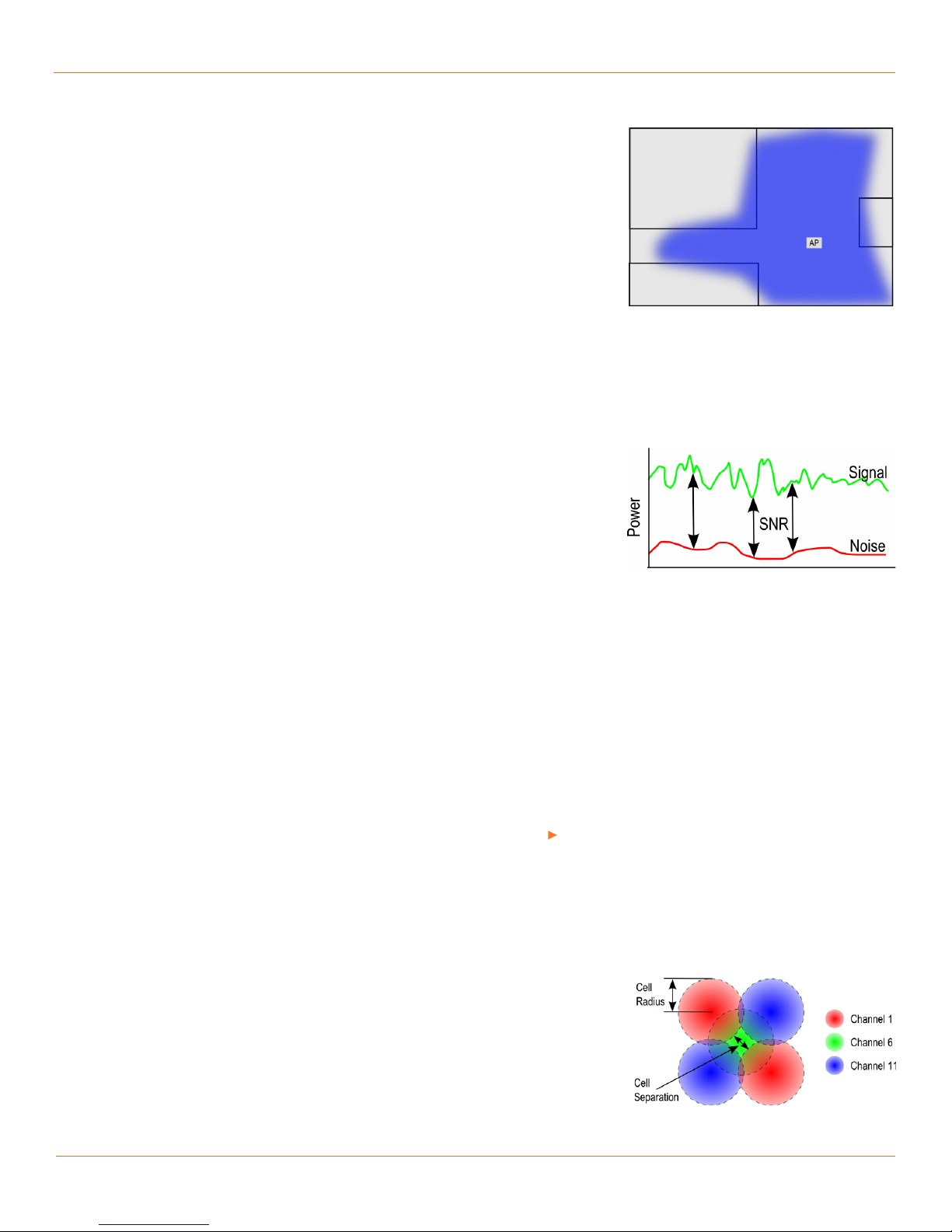
Effect of Topography on Coverage
Fig. 3-2 shows an aerial view of a simple floor plan with a single access point
(denoted as AP). The dark blue shaded area indicates the coverage pattern
that the access point provides for this site. The building’s walls and dividers act
as attenuators for the signal, shaping the coverage pattern as shown.
Fig. 3-2 Wireless Coverage Map (Aerial
View).
Signal to Noise Ratio
Achievable range is directly related to the quality of the signal received by
the TANDBERG FieldView Device. The quality is a factor of the radio signal
strength, which is affected by attenuators such as the topographic features
listed above and the air itself, and the interference and noise level.
As the noise level approaches the level of the desired received signal, the
quality will suffer. To increase usable range, noise must be kept to a minimum
and signal strength must be used to overcome the remaining noise level (there
is always some level of background noise). The usual measure of signal quality
is Signal-to–Noise Ratio (SNR) which is illustrated in Fig. 3-3 with a simplified
signal.
The TANDBERG FieldView Device provides received signal strength and
SNR information that can be used to assist with range determination and
troubleshoot problems. A more rigorous method of ensuring proper coverage
across a facility is done using a site survey, as discussed in the section Site
Survey.
Other Factors Affecting Coverage
Range further depends on the configuration of the video and audio settings. In
general, higher bit rate settings will lower the range achieved before noticeable
artifacts occur.
In practice, range will vary widely with the factors discussed. The TANDBERG
FieldView Device has been tested and found to work satisfactorily at a distance
of over 200 meters with a 1 Mbps video stream under near-ideal conditions
(outdoors, line of sight, no obstructions, access point mounted at 8 feet, no
nearby 2.4 GHz interference sources). At the other extreme, combinations of
interference and topographic factors can limit range to a fraction of the ideal.
Coverage problems can usually be resolved by assuring proper access point
placement and/or adding additional access points.
Fig. 3-3 Signal to Noise Ratio (SNR).
Fig. 3-4 Wireless Cell Layout.
D14098.02 June 2008
14
Page 21

Chapter 3
TANDBERG FieldView Administrator Guide
Wireless Coverage of Large Areas
Coverage of large areas requires multiple access points to ensure that all areas
receive an adequate signal. Taking into account the channel selection process
outlined earlier, the access points should be mapped to not interfere with each
other. An illustration of an ideal case of this is shown in Fig. 3-4.
Each cell represents the idealized coverage area of an individual access point.
Signal strength is highest near the center of the cell and fades near the edges.
As mentioned, obstructions and other factors will cause the actual shape
of the cells to vary widely. The key to proper cell layout is to ensure that
adjacent cells use channels that don’t interfere and that enough cell separation
is maintained between cells on the same channels so that interference is
minimized.
Cell radius is measured in signal strength or signal quality rather than distance.
For high quality audio and video streaming, a cell radius of –67 dBm to
–70 dBm is recommended. Same channel cell separation should be 18 to 20 dB.
Ensuring these guidelines are met will allow the TANDBERG FieldView Device
to maintain an audio/video connection while roaming from cell to cell within a
facility.
Notes:
Keep in mind that cells may be organized in three dimensional space due to •
access points on floors above or below.
Consider that access points may be in use in adjacent facilities.•
A site survey (as discussed in the section • Site Survey) is necessary to
ensure optimal cell mapping.
Capacity
Capacity (number of simultaneous calls) depends on many factors, including
infrastructure type, other traffic, stream settings, error rate, etc. Consult your
infrastructure partner for assistance in determining available capacity.
Improving Performance
In addition to the guidelines covered elsewhere, the following items may
improve overall performance and capacity:
A mixed 802.11b/g network requires that a portion of every packet will be •
sent at a slow rate to maintain compatibility with older 802.11b devices.
By switching the network to 802.11g only, overall bandwidth utilization will
become more efficient but at the cost of not allowing 802.11b devices to
share the network.
Many enterprise quality access points provide quality of service features •
that give priority to real time packets such as voice and video. These
features should be enabled when available.
Consider using directional access point antennas for focused coverage of •
long narrow areas.
Performance for simultaneous use of many wireless devices in a small •
area can be optimized by reducing the cell size. This is usually done by
increasing the number of access points in an area while reducing the output
power of each to minimize overlap.
Configure radio equipment to use short preambles since most equipment •
supports its use. Unless very old legacy equipment must be supported,
short preambles can be used to improve bandwidth efficiency.
Roaming performance can be improved on the TANDBERG FieldView Device •
D14098.02 June 2008
15
Page 22

Chapter 3
by enabling only the RF channels that are in use at the site in the RF
channels configuration screen. The TANDBERG FieldView Device determines
which access points are available for roaming by sampling each channel.
This process takes time and requires the TANDBERG FieldView Device to
stop sending and receiving the media stream. The time lost during this
process can be reduced by scanning only the channels in use at the site.
See the section Network>Radio for information on how to configure this
feature.
TANDBERG FieldView Administrator Guide
Site Survey
Regardless of whether the wireless network at the site is new or existing,
the best assurance that it will be suitable for high-quality voice and video
streaming is to perform a site survey. This involves evaluating the coverage
area of factors such as:
Examining existing WLAN usage•
Signal quality•
Interference and noise•
Channel assignment•
Device location•
Site topography•
The goal is to ensure mobile operation without significant loss of quality over
the desired coverage area mainly by providing:
Adequate bandwidth•
Data transmission reliability•
Low latency/delay time•
It is best to use an experienced WLAN site survey contractor for complex
installations. This is usually available as a service from enterprise WLAN
infrastructure suppliers.
Wireless Security
Wireless networks should be operated with appropriate security measures.
Consult your site administrator for requirements and necessary access key.
See the section Wireless Network Properties for information on configuring the
TANDBERG FieldView Device to support specific security modes.
Wireless Troubleshooting
Please refer to chapter 9. Troubleshooting and your site’s WLAN infrastructure
troubleshooting guide for troubleshooting assistance.
Firewalls and Network Address Translation
Firewalls and Network Address Translation (NAT) can conflict with successful
operation of the FieldView. While in some cases it may be possible to open the
firewall or NAT to directly allow FieldView traffic, this may be cumbersome and
is not recommended due to the security risks.
Instead, use a secure SIP firewall traversal system. Consult TANDBERG for
assistance and recommendations with firewall and Network Address Translation
(NAT) traversal issues.
D14098.02 June 2008
16
Page 23

Chapter 4
TANDBERG FieldView Administrator Guide
4. TANDBERG FieldView Device
Configuration
Manual Focus
Quick Setup for Basic Wireless Operation
This section provides a quick description of how to initially configure the
TANDBERG FieldView Device for a wireless network. Configuring for wired
Ethernet operation is similar.
Preparation
In preparation, ensure the wireless infrastructure (access points) is operating
and available. Identify the configured channel, SSID, and security parameters.
Follow the instructions in the TANDBERG FieldView Device Quick Start Guide to
install and charge the battery. This may take up to eight hours if fully depleted.
Configuration
To start and login to the TANDBERG FieldView Device:
Press the 1. Power button to turn on the TANDBERG FieldView Device. When
the power is on, the Power indicator LED is green.
Login using the default account (User Name: 2. admin, Password: admin)
or select Skip if Anonymous Login is configured for this device (This is the
default).
Note: This quick setup assumes that the initial default admin user and
password has not been altered. If unable to successfully login to the device,
consult your site administrator for the appropriate login information.
Display Mode
Record
Power
Fig. 4-1 TANDBERG FieldView Device control
buttons.
Power
Fig. 4-2 TANDBERG FieldView Device
indicators.
Network available
Charging
To open the Configuration window:
Repeatedly press the 1. Display Mode button until the Main Menu appears
(see Fig.s 4-1 and 4-3).
If the Status Menu appears (Fig. 4-4) instead of the Main Menu, tap the 2.
Back to Main Menu option.
On the Main Menu, tap the 3. Configuration option. The Configuration
window appears.
To configure the radio:
In the Configuration window, use the navigation pane on the left-hand side 1.
of the window to select the Network>Radio page.
Fig. 4-5 Radio Configuration page
Fig. 4-3 Main menu.
Fig. 4-4 Status menu.
D14098.02 June 2008
17
Page 24
Chapter 4
TANDBERG FieldView Administrator Guide
Verify that the radio is enabled (2. Enable Radio checkbox is selected).
3. Tap Apply.
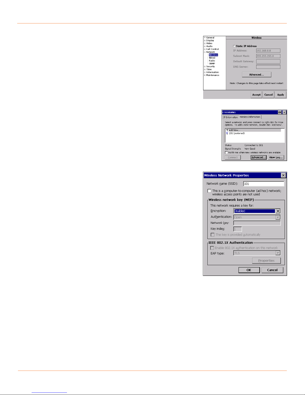
To configure wireless connectivity:
In the Configuration window, use the navigation pane on the left-hand side 1.
of the window to select the Network>Wireless page (Fig. 4-6). Note that
any changes to this page require a device restart before they take effect.
Note: The IP address shown in Fig. 4-6 is grayed out and is only available to
edit when the Static IP Address option is checked. This does not mean that
the TANDBERG FieldView Device is presently using the IP address shown.
Tap 2. Advanced… in the Wireless configuration area. The CF8385PN1
window appears.
Tap the 3. Wireless Information tab (see Fig. 4-7). After a few seconds the
TANDBERG FieldView Device will display a list of SSIDs for nearby wireless
networks. In this example, the list contains a single network that has an
SSID of 101.
Note: Only access points configured to broadcast their SSID will be displayed.
Connection to networks that do not broadcast their SSID requires a new entry
to be created as described in the section Wireless Network Properties.
Fig. 4-6 Network Configuration tab.
Tap the desired network to highlight it and then tap the 4. Connect button.
If this network has not been configured before, the Wireless Network
Properties window appears (see Fig. 4-8). If the keyboard is in the way,
you can move it by touching the top of the keyboard with the stylus and
dragging it.
Note: If the SSID has (preferred) beside it, it has already been configured.
If the network properties need to be changed, tap the SSID twice (similar
to double-clicking a mouse button) to open the Wireless Network Properties
window.
Enter the wireless network properties to match the settings of your access 5.
point. For more information, see the section Call Control.
Select 6. OK to accept the properties and return back to the CF8385PN1
window. The settings are saved to flash and kept permanently.
In the CF8385PN1 window (Fig. 4-7) watch the status displayed below 7.
the network list. Wait a few seconds for the connection to establish.
If successful, the Network LED (middle LED on top of the TANDBERG
FieldView Device) will be green and the status will display:
Status: Connected
Signal Strength: Good, Very Good, or Excellent
Fig. 4-7 Wireless Information.
Fig. 4-8 Wireless Network Properties.
D14098.02 June 2008
18
Page 25
Chapter 4
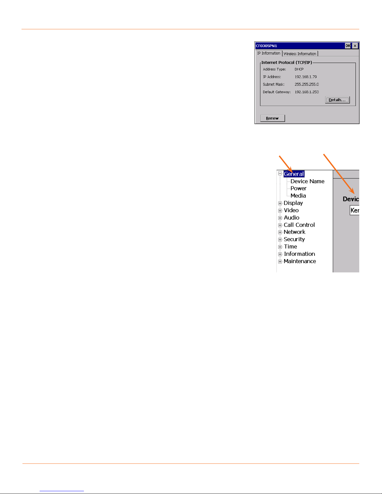
To view the TANDBERG FieldView Device’s IP information:
• Select the IP Information tab (see Fig. 4-9) in the CF8385PN1 window.
Note: You can also view the TANDBERG FieldView Device IP address from the
Status Menu > Network Status.
If your network uses Dynamic Host Configuration Protocol (DHCP), your
TANDBERG FieldView Device will have acquired an IP address from your DHCP
server. Otherwise you can set a static IP address as explained in the following
procedure.
If the TANDBERG FieldView Device did not acquire an IP address, then review
the instructions in this section.
To configure a static IP address:
In the Configuration Window, select the Network page (Fig. 4-6).1.
In the Wireless configuration area, check 2. Static IP Address.
The Static IP Address fields become active. Note that changes to this page
require a device restart before they take effect.
Complete the 3. IP Address, Subnet Mask, Default Gateway, and DNS
Server fields.
Continue to configure the wireless connectivity as explained in the previous 4.
procedure.
Power cycle the device to have your changes take effect.5.
TANDBERG FieldView Administrator Guide
Fig. 4-9 IP Information.
Navigation Pane
Configuration Page
Configuration Options
Configure the TANDBERG FieldView Device using the menus displayed in the
viewfinder. You can configure and monitor parameters such as:
Video settings•
Video source•
Standby timeout•
Viewfinder brightness•
Stylus (touch screen) calibration•
Audio gain/volume, ring tones, audio source•
Radio/Ethernet: DHCP/static, SSID, security, channels•
Time and date•
Version information•
Software updates•
Security options•
SIP configuration: URI, registrar•
The TANDBERG FieldView Device Configuration screens are explained on the
following pages.
Accessing the Configuration Window
To open the Configuration Window:
Repeatedly press the 1. Display Mode button (see Fig. 4-1) until the Main
Menu appears.
If the Status Menu appears (Fig. 4-4) instead of the Main Menu, tap the 2.
Back to Main Menu option.
Tap the 3. Configuration option on the Main Menu to display the
Configuration window.
The configuration items are organized into multiple pages. A navigation pane
on the left-hand side of the window can be used to select the desired page.
Fig. 4-10 Navigation pane.
D14098.02 June 2008
19
Page 26

Chapter 4
Use navigation pad or the stylus and the + and – items to show or hide lowerlevel pages in the hierarchy.
TANDBERG FieldView Administrator Guide
Accepting and Canceling Configuration Changes
The Apply button allows changes to be made immediately without exiting the
configuration page. The Accept button accepts all pending changes and exits
the configuration screens. The Cancel button undoes the changes that have
been made and exits the configuration page.
Note that some of the configuration items take effect when you tap either the
Apply or Accept button, while others take effect immediately. For the items
that do not take effect immediately, selecting the Cancel button will exit
the configuration screens and discard the changes. Changes that take effect
immediately cannot be canceled and must be manually undone.
General
General>Device Name
Device Name. The Device Name is used as the Domain Name System (DNS)
name for the TANDBERG FieldView Device and must be unique within a DNS
Domain. The default Device Name is a unique value starting with TANDBERG
FieldView Device followed by the MAC address of the 802.11b/g radio.
The Device Name must be formed according to the following rules:
Length of the name must be from 1 to 15 characters. The name cannot be •
blank.
Name can contain characters from the following three ranges: A-Z, a-z, 0-9.•
Underscore (_) is allowed.•
Dash (-) is allowed.•
Name must start with an alpha character, in upper or lower case.•
• Name cannot end in a dash (-) or underscore (_).
Note: Other punctuation and spaces are not allowed in the name.
Any changes you make to the Device Name will not be applied until you
restart the TANDBERG FieldView Device.
Fig. 4-11 General>Device Name
Configuration Page
Fig. 4-12 General>Power Configuration Page
General>Power
Standby Timeout. If the TANDBERG FieldView Device is not used for the
duration of the Standby Timeout, it will enter Standby mode. The default
period is 2 minutes.
In Standby mode portions of the TANDBERG FieldView Device are powered
down to lower battery drain.
Entering a standby timeout value of 0 disables automatic standby. The
TANDBERG FieldView Device can be placed in standby manually by pressing
the Power button.
Press the Power button to wake the TANDBERG FieldView Device.
Note: Using standby mode prolongs battery life. Specify a short timeout value
so that the TANDBERG FieldView Device will go into standby more promptly
when not in use.
D14098.02 June 2008
20
Page 27

Chapter 4
TANDBERG FieldView Administrator Guide
General>Media
Media Path. Media Path defines the folder on the SD card where the
TANDBERG FieldView Device will store snapshots and recordings. The default
folder is \Storage Card\Media.
If the folder does not exist, the TANDBERG FieldView Device will create the
folder when it starts a new recording. Tap the … button to select or create a
folder using the File Browser.
Note: When viewing the SD card on a PC the \Storage Card prefix will be
replaced by the drive letter associated with the SD card. e.g. F:\Media.
While sharing an image, the video:
Select Continues to allow video to continue while images are shared. The
remote participant can continue to watch and/or record the video while images
are shared.
Select Pauses to pause or “freeze” the video. The remote participant can
continue to watch and/or record the video while images are shared; however,
the image on the video is not updated.
Select Stops to stop the video. The remote participant will no longer be able
to watch or record the video while images are shared. However, the network
bandwidth required for the connection will be reduced.
Fig. 4-13 General>Media Configuration Page
Display
Display>General
Show Actual Video Boundary. For some video resolutions, the content
included in the video stream does not exactly match the boundaries of the
viewfinder display. Items near the edges of the viewfinder may not actually be
included in the video stream. The Show Actual Video Boundary selection
can be used to clarify what the boundaries are regardless of video resolution.
Select • Disabled to show the full viewfinder without regard to the actual
video boundaries of the streamed video content.
Select • Mat to frame the true area of the streamed video content with a
semi-transparent mat.
Select • Rectangle to frame the true area of the stream video content with a
bounding rectangle.
Align Stylus to Screen button. Tap Align Stylus to Screen to calibrate the
alignment of the touch screen and the viewfinder.
Realignment may be required to suit individual user preference, as the device
ages, and after some operating system software updates.
Fig. 4-14 Display>General Configuration
Page
D14098.02 June 2008
21
Page 28

Chapter 4
TANDBERG FieldView Administrator Guide
Display>Backlight
Backlight power save checkbox. Check Backlight power save to set the
backlight to the lowest level to save power.
You can manually set the backlight to its lowest power by holding the Display
Mode button for 2 seconds. Press and hold the Display Mode button a second
time to restore the backlight level to the previous setting.
Viewfinder backlight brightness control. You can choose from four levels
of backlight brightness adjustment.
Video
Video>Color
Brightness/Hue/Saturation/Contrast/Sharpness sliders. Adjust these
sliders to modify the camera module image parameters.
Defaults button. Tap Defaults to restore video brightness, hue, saturation,
contrast and sharpness to the default values.
White Balance. Select the proper white balance for different lighting
conditions.
Auto: Continuous adjustment for lighting conditions from 3000K to 7500K
Indoor: Tungsten lighting
Outdoor: Sunlight
One Push: Manual calibration. Follow the onscreen instructions to calibrate the
white balance using a white reference object.
Auto Tracing: Continuous adjustment for lighting conditions from 2000K to
10000K
Preview Display
The preview display permits monitoring the changes made on the Color page.
Video>Source
Video Source. Choose a video source of either the internal camera module or
an external video source via the S-Video input connector.
When using an external video source, select the appropriate video type.
Usually the video type is NTSC for North American equipment and PAL for
European equipment.
Fig. 4-15 Display>Backlight Configuration Page
Fig. 4-16 Video>Color Configuration Page
D14098.02 June 2008
Fig. 4-17 Video> Source Configuration Page
22
Page 29

Chapter 4
TANDBERG FieldView Administrator Guide
Audio
Audio>General
Subject Audio Source. Select the source of subject audio. It can be either
the built-in microphone or the line-in jack.
Note: Line-in is Line level.
Prefer low bandwidth voice codec. Select to use a lower bit-rate codec for
voice in order to reduce network bandwidth utilization. The 13.5Kbps GSM 6.10
codec will be used instead of the 64Kbps G.711 codec if the remote endpoint
supports its use. Note that this will result in a reduction of voice fidelity.
Prefer low bandwidth subject audio codec. Select to use a lower bit-rate
codec for subject audio in order to reduce network bandwidth utilization. The
13.5Kbps GSM 6.10 codec will be used instead of the 64Kbps G.711 codec if
the remote endpoint supports its use. Note that this will result in a reduction of
subject audio fidelity.
Mute ringer when headset is inserted checkbox. Check to have incoming
calls ring on the headset but not on the loudspeaker. Rings will still play on the
speaker if a headset is not connected.
When this option is unchecked, incoming calls will ring on both the loudspeaker
and on the headset.
Fig. 4-18 Audio>General Configuration Page
Enable voice silence suppression. Check to use voice silence suppression.
Silence suppression reduces the bandwidth utilized for sending voice during
periods of silence. Disabling silence suppression may be useful in some cases
when quiet voice passages are being suppressed. However, silence suppression
should normally be left enabled since it reduces bandwidth utilization and also
helps to reduce voice latency.
Audio>Volumes
Speaker Mute checkbox. Check to turn off the TANDBERG FieldView Device
speaker.
To turn off the TANDBERG FieldView Device speaker manually, set the volume
to zero using the rear panel Volume Down button.
Microphone Mute checkbox. Check to turn off the TANDBERG FieldView
Device microphone. When the microphone is muted, voice and audio will no
longer be streamed or recorded.
To turn off the TANDBERG FieldView Device microphone manually, press the
rear panel Mute button.
Fig. 4-19 Audio>Volumes Configuration Page
D14098.02 June 2008
23
Page 30

Chapter 4
Speaker Volume. Adjust the slider to set the speaker volume.
To set the speaker volume manually, use the rear panel Volume Up and Down
buttons.
Ring Volume Maximum. Adjust the slider to set the maximum volume for
the ring sound.
When the TANDBERG FieldView Device rings, it starts at a low volume and
increases up to the value of this control.
TANDBERG FieldView Administrator Guide
Call Control
Call Control>General
Enable auto answer. Check to enable incoming calls to be automatically
answered. This capability can be disabled by users with administrative
privileges.
Allow anyone to enable/disable auto answer (Admin only). Check if
non-administrative privileged users are allowed to enable or disable the auto
answer capability. This checkbox does not appear for non-administrative users.
Call History Maximum. Specify the number of calls to maintain in the call
history accessed using the rear Send button.
Note: The call history can be cleared using the Maintenance> Call History
page. See section Maintenance > Call History.
Call Control>SIP
If you will be using a SIP registrar to call between your TANDBERG FieldView
Application and TANDBERG FieldView Devices, configure the SIP account
information here. Refer to Appendix C for more information on configuring
SIP.
You have the choice of giving the device itself a SIP account or assigning a SIP
account to each user.
If you choose to assign each device its own SIP account, enter the information
here and under SIP Settings. However, if you are assigning SIP accounts
for each TANDBERG FieldView Device user, then select Always use my SIP
settings. SIP settings for each user are saved in the LocalRegistrationService
file. See chapter 7. User and Contact Management and Distribution for additional
information on configuring TANDBERG FieldView Device users.
Fig. 4-20 Call Control>General Configuration
Page
Enable SIP Registration. Uncheck if SIP registrar is not used.
Always use my SIP settings. When selected, the user’s SIP information
is used instead of the Device Settings as configured on the Call Control>SIP
Settings page.
Use UDP instead of TCP for SIP messaging. Select to specify UDP rather
than TCP for SIP messaging for direct IP-to-IP calls (i.e. not via a SIP proxy).
Select UDP if the destination endpoint does not support TCP.
D14098.02 June 2008
Fig. 4-21 Call Control>SIP Configuration Page
24
Page 31

Chapter 4
TANDBERG FieldView Administrator Guide
Call Control>SIP Settings
Use the Device Settings radio button to edit or display the device SIP
configuration. Use the My Settings radio button to display the current user’s
SIP configuration.
SIP Information
Values entered here are based on account information from your SIP registrar.
Table 4-1 SIP information
Field Description Example
URI Universal resource
identifier
SIP Server
Address
Authentication
User Name
Authentication
Password
Authentication
Type
Authentication
Transport
Address of SIP server mainsrv.xyz.com
User name of SIP
server account
Password of SIP server
account
Select Digest or none
Select TCP or TLS as
appropriate for the SIP
registrar
mydevice@sipsrv.xyz.com
jsmith108
*******
Fig. 4-22 Call Control>SIP Settings
Configuration Page
Network
Network>Wireless
Static IP Address. Check Static IP Address to define a static set of IP settings
for the wireless radio connection.
You must restart the TANDBERG FieldView Device for changes in this window
to take effect.
Note: Grey entries are disabled and are ignored.
Advanced… Tap Advanced to open the advanced wireless networking
configuration.
Fig. 4-23 Network>Wireless Page
D14098.02 June 2008
25
Page 32

Chapter 4
TANDBERG FieldView Administrator Guide
CF8385PN1 – Wireless Information
Any wireless networks in the vicinity that broadcast their SSID are listed
here. Only wireless networks operating on the radio channels selected under
Configuration > Radio are scanned.
If a network is not broadcasting its SSID, the network name will not appear in
the list. Double-tap Add New… to manually create a network entry.
Status and Signal Strength. Status and signal strength are shown for the
active or selected network. The possible values are:
Status:
Not Connected•
Scanning•
Associating•
Associated•
Connected•
Signal Strength:
No Signal•
Poor•
Good•
Very Good•
Excellent•
Double-tap a network entry to view the network’s Wireless Network Properties.
Fig. 4-24 Wireless Information
Wireless Network Properties
Network name (SSID). Network name (SSID) is the SSID of the wireless
network which you are configuring. Many network configurations can be
created and saved on the TANDBERG FieldView Device. See also section
Advanced Wireless Settings.
This network name must match the SSID used by the Access Points of the
network.
This is a computer-to-computer (ad hoc) network. This field is not
currently supported and must not be selected.
Encryption. The following encryption options are supported: Disabled, TKIP,
WEP (40 and 128 bit), AES.
Authentication. The following authentication options are supported: Open,
Shared, WPA, WPA2, WPA2-PSK, WPA-PSK.
Network Key. The Network Key is used with WEP encryption and WPA-PSK
and WPA2-PSK authentication options.
WEP 128 requires 26 hex digits and WEP 64 requires 10 hex digits. An ASCII
network key may be used if the encryption is TKIP.
Key Index. The Key Index is used with the WEP authentication option. The
allowed values are 1 to 4.
This key is provided automatically. Uncheck this option if you want to enter
a WEP key.
Fig. 4-25 Wireless Network Properties
Enable 802.1X authentication on this network. Check to enable 802.1X
authentication using one of the supported EAP types.
EAP Type. Select an EAP type to be used with 802.1X authentication. The
choices are PEAP or EAP-TLS. Tap Properties to view the authentication
settings. See Fig. 4-26.
If you choose TLS, you must select a security certificate from those installed in
D14098.02 June 2008
Fig. 4-26 Authentication Settings
26
Page 33

Chapter 4
TANDBERG FieldView Administrator Guide
the My Certificates store. (For more information about loading certificates onto
the TANDBERG FieldView Device, see Security) The User Information User
Name must match the certificate you have selected.
Check Validate Server if you have imported the root certificate of the
authority which signed the server’s certificate. The TANDBERG FieldView
Device uses this root certificate to verify the server’s identity.
Tap Select to view the certificates. See Fig. 4-27. Certificate details are
available by tapping View Certificate. See Fig. 4-28.
Advanced Wireless Settings
Use Windows to configure my wireless settings. Windows is used to
configure wireless settings. This checkbox must be selected.
Preferred Networks. The Preferred Network list displays networks that
have been used in previous connections. The connection properties for these
networks have been saved. The order of the networks in the list indicates the
order of preference.
To remove an unused network or to clear a network’s configuration so it can be
re-entered, select the network and tap Delete.
Automatically connect to non-preferred networks. Check to have the
TANDBERG FieldView Device attempt to connect to any available network; not
just networks listed in the preferred network list.
The default state is unchecked.
Networks to access. Select the category of networks for the TANDBERG
FieldView Device to access. The options are:
All available (default)•
Only access points •
Only computer-to-computer (Do not use. Not currently supported.)•
CF8385PN1—IP Information
Renew. If DHCP is being used, tap Renew to update the IP information from
the DHCP server.
Details… Tap Details… to display additional IP information.
Only the first two DNS servers are listed in the detailed IP information. For a
complete list of DNS servers, open the Network Status screen from the Status
menu.
Fig. 4-27 Select a Certificate
Fig. 4-28 Certificate Properties
Fig. 4-30 Wireless IP Information Fig. 4-31 Detailed IP Information
D14098.02 June 2008
Fig. 4-29 Advanced Wireless Settings
27
Page 34

Chapter 4
TANDBERG FieldView Administrator Guide
Network>Radio
Enable Radio. Select to enable the radio. When disabled, wireless network
communication is not available. When wireless networking is not required,
disable the radio to save power.
Allow anyone to enable/disable radio (Admin only). Check if nonadministrative users are allowed to enable or disable the radio. This checkbox
does not appear for non-administrative users
Scan all available channels. Check to automatically scan all channels.
Customize scan channels. Select the 802.11b/g radio channels which will
be scanned. These should match the access points you will be operating with.
Access points operating on other channels will not be scanned.
In France the permitted channels are only in the range of 1 to 7 when
operating outdoors.
Note: Limiting the channels that are selected will improve roaming
performance by speeding switching and reducing the possibility of dropouts. If
you don’t know which channels are in use at a given site, enable all channels.
Network>SNMP
The SNMP configuration screens allows configuration of the TANDBERG
FieldView Device to be managed by the FieldView FieldView Management Suite
(FMS). Consult the FMS User Manual for information on configuring these
settings.
Fig. 4-32 Network>Radio Configuration
Page
Security
Security>Login
The options in this window configure the User Authentication window. The User
Authentication window appears:
When the TANDBERG FieldView Device powers up•
After a user logs out•
When resuming from standby (if enabled)•
Auto Login
If an TANDBERG FieldView Device is dedicated to an individual, their Username
and Password can be entered here to speed up login.
See Chapter 7. User and Contact Management and Distribution for information on
creating Local User accounts
Service: None=request manual entry of Username/Password
Local=use Username/Password shown
Username: Username of individual. Must exist in LocalRegistrationService.
xml.
Password: Password of individual. Must exist in LocalRegistrationService.xml.
Fig. 4-33 Security>Login Configuration Page
D14098.02 June 2008
28
Page 35

Chapter 4
TANDBERG FieldView Administrator Guide
Anonymous login permitted. Check to display a Skip button on the User
Authentication window so that the login can be bypassed. The user is named
‘anonymous’ in this case.
Force login when resuming from Standby. Check to open the User
Authentication window whenever the TANDBERG FieldView Device wakes from
Standby.
Security>Certificates
Certificates button. Tap Certificates (see Fig. 4-34) to open the Certificates
window to view and import security certificates.
Note that when using certificates the TANDBERG FieldView Device date and
time must be current to allow successful verification of the certificate.
See the section Wireless Network Properties for more information.
Import… button. Tap the Import… button in the Certificates window to
import certificate files (to the selected Store) from an SD card for use with
network authentication (see Fig. 4-35).
The TANDBERG FieldView Device searches the storage card root (\Storage
Card\) and a top-level Certificates directory for compatible files (\Storage
Card\Certificates\). You must confirm the import. See Fig. 4-36 and Fig. 4-37.
Fig. 4-34 Security>Certificates Page
Fig. 4-35 Certificates window
Note: When viewing the SD card on a PC the \Storage Card prefix will be
replaced by the drive letter associated with the SD card. e.g. F:\Certificates.
File types allowed for import are:
• Certificates (.cer) are individual X.509 certificate objects. They contain
a public key, but not a private key. A password is not required to import or
export these files.
• PKCS #12 (.pfx, .p12) (Personal Information Exchange #12) files may
contain multiple certificates and private keys. The file is protected by a
password set when the file is created. The password is required for import.
• Private Keys (.pvk) are single passphrase protected Windows private key
files. When creating or exporting these files, users will be prompted for a
passphrase. The exact passphrase is needed to import the file.
Stores list
Certificates can be imported to the following three logical stores:
• My Certificates contains individual certificates for users, machine, or
service. For example, My Certificates could contain a user certificate
issued by a certificate authority (CA) for authentication on an EAP-TLS
configured network.
• Trusted Authorities contains the certificate from trusted root authorities.
All certificates in this store should have the same subject and issuer (self-
signed).
• Other Authorities stores all other certificate types. This can include
intermediate CA certificates.
Note: Since PKCS #12 files may contain several certificate and private key
files, the decision on where to import them is made automatically by the
software. For this reason, it doesn’t matter which certificate store is currently
selected.
Fig. 4-36 Import Certificate Files
Fig. 4-37 Root Certificate Store confirmation
D14098.02 June 2008
29
Page 36

Chapter 4
TANDBERG FieldView Administrator Guide
Security>Encryption
Encryption Mode. You must be logged in as a user with administrative
privledges to edit this screen.
Set to Off to disable encryption for outgoing calls.•
Set to Auto to prefer encryption for calls. Outgoing calls will be encrypted if •
the far-end endpoint supports it. Incoming calls will be encrypted if offered.
• Set to On to enforce encryption for all calls. If a call invitation is received
from an endpoint that doesn’t support encryption, the call will be denied.
Allow anyone to set the encryption mode (Admin only). Check if nonadministrative users are allowed to modify the encryption mode. This checkbox
does not appear for non-administrative users.
Time
Time>Time/Date
Set current date and time parameters here.
The date and time are maintained for the following periods:
On external power—no limitation•
On empty (0%) battery—7 days minimum•
No battery—30 minutes minimum•
Fig. 4-38 Security>Login Configuration Page
Time>Zone
Use this page to set the time zone to the appropriate region.
Automatically adjust clock for daylight savings. Select this checkbox to
have the clock adjust automatically to daylight savings time changes.
Information
Information>Versions
The Versions page shows the current version of software.
The software version number, system board number, and system part number
appear at the top of the window. This information may be required by technical
support.
Tap System Manifest… to display detailed version information.
Information>Copyright
Displays the software copyright notices.
Fig. 4-39 Time>Time/Date Configuration
Page
Fig. 4-40 Time>Zone Configuration Page
D14098.02 June 2008
30
Page 37

Chapter 4
TANDBERG FieldView Administrator Guide
Maintenance
Use the Maintenance page to change user passwords, import contacts and
users and update software.
Maintenance>Update
This page is used to update the software. Software updates may contain
multiple components and are grouped in a single file called a package. The
source for the package file may be a local SD storage card or a network
location. Specify the appropriate source with the Package Server dropdown
box. Enter the path to the package server. The format is:
//<host>/<location>
If the package is on a SD card the <host> is null and <location> must start
with “StorageCard/” followed by the location of the file on the card.
If the package is on the network, <host> must be accessible by the
TANDBERG FieldView Device’s network connection, and file access permissions
must be ‘public’.
In the case of SD storage card updates, the browse button can be used to
navigate to the file location.
Once the Package Server and path have been entered, tap the Search button
to locate the package.
Fig. 4-41 Maintenance>Update
Configuration Page
Examples
“file:” from an SD card ///storage card/folder1/folder2
“file:” from a network shared drive //somehost/folder1/folder2
“http:” from a web server //www.mypackageserver.com/folder1/folder2
“https:” from a secure web server //www.mysecureserver.com/folder1/folder2
See the section Software Updates for information on updating software.
Maintenance>Import
Import Contacts and Users. Specify a path (via the keypad or the browse
button) to a contacts file. Select the Import Contacts and Users button to
import the file.
See Chapter 7 for information on importing contacts and users.
Fig. 4-42 Maintenance>Import
Configuration Page
D14098.02 June 2008
31
Page 38

Chapter 4
TANDBERG FieldView Administrator Guide
Maintenance>Password
Change Password. Administrators can change the password of any user.
Individual user can change their own passwords. Select the desired user name,
enter the current password to confirm your identity and then enter the new
password (twice). Click Change Password to confirm the change.
Note that as you enter the new password, the Password Minimums area shows
whether or not the new password meets the TANDBERG FieldView Device’s
password policy.
Maintenance>Call History
The call history of the specified user may be cleared by clicking Clear History.
Only users with administrative privileges can clear the history for other users.
Administrative users can also clear all users’ call history by clicking the Clear
All Users’ History button.
Fig. 4-43 Maintenance>Password
Configuration Page
Fig. 4-44 Maintenance>Call History
Configuration Page
D14098.02 June 2008
32
Page 39

Chapter 4
TANDBERG FieldView Administrator Guide
Recommendations and Tips
Charge the TANDBERG FieldView Device battery using the external •
AC adapter before using the TANDBERG FieldView Device. The orange
Charging LED will turn off when the battery is fully charged.
Do not go outside the coverage area of the wireless AP. This will cause •
deterioration of image quality and eventually the loss of the connection.
Try to keep in the line-of-sight between the TANDBERG FieldView Device •
and the nearest AP. If possible, face the AP for better signal strength.
Use the wrist strap to avoid dropping the TANDBERG FieldView Device.•
The 2-way audio may be a distraction in some cases. Use the • Mute and
Volume buttons on the TANDBERG FieldView Device to turn off the audio.
Using the microphone and speaker on a PC may result in echo at the •
TANDBERG FieldView Device when the TANDBERG FieldView Device
operator speaks and the PC microphone relays the sound back to the
TANDBERG FieldView Device. It is dependent on the echo canceling ability
of the PC software and hardware and the location of the PC speaker and
microphone. Echo can be eliminated by using a headset or speakerphone
peripheral on the PC.
• Hold the Power button for 3 seconds to turn off the TANDBERG FieldView
Device. The green Power and Network LEDs will turn off.
• If the TANDBERG FieldView Device is on but not used by the operator for a
period of time (2 minutes by default), it will lower its power consumption
by turning off the viewfinder and other components, and go into Standby
mode. In Standby, the green Power and Network LED(s) will remain on
and incoming calls can still be received. Press and release the power button
briefly to wake the TANDBERG FieldView Device. The standby time can be
changed under the Configuration > General page.
The illumination LED is intended for subjects at a distance of 3 feet or •
more. It may be too bright for subjects at a closer distance and may cause
glare on the image.
Use a tripod to stabilize the image, particularly when using zoom. A shaky •
video image is exaggerated during video compression.
Sometimes, when streaming video, it is necessary to move the TANDBERG •
FieldView Device to a new location. As the TANDBERG FieldView Device
is being carried to the new location, the image seen at the TANDBERG
FieldView Application will be rapidly changing causing a ‘seasick’ view.
To avoid this effect, stop the video stream or use the gray Still Image
Capture button to temporarily freeze the view while you are moving the
TANDBERG FieldView Device.
For close-up viewing (e.g. full screen view of a small object), set the zoom •
to 1! to ensure optimum focus at short distance and hold the TANDBERG
FieldView Device squarely above the object. Room lighting intensity and
angle will be a factor in the image quality.
To increase the size of the video area of the Call Window at the TANDBERG •
FieldView Application, grab the vertical separator between the Call Controls
area and the Video Viewing area and slide it to the left until the Call
Controls area is reduced to a narrow strip.
D14098.02 June 2008
33
Page 40

Chapter 5
TANDBERG FieldView Administrator Guide
5. TANDBERG FieldView Application
Configuration
The TANDBERG FieldView Application is described in other sections of this
manual and in the TANDBERG FieldView Application User Guide. Refer to the
following sources as needed:
Installation and general operation of the TANDBERG FieldView Application, •
see the TANDBERG FieldView Application User Guide.
Installation of TANDBERG FieldView Application via FMS, see the FieldView •
Management SuiteUser Guide.
Enterprise license management, see FieldView Enterprise Suite User Guide.•
Media configuration, see • Chapter 6. Media Configuration.
User and Contact Management, see • Chapter 7 of this manual
This chapter provides addition information on how to configure the TANDBERG
FieldView Application preferences and the TANDBERG FieldView Application file
locations.
Preferences Configuration
Fig. 5-1 FA Configuration—Startup tab
Startup
The options in the Startup window configure the Login window which appears
when the TANDBERG FieldView Application is launched.
Auto Login
If an TANDBERG FieldView Application/PC is dedicated to an individual, you
may enter their User Name and Password to automate the login sequence. See
Chapter 7 for information on creating Local User accounts.
Service: None: manual entry of User Name and Password during login
Local: use User Name and Password shown
User Name: Username of individual. Must exist in the Local User list i.e.
LocalRegistrationService.xml.
Password: Password of individual. Must exist in
LocalRegistrationService.xml.
Run at Windows startup?
Check to start the TANDBERG FieldView Application automatically at Windows
startup.
D14098.02 June 2008
34
Page 41

Chapter 5
TANDBERG FieldView Administrator Guide
Connections Window
Default Views. Choose how the TANDBERG FieldView Application displays
each window. The options are:
Details (default)•
Tile•
Small icons•
Large Icons•
List•
Initial Connection State. Choose the initial connection state of TANDBERG
FieldView Application. The options are:
Online•
Do Not Disturb•
Offline•
Call Window
Start video on connection. Check to automatically start video streaming
when a call initially connects. The default is ‘unchecked’.
Fig. 5-2 FA Configuration—Connections
Window tab
Fit video to window. Check to automatically scale the video image to fit the
TANDBERG FieldView Application window. The default is ‘unchecked’.
Configuration. Choose the default media configuration to use for a call. Any
configuration under File > Media Configurations can be used that matches
the PAL/NTSC capabilities of your TANDBERG FieldView Device model.
Prefer low bandwidth voice codec. Check to indicate a preference to use a
low bandwidth audio codec. This is helpful if you wish to minimize the amount
of bandwidth used by voice.
Prefer low bandwidth subject audio codec. Check to indicate a preference
to use a low bandwidth audio codec. This is helpful if you wish to minimize the
amount of bandwidth used by subject audio.
Annotate when taken. Check to have the Annotation window appear
immediately after taking a snapshot. The default is ‘checked’.
Use UDP instead of TCP. TCP is used by default for SIP messaging to a SIP
proxy. Check to use UDP instead for SIP messaging if your SIP proxy requires
this for compatibility.
Fig. 5-3 FA Configuration—Call Window tab
D14098.02 June 2008
35
Page 42

Chapter 5
TANDBERG FieldView Administrator Guide
Paths
Media Path
Enter the full path of the folder where snapshots and recordings will be saved.
Sounds
Enter the sound to play when the associated event occurs. Sounds must be
.wav files.
Use the Play buttons to preview the sounds.
Incoming Ring Volume Range
An incoming call ring increases in volume from the minimum to the maximum
volume specified by the range sliders.
Adjust the sliders to a comfortable volume and use the Play buttons to
preview the volume.
Fig. 5-4 FA Configuration—Paths tab
Fig. 5-5 FA Configuration—Sounds tab
D14098.02 June 2008
36
Page 43

Chapter 5
TANDBERG FieldView Administrator Guide
Devices
Choose the Speakers, Microphone, and Ringer used by the TANDBERG
FieldView Application. These options are needed when the PC has multiple
audio devices.
When you select a headset for Speakers, set the Ringer to an external
speaker so that incoming calls are always heard.
Security
Choose the policy for media encryption.
• Off (outgoing calls only): Do not encrypt media for calls initiated here.
Accept incoming encrypted and unencrypted calls.
• Auto: Accept and initiate calls using encrypted media if agreed by remote
endpoint. Otherwise the call will be performed unencrypted.
• On: Only accept a call if it has encrypted media; only initiate a call if
remote endpoint agrees to encryption.
Fig. 5-6 FA Configuration—Devices tab
D14098.02 June 2008
Fig. 5-7 FA Configuration—Security tab
37
Page 44

Chapter 5
TANDBERG FieldView Administrator Guide
File Locations
The TANDBERG FieldView Application uses the following PC folders to store
various configuration, information, recording, and image files:
C:\Program Files\TANDBERG\FieldView
Sounds\ – Sounds used for system events, as explained in • Sounds in
Chapter 5.
Docs\ – User documentation•
C:\Documents and Settings\All Users\Documents\MCA
A subfolder named according to the date and users is created for every •
session. The subfolder contains snapshots and recordings which were made
during the session.
Refer to TANDBERG FieldView Application User Guide for additional •
description of this file structure and naming.
C:\Documents and Settings\All Users\Application Data\MCA
LocalRegistrationService.xml – Contacts and users•
• mca.xml – Configuration parameters
CustomProfiles.xml – Custom media configuration profiles•
• *.log - Log files
D14098.02 June 2008
38
Page 45

Chapter 6
TANDBERG FieldView Administrator Guide
6. Media Configuration
A media configuration defines a set of video and audio properties for a call.
Media configurations are managed on the TANDBERG FieldView Application
using the windows shown in Fig. 6-1. To better understand this chapter you
should first read the introductory information on media configuration found in
the section Media Configuration in the TANDBERG FieldView Application User
Guide and the section Stream Setup in the TANDBERG FieldView Device User
Guide.
This chapter provides additional information on media settings and usage.
Built-in Media Configurations
There are three built-in media configurations provided—High, Medium, and
Low—as shown in Table 6-1. They vary in resolution and frame rate depending
on the camera type (NTSC or PAL). These built-in configurations cannot be
modified or deleted.
Table 6-1 Built-In Media Configurations
High Medium Low
Resolution (WxH)
Frame Rate (fps)
Video
Frame Sequence I and P I and P I and P
Group of Pictures 5 5 5
Bit Rate- Target (kbps) 1000 400 250
Bit Rate- Peak (kbps) 1200 500 300
Sample Size (bits) 8 8 8
Sample Rate (k/sec) 8 8 8
Audio
Bit Rate (kbps)
Separation Mono Mono Mono
Additional media configurations can be created with the TANDBERG FieldView
Application and added to the list of media configurations (See the TANDBERG
FieldView Application User Guide).
At the TANDBERG FieldView Device, a media configuration can be selected
from the three built-in ones, or a Custom quality stream can be created using
the Custom Stream Configuration window. See Figs 6-2 and 6-3.
Note: The audio settings are fixed and cannot be modified.
NTSC 720x480 528x368 320x240
PAL 720x576 528x416 320x240
NTSC 10 10 10
PAL 12.5 12.5 8.3
G.711 64 64 64
GSM 6.10 13 13 13
Fig. 6-1 FA media configuration options
Fig. 6-2 FD Stream Quality choices
D14098.02 June 2008
Fig. 6-3 FD Custom Stream Configuration
39
Page 46

Chapter 6
TANDBERG FieldView Administrator Guide
About Media Configuration
When a call is started, the setting specified in the TANDBERG FieldView
Application under Preferences > CallWindow > Video > Configuration
determines the initial media configuration used for the call (see section Call
Window). If the configuration is set to Use Current FD Settings, then the
Stream Setup on the TANDBERG FieldView Device is used.
After the call is established, users can select an alternate media configuration
from either end without ending the call. The video and subject audio streams
will be briefly stopped and then restarted at the new rates and settings. At the
TANDBERG FieldView Application this selection is done using the Audio/Video
Setting call control. At the TANDBERG FieldView Device it is done using the
Stream Setup options (see Fig. 6-2).
If a recording is played back in a call, it will use the media configuration
parameters of the recording. Note that the frames per second reported by the
TANDBERG FieldView Application when playing back is based upon the average
frame rate for the entire recording, taking into account frames missed due to
packet loss. This generally results in a lower reported frame rate than the rate
used in the original recording.
Note that when the Still Image Capture button on the TANDBERG FieldView
Device is pressed, the video stream is not stopped even though the image
appears frozen. Stopping the video stream is controlled by the green
Streaming on/off button. Also note that when image sharing, the video
stream can be configured to continue, pause or stop depending on user
preference and the need to control bandwidth usage.
Understanding the Media Configuration
Parameters
When operating under conditions such as limited available bandwidth or in the
presence of packet loss, achieving the best video image requires adjusting the
media parameters to achieve the best possible image. This section describes
the media configuration parameters and how they can be used to achieve the
best video.
Device Type
Media configurations are defined separately for NTSC and PAL TANDBERG
FieldView Devices since the specific configuration choices offered vary
depending on the differences between NTSC/PAL standards. Incompatible
media configurations are hidden from the user.
Note that the built-in High/Medium/Low media configurations auto adjust for
NTSC/PAL differences according to table 6-1.
Bit Rate
When streaming video, the TANDBERG FieldView Device continuously encodes
the images into a MPEG-4 bit stream which, on average, is at the Target Bit
Rate and is limited to the Peak Bit Rate. The bit rates you should specify are
generally governed by the amount of bandwidth available over the network
path between the TANDBERG FieldView Device and TANDBERG FieldView
Application. Since a path is generally made of several segments, it is the
D14098.02 June 2008
40
Page 47

Chapter 6
segment with the least bandwidth which will limit the overall bandwidth.
You should also consider what fraction of the available bandwidth you wish to
use so as to leave a margin for other users and other traffic.
Table 6-2 shows the bandwidth required if FieldView is configured to operate
at its maximum limits. If the network has insufficient bandwidth to support
the streams, defects will be evident in the image and audio, and it will be
necessary to drop to a lower stream rate.
Table 6-2 Maximum FieldView Bandwidth Requirement
TANDBERG FieldView Administrator Guide
Stream To TANDBERG
FieldView
Application
Video Up to 2.5 Mbps
(TANDBERG
FieldView Device
video streaming –
live or playback)
Operator voice 64 kbps G.711
Expert voice 64 kbps G.711
Subject audio 64 kbps 64 kbps (playback
Data/Control Up to 64 kbps Up to 64 kbps
Total Up to 2.7 Mbps Up to 2.7 Mbps
Note: if low bandwidth audio is negotiated the voice and subject audio are
reduced to 13 kbps from 64 kbps.
To TANDBERG
FieldView Device
Up to 2.5 Mbps
(playback from
TANDBERG
FieldView
Application)
from TANDBERG
FieldView
Application)
Notes
MPEG-4
G.711
Video Size
The TANDBERG FieldView Device is designed to transmit a range of image
sizes from 320!240 (76,800 pixels) to 720!480 (345,600 pixels) for the NTSC
model and to 720!576 (414,720 pixels) for the PAL model.
Some video sizes may result in cropping of the video that is streamed or
recorded as compared to that shown on the viewfinder. Use the Show Actual
Video Boundary feature at the TANDBERG FieldView Device to view the
cropped area on the TANDBERG FieldView Device.
Frame Rate
Higher frame rates provide better motion capture, although this will generally
require a higher bit rate to maintain image quality. The available frame rates
are based on camera type:
NTSC: 3 5 10 15 30
PAL: 3.1 5 8.3 12.5 25
MPEG-4 Frame Types
MPEG-4 works by processing the successive pictures of a video into
compressed frames. There are two types of frames which may be produced:
I-Frames are independent of any other frame and may be decompressed to •
D14098.02 June 2008
41
Page 48

Chapter 6
show a single complete picture from the video.
P-Frames contain only the differences between the current and the previous •
picture in the video and therefore rely on the previous picture for proper
decoding.
Since I-Frames encode a whole picture they are usually larger than P-Frames.
TANDBERG FieldView Administrator Guide
MPEG-4 Visual and Temporal Artifacts
Smooth video is the result of presenting successive pictures at regular
time intervals. If one or more pictures are dropped from the sequence of
presentation, it will be noticeable as a short pause. This is called a temporal
artifact. A temporal artifact may also be followed by a secondary effect if
the dropped picture was the reference frame for a P-Frame. In this case, the
P-Frame will not decode properly and will result in a visual artifact. Visual
artifacts appear as blocks of scrambled colors, sometimes referred to as macro
blocking. To avoid this effect the TANDBERG FieldView Device detects dropped
frames and compensates by inserting the last successful frame.
MPEG-4 Group Of Picture
A group of pictures (GOP) consists of an I-Frame as an initial reference frame
followed by zero or more P-Frames. A GOP size of 1 (all I-Frames and no
P-Frames) is valid but may result in poor image quality since the compression
engine must still meet the target bit rate setting and to do so the quality of the
individual frames must be reduced. If a frame is dropped when the GOP size is
1, a temporal artifact will be noticed but no visual artifacts will result because
there are not any inter-frame dependencies.
Increasing the GOP size results in better image quality because the P-Frames
are smaller than I-Frames and so the excess bit rate capacity may be used to
encode a higher quality I-Frame as a reference. The trade off is that a dropped
frame will result in not only a temporal artifact, but also a visual artifact
(unless the frame that is dropped was the last frame in the GOP). For example,
if the GOP size is 10 and an I-Frame is dropped, it will result in a temporal
artifact due to the dropped I-Frame. In addition, the nine P-Frames following
will not decode properly resulting in nine frames of visual artifacts. The visual
artifacts will continue until the next I-Frame is encountered.
Guidelines for Using Media Configurations
Once you’ve chosen a target and peak bit rate, you can adjust the quality of
the video stream using the following guidelines. Remember that the target and
peak should not exceed the available bandwidth of the current network path.
For a better quality image:
Reduce the fps.•
Increase the GOP.•
Reduce the image size.•
For better motion capture increase the fps, reducing image size if necessary to
maintain the desired visual quality.
If there is packet loss (e.g. due to interference, channel contention, varying
BW) and you see macro blocking or pauses:
Decrease the GOP.•
Use I-only (GOP=1) but keep in mind that if I-frames are lost, the motion •
will be choppy.
Note: In very high packet-loss environments it may be necessary to record
D14098.02 June 2008
42
Page 49

Chapter 6
to SD storage card and then stream the recording later when a more reliable
network path is available (deferred collaboration).
To reduce TANDBERG FieldView Device processing load:
Reduce the fps.•
Increase the GOP.•
TANDBERG FieldView Administrator Guide
Exporting Media Configuration Parameters
Media configuration definitions are saved in an XML file. After creating custom
media configurations you can export them to other TANDBERG FieldView
Application PCs by copying this file. You can distribute and manage media
configurations for a site using FieldView Management Suite (FMS). Refer to
FMS documentation for further information.
To manually copy media configurations:
Use the TANDBERG FieldView Application to create the desired set of 1.
custom media configurations for your FieldView network.
Quit the TANDBERG FieldView Application. Check that the TANDBERG 2.
FieldView Application icon is not in the Task Bar or in the Windows
notification area.
Locate the file 3. C:\Documents and Settings\All Users\Application Data\FA\
CustomProfiles.xml. Note that the Application Data folder may be hidden on
your PC.
On the PCs to which you want to copy media configurations, quit the 4.
TANDBERG FieldView Application. Check that the TANDBERG FieldView
Application icon is not in the Task Bar or in the Windows notification area.
Copy the file 5. C:\Documents and Settings\All Users\Application Data\FA\
CustomProfiles.xml from the original PC to the other PCs.
D14098.02 June 2008
43
Page 50

Chapter 7
TANDBERG FieldView Administrator Guide
7. User and Contact Management
and Distribution
The FieldView uses a list of Users to control access to the TANDBERG
FieldView Device and TANDBERG FieldView Application, and a list of Contacts
to allow calls to be easily initiated. A system administrator can create these
lists and then distribute them to the TANDBERG FieldView Devices and
TANDBERG FieldView Applications which will be collaborating.
You can distribute and manage user and contacts for a site using FieldView
Management Suite (FMS). Refer to FMS documentation for further information.
To manually copy User and Contact lists use the information below.
Users and Contacts Overview
The Local Users and Local Contacts lists are managed in an XML file
named LocalRegistrationService.xml. Users listed in the Local Users list are
authorized to log in and make or receive calls.
On the TANDBERG FieldView Application, users are listed under the Local Users
tab and contacts are listed under the Local Contacts tab. New users and new
contacts can be added in these tabs using the Edit > New function.
At the TANDBERG FieldView Device, the User list is displayed in the User
Authentication window (in the Username dropdown list) when logging in. The
Contacts list is shown when choosing an TANDBERG FieldView Application to
call.
The system administrator builds the initial master list of users and contacts
at the TANDBERG FieldView Application and copies the master list to all
TANDBERG FieldView Applications and TANDBERG FieldView Devices.
Note that if access control is not required, creating and using a Local Users list
is not necessary. In this case all users will login as ‘admin’ or as a single shared
user created for this purpose.
Fig. 7-1 FA User
Information
User Information
The following information is required (Fig. 7-1) for each User to be created:
User login name and password•
User first and last name•
Whether the user will have Administrator privilege at TANDBERG FieldView •
Application
User’s SIP account information (optional) See • Call Control>SIP Settings in
Chapter 4.
D14098.02 June 2008
44
Page 51

Chapter 7
TANDBERG FieldView Administrator Guide
Contact Information
The following information is required (see Fig. 7-2) for each contact to
be created:
TANDBERG FieldView Device or TANDBERG FieldView Application name (eg. •
LabCam; TedPC)
Network address (eg. labcam@192.168.1.12; tedpc@192.168.1.34 ) •
Note: DNS names can be used if your site supports DNS and your PCs have
fully qualified DNS names. (e.g. tedpc@dellpc21.mycompany.com)
The DNS name for a TANDBERG FieldView Device is configured under
Configuration > General > DeviceName. See the section General.
If you are using a SIP Registrar then use the SIP address provided for your
registration account.
Type: Computer (PC running TANDBERG FieldView Application) or Camera •
(TANDBERG FieldView Device). On the TANDBERG FieldView Application,
only camera entries are selectable when making a call. On the TANDBERG
FieldView Device, only computer entries can be selected.
Group: Shared (visible to all) or Personal (only visible to the logged in User)•
Fig. 7-2 FA Contact Information
Creating User and Contact Lists
To create User and Contact lists:
Start the TANDBERG FieldView Application .1.
Login as ‘admin’ (default password ‘admin’).2.
Select the Local Users tab.3.
In the Local Users tab, select 4. Edit > New to add a new TANDBERG
FieldView Application User. Repeat for all desired TANDBERG FieldView
Application Users.
In the Local Contacts tab, select 5. Edit > New and enter your list of
TANDBERG FieldView Application and TANDBERG FieldView Device contacts.
For Type select TANDBERG FieldView Device (for a TANDBERG FieldView
Device contact) or Computer (for a TANDBERG FieldView Application client
PC contact). For Group select Shared so that the entries will be visible to
all users.
Select 6. File > Export Contacts and Users to generate a file (default name
is contacts.xml) containing all the users and contacts you have created.
Copy 7. contacts.xml to all PCs that are licensed to run the TANDBERG
FieldView Application and import it using File > Import Contacts and
Users. Also, copy the file to all TANDBERG FieldView Devices as explained
below.
D14098.02 June 2008
45
Page 52

Chapter 7
TANDBERG FieldView Administrator Guide
Copying Registration File to TANDBERG FieldView
Device
The FMS is the easiest way to update multiple TANDBERG FieldView Devices at
the same time. Consult the FMS User Manual for detailed instructions.
For cases where the import is to be done without the FMS, the registration file
must be copied to a SD storage card.
To copy a registration file to the TANDBERG FieldView Device:
On a PC, copy 1. contacts.xml to an SD card (in the root or in a subfolder).
Insert the SD card into the TANDBERG FieldView Device.2.
From the Main Menu, select 3. Configuration and from the Configuration
window, select the Maintenance>Import page.
Enter the path to the registration file in the 4. Import File edit box or browse
to the file using the browse button.
Tap the 5. Import Contacts and Users button to import the registration file
to the TANDBERG FieldView Device file system.
Tap 6. Accept.
Remove the SD card.7.
Press the 8. Power button for two seconds to turn off the device.
Restart the TANDBERG FieldView Device and press the 9. Call button to verify
that the Local Contacts list has been updated.
Repeat for all other TANDBERG FieldView Devices.10.
D14098.02 June 2008
46
Page 53

Chapter 8
TANDBERG FieldView Administrator Guide
8. Maintenance
This section outlines basic maintenance for FieldView components. It describes
software updates, followed by general maintenance procedures.
Software Updates
TANDBERG FieldView Device Software Updates
Software updates may be available for the TANDBERG FieldView Device and
starting with OS v3.xx consist of a package file and a manifest file as listed
in Table 8-1 Software update components. The package file contains the
components that are required for the software update. The manifest file is an
XML file describing the contents of the software update package.
Caution: Do not rename the package and manifest files.
Table 8-1 Software update components
Type File Name
Software Update Package XXX-vV_VV.zip
Fig. 8-1 Maintenance>Update
Configuration Page
Manifest file Manifest.xml
Where: XXX is an optional identification string
V_VV is the Version number (e.g. 2_18)
To update software, first make sure that the battery is installed in the
TANDBERG FieldView Device and external power is applied. Software cannot be
updated without both battery and external power present.
Note that if updating OperatingSystem v2.xx or lower, registry settings may
not be preserved and they may revert to factory defaults and screen calibration
will occur. Make note of your current Configuration settings and re-enter them
after update if desired.
Software updates require the updates to be available either on a formatted
SD card (see the section SD Format later in this chapter for instructions on
formatting an SD card) or on a network accessible web server.
If the update will be from an SD card:
1. Insert the SD card into the card reader of your PC and create a folder
labeled SysUpdate in the SD card’s top level directory (i.e. \SysUpdate).
Note: if another location is specified the default path will have to be
modified on the software update screen before performing the update.
Copy the software update files to the \SysUpdate folder on the SD card. 2.
Subfolders will not be searched for update files.
Remove the SD card from the PC and insert into the TANDBERG FieldView 3.
Device.
To perform the software update, select Configuration from the main menu.
Select the Maintenance>Update page.
From the Package Server drop-down list, select the appropriate source for
the update package. If updating from an SD card, select file. If updating from
a web file download server, select http or https as appropriate.
If the path shown is incorrect, update it using the keypad by tapping anywhere
in the path field or if the update is from a file on the SD card the browse (…)
button can be used to navigate to the correct file.
D14098.02 June 2008
47
Page 54

Chapter 8
Tap the Search button to locate the update. If the update is found, the button
will change to a Download button.
Tap the Download button to copy the software update from the source
location. Note that any component with a version that does not match the
installed version is considered new and may be updated. If several versions
are available from the download source, only the highest numbered version is
displayed.
Once the download is complete, the Download button will change to an
Install button. Tap the Install button to complete the software update.
The device will be automatically restarted after the update completes.
TANDBERG FieldView Administrator Guide
TANDBERG FieldView Application Updates
Install software updates for the TANDBERG FieldView Application following the
installation instructions provided in TANDBERG FieldView Application Installation
or the instructions provided with the update. Uninstalling a previous version is
not necessary unless you are directed to do so in the update instructions.
Note: Snapshots, recordings, contacts, users and software license are all
preserved during a software update.
Batteries
The TANDBERG FieldView Device battery tracks its current charge level and
condition. Lithium-ion batteries age with repeated use, resulting in reduced
capacity. When battery life is reduced to unacceptable levels, the battery
should be replaced.
An external battery charger is available that will charge and condition the
battery. Conditioning synchronizes the true charge level of the battery with its
reported value. The battery charger will also detect malfunctioning batteries.
Refer to the TANDBERG FieldView Device External Charger User Manual for
operating instructions and specifications.
Battery Removal
Warning
Always turn off the TANDBERG FieldView Device
before removing the battery.
Failure to do so may permanently damage
the TANDBERG FieldView Device.
Refer to the TANDBERG FieldView Device Users Manual for instructions on
removing the battery.
Improving Battery Life
TANDBERG FieldView Device battery life can be improved by:
Placing the TANDBERG FieldView Device in Standby when it is not being used •
for short periods of time. (The TANDBERG FieldView Device will still receive
incoming calls in Standby.) The Standby timer can be set to do this automatically
Turning off the TANDBERG FieldView Device whenever it is not being used and it •
does not need to be available to accept incoming calls
Lowering the viewfinder backlight brightness level. The default setting for the •
D14098.02 June 2008
48
Page 55

Chapter 8
backlight is one step below maximum. Setting the backlight level higher will
reduce battery life
Lowering the backlight to minimum whenever the viewfinder is not needed. •
This can be done quickly by pressing and holding the Display button for at
least two seconds. Press and hold it again to restore the current backlight
level
Improving the WLAN signal reception to minimize number and length of •
wireless packet transactions
Disabling the radio if it will not be used•
Reducing unnecessary use of illumination•
Reducing unnecessary use of zoom•
Reducing the speakerphone volume.•
TANDBERG FieldView Administrator Guide
SD Cards
Always use SD cards that conform to the requirements outlined under Secure
Digital (SD) Slot in Chapter 2.
Note: Never remove an SD card while recording or playback is active. File or
SD card corruption may result.
Fig. 8-2 File Browser
SD Format
All SD cards used with the TANDBERG FieldView Device must be formatted
in the TANDBERG FieldView Device. This includes cards that are labeled
“preformatted.”
Note: Failure to format the SD card using the TANDBERG FieldView Device
may result in poor or erratic performance and may cause file corruption or file
loss.
To format an SD card from the File Browser:
Insert the SD card into the TANDBERG FieldView Device.1.
Select 2. File Browser from the Main Menu.
Tap 3. Storage Card at the top of the folder pane in the file browser window.
4. When Storage Card is selected, the Format button will be available in the
controls list. See Fig. 8-2.
Tap 5. Format and follow the on-screen directions.
Do not remove the card until formatting is complete.
The time required to complete the format operation is dependent on the
size of the card. For example a 1 GB card takes approximately 5 minutes.
Preventative Maintenance
The TANDBERG FieldView Device requires little preventative maintenance.
Follow the recommendations outlined in the TANDBERG FieldView Device User
Manual and the following guidelines.
General Recommendations
Do not expose the TANDBERG FieldView Device to dust, rain, or moisture.•
Protect the TANDBERG FieldView Device from temperature extremes. Do •
not leave it on an automobile dashboard or on top of a heat source.
D14098.02 June 2008
49
Page 56

Chapter 8
Observe the rated operating and storage environmental specifications.•
Always use the provided wrist lanyard or a neck strap to prevent an •
accidental drop. The TANDBERG FieldView Device is a precision instrument
and must be protected from drop and vibration.
Operate the TANDBERG FieldView Device in a well ventilated area to •
prevent overheating. Do not block the cooling vents. Do not operate the
TANDBERG FieldView Device in a closed environment where it can overheat
(e.g. a sealed plastic bag).
Always turn off the TANDBERG FieldView Device before opening the battery •
door or removing the battery.
TANDBERG FieldView Administrator Guide
Viewfinder/Touch Screen
Do not leave the TANDBERG FieldView Device in direct sunlight or strong •
ultraviolet rays for extended periods of time. LCD displays deteriorate when
exposed to ultraviolet rays.
Do not store the TANDBERG FieldView Device above or below the rated •
storage temperature. It may cause permanent damage to the screen.
Do not allow the TANDBERG FieldView Device to come into contact with •
water drops or finger grease. Extended contact may cause discoloration or
spots.
Protect the screen from scratches. Use the supplied stylus or plastic-tipped •
pens designed for use on a touch screen. Never use a sharp object on the
touch screen.
Tap the screen lightly. Do not press hard or strike the screen.•
Clean the screen with a soft cloth moistened with distilled water. Do not use •
commercial or household cleaners as they may damage the screen.
Consider using a replaceable screen protector to help protect against •
scratches.
Optics
If you will be using the TANDBERG FieldView Device in a dusty or dirty •
environment, we recommend that the lens be protected with a screw-on
lens filter such as a standard 30.5 mm skylight filter.
Clean the lens with optical lens cleaning cloth and cleaning solution. Do not •
use general purpose tissue.
Ergonomic Recommendations
Important: Follow the recommendations below to minimize risk of ergonomic
injury.
Follow the recommendations of your Health and Safety Officer regarding •
your company’s safety policies and procedures.
Whenever possible, reduce or eliminate repetitive motion.•
Maintain a natural position while operating the equipment.•
D14098.02 June 2008
50
Page 57

Chapter 9
TANDBERG FieldView Administrator Guide
9. Troubleshooting
This section contains information and guidelines for troubleshooting problems
when they occur. Information is provided on operating features and product
design which will be of use when troubleshooting.
This chapter contains a troubleshooting guide outlining specific steps to follow
in case of difficulty.
Reset TANDBERG FieldView Device
If the TANDBERG FieldView Device hangs and will not respond by any other
means, the following methods can be used to reset it by initiating a power-up
sequence.
Caution
Resetting the TANDBERG FieldView Device may cause damage
to the file system.
Reset should only be done if the TANDBERG FieldView Device
stops responding to normal operations.
Soft reset
Perform a soft reset by simultaneously holding down the Power button and
the Display Mode button until the viewfinder clears (after approximately 10
seconds).
Hard Reset
If the soft reset does not correct the problem, perform a hard reset by
inserting the stylus tip into the hole below the SD card slot. The orange LED
will flash three times and the viewfinder will turn off indicating that a reset is in
progress.
PC Log Files
Log files generated by the TANDBERG FieldView Application are located in
C:\Documents and Settings\All Users\Application Data\MCA. Note that the
Application Data folder may be hidden.
The logs are:
MVCSCore.log: core services log
MCA.log: application log
Firewall and Anti-Spyware Blocking
The TANDBERG FieldView Application uses, makes, and accepts network
connections on various ports (see Table 3-1 FieldView Network Protocols and
Ports). Most PC firewall and anti-spyware applications need to be configured
to permit these connections, otherwise the connections will be blocked. Most
firewalls offer a means of specifying a list of programs which will not be
blocked. Table 9-1 provides information on some common firewalls and the
recommended method of configuring them.
D14098.02 June 2008
51
Page 58

Wireless signal
strength
Chapter 9
Table 9-1 Firewall Configuration
Firewall Application Configuration Notes
TANDBERG FieldView Administrator Guide
Microsoft Windows
Firewall
Symantec Norton
Antivirus v14
Cisco VPN client Although it is possible to disable this client, this
See also http://kb.mozillazine.org/Firewalls.
The first time TANDBERG FieldView Application
is launched, Windows Firewall should pop up and
ask if Mobile Collaboration Application should be
Blocked or Unblocked. Select Unblock at this
time.
To turn off Windows Firewall or create an
exception for Mobile Collaboration Application,
open Start > ControlPanel > Windows
FireWall.
Ensure that C:\Program Files\TANDBERG\FA\mca.
exe is listed and set to Allow under Settings
> Internet Worm Protection > Configure >
Program Control > Program Rules.
does not disable its firewall feature. To do this
you must clear eStateful Firewall (Always ON)
under Options.
Checking wireless signal
Fig. 9-1 FD Wireless Signal Strength
Fig. 9-2 FD Status menu
Wireless Bar graph on Status Bar
Press the Display button on the TANDBERG FieldView Device to quickly check
whether the TANDBERG FieldView Device has detected and connected to a
wireless network, and view the wireless signal strength as shown in Fig. 9-1.
Also, if the device is presently registered with a SIP registrar, this will be
reported as Registered on the second row.
Network Status
More detailed network information is available by selecting Network Status
from the Status menu shown in Fig. 9-2. Network Status contains Wireless and
Wired parts as shown in Fig. 9-3 and Fig. 9-4.
Table 9-2 Network Status fields
Name Description
Wireless 802.1 b/g
Status Connected/Disconnected to access point
IP Address IP address of TANDBERG FieldView Device on wireless
LAN
MAC Address MAC address of TANDBERG FieldView Device radio
Default Gateway Default gateway
Fig. 9-3 Wireless Network Status
DHCP Server Dynamic Host Configuration Protocol server
D14098.02 June 2008
Fig. 9-4 Wired Network Status
52
Page 59

Chapter 9
Name Description
DNS Server Dynamic Name Services server
SSID Wireless LAN identifier
Signal Quality Quality as None/Poor/Good/Very Good/Excellent
Signal Strength Received signal measured in dBm
SNR Received signal/noise ratio in dB
Access Point MAC address of associated AP radio
Wired Ethernet
Status Connected/Disconnected to wired network
IP Address IP address of TANDBERG FieldView Device on wired
network
MAC Address MAC address TANDBERG FieldView Device wired
Ethernet port
TANDBERG FieldView Administrator Guide
Stream Status
To see the status of the audio/video stream, select Stream Status from the
menu shown in Fig. 9-2.
The TANDBERG FieldView Device displays stream status in two windows.
Stream Status—Configuration (Fig. 9-5) lists the current operating settings.
Tap View Statistics at the bottom of the window to open the Stream Status
– Statistics window (Fig. 9-6) and display current performance metrics of the
network connection. While the packet loss is greater than 2%, the TANDBERG
FieldView Device displays a warning message below the statistics.
Wireless Information
Additional wireless and IP information is available in the CF8385PN1 window
under the Wireless Information tab (see CF8385PN1—Wireless Information)
and the IP Information tab (see CF8385PN1—IP Information)
The radio channel selections are managed on the Radio Configuration window
(see Fig. 4-5 Radio Configuration page).
Recommended diagnostic tools
Table 9-3 lists tools which are useful for troubleshooting network and wireless
issues.
Table 9-3 Diagnostic tools
Utility Availability Purpose
ping DOS/XP Check Network path from PC to
TANDBERG FieldView Device
ipconfig/flushdns DOS/XP Check Network configuration of PC
tracert DOS/XP Check Network path from PC to
TANDBERG FieldView Device
D14098.02 June 2008
53
Fig. 9-5 Stream Status, Configuration
Fig. 9-6 Stream Status, Statistics
Page 60

Chapter 9
Utility Availability Purpose
WireShark Wireshark.com LAN packet capture/ analysis
NetStumbler Netstumbler.com Monitoring of nearby wireless LANs
TANDBERG FieldView Administrator Guide
Airopeek or
equivalent
dxdiag XP Test PC graphics and verify DirectX
Airopeek.com Wireless packet capture/ analysis
version
D14098.02 June 2008
54
Page 61

Chapter 9
TANDBERG FieldView Administrator Guide
TANDBERG FieldView Device and TANDBERG
FieldView Application Troubleshooting
This section lists symptoms, causes, and solutions for common TANDBERG
FieldView Device and TANDBERG FieldView Application problems.
TANDBERG FieldView Device Troubleshooting
TANDBERG FieldView Device won’t power on.
Cause Solution
Depleted battery Charge battery using DC adapter
Missing battery Insert battery. The TANDBERG FieldView Device will not operate
on DC adapter alone. A battery is required
Defective battery Try a different battery
Battery door not fully closed Verify battery door is fully closed – see TANDBERG FieldView
Device User Guide
Defective battery door switch Test if unit will start in the following case: hold Hard Reset
switch (see Hard Reset) and simultaneously press Power
button. If unit starts then the battery door switch is defective –
contact Technical Support
Defective Power button switch Contact Technical Support
TANDBERG FieldView Device powers on but viewfinder is black.
Cause Solution
Lens is covered. Check lens
Backlight is set to low. Hold Display Mode button for 2 seconds to toggle ON/Dim
backlight, or adjust backlight using Configuration > Display >
Backlight
High ambient lighting is washing out the
viewfinder.
No audio from TANDBERG FieldView Device speaker.
Cause Solution
Volume at 0 and Audio Output Muted icon is
present
Headset inserted Disconnect headset
No incoming audio stream Check microphone audio at remote TANDBERG FieldView
Shade the viewfinder.
Press Volume Up
Application. For Windows XP, check Control Panel > Sound and
Audio Devices > Audio tab: under ‘Sound Recordinig’ press the
‘Volume’ button and verify the Mic has ‘Seclect’ checked.
To further test the mic, select the Voice tab and press ‘Test
hardware…’ and follow the instructions.
D14098.02 June 2008
55
Page 62

Chapter 9
High pitched feedback when TANDBERG FieldView Application and TANDBERG FieldView Device in close
proximity.
Cause Solution
Audio feedback loop has been created. Mute the TANDBERG FieldView Device microphone or lower
the TANDBERG FieldView Device speaker volume, or use a
headset
TANDBERG FieldView Device built-in microphone not working.
Cause Solution
Microphone muted and icon is present. Press Microphone Mute button to resume operation.
TANDBERG FieldView Administrator Guide
Low speaker volume at remote end TANDBERG
FieldView Application.
Sound muted at remote end TANDBERG FieldView
Application, Control Panel, or loudspeakers.
Line-In is currently selected as audio source. Switch from built-in line-in to microphone using
TANDBERG FieldView Device built-in microphone appears intermittent.
Cause Solution
TANDBERG FieldView Application user is listening
to Voice audio and sound source volume is below
minimum sound level threshold
TANDBERG FieldView Device headset not operating.
Cause Solution
Headset plug not fully inserted into TANDBERG
FieldView Device.
External audio input at line-in jack not audible.
Cause Solution
Signal too low. Requires input Line Level of about 1Vrms.
Line-in not selected. Switch from built-in microphone to line-in using Configuration
Increase TANDBERG FieldView Application speaker volume.
Enable sound at remote end PC.
Configuration > Audio > SubjectAudioSource.
Enable Subject Audio channel at TANDBERG FieldView
Application. There is no minimum sound level threshold with
Subject Audio.
Verify plug is fully inserted.
> Audio > SubjectAudioSource.
Call reports Ringing but no response. It reports TANDBERG FieldView Application Call Failed or TANDBERG
FieldView Device Session Disconnected.
Cause Solution
Wrong IP address for destination. Check IP address is correct. Addresses can change if using DHCP.
Destination PC is turned off. Turn on remote PC.
Destination TANDBERG FieldView Application is
not running.
D14098.02 June 2008
If TANDBERG FieldView Application icon is not present in
Notification area (near XP clock) then start TANDBERG FieldView
Application.
56
Page 63

Chapter 9
Cause Solution
TANDBERG FieldView Administrator Guide
Destination TANDBERG FieldView Application is
set for DoNotDisturb or Offline.
No network path between source and destination. Ping from the TANDBERG FieldView Device network to the
Firewall is blocking connection attempt. Review firewall information.
SIP is enabled but you are calling a destination
specified by local IP address
Call attempt from TANDBERG FieldView Application: reports Ringing and TANDBERG FieldView Device rings
for 60 seconds but then TANDBERG FieldView Application reports Call Failed.
Cause Solution
Windows Firewall is blocking connection attempt. Review firewall information.
Firewall is modifying SIP packets. Some firewalls modify SIP packets to assist with NAT/PAT
Set TANDBERG FieldView Application Online.
TANDBERG FieldView Application PC (Note: Ping may be blocked
by some firewalls or NAT).
Disable SIP – see Security.
traversal. This is not desired for FieldView operation. For Cisco
firewalls the command to disable this feature is (depends on
model/version):
no fixup protocol sip 5060 , or
no ip nat service sip udp port 5060 ; no ip nat
service sip tcp port 5060
Call attempt from TANDBERG FieldView Device fails after 60 sec with Session disconnected and no ringing
at TANDBERG FieldView Application
Cause Solution
The PC has multiple network adapters/
connections.
Session disconnects when video streaming enabled.
Cause Solution
Insufficient bandwidth available. Select a lower bandwidth configuration. See Call Window.
Session disconnects when TANDBERG FieldView Device roams to a new access point.
Cause Solution
New access point is on a different IP subnet so
the TANDBERG FieldView Devices IP address is no
longer valid.
If this includes a VPN connection, quit TANDBERG FieldView
Application and then disable the VPN network.
To quickly evaluate the bandwidth at the PC end, use a speed
test tool such as www.dslreports.com/speedtest.
Initiate a new call. It may be necessary to power cycle the
TANDBERG FieldView Device so it acquires a new IP address.
D14098.02 June 2008
57
Page 64

Chapter 9
Poor radio signal.
Cause Solution
No or low received signal. Check the Wireless level in the Status bar. For more detailed
information check Network Status. Move closer to access point.
Radio interference. Check Network Status for high signal but poor SNR. Also, inspect
area for sources of interference in the 2.4GHz band.
Poor video image.
Cause Solution
Poor radio signal See Poor radio signal above.
Insufficient bandwidth Select lower bandwidth settings (lower bit rate). See Guidelines
for Using Media Configurations.
TANDBERG FieldView Device associates with undesired access point.
Cause Solution
TANDBERG FieldView Administrator Guide
TANDBERG FieldView Device is configured to
connect with multiple APs
Network not listed on CF8385PN1 Wireless Information list.
Cause Solution
Desired radio channel is not being scanned. Check Configuration > Network > Radio and verify the
No wireless access points in the vicinity. Move closer to an access point.
Access point is not transmitting its SSID. Manually add the wireless network. See CF8385PN1—Wireless
Delete undesired APs from the Preferred Networks list using
Configuration > Network > Wireless > Advanced >
Advanced. See Advanced Wireless Settings
channels your access points are using are selected.
See Network>Radio.
Information.
D14098.02 June 2008
58
Page 65

Chapter 9
Desired wireless network not listed in CF8385PN1 window, but presently connected with another wireless
network.
Cause Solution
TANDBERG FieldView Administrator Guide
Scanning for new networks and APs is suspended
if connected with good signal.
Ethernet address is initially 0.0.0.0 when cable is inserted but after a minute becomes 169.x.x.x.
Cause Solution
Unable to reach a DHCP server. No DHCP server has replied so an auto IP address has been
No Ethernet connection
Cause Solution
Hub port is not active. Verify TANDBERG FieldView Device Ethernet port Activity light is
Move out of range of connected network.
Delete connected AP from the Preferred Networks list using
Configuration > Network > Wireless > Advanced >
Advanced. See Advanced Wireless Settings. Re-add this AP to
the list later if desired.
Force a scan for APs in the vicinity to occur by reopening the
CF8385PN1 window.
assigned, Check the network path from the TANDBERG FieldView
Device to the DHCP server for continuity.
yellow when cable is connected and flashes with TX/RX activity.
If it is off, the port may be in low power sleep mode. Open the
network configuration screen and select Advanced on the wired
connection to wake up the port from low power mode.
Defective cable. Check with cable tester or other system.
Crossover required. If connecting directly from a PC to the TANDBERG FieldView
Device Ethernet port you may use either a crossover cable, or, a
hub/switch and 2 straight cables.
Low throughput over Ethernet connection
Cause Solution
Hub or switch has incorrectly negotiated the
Ethernet connection speed and or duplex.
Changes to static IP address settings not recognized
Cause Solution
A power cycle is required after changing the Static
IP address settings.
Throughput can be heavily limited if the Ethernet connection
is incorrectly negotiated e.g. switch is set for 10/half-duplex
but TANDBERG FieldView Device is operating at 10/fullduplex.
The video may appear blocked and distorted.
Check switch settings.
Power TANDBERG FieldView Device off and on and then check the
network status. See Checking wireless signal.
D14098.02 June 2008
59
Page 66

Chapter 9
Touch screen not responding.
Cause Solution
Stylus not calibrated See solution for Telestrations not aligned with stylus tip.
Device hung. Perform a soft or hard reset. See Reset TANDBERG FieldView
Device.
Defective touch screen. Contact Technical Support.
Telestrations not aligned with stylus tip.
Cause Solution
Touch screen not calibrated. Use Configuration > Display > General >
AlignStylusToScreen to recalibrate.
If unable to access the screen, simultaneously press the
Volume Up and Volume Down keys to access the touch
screen calibration screen.
Tap pen in a text field but onscreen keyboard does not appear.
TANDBERG FieldView Administrator Guide
Cause Solution
Keyboard is off-screen. Look carefully around the border of the viewfinder for the
keyboard frame and drag it back into view.
TANDBERG FieldView Device buttons not responding.
Cause Solution
Device hung. Perform a soft or hard reset. See Reset TANDBERG FieldView
Device.
Defective button. Contact Technical Support.
SD card not detected when inserted.
Cause Solution
Corrupt card. Try to read the SD card in a PC.
Note: Do not remove the card while recording. This may
corrupt the card.
Card not correctly inserted. Insert card with metal contacts facing the front and contacts
inserted first. It should click in to place when fully inserted.
Incorrect card type. Must use Secure Digital (SD) cards. Do not use SD cards
larger than 2GB. SDHC cards can be used with TANDBERG
FieldView Device OS 3.x.
D14098.02 June 2008
60
Page 67

Chapter 9
SD card slow to format in File Browser.
Cause Solution
Card has a non-standard file system. Format the card on a PC. In Windows XP, right-click on the card
and select Format. Set File System to FAT, set Allocation Unit
Size to Default, and do not check Quick Format. Then press
Start to format the card. Remove the card from the PC. Now
format the card using File Browser.See SD format.
Slow SD card performance.
Cause Solution
Card not formatted with FAT16 file system. Format the card using File Browser. See SD format.
Recording on SD card has incorrect date and time in name
Cause Solution
TANDBERG FieldView Administrator Guide
TANDBERG FieldView Device has incorrect date
and time.
Software update can’t find files on SD card
Cause Solution
Wrong folder name on SD card. On a PC, verify the SD card contains the expected folder or
Wrong file name format. On a PC, verify update files on SD card are named as shown in
Image is not in focus
Cause Solution
Zoom set too high At !10 zoom the closest usable distance is ~3 feet. At !1 zoom
Object not in center of viewfinder autofocus area. Use Manual Focus.
Object too small for autofocus capture. Use Manual Focus.
Illumination LED won’t light
Set correct date and time in Configuration > Time.
search path
Table 8-1.
it is ~1 inch.
Cause Solution
Defective button. Start a call and remotely toggle the LED from TANDBERG
LED failed Contact Technical Support.
D14098.02 June 2008
FieldView Application to test.
61
Page 68

Chapter 9
Battery won’t charge in TANDBERG FieldView Device.
Cause Solution
TANDBERG FieldView Administrator Guide
Internal TANDBERG FieldView Device charger not
working or DC adapter is not working.
Battery is old. Recondition battery in an external battery charger.
Battery is beyond useful life. Discard battery. See TANDBERG FieldView Device User Guide.
Message Battery is defective.
Cause Solution
Battery is defective. Replace battery.
Video frames are visible on TANDBERG FieldView Application when using external s-video input source.
Cause Solution
S-video not fully synchronized In Configuration > Video, temporarily set the Video Source
Under Configuration > Information > Versions > System Manifest, the version of LocalRegistrationFile or
SplashScreen may report as unknown.
Cause Solution
Using a known good DC adaptor, verify orange Charge LED turns
on when the DC adapter is inserted. It should turn off when the
battery is fully charged (up to 8 hours).
to Internal and then back to S-Video. See TANDBERG
FieldView Device User Guide.
A version for these components is not mandatory. None.
EAP: When authenticating, a prompt appears stating that the user certificate is invalid or expired.
Cause Solution
TANDBERG FieldView Device date and time are
not within the validity period of the certificate.
EAP: When authenticating to the network, a prompt appears saying that the server cannot be validated or
their certificate is invalid.
Cause Solution
Server cannot be validated. A work around is to go into the network properties
Check the TANDBERG FieldView Device system date and time
and ensure that it is correct.
for the TLS secured network and, in the IEEE 802.1x
Authentication area, select Properties. Uncheck the
Validate Server. The TANDBERG FieldView Device will no
longer attempt to verify the identity of the server.
D14098.02 June 2008
62
Page 69

Chapter 9
EAP: When authenticating, the status label below the SSID list stays at Authenticating… or states
Authentication Failed.
Cause Solution
TANDBERG FieldView Administrator Guide
There may have been a problem with the
certificate import process.
EAP: The root certificate is imported to an incorrect store.
Cause Solution
The decision on where to place certificates upon
import from a PKCS 12 file is made automatically
by the software which attempts to mimic
Windows XP as close as possible. If they are
placed in undesired stores, you may have to
import the certificates/private keys separately.
Go into the network properties for the TLS secured network and,
in the IEEE 802.1x Authentication area, select Properties.
Open the User Certificates applet and ensure that all necessary
certificates are listed in their correct store. At a minimum for
EAP-TLS, there should be a root certificate in the Trusted Store
and a Personal certificate in the My Certificates store. Also, the
personal certificate should have a private key present.
To export certificates individually from a Windows XP certificate
store.
Click 1. Start > Run.
Type ‘mmc’ to open the windows console.2.
Click 3. File > Add/Remove Snap-in… Click Add in the
window.
From the Add Standalone Snap-in window, select 4.
Certificates and click Add.
Select 5. User from the list.
Select 6. Finish, Close, OK.
Expand the Certificates – Current User node to show the 7.
certificate stores associated with this user.
Select the store where the desired certificate resides 8.
(probably Trusted Root Certificate Authorities).
From the certificate list on the right, select the desired 9.
certificate. Right-click All Tasks > Export. This opens the
certificate export wizard.
If exporting a certificate with only a public key, select DER 10.
encoded binary (.cer) for a file type. A password is not
required.
Enter a file location and name and finish the wizard.11.
D14098.02 June 2008
63
Page 70

Chapter 9
EAP: The client certificate is imported to an incorrect store.
Cause Solution
TANDBERG FieldView Administrator Guide
The decision on where to place certificates upon
import from a PKCS 12 file is made automatically
by the software which attempts to mimic
Windows XP as close as possible. If they are
placed in undesired stores, you may have to
import the certificates/private keys separately.
Follow the instructions in the previous troubleshooting topic to
export the personal certificate. In this situation, the certificate
will likely be in the Certificates > Current User > Personal
store in Windows XP.
When navigating through the export wizard:
Select 1. Include the private key for export and select
PKCS#12 (.pfx) for the file type.
Uncheck the boxes for 2. Enable Strong Protection and
Include all certificates in the certification path if
possible.
Enter a password from 0-32 characters (case sensitive). We 3.
recommend that you use a password greater than 0 length
since some software may treat the empty string differently.
Enter a file location/name and complete the wizard.4.
To split the file into a certificate (.cer) and private key
(.pvk) using EldoS Crypto4 PKI freeware:
Browse to the exported PKCS file.1.
Right-click and select 2. Convert. This launches the Crypto4 PKI
converter utility.
Enter the password and click 3. Next. This utility does not
accept 0 length passwords. Click Next.
Enter the file name and path that you wish to export both 4.
the certificate file and the private key as. Ensure that the file
extensions are .cer and .pvk respectively.
Enter the password and select 5. Export Private Key.
Select 6. Next to finish the export.
Load the 7. .cer and .pvk file into the SD card root and import
them into the desired store on the MCD.
D14098.02 June 2008
64
Page 71

Chapter 9
TANDBERG FieldView Administrator Guide
TANDBERG FieldView Application Troubleshooting
TANDBERG FieldView Application installation fails and displays the following message:
FieldView Application x.x.x Setup.
Unable to satisfy all prerequisites for FieldView Application x.x.x. Setup cannot continue until all system components
have been successfully installed.
Prerequisite check for system component XX failed with following error message: You do not have the permissions
required to install XX. Please contact your administrator.
Cause Solution
User does not have XP administrator privileges. Login to PC as a user with XP administrator privileges and install.
Activation Error
Cause Solution
Activation key entered incorrectly Ensure your PC is connected to the Internet and you have copied
and/or entered the proper two part activation key. If your site
uses FESyou do not need to enter a key. See your FESSystem
Administrator.
Activation Key previously used Once a key has been entered it cannot be re-used at a second
PC. Obtain a new unused key.
Activation Error: There is a problem with your license file that was installed with this copy of the
application.
Cause Solution
The license data is corrupt on the PC/laptop hard
drive.
PC Microphone doesn’t work
Cause Solution
Desired microphone not selected in File >
Preferences > Devices.
No sound from PC speakers
Cause Solution
Speakers not selected in File > Preferences >
Devices.
PC’s volume control set to low or off. Adjust the volume control on the side of the PC.
Speaker volume control set to low or off. Adjust the volume control on the speaker.
TANDBERG FieldView Application audio has been
set to Mute.
Remove and reinstall the TANDBERG FieldView Application, then
re-activate.
Change Microphone selection then quit and restart TANDBERG
FieldView Application.
Change Speakers selection then quit and restart TANDBERG
FieldView Application.
See TANDBERG FieldView Application Volume Call Control – Mute
Voice and Mute Subject Audio.
D14098.02 June 2008
65
Page 72

Chapter 9
Echo audible
Cause Solution
TANDBERG FieldView Administrator Guide
PC microphone and speaker are too close
together
TANDBERG FieldView Application microphone not recorded.
Cause Solution
Only Subject Audio is picked by the TANDBERG
FieldView Device’s microphone is recorded.
Video playback window is corrupt or black.
Cause Solution
PC graphics card/driver not fully DirectX
compliant.
Video driver needs to be reset. Remove, then reinstall the video driver.
Dual monitor PC has drawing issues.
Use a PC headset or a quality USB speakerphone.
Physically separate the microphone and speaker. Use a lower
speaker volume level.
Voice from the TANDBERG FieldView Application can be recorded
“over the air” from the TANDBERG FieldView Device’s speaker to
the TANDBERG FieldView Device microphone.
Verify DirectX compatibility of the video card with your PC
vendor. Update video drivers from your video card vendor. Run
XP diagnostic dxdiag.exe. See TANDBERG FieldView Application
User Guide for video card requirements.
Cause Solution
Graphics card/driver not fully DirectX compliant. Run TANDBERG FieldView Application on primary monitor.
Update video drivers from your video card vendor.
Recordings and snapshots have incorrect date and time in filename.
Cause Solution
PC has incorrect date and time. Set correct date and time in Windows Control Panel.
D14098.02 June 2008
66
Page 73

Appendix A
TANDBERG FieldView Administrator Guide
Appendix A TANDBERG FieldView Device Technical Specifications
System Architecture
High performance, multiprocessor architecture optimized for real-time multimedia processing and communications in •
a handheld form factor
Microsoft WinCE 5.0•
SIP-based session control•
Windows-based PC Client allowing for easy call initiation and camera control•
Physical Characteristics
Size – 174 (6.85”) mm wide ! 96.0 (3.78”) mm high ! 87.1 (3.43”) mm deep•
Weight – 720 grams (1.59 lbs)•
Non slip hand grips•
Integrated LED-based illumination•
Integrated water resistant doors for all external connectors•
Optical Performance
CCD image sensor – capable of high precision close-up video•
10! optical zoom, f=4.2 mm (wide) to 42 mm (tele), F1.8 to F2.9•
10 mm minimum working distance (wide end)•
1000 mm minimum working distance (tele end)•
1.5 lx (50 IRE) minimum illumination•
Automatic/manual white balance•
Manual or automatic focus•
Video Standard
MPEG-4 Simple Profile @ L3 •
H.263+•
Up to 2.5 Mbps•
User selectable resolutions and frame rates up to:•
•
NTSC: D1 (720 x 480) at 30 fps
•
PAL: (720 x 576) at 25 fps
User Interface & Features
VGA (640 " 480) display/viewfinder•
Integrated touch screen•
User-friendly graphical user interface•
Dedicated call send and end buttons•
Simple end-user experience much like a cellular telephone•
Still image capture button•
Stream button•
Video stream can be started and stopped by pushing one button•
Context sensitive cursor pad buttons (includes volume controls, microphone mute, and illumination control)•
Media record to SD card•
Manual focus button•
OSD (On Screen Display) button for easy access to status and other information•
Integrated contacts directory•
D14098.02 June 2008
67
Page 74

Appendix A
End user selectable streaming parameters•
LED indicators for power, stream/record, power/charging, and network link•
Collaboration Features
Form factor and software optimized to allow real time voice and video •
collaboration related to subject matter being captured by the TANDBERG
FieldView Device
Telestration:•
•
Allows both the TANDBERG FieldView Device operator and TANDBERG
FieldView Application operator to draw on top of the video or frozen
image
•
Both “ends” of the conversation see the drawing simultaneously
Remote control of major TANDBERG FieldView Device features—zoom, •
focus, still image capture, illumination, and stream parameters
Image sharing•
Audio Features
Omni-directional microphone for VoIP support•
Microphone or line-in input for capture of subject audio time synchronized •
with the subject video
Headset support ideal for high noise environments•
Speakerphone with acoustic echo cancellation•
Silence suppression of VoIP communications to minimize network •
bandwidth utilization
Dynamic jitter buffer adjusts to changing network conditions to balance low •
latency with a low voice dropout rate
TANDBERG FieldView Administrator Guide
Audio Standards
VoIP: G.711, GSM 6.10•
Subject Audio: G.711, GSM 6.10•
Security
User ID and password control•
WLAN Network Authentication modes:•
•
WPA/WPA2 – Enterprise
•
WPA/WPA2 – PSK
•
Open
•
Shared
WLAN Data Encryption modes:•
•
AES
•
WEP
•
TKIP
•
Disabled
802.1X Authentication•
•
EAP-TLS
•
PEAP
Media encryption: AES•
D14098.02 June 2008
68
Page 75

Appendix A
PC Client Software
Displays video from remote camera•
Supports automatic resizing according to video stream parameters•
Full duplex VoIP support•
Remote control of camera illumination, freeze frame, zoom, manual focus •
and stream parameters
Telestration—remote drawing support•
Easy to use connection manager•
Familiar instant-messaging like user interface•
Image snapshot•
Video recording•
External Interfaces
SD/SDHC Memory Card•
•
Minimum write speed: 9.0 MB/sec
•
Minimum read speed: 10.0 MB/sec
S-video In•
External power input•
Headset•
•
Mono 32 ohm speaker
•
3.5mm audio jack (3 conductor, tip microphone, ring speaker)
10/100 Mbps Ethernet•
USB Host 2.0•
Audio line-in•
•
1 Vrms input
•
2.5 mm audio jack, 2 conductor, tip line-in
TANDBERG FieldView Administrator Guide
Communications
SIP•
Integrated 802.11 b/g radio•
RJ-45 10/100 Ethernet•
Power
Rechargeable 2400 mAH Li-Ion battery pack•
External power•
•
Input: 12 VDC @ 1A
•
External Power Adapter Specifications:
•
Output Voltage: 12 VDC @ 1.5 A
•
Rated Input Voltage: 100–240 VAC
•
Input Voltage Range: 90–264 VAC
•
Rated Input Frequency: 50–60 Hz
•
Input Frequency Range: 47–63 Hz
Operating Environment
Temperature:•
•
Operating: 0 to 40 °C
D14098.02 June 2008
69
Page 76

Appendix A
•
Storage: –20 to 60 °C
Operating humidity: 5–80% (non-condensing)•
TANDBERG FieldView Administrator Guide
D14098.02 June 2008
70
Page 77

Appendix B
TANDBERG FieldView Administrator Guide
Appendix B Supported Equipment
802.11 Wireless Infrastructure
We recommend enterprise-grade wireless infrastructure equipment for use
with the FieldView. Consumer-grade equipment may function adequately for
small, low performance needs but is not recommended.
Infrastructure equipment from Cisco and Motorola (formerly Symbol) has been
extensively tested with the FieldView and is recommended.
Secure Digital (SD) Memory Cards
The SD memory card used with the TANDBERG FieldView Device must provide
sufficient performance in order to record audio/video streams. Suitable SD/SH-
HC cards are typically labeled as ‘High Performance’ or ‘High Speed’ but must
meet the following performance specifications:
Minimum write speed ! 9.0 MB/sec•
Minimum read speed ! 10.0 MB/sec•
The SanDisk Ultra-II series of SD cards have been tested with the TANDBERG
FieldView Device and are recommended. Other brands that meet the technical
performance specifications should also be acceptable.
Note: SD cards up to 2GB, and SDHC cards may be used with the TANDBERG
FieldView Device.
Firewall Traversal
The Tandberg VCS has been tested with the FieldView for both firewall and
Network Address Translation (NAT) traversal and is recommended.
D14098.02 June 2008
71
Page 78

Appendix C
TANDBERG FieldView Administrator Guide
Appendix C SIP Configuration Example
This section describes by example how to configure a TANDBERG FieldView
Device and TANDBERG FieldView Application to call each other using a
Tandberg VCS as SIP registrar and firewall traversal solution. In the example,
the TANDBERG FieldView Device and TANDBERG FieldView Application are
behind firewalls and the registrar (sipsrv.aaa.com) is located at AAA Corp. The
SIP domain is sip.aaacorp.com.
SIP Accounts
A SIP account is required for each TANDBERG FieldView Device and TANDBERG
FieldView Application that wishes to communicate.
For each account you will receive:
Uniform Resource Identifier (URI)•
Authentication user name•
Authentication password•
Two accounts are required to operate one TANDBERG FieldView Device and
one TANDBERG FieldView Application. In this example the two accounts will be
assigned as follows:
TANDBERG FieldView Device
URI: FD101@sip.aaacorp.com
Authentication user name: MD101
Authentication password: 12345
Fig. C-1 FD SIP settings tab
TANDBERG FieldView Application
URI: FA102@sip.aaacorp.com
Authentication user name: MA102
Authentication password: 67890
Setup the TANDBERG FieldView Device
Enter the SIP Parameters
To configure the TANDBERG FieldView Device with device parameters provided:
Press the Display Mode button (left of the view finder, above red record 1.
button) until the Configuration menu item appears.
Select Configuration.2.
Select Call Control > SIP Settings3.
Check Enable SIP Registration.4.
5. Select SIP Settings (see Fig. C-1)
Check Device Settings.•
In URI enter FD101@sip.aaacorp.com.•
In SIP Server Address enter sipsrv.aaa.com.•
In Authentication User Name enter MD101.•
In Authentication Password enter 12345.•
In Authentication Type select Digest.•
Check TCP.•
Tap Accept.6.
Press the 7. Display Mode button.
Fig. C-2 Local User – Identification tab
Fig. C-3 Local User – SIP Server tab
D14098.02 June 2008
72
Page 79

Appendix C
TANDBERG FieldView Administrator Guide
Try to Register the TANDBERG FieldView Device
Press Display Mode button and verify you see Registered in the status bar at
the bottom of the screen, below the Battery Status gauge. There must be a
network path to the SIP registrar to be able to contact it and and register.
Setup the FieldView Application
Enter the SIP Parameters
To configure the TANDBERG FieldView Application to use the account
parameters provided:
Start the TANDBERG FieldView Application on the PC.1.
Login with desired user name and password.2.
On the File menu, click MyProfile.3.
The My Profile dialog box appears.
Open the Identification tab (see Fig. C-2) and in URI enter FA102@sip.4.
aaacorp.com.
Open the SIP Server tab5. (see Fig. C-3) and enter the TANDBERG FieldView
Application SIP account information.
Check Enable SIP Registration.•
In Address enter sipsrv.aaa.com.•
In User Name enter MA102.•
In Password enter 67890.•
In Type enter Digest.•
In Transport select TCP•
Click OK.6.
Try to Register the TANDBERG FieldView Application
The status bar on the bottom of the TANDBERG FieldView Application main
window should display ‘SIP:Registered’ (see Fig. C-4). There must be a
network path to the SIP registrar to be able to contact it and register.
Fig. C-4 SIP Registration Status
Making a Call
Both the TANDBERG FieldView Application and TANDBERG FieldView Device
must report ‘Registered’ before attempting a call.
Calling from TANDBERG FieldView Device to Application
To call from the TANDBERG FieldView Device to the TANDBERG FieldView
Application:
On TANDBERG FieldView Device press the 1. Call Send button.
D14098.02 June 2008
73
Page 80

Appendix C & Glossary
The Local Contacts list appears.
Tap in the field at the bottom and enter the SIP address of the TANDBERG 2.
FieldView Application you wish to call.
In this example the address is FA102@sip.aaacorp.com.3.
Tap 4. Dial to call the TANDBERG FieldView Application.
TANDBERG FieldView Administrator Guide
Calling from TANDBERG FieldView Application to Device
To call from the TANDBERG FieldView Application to the TANDBERG
FieldView Device:
On TANDBERG FieldView Application, select the 1. Local Contacts tab to view
your contacts.
On the Edit menu, select 2. New to create a new contact.
In the New Contact dialog box, enter contact information for the TANDBERG 3.
FieldView Device.
In Name enter AAA Corp.•
In Address enter TANDBERG FieldView Device101@sip.aaacorp.com.•
In Type enter TANDBERG FieldView Device.•
From Group select Shared.•
Click 4. OK.
In the Local Contacts list, select 5. AAA Corp and click Enter to call the
TANDBERG FieldView Device.
Glossary
AES Advanced Encryption Standard
AP Access Point
DHCP Dynamic Host Configuration Protocol
DNS Domain Name Service
FA FieldView Application
FD FieldView Device
FES FieldView Enterprise Suite
FMS FieldView Management Suite
IP Internet Protocol
NAT Network Address Translation
PC Personal Computer
RMA Return Materials Authorization
RTP Real-time Transport Protocol
SD Secure Digital
SDHC Secure Digital High Capacity
SIP Session Initiation Protocol
SSID Service Set Identifier
TCP Transmission Control Protocol
UDP User Datagram Protocol
URI Uniform Resource Identifier
VPN Virtual Private Network
XML Extensible Markup Language
D14098.02 June 2008
74
Page 81

Philip Pedersens vei 20, 1366 Lysaker, Norway
Telephone: +47 67 125 125
Fax: +47 67 125 234
Video: +47 67 126 126
E-mail: tandberg@tandberg.com
 Loading...