

Page 1
S80-S120-S160-D190
Notice Originale
Original Instructions
Originalbetriebsanleitung
A LIRE ATTENTIVEMENT AVANT D’UTILISER LA MACHINE
PLEASE READ CAREFULLY BEFORE USING THE MACHINE
VOR INBETRIEBNAHME SORGFÄLTIG LESEN!
Réf: 400 236-03 - FR-GB-DE / MVX
Sulky Burel
BP 92111 - rue Fabien Burel
35221 Châteaubourg Cedex- FRANCE
Tél: 02.99.00.84.84 - Fax: 02.99.62.39.38
Site Internet : www.sulky-burel.com
e-mail : info@sulky-burel.com
Page 2

Page 3
Cher Utilisateur
DPA Polyvrac
le bon de
Garantie dûment rempli
J. BUREL
Dear Customer
Geehrter Kunde
Cher Client,
Vous avez choisi l’épandeur
, et nous vous
remercions de votre confiance pour notre matériel.
Pour une bonne utilisation, et pour tirer profit de toutes
les capacités de votre épandeur, nous vous recommandons
de lire attentivement cette notice.
De par votre expérience, n’hésitez pas à nous faire part
de vos observations et suggestions, toujours utiles pour
l’amélioration de nos produits.
Nous vous saurions gré de nous retourner
.
En vous souhaitant bon usage de votre épandeur d’engrais,
Veuillez agréer, Cher Client, l’assurance de nos meilleurs
sentiments.
Président Directeur Général
GB DE
Dear Customer,
Thank you for choosing the DPA Polyvrac
fertilizer spreader.
To ensure correct operation, and to get the
most out of your spreader, we recommend
that you read these instructions carefully.
Please do not hesitate to give us your
suggestions and comments based on your
experience. They are always useful for
improving our products.
We would be grateful if you could return
the duly completed guarantee coupon.
We hope your fertilizer spreader will
provide long and trouble-free service.
Yours sincerely.
J. BUREL
Chairman and Managing Director
Geehrter Kunde,
Sie haben einen DPA Polyvrac
Düngerstreuer gewählt, und wir danken
Ihnen für das in unsere Geräte gesetzte
Vertrauen.
Bitte lesen Sie die Anleitung sorgfältig
durch, damit Sie ihre Düngerstreuer richtig
benutzen und alle ihre Möglichkeiten voll
nutzen können.
Zögern Sie nicht, uns Ihre eigenen
Beobachtungen und Erfahrungen
mitzuteilen, die für die Verbesserung
unserer Produkte immer nützlich sein
können.
Garantieschein bitte ausgefüllt an uns
zurückschicken.
Wir wünschen Ihnen viel Erfolg mit Ihrem
Düngerstreuer und verbleiben
mit freundlichen Grüßen
J. BUREL
Generaldirektor-Präsident
1
1
Page 4

Selon annexe 2, partie 1, point A de la directive « MACHINES » 2006/42/CE.
In accordance with Appendix 2, Section 1, Point A of the European Machinery Directive 2006/42/EC.
Gemäß Anhang II, Teil 1, Abschnitt A der Maschinenrichtlinie 2006/42/EG.
Déclaration de Conformité
Declaration of Conformity
Konformitätserklärung
Fabriqué pour SULKY BUREL
NOM DU FABRICANT ET ADRESSE :
MANUFACTURER’S NAME AND ADDRESS:
NAME UND ADRESSE DES HERSTELLERS:
NOM DE LA PERSONNE AUTORISÉE A
CONSTITUER LE DOSSIER TECHNIQUE ET ADRESSE :
NAME AND ADDRESS OF THE PERSON AUTHORISED
TO COMPILE THE TECHNICAL SPECIFICATIONS:
NAME UND ADRESSE DES FÜR DIE ZUSAMMENSTELLUNG
DER TECHNISCHEN UNTERLAGEN BEVOLLMÄCHTIGTEN:
BP 92111 - 35221 Châteaubourg Cedex - France
par SIRTEC
21, rue Jean Monnet
28630 F
ACQUES
J
J
ACQUES
ONTENAY-SUR-EURE FRANCE
BUREL
BUREL
BP 92111
35221 C
HÂTEAUBOURG CEDEX - FRANCE
DESCRIPTION DE LA MACHINE :
MACHINE DESCRIPTION :
BESCHREIBUNG DER MASCHINE:
TYPE :
TYPE:
TYP:
NUMÉRO DE SÉRIE :
SERIAL NUMBER:
ERIENNUMMER:
S
ACCESSOIRES :
ACCESSORIES:
ZUSATZAUSRÜSTUNGEN:
LA MACHINE EST CONFORME AUX
DISPOSITIONS PERTINENTES DE LA
DIRECTIVE
« MACHINES » 2006-42 CE
FR
DISTRIBUTEUR D’ENGRAIS
DISTRIBUTEUR D’ENGRAIS
SPREADER
SPREADER
DÜNGERSTREUER
DÜNGERSTREUER
DPA Polyvrac S 80 - S120 - S160 - D190
GB
T
HE MACHINE CONFORMS TO THE
RELEVANT TERMS OF THE
EUROPEAN
MACHINERY DIRECTIVE 2006/42/EC.
D
IE MASCHINE ENTSPRICHT ALLEN
EINSCHLÄGIGEN
BESTIMMUNGEN DER
MASCHINENRICHTLINIE 2006/42/EG
DE
A MACHINE EST CONFORME AUX
L
DISPOSITIONS DES AUTRES DIRECTIVES
SUIVANTES
D
IRECTIVE CEM 2004 / 108 / CE
Fait à Châteaubourg : Décembre 2009
Châteaubourg: December 2009
Ausgestellt in Châteaubourg: Dezember 2009
2
:
HE MACHINE ALSO CONFORMS TO THE
T
TERMS OF THE FOLLOWING DIRECTIVES
D
IRECTIVE CEM 2004/108/EC
IE MASCHINE ENTSPRICHT
D
:
BESTIMMUNGEN
DEN
DER NACHFOLGENDEN
EMV-R
RICHTLINIEN:
ICHTLINIE 2004/108/EG
Signé :
Signed:
Unterzeichnet:
J. BUREL
Président Directeur Général
Chairman and Managing Director
Präsident und Generaldirektor
Page 5

PRESCRIPTIONS GÉNÉRALES DE SÉCURITÉ
GÉNÉRALITÉS
UTILISATION CONFORME DE LA MACHINE
ATTELAGE
Prescriptions de sécurité
FR
Risque d’accident
Ces symboles sont utilisés dans cette notice chaque fois que des recommandations concernent votre sécurité, celle d’autrui ou le bon
fonctionnement de la machine.
Transmettez impérativement ces recommandations à tout utilisateur de la machine.
Avant chaque utilisation et mise en service de
l’ensemble tracteur-machine, s’assurer de sa
conformité avec la réglementation en matière de
sécurité du travail et avec les dispositions du Code
de la Route.
1 - Respecter, en plus des instructions contenues
dans cette notice, la législation relative aux
prescriptions de sécurité et de prévention des
accidents.
2 - Les avertissements apposés sur la machine
fournissent des indications sur les mesures de
sécurité à observer et contribuent à éviter les
accidents.
3 - Lors de la circulation sur la voie publique,
respecter les prescriptions du Code de la Route.
4 - Avant de commencer le travail, l’utilisateur
devra se familiariser obligatoirement avec les
organes de commande et de manœuvre de la
machine et leurs fonctions respectives. En cours
de travail, il sera trop tard pour le faire.
5 - L’utilisateur doit éviter de porter des vêtements
flottants qui risqueraient d’être happés par des
éléments en mouvement.
6 - Il est recommandé d’utiliser un tracteur équipé
d’une cabine ou d’un arceau de sécurité, aux
normes en vigueur.
7 - Avant la mise en route de la machine et le
démarrage des travaux, contrôler les abords
immédiats (enfant !).
Veiller à avoir une visibilité suffisante ! Eloigner
toute personne ou animal de la zone de danger de
la machine (projections !).
8 - Le transport de personnes ou d’animaux sur la
machine lors du travail ou lors des déplacements
est strictement interdit.
9 - L’accouplement de la machine au tracteur ne
doit se faire que sur les points d’attelage prévus à
cet effet conformément aux normes de sécurité
en vigueur.
10 - La prudence est de rigueur lors de l’attelage
de la machine au tracteur et lors de son
désaccouplement !
11 - Avant d’atteler la machine, il conviendra de
s’assurer que le lestage de l’essieu avant du
tracteur est suffisant. La mise en place des masses
de lestage doit se faire sur les supports prévus à
cet effet conformément aux prescriptions du
constructeur du tracteur.
12 - Respecter la charge à l’essieu maximum et le
poids total roulant autorisé en charge.
13 - Respecter le gabarit maximum sur la voie
publique.
14 - Avant de s’engager sur la voie publique,
Risque d’endommager la machine
veiller à la mise en place et au bon
fonctionnement des protecteurs et dispositifs de
signalisation (lumineux, réfléchissants…) exigés
par la loi.
15 - Toutes les commandes à distance (corde,
câble, tringle, flexible…) doivent être positionnées
de telle sorte qu’elles ne puissent déclencher
accidentellement une manœuvre génératrice de
risque d’accident ou de dégâts.
16 - Avant de s’engager sur la voie publique,
placer la machine en position de transport,
conformément aux indications du constructeur.
17 - Ne jamais quitter le poste de conduite
lorsque le tracteur est en marche.
18 - La vitesse et le mode de conduite doivent
toujours être adaptés aux terrains, routes et
chemins. En toute circonstance, éviter les
brusques changements de direction.
19 - La précision de la direction, l’adhérence du
tracteur, la tenue de route et l’efficacité des
dispositifs de freinage sont influencées par des
facteurs tels que : poids et nature de la machine
attelée, lestage de l’essieu avant, état du terrain ou
de la chaussée. Il est donc impératif de veiller au
respect des règles de prudence dictées par
chaque situation.
20 - Redoubler de prudence dans les virages en
tenant compte du porte-à-faux, de la longueur, de
la hauteur et du poids de la machine ou de la
remorque attelée.
21 - Avant toute utilisation de la machine,
s’assurer que tous les dispositifs de protection
sont en place et en bon état. Les protecteurs
endommagés doivent être immédiatement
remplacés.
22 - Avant chaque utilisation de la machine,
contrôler le serrage des vis et des écrous, en
particulier de ceux qui fixent les outils (disques,
palettes, déflecteurs…). Resserrer si nécessaire.
23 - Ne pas stationner dans la zone de manœuvre
de la machine.
24 - Attention ! Des zones d’écrasement et de
cisaillement peuvent exister sur les organes
commandés à distance, notamment ceux asservis
hydrauliquement.
25 - Avant de descendre du tracteur, ou
préalablement à toute intervention sur la machine,
couper le moteur, retirer la clé de contact et
attendre l’arrêt complet de toutes les pièces en
mouvement.
26 - Ne pas stationner entre le tracteur et la
machine sans avoir préalablement serré le frein de
parcage et/ou avoir placé des cales sous les
roues.
27 - Avant toute intervention sur la machine,
s’assurer que celle-ci ne puisse être mise en route
accidentellement.
28 - Ne pas utiliser l’anneau de levage pour lever
la machine lorsqu’elle est remplie.
Le Distributeur ne doit être utilisé que pour les
travaux pour lesquels il a été conçu.
En cas de dommage lié à l’utilisation de la
machine hors du cadre des applications spécifiées
par le constructeur, la responsabilité de celui-ci
sera entièrement dégagée.
Toute extrapolation de la destination d’origine de la
machine se fera aux risques et périls de
l’utilisateur.
L’utilisation conforme de la machine implique
également :
- le respect des prescriptions d’utilisation,
d’entretien et de maintenance édictées par le
constructeur,
- l’utilisation exclusive de pièces de rechange,
d’équipements et d’accessoires d’origine ou
préconisés par le constructeur.
Le Distributeur ne doit être utilisé, entretenu et
réparé que par des personnes compétentes,
familiarisées avec les caractéristiques et modes
d’utilisation de la machine. Ces personnes doivent
aussi être informées des dangers auxquels elles
pourraient être exposées.
L’utilisateur est tenu au respect scrupuleux de la
réglementation en vigueur en matière de :
- prévention contre les accidents,
- sécurité du travail (Code du Travail),
- circulation sur la voie publique (Code de la
Route).
- Il lui est fait obligation d’observer strictement les
avertissements apposés sur la machine.
- Toute modification de la machine effectuée par
l’utilisateur lui-même ou toute autre personne,
sans l’accord écrit préalable du constructeur
engagera la responsabilité du propriétaire du
matériel modifié.
-La valeur d'émission de bruit mesurée au poste
de conduite cabine fermée. (Niveau de pression
acoustique) est de 74 dB(A)
Appareil de mesure : SL 401
Position du microphone positionné selon le
paragraphe D.2.2.4 de l’annexe D de l’EN 1553.
Ce niveau de pression acoustique dépend, pour
l'essentiel, du tracteur utilisé.
1 - Lors de l’attelage de la machine au tracteur ou
de sa dépose, placer le levier de commande du
relevage hydraulique dans une position telle que
toute entrée en action du relevage ne puisse
intervenir de façon inopinée.
2 - Lors de l’attelage de la machine au relevage 3
points du tracteur, veiller à ce que les diamètres
des broches ou tourillons correspondent bien aux
diamètres des rotules du tracteur.
Faciliter le travail
3
Page 6

FR
3 - Attention ! Dans la zone de relevage 3 points,
il existe des risques d’écrasement et de
cisaillement!
4 - Ne pas se tenir entre le tracteur et la machine
lors de la manœuvre du levier de commande
extérieur du relevage.
5 - Au transport la machine doit être stabilisée par
les tirants de rigidification du relevage pour éviter
tout flottement et débattement latéral.
6 - Lors du transport de la machine en position
relevée, verrouiller le levier de commande du
relevage.
7 - Ne jamais dételer la machine lorsque la trémie
est remplie.
ORGANES D’ANIMATION
(Prises de force et arbres de transmission à
cardans)
1 - N’utiliser que les arbres de transmission à
cardans fournis avec la machine ou préconisés par
le constructeur.
2 - Les protecteurs des prises de force et des
arbres de transmission à cardans doivent toujours
être en place et en bon état.
3 - Veiller au recouvrement correct des tubes des
arbres de transmission à cardans, aussi bien en
position de travail qu’en position de transport.
4 - Avant de connecter ou de déconnecter un
arbre de transmission à cardans, débrayer la prise
de force, couper le moteur et retirer la clé de
contact.
5 - Si l’arbre de transmission à cardans primaire
est équipé d’un limiteur de couple ou d’une roue
libre, ceux-ci doivent impérativement être montés
sur la prise de force de la machine.
6 - Veiller toujours au montage et au verrouillage
corrects des arbres de transmission à cardans.
7 - Veiller toujours à ce que les protecteurs des
arbres de transmission à cardans soient
immobilisés en rotation à l’aide des chaînettes
prévues à cet effet.
8 - Avant d’embrayer la prise de force, s’assurer
que le régime choisi et le sens de rotation de la
prise de force sont conformes aux prescriptions du
constructeur.
9 - Avant d’embrayer la prise de force, s’assurer
qu’aucune personne ou animal ne se trouve à
proximité de la machine.
10 - Débrayer la prise de force lorsque les limites
de l’angle de l’arbre de transmission à cardans
prescrites par le constructeur risquent d’être
dépassées.
11 - Attention ! Après le débrayage de la prise de
force, les éléments en mouvement peuvent
continuer à tourner quelques instants encore. Ne
pas s’en approcher avant immobilisation totale.
12 - Lors de la dépose de la machine, faire
reposer les arbres de transmission à cardans sur
les supports prévus à cet effet.
13 - Après avoir déconnecté l’arbre de
transmission à cardans de la prise de force du
tracteur, celle-ci doit être recouverte de son
capuchon protecteur.
14 - Les protecteurs de prise de force et d’arbres
de transmission à cardans endommagés doivent
être remplacés immédiatement.
CIRCUIT HYDRAULIQUE
1 - Attention ! Le circuit hydraulique est sous
pression.
2 - Lors du montage de vérins ou de moteurs
hydrauliques, veiller attentivement au branchement
correct des circuits, conformément aux directives
du constructeur.
3 - Avant de brancher un flexible au circuit
hydraulique du tracteur, s’assurer que les circuits
côté tracteur et côté machine ne sont pas sous
pression.
4 - Il est vivement recommandé à l’utilisateur de la
machine de suivre les repères d’identification sur
les raccords hydrauliques entre le tracteur et la
machine afin d’éviter des erreurs de branchement.
Attention ! Il y a risque d’interversion des fonctions
(par exemple : relever/abaisser).
5 - Contrôler une fois par an les flexibles
hydrauliques :
. Blessure de la couche extérieure
. Porosité de la couche extérieure
. Déformation sans pression et sous pression
. Etat des raccords et des joints
La durée d’utilisation maximum des flexibles est de
6 ans. Lors de leur remplacement, veiller à n’utiliser
que des flexibles de caractéristiques et de qualité
prescrits par le constructeur de la machine.
6 - Lors de la localisation d’une fuite, il conviendra
de prendre toute précaution visant à éviter les
accidents.
7 - Tout liquide sous pression, notamment l’huile
du circuit hydraulique, peut perforer la peau et
occasionner de graves blessures ! En cas de
blessure, consulter de suite un médecin ! Il y a
danger d’infection !
8 - Avant toute intervention sur le circuit
hydraulique, abaisser la machine, mettre le circuit
hors pression, couper le moteur et retirer la clé de
contact.
ENTRETIEN
1 - Avant tous travaux de maintenance, d’entretien
ou de réparation, ainsi que lors de la recherche de
l’origine d’une panne ou d’un incident de
fonctionnement, il faut impérativement que la prise
de force soit débrayée, que le moteur soit coupé
et la clé de contact retirée.
2 - Contrôler régulièrement le serrage des vis et
des écrous. Resserrer si nécessaire !
3 - Avant de procéder à des travaux d’entretien
sur une machine en position relevée, étayer celleci à l’aide d’un moyen approprié.
4 - Lors du remplacement d’une pièce travaillante,
(pale pour les distributeurs ou socs pour les
semoirs), mettre des gants de protection et
n’utiliser qu’un outillage approprié.
5 - Pour la protection de l’environnement, il est
interdit de jeter ou de déverser les huiles, graisses
et filtres en tout genre. Les confier à des
entreprises spécialisées dans leur récupération.
6 - Avant toute intervention sur le circuit
électrique, déconnecter la source d’énergie.
7 - Les dispositifs de protection susceptibles
d’être exposés à une usure doivent être contrôlés
régulièrement. Les remplacer immédiatement s’ils
sont endommagés.
8 - Les pièces de rechange doivent répondre aux
normes et caractéristiques définies par le
constructeur. N’utiliser que des pièces de
rechange Sulky !
9 - Avant d’entreprendre des travaux de soudure
électrique sur le tracteur ou la machine attelée,
débrancher les câbles de l’alternateur et de la
batterie.
10 - Les réparations affectant les organes sous
tension ou pression (ressorts, accumulateurs de
pression, etc) impliquent une qualification
suffisante et font appel à un outillage spécifique ;
aussi ne doivent-elles être effectuées que par un
personnel qualifié.
DANGER
Disque en rotation
1
Projection d’engrais
Pression hydraulique
Risque d’écrasement attelage
4
Page 7

GENERAL SAFETY REGULATIONS
GENERAL
PROPER USE OF THE MACHINE
HITCHING
Safety regulations
GB
Risk of accident
These symbols are used in these instructions every time recommendations are provided concerning your safety, the safety of others or the
correct operation of the machine.
These recommendations must be given to all users of the machine.
Every time the tractor/machine assembly is to be
started up and used, you should ensure
beforehand that it complies with current legislation
on safety at work and Road Traffic regulations.
1 - In addition to the instructions contained in this
manual, legislation relating to safety instructions
and accident prevention should be complied with.
2 - Warnings affixed to the machine give
indications regarding safety measures to be
observed and help to avoid accidents.
3 - When travelling on public roads, abide by the
provisions of the Highway Code.
4 - Before starting work, it is essential that the
user familiarizes himself with the control and
operating elements of the machine and their
respective functions. When the machine is
running, it may be too late.
5 - The user should avoid wearing loose clothing
which may be caught up in the moving parts.
6 - We recommend using a tractor with a safety
cab or roll bar conforming to standards in force.
7 - Before starting up the machine and beginning
work, check the immediate surroundings,
particularly for children. Make sure that visibility is
adequate. Clear any persons or animals out of the
danger zone.
8 - It is strictly forbidden to transport any persons
or animals on board the machine whether it is in
operation or not.
9 - The machine should only be coupled up to the
tractor at the specially provided towing points and
in accordance with applicable safety standards.
10 - Extreme care must be taken when coupling
or uncoupling the machine from the tractor.
11 - Before hitching up the machine, ensure that
the front axle of the tractor is sufficiently
weighted. Ballast weights should be fitted to the
special supports in accordance with the
instructions of the tractor manufacturer.
12 - Do not exceed the maximum axle weight or
the gross vehicle weight rating.
13 - Do not exceed the maximum authorized
dimensions for using public roads.
14 - Before entering a public road, ensure that
the protective and signalling devices (lights,
reflectors, etc.) required by law are fitted and
working properly.
15 - All remote controls (cords, cables, rods,
hoses, etc.) must be positioned so that they
cannot accidentally set off any manoeuvre which
may cause an accident or damage.
Risk of damage to the machine
16 - Before entering a public road, place the
machine in the transport position, in accordance
with the manufacturer’s instructions.
17 -. Never leave the driver’s position whilst the
tractor is running.
18 - The speed and the method of operation must
always be adapted to the land, roads and paths.
Avoid sudden changes of direction under all
circumstances.
19 - Precision of the steering, tractor adhesion,
road holding and effectiveness of the braking
mechanism are influenced by factors such as the
weight and nature of the machine being towed,
the front axle stage and the state of the land or
path. It is essential, therefore, that the appropriate
care is taken for each situation.
20 - Take extra care when cornering, taking
account of the overhang, length, height and
weight of the machine or trailer being towed.
21 - Before using the machine, ensure that all
protective devices are fitted and in good condition.
Damaged protectors should be replaced
immediately.
22 - Before using the machine, check that nuts
and screws are tight, particularly those for
attaching tools (discs, flickers, deflectors, etc.).
Tighten if necessary.
23 - Do not stand in the operating area of the
machine.
24 - Caution! Be aware of any crushing and
shearing zones on remote-controlled and
particularly hydraulically-controlled parts.
25 - Before climbing down from the tractor, or
before any operation on the machine, turn off the
engine, remove the key from the ignition and wait
until all moving parts have come to a standstill.
26 - Do not stand between the tractor and the
machine until the handbrake has been applied
and/or the wheels have been wedged.
27 -. Before any operation on the machine, ensure
that it
cannot be started up accidentally.
28 - Do not use the lifting ring to lift the machine
when it is loaded.
The Spreader must only be used for tasks for
which it has been designed.
The manufacturer will not be liable for any damage
caused by using the machine for applications
other than those specified by the manufacturer.
Using the machine for purposes other than those
originally intended will be done so entirely at the
user’s risk.
Proper use of the machine also implies:
- complying with instructions on use, care and
maintenance provided by the manufacturer;
- using only original or manufacturer
recommended spare parts, equipment and
accessories.
The Spreader must only be operated, maintained
and repaired by competent persons, familiar with
the specifications and methods of operation of the
machine. These persons must also be informed of
the dangers to which they may be exposed.
The user must strictly abide by current legislation
regarding:
- accident prevention;
- safety at work (Health and Safety Regulations);
- transport on public roads (Road Traffic
Regulations).
Strict compliance with warnings affixed to the
machine is obligatory.
The owner of the equipment shall become liable
for any damage resulting from alterations made to
the machine by the user or any other person,
without the prior written consent of the
manufacturer.
- The noise emission value measured at the driving
position with the cab closed (level of acoustic
pressure) is 74 dB(A).
Measuring device: SL 401
Microphone positioned according to Appendix D,
paragraph D.2.2.4 of EN 1553.
This level of acoustic pressure essentially depends
on the tractor used.
1 - When hitching or unhitching the machine from
the tractor, place the control lever of the hydraulic
lift in such a position that the lifting mechanism
cannot be activated accidentally.
2 - When hitching the machine to the three-point
lifting mechanism of the tractor, ensure that the
diameters of the pins or gudgeons correspond to
the diameter of the tractor ball joints.
3 - Caution! In the three-point lifting zone, there
may be a danger of crushing and shearing.
4 - Do not stand between the tractor and the
machine whilst operating the external lift control
lever.
5 - When in transport, lifting mechanism stabilizer
bars must be fitted to the machine to avoid
floating and side movement.
6 - When transporting the machine in the raised
position, lock the lift control lever.
7 - Never unhitch the machine when the hopper
is full.
Operating tip
5
Page 8

DRIVE EQUIPMENT
HYDRAULIC CIRCUIT
MAINTENANCE
GB
(Power take-off and universal drive shafts)
1 - Only use universal drive shafts supplied with
the machine or recommended by the
manufacturer.
2 - Power take-off and universal drive shaft
guards must always be fitted and in good
condition.
3 - Ensure that the tubes of the universal drive
shafts are properly guarded, both in the working
position and in the transport position.
4 - Before connecting or disconnecting a universal
drive shaft, disengage the power take-off, turn off
the engine and re-move the key from the ignition.
5 - If the primary universal drive shaft is fitted with
a torque limiter or a free wheel, these must be
mounted on the machine power take-off.
6 - Always ensure that universal drive shafts are
fitted and locked correctly.
7 - Always ensure that universal drive shaft guards
are immobilized in rotation using the specially
provided chains.
8 - Before engaging power take-off, ensure that
the speed selected and the direction of rotation of
the power take-off comply with the
manufacturer’s instructions.
9 - Before engaging power take-off, ensure that
no persons or animals are close to the machine.
10 - Disengage power take-off when the universal
drive shaft angle limits laid down by the
manufacturer are in danger of being exceeded.
11 - Caution! When power take-off has been
disengaged, moving parts may continue to rotate
for a few moments. Do not approach until they
have reached a complete standstill.
12 - On removal from the machine, rest the
universal drive shafts on the specially provided
supports.
13 - After disconnecting the universal drive shafts
from the power take-off, the protective cap should
be fitted to the power take-off.
14 - Damaged power take-off and universal drive
shaft guards must be replaced immediately.
1 - Caution! The hydraulic circuit is pressurized.
2 - When fitting hydraulic motors or cylinders,
ensure that the circuits are connected correctly in
accordance with the manufacturer’s guidelines.
3 - Before fitting a hose to the tractor’s hydraulic
circuit, ensure that the tractor-side and machineside circuits are not pressurized.
4 - The user of the machine is strongly
recommended to identify the hydraulic couplings
between the tractor and the machine in order to
avoid wrong connection. Caution! There is a
danger of reversing the functions (for example:
raise/lower).
5 - Check hydraulic hoses once a year:
. Damage to the outer surface
. Porosity of the outer surface
. Deformation with and without pressure
. State of the fittings and seals
The maximum working life for hoses is 6 years.
When replacing them, ensure that only hoses with
the specifications and grade recommended by the
machine manufacturer are used.
6 - When a leak is found, all necessary
precautions should be taken to avoid accidents.
7 - Pressurized liquid, particularly hydraulic circuit
oil, may cause serious injury if it comes into
contact with the skin. If the case of injury, consult
a doctor immediately. There is a risk of infection.
8 - Before any operation on the hydraulic circuit,
lower the machine, release the pressure from the
circuit, turn off the engine and remove the key
from the ignition.
1 - Before commencing any maintenance,
servicing or repair work, or before attempting to
locate the source of a breakdown or fault, it is
essential that the power take-off is disengaged,
the engine turned off and the key removed from
the ignition.
2 - Check regularly that nuts and screws are not
loose. Tighten if necessary.
3 - Before carrying out maintenance work on a
raised machine, prop it up using appropriate
means of support.
4 - When replacing a working part (fertilizer
spreader blade or seed drill coulter), wear
protective gloves and only use appropriate tools.
5 - To protect the environment, it is forbidden to
throw away oil, grease or filters of any kind. Give
them to specialist recycling firms.
6 - Before operating on the electric circuit,
disconnect the power source.
7 - Protective devices likely to be exposed to wear
and tear should be checked regularly. Replace
them immediately if they are damaged.
8 - Spare parts should comply with the standards
and specifications laid down by the manufacturer.
Only use Sulky spare parts.
9 - Before commencing any electric welding work
on the tractor or the towed machine, disconnect
the alternator and battery cables.
10 - Repairs affecting parts under stress or
pressure (springs, pressure accumulators, etc.)
should be carried out by suitably qualified
engineers with special tools.
DANGER
Rotating disc
1
Projection of fertilizer
Hydraulic pressure
Risk of pinching or crushing
6
1
Page 9

ALLGEMEINE SICHERHEITSVORSCHRIFTEN
ALLGEMEINES
BESTIMMUNGSGEMÄßE VERWENDUNG DER
MASCHINE
ANHÄNGUNG
Sicherheitsvorschriften
DE
Verletzungsgefahr
In der Anweisung werden diese Zeichen in Verbindung mit Empfehlungen für Ihre Sicherheit und der anderer sowie die gute Funktion der
Maschine verwendet.
Jeder Benutzer dieser Maschine muß diese Vorschriften genau kennen.
Vor jeder Benutzung und Inbetriebsetzung der
Schlepper-Maschine-Einheit kontrollieren, ob sie
den Sicherheitsvorschriften und den Vorschriften
der Straßenverkehrsordnung entsprechen.
1 - Zusätzlich zu den in diesem Handbuch
enthaltenen Anweisungen die Gesetzgebung
bezüglich der Sicherheits- und
Unfallverhütungvorschriften einhalten.
2 - Die auf der Maschine angebrachten
Warnungen informieren über die einzuhaltenden
Sicherheitsmaßnahmen und tragen zur
Unfallverhütung bei.
3 - Im Straßenverkehr die
Straßenverkehrsordnung einhalten.
4 - Vor Arbeitsbeginn muß sich der Benutzer
unbedingt mit den Antriebs- und
Bedienungsorganen der Maschine und ihren
jeweiligen Funktionen vertraut machen. Während
der Arbeit ist es dafür zu spät.
5 - Weite Kleidungsstücke, die in sich bewegende
Teile geraten könnten, vermeiden.
6 - Es empfiehlt sich, gemäß den gültigen Normen
einen Schlepper mit Kabine oder
Sicherheitsverstärkung zu verwenden.
7 - Vor Inbetriebsetzung und Arbeitsbeginn die
direkte Umgebung kontrollieren (Kind !). Für
ausreichende Sicht sorgen! Personen oder Tiere
aus dem Maschinengefahrenbereich entfernen
(Schutzvorrichtungen !).
8 - Der Transport von Personen oder Tieren auf
der Maschine ist während der Arbeit oder beim
Fahren streng verboten.
9 - Die Maschine darf gemäß den geltenden
Sicherheitsnormen nur an den dafür vorgesehenen
Kupplungspunkten angehängt werden.
10 - Besondere Vorsicht ist beim An- und Abbau
der Maschine am Schlepper geboten.
11 - Vor Anhängen der Maschine kontrollieren, ob
der Ballast des Schleppers genügt. Die
Ballastelemente müssen gemäß den Vorschriften
des Schlepperherstellers auf den dafür
vorgesehenen Haltern angebracht werden.
12 - Die maximale Achslast und das zulässige
Gesamtgewicht einhalten.
13 - Das für den Straßenverkehr maximal
zulässige Außenmaß einhalten.
14 - Vor Straßenbenutzung die
Schutzvorrichtungen und
Signalisierungsvorrichtungen (Licht- und
Rückstrahlelemente) anbringen und ihre Funktion
prüfen.
Gefahr der Beschädigung der Maschine
15 - Alle Fernsteuerungen (Seil, Kabel, Stange,
Schlauch) müssen so positioniert sein, daß sie
nicht ungewollt betätigt werden und dadurch
Unfälle oder Schäden hervorrufen können.
16 - Vor Benutzung der Straße die Maschine
gemäß Herstelleranweisungen in Transportstellung
bringen.
17 -. Fahrersitz nie bei laufender Maschine
verlassen.
18 - Fahrgeschwindigkeit und -weise müssen
immer dem Gelände, den Straßen und Wegen
angepaßt sein. Auf alle Fälle plötzliche
Richtungsänderungen vermeiden.
19 - Die Präzision der Lenkung, die Bodenhaftung
des Schleppers, die Straßenlage und die
Wirksamkeit der Bremsvorrichtungen werden
beeinflußt von Faktoren wie: Gewicht und Art der
angebauten Maschine, Belastung der Vorderachse,
Zustand des Geländes oder der Fahrbahn. Die den
Bedingungen entsprechenden
Vorsichtsmaßnahmen einhalten.
20 - Besondere Vorsicht ist in Kurven geboten.
Schwerpunktlage, Länge, Höhe und Gewicht der
Maschine oder des Anhängers berücksichtigen.
21 - Vor jeder Benutzung der Maschine
kontrollieren, ob alle Schutzvorrichtungen
angebracht und in gutem Zustand sind. Bei
Beschädigung sofort austauschen.
22 - Vor jeder Benutzung kontrollieren, ob alle
Schrauben und Muttern fest angezogen sind,
insbesondere die, mit denen die Geräte befestigt
sind (Scheiben, Paletten, Schirme...). Notfalls
anziehen.
23 - Sich nicht im Manövrierbereich der Maschine
aufhalten.
24 - Vorsicht! Auf den Fernsteuerungsorganen,
insbesondere auf denen mit hydraulischem
Regelkreis, kann es Stauch- und Abscherzonen
geben.
25 - Vor Verlassen des Schleppers oder vor jedem
Eingriff auf der Maschine Motor abschalten,
Zündschlüssel abziehen und völligen Stillstand
aller bewegten Teile abwarten.
26 - Sich nicht zwischen Schlepper und Maschine
aufhalten, ohne zuvor die Parkbremse angezogen
und/oder Keile unter die Räder gelegt zu haben.
27 - Vor jedem Eingriff an der Maschine
kontrollieren, ob diese nicht ungewollt in Betrieb
gesetzt werden kann.
28 - Die Aufhängöse nicht zum Heben der
gefüllten Maschine benutzen.
Der Rotorstreuer darf nur für die Arbeiten
eingesetzt werden, für die sie geplant ist.
Hinweis zur Erleichterung der Arbeit
Bei Beschädigung der Maschine infolge einer
nicht vom Hersteller spezifizierten Benutzung ist
dieser nicht haftbar.
Jede nicht der ursprünglichen Bestimmung der
Maschine entsprechende Benutzung erfolgt auf
Rechnung und Gefahr des Benutzers.
Die bestimmungsgemäße Verwendung der
Maschine setzt ebenfalls voraus:
- die Einhaltung der vom Hersteller verordneten
Benutzungs-, Wartungs- und
Instandsetzungsvorschriften,
- die ausschließliche Verwendung von
Originalersatzteilen, Originalausrüstungen und
Originalzubehör oder von Teilen, die vom Hersteller
empfohlen sind.
Der Rotorstreuer darf nur von kompetenten, mit
den technischen Daten und
Benutzungsanweisungen der Maschine vertrauten
Personen benutzt, gewartet und repariert werden,
die über die Risiken informiert sind, denen sie
ausgesetzt sein könnten.
Streng die gültige Reglementierung einhalten
bezüglich:
- der Unfallverhütung,
- der Arbeitssicherheit (Arbeitsgesetzbuch)
- des Straßenverkehrs (Straßenverkehrsordnung).
Die auf der Maschine angebrachten Warnungen
berücksichtigen.
Der Hersteller haftet nicht für Schäden, die durch
Abänderungen entstehen, die vom Benutzer selbst
oder von Dritten ohne schriftliche Genehmigung
an der Maschine vorgenommen wurden.
- Der am Fahrersitz bei geschlossener Kabine
gemessene Geräuschemissionswert
(Schalldruckpegel) beträgt 74 dB(A).
Messgerät: SL 401
Position des angebrachten Mikrophons gemäß
Paragraph D.2.2.4 des Anhangs D der Norm EN
1553.
Dieser Schalldruckpegel ist im Wesentlichen vom
verwendeten Schleppertyp abhängig.
1 - Beim An- und Abkuppeln der Maschine am
Schlepper, den Steuerhebel des
Hydraulikkrafthebers so stellen, daß der Hubvorgang nicht unerwartet ausgelöst werden kann.
2 - Beim Anhängen der Maschine am
Dreipunktkraftheber des Schleppers darauf
achten, daß die Spindel- oder Zapfendurchmesser
dem Durchmesser der Schlepperkugelgelenke
entsprechen.
3 - Vorsicht! Im Dreipunkt-Hubbereich bestehen
Stauch- und Abscherrisiken!
4 - Sich bei Betätigung des äußeren KraftheberSteuerhebels nicht zwischen Schlepper und
7
Page 10

ANTRIEBSORGANE
HYDRAULIKLEITUNG
WARTUNG
DE
Maschine aufhalten.
5 - Beim Transport muß die Maschine durch die
Versteifungsstreben des Krafthebers zur
Vermeidung von Unwucht und seitlicher
Pendelung stabilisiert werden.
6 - Beim Transport der Maschine in angehobener
Stellung den Kraftheber-Steuerhebel blockieren.
7 - Die Maschine erst abhängen wenn der Tank
leer ist.
(Zapfwelle und Gelenkwellen-Antrieb)
1 - Nur die mit der Maschine gelieferte oder vom
Konstrukteur empfohlene Gelenkwelle verwenden.
2 - Die Schutzvorrichtungen der Zapfwellen und
Gelenkwellen müssen immer angebracht und in
gutem Zustand sein.
3 - Auf die richtige Überlappung der
Gelenkwellenrohre sowohl in Arbeits- als auch in
Transportstellung achten.
4 - Vor Anschließen oder Abziehen einer
Gelenkwelle die Zapfwelle auskuppeln, den Motor
abschalten und den Zündschlüssel abziehen.
5 - Ist die Primärkardanwelle mit einem
Drehmomentbegrenzer oder einer
Freilaufkupplung ausgestattet, müssen diese
unbedingt auf der Zapfwelle der Maschine
montiert sein.
6 - Immer auf die korrekte Montage und
Verriegelung der Kardanantriebe achten.
7 - Immer darauf achten, daß die
Schutzvorrichtungen der Gelenkwellen mit den
dafür vorgesehenen Ketten gegen Verdrehen
gesichert sind.
8 - Vor Kuppeln der Zapfwelle prüfen, ob die
gewählte Drehzahl und die Drehrichtung der
Zapfwelle den Vorschriften des Herstellers
entsprechen.
9 - Vor Kuppeln der Zapfwelle kontrollieren, ob
sich keine Personen oder Tiere in Nähe der
Maschine befinden.
10 - Die Zapfwelle auskuppeln, wenn Gefahr
besteht, daß die vom Hersteller vorgeschriebenen
Grenzen des Gelenkwellenwinkels überschritten
werden.
11 - Vorsicht! Nach Auskuppeln der Zapfwelle
können Teile der Maschine noch einige Zeit
nachlaufen. Sich ihnen nie vor völligem Stillstand
nähern.
12 - Bei Abbau der Maschine die Gelenkwellen
auf den dafür vorgesehenen Haltern ablegen.
13 - Nach Abziehen der Gelenkwelle von der
Schlepperzapfwelle muß diese mit ihrer
Schutzkappe bedeckt werden.
14 - Schadhafte Schutzvorrichtungen der
Zapfwelle und der Gelenkwelle müssen sofort
ausgewechselt werden.
1 - Vorsicht! Die Hydraulikleitung steht unter
Druck.
2 - Bei Montage von Zylindern oder
Hydraulikmotoren auf den korrekten Anschluß
gemäß Anweisungen des Herstellers achten.
3 - Vor Anschluß eines Schlauches an der
Hydraulikleitung des Schleppers dafür sorgen, daß
die schlepper- und maschinenseitigen Leitungen
nicht unter Druck stehen.
4 - Dem Benutzer der Maschine wird zur
Vermeidung falscher Anschlüsse dringend geraten,
die Kennzeichnungen auf den
Hydraulikanschlüssen zwischen Schlepper und
Maschine zu beachten, da sonst die Gefahr einer
Funktionsumkehrung besteht. (z.B.:
Heben/Senken).
5 - Einmal im Jahr die Hydraulikschläuche
kontrollieren auf:
. Beschädigung der Außenschicht
. Porosität der Außenschicht
. Verformung ohne Druck und unter Druck
. Zustand der Verbindungen und Dichtungen.
Die maximale Benutzungsdauer der Schläuche ist
6 Jahre. Beim Auswechseln darauf achten, daß
nur Schläuche verwendet werden, deren
Eigenschaften und Qualität den Vorschriften des
Maschinenkonstrukteurs entsprechen.
6 - Bei Feststellung einer undichten Stelle alle
Vorsichtsmaßnahmen zur Unfallverhütung treffen.
7 - Eine unter Druck stehende Flüssigkeit,
insbesondere das Öl der Hydraulikleitung, kann die
Haut durchdringen und schwere Verletzungen
verursachen! Bei Verletzungen sofort Arzt
konsultieren; Infektionsgefahr!
8 - Vor jedem Eingriff in die Hydraulikanlage
Maschine ablassen, Anlage drucklos schalten,
Motor abstellen und Zündschlüssel abziehen.
1 - Vor Instandsetzungs-, Wartungs- oder
Reparaturarbeiten sowie bei Ermitteln einer
Pannen- oder Betriebsstörungsquelle muß die
Zapfwelle ausgekuppelt, der Motor abgeschaltet
und der Zündschlüssel abgezogen sein.
2 - Regelmäßig kontrollieren, ob Schrauben und
Muttern fest angezogen sind. Notfalls anziehen.
3 - Vor Wartung einer Maschine in angehobener
Stellung diese mit einem geeigneten Mittel
abstützen.
4 - Beim Austausch eines Funktionsteiles
(Schaufel bei Streuern oder Schare bei
Drillmaschinen) Schutzhandschuhe tragen und nur geeignete Werkzeuge
benutzen.
5 - Zum Schutz der Umwelt ist es verboten, Öl,
Fett und Filter jeder Art wegzuwerfen oder
auszugießen. Sie sind von darauf spezialisierten
Unternehmen zu entsorgen.
6 - Vor Eingriff an der elektrischen Leitung die
Stromzufuhr unterbrechen.
7 - Verschleiß ausgesetzte Schutzvorrichtungen
müssen regelmäßig kontrolliert werden. Sie sofort
austauschen, wenn schadhaft.
8 - Ersatzteile müssen den vom Konstrukteur
festgelegten Normen und Kennwerten
entsprechen. Nur Sulky-Ersatzteile verwenden!
9 - Vor Elektroschweißarbeiten am Schlepper oder
der angehängten Maschine die Kabel des
Wechselstromgenerators und der Batterie
abziehen.
10 - Reparaturen an Organen, die unter Spannung
oder Druck stehen (Federn, Druckspeicher, usw...)
setzen eine ausreichende Qualifikation voraus und
erfordern Werkzeuge; sie dürfen daher nur von
qualifiziertem Personal durchgeführt werden.
GEFAHR
Scheibe in Bewegung
1
Düngerauswurf
Hydraulikdruck
Stauchgefahr Kupplung
8
1
Page 11

SOMMAIRE
Français
S
Pages
12-13
14-15
16-21
22-23
Pages
30-31
32-39
40-41
Pages
72-77
78-79
80-81
MISE EN ROUTE
• A Transport et réception du
matériel
• B Attelage
• C Prise de force et hydraulique
• D Montage du dispositif
d’épandage
REGLAGES
• A Réglage de la machine
• B Réglage du débit
• C Embrayage et débrayage
du tapis convoyeur
ENTRETIEN
• A Entretien pendant la campagne
• B Remisage
• C Avant de recommencer
une saison d'épandage
24-25
26-27
28-29
42-69
70-71
• E Pneumatiques
• F Grilles anti-motte
• G Chargement de la trémie
• D Système d’épandage
• E Vitesse d’avancement
1
2
3
Pages
82-83
83
84-85
86-87
Pages
89
89
88-89
MONTAGE EQUIPEMENTS
• A Bâche enrouleur
• B Réhausse
• C Paravent
• D Vidange à l’arrêt hydraulique
CARACTERISTIQUES / RECOMMANDATIONS
• A Identification
• B Caractéristiques Techniques
• C Autocollants
Lire attentivement la notice avant l’utilisation. Comprendre son épandeur
c’est mieux l’utiliser. En français suivre le symbole.
FR
4
5
9
9
Page 12

English
CONTENTS
Pages
12-13
14-15
16-21
22-23
Pages
30-31
32-39
40-41
Pages
72-77
78-79
80-81
START-UP
• A Transport and delivery
• B Hitching
• C Power take-off and hydraulic
system
• D Fitting the spreading mechanism
24-25
26-27
28-29
SETTINGS
• A Machine settings
• B Adjusting the flow rate
• C Engaging and disengaging
the conveyor belt
42-69
70-71
MAINTENANCE
• A Maintenance during the season
• B Storage
• C Before the start of a new spreading season
• E Tyres
• F The anti-clod screens
• G Loading the hopper
• D Mechanical spreading
system
• E Forward speed
10
Pages
82-83
83
84-85
86-87
Pages
90
90
88-90
FITTING THE ACCESSORIES
• A The cover spool
• B Extension
• C Windshield
• D Oil change with the hydraulic system switched off
SPECIFICATIONS
• A Identification
• B Technical specifications
• C Stickers
Read the manual carefully before use. Better understanding
means better and safer spreading. For English follow the symbol.
GB
Page 13

VERZEICHNIS
Deutsch
Seite
12-13
14-15
16-21
22-23
Seite
30-31
32-39
40-41
Seite
72-77
78-79
80-81
INBETRIEBSETZUNG
• A Transport und Abnahme der
Maschine
• B Ankopplung
• C Zapfwelle und Hydraulik
• D Montage der Streuvorrichtung
24-25
26-27
28-29
• E Bereifung
• F Klumpenschutzroste
• G Füllen des Trichters
EINSTELLUNGEN
• A Einstellung der Maschine
• B Streumengeneinstellung
• C Ein- und Auskuppeln des
Förderbandes
42-69
70-71
• D Bei mechanischer
• E Fahrgeschwindigkeit
WARTUNG
• A Wartung und Pflege während der Düngekampagne
• B Stillegung bzw. Einwinterung
• C Vor der nächsten Düngesaison
Ausbringung
1
2
3
Seite
82-83
83
84-85
86-87
Seite
91
91
88-91
MONTAGE DER AUSRÜSTUNGEN
• A Rollplane
• B Trichteraufbau
• C Windschutz
• D Hydraulikölwechsel bei Stillegung
TECHNISCHE DATEN
• A Identifizierung
• B Technische Eigenschaften:
• C Piktogrammaufkleber
Anweisung vor Benutzung sorgfältig durchlesen. Die Düngerstreuer
verstehen, heißt sie besser benutzen. Die deutsche Fassung ist mit
gekennzeichnet.
4
5
DE
11
Page 14
Mise en route
Start-up
Inbetriebsetzung
A
12
A réception de votre
machine, vérifier qu'elle n'a
pas été endommagée
pendant le transport et qu'il
ne manque rien.
3
2
1
Check the machine upon
delivery for any damage that
may have occurred during
transit and for missing parts.
Bei Annahme ihrer
Maschine prüfen, ob die
Maschine nicht während
des Transports beschädigt
wurde und gegenüber dem
Bestellschein kein Teil fehlt.
Page 15

Mise en route
Start-up
Inbetriebsetzung
FR
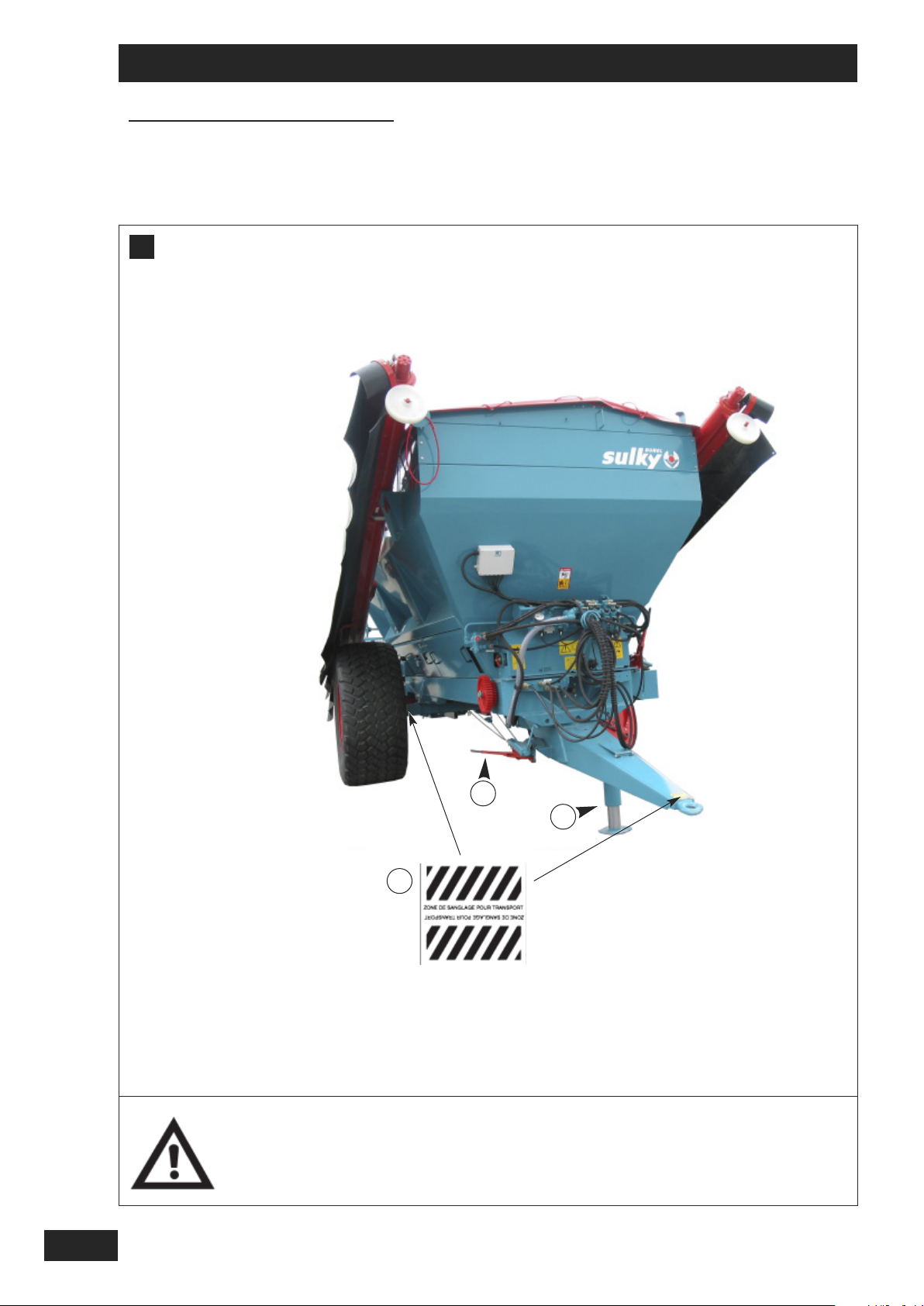
Transport et réception du matériel
A
Vérifier soigneusement que votre machine n’a pas été
endommagée pendant le transport et qu’il ne manque
aucune pièce. Eventuellement, faire les réserves nécessaires
sur le récépissé et les confirmer dans un délai de 48 heures
par lettre recommandée au transporteur.
Lors d’un transport, se conformer aux règles de sécurité
suivantes :
La béquille doit être en position basse,
Tirer le levier de frein de stationnement,
Arrimer le matériel sur les «zones de sanglage
pour transport» prévu à cet effet.
Remarques
Transport and delivery
A
Check the machine carefully for any damage that may have
occurred during transit and for missing parts. Note any
reserves on the delivery slip and then to the carrier by
recorded delivery letter within 48 hours.
Always observe the following safety instructions when the
machine is being transported:
The parking stand must be lowered,
Apply the parking brake ,
Secure the equipment using the “transport strap
NB:Storage conditions: Store the machine empty on a slope
: Conditions de stockage : à vide sur une pente
inférieure à 10%, freins correctement serrés.
attachments” provided
of less than 10%, with the brakes correctly applied.
• Vérifications préalables à toute utilisation
Contrôle serrage
Vérifier que tous les boulons de la machine sont bien serrés.
A
TTENTION.
Après 1 heure de travail:
. resserrer les écrous de roues, le couple de serrage doit
être compris:
- entre 19 et 21 m.daN pour les essieux à 8 goujons
Ø 18 par tambour.
- entre 40 et 42 m.daN pour les essieux à 10 goujons
Ø 22 par tambour.
Après 8 heures de travail:
. vérifier le serrage des roues et des écrous de roues.
• Checks before each use
Torque check
Make sure that the bolts are properly tightened.
TTENTION.
A
After 1 operating hour:
. retighten the wheel nuts to between:
- 19 and 21 m/daN on axles with 8 x Ø 18 studs
per drum.
- 40 and 42 m/daN on axles with 10 x Ø 22 studs
per drum.
After 8 operating hours:
. check the tightness of the wheels and the wheel nuts
1
B
G
Transport und Abnahme der Maschine
A
Bei Annahme ihrer Maschine bitte sorgfältig prüfen, ob die
Maschine nicht während des Transports beschädigt wurde
und ob kein Teil fehlt. Eventuelle Vorbehalte auf dem
Empfangsschein vermerken und dem Spediteur innerhalb
von 48 Stunden per Einschreiben bestätigen.
Anheben der Maschine mittels der 4 Verankerungspunkte an
den 4 oberen Ecken des Tanks.
Beim Transport bitte folgende Sicherheitshinweise beachten:
- Die Abstellstütze muss in abgesenkter Position sein.
- Parkbremse ziehen,
- Maschine an den dazu vorgesehenen
„Transportgurtbereichen“ festmachen.
Anmerkungen : Stillegungsbedingungen: leer bei einer
Neigung unter 10%, Parkbremse angezogen.
• Prüfungen vor jedem Maschineneinsatz
Anziehen der Schrauben
Prüfen, dass alle Schrauben und Muttern richtig angezogen
sind.
A
CHTUNG.
Nach 1 Arbeitsstunde:
. Radmuttern anziehen, das Anziehdrehmoment muss
zwischen folgenden Werten liegen:
- 19 und 21 m.daN bei Achsen mit 8 Stiftbolzen Ø 18
pro Bremstrommel
- 40 und 42 m.daN bei Achsen mit 10 Stiftbolzen Ø 22
pro Bremstrommel
Nach 8 Arbeitsstunden:
. Prüfen, ob die Räder und Radmuttern richtig
angezogen sind.
DE
13
Page 16
Mise en route
Start-up
Inbetriebsetzung
B
//
1
14
Vérifier qu’il n’y ait personne
autour de la machine
pendant l’attelage.
Make sure that nobody is
near the machine during
hitching.
Vor dem Ankoppeln
sicherstellen, dass sich
niemand im
Maschinenbereich befindet
Page 17

Mise en route
Start-up
Inbetriebsetzung
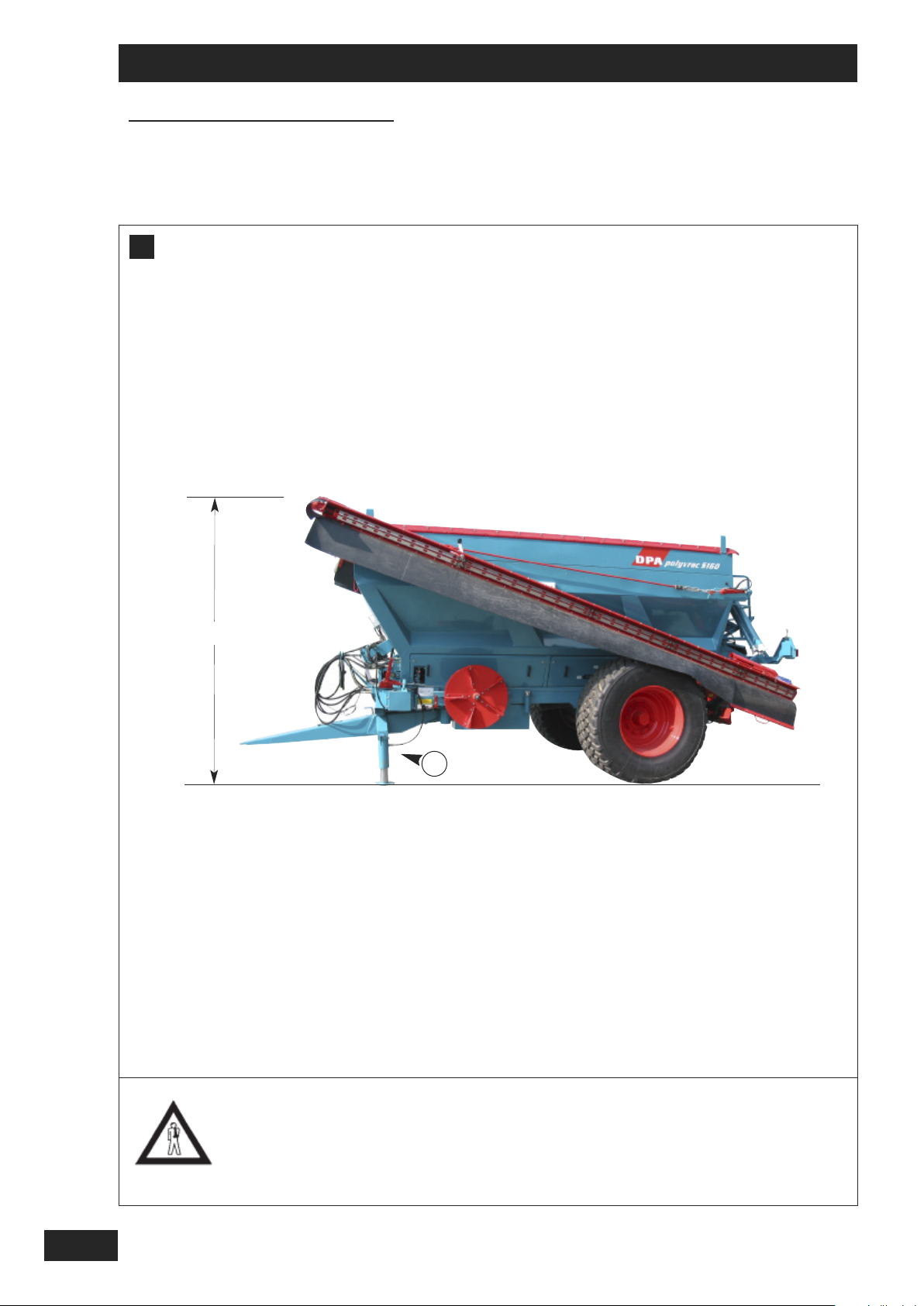
Attelage
B
Atteler la machine au tracteur au moyen de la béquille
(attelage bas) et régler la flèche à une hauteur telle que le
bord supérieur de la caisse soit le plus proche de
l’horizontale, ce qui correspond à la position optimale de
travail des disques ou des rampes.
Pendant les opérations d’attelage, ou de dételage, veiller à
ce que l’axe de verrouillage de la béquille soit
correctement verrouillé.
FR
Hitching
B
Hitch the machine to the tractor using stand (low
hitch) and adjust the drawbar height until the top edge of
the box is as close as possible to horizontal, i.e. the most
efficient disc and boom working position.
When hitching or uncoupling, make sure that the parking
stand’s locking pin is secure.
Ankopplung
B
Maschine mit der Stütze an den Schlepper ankuppeln
(untere Ankupplung) und Ausleger in der Höhe so
einstellen, dass der obere Fahrgestellrand sich so weit wie
möglich in horizontaler Lage befindet; dies entspricht der
optimalen Arbeitsposition der Scheiben oder Rampen.
G
DE
B
Beim An- oder Abkoppeln darauf achten, dass die
Verriegelungsachse der Stütze richtig verriegelt ist.
15
Page 18
Mise en route
Start-up
Inbetriebsetzung
C
L mini
X
1
L maxi
1/2 X
3 cm
2
35°
3
4
35°
2
Travailler avec une
transmission protégée en
bon état, conforme aux
normes en vigueur.
Respecter le régime de
prise de force de 540
tr/min.L’inobservation de
cette précaution entraînerait
des dommages au
mécanisme qui ne seraient
pas couverts par la garantie.
4
When working, the PTO
guards must be fitted and in
good condition, and meet
applicable standards.
Do not exceed a PTO speed
of 540 rpm. Failure to follow
these precautions may
result in mechanical
damage which would not be
covered by the warranty.
4
5
Stets mit einer geschützten
und voll funktionsfähigen
Antriebswelle nach den
geltenden Standards
arbeiten.
Zapfwellendrehzahl von 540
U/min beachten. Ohne diese
Vorsichtsmaßnahmen
könnte der Mechanismus
beschädigt werden; diesen
Schaden würde die Garantie
nicht übernehmen.
16
Page 19

Mise en route
Start-up
Inbetriebsetzung
FR
Prise de force et hydraulique
C
• Le régime est de 540 Tr/mn. (en option 1000 tr/mn)
• Lire attentivement la notice jointe avec la prise de force.
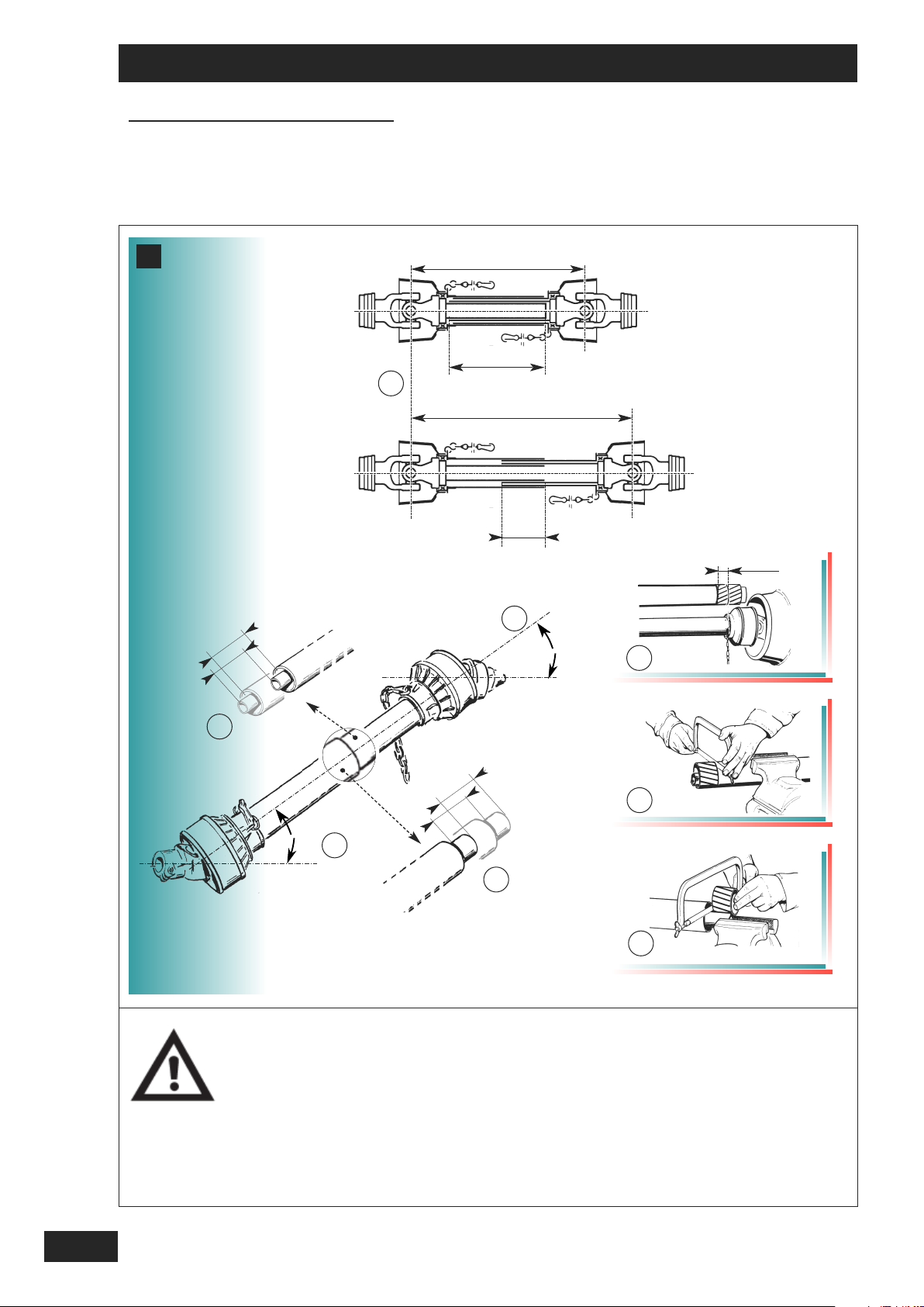
• Angle de la transmission :
Pour garder votre cardan en bon état de fonctionnement,
respecter les positions de travail dans la limite de l’angle
maximum de 35°.
• Montage :
- Graisser l’arbre d’entrée du renvoi de l’appareil avant
d’emboîter la transmission.
• Longueur du cardan :
- Vérifier que la longueur du cardan est bien adaptée à
votre tracteur.
Power take-off and hydraulic system
C
• PTO speed is 540rpm (1,000 rpm available as optional)
• Read the instructions included with the PTO carefully.
• PTO angle:
To keep your universal joint in good condition, do not
exceed the maximum working angle of 35º.
• Installation:
- Lubricate the transmission input shaft before inserting
the PTO shaft.
• Universal shaft length:
- Make sure that the length of the universal shaft is suited
to your tractor.
Remarque:
Attention à la longueur maximale au travail (L maxi).
- Pour la mise à longueur, mettre les deux demitransmissions côte à côte dans leur plus courte position
de travail et les repérer.
Laisser un jeu de 3 cm à chaque extrémité.
- Raccourcir les tubes protecteurs intérieurs et extérieurs
de la même longueur.
- Raccourcir les profils coulissants intérieurs et extérieurs
de la même longueur que les tubes protecteurs.
- Arrondir les bords et nettoyer soigneusement la limaille.
-Graisser les profils coulissants.
NB:
Be careful not to exceed the maximum working angle
(max. L).
- To adjust to the right length, place the two half-shafts
side by side in their shortest working position and mark off
the length.
Leave 3 cm clearance at each end.
- Shorten the inner and outer guard tubes to the same
length.
- Shorten the inner and outer sliding sections to the same
length as the guard tubes.
B
G
Zapfwelle und Hydraulik
C
• Die Zapfwellendrehzahl beträgt 540 U/min. (optionsweise
1000 U/min).
• Benutzungsanweisung der Zapfwelle sorgfältig lesen.
• Anwendungswinkel der Gelenkwelle:
Damit Ihre Gelenkwelle voll funktionsfähig bleibt, müssen
die Arbeitsstellungen auf einen Winkel von maximal 35°
begrenzt sein.
• Montage:
- Antriebswelle des Gerätevorgeleges der Maschine vor
Einhängen der Gelenkwelle schmieren.
• Länge der Gelenkwelle:
- Sicherstellen, dass die Länge der Gelenkwelle an Ihren
Schlepper angepasst ist.
- Smooth the edges and be sure to remove all the filings.
- Lubricate the sliding sections.
DE
Anmerkung:
Maximale Arbeitslänge ( L max.) beachten.
- Bei der Längenanpassung die beiden Halbgelenkwellen
Seite an Seite in die kürzeste Arbeitsposition bringen und
markieren.
3 cm Spiel an jedem Ende lassen.
- Innere und äußere Schutzrohre auf die gleiche Länge
kürzen.
- Innere und äußere aufschiebbare Profile auf die gleiche
Länge wie die Schutzrohre kürzen.
- Kanten abrunden und Feilspäne sorgfältig reinigen.
- Aufschiebbare Profile schmieren.
17
Page 20
Mise en route
Start-up
Inbetriebsetzung
C
18
Essieux suiveurs sur D190,
le bloquer pour les marches
arrières et sur route.
Lock the tag axles on the
D190 for travelling in
reverse or on public roads.
Nachlaufachsen an D190,
beim Rücksetzen und
Straßentransport blockieren.
Page 21

Mise en route
Start-up
Inbetriebsetzung
FR
• La prise de force est équipée d’un limiteur de couple qui
stoppe la transmission lorsque le couple dépasse la valeur
de tarage. Il se réengage automatiquement en réduisant la
vitesse ou en arrêtant la PTO.
• Raccorder les prises d’huile au tracteur et vérifier le
freinage hydraulique.
EXEMPLE DE RACCORDEMENT À EFFECTUER.
TYPE
’ÉQUIPEM ENT
D
FONCTIONS
DPA 1 SE 1 SE 1 SE 1 SE
TRAPPE DOUBLE 2 DE 2 DE 2 DE 2 DE
REPLIAGE ///1 DE
M
OTE UR / / 1 DE /
PLATEAUX PLATEAUX
MÉCANIQUES MÉCANIQUES
VRAC HUMIDE POLYVALENT
PLATEAUX RAMPES
HYDRAULIQUES MÉCANIQUES
(SE = Simple effet, DE = Double effet)
• The PTO includes a slip clutch to stop transmission if the
torque exceeds the calibration setting. The slip clutch is
automatically engaged again when the PTO speed is
reduced or the PTO is stopped.
• Connect the oil valve to the tractor and check the
hydraulic braking system.
EXAMPLE OF CONNECTION
TYPE OF
EQUIPMENT
FUNCTIONS
DPA 1 SE 1 SE 1 SE 1 SE
DOUBLE FLAP 2 DE 2 DE 2 DE 2 DE
FOLD AWAY ///1 DE
ENGINE / / 1 DE /
MECHANICAL MULTIPURPOSE
PLATES FOR MECHANICAL
WET BULK PLATES
HYDRUALIC MECHANICAL
PLATES BOOMS
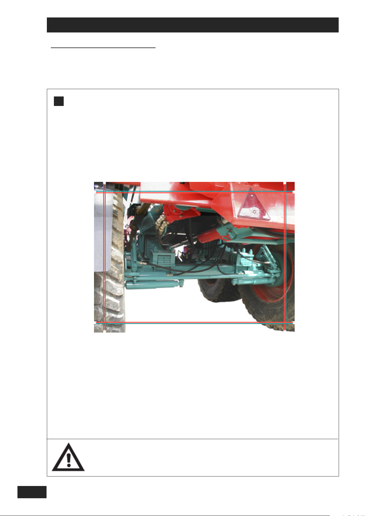
• Accrocher le câble de sécurité situé sur le levier de frein
de stationnement à un point d’ancrage solide à l’arrière du
tracteur. Le câble doit resté détendu lors du braquage de
l’ensemble tracteur/machine.
• Raccorder la prise électrique d’éclairage.
• Pour le D190 raccorder la prise d’huile.
Pour l’essieu suiveur, il faut le bloquer pour effectuer
certaines manoeuvres et notamment les marches arrières
et sur la route.
• Attach the parking brake safety cable to a sturdy bearing
point behind the tractor. The cable should remain slack
when the tractor/machine assembly is turning.
• Connect the electrical lighting socket.
• Connect the oil valve when using a D190.
The tag axle has to be locked when carrying out certain
manoeuvres, especially reversing and road travel.
B
G
(SA = Single action, DA = Double action)
• Der Zapfwellenantrieb ist mit einem
Drehmomentbegrenzer ausgestattet, der die
Kraftübertragung stoppt, wenn das Drehmoment den
Tarierwert übersteigt. Die Kraftübertragung setzt
automatisch wieder ein, wenn die Geschwindigkeit
reduziert oder die Zapfwelle gestoppt wird.
• Hydraulikanschlüsse an den Schlepper anschließen und
Hydraulikbremsung prüfen.
B
EISPIEL FÜR DIE DURCHZUFÜHRENDE ANKOPPLUNG.
AUSRÜSTUNGSTYP:
UNKTIONEN
F
DPA 1 SE 1 SE 1 SE 1 SE
DOPPELKLAPPE 2 DE 2 DE 2 DE 2 DE
HOCHKLAPPFUNKTION ///1 DE
M
OTOR / / 1 DE /
MECHANISCHE MECHANISCHE
STREUSCHEIBEN MEHRZWECK
FÜR FEUCHTES
SCHÜTTGUT
STREUSCHEIBEN UNGSRAMPEN
HYDRAULISCHE MECHANISCH E
STREUSCHEIBEN AUSBRING-
(SE = Einfachwirkung, DE = Doppelwirkung)
DE
• Sicherheitskabel am Parkbremsenhebel an einen soliden
Verankerungspunkt hinten am Schlepper anhängen. Das
Kabel muss beim Einschlagen der SchlepperMaschinenkombination zugfrei bleiben.
• Elektrischen Beleuchtungsstecker anschließen.
• Für den D190 Hydraulikstecker anschließen.
Nachfolgeachse bei bestimmten Handhabungen
blockieren, insbesondere beim Rücksetzen und beim
Straßentransport.
19
Page 22
Mise en route
Start-up
Inbetriebsetzung
C
R
EPÉRAGE DES FONCTIONS
HYDRAULIQUES
L
OCATING THE HYDRAULIC
M
ARKIERUNG DER HYDRAULISCHEN
FUNCTIONS
F
UNKTIONEN
S
IGNIFICATIONS DESPICTOGRAMMES
M
EANING OF THE DIAGRAMS
BEDEUTUNG DER PIKTOGRAMME
1
1
7
7
2
2
3
3
4
4
5
5
6
6
8
8
9
9
10
10
11
11
12
12
20
Essieux suiveurs sur D190, le
bloquer pour les marches
arrières et sur route.
Lock the tag axles on the
D190 for travelling in reverse
or on public roads.
Nachlaufachsen am D190
beim Rücksetzen und
Straßentransport blockieren
Page 23

Mise en route
Start-up
Inbetriebsetzung
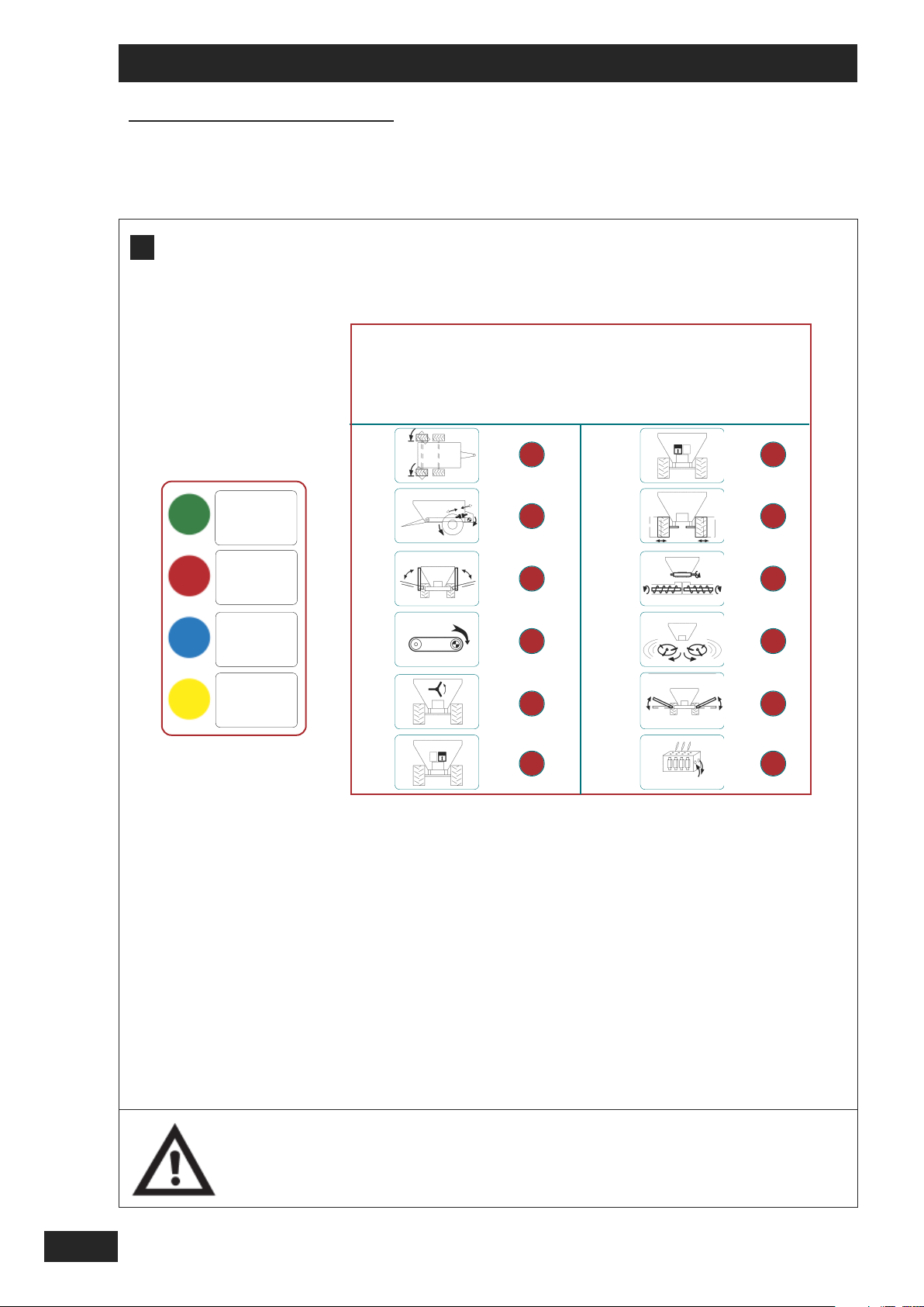
Signification des pictogrammes pour les fonctions hydrauliques :
FR
Essieux suiveurs
1
Embrayage du tapis
2
Repliage rampe
3
Vidange à l’arrêt
4
Dévouteur
5
Trappe droite
6
Trappe gauche
7
Voie variable
8
Meaning of the hydraulic function diagrams:
1
Tag axles
2
Engaging the conveyor belt
3
Folding the booms
4
Emptying when stopped
Rotation moteur rampes et tapis
9
Rotation moteur disque
10
Devers droit et gauche
11
12
Blocs de distribution
9
Booms and conveyor belt motor rotation
10
Disc motor rotation
11
Left and right cant control (angle correction)
12
Distribution assemblies
B
G
5
Anti-bridging device
6
Right shutter
7
Left shutter
8
Variable width
Bedeutung der Piktogramme bei den hydraulischen Funktionen:
Nachlaufachsen
1
Einkuppeln des Förderbands
2
3
Einklappen der Ausleger
Hydraulikölwechsel bei Stillstand
4
5
Gelenkrührwerk gegen Brückenbildung
Rechter Streuschieber
6
Linker Streuschieber
7
Änderung Spurweite
8
Motordrehzahl Ausleger und Förderband
9
10
Motordrehzahl Streuscheibe
Schräglauf rechs und links
11
Verteilerblöcke
12
DE
21
Page 24
Mise en route
Start-up
Inbetriebsetzung
D
4
2
1
4
3
22
Pour éviter d’endommager la
machine, il est vivement
conseillé d’être deux pour le
montage.
It is strongly recommended
that two people perform
fitting work to prevent
damage to the machine.
Um die Maschine nicht zu
beschädigen, wird dringend
geraten, bei der Montage zu
zweit zu arbeiten.
Page 25

Mise en route
Start-up
Inbetriebsetzung
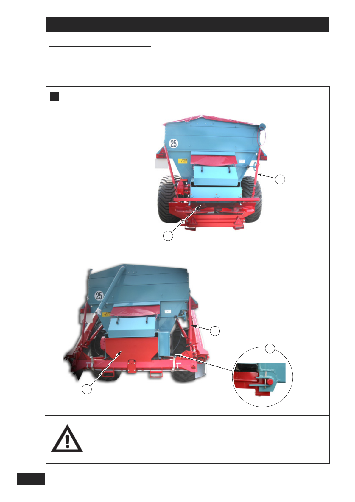
Montage du dispositif d’épandage:
D
Version mécanique
• Positionner le dispositif d’épandage à l’aide d’un chariot
élévateur à fourches.
• Engager le tube transversal dans les mâchoires des
supports inférieurs solidaires du châssis de l’épandeur.
• Relever le dispositif d’épandage jusqu’à ce que sa
face supérieure soit au contact avec le dessous du support
d’entraînement du tapis.
• Accrocher les suspentes , les tendre modérément en
tournant le tube, serrer le contre-écrou.
• Goupiller les mâchoires derrière le tube transversal.
FR
• Mettre le cardan d’entraînement du dispositif d’épandage.
Fitting the spreading mechanism:
D
With the mechanical version
• Use a fork-lift truck to put the spreading mechanism into
position.
• Insert the cross tube into the jaws of the lower brackets
fitted to the spreader chassis.
• Raise the spreading mechanism so that its top surface
is touching the underside of the conveyor drive housing.
• Attach the slings and turn the tube to tighten slightly;
tighten the locknut.
• Secure the jaws into place behind the cross tube.
• Fit the spreader mechanism drive shaft.
Montage der Streuvorrichtung:
D
Mechanische Streuvorrichtung
• Streuvorrichtung mittels eines Gabelstaplers in Position
bringen.
G
DE
B
• Transversalrohr in die Klemmbacken der unteren Halter
des Streuerschassis einführen.
• Streuvorrichtung anheben, bis die obere Fläche in
Kontakt mit der Unterseite des Förderbandantriebs ist.
• Die Aufhänger anhängen, durch Drehen des Rohrs leicht
spannen, Gegenmutter anziehen.
• Klemmbacken hinter dem Transversalrohr befestigen.
• Kardanwelle der Streuvorrichtung anbringen.
23
Page 26
Mise en route
Start-up
Inbetriebsetzung
E
S 80
S 120
S 160
24
Veillez, lorsque le tracteur
est braqué, et afin d’éviter
toutes détériorations, que les
pneumatiques ne viennent
pas en contact avec
l’épandeur ou certains de
ses composants.
Pendant tous les
déplacements, au travail ou
sur la route, l’échelle doit
être totalement repliée.
Respecter la législation en
vigueur pour la circulation
sur route.
When the tractor is turning,
make sure that the tyres do
not touch the spreader or
any spreader parts as this
may cause damage.
The ladder must be folded
back fully when travelling
either during work or on the
road.
Always follow the applicable
Highway Code regulations.
Um Beschädigungen zu
vermeiden muss darauf
geachtet werden, dass die
Reifen beim Einschlagen des
Schleppers nicht mit dem
Streuer oder seinen
Bestandteilen in Berührung
kommen.
Bei der Feldarbeit oder beim
(Straßen)-Transport muss
die Leiter vollständig
hochgeklappt sein.
Beim Straßentransport die
geltenden Bestimmungen
einhalten.
Page 27

Mise en route
Start-up
Inbetriebsetzung
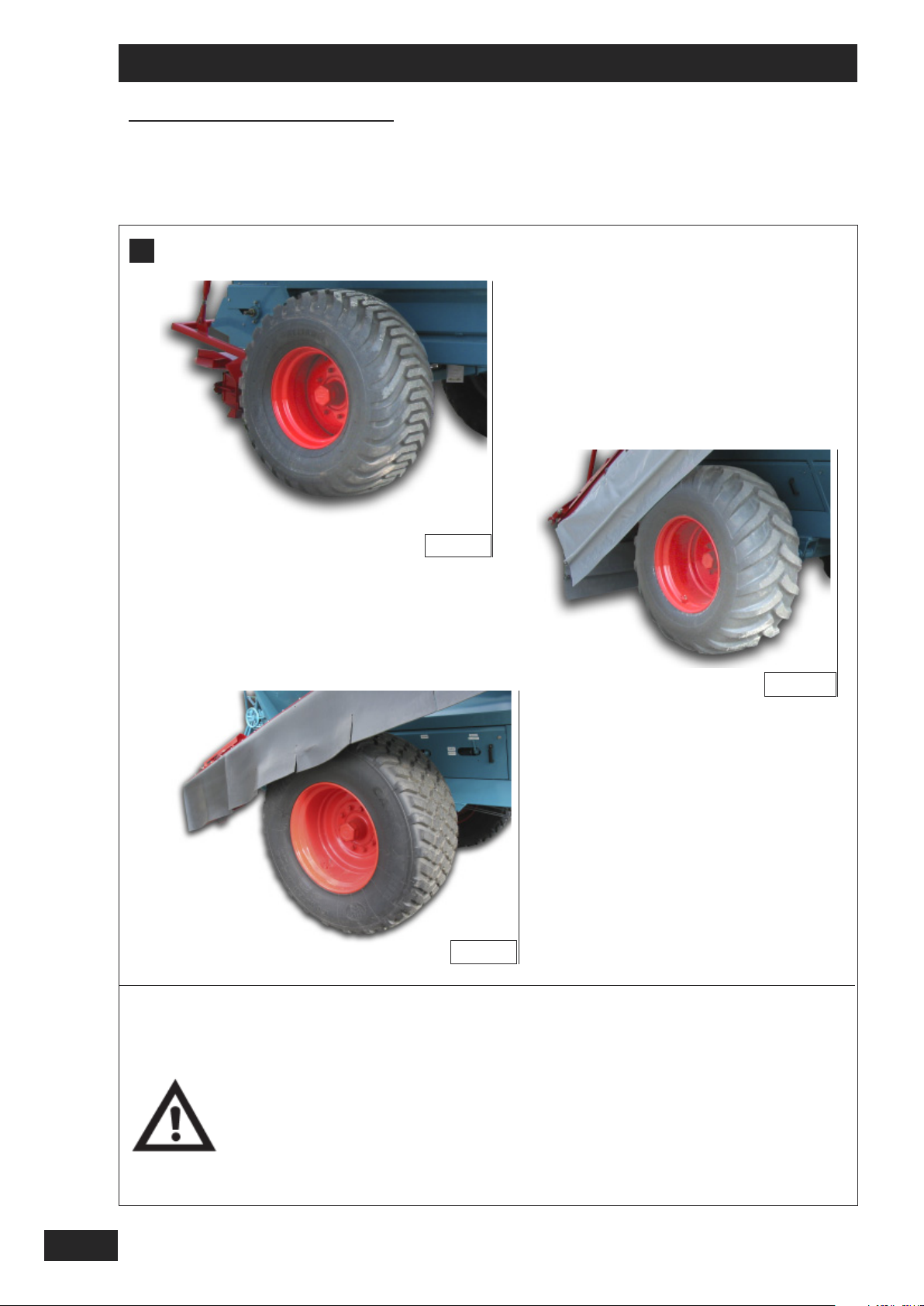
Pneumatiques
E
GABARIT: Certaines machines peuvent être homologuées en
autorisant des montes de pneumatiques de forte largeur.
Dans ce cas la largeur hors-tout des machines peut excéder
2,55m sans dépasser 3,00m à la seule condition que ce
dépassement ne soit causer que par les pneumatiques, le
reste de la machine ne doit pas dépasser 2,55m. Dans ce
cas, la machine est en configuration «hors code».
Une circulation sur route avec une machine dont les
pneumatiques dépassent la largeur de 2,55m sans dépasser
3,00m, est soumise à autorisation préfectorale.
Veuillez consulter les arrêtés préfectoraux des départements
dans lesquels la machine va se déplacer.
En l’absence d’homologation et d’autorisation préfectorale,
un dépassement de largeur est autorisé exclusivement
pendant une utilisation aux champs.
Dans tous les cas n’utiliser que les pneumatiques indiqués
dans le tableau ci-dessous.
Tyres
E
SIZE: Some machines may be approved for extra-width tyres.
If such tyres are fitted the overall vehicle width can exceed
2.55 m but not 3.00 m, provided that the extra width is only
caused by the tyres and that the rest of the vehicle does not
exceed 2.55 m. In this case, the vehicle configuration is
beyond French highway code regulations.
A permit is required to drive on public roads in a vehicle
whose tyres cause the overall width to exceed 2.55 m whilst
remaining within the 3.00 m limit.
Please consult the local laws covering the areas in which the
machine will be driven.
If no approval or authorization exists, the machine may only
be permitted to exceed the stipulated width
during use in the field.
The machine should only ever be fitted with the tyres in the
following table.
DÉSIGNATION PRESSION DE GONFLAGE
PNEUMATIQUES
S 80 550/60 - 22,5 12 PR 2,0 bars
600/55 - 22,5 12 PR 1,6 bars
600/55 - 26,5 12 PR 1,5 bars
700/50 - 26,5 12 PR 1,3 bars
18.4 R38 - 149 A 8 1,6 bars
18.4 R42 - 148 A 8 1,6 bars
S 120 600/55 - 26,5 12 PR 2,2 bars
700/50 - 26,5 12 PR 1,8 bars
710/50 - 26,5 170 D 1,5 bars
600/60 - 30,5 12 PR 2,1 bars
700/50 - 30,5 12 PR 1,7 bars
S 160 600/60 - 30,5 12 PR 2,5 bars
700/50 - 30,5 12 PR 1,9 bars
650/65 - 30,5 12 PR 1,8 bars
750/60 - 30,5 12 PR 1,4 bars
S 190 600/55 - 22,5 12 PR 2,0 bars
560/60 - 22,5 161 D 1,5 bars
CIRCULATION MIXTE
ROUTE
Spécification Fabricants
TYRE TYRE PRESSURE
TYPE COMBINED ROAD
S 80 550/60 - 22,5 12 PR 2.0 bars
600/55 - 22,5 12 PR 1.6 bars
600/55 - 26,5 12 PR 1.5 bars
700/50 - 26,5 12 PR 1.3 bars
18.4 R38 - 149 A 8 1.6 bars
18.4 R42 - 148 A 8 1.6 bars
S 120 600/55 - 26,5 12 PR 2.2 bars
700/50 - 26,5 12 PR 1.8 bars
710/50 - 26,5 170 D 1.5 bars
600/60 - 30,5 12 PR 2.1 bars
700/50 - 30,5 12 PR 1.7 bars
S 160 600/60 - 30,5 12 PR 2.5 bars
700/50 - 30,5 12 PR 1.9 bars
650/65 - 30,5 12 PR 1.8 bars
750/60 - 30,5 12 PR 1.4 bars
S 190 600/55 - 22,5 12 PR 2.0 bars
560/60 - 22,5 161 D 1.5 bars
FIELD USE
Manufacturers’ specifications
/CHAMPS
FR
B
G
/
DE
Bereifung
E
AUßENMAß: Einige Maschinen sind für breite Bereifung
zugelassen.
In diesem Fall darf das Gesamtaußenmaß der Maschinen
2,55 m überschreiten (bis 3,00 m sind erlaubt), wenn die
Maßüberschreitung ausschließlich von den Reifen erzeugt
wird. Die eigentlichen Maschinenmaße müssen auf 2,55 m
beschränkt sein. In diesem Fall wird die Maschine als „nicht
maßhaltig“ bezeichnet.
Beim Straßentransport mit einer Maschine, deren Außenmaß
aufgrund der Bereifung zwischen 2,55 m und 3,00 m liegt,
bedarf es in Frankreich einer Genehmigung durch die
Präfektur.
In diesem Fall die Präfekturverordnungen der Departements
einsehen, in denen die Maschine gefahren werden soll.
Ohne Zulassung und Präfekturgenehmigung ist die
Überschreitung des Gesamtaußenmaßes ausschließlich zur
Feldarbeit erlaubt.
In allen Fällen nur die in untenstehender Tabelle aufgeführte
Bereifung verwenden.
BEZEICHNUNG REIFENDRUCK BER EIFUNG
BEREIFUNG GEMISCHTEINSATZ
S 80 550/60 - 22,5 12 PR 2,0 Bar
600/55 - 22,5 12 PR 1,6 Bar
600/55 - 26,5 12 PR 1,5 Bar
700/50 - 26,5 12 PR 1,3 Bar
18.4 R38 - 149 A 8 1,6 Bar
18.4 R42 - 148 A 8 1,6 Bar
S 120 600/55 - 26,5 12 PR 2,2 Bar
700/50 - 26,5 12 PR 1,8 Bar
710/50 - 26,5 170 D 1,5 Bar
600/60 - 30,5 12 PR 2,1 Bar
700/50 - 30,5 12 PR 1,7 Bar
S 160 600/60 - 30,5 12 PR 2,5 Bar
700/50 - 30,5 12 PR 1,9 Bar
650/65 - 30,5 12 PR 1,8 Bar
750/60 - 30,5 12 PR 1,4 Bar
S 190 600/55 - 22,5 12 PR 2,0 Bar
560/60 - 22,5 161 D 1,5 Bar
STRAßE/FELD
Herstellerspezifikationen
25
Page 28
Mise en route
Start-up
Inbetriebsetzung
F
1
26
Intervenir dans la trémie
seulement lorsque le
tracteur est à l’arrêt.
Work should only be
carried out in the
hopper when the tractor
is stationary.
Arbeiten am Trichter nur
bei Schlepperstillstand
durchführen.
Page 29

Mise en route
Start-up
Inbetriebsetzung
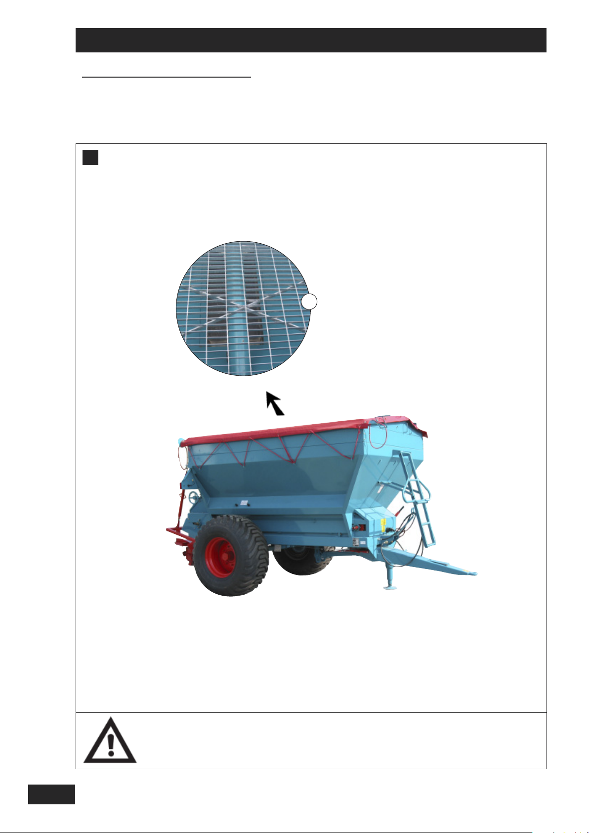
Contrôler le bon emplacement des grilles anti-motte
F
Si votre épandeur est équipé de réhausses et d’un jeu de
grilles anti-motte
placées dans la réhausse supérieure (les barres de renfort
toujours vers le bas) et non dans la trémie, afin d’éviter les
éventuelles déformations du matériel.
Lorsqu’il n’y a pas de réhausse, les grilles sont à placer dans
la trémie (les barres de renfort également vers le bas),
comme sur la photo
, veillez à ce que celles-ci soient bien
.
FR
Check that the anti-clod screens are in the correct
F
position
If your spreader includes extensions and a set of anti-clod
screens
, make sure the screens are in the proper position
on the upper extension (with the struts always facing down)
and not in the hopper, otherwise the equipment may become
misshapen.
If no extension is fitted, place the screens in the hopper
(with the struts still facing down), as shown in photo
Kontrollieren, ob die Klumpenschutzroste an der
F
richtigen Stelle angebracht sind.
Ist Ihr Streuer mit Trichteraufbau und Klumpenschutzrosten
ausgestattet, darauf achten, dass sich diese im oberen
Trichteraufbau (Verstärkungsstangen nach unten) und nicht
im Trichter befinden, um mögliche Beschädigung zu
vermeiden.
Liegt kein Trichteraufbau vor, sind die Roste im Trichter
anzubringen (Verstärkungen ebenfalls nach unten), wie auf
Foto
.
.
G
DE
B
27
Page 30

Mise en route
Start-up
Inbetriebsetzung
G
28
Il est préférable de vider
complètement la trémie
avant le chargement.
Afin d’éviter un éventuel
blocage lors du
redémarrage.
Ideally, the hopper
should be emptied
completely before it is
filled. This is to prevent
a blockage occurring
when the machine is
restarted.
Trichter vor dem Füllen
wenn möglich
vollständig entleeren.
Um mögliche
Blockierung beim
Anlaufen zu vermeiden.
Page 31

Mise en route
Start-up
Inbetriebsetzung
FR
Chargement de la trémie
G
• Le chargement par godet : afin d’éviter de déplacer les
grilles anti-mottes, veiller à ce que les chargements ne
soient pas brusques.
• Le chargement par remplissage pneumatique : afin d’éviter
la compression dans la trémie décrocher les sandows
uniquement à l’arrière de la trémie.
DÉBUT DE L’ÉPANDAGE APRÈS UN NOUVEAU CHARGEMENT:
Si la machine a bien été complètement vidée avant d’être
rechargée, le redémarrage ne pose aucun problème.
Toutefois, un long trajet chargé peut provoquer un tassement
de l’engrais, et un blocage au redémarrage.
Dans ce cas, le blocage se produit dans les 50 cm situés
juste avant la trappe; au redémarrage, la sécurité située sur
Loading the hopper
G
• Loading with a bucket: load the hopper slowly to avoid
knocking the anti-clod screens out of position.
• When using a pneumatic loading system: only detach the
straps at the rear of the hopper. This will prevent
compaction inside the hopper.
la transmission DPA, (limiteur de couple à cames et
ressorts) se déclenche.
Il suffit alors de débloquer sur cette longueur (manche de
pelle pour déstabiliser la masse d’engrais bloquée), pour que
la machine reparte normalement.
A la fin de la journée de travail, vous devez vider
complètement la trémie.
restarted.
The blockage needs simply to be removed along this length
(use a shovel handle to break up the fertilizer causing the
blockage) to be able to restart the machine.
When work is over for the day, the hopper must be emptied
completely.
B
G
S
PREADING AFTER THE HOPPER HAS BEEN REFILLED:
The machine will start up again without any problem if it was
completely emptied before being refilled.
Nevertheless, the fertilizer may become compacted during a
long journey, causing a blockage when the machine is
restarted.
If a blockage occurs it will be in a 50-cm area just behind
the flaps; the safety system on the DPA shaft (cam and
spring type slip clutch) will be activated when the machine is
Füllen des Trichters
G
• Kübelfüllung: Um die Klumpenschutzroste nicht abnehmen
zu müssen, darf der Füllvorgang nicht zu schnell ablaufen.
• Luftdruckbetriebenes Füllen: um die Streugutverdichtung
im Trichter zu vermeiden, Gummiseile nur hinten am
Trichter abnehmen.
B
EGINN DER AUSBRINGUNG NACH DEM FÜLLEN.
Wenn die Maschine vor dem Füllen vollständig geleert
wurde, läuft die Streuung problemlos wieder an.
Eine lange Fahrt mit gefülltem Trichter kann zur Verdichtung
des Streugutes und zur Blockierung beim Anlaufen führen.
In diesem Fall setzt sich das Streugut in den 50 cm oberhalb
der Klappe fest; beim Anlaufen wird die
Sicherheitsvorrichtung auf der DPA-Gelenkwelle
(Nockenreibkupplung mit Federn) ausgelöst.
DE
Das Streugut braucht nur bis in diese Höhe gelockert zu
werden (mit dem Spatenstiel Streugutmasse lockern), dann
läuft die Maschine wieder normal an.
Nach der Streuarbeit Trichter vollständig entleeren.
29
Page 32

Réglages
Settings
Einstellungen
A
1
2
Avant utilisation, consulter
le manuel d’utilisation et
respecter les règles de
sécurité.
Contrôler régulièrement la
tension du tapis.
Read the user manual
before use and follow the
safety instructions.
Check the tension of the
conveyor belt at regular
intervals.
Vor dem Einsatz
Betriebshandbuch
konsultieren und
Sicherheitsvorschriften
beachten.
Regelmäßig die Spannung
des Förderbandes
kontrollieren.
30
Page 33

Réglages
Settings
Einstellungen
FR
Réglage de la machine
A
• Poutre d’éclatement
Pour l’épandage de la plupart des produits, la poutre d’éclatement
longitudinale élimine les problèmes de tassement au chargement et
pendant le transport. Elle supprime les effets de voûte pendant
l’extraction. On obtient ainsi une alimentation constante du produit
jusqu’à la vidange totale de la trémie. La machine assure donc un
épandage régulier de tous types d’engrais granulés et
d’amendements secs ou humides, et de produits particulièrement
difficiles à épandre, comme les produits organiques ou de la chaux
humide.
Certains appareils de forte capacité possèdent, en plus de leurs 2
poutres d’éclatement longitudinales des toits anti-tassement qui
doivent être positionnés de la façon suivante:
- Un premier toit anti-tassement en butée sur la face avant de la
trémie puis un deuxième espacé de 20 cm du premier.
Machine settings
A
• Breaker arm
The lengthways breaker arm eliminates compaction problems
for most products during loading and transport, and prevents
bridging during extraction, maintaining a smooth flow of
product until the hopper is completely empty.
machine to evenly spread all types of granular fertilizer, wet or dry
conditioners, and products that are especially difficult to spread such
as organic products and wet lime.
Some machines with a high payload capacity also include anticompaction baffles in addition to the 2 breaker arms. These baffles
are to be fitted as follows:
- A first anti-compaction baffle is to be placed flush against the
front face of the hopper, with a second baffle 20 cm away from the
first.
This enables the
• Tapis
Il est possible qu’après plusieurs heures de fonctionnement,
et bien souvent lors de la première mise en service, que le
tapis se détende légèrement. On obtiendra alors un
glissement du tambour d’entraînement sous la bande.
REMÈDE:
Tendre le tapis modérément au moyen des 2 paliers tendeurs,
afin d’obtenir une adhérence suffisante. Pour éviter que le tapis se
déporte, ce qui provoquerait son usure prématurée, il convient de
tendre les 2 paliers tendeurs de manière identique.
Les guides en ertalon évitent le déplacement du tapis hors
des limites acceptables. Mais ils ne doivent, en aucun cas,
être considérés comme des pièces de frottement permanent.
Afin d’éviter d’éventuels dommages sur la mécanique,
lors d’un effort violent (par exemple : tambour bloqué par
un corps étranger, etc...) le réducteur supérieur de
l’entraînement est protégé par un limiteur de couple à
cames situé sur la transmission à cardan du DPA .
NB: Ce limiteur doit toujours être taré à un couple
de 260 N.m maximum.
• Conveyor belt
The conveyor may slacken slightly after several hours of
operation and especially when it is used for the first time.
This will cause the drive pulley under the belt to lose some
of its grip.
S
OLUTION:
Tension the belt slightly with the 2 take-ups so that it
acquires sufficient grip. To stop the belt from moving out of
true and suffering premature wear, the two take-ups should
both be tensioned the same.
The tracks keep the belt within acceptable limits. They are
not, however, intended to be subject to constant friction.
To prevent any mechanical damage due to severe exertion
(e.g. pulley blocked by an irregular object, etc.), a cam type
slip clutch on the DPA universal joint shaft protects the drive.
NB: This slip clutch must always be calibrated to a maximum
torque of 260 N.m.
2
B
G
Einstellung der Maschine
A
• Zerstreuungsvorrichtung
Mit diesem Streuer können alle granulierten Düngersorten, trockene
und feuchte Bodenverbesserungsmittel sowie auch besonders
schwer auszubringende Produkte regelmäßig ausgebracht werden,
wie z. B. organische Produkte oder Feuchtkalk.
Einige Maschinen hoher Kapazität haben außer den beiden
längsverlaufenden Zerstreuungsvorrichtungen Festdrückschutz.
Diese Vorrichtungen sind folgendermaßen zu installieren:
- Eine erste zum Aufschlag des Streugutes an der Vorderfläche des
Trichters und eine zweite in 20 cm Abstand von der ersten.
• Förderband
Es kann vorkommen, dass sich das Förderband nach
mehreren Betriebsstunden und oft bei der ersten
Inbetriebnahme leicht entspannt. Die Antriebstrommel unter
dem Förderband kann dann seitlich ein wenig wegrutschen.
A
BHILFE:
Förderband mit den 2 Spannlagern nur so stark spannen ,
dass eine ausreichende Haftung entsteht. Damit das
Förderband nicht seitlich wegrutscht, was zum vorzeitigen
DE
Verschleiß führen würde, müssen beide Spannlager gleich
stark gespannt werden.
Die Ertalonführungen verhindern, dass das Förderband
außerhalb der akzeptablen Grenzen wegrutscht. Die
Führungen dürfen keinesfalls als ständige Reibungsteile
angesehen werden.
Um mögliche mechanische Schäden zu verhindern bei
starken Belastungen(zum Beispiel: Trommel durch
Fremdkörper blockiert usw.)ist der obere Antriebsregler
durch eine Nockenreibkupplung auf der Kardanwelle des
DPA geschützt .
NB: Diese Nockenreibkupplung ist stets auf ein
Drehmoment von maximal 260 N einzustellen.
31
Page 34

Réglages
Settings
Einstellungen
B
a)
32
Contrôler le débit, un nouvel
étalonnage peut s'avéver
nécessaire suivant les
conditions.
Check the rate of flow as it may
be necessary to re-calibrate to
suit the conditions
Streumenge überwachen, je
nach Verhältnissen kann eine
neue Eichung notwendig sein.
Page 35

Réglages
Settings
Einstellungen
Réglage du débit
B
a) Réglage
Le DPA est une machine avec distribution dite volumétrique.
Le débit est obtenu en jouant sur la hauteur de la trappe
d'ouverture à la sortie du tapis.
Remarque:
Pour les petits débit/ha (hauteur de trappe ≤ à 4 cm) mettre
en position la deuxième trappe inox (divise le débit par 3).
FR
Adjusting the flow rate
B
a) Adjustment
The DPA machine uses a volumetric metering system.
The application rate is set by manipulating the height of
the outlet flap at the end of the belt.
NB:
When applying a small rate per hectare (flap height ≤ 4 cm,
put the second stainless steel shutter into place (application
rate divided by 3).
Streumengeneinstellung
B
a) Einstellung
Der DPA Streuer hat einen volumetrischen
Streumechanismus.
Die Streumenge ergibt sich aus der eingestellten Höhe
der Klappe am Förderbandausgang.
G
DE
B
Anmerkung:
Bei geringer Streumenge/ ha (Klappenöffnung = 4 cm)
zweite Edelstahlklappe verwenden (die Streumenge wird
gedrittelt).
33
Page 36

Réglages
Settings
Einstellungen
B
b)
34
Page 37

Réglages
Settings
Einstellungen
b) Réglette
La réglette de dosage, fournie avec la machine, permet de lire
directement les réglages à utiliser pour obtenir le dosage désiré, en
fonction de la densité et de la largeur de travail. L’indice de réglage,
dépendant des caractéristiques de la machine, et notamment du
type des roues, est donné à l’arrière de la machine.
La densité à prendre en compte pour le réglage est la densité
d’extraction, c’est-à-dire la densité du produit à la sortie de la
trappe.
Des variations peuvent apparaître selon la nature des produits et
certains paramètres extérieurs tels que l’hygrométrie, la température
ambiante ou le tassement. Il convient donc de contrôler le débit
obtenu, et d’étalonner la réglette en apportant une éventuelle
correction par le choix d’un indice de réglage différent
Remarque:
Si la quantité de produit épandu est moins importante que
celle désirée, choisir un indice de réglage plus fort
----
(0
>25).
Si la quantité de produit épandu est plus importante que
celle désirée, choisir un indice de réglage plus faible
----
(25
>0).
Le tableau ci-dessous donne les «indices de réglage» correspondant
aux principales montes de pneumatiques. L’indice de la machine est
rappelé par un autocollant situé à l’arrière, à proximité de la trappe.
b) Slide calculator
The metering calculator supplied with the machine lets you see
which settings to use in order to apply the required dose, based on
the density and the working width. The setting value depends on
the machine specifications, in particular the type of wheels fitted,
and can be found at the rear of the machine.
The density used to determine the setting is the extraction density,
i.e. the density of the product as it leaves the shutter.
Differences may arise depending on the type of product and
certain external factors such as moisture levels, local
temperature or compaction. The output should therefore be
checked and the slide calculator calibrated by altering the
setting index if necessary.
NB:
If the product is spread in a lower quantity than required,
select a higher setting index.
(0---->25).
If the product is spread in a higher quantity than required,
select a lower setting ratio
(25---->0).
The table below shows the "setting indices" for the main
types of tyre fitted. The machine index is shown on a sticker
at the rear, near to the flap.
b) Skala
Über die mit der Maschine gelieferte Dosierungsskala können die
Einstellungen für die gewünschte Dosierung in Abhängigkeit von der
Saatdichte und der Arbeitsbreite direkt abgelesen werden. Die
Einstellrichtzahl richtet sich nach den Merkmalen der Maschine und
nach dem Reifentyp. Die Zahl ist am Heck der Maschine angezeigt.
Für die Einstellung zu berücksichtigen ist die Ausbringungs-Saatdichte,
d.h. die Saatdichte am Ausgang der Klappe.
Für die Einstellung zu berücksichtigen ist die AusbringungsSaatdichte, d.h. die Saatdichte am Ausgang der Klappe.
Je nach Saatgut und bestimmten äußeren Parametern wie
Luftfeuchtigkeit, Außentemperatur oder Verdichtung können
Variationen in der Saatdichte auftreten. Die Saatdichte muss also
überwacht und die Skala geeicht werden. Bei Bedarf können
Korrekturen durch Wahl einer anderen Einstellrichtzahl
vorgenommen werden.
Anmerkung:
Liegt die ausgebrachte Menge unter der gewünschten
Saatdichte, eine höhere Einstellrichtzahl wählen.
(0---->25).
Liegt die ausgebrachte Menge über der gewünschten
Saatdichte, eine geringere Einstellrichtzahl wählen.
(25---->0).
Untenstehende Tabelle zeigt die „Einstellrichtzahlen“ in
Abhängigkeit von der Bereifung. Die Richtzahl der Maschine
wird zur Erinnerung durch einen Aufkleber am hinteren
Maschinenende in der Nähe der Klappe angegeben.
.
DÉSIGNATION INDICE DE
PNEUMATIQUES
S 80 550/60 - 22,5 12 PR 21 B
600/55 - 22,5 12 PR 22 B
600/55 - 26,5 12 PR 23 B
700/50 - 26,5 12 PR 23 B
18.4 R38 - 149 A 8 18 A
18.4 R42 - 148 A 8 19 A
S 120 600/55 - 26,5 12 PR 9 C
700/50 - 26,5 12 PR 9 C
710/50 - 26,5 170 D 3 B
600/60 - 30,5 12 PR 4 B
700/50 - 30,5 12 PR 4 B
S 160 600/60 - 30,5 12 PR 4 B
700/50 - 30,5 12 PR 4 B
650/65 - 30,5 12 PR 6 B
760/60 - 30,5 12 PR 6 B
S 190 600/55 - 22,5 12 PR 4 B
560/60 - 22,5 161 D 4 B
RÉGLAGE
Autres pneumatiques nous consulter.
TYRE SETTI NG
TYPE INDEX
S 80 550/60 - 22.5 12 PR 21 B
600/55 - 22.5 12 PR 22 B
600/55 - 26.5 12 PR 23 B
700/50 - 26.5 12 PR 23 B
18.4 R38 - 149 A 8 18 A
18.4 R42 - 148 A 8 19 A
S 120 600/55 - 26.5 12 PR 9 C
700/50 - 26.5 12 PR 9 C
710/50 - 26.5 170 D 3 B
600/60 - 30.5 12 PR 4 B
700/50 - 30.5 12 PR 4 B
S 160 600/60 - 30.5 12 PR 4 B
700/50 - 30.5 12 PR 4 B
650/65 - 30.5 12 PR 6 B
760/60 - 30.5 12 PR 6 B
S 190 600/55 - 22.5 12 PR 4 B
560/60 - 22.5 161 D 4 B
Please contact us regarding other tyres.
B
EZEICHNUNG
B
EREIFUNG
S 80 550/60 - 22,5 12 PR 21 B
600/55 - 22,5 12 PR 22 B
600/55 - 26,5 12 PR 23 B
700/50 - 26,5 12 PR 23 B
18.4 R38 - 149 A 8 18 A
18.4 R42 - 148 A 8 19 A
S 120 600/55 - 26,5 12 PR 9 C
700/50 - 26,5 12 PR 9 C
710/50 - 26,5 170 D 3 B
600/60 - 30,5 12 PR 4 B
700/50 - 30,5 12 PR 4 B
S 160 600/60 - 30,5 12 PR 4 B
700/50 - 30,5 12 PR 4 B
650/65 - 30,5 12 PR 6 B
760/60 - 30,5 12 PR 6 B
S 190 600/55 - 22,5 12 PR 4 B
560/60 - 22,5 161 D 4 B
E
INSTELLRICHTZAHL
Bei abweichender Bereifung bei uns um Rat fragen.
FR
G
DE
B
35
Page 38

Réglages
Settings
Einstellungen
B
3
1
2
a)
3
2
1
3
1
b)
2
1
c)
2
3
36
La réglette de dosage est une
réglette polyvalente.
Elle est utilisée également pour des
appareils qui comportent plusieurs
combinaisons possibles de pignons,
ce qui expliquent les 3 vitesses qui y
sont notées.
Cependant, les épandeurs S 80 ont
une vitesse unique qui correspond à
la vitesse moyenne.
Vous devez lire sur la réglette
uniquement l’échelle correspondant
à la vitesse moyenne.
The metering slide calculator has
many uses. It can also be applied
to machines with several possible
gear combinations, which is why
it shows three speeds.
However, S80 spreaders have
one speed (medium). Readings
from the slide calculator must
only be taken using the mediumspeed scale.
Die Dosierungsskala ist für
mehrere Zwecke einsetzbar. Sie
wird ebenfalls für Geräte benutzt,
die verschiedene mögliche
Zahnradkombinationen
umfassen, daher sind 3
Geschwindigkeiten markiert.
Die S80 Streuer haben eine
einzige Geschwindigkeit, die der
mittleren Geschwindigkeit
entspricht. Auf der Skala nur die
Gradeinteilung für die mittlere
Geschwindigkeit ablesen.
Page 39

Réglages
Settings
Einstellungen
EXEMPLES :
FR
1) Votre épandeur est un S80 avec des pneumatiques
550/60 x 22,5 12PR.
LE TABLEAU VOUS DONNE COMME INDICE DE RÉGLAGE : 21 B.
a) Sur votre réglette , positionner l’indice de réglage
21 en face du repère B .
b) Déterminer alors le réglage de l’appareil à l’aide du
curseur , aligner la densité avec la dose / ha
souhaitée en prenant bien garde de maintenir les
deux parties de la réglette dans la même position
relative.
c) A partir de là, il suffit de lire pour une largeur de
travail donnée et une vitesse choisie, l’ouverture en
cm de la trappe de débit.
EXAMPLES :
1) If your spreader is type S80 fitted with 550/60 x 22.5 12PR
tyres.
The setting index shown in the table is: 21 B.
a) Move the setting value 21 so that it is lined up with
mark B on your slide calculator .
b) Then use the pointer to ascertain the machine
setting, line up the density with the target dose per
hectare taking care to keep both parts of the
calculator in the same relative position
c) Now, simply read off the flap opening figure in cm for
a given working width with the selected speed.
• L’ouverture de la trappe se lit directement sur le réglet situé
du côté droit de la trappe.
• L’ouverture donnée par la réglette ou le tableau doit être
mesurée entre le fond du tapis et le bord inférieur de la
trappe.
EXEMPLE:
a) S80 (indice de réglage 21 B)
b) Epandage à 700 kg/ha
- engrais de densité 1Kg/l
c) Pour une largeur de travail de 15 m, prendre pour
référence la combinaison de pignons n°2 (vitesse
moyenne). L’ouverture de la trappe sera de 9 cm.
• Take the reading for the flap opening directly from the ruler
located on the RH side of the flap.
• The opening indicated by the slide calculator or in the table
must be measured between the end of the belt and the
lower edge of the flap.
EXAMPLE:
a) For type S80 (with a setting value of 21 B)
b) The spreading rate is 700 kg/ha
- fertilizer density 1Kg/l
c) If the working width is 15 m
Use gear setup no. 2 (medium speed) as your
reference point. The flap will open by 9 cm.
G
DE
B
BEISPIELE:
1) Ihr Streuer ist ein S80 mit einer 550/60 x 22,5 12PR
Bereifung.
DIE TABELLE GIBT ALS EINSTELLRICHTZAHL AN: 21 B.
a) Auf der Dosierskala die Einstellrichtzahl 21
gegenüber Marke B einstellen.
b) Einstellung der Maschine mit Hilfe des Läufers
bestimmen, Dichte mit der gewünschten
Hektardosierung in Übereinstimmung bringen, wobei
darauf zu achten ist, dass beide Teile der
Dosierungsskala die gleiche relative Position behalten.
c) Anschließend für eine gegebene Arbeitsbreite und die
gewünschte Fahrgeschwindigkeit die Öffnung des
Streuschiebers in cm ablesen.
• Die Klappenöffnung ist rechts von der Klappe direkt von
der Skala ablesbar.
• Die von der Skala bzw. auf der Tabelle angegebene
Öffnung muss zwischen Bandunterseite und unterem
Klappenrand gemessen werden.
BEISPIEL:
a) S80 (Einstellrichtzahl 21 B)
b) Ausbringung bei 700 kg/ha
- Düngerdichte 1Kg/l
c) Bei einer Arbeitsbreite von 15 m
Auf der Gradeinteilung 2. Mittlere
Geschwindigkeitablesen: Klappenöffnung: 9 cm.
37
Page 40

Réglages
Settings
Einstellungen
B
a)
1
3
b) c)
2
2
1
3
1
38
Pour votre sécurité, le
changement de la combinaison
doit se faire impérativement
moteur du tracteur à l’arrêt.
2
3
For safety reasons, the combination
must never be altered unless the
tractor engine is switched off.
Zu Ihrer Sicherheit muss die
Änderung der Kombination
unbedingt bei Stillstand des
Schleppermotors durchgeführt
werden.
Page 41

Réglages
Settings
Einstellungen
FR
2) Votre épandeur est un S 160 avec des pneumatiques
600/60 - 30,5 12PR.
LE TABLEAU VOUS DONNE COMME INDICE DE RÉGLAGE : 4 B.
Sur votre réglette , positionner l’indice de réglage 4 en
face du repère B
Déterminer alors le réglage de l’appareil à l’aide du curseur
.
, en prenant bien garde de maintenir les deux parties de la
réglette dans la même position relative.
L’ouverture de la trappe se lit directement sur le réglet, situé
du côté droit de la trappe. L’ouverture donnée par la réglette
ou le tableau doit être mesurée entre le fond du tapis et le
bord inférieur de la trappe.
Les trois vitesses (1, 2 ou 3) de la bande transporteuse sont
obtenues en combinant les pignons à l’intérieur du carter
arrière droit suivant les schémas .
2) If your spreader is type S 160 fitted with 600/60 – 30.5
12PR tyres.
THE SETTING INDEX SHOWN IN THE TABLE IS: 4 B.
Move the setting value 4 so that it is lined up with mark B
on your slide calculator .
Then use the pointer
up the density with the target dose per hectare taking care
to keep both parts of the calculator in the same relative
position.
Take the reading for the flap opening directly from the ruler
located on the RH side of the flap. The opening indicated by
the slide calculator or in the table must be measured
between the end of the belt and the lower edge of the flap.
The three conveyor belt speeds (1, 2 and 3) can be reached
by combining the gears inside the rear RH cover as shown in
to ascertain the machine setting, line
EXEMPLE:
a) S160 (indice de réglage 4B)
b) Epandage à 700 kg/ha
- engrais de densité 1,5 Kg/l
- sur une largeur de travail de 24m :
Nous pourrions choisir la combinaison de pignons:
“2. vitesse moyenne” et ouvrir la trappe de 4,5 cm,
mais nous opterons de préférence pour la vitesse
correspondant à la plus grande ouverture de trappe, dans le
cas présent:
c) la combinaison de pignon:
1. vitesse lente et ouvrir la trappe de: 10 cm.
the diagrams
EXAMPLE:
a) For type S160 (with a setting value of 4B)
b) The spreading rate is 700 kg/ha
- fertilizer density 1,5 Kg/l
- Over a working width of 24m :
You could select the following gear setup:
“2. medium speed”, and open the flap by 4.5 cm. However, it
would be better to select the speed that matches the largest
flap opening, in this case:
c) gear setup:
1. slow speed, and open the flap by: 10 cm.
G
DE
B
2) Ihr Streuer ist ein S 160 mit einer Bereifung von 600/60 -
30,5 12PR.
D
IE TABELLE GI BT ALS EINSTELLRICHTZAHL AN: 4 B.
Skala Einstellrichtzahl 4 gegenüber der B-
Auf der
Marke stellen. Dann Einstellung des Gerätes mit Hilfe des
Zeigers bestimmen,
beiden Teile der Skala in der gleichen relativen Position
zueinander bleiben.
Die Klappenöffnung ist rechts von der Klappe direkt von der
Skala ablesbar. Die von der Skala bzw. auf der Tabelle
angegebene Öffnung muss zwischen Bandunterseite und
unterem Klappenrand gemessen werden.
Die richtige der drei Geschwindigkeiten (1,2 oder 3) des
Förderbandes ergibt sich aus der Zahnradkombination im
Innern des hinteren rechten Gehäuses nach folgendem
Schema.
wobei darauf zu achten ist, dass die
EISPIEL:
B
a) S160 (Einstellrichtzahl 4B)
b) Ausbringung bei 700 kg/ha
- Düngerdichte 1,5 Kg/l
- bei einer Arbeitsbreite von 24m :
Wir könnten folgende Zahnradkombination wählen:
“2. mittlere Geschwindigkeit“ und Klappe auf 4,5 cm öffnen,
aber wir stellen lieber die Geschwindigkeit nach der
größtmöglichen Klappenöffnung ein, in unserem Fall:
c) Zahnradkombination:
1. Langsame Geschwindigkeit
bei Klappenöffnung 10 cm.
39
Page 42

Réglages
Settings
Einstellungen
C
Route
Champ
40
Vérifier qu'il n'y ait personne
dans la zone de travail avant
d'embrayer le tapis et la PDF.
Make sure that nobody is in
working area before engaging
the conveyor belt and the
PTO.
Vor Einkuppeln des
Förderbandes und des PDF
sicherstellen, dass sich
niemand im
Maschinenbereich befindet.
Page 43

Réglages
Settings
Einstellungen
FR
C
mbrayage et débrayage du tapis convoyeur
E
L’épandeur est équipé d’une commande mécanique et d’une
commande hydraulique d’embrayage :
MMANDE MÉCANIQUE
CO
la position DÉBRAYÉE correspond au levier tiré.
(voir photo ) Position route.
Lors du déplacement du matériel entre le lieu de chargement
et le champ, même si l’équipement hydraulique du tracteur
permet l’utilisation de la commande hydraulique d’embrayage,
actionner le levier mécanique en le tirant vers le tracteur
(débrayage), et le bloquer en plaçant la goupille de sécurité :
de cette manière, même en cas de défaillance du système
hydraulique, il n’y a pas de risque d’embrayage intempestif.
C
:
COMMANDE HYDRAULIQUE:
A brancher sur un distributeur simple effet du tracteur.
L’action sur le distributeur a pour effet de DEBRAYER. Le
tapis sera donc embrayé si le distributeur est relâché.
C
Engaging and disengaging the conveyor belt
The spreader includes both a mechanical and a hydraulic
clutch control:
Mechanical control system:
applying the lever will DISENGAGE the belt.
(see illustration ) Road travel position.
When the equipment is being transferred from the loading
point to the field, even though the tractor’s hydraulic system
means that the hydraulic clutch control can be used, pull the
mechanical lever towards the tractor (disengage) and secure
with the locking pin: this will prevent any risk of the clutch
being engaged suddenly, even if the hydraulic system fails.
C
Hydraulic control system:
Connect the hydraulic control to one of the tractor’s singleaction spool valves. Operating the valve will DISENGAGE the
clutch, and the belt will be engaged if the valve is released.
Attention
Le vérin simple effet de l’embrayage, sous l’action des
ressorts de rappel, permet d’embrayer à nouveau lorsque l’on
relâche le levier du distributeur.
Cependant afin d’obtenir l’embrayage total et le décollement
de 1 à 2 mm du coulisseau, il faut maintenir le levier pendant
quelques secondes.
• Il faut laisser tourner les doubles disques dans les
virages, pour ne pas avoir à les relancer ensuite.
• Il faut arrêter les vis (rampes d’épandage) dans les
virages, pour qu’elles restent pleines et que le
redémarrage soit immédiat après le virage.
A chaque extrémité du champ, il faut débrayer le tapis
convoyeur pour arrêter l’épandage pendant le virage.
Embrayer à nouveau lorsque l’arrière de la machine se trouve
à environ 20m du bord du champ.
Important
The action of the return springs on the single-action clutch
cylinder allows the clutch to be engaged again when the
valve lever is released.
However, the lever needs to be held in position for a few
seconds in order for the clutch to be fully engaged and for
the the slide to work loose 1 to 2 mm.
• Let the twin discs rotate when turning so that they do
not have to be started up again afterwards.
• Stop the screws (spreader booms) when turning so
that they remain full and start up again as soon as you
are around the turn.
The conveyor belt clutch has to be released each time the
end of the field is reached to pause spreading when turning.
Re-engage the clutch when the rear of the machine is
approx. 20 metres from the edge of the field.
B
G
C
Ein- und Auskuppeln des Förderbandes
Der Streuer ist mit einer mechanischen und einer
hydraulischen Kupplungssteuerung ausgestattet:
MECHANISCHE STEUERUNG:
Wenn der Hebel gezogen ist, ist die Streuung
AUSGEKUPPELT.
(siehe Foto ) Position Straßentransport.
Bei der Fahrt mit dem Streuer zwischen Beschickungsort
und Feld mechanischen Hebel zum Schlepper hin ziehen
(auskuppeln) und mit dem Sicherheitsstift blockieren, auch
wenn der Schlepper mit der hydraulischen Steuerung
ausgestattet ist: in dieser Weise besteht keine Gefahr, dass
sich die Steuerung unerwünscht einkuppelt, selbst bei Ausfall
der Hydraulik.
C
HYDRAULIKSTEUERUNG
An einen einfach wirkenden Hydraulikanschluss des
Schleppers anschließen. Anziehen der Hydrauliksteuerung
führt zum AUSKUPPELN. Das Förderband ist also
DE
eingekuppelt, wenn die Hydrauliksteuerung gelöst ist.
Achtung
Aufgrund der Federwirkung kann der einfachwirkende
Kupplungsauslöser erneut angezogen werden, wenn der
Streuhebel gelöst wurde.
Zum vollständigen Einkuppeln und zur Ablösung des
Schiebers um 1 bis 2 mm muss der Hebel einige Sekunden
lang angezogen gehalten werden.
• Die Doppelstreuscheiben in den Kurven laufen lassen,
um sie nicht später wieder einschalten zu müssen.
• Die Zuführschnecken (an den Ausbringungsrampen) in
den Kurven ausschalten, damit sie voll bleiben und
beim Wiedereinschalten sofort weiterstreuen.
Am Feldende Förderband auskuppeln, damit in der Kurve
nicht gestreut wird. Wieder einkuppeln, wenn sich das
Maschinenheck 20 cm vom Feldende befindet.
41
Page 44

Réglages
Settings
Einstellungen
D
42
Suivre les instructions. Follow the instructions. Anweisungen folgen.
Page 45

Réglages
Settings
Einstellungen
FR
D
Système d’épandage mécanique
1) Rampe d’épandage mécanique
a) Mise en route et pré-réglage
• Régler l’alimentation de l’épandeur pour obtenir le
dosage correct assuré par le dispositif d’alimentation
proportionnelle.
La rampe n’est qu’un instrument de répartition.
Ouvrir tous les orifices de :
- 16 mm (8 divisions) sur les extensions pour un
dosage de 1000l/ha.
- 6 divisions sur la partie centrale.
(à ajuster si la dose s’écarte de ces chiffres).
• Avant de commencer, remplir la goulotte en faisant
une boucle en fourrière sans faire tourner la vis.
L’amorçage de l’épandage sera alors très rapide.
D
Mechanical spreading system
1) Mechanical spreading boom
a) Start-up and pre-settings
• Adjust the supply to the spreader to obtain the right
dose from the proportional supply system.
The boom only acts as a distributor.
Open each opening by:
- 16 mm (8 segments) on the extensions to give a
dose of 1,000 l/ha.
- 6 segments on the central section.
(adjust if the dose differs from these figures).
• Before starting, fill the chute by turning around in the
headland without rotating the screw.
Spreading will now begin very quickly.
• Avancer à la vitesse compatible avec l’état du terrain et le
relief.
• Juger de l’épandage après 30 ou 40 mètres de
parcours.
Ouvrir davantage si trop de produit sort à l’extrémité
des extensions, fermer si le produit ne va pas assez
loin.
• Corriger, si nécessaire, l’équilibre de l’épandage en
jouant sur les différentes sections des vannes :
PRODUITS TRÈS COULANTS:
- refermer de 2 divisions la vanne de la partie centrale
de la rampe d’épandage.
PRODUITS PEU COULANTS:
- ouvrir de 2 divisions la dernière vanne des extensions.
IMPORTANT:
N’utiliser que la transmission tracteur/machine à limiteur de
couple (tarage: 200 Nm).
• Advance at a suitable speed for the ground conditions
and layout.
• Assess the spreading performance after 30 or 40
metres.
Open further if too much product is coming out of the
ends of the extensions, and reduce the opening if the
product is going too far.
• Adjust the various valve sections to change the
balance of the spread, if necessary:
EASY-FLOWING PRODUCTS:
- close off two segments of the valve on the central
section of the spreading boom.
SLO W-FLOWING PRODUCTS:
- open two segments of the last extension valve.
IMPORTANT:
Only use the slip-clutch operated tractor/machine transmission
(setting: 200 Nm).
G
DE
B
D
Bei mechanischer Ausbringung
1) Mechanische Ausbringungsrampe
a) Inbetriebnahme und Einstellungen
• Die Speisung des Streuers so einstellen, dass die
Dosierung mit der verhältnismäßigen
Zuführvorrichtung übereinstimmt.
Die Rampe ist nur ein Verteilungsinstrument.
Alle Öffnungen auf folgende Öffnungsweite einstellen:
- 16 mm (8 Einteilungen) an den Seitenteilen für eine
Dosierung von 1000 l/ ha.
- 6 Einteilungen am zentralen Teil.
(nachstellen, wenn die Dosierung von diesen
Zahlen abweicht)
• Vor Arbeitsbeginn die Zuführorgane füllen, indem Sie
eine Runde drehen, ohne die Zuführschnecke
einzuschalten. Die Streuung läuft dann fast sofort an.
• Fahrgeschwindigkeit an die Bodenverhältnisse und die
Neigung anpassen.
• Nach 30 bis 40 m Streuweg Ausbringung beurteilen.
Klappe weiter öffnen, wenn an den Seitenteilen zuviel
Streugut ausläuft, schließen, wenn das Streugut nicht
weit genug läuft.
• Wenn notwendig die Gleichmäßigkeit der Ausbringung
korrigieren durch individuelles Einstellen einzelner
Abschnitte an den Schiebern:
RIESELFÄHIGES STREUGUT:
- Schieber am zentralen Teil der Ausbringungsrampe um
zwei Einteilungen schließen
WENIG RIESELFÄHIGES STREUGUT:
- Letzten Schieber der Seitenteile um 2 Einteilungen
öffnen.
W
ICHTIG:
Nur die Gelenkwelle mit Drehmomentbegrenzer verwenden
(Tarierwert 200 Nm).
43
Page 46

Réglages
Settings
Einstellungen
D
44
Suivre les instructions. Follow the instructions. Anweisungen folgen.
Page 47

Réglages
Settings
Einstellungen
b) Utilisation
Le dispositif d’alimentation proportionnelle permet d’affiner le
réglage sans descendre du tracteur.
• Si le produit n’atteint pas le bout de la rampe:
-
augmenter la vitesse des filets pour augmenter le débit
instantané et ainsi, accroître l’alimentation des extrémités.
- ralentir si le rejet aux extrémités est surabondant.
Ceci permet de compenser une hétérogénéité éventuelle du
produit (variation d’humidité, de fluidité ...) et ne modifie en
rien le dosage par hectare.
Pour une grande modification de la vitesse d’avancement, de
la dose ou des caractéristiques d’écoulement du produit, il
faudra évidemment rechercher un autre réglage des vannes.
b) Instructions
The proportional supply system makes fine adjustments of
the setting possible without leaving the cab.
• If the product fails to reach the end of the boom:
-
increase the screw pitch speed to increase the instant
flow rate and thereby increase supply to the tips.
Remarques
Pour de très gros dosages, tourner plus vite pour dégager
l’entrée de la rampe.
Ralentir la prise de mouvement pour de très petits dosages
(Kiésérite par exemple à 300 kg/ha).
Les produits peu coulants s’échappent parfois mieux par les
orifices de la rampe lorsqu’ils sont vibrés par une vitesse
supérieure à la vis. Il est alors nécessaire d’obturer le premier
trou.
On peut utiliser très exceptionnellement la prise de
mouvement à 1000 tr/min, (nous consulter dans ce cas).
Nous questionner pour l’épandage de produits très spéciaux.
NB:
Increase the screw pitch speed when applying very heavy
doses as this will clear the boom input.
Reduce the screw prich rotation for very small doses (e.g.
Kieserite at 300 kg per hectare).
Slow-flowing products sometimes exit the ramp openings
better if they are shaken by a higher screw speed. In this
case the first hole will need to be plugged.
:
FR
B
G
- reduce the pitch speed if there is very excessive
discharge from the tips.
This will even out any possible product inconsistency (varying
humidity, fluidity, etc.) but without altering the per hectare
dose.
The valve settings will need to be altered if there is any major
change to the forward speed, the dose or the product’s flow
properties.
b) Verwendung
Dank der verhältnismäßigen Zuführvorrichtung können die
Einstellungen ohne Absteigen vom Schlepper justiert werden.
• Wenn das Streugut nicht das Ende der Rampe erreicht:
- Geschwindigkeit der Gewinde erhöhen, um die
Streumenge augenblicklich zu erhöhen und die
Speisung an den Rampenenden zu verbessern.
- Geschwindigkeit drosseln, wenn die Rampenenden zu
reichlich gespeist werden.
So kann eine heterogene Beschaffenheit des Streugutes
kompensiert werden (Feuchtigkeit, Streufähigkeit usw.),
ohne die Hektardosierung ändern.
The screw pitch rotation can be operated at 1,000 rpm in
very special cases (please contact us if this speed is to be
used).
Please contact us for information on spreading very special
products.
DE
die Schieber natürlich anders eingestellt werden.
Anmerkungen:
Bei sehr hoher Dosierung schneller drehen, damit der
Rampeneingang stets frei ist.
Zapfwellendrehzahl bei sehr niedriger Dosierung
verlangsamen (zum Beispiel Kieserit bei 300 kg/ha).
Wenig rieselfähiges Streugut läuft manchmal besser durch
die Öffnungen der Rampe, wenn es mit einer
Geschwindigkeit gerüttelt wird, die die der Schraube
übersteigt. Dann muss die erste Öffnung geschlossen
werden.
In diesem Fall kann ausnahmsweise mit einer
Zapfwellendrehzahl von 1000 U/min gearbeitet werden
(fragen Sie uns).
Wenn die Fahrgeschwindigkeit, die Dosierung bzw. die
Streufähigkeit weitgehend geändert werden sollen, müssen
Fragen Sie uns für die Ausbringung ausgefallener Produkte.
45
Page 48

Réglages
Settings
Einstellungen
D
46
Suivre les instructions.
Assurez-vous qu’il n’y ait
personne autour de la
machine avant d’actionner
l’hydraulique.
Follow the instructions.
Make sure that nobody is
near the machine before
activating the hydraulic
system.
Anweisungen folgen.
Vor Betätigung der
Hydraulik sicherstellen,
dass sich niemand im
Maschinenbereich
befindet.
Page 49

Réglages
Settings
Einstellungen
c) Repliage hydraulique
1) Actionner le distributeur hydraulique pour baisser les
extensions en position «travail».
Vous devez constater que les verrous s’ouvrent et qu’ils
permettent de libérer le mouvement de descente des
extensions.
2) Actionner à nouveau le distributeur hydraulique dans
l’autre sens afin de remonter les extensions en position
«route». Avec l’élan, dû au ressort, les extensions doivent
se verrouiller. Le mouvement ne doit pas être brutal.
FR
Remarques: Les vérins de déverrouillage et les verrous
c) Hydraulic retraction
1) Operate the hydraulic valve to lower the extensions to
the “working” position.
You should see the locks open and allow the extensions
to drop freely.
2) Operate the hydraulic valve again, in the opposite
direction this time to bring the extensions back up into
the “road travel” position. The momentum from the
spring should cause the extensions to lock into place.
There should be no sudden movement.
: the unlocking rams and the bolts should always be kept
NB
doivent toujours être en bon état de
fonctionnement afin que, lors du repliage des
extensions, le verrouillage soit assuré.
in good working order to ensure that the extensions
lock into place when retracted.
G
DE
B
c) Hydraulisches Hochklappen
1) Hydraulikventil betätigen, um die Seitenteile in
Arbeitsposition zu bringen.
Prüfen Sie, dass sich die Riegel lösen und dass die
Abwärtsbewegung der Seitenteile möglich ist.
2) Hydraulikventil nochmals in die andere Richtung
betätigen, um die Seitenteile in Straßentransportposition
zu bringen. Mit dem durch die Feder ausgelösten
Schwung müssen sich die Seitenteile verriegeln. Der
Bewegungsablauf darf nicht zu abrupt sein.
Anmerkungen: Die Hydraulikauslöser und die Riegel
müssen stets in einwandfreiem
Funktionszustand sein, damit die
Verriegelung beim Hochklappen der
Seitenteile gesichert ist.
47
Page 50

Réglages
Settings
Einstellungen
D
2
10
6
7
8
9
1
2
3
4
5
3
4
1
2
6
7
8
9
10
1
48
0
0
Page 51

Réglages
Settings
Einstellungen
2) Distributeur centrifuge mécanique vrac humide et
granulés
Positionnement des ailettes et des déflecteurs du boîtier
a)
de descente du distributeur mécanique .
FR
En réglant progressivement les déflecteurs vers la
position 1, le produit se trouve plus ou moins éloigné
du centre de la machine, ce qui permet de diminuer un
éventuel surdosage derrière celle-ci.
• Pales
• Déflecteur
2) Mechanical centrifugal distributor for wet bulk and
a)
1
Lors de la livraison, les pales sont placées dans la
position radiale 2 pour laquelle vous obtiendrez les
meilleurs résultats dans la très grande majorité des
cas.
Pour obtenir un profil de distribution moins chargé sous
l’appareil et croissant vers l’extérieur, régler les ailettes sur la
position 1.
2
Pour l’épandage du Vrac Humide sur 12m, les
déflecteurs du boîtier de descente doivent être en
position 5 et 8.
granular fertilizers
Positioning the fins and deflector plates on the
mechanical distributor’s drain unit
• Blades
• Deflector plate
1
The blades are positioned radially 2 when the machine
is delivered. This will provide the best results in the
majority of cases.
Set the fins to position 1 for a lighter distribution
underneath the machine and increased outward
distribution.
2
If you want to spread wet bulk over a 12 metres area,
the deflector plates on the drain unit must be in
positions 5 and 8.
b)
Epandage sur une demi largeur
Pour le faire il faut:
• Soit utiliser une trappe double à commande
hydraulique.
• Soit une trappe obturatrice.
Gradually bringing the deflectors toward position 1 will
spread the product further from the machine, thereby
reducing any excess load at the rear.
b)
Half-width spreading
To carry out half-width spreading:
• Either use a hydraulic twin shutter, or
• Use a blocking shutter.
B
G
2) Mechanischer Zentrifugalverteiler für feuchtes
Schüttgut und Granulat.
a)
Positionierung der Flügel und der Prallbleche des
Auslaufgehäuses am mechanischen Verteiler.
• Wurfschaufeln
Bei Auslieferung befinden sich die Wurfschaufeln in
Radialposition 2. Bei dieser Position erreichen Sie in
den allermeisten Fällen die besten Ergebnisse.
Wenn Sie ein weniger dichtes Streuprofil unter der
Maschine und einen dichteren Auswurf nach außen
wünschen, Flügel auf Position 1 stellen.
• Streuschirm
Bei Ausbringung mit feuchtem Schüttgut auf 12m
Arbeitsbreite müssen die Streuschirme des
Auslaufgehäuses auf Position 5 und 8 stehen.
1
2
Durch schrittweises Einstellen der Streuschirme in
Position 1 befindet sich das Streugut mehr oder
weniger weit von der Maschinenmitte entfernt, so dass
eine Überdosierung hinter ihr vermieden wird.
b)
Ausbringung auf halber Breite
Dazu müssen Sie:
• entweder eine Doppelklappe mit hydraulischer
Steuerung.
• Oder eine Schließklappe verwenden
DE
49
Page 52

Réglages
Settings / Einstellungen
TABLEAU DISTRIBUTEUR CENTRIFUGE MÉCANIQUE VRAC HUMIDE ET GRANULÉS DPM 1
MECHAN ICAL C ENTRIFUGAL DI STRI BUTOR - TABLE FOR WET BULK AND GRANULATED FERTILISER
D
DPM 1
TAFEL ZUR MECHANISCHEN ZENTRIF UGALVE RTEI LUN G FÜ R FEU CHTES SCHÜT TGUT UN D GRANULAT DPM 1
YPE
T
T
YPE
DAP
18-46-00
DSM
15-15-15
RANULOMÉTRIE
G
G
RANULOMÉTRIE
ENSITÉ
D
D
ENSITÉ
D 1,02
D 1,06
ARGEUR
L
L
ARGEUR
D
PANDAGE
’E
D
’E
PANDAGE
OSITION
P
P
OSITION
ÉFLECTEURS
D
D
ÉFLECTEURS
6
7
8
9
10
DES
DES
1
1
2
6
2
3
3
4
4
5
7
ÈRE
1
1
8
9
10
OSITION
P
P
OSITION
ÈME
2
2
ÈME
3
3
ÈRE
AILETTES
AILETTES
ÈME
ÈME
ÈME
4
4
ÈME
5
5
ÈME
ÈME
1216 2 - 6 2 2 2 2 2
1820 2 - 6 2 2 1 2 1
1218 2 - 6 2 2 2 2 2
1822 2 - 6 2 2 1 2 1
DSM
N
UTRAMON
27% N
+ 4 M
E
UROFERTIL
C
HLORURE DE
P
OTASSIUM
KCL60%
NPK
0-24-24
GO
D 1,05
D 1,15
D 1,08
1216 2 - 6 2 2 2 2 2
1822 2 - 6 2 2 1 2 1
1216 2 - 6 3 3 2 3 2
18
22 2 - 6 2 2 2 2 2
1216 2 - 6 2 3 2 3 2
18
22 2 - 6 2 2 1 2 2
50
Page 53

Réglages
Settings / Einstellungen
TABLEAU DISTRIBUTEUR CENTRIFUGE MÉCANIQUE VRAC HUMIDE ET GRANULÉS DPM 1
MECHANICAL CENTRIFUGAL DISTRIBUTOR - TABLE FOR WET BULK AND GRANULATED FERTILISER
D
DPM 1
TAFEL ZUR MECHANISCHEN ZENTRIFUGALVERTEILUNG FÜR FEUCHTES SCHÜT TGUT UN D GRANULAT DPM 1
YPE
T
T
YPE
NPK
17-17-17
ERTIVA
F
NPK
14-12-16
RANULOMÉTRIE
G
G
RANULOMÉTRIE
ENSITÉ
D
D
ENSITÉ
D 1,1
D 1,18
ARGEUR
L
L
ARGEUR
D
PANDAGE
’E
D
’E
PANDAGE
OSITION
P
P
OSITION
ÉFLECTEURS
D
D
ÉFLECTEURS
6
7
8
9
10
DES
DES
1
1
2
6
7
2
3
3
4
4
5
P
P
ÈRE
1
1
ÈRE
8
9
10
OSITION
OSITION
2
2
ÈME
ÈME
ÈME
3
3
ÈME
AILETTES
AILETTES
ÈME
4
4
ÈME
ÈME
5
5
ÈME
1218 2 - 6 2 2 2 2 2
2024 2 - 6 2 2 1 2 1
1218 2 - 6 2 2 2 2 2
2024 2 - 6 2 2 1 2 1
A
ERTIVA
F
U
46 %
K
EMIRA
MMO
RÉE
33,5
D 0,8
D 1,04
1218 2 - 6 2 2 1 2 1
18
20 2 - 6 1 1 1 1 1
1216 2 - 6 2 2 2 2 2
18
22 2 - 6 1 2 1 2 1
51
Page 54

Réglages
Settings
Einstellungen
D
Tige réglage du Boîtier de répartition
Adjustment rod for the distribution unit
1
6
La goupille donne la position
The pin holds the rod in position.
Der Stift zeigt die Position an
Einstellstift für das Verteilungsgehäuse
6
4
3
2
52
Effectuer les réglages
moteur à l’arrêt.
Switch off the engine
before making any
adjustments.
Einstellungen bei
Motorstillstand
durchführen.
Page 55

Réglages
Settings
Einstellungen
FR
3) Distributeur centrifuge mécanique granulés
a) Largeur de travail
Les disques sont entraînés par la prise de force
tournant à 540 tr/min donnent pour les granulés, selon
leur grosseur et leur densité une projection 15 à 30 m
de chaque côté.
Un boîtier à plusieurs positions permet de jouer sur le
•
point de chute de l’engrais sur les disques.
La position est déterminée par la goupille.
Trois ailettes de tailles identiques et à position
•
réglable, permettent d’affiner la forme de la courbe.
Remarques:
Un tableau donne des indications de réglage pour des
engrais courants. Ces réglages ne sont qu’indicatifs, les
caractéristiques d’écoulement, de densité, de
granulométrie pouvant varier fortement même pour
3) Mechanical centrifugal distributor for granular
fertilizers
a) Working width
The 540 rpm PTO drives the discs, which spread the
granules out over 15 to 30 metres on each side,
depending on their size and the density.
The fertilizer dropping point can be altered using a
•
multi-position unit.
Set the position using a pin.
Three blades of identical size, which are adjustable for
•
position, allow the operator to adapt the trajectory of
the material
:
NB
A chart provides setting instructions for common
fertilizers. These settings are not definitive; the
fertilizer’s flow properties, the density and grain size
des produits en apparence identiques.
La largeur de travail à retenir ne peut être déterminée
que par l’observation, en particulier de la zone de
recouvrement. Si la dose y est trop forte, il faut écarter
les passages ou modifier le réglage.
Si au contraire elle y est insuffisante, il faut rapprocher
les passages, ou modifier les réglages en sens opposé.
Les réglages suivants sont ceux qui vous permettront
•
d’obtenir un épandage optimum dans des conditions
favorables. Pour palier les éventuels problèmes si les
conditions sont défavorables (ex. : vent fort,
hygrométrie importante, granulométrie variable,
densité variable, etc...) tenir compte des points
suivants :
- La tôle réglable permet d’affiner les courbes
d’épandage, et les différentes positions sont choisies
en fonction des différents produits (voir tableau).
may vary significantly, including for products that look
the same.
The appropriate working width can only be judged by
observation, especially on the overlap area. If the dose
is too high, widen the tramlines or change the settings.
If the dose is too low, the tramlines will have to be
brought closer together or the settings changed the
other way.
The following settings will provide you with peak
•
spreading performance in favourable conditions. The
following points should be borne in mind to counter
any problems that may arise in unfavourable
conditions (e.g. strong wind, high moisture levels,
varying grain size or density, etc.):
- The adjustable plate can be used to make
minute alterations to the spreading curves, whilst
the various positions are selected to suit the
different products (see the chart).
G
DE
B
3) Mechanischer Zentrifugalverteiler Düngergranulat
a) Arbeitsbreite
Die Scheiben werden durch die sich für
Granulatausbringung mit 540 U/min drehende
Zapfwelle angetrieben, je nach Größe und Dichte mit
einem Auswurf von 15 bis 30 m auf jeder Seite.
Durch ein Gehäuse mit mehreren Einstellungen kann
•
den Düngeraufgabepunkt auf die Streuscheiben
beeinflusst werden.
Die Position wird durch den Stift bestimmt.
Mittels dreier Flügel gleicher Größe und einstellbarer
•
Position kann die Form der Auswurfkurve justiert
werden.
Anmerkungen:
Eine Tabelle gibt die Einstellhinweise für handelsübliche
Düngersorten an. Diese Einstellungen sind Hinweise,
die Rieselfähigkeit, die Dichte, die Granulatgröße kann
sehr verschieden sein, selbst bei scheinbar gleich
aussehenden Produkten.
Die Arbeitsbreite kann nur empirisch bestimmt werden,
insbesondere im Überlappungsbereich. Ist die Dosierung zu
hoch , muss der Abstand zwischen den Durchgängen
vergrößert oder die Einstellung geändert werden.
Ist die Dosierung dagegen unzureichend, muss der Abstand
zwischen den Durchgängen verringert oder müssen die
Einstellungen in die entgegengesetzte Richtung angepasst
werden.
Mit folgenden Einstellungen erreichen Sie eine optimale
•
Ausbringung unter günstigen Bedingungen. Um die
möglichen Probleme bei ungünstigen Bedingungen
auszuräumen (z. B.: starker Wind, Feuchtigkeit, ungleiche
Korngröße, Dichte usw.), sind folgende Punkte zu
beachten:
- Das Blech ist einstellbar, so dass die Ausbringungskurven
sehr fein eingestellt werden können. Die einzelnen Positionen
werden nach Streugutart gewählt (siehe Tabelle).
53
Page 56

Réglages
Settings
Einstellungen
D
1
Levier pour l’épandage unilatéral
Lever for one-sided spreading
Hebel für die einseitige Streuung
54
Suivre les instructions. Follow the instructions. Anweisungen folgen.
Page 57

Réglages
Settings
Einstellungen
FR
• Réglage du Boîtier de répartition
- Pour un réglage donné, déplacer la tôle réglable en
direction de la position 6, une plus grande partie du
produit est ramenée derrière la machine, ce qui diminue
la largeur d’épandage (voir figure).
- Pour augmenter la largeur, déplacer la tôle réglable en
direction de la position 1.
• Positionnement de disques
- Positionnement des disques et des ailettes sur le
distributeur centrifuge mécanique pour granulés.
- L’augmentation de la largeur est dans la majeur partie des
cas possible, en inclinant les ailettes vers la position 2.
- Pour diminuer la largeur, incliner les ailettes vers la
position 4.
• Distribution unit settings
- For any given setting, move the adjustable plate toward
position 6 to draw a larger amount of the product to the
rear of the machine and to reduce the spreading width
(see illustration).
- Move the adjustable plate toward position 1 to increase
the width.
Remarque:
Pour un meilleur équilibre de l’ensemble, le disque
droit est positionné de façon à ce qu’une ailette
soit placée entre deux ailettes du disque Gauche.
IMPORTANT:
N’utiliser que la transmission tracteur/machine à limiteur de
couple (tarage: 300 Nm).
• Epandage unilatéral
- Pour les petites surfaces ou les zones de bordure,
l’épandage unilatéral (d’un seul côté) est obtenu en
obturant l’un des canaux de descente par l’intermédiaire
du volet
.
NB
:
The discs are synchronised in such a manner that one blade
on the right-hand disc is positioned between two blades on
the left-hand disc.
MPORTANT:
I
Only use the slip-clutch operated tractor/machine transmission
(setting: 300 Nm).
B
G
• Position of the discs
- Position of the discs and fins on the mechanical
centrifugal distributor for granular fertilizers.
- Increasing the width is possible in the majority of cases by
tilting the fins toward position 2.
- Tilt the fins toward position 4 to reduce the width.
• Einstellung des Verteilungsgehäuses
- Für eine gegebene Einstellung das Einstellblech in
Richtung Position 6 bewegen, dann wird ein größerer
Streugutanteil hinter die Maschine geführt, so dass die
Ausbringungsbreite sich vermindert (siehe Abb.)
- Um die Ausbringungsbreite zu erhöhen, Einstellblech in
Richtung Position 1 bewegen.
• Positionierung der Scheiben
- Positionierung der Scheiben und Flügel am mechanischen
Zentrifugalverteiler für Granulat.
- Die Vergrößerung der Arbeitsbreite ist in den meisten
Fällen möglich durch Neigen der Flügel nach Position 2.
- Um die Arbeitsbreite zu vermindern, Flügel nach Position
4 neigen.
• One-sided spreading
- For small areas or field borders, one-sided spreading
(to one side only) can be achieved by blocking off one of
the feeder channels using the flap .
DE
Anmerkung:
Zur Bewahrung des Gleichgewichts wird das rechte Rad so
positioniert, dass sich ein Flügel zwischen zwei Flügeln des
linken Rades befindet.
WICHTIG:
Nur die Gelenkwelle mit Drehmomentbegrenzer verwenden
(Tarierwert 300 Nm).
• Einseitige Streuung
- Für kleine Flächen oder Feldrandbereiche wird die
einseitige Streuung (auf halber Breite) durch Verschließen
der Klappe an einem der Auslaufrohre eingestellt .
55
Page 58

Réglages
Settings / Einstellungen
TABLEAU DISTRIBUTEUR CENTRIFUGE MÉCANIQUE GRANULÉS DPM 2
MECHAN ICAL CE NTRIFUGAL DISTRI BUTOR - TABLE FOR GRANULATED FERTILISER
D
DPM 2
LEITTABELLE FÜR GRANULATSTREUUNG FÜR HYDRAULISCHEN ZENTRIFUGALVERTEILER DPM2
YPE
T
T
YPE
C
EDEST
A
ZOMAG
DAP
18-46-00
25
RANULOMÉTRIE
G
G
RANULOMÉTRIE
ENSITÉ
D
D
ENSITÉ
D 0,93
D 1,02
ARGEUR
L
L
ARGEUR
D
PANDAGE
’E
D
’E
PANDAGE
OSITION
P
P
OSITION
DE
ÉGLAGE
R
DE
R
ÉGLAGE
T
T
IGE
IGE
OSITION
P
P
OSITION
L1/R1
L1/R1
L2/R2
L2/R2
AILETTES
AILETTES
L3/R3
L3/R3
1620 4 - 5 - 6 444
20 24 2 - 3 - 4 444
2428 2 - 3 - 4 344
1824 4 - 5 - 6 344
24 28 2 - 3 - 4 344
2832 2 - 3 - 4 334
DSM
15-15-15
DSM
UTRAMON
N
27% N
+ 4 M
UROFERTIL
E
C
HLORURE DE
P
OTASSIUM
KCL60%
GO
D 1,06
D 1,05
D 1,15
1824 4 - 5 - 6 344
2428 2 - 3 - 4 344
28 30 4 - 5 - 6 334
32 36 2 - 3 - 4 233
1824 4 - 5 - 6 344
2428 2 - 3 - 4 344
2830 4 - 5 - 6 334
3032 2 - 3 - 4 233
1822 4 - 5 - 6 444
22 26 2 - 3 - 4 444
28 32 2 - 3 - 4 344
56
Page 59

Réglages
Settings / Einstellungen
TABLEAU DISTRIBUTEUR CENTRIFUGE MÉCANIQUE GRANULÉS DPM 2
DPM 2
D
MECHAN ICAL CE NTRIFUGAL DISTRI BUTOR - TABLE FOR GRANULATED FERTILISER
LEITTABELLE FÜR GRANULATSTREUUNG FÜR HYDRAULISCHEN ZENTRIFUGALVERTEILER DPM2
YPE
T
T
YPE
ERTIVA
F
NPK
14-12-16
ERTIVA
F
U
RÉE
46 %
RANULOMÉTRIE
G
G
RANULOMÉTRIE
ENSITÉ
D
D
ENSITÉ
D 1,18
D 0,8
ARGEUR
L
L
ARGEUR
D
PANDAGE
’E
D
’E
PANDAGE
OSITION
P
P
OSITION
DE
ÉGLAGE
R
DE
R
ÉGLAGE
T
T
IGE
IGE
OSITION
P
P
OSITION
L1/R1
L1/R1
L2/R2
L2/R2
AILETTES
AILETTES
L3/R3
L3/R3
1824 4 - 5 - 6 344
2430 2 - 3 - 4 344
3032 4 - 5 - 6 334
3438 2 - 3 - 4 334
12 18 2 - 3 - 4 344
1824 4 - 5 - 6 233
24 28 2 - 3 - 4 233
K
EMIRA
A
MMO
NP
26-14
NPK
0-24-24
33,5
D 1,04
D 1
D 1,08
1824 4 - 5 - 6 344
24 28 2 - 3 - 4 344
2632 4 - 5 - 6 233
3436 2 - 3 - 4 233
1822 4 - 5 - 6 444
2426 2 - 3 - 4 344
2628 4 - 5 - 6 334
28 32 2 - 3 - 4 334
1822 4 - 5 - 6 444
2426 2 - 3 - 4 344
2628 4 - 5 - 6 334
2834 2 - 3 - 4 334
57
Page 60

Réglages
Settings / Einstellungen
TABLEAU DISTRIBUTEUR CENTRIFUGE MÉCANIQUE GRANULÉS DPM 2
MECHAN ICAL CE NTRIFUGAL DISTRI BUTOR - TABLE FOR GRANULATED FERTILISER
D
DPM 2
LEITTABELLE FÜR GRANULATSTREUUNG FÜR HYDRAULISCHEN ZENTRIFUGALVERTEILER DPM2
YPE
T
T
YPE
NPK
UNGER
D
14-10-20
NPK
17-17-17
RANULOMÉTRIE
G
G
RANULOMÉTRIE
ENSITÉ
D
D
ENSITÉ
D 1
D 1,1
ARGEUR
L
L
ARGEUR
D
PANDAGE
’E
D
’E
PANDAGE
OSITION
P
P
OSITION
DE
ÉGLAGE
R
DE
R
ÉGLAGE
T
T
IGE
IGE
OSITION
P
P
OSITION
L1/R1
L1/R1
L2/R2
L2/R2
AILETTES
AILETTES
L3/R3
L3/R3
18 24 4 - 5 - 6 344
24 28 2 - 3 - 4 344
2830 4 - 5 - 6 334
3036 2 - 3 - 4 334
18 24 4 - 5 - 6 344
24 28 2 - 3 - 4 344
2830 4 - 5 - 6 334
3036 2 - 3 - 4 334
SCPA
0-13-18
T
RIPLE
S
UPER
D 1,24
D 1,2
18 24 4 - 5 - 6 444
24 28 2 - 3 - 4 444
2834 2 - 3 - 4 344
18 24 4 - 5 - 6 344
24 30 2 - 3 - 4 344
30 32 4 - 5 - 6 334
3438 2 - 3 - 4 334
58
Page 61

Réglages
Settings / Einstellungen
TABLEAU DISTRIBUTEUR CENTRIFUGE MÉCANIQUE GRANULÉS DPM 2
DPM 2
D
MECHAN ICAL CE NTRIFUGAL DISTRI BUTOR - TABLE FOR GRANULATED FERTILISER
LEITTABELLE FÜR GRANULATSTREUUNG FÜR HYDRAULISCHEN ZENTRIFUGALVERTEILER DPM2
YPE
T
T
YPE
RANULOMÉTRIE
G
G
RANULOMÉTRIE
ENSITÉ
D
D
ENSITÉ
ARGEUR
L
L
ARGEUR
D
PANDAGE
’E
D
’E
PANDAGE
OSITION
P
P
OSITION
DE
ÉGLAGE
R
DE
R
ÉGLAGE
T
T
IGE
IGE
OSITION
P
P
OSITION
L1/R1
L1/R1
L2/R2
L2/R2
AILETTES
AILETTES
L3/R3
L3/R3
59
Page 62

Réglages
Settings
Einstellungen
D
10
6
7
8
9
R2
1
2
3
4
4
5
L3
L1
R1
R3
L1
R1
L2
AM
AC
1
2
3
6
7
8
9
10
R2
L3
AM
R3
L2
AC
AL
L2
R3
2
4
3
2
AL
60
Hydraulique sous pression.
Effectuer les réglages
moteur à l’arrêt.
Pressurized hydraulics.
Switch off the engine
before making any
adjustments.
Hydraulik unter Druck.
Einstellungen bei
Motorstillstand
durchführen.
Page 63

Réglages
Settings
Einstellungen
FR
4) Distributeur centrifuge hydraulique
DPH1 12-28 / DPH2 18-36
a) Pour les engrais granulés
Avec le double disque granulé (disques à 3 pales), les
disques entraînés par des moteurs hydrauliques
tournent à 625 tr/mn sur le système DPH1 et donnent
pour les granulés, selon leur grosseur et leur densité,
une répartition de 10 à 20m de chaque côté.
Pour le DPH2, les disques tournent à près de 900
tr/mn et donnent une répartition de 15 à 30m de
chaque côté
Un boîtier à déflecteur réglables permet de jouer sur
•
le point de chute de l’engrais sur les disques.
Trois ailettes de tailles identiques et à position
•
réglage, permettent d’affiner la forme de la courbe.
4) Hydraulic centrifugal distributor
DPH1 12-28 / DPH2 18-36
a) For granular fertilizers
With the twin granular fertilizer disc (discs with 3 blades),
the hydraulically driven discs rotate at 625 rpm on the
DPH1 system and, depending on the size and density of
the fertilizer granules, achieve a spreading pattern of 10
to 20 metres at either side.
With the DPH2, the discs rotate at almost 900 rpm and
achieve a spreading pattern of 15 to 30 metres at either
side.
• You can fine-tune the dropping point of the fertilizer
on the discs using the adjustable deflector unit.
La largeur de travail est réglable de 12 à 28m selon la
nature de l’engrais pour le DPH1.
Elle est réglable de 18 à 36m selon la nature de
l’engrais pour le DPH2.
Remarques
:
Le tableau donne des indications de réglage pour des
engrais courants. Ces réglages ne sont qu’indicatifs, les
caractéristiques d’écoulement, de densité, de
granulométrie pouvant varier fortement même pour
des produits en apparence identiques.
La largeur de travail à retenir ne peut être déterminée
que par l’observation, en particulier de la zone de
recouvrement. Si la dose y est trop forte, il faut écarter
les passages ou modifier le réglage.
Si au contraire elle y est insuffisante, il faut rapprocher
les passages, ou modifier les réglages en sens opposé.
The working width of the DPH1 can be adjusted from
12 to 28 metres depending on the nature of the
fertilizer.
For the DPH2 it can be adjusted from 18 to 36 metres,
again depending on the nature of the fertilizer.
NB:
The chart provides setting instructions for common
fertilizers. These settings are not definitive; the fertilizer’s
flow properties, the density and grain size may vary
significantly, including for products that look the same.
The appropriate working width can only be judged by
observation, especially on the overlap area. If the dose
is too high, widen the tramlines or change the setting.
B
G
• Three adjustable blades of identical size enable you
to refine the shape of the distribution curve.
4) Hydraulischer Zentrifugalverteiler
DPH1 12-28 / DPH2 18-36
a) bei Granulatdünger
Beim Zweischeiben-Granulatstreuer (Scheiben mit 3 Wurfschaufeln)
drehen sich die durch Hydraulikmotoren angetriebenen Scheiben
beim DPH1-System mit 625 U/min und streuen das Granulat je nach
Größe und Dichte auf jeder Seite 10 bis 20m weit.
Beim DPH2-System drehen sich die Scheiben mit fast 900 U/min
und streuen das Streugut auf jeder Seite 15 bis 30m weit
• Der Düngeraufgabepunkt auf die Scheiben kann mit
der einstellbaren Streuschirmeinheit geändert werden.
• Mittels dreier Flügel gleicher Größe, deren Position
einstellbar ist, kann die Form der Auswurfkurve justiert
werden.
If the dose is too low, the tramlines will have to be
brought closer together or the settings changed the
other way.
Die Arbeitsbreite ist beim DPH1 je nach Düngerart
zwischen 12 und 28 m einstellbar.
Beim DPH2 ist sie je nach Düngerart zwischen 18 und
36m einstellbar.
Anmerkungen
Die Tabelle gibt die Einstellhinweise für handelsübliche
Düngersorten an. Diese Einstellungen sind Hinweise,
die Rieselfähigkeit, die Dichte, die Granulatgröße kann
sehr verschieden sein, selbst bei scheinbar gleich
aussehenden Produkten.
Die beitsbreite kann nur empirisch bestimmt werden,
insbesondere im Überlappungsbereich. Ist die
Dosierung zu hoch , muss der Abstand zwischen den
Durchgängen vergrößert oder die Einstellung geändert
werden.
Ist die Dosierung dagegen unzureichend, muss der
Abstand zwischen den Durchgängen verringert oder
die Einstellungen in die entgegengesetzte Richtung
:
geändert
werden
DE
61
Page 64

Réglages
Settings
Einstellungen
D
10
6
7
8
9
R2
1
2
3
4
4
5
L3
L1
R1
R3
L1
R1
L2
AM
AC
1
2
3
6
7
8
9
10
R2
L3
AM
R3
L2
AC
AL
L2
R3
2
4
3
2
AL
62
Hydraulique sous pression.
Effectuer les réglages
moteur à l’arrêt.
Pressurized hydraulics.
Switch off the engine
before making any
adjustments.
Hydraulik unter Druck.
Einstellungen bei
Motorstillstand
durchführen.
Page 65

Réglages
Settings
Einstellungen
FR
Les indications suivantes sont celles qui vous permettront
•
d’obtenir un épandage optimum dans des conditions
favorables. Pour palier les éventuels problèmes si les
conditions sont défavorables (ex.: vent fort, hygrométrie
importante, granulométrie variable, densité variable, etc...)
tenir compte des points suivants:
- Les déflecteurs réglables permettent d’affiner les
courbes d’épandage, et les différentes positions sont
choisies en fonction des différents produits.
- Pour un réglage donné, lorsqu’on déplace les déflecteurs
en direction de la position 6, pour les déflecteurs de
côté, et 5 pour les déflecteurs centraux,une plus grande
partie du produit est ramenée derrière la machine, ce
qui diminue la largeur d’épandage.
- Lorsque l’on tend à aller vers la position 10 pour les
déflecteurs latéraux et 1 pour les déflecteurs centraux,
The following settings will provide you with peak spreading
•
performance in favourable conditions. The following points
should be borne in mind to counter any problems that
may arise in unfavourable conditions (e.g. strong wind,
high moisture levels, varying grainsize or density, etc.):
- The adjustable deflectors can be used to make minute
alterations to the spreading curves, whilst the various
positions are selected to suit the different products.
- For any given setting, move the lateral deflectors toward
position 6 and the centre deflectors to position 5 to draw
a larger amount of the product to the rear of the
machine and to reduce the spreading width.
une plus grande partie du produit est projetée plus loin
de la machine. En poussant ce réglage, on obtient une
courbe de répartition plus abrupte en extrémité, la
largeur d’épandage augmente légèrement, et il devient
plus important de la respecter.
- L’augmentation de la largeur d’épandage se fera dans la
majeure partie des cas, en inclinant les ailettes vers la
position 2.
Epandage unilatéral.
•
Pour les petites surfaces, ou les zones de bordures,
l’épandage unilatéral peut être obtenu en obturant la
moitié de la trappe.
Pour ce faire, il convient d’utiliser une trappe double à
commande hydraulique ou bien une trappe obturatrice.
becomes more sudden at the ends, the spreading width
increases slightly, and it becomes more important to stay
with the width.
- In most cases, tilting the blades to position 2 increases
the spreading width.
• Single sided spreading.
For small or field border areas, single sided spreading can
be achieved by blocking off half of the shutter.
To do this, you will need to use the hydraulically controlled
twin shutter or a blocking shutter.
B
G
- If the lateral deflectors are moved more toward position
10 and the centre deflectors more toward position 1,
more of the product is spread further from the machine.
As this setting is stepped up, the spreading curve
• Die folgenden Hinweise helfen Ihnen, eine optimale
Ausbringung unter günstigen Bedingungen zu erreichen.
Um die möglichen Probleme bei ungünstigen
Bedingungen auszuräumen (z. B.: starker Wind,
Feuchtigkeit, ungleiche Korngröße, Dichte usw.), sind
folgende Punkte zu beachten:
- Mit den einstellbaren Blechen können die
Ausbringungskurven sehr fein eingestellt werden. Die
einzelnen Positionen werden entsprechend des
Streugutes gewählt.
- Bei einer gegebenen Einstellung, wenn die
Seitenstreuschirme in Richtung Position 6 bzw. die
mittigen Streuschirme in Richtung 5 bewegt werden,
wird ein größerer Streugutanteil hinter die Maschine
geführt, so dass die Ausbringungsbreite sich verringert.
- Wenn die Seitenstreuschirme in Richtung Position 10
und die mittigen Streuschirme in Richtung Position 1
DE
bewegt werden, wird ein größerer Streugutanteil weiter
von der Maschine weg gestreut. Wird diese Einstellung
angestrebt, erhält man eine abruptere Verteilungskurve
an den Außenenden, die Ausbringungsbreite erhöht sich
leicht, und diese muss um so genauer beachtet werden.
- Die Vergrößerung der Ausbringungsbreite ist in den
meisten Fällen durch Neigen der Flügel in Richtung
Position 2 möglich.
• Einseitige Streuung.
Bei kleinen Flächen oder an Parzellenrändern ist einseitige
Streuung durch halbseitiges Schließen des Streuschiebers
möglich.
Dazu sollte ein hydraulisch gesteuerter Doppelschieber oder
eine Schließklappe verwendet werden.
63
Page 66

Réglages
Settings / Einstellungen
T
ABLEAU DISTRIBUTEUR CENTRIFUGE HYDRAULIQUE POUR ENGRAIS GRANULÉS
T
ABLE
- C
D
L
ENTRIFUGAL HYDRAULIC DISTRIBUTOR FOR GRANULAR FERTILIZER
EITTABELLE FÜRGRANULATSTREUUNG FÜR HYDRAULISCHENZENTRIFUGALVERTEILER
DPH1 12-28 OUDPH2 18-36
- DPH1 12-28
DPH1 12-28
MOR
DPH2 18-36
BZW
. DPH2
M
18-36
YPE
T
T
YPE
C
EDEST
A
ZOMAG
DAP
18-46-00
25
RANULOMÉTRIE
G
G
RANULOMÉTRIE
ENSITÉ
D
D
ENSITÉ
D 0,93
D 1,02
ARGEUR
L
L
ARGEUR
D
PANDAGE
’E
D
’E
PANDAGE
14
18 1 - 6 3 4 4
18
22 1 - 6 3 3 4
16
20 2 - 6 4 4 4
20
24 1 - 6 4 4 4
24
18
22
18
24
28
28 1 - 6 3 4 4
22 1 - 6 3 3 4
24 1 - 6 3 3 3
24 2 - 6 3 4 4
28 1 - 6 3 4 4
32 1 - 6 3 3 4
OSITION
P
P
OSITION
ÉFLECTEURS
D
D
ÉFLECTEURS
6
7
8
9
10
DES
DES
1
1
2
2
3
3
4
4
5
6
7
8
9
10
OSITION
P
P
OSITION
L1/R1
L1/R1
L2/R2
L2/R2
AILETTES
AILETTES
L3/R3
L3/R3
DSM
15-15-15
DSM
UTRAMON
N
27% N
+ 4 M
UROFERTIL
E
C
HLORURE DE
P
OTASSIUM
KCL60%
GO
D 1,06
D 1,05
D 1,15
18
22
24
18
24
28
32
18
22
24
18
24
28
30
18
22
18
22
22 1 - 6 3 3 4
24 1 - 6 3 3 3
28 1 - 6 2 3 3
24 2 - 6 3 4 4
28 1 - 6 3 4 4
30 2 - 6 3 3 4
36 1 - 6 2 3 3
22 1 - 6 3 3 4
24 1 - 6 3 3 3
26 1 - 6 2 3 3
24 2 - 6 3 4 4
28 1 - 6 3 4 4
30 2 - 6 3 3 4
32 1 - 6 2 3 3
20 1 - 6 3 4 4
24 1 - 6 3 3 4
22 2 - 6 4 4 4
26 1 - 6 4 4 4
64
28
32 1 - 6 3 4 4
Page 67

Réglages
Settings / Einstellungen
T
ABLEAU DISTRIBUTEUR CENTRIFUGE HYDRAULIQUE POUR ENGRAIS GRANULÉS
T
ABLE
- C
D
L
ENTRIFUGAL HYDRAU LIC DISTRIBUTOR FOR GRANULAR FERTILIZ ER
EITTABELLE FÜRGRANULATSTREUUNG FÜR HYDRAULISCHENZENTRIFUGALVERTEILER
DPH1 12-28 OUDPH2 18-36
- DPH1 12-28
DPH1 12-28
MOR
BZW
DPH2 18-36
. DPH2
M
18-36
YPE
T
T
YPE
ERTIVA
F
NPK
14-12-16
ERTIVA
F
U
RÉE
46 %
RANULOMÉTRIE
G
G
RANULOMÉTRIE
ENSITÉ
D
D
ENSITÉ
D 1,18
D 0,8
ARGEUR
L
L
ARGEUR
D
PANDAGE
’E
D
’E
PANDAGE
18
26
18
24
30
34
12
14
18
12
18
24
OSITION
P
P
OSITION
ÉFLECTEURS
D
D
ÉFLECTEURS
1
6
7
8
9
10
DES
DES
OSITION
P
P
OSITION
1
6
2
3
7
2
3
8
4
4
5
9
10
L1/R1
L1/R1
AILETTES
AILETTES
L2/R2
L2/R2
L3/R3
L3/R3
24 1 - 6 3 3 4
30 1 - 6 3 3 3
24 2 - 6 3 4 4
30 1 - 6 3 4 4
32 2 - 6 3 3 4
38 1 - 6 3 3 4
14 1 - 6 3 3 4
18 1 - 6 3 3 3
22 1 - 6 2 3 3
18 1 - 6 3 3 4
24 2 - 6 2 3 3
28 1 - 6 2 3 3
K
EMIRA
A
MMO
NP
26-14
NPK
0-24-24
33,5
D 1,04
D 1
D 1,08
16
22
26
18
24
26
34
18
20
22
18
24
26
28
18
20
22
18
24
26
28
20 1 - 6 3 3 4
26 1 - 6 3 3 3
28 1 - 6 2 3 3
24 1 - 6 3 4 4
28 1 - 6 3 3 4
32 2 - 6 2 3 3
36 1 - 6 2 3 3
20 1 - 6 3 4 4
22 1 - 6 3 3 4
24 1 - 6 3 3 3
22 2 - 6 4 4 4
26 1 - 6 3 4 4
28 2 - 6 3 3 4
32 1 - 6 3 3 4
20 1 - 6 3 4 4
22 1 - 6 3 3 4
26 1 - 6 3 3 3
22 2 - 6 4 4 4
26 1 - 6 3 4 4
28 2 - 6 3 3 4
34 1 - 6 3 3 4
65
Page 68

Réglages
Settings / Einstellungen
T
ABLEAU DISTRIBUTEUR CENTRIFUGE HYDRAULIQUE POUR ENGRAIS GRANULÉS
T
ABLE
- C
D
L
ENTRIFUGAL HYDRAULIC DISTRIBUTOR FOR GRANULAR FERTILIZER
EITTABELLE FÜRGRANULATSTREUUNG FÜR HYDRAULISCHENZENTRIFUGALVERTEILER
DPH1 12-28 OUDPH2 18-36
- DPH1 12-28
DPH1 12-28
MOR
DPH2 18-36
BZW
. DPH2
M
18-36
YPE
T
T
YPE
NPK
UNGER
D
14-10-20
NPK
17-17-17
RANULOMÉTRIE
G
G
RANULOMÉTRIE
ENSITÉ
D
D
ENSITÉ
D 1
D 1,1
ARGEUR
L
L
ARGEUR
D
PANDAGE
’E
D
’E
PANDAGE
14
24 1 - 6 3 3 4
24
28 1 - 6 3 3 3
18
24 2 - 6 3 4 4
24
28 1 - 6 3 4 4
28
30 2 - 6 3 3 4
30
36 1 - 6 3 3 4
18
24 1 - 6 3 3 4
24
28 1 - 6 3 3 3
18
24 2 - 6 3 4 4
24
28 1 - 6 3 4 4
28
30 2 - 6 3 3 4
30
36 1 - 6 3 3 4
OSITION
P
P
OSITION
ÉFLECTEURS
D
D
ÉFLECTEURS
6
7
8
9
10
DES
DES
1
1
2
2
3
3
4
4
5
6
7
8
9
10
OSITION
P
P
OSITION
L1/R1
L1/R1
L2/R2
L2/R2
AILETTES
AILETTES
L3/R3
L3/R3
SCPA
0-13-18
T
RIPLE
S
UPER
D 1,24
D 1,2
18
22
18
24
28
18
26
18
24
30
34
22 1 - 6 3 4 4
26 1 - 6 3 3 4
24 2 - 6 4 4 4
28 1 - 6 4 4 4
34 1 - 6 3 4 4
24 1 - 6 3 3 4
30 1 - 6 3 3 3
24 2 - 6 3 4 4
30 1 - 6 3 4 4
32 2 - 6 3 3 4
38 1 - 6 3 3 4
66
66
Page 69

Réglages
Settings / Einstellungen
T
ABLEAU DISTRIBUTEUR CENTRIFUGE HYDRAULIQUE POUR ENGRAIS GRANULÉS
T
ABLE
- C
D
L
ENTRIFUGAL HYDRAU LIC DISTRIBUTOR FOR GRANULAR FERTILIZ ER
EITTABELLE FÜRGRANULATSTREUUNG FÜR HYDRAULISCHENZENTRIFUGALVERTEILER
DPH1 12-28 OUDPH2 18-36
- DPH1 12-28
DPH1 12-28
MOR
BZW
DPH2 18-36
. DPH2
M
18-36
YPE
T
T
YPE
RANULOMÉTRIE
G
G
RANULOMÉTRIE
ENSITÉ
D
D
ENSITÉ
ARGEUR
L
L
ARGEUR
D
PANDAGE
’E
D
’E
PANDAGE
OSITION
P
P
OSITION
ÉFLECTEURS
D
D
ÉFLECTEURS
1
6
7
8
9
10
DES
DES
1
2
2
3
3
4
4
5
OSITION
P
P
OSITION
6
7
8
9
10
L1/R1
L1/R1
AILETTES
AILETTES
L2/R2
L2/R2
L3/R3
L3/R3
6767
Page 70

Réglages
Settings
Einstellungen
D
10
6
7
8
9
1
2
3
4
4
5
1
2
3
6
7
8
9
10
0
0
68
Hydraulique sous pression.
Effectuer les réglages moteur à
l’arrêt.
Pressurized hydraulics. Switch
off the engine before making
any adjustments
R
Hydraulik unter Druck.
Einstellungen bei
Motorstillstand durchführen.
Page 71

Réglages
Settings
Einstellungen
b) Pour le Vrac humide
FR
Lors de la livraison, les pales sont placées dans la
position radiale 2 pour laquelle vous obtiendrez les
meilleurs résultats dans la très grande majorité des
cas.
Pour obtenir un profil de distribution moins chargé sous
l’appareil et croissant vers l’extérieur, régler les ailettes sur la
position 1.
Pour l’épandage du Vrac Humide sur 12m, les
déflecteurs du boîtier de descente doivent être en
position 5 et 8.
En réglant progressivement les déflecteurs vers la
position 1, le produit se trouve plus ou moins éloigné
du centre de la machine, ce qui permet de diminuer un
éventuel surdosage derrière celle-ci.
b) For wet bulk
The blades are positioned radially 2 when the machine
is delivered. This will provide the best results in the
majority of cases.
Set the fins to position 1 for a lighter distribution
underneath the machine and increased outward
distribution.
If you want to spread wet bulk over a 12 metres area,
the deflector plates on the drain unit must be in
positions 5 and 8.
Avec le double disque vrac DPH1 (disque à 5 pales),
les disques entraînés par des moteurs hydraulique
tournent à 625 tr/min.
Avec le double disque vrac DPH2 (disques à 5 pales),
pour que les disques tournent à près de 625 tr/mn, il faut
placer le bouton du régulateur de vitesse situé à l’avant
de la machine sur la position 7.
Attention, au delà de la position 7 la vitesse sera trop
élevée, et la répartition sur 12m sera mauvaise.
Les capacités maximales à 8 Km/h sur 12m sont de 6t/ha
avec le DPH1, elles sont de 4t/ha avec le DPH2.
With the DPH1 bulk twin disc spreader (5 blade disc), the
hydraulically driven discs rotate at 625 rpm.
With the DPH2 bulk twin disc spreader (5 blade disc) you
will need to switch the speed regulation button ® located
at the front of the machine to position 7 in order to enable
the discs to rotate at 625 rpm.
NB: above position 7 the speed will be too great and
spreading over 12 m will be poor.
R
B
G
Gradually bringing the deflectors toward position 1 will
spread the product further from the machine, which
could reduce any excess load at the rear.
b) Feuchtes Schüttgut
Bei Auslieferung befinden sich die Wurfschaufeln in
Radialposition 2. Bei dieser Position erreichen Sie in
den allermeisten Fällen die besten Ergebnisse.
Wenn Sie ein weniger dichtes Streuprofil unter der
Maschine und ein dichteres nach außen wünschen,
Flügel auf Position 1 stellen.
Bei Ausbringung mit feuchtem Schüttgut auf 12m
Arbeitsbreite müssen die Streuschirme des
Auslaufgehäuses auf Position 5 und 8 stehen.
Durch schrittweises Einstellen der Streuschirme in
Position 1 befindet sich das Streugut mehr oder
weniger weit von der Maschinenmitte entfernt, so dass
eine Überdosierung hinter ihr vermieden wird.
The maximum capacity at 8 km / h and 12 metres are 6
tonnes / hectare with the DPH1 and 4 tonnes / hectare
with the DPH2.
DE
Beim Zweischeiben-Schüttgutstreuer DPH1 (Scheiben mit
5 Wurfschaufeln) drehen sich die durch Hydraulikmotoren
angetriebenen Scheiben mit 625 U/min.
Beim Zweischeiben-Schüttgutstreuer DPH2 (Scheiben mit
5 Wurfschaufeln) muss der Knopf des
Geschwindigkeitsreglers ® vorn an der Maschine auf
Position 7 gestellt werden, damit sich die durch
Hydraulikmotoren angetriebenen Scheiben mit 625 U/min
drehen.
Achtung, oberhalb von Position 7 ist die Geschwindigkeit
zu hoch und die Verteilung bei 12m schlecht.
Beim DPH1 liegt bei 8 km/h und 12m die Höchstleistung
bei 6t/ha und mit dem DPH2 bei 4t/ha.
69
Page 72

Réglages
Settings
Einstellungen
E
70
Respecter la vitesse
d’avancement de 8 km/h en fort
débit/ha.
Maintain a forward speed of 8
kmh (5 mph) for high flow rates
per hectare.
Bei hoher Hektardosierung
Fahrgeschwindigkeit von 8
km/h einhalten.
Page 73

Réglages
Settings
Einstellungen
E
Vitesse d’avancement
a) Système mécanique
En pratique, avec un distributeur centrifuge «spécial
granulés» le tonnage maximum instantané que les disques
peuvent projeter se situe autour de 15 tonnes/heure.
Au delà, la puissance demandée est trop forte et le limiteur
de couple de la transmission se déclenche pour éviter la
détérioration des organes.
Pour une largeur de travail de 24 mètres:
la vitesse maximale conseillée est de 8 km/h.
FR
b) Système hydraulique
En pratique, avec un distributeur centrifuge «disques à 3
ailettes» le tonnage maximum instantané que les disques
peuvent projeter se situe autour de 15 tonnes/heure.
Au delà, la puissance demandée est trop forte et le limiteur
de pression du diviseur se déclenche pour éviter la
détérioration des organes.
Pour une largeur de travail de 24 mètres:
la vitesse maximale conseillée est de 8 km/h.
E
Forward speed
a) Mechanical system
In practice, with a special centrifugal distributor for granular
fertilizers, the discs can spread a maximum tonnage of
around 15 tonnes per hour.
Any more than this requires too much power and the
transmission slip clutch cuts in to prevent components being
damaged.
If the working width is 24 metres:
the maximum recommended speed is 8 kmh
(5 mph).
E
Fahrgeschwindigkeit
a) Mechanisches System
In der Praxis liegt die Höchstausbringungsleistung mit einem
Zentrifugalverteiler für Düngergranulat bei 15 Tonnen/
Stunde.
b) Hydraulic system
In practice, with a “3-fin disc” centrifugal distributor, the
discs can spread a maximum tonnage of around 15 tonnes
per hour.
Any more than this requires too much power and the divider
slip clutch cuts in to prevent components being damaged.
If the working width is 24 metres:
the maximum recommended speed is 8 kmh
(5 mph).
b) Hydrauliksystem
In der Praxis liegt die Höchstausbringungsleistung mit einem
Zentrifugalverteiler (3 Flügel-Scheibe) bei 15 Tonnen/
Stunde.
G
DE
B
Bei höheren Werten ist die Leistungsanforderung zu hoch,
und der Drehmomentbegrenzer des Antriebs wird ausgelöst,
um einen vorzeitigen Verschleiß der Organe zu verhindern.
Bei einer Arbeitsbreite von 24 m
lliegt die empfohlene Höchstgeschwindigkeit bei
8 km/h.
Bei höheren Werten ist die Leistungsanforderung zu hoch,
und der Druckbegrenzer des Teilers wird ausgelöst, um einen
vorzeitigen Verschleiß der Organe zu verhindern.
Bei einer Arbeitsbreite von 24 m
liegt die empfohlene Maximalgeschwindigkeit bei
8 km/h.
71
Page 74

Entretien
Maintenance
Wartung
A
1
2
3
4
5
6
7
8
Chaine de cloche
17
1
3
4
2
16
13
15
17
16
15
10
14
8
Canon porte came d’essieux
9
10
Toute intervention sur le
distributeur doit être
effectuée par une personne
ayant eu connaissance du
manuel d'utilisation.
Pour les interventions de
lavage et d'entretien, veuillez
porter des gants et des
lunettes de protection.
Le lavage devra être effectué
sur une aire de nettoyage
prévue à cette effet pour la
récupération des eaux.
Les pièces usagées devront
être apportées à
votre revendeur pour y être
recyclées.
6 7 8 95 1011 12
11
12
13
Work on the spreader must
be performed by a person
who has read and is familiar
with the user manual.
Safety gloves and protective
eyewear must be worn when
cleaning or carrying out
maintenance work.
The machine should be
cleaned in a specially
designated area where the
used water can be recovered.
Worn parts must be taken to
your stockist for recycling.
et tubes coulissants
Eingriffe am Streuer dürfen
ausschließlich von Personen
durchgeführt werden, die das
Betriebshandbuch gelesen
haben.
Für Reinigungs- und
Wartungsarbeiten
Handschuhe und Schutzbrille
tragen.
Das Reinigen sollte wegen
der Wasserrückgewinnung
auf einer dafür vorgesehenen
Waschanlage stattfinden.
Ausgewechselte Teile sollten
zur Wiederverwertung beim
Fachhändler abgegeben
werden.
14
72
Page 75

Entretien
Maintenance
Wartung
FR
Les épandeurs Sulky sont construits pour servir pendant de
longues années. Ceci suppose bien sûr un certain entretien
de la machine. Celui-ci est simple :
• Le tapis convoyeur est en caoutchouc. Il suffit de veiller à
sa tension, en particulier à la mise en route, le tapis
s’allongeant toujours un peu pendant le rodage.
• Les roulements à billes utilisés dans la construction sont du
type «graissés à vie». Cependant, au cours de l’utilisation de
l’épandeur, et essentiellement au moment du lavage, les
conditions sont très défavorables.
NOUS VOUS CONSEILLONS:
- de ne pas diriger les jets des laveurs à haute pression
directement sur les roulements.
- de graisser après le lavage de façon à éliminer l’eau
chargée d’engrais qui aurait pu pénétrer dans un
roulement dont l’étanchéité ne serait plus parfaite.
- ne pas insister en graissant sur des paliers dont les
roulements sont neufs, les joints d’étanchéité
risqueraient d’en souffrir.
Sulky spreaders are built to last for many years. This depends,
of course, on the machine receiving some basic maintenance:
• The conveyor belt is made from rubber, so the tension
should be checked, especially when it is switched on, as
it will stretch a little until it is fully bedded in.
• The ball bearings are “lifetime lubricated”. However, the
conditions are far from ideal for maintenance work during
spreading or while the spreader is being washed.
E RECOMMEND THAT YOU :
W
- avoid aiming jets of high-pressure water directly at the
bearings.
- lubricate after washing so as to drive out any water
containing fertilizer that may have penetrated into a
bearing that is no longer watertight.
- do not apply too much lubricant onto housings with new
bearings as this may damage the seals.
Entretien pendant la campagne
A
Veuillez consulter également les instructions données par le
constructeur des transmissions à cardan qui figurent sur les
notices fixées sur les protecteurs lors de la livraison.
• TOUS LES JOURS
GRAISSER: • AV EC DE LA GRAISSE À ROULEM ENTS:
Maintenance during the season
A
Please refer to the universal joint shaft manufacturer’s
instructions located on the guards at the time of delivery.
• D
AILY MAINTENANCE
LUBRICATION: • APPLY BEARING GREASE:
les 2 graisseurs de croisillons de transmission:
- tracteur-machine
- à cardan sous la machine
- du DPA
• AV EC DE LA GRAISSE À ROULEMENTS: Le graisseur:
- du pignon du DPA
- du support articulé d’embrayage
- du coulisseau d’embrayage
- du moyeu de flèche avant
- des paliers de l’axe de flèche (S160 -D190)
• AV EC DE L’HUILE:
- les 2 chapes de fourchette d’embrayage
apply bearing grease to the grease nipples on
the drive spiders on the:
- tractor-machine drive shaft
- universal joint shaft underneath the machine
- DPA shaft
• APPLY BEARING GREASE TO THE GREASE NIPPLE ON
THE:
- DPA gear
- hinged clutch bracket
- clutch slide
- front drawbar hub
- drawbar axle bearings (S160 – D190)
• APPLY OIL TO:
- the 2 clutch fork yokes
G
DE
B
3
Sulky Streuer sind auf einen langjährigen Betrieb ausgerichtet.
Dazu bedarf es einer gewissen Wartung und Pflege der
Maschine. Die Wartung ist einfach:
• Das Förderband ist aus Gummi. Auf die Spannung des
Förderbands achten, insbesondere beim Einschalten, da
sich das Band beim Einlaufen ein wenig dehnt.
• Die Kugellager der Maschine sind vom Typ
Lebensdauerschmierung. Während der Betriebsdauer des
Streuers und vor allem beim Reinigen sind die Kugellager
widrigen Bedingungen ausgesetzt.
IR EMPFEHLEN DAHER:
W
- Hochdruck-Wasserstrahl beim Reinigen nicht direkt auf
die Kugellager richten.
- Nach dem Reinigen die Kugellager schmieren, um das
möglicherweise in das nicht mehr ganz dichte Kugellager
eingedrungene Wasser-Düngergemisch abzuweisen.
- Lager mit neuen Kugellagern nicht zu stark schmieren,
da die Abdichtungen darunter leiden könnten.
Wartung und Pflege während der
A
Düngekampagne
Bitte auch die Herstelleranweisungen der Kardanwellen
beachten, diese befinden sich bei der Lieferung auf den
Schutzvorrichtungen.
• TÄGLICH
SCHMIEREN:• MIT KUGELLAGERFETT:
die 2 Schmiervorrichtungen der Radsterne:
- an Schlepper und Maschine
- an der Kardanwelle unter der Maschine
- am DPA
• MIT KUGELLAGERFETT: Die Schmiervorrichtung:
- am DPA-Ritzel
- am Kupplungsgelenk
- am Kupplungsschieber
- an der vorderen Auslegernabe
- an den Lagern der Auslegerachse (S160
–D190)
• MIT SCHMIERÖL:
- die 2 Gabelgelenke der Kupplung
73
Page 76

Entretien
Maintenance
Wartung
A
74
La durée de vie et le bon
fonctionnement de votre
machine dépendent
essentiellement des soins que
vous lui apporterez.
Réaliser l'opération de
pulvérisation dans un local
bien aéré, voire même à
l'extérieur.
Your machine’s service
lifetime and its smooth
operation mainly depend on
the care it receives.
Spraying should be performed
in a well-ventilated area,
preferably outside.
Die Lebensdauer und die
Funktionsfähigkeit Ihrer
Maschine ist wesentlich von
der Pflege abhängig.
Spritzung in einem gut
gelüfteten Raum durchführen,
oder auch im Freien.
Page 77

Entretien
Maintenance
Wartung
FR
Vérifier le niveau du réducteur
(huile recommandée = total carter EP 220) quantité = 1,4 l
(S80), quantité = 1,8 l (S160-S120-D190).
Il est conseillé de changer l’huile:
Après les premières 50 heures de fonctionnement, puis
toutes les 500 heures(S80),toutes les 1000 heures(S160S120-D190).
• Toutes les 30 heures:
ISTRIBUTEUR CENTRIFUGE MÉCANIQU E:
D
V
ÉRIFIER: • l’état des courroies
• le serrage des boulons et le
serrage des suspentes
VÉRIFIER ET CHANGER: • si besoin est, les disques
MPLIR
E
: • la cage à graisse située au dessus de
R
d’épandage et les pales
chaque réducteur, par l’intermédiaire des
graisseurs situés sous les flasques brides
des disques d’épandage.
G
RAISSERAVECLAGRAISSEÀROULEMENT:
• les 3 graisseurs du bloc centrifuge
• les 2 graisseurs de flasque bride
Check the amount of oil in the reduction gear
total carter EP 220 oil is recommended, quantity = 1.4 litres
(S80), 1.8 litres (S160-S120-D190).
An oil change is recommended:
after the first 50 operating hours and every 500 hours (S80)
or 1,000 hours (S160-S120-D190) thereafter.
• After every 30 hours:
M
ECHANICAL CENTRIFUGAL DISTRIBUTOR:
CHECK: • the condition of the belts
• the torque of the bolts and slings
CHECK AND REPLACE: • the spreading discs and blades, if
ILL: • the lubricant sump above each gear motor
F
necessary
via the grease nipples located under the
spreading discs’ flange clamps.
APPLY BEARI NG GREASE TO:
• the 3 grease niplpes on the centrifugal unit
• the 2 grease nipples on the flange clamps
DISTRIBUTEUR CENTRIFUGE HYDRAULIQUE:
• Vérifier l’état des joints des moteurs hydrauliques
• Vérifier et changer, si besoin est, les pales
• Vérifier le serrage des boulons
• Graisser avec de la graisse à roulements les 2 graisseurs du
bloc centrifuge
RAMPE D’ÉPANDAGE MÉCANIQUE:
• Vérifier l’alignement des extensions avec la partie centrale
et l’état des joints de liaison.
• Vérifier l’état des roulements et ressorts, embout
d’extension.
• Vérifier les niveaux d’huile du réducteur.
• Vérifier l’état des guides embout de filet.
• Vérifier l’état des filets, et la fixation sur le réducteur des
filets de la partie centrale.
• Vérifier le serrage des boulons.
• Vérifier le serrage des suspentes.
• Vérifier l’état général et le bon fonctionnement des verrous
fixés sur la trémie.
YDRAULIC CENTRIFUGAL DI STRIBUTOR
H
• Check the condition of the hydraulic drive units
• Check the blades, and replace if necessary
• Check the bolt torques
• Apply bearing grease to the 2 grease nipples on the
centrifugal unit
MECHANICAL SPREADING BOOM:
• Check that the extensions are lined up with the centre
section, and check the condition of the link seal.
• Check the condition of the bearings, springs and extension
end.
• Chek the amount of oil in the reduction gear.
• Check the condition of the scerw pitch end guides
• Check the condition of the screw pitch and the centre-
section runner attachments on the reduction gear.
• Check the bolt torques.
• Check the sling torques.
• Check the general condition of the bolts on the hopper and
that they are in good working order.
G
DE
B
Ölstand des Antriebsreglers prüfen (empfohlenes Öl = total
carter EP 220) Menge = 1,4 L (S80), Menge = 1,8 L (S160S120-D190).
Der Ölwechsel wird empfohlen:
Nach den ersten 50 Betriebsstunden, dann alle 500
Betriebsstunden (S80) bzw. alle 1000 Betriebsstunden
(S160-S120-D190).
• Alle 30 Betriebsstunden:
MECHANISCHER ZENTRIFUGALVERTEILER:
PRÜFEN: • Zustand der Keilriemen
• dass alle Schrauben und Aufhänger gut
angezogen sind
PRÜFEN UND AUSTAUSCHEN: • bei Bedarf die
Streuscheiben und die
Wurfscheiben
AUFFÜLLEN: • den Schmierfettkasten unter jedem
Antriebsregler über die
Schmiervorrichtungen unter den Flanschen
der Streuscheiben.
M
IT KUGELLAGERFETT SCHMIEREN:
• ldie 3 Schmiervorrichtungen der Zentrifugaleinheit
• die 2 Schmiervorrichtungen des Flanschlagers
HYDRAULISCHER ZENTRIFUGALVERTEILER:
• Zustand der Dichtungen der Hydraulikmotoren prüfen
• Wurfschaufeln prüfen und bei Bedarf austauschen
• Prüfen, ob die Schrauben richtig angezogen sind
• Mit Kugellagerfett die 2 Schmiervorrichtungen der
Zentrifugaleinheit schmieren.
MECHANISCHE AUSBRINGUNGSRAMPE:
• Ausrichtung der Seitenteile mit dem zentralen Teil und den
Zustand der Verbindungsfugen prüfen.
• Zustand der Kugellager, Federn und der Ansatzstücke der
Seitenteile prüfen.
• Ölpegel des Antriebsreglers prüfen.
• Zustand der Führungen der Gewindeansatzstücke prüfen.
• Zustand der Gewinde und die Befestigung der Gewinde am
Antriebsregler des zentralen Teils prüfen.
• Prüfen, ob die Schrauben richtig angezogen sind
• Prüfen, ob die Aufhänger richtig angezogen sind
• Allgemeinen Zustand und die einwandfreie
Funktionsfähigkeit der auf dem Trichter befestigten Riegel
prüfen.
75
Page 78

Entretien
Maintenance
Wartung
A
76
Nettoyer la machine dès la fin
des épandages pour éviter
l’incrustation des produits
dans la peinture et le métal.
Ne pas diriger le jet
directement sur les
roulements.
Clean the machine when the
spreading season is over to
prevent residue from
becoming encrusted on the
paintwork and metal.
Do not spray jets of water
directly onto the bearings.
Nach der Düngekampagne
Maschine reinigen, um die
Einlagerung von Dünger und
Schmutz in die Lackschicht
und das Metall zu verhindern.
Wasserstrahl beim Reinigen
nicht direkt auf die Kugellager
richten.
Page 79

Entretien
Maintenance
Wartung
• Après chaque lavage
FR
GRAIS SER TOUS LES POINTS PRÉCÉDEMMENT CITÉS, AI NSI QUE:
• les 2 graisseurs des 2 paliers tendeurs avant et les tiges
filetées de tension
• les 4 graisseurs des 4 paliers bridés
(arbre d’embrayage et du tambour d’entraînement)
• les 2 graisseurs des 2 paliers de la transmission sous
machine
• les 2 graisseurs de fixation des ressorts à lames
HUILER: Toutes les parties mobiles
ULVÉRISER: L’ensemble de la machine
P
• After washing the machine
L
UBRICATE ALL THE POINTS MENTIONED ABOVE AS WELL AS:
• the 2 grease nipples on the 2 front take-ups and the
threaded linkage check rods
• the 4 grease nipples on the 4 flange bearings
(clutch and drive pulley shafts)
• the 2 grease nipples on the 2 transmission bearings under
the machine
• the 2 grease nipples on the leaf spring bracket
N
ETTOYER: Pour la bâche utiliser un produit spécial
pour P.V.C.
Remarque:
• Ne jamais recharger la machine si celle-ci est encore
humide.
• Par temps sec, il n’est pas conseillé de laver une
machine simplement poussiéreuse si elle doit resservir peu
de temps après.
EAN
C
L
: the cover
use a PVC cleaning agent
NB:
• Do refill the machine while it is still damp.
• We do not recommend washing the machine in dry
weather simply to remove a covering of dust if it will
be used again shortly afterwards.
B
G
OIL: all moving parts
PRAY: the whole machine
S
• Nach jeder Reinigung
ALLE OBEN GENAN NTEN PUNKTE SCHMIEREN, SO WIE:
• die 2 Schmiervorrichtungen der beiden Spannlager vorn
und der Schraubenspindeln (Spannung)
• die 4 Schmiervorrichtungen der 4 Spannlager
(Kupplungswelle und Antriebstrommel)
• die 2 Schmiervorrichtungen der beiden Antriebslager unter
der Maschine
• die 2 Schmiervorrichtungen der Blattfedern
CHMIEREN: alle beweglichen Teile
S
SPRITZEN: die gesamte Maschine
R
EINIGEN : die Plane
dazu ein für PVC geeignetes Mittel verwenden
Anmerkung:
• Maschine niemals auffüllen, wenn sie noch feucht ist
• Bei trockener Witterung ist es nicht ratsam, eine
einfach nur staubige Maschine zu reinigen, wenn diese
nach kurzer Zeit wieder eingesetzt werden solls.
DE
77
Page 80

Entretien
Maintenance
Wartung
B
78
Page 81

Entretien
Maintenance
Wartung
FR
Remisage
B
ROUES ET FREINS ET SUSPENSIONS
• Débloquer et resserrer les écrous de roue pour éviter
leur grippage.
• Nettoyer et huiler les articulations du système de
freinage.
• Vérifier le jeu latéral des roulements en secouant la
roue.
• Resserrer les roulements si nécessaire.
• Vérifier l’état des brides des ressorts de flèche et
d’essieux.
• Vérifier l’état des goupilles cylindriques fendues sur les
axes de maintien des biellettes de réglage du ressort de
flèche.
ÉMIE DE L’ÉPAN DEUR
TR
• Vérifier la tension du tapis convoyeur, retendre si
nécessaire.
TRANSMISSIONS
• Démonter la transmission à cardan tracteur-machine,
nettoyer et graisser, y compris les bouts d’arbres
cannelés de l’arbre de transmission sous machine, puis
poser la transmission sur son support.
Storage
B
WHEELS, BRAKES AND SUSPENSIONS
• Loosen the wheel nuts and tighten again to stop them
seizing.
• Clean the joints on the braking system and lubricate
• Shake the wheel to check the amount of side play in
the bearings.
• Retighten the bearings if necessary.
• Check the condition of the drawbar and axle spring
clamps.
• Check the condition of the cylindrical cotter pins on the
drawbar spring adjustment tierod retainer arms
PREADER HOPPER
S
• Check the tension of the conveyor belt and tighten if
necessary.
TRANSMISSION SHAFTS
• Remove, clean and lubricate the tractor-machine
universal joint shaft, including the ends of the splined
shafts located on the drive shaft under the machine.
Place the shaft in its mounting bracket.
• Remove the universal joint shaft under the machine
• La transmission à cardan sous la machine et la
transmission du DPA : démonter, nettoyer tubes
métalliques et protecteurs, nettoyer et vérifier les
croisillons, graisser et remonter.
D
ÉBIT PROPORTIONNEL À L’AVANCEMENT (DPA)
• Nettoyer et huiler la chaîne de cloche fixée sur le
tambour de frein.
• Vérifier l’étanchéité des réducteurs et faire les niveaux
si des fuites sont apparues.
TRAPPE DE RÉGLAGE
• Nettoyer et huiler l’axe de trappe ainsi que la vis de
blocage.
• Nettoyer les chaînes.
PARTIE AVANT
• Nettoyer avec du dégrippant les leviers d’embrayage et
de freinage.
• Mettre de l’huile dans l’engrenage de la béquille si c’est
une béquille mécanique.
PROTECTION
• Après toutes ces vérifications, il est recommandé de
faire une pulvérisation d’un produit de protection.
and the DPA drive, clean the metal tubing and the
guards, clean and check the spiders, lubricate and refit.
DPA (
FLOW RATE CALIBRATION)
• Clean and lubricate the chain fitted to the brake drum.
• Check for leaks on the gear motors and top up if
necessary.
TLET SHUTTER
O
U
• Clean the flap pin and locking screw and lubricate.
• Clean the chains.
RONT SECTION
F
• Clean the stop and start levers using penetrating oil.
• Add some oil to the parking support mechanism if
it is mechanically operated.
PROTECTION
• Once all these checks have been made, you are advised
to spray the machine with a protective substance.
G
DE
B
Stillegung bzw. Einwinterung
B
RÄDER UND BREMSEN
• Muttern lockern und wieder anziehen, um Einrosten zu
verhindern.
• Gelenke des Bremssystems reinigen und schmieren.
• Seitliches Spiel der Kugellager prüfen durch Rütteln
der Räder.
• Kugellager bei Bedarf anziehen.
TREUTRICHTER
S
• Spannung des Förderbandes prüfen, bei Bedarf
anziehen.
ANTRIEBSWELLEN
• Kardanwelle der Schlepper-Streuerkombination
abbauen, Gelenkwelle unter der Maschine reinigen und
schmieren, einschließlich der geriffelten Enden, dann
Gelenkwelle auf den Träger stellen.
• Kardanwelle unter der Maschine und DPA-Antrieb:
Metallrohre und Schutzvorrichtungen abbauen und
reinigen, Radsterne reinigen und prüfen, schmieren
und wieder einbauen.
STREUMENGE PROPORTIONAL ZUR FAHRGESCHWINDIGKEIT
(DPA)
• Kette an der Bremstrommel reinigen und schmieren.
• Dichtigkeit der Antriebsregler prüfen und bei
Undichtigkeiten Pegelstand prüfen.
STREUMENGENKLAPPE
• Klappenachse und Sicherungsschraube reinigen und
schmieren.
• Ketten reinigen.
ORDERER TEIL
V
• Kupplungs- und Bremshebel mit Rostlösungsmittel
reinigen.
• Ölstand des Stützengetriebes auffüllen, wenn die
Stütze mechanisch ist.
SCHUTZMAßNAHMEN
• Nach all diesen Prüfungen wird eine Spritzung mit
einem Gemisch aus Öl und Dieselöl oder einem
Schutzmittel empfohlen.
79
Page 82

Entretien
Maintenance
Wartung
C
80
Suivre les instructions. Follow the instructions. Anweisungen folgen.
Page 83

Entretien
Maintenance
Wartung
C
Avant de recommencer une saison d’épandage
• Reprendre tous les points de graissage et d’entretien
cités plus haut.
• Resserrer les écrous de roues:
- après 1 heure
- puis 8 heures de travail.
Après avoir enlevé les capots latéraux, pour un éventuel
nettoyage ou pour une intervention mécanique:
Vérifier que les fixations quart de tour soient correctement
verrouillées.
FR
C
Before the start of a new spreading season
• Repeat all the lubrication and maintenance procedures
above.
• Retighten the wheel nuts after:
- 1 hour
- and every 8 working hours thereafter
Once the side panels have been removed for any cleaning or
mechanical work:
Check that the fittings are properly locked in place.
C
Vor der nächsten Düngesaison
• Alle oben genannten Schmier- und Pflegepunkte erneut
durchgehen.
• Alle Radmuttern anziehen:
- nach 1 Arbeitsstunde
- dann nach 8 Arbeitsstunden.
Nach Abnehmen der seitlichen Abdeckhauben zur Reinigung
oder zu einem Eingriff in die Mechanik:
Prüfen, dass die Schnellbefestigungen (Vierteldrehung)
richtig verriegelt sind.
G
DE
B
81
Page 84

Montage équipements
Fitting the accessories
Montage der Ausrüstungen
A
2
1
2
Suivre les instructions. Follow the instructions. Anweisungen folgen.
82
Page 85

Montage équipements
Fitting the accessories
Montage der Ausrüstungen
A
Bâche enrouleur
Montage usine
- Pour retirer les élastiques de maintien de la bâche,
utiliser la tige
face avant de la trémie.
B
Rehausse
• Dans le cas particulier de montage après livraison.
A deux personnes, boulonner les 4 panneaux entre eux
posés sur la trémie.
placée dans le tube enrouleur ou sur la
FR
A
The cover spool
Factory fitted
- To remove the cover’s elasticated tie-straps, use the rod
in the spool tube or on the front of the hopper.
B
Extension
• If the extension is fitted after delivery.
Fit the 4 panels onto the hopper and bolt together. This
procedure should be performed by two people.
A
Rollplane
Werksmontage
- Haltegummizüge der Plane mit der Stange
abnehmen, die sich im Aufwickelrohr oder an der
Trichterfrontseite befinden.
B
G
DE
4
B
Trichteraufbau
• Im besonderen Fall der Montage nach Auslieferung.
Zu zweit die auf dem Trichter aufliegenden 4 Platten
untereinander verschrauben.
83
Page 86

Montage équipements
Fitting the accessories
Montage der Ausrüstungen
C
1
84
Lors du repliage ou
dépliage, personne ne doit
se situer dans la zone de
manoeuvre.
The operating area should
be clear of people during
deployment and retraction
procedures.
Beim Ein- und Ausklappen
der Seitenteile soll sich
niemand im
Maschinenbereich
befinden.
Page 87

Montage équipements
Fitting the accessories
Montage der Ausrüstungen
C
Paravent
- A utiliser avec des produits secs, limite la formation de
poussière lors de l’épandage.
- Avant le dépliage, enlever le verrou de blocage pour le
transport à l’aide du levier .
FR
C
Windshield
- Use with dry products to restrict the buildup of dust during
spreading.
- Before deploying, use the lever to remove the transport
locking bolt.
C
Windschutz
- Bei trockenem Streugut zu verwenden, begrenzt die
Staubbildung bei der Ausbringung.
- Vor dem Auseinanderfalten den Transportblockierriegel mit
Hilfe von Hebel
abnehmen.
G
DE
B
85
Page 88

Montage équipements
Fitting the accessories
Montage der Ausrüstungen
D
2
1
86
Page 89

Montage équipements
Fitting the accessories
Montage der Ausrüstungen
D
Vidange à l’arrêt hydraulique
Ce kit est composé d’un moteur hydraulique qui reste à
demeure sur la machine.
Il faut positionner le moteur hydraulique en lieu et place du
cardan DPA .
Le branchement hydraulique est à effectuer sur un
distributeur hydraulique double effet.
Pour le fonctionnement, le débit doit être au maximum de
50l/mn et à une pression de 150 bars au maximum.
Nota : Le circuit est pourvu d’un clapet anti-retour, dont son
rôle est de permettre l’entraînement du tapis dans le
sens normale de marche. Lors d’une inversion du
branchement des flexibles hydrauliques, le moteur
hydraulique ne fonctionne pas. Il faut alors inverser le
branchement.
FR
Oil change with the hydraulic system switched
D
off
This kit consists of a hydraulic drive unit which remains
permanently on the machine.
The hydraulic drive unit must be positioned in place of the
DPA universal joint shaft
Connect the hydraulic system to a double action hydraulic
valve.
During operation, the maximum flow rate must be 50 l/min.,
with a maximum pressure of 150 bars.
NB: The system is fitted with a non-return valve designed to
enable the conveyor to be driven in the normal
operating direction. The hydraulic drive unit will not
operate when the hydraulic hoses are reversed. In this
case, the connection will have to be reversed.
D
Hydraulikölwechsel bei Stillegung
Der Arbeitssatz besteht aus einem Hydraulikmotor , der
auf der Maschine bleibt.
Hydraulikmotor an Stelle der Gelenkwelle DPA
positionieren.
Hydraulikanschluss an einem zweifach wirkenden
Hydraulikverteiler vornehmen.
Im Betrieb sollte der Durchfluss bei maximal 50 l/min und
der Druck bei maximal 150 Bar liegen.
Anmerkung: Der Hydraulikkreis ist mit einem
Rückschlagventil ausgestattet. Dessen Funktion
ist, den Antrieb des Förderbandes in
Betriebsrichtung zu gewährleisten. Bei
Falschanschluss der Hydraulikschläuche
funktioniert der Hydraulikmotor nicht. Dann
muss die Anschlussrichtung geändert werden.
G
DE
B
87
Page 90

Caractéristiques / Recommandations
Specifications
Technische Daten
C
Des étiquettes adhésives relatives
à la sécurité ont été placées sur
votre machine.
Leur but est de contribuer à votre
sécurité et à celle d'autrui.
Lisez leur contenu et contrôlez
leur emplacement.
Revoyez les étiquettes ainsi que
les instructions contenues dans la
notice d'instructions avec
l'opérateur de la machine.
Gardez les étiquettes propres et
lisibles. Remplacez-les
lorsqu'elles sont détériorées.
Safety warning labels have been
placed at various places on the
machine to protect yourself and
others.
Please read the labels and note
where they are positioned.
Please study the safety labels and
the instructions in the operating
manual with the machine
operator.
Keep the safety labels clean and
legible. Replace the safety labels
when they become worn or
damaged.
INDICE REGLAGE
4 B
Auf der Maschine befinden sich
Aufkleber mit
Sicherheitsempfehlungen.
Die Aufkleber sollen zu Ihrer
Sicherheit und der Sicherheit
Dritter beitragen.
Lesen Sie die Aufkleber und
prüfen Sie die Anbringung.
Gehen Sie die Aufkleber und die
Benutzungsanweisungen mit dem
Maschinenbediener durch.
Aufkleber sauber und leserlich
halten. Aufkleber bei
Beschädigung ersetzen.
88
Page 91

Caractéristiques / Recommandations
Specifications
Technische Daten
FR
A
Identification
Lors de la prise en charge de votre machine, notez les
informations suivantes :
Numéro de la machine :
Type de machine :
Accessoires :
Conserver le “certificat des Mines”
B
Caractéristiques techniques
S80 S120 S 160 D 190
Longueur 5,22 m 6,25 m 6,86 m 6,86 m
Largeur (peut varier en fonction de l'équipement) maxi: 2,550 m maxi: 2,550 m maxi: 2,550 m maxi: 2,550m
(maxi : 3,00 m en version hors code)
Hauteur de chargement (peut varier en fonction de l'équipement)
Voie de l'essieu 1,90 m 2,00 m 2,05 m 2,00 m
Poids total en charge 8500 Kg 12000 Kg 15900 Kg 18900 Kg
Poids à vide (peut varier en fonction de l'équipement) 1800 Kg 2800 Kg 3400 Kg 4100 Kg
Report de charge (peut varier suivant le remplissage) 1700 Kg 2250 Kg 2900 Kg 2950 Kg
Capacité (sans rehausse, ni bâche à enrouleur) 4100 L 6000 L 8000 L 8000 L
Capacité (avec rehausse, ni bâche à enrouleur) 5400 L 9100 L 12500 L 12500 L
Pneumatiques (montes standard autorisées) 550/60 - 22,5 12 PR
Régime prise de force 540 tr/min 540 tr/min 540 tr/min 540 tr/min
Vitesse de circulation maximale sur route: EN FRANCE 25 Km/h 25 Km/h 25 Km/h 25 km/h
maxi: 2,38 m maxi: 2,50 m maxi: 2,80 m maxi: 2,92 m
600/55 - 22,5 12 PR 700/50 x 26,5 12 PR 700/50 x 30,5 12 PR 560/60 x 22,5 161 D
600/55 - 26,5 12 PR 710/50 x 26,5 170 D 650/65 x 30,5 12 PR
700/50 - 26,5 12 PR 600/60 x 30,5 12 PR 750/60 x 30,5 12 PR
18.4 R38 149 A 8 700/50 x 30,5 12 PR
Autocollants
C
Ces pictogrammes ont pour but d’être préventif et ont une
importance pour la sécurité de l’utilisateur de l’épandeur.
Assurez-vous qu’ils soient toujours visible.
600/55 x 26,5 12 PR 600/60 x 30,5 12 PR
600/55 x 22,5 12 PR
(possibilité 1000 tr/min avec option réducteur avant)
ou avec multiplicateur de pompe à entrée 1000 tr/min
nous consulter
(Sous réserve de toute modification)
5
89
89
Page 92

Caractéristiques / Recommandations
Specifications
Technische Daten
A
Identification
Please make a note of the following information when your
machine is delivered:
Machine number:
Machine type:
Optional equipment:
Keep the vehicle testing certificate (“certificat des Mines”)
safe :
B
Technical specifications
Stickers
C
These safety diagrams are intended for the operator of the
spreader. Make sure they are clearly visible at all times.
GB91DE
S80 S120 S 160 D 190
Length 5.22 m 6.25 m 6.86 m 6.86 m
Max. width (may vary depending on the equipment) maxi: 2.550 m maxi: 2.550 m maxi: 2.550 m maxi: 2.550m
max.: 3.00 m for the version exceeding Highway Code regulations)
(
Max. loading height (may vary depending on the equipment) maxi: 2.38 m maxi: 2.50 m maxi: 2.80 m maxi: 2.92 m
Axle track 1.90 m 2.00 m 2.05 m 2.00 m
Full laden weight 8500 Kg 12000 Kg 15900 Kg 18900 Kg
Unladen weight
Load transfer (may vary depending on the fill level) 1700 Kg 2250 Kg 2900 Kg 2950 Kg
Payload (without extension or cover spool) 4100 L 6000 L 8000 L 8000 L
Payload (with extension and cover spool) 5400 L 9100 L 12500 L 12500 L
Tyres (standard authorized fit)
PTO speed 540 rpm 540 rpm 540 rpm 540 rpm
Max. speed on public roads: In France 25 Km/h 25 Km/h 25 Km/h 25 km/h
(may vary depending on the equipment) 1800 Kg 2800 Kg 3400 Kg 4100 Kg
550/60 - 22,5 12 PR
600/55 - 22,5 12 PR 700/50 x 26,5 12 PR 700/50 x 30,5 12 PR 560/60 x 22,5 161 D
600/55 - 26,5 12 PR 710/50 x 26,5 170 D 650/65 x 30,5 12 PR
700/50 - 26,5 12 PR 600/60 x 30,5 12 PR 750/60 x 30,5 12 PR
18.4 R38 149 A 8 700/50 x 30,5 12 PR
600/55 x 26,5 12 PR 600/60 x 30,5 12 PR
600/55 x 22,5 12 PR
(1,000 rpm possible with the optional front reducer)
or with 1,000 rpm input pump step-up gear
please contact us for details
(Subject to alteration)
90
Page 93

Caractéristiques / Recommandations
Specifications
Technische Daten
A
Identifizierung
Bei Inbetriebnahme der Maschine folgende Informationen
notieren:
Maschinennummer: :
Maschinentyp:
Zubehör :
Prüfzertifikat aufbewahren.
B
Technische Eigenschaften
S80 S120 S 160 D 190
Länge 5,22 m 6,25 m 6,86 m 6,86 m
Breite (kann je nach Ausstattung variieren) maxi: 2,550 m maxi: 2,550 m maxi: 2,550 m maxi: 2,550m
aximal: 3,00 m bei der das Straßenmaß überschreitenden Ausführung
M
Beladungshöhe (kann je nach Ausstattung variieren) maxi: 2,38 m maxi: 2,50 m maxi: 2,80 m maxi: 2,92 m
Spurbreite 1,90 m 2,00 m 2,05 m 2,00 m
Gesamtladegewicht 8500 Kg 12000 Kg 15900 Kg 18900 Kg
Leergewicht (kann je nach Ausstattung variieren) 1800 Kg 2800 Kg 3400 Kg 4100 Kg
Gewichtsverlagerung (variiert je nach Füllstand) 1700 Kg 2250 Kg 2900 Kg 2950 Kg
Füllkapazität
Füllkapazität (mit Aufbau, ohne Plane mit Aufwickelvorrichtung) 5400 L 9100 L 12500 L 12500 L
Bereifung (zugelassene Standardbereifung)
Drehzahl Zapfwelle 540
Maximale Fahrgeschwindigkeit auf der Straße: In Frankreich 25 Km/h 25 Km/h 25 Km/h 25 km/h
(ohne Aufbau oder Plane mit Aufwickelvorrichtung) 4100 L 6000 L 8000 L 8000 L
550/60 - 22,5 12 PR
600/55 - 22,5 12 PR 700/50 x 26,5 12 PR 700/50 x 30,5 12 PR 560/60 x 22,5 161 D
600/55 - 26,5 12 PR 710/50 x 26,5 170 D 650/65 x 30,5 12 PR
700/50 - 26,5 12 PR 600/60 x 30,5 12 PR 750/60 x 30,5 12 PR
18.4 R38 149 A 8 700/50 x 30,5 12 PR
U/min 540 U/min 540 U/min 540 U/min
Piktogrammaufkleber
C
Diese Piktogramme dienen zum Schutz und zur Sicherheit
des Betreibers. Prüfen Sie, dass diese stets sichtbar sind.
600/55 x 26,5 12 PR 600/60 x 30,5 12 PR
600/55 x 22,5 12 PR
(Optionsweise 1000 U/min mit vorderem Antriebsregler möglich)
oder mit einem Pumpenmultiplikator auf 1000 U/min
bitte nehmen Sie mit uns Kontakt auf
(Änderungen vorbehalten)
 Loading...