


Professional Audio System Components
CONTENTS
1 |
Introduction................................................................................................................................................................................. |
|
3 |
||
2 |
MSC System................................................................................................................................................................................ |
|
4 |
||
|
2.1 |
Modular Sub-Cards (MSCs).............................................................................. |
................................................................. |
5 |
|
|
2.1.1 |
Motherboard for 1 MS-Card .................................................................... |
1.914.500................................................ |
5 |
|
|
2.1.2 |
Breadboarding Card .................................................................................. |
1.914.529................................................ |
5 |
|
|
2.1.3 |
Line Output Amplifier .............................................................................. |
1.914.501................................................ |
6 |
|
|
2.1.4 |
High-Level Input Amplifier ..................................................................... |
1.914.502/504........................................ |
8 |
|
|
2.1.5 |
Loudspeaker Amplifier ............................................................................. |
1.914.505.............................................. |
10 |
|
|
2.1.6 |
Microphone Pre-Amplifiers ..................................................................... |
1.914.506/507...................................... |
11 |
|
|
2.1.7 |
VCA with Electronically Balanced Connections .................................... |
1.914.515.............................................. |
13 |
|
|
2.1.8 |
VCA with 1 or 3 Control Ports ............................................................... |
1.914.518/528...................................... |
15 |
|
|
2.1.9 |
Limiter Voltage Processor ....................................................................... |
1.914.519.............................................. |
17 |
|
|
2.1.10 |
1900 Hz Signal Generator ....................................................................... |
1.914.520.............................................. |
19 |
|
|
2.1.11 |
Call Decoder 20...60 Hz .......................................................................... |
1.914.521.............................................. |
20 |
|
|
2.1.12 |
Call Decoder 1900 Hz ............................................................................. |
1.914.522.............................................. |
21 |
|
|
2.1.13 |
Relay Sub-Cards ....................................................................................... |
1.914.523/524/525/526 ...................... |
22 |
|
|
2.1.14 |
0-Ω Input Amplifier with PFL Facility ................................................... |
1.914.530.............................................. |
23 |
|
|
2.1.15 |
High Level Input with PFL Facility ......................................................... |
1.914.531.............................................. |
24 |
|
|
2.1.16 |
Flip-flop Unit ............................................................................................ |
1.914.532.............................................. |
25 |
|
|
2.1.17 |
90° Filter ................................................................................................... |
1.914.533.............................................. |
26 |
|
|
2.1.18 |
Dual Vox Detector ................................................................................... |
1.914.534.............................................. |
28 |
|
|
2.1.19 |
Microphone Amplifier with Limiter ........................................................ |
1.914.539.............................................. |
29 |
|
|
2.1.20 |
Dual Fader/VCA Control Voltage Interface ........................................... |
1.914.540 /541..................................... |
31 |
|
|
2.2 |
Euro-Cards......................................................................................................... |
............................................................... |
32 |
|
|
2.2.1 |
Motherboard for 4 MS-Cards .................................................................. |
1.915.770.............................................. |
32 |
|
|
2.2.2 |
Power Supply ............................................................................................ |
1.915.100.............................................. |
33 |
|
|
2.2.3 |
Audio Generator ....................................................................................... |
1.915.200.............................................. |
35 |
|
|
2.2.4 |
Monitor Amplifier and Switching Relays (Studio/CR) ......................... |
1.915.304.............................................. |
37 |
|
|
2.2.5 |
Distribution Amplifier ............................................................................. |
1.915.307/308...................................... |
39 |
|
|
2.2.6 |
5 W Power Amplifier ............................................................................... |
1.915.410/415...................................... |
41 |
|
|
2.2.7 |
40 W Power Amplifier ............................................................................. |
1.915.440/441...................................... |
43 |
|
|
2.2.8 |
Monitor Switching Relays ........................................................................ |
1.915.601/602...................................... |
45 |
|
|
2.2.9 |
Transistor-Driven Relays (7+2) ............................................................... |
1.915.603.............................................. |
47 |
|
|
2.2.10 |
Dual Limiter ............................................................................................. |
1.915.700.............................................. |
49 |
|
|
2.2.11 |
Telephone Hybrid ..................................................................................... |
1.915.760/764...................................... |
51 |
|
|
2.2.12 |
Line Equalizer ........................................................................................... |
1.915.776/777/779 .............................. |
53 |
|
|
2.2.13 |
Dual Balancing Unit/Dual Line Amplifier .............................................. |
1.915.904.............................................. |
56 |
|
|
2.3 |
Racks and Frames .............................................................................................. |
............................................................... |
59 |
|
|
2.3.1 |
19” Mounting Frame for 3 Euro-Cards .................................................. |
1.918.100.............................................. |
59 |
|
|
2.3.2 |
19” Ventilation Unit/19” Blank Panels ................................................. |
1.918.119/0XX..................................... |
61 |
|
|
2.3.3 |
19” Euro-Card Mounting Frames ........................................................... |
1.918.318/319...................................... |
62 |
|
|
2.3.4 |
19” Euro-Card Mounting Accessories .................................................... |
............................................................... |
63 |
|
Date printed: 29.11.01 |
E1 |

Professional Audio System Components
1 |
INTRODUCTION |
|
|
|
The individual descriptions and application notes contained in this bro- |
|
|
chure are intended to acquaint designers and project engineers with the |
|
|
Studer Audio System Components. They allow to realize custom-tailored |
|
|
signal distribution, signal switching and amplifying systems to satisfy al- |
|
|
most any individual requirement. |
|
Euro-Cards (1.915....) |
The backbone of the system is the so-called Euro-card, a circuit board |
|
|
measuring 100 × 160 mm, which comes in a great variety of different cir- |
|
|
cuit configurations. |
|
Modular Sub-Cards (1.914....) |
Furthermore, there are the Modular Sub-Cards, small plug-in cards. Four |
|
|
of them can be accommodated on one Euro-size motherboard, allowing to |
|
|
make up a system which provides the ultimate in flexibility. |
|
Racks, Frames (1.918....) |
Matching 19” mounting frames and 19” sub-racks for Euro-cards with or |
|
|
without power supply are available as well as installation hardware. |
For prices please consult your local Studer distributor or contact:
Studer Professional Audio GmbH
Althardstrasse 30
CH-8105 Regensdorf
Switzerland
Phone: +41 44 870 75 11 Fax: +41 44 870 71 34 e-mail: sales@studer.ch
We reserve the right to change the design and the performance specifications of the products listed here as technical progress may warrant.
Date printed: 29.11.01 |
E3 |
Professional Audio System Components
2 MSC SYSTEM
To provide highest possible flexibility for the designer of professional sound systems, Studer engineers have pursued a completely new concept.
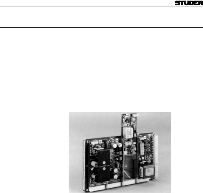
The Euro-card is a convenient circuit board as far as its size and its plug-in features are concerned. However, it often offers excess space for a particular circuit. This has triggered the idea to utilize the Euro-card simply as a carrier (“motherboard”, order no. 1.915.770) for four smaller plug-in circuit boards, the “Modular Sub-Cards” (MSC).
The 32 connections of the Euro-card are divided into 6 supply lines common to the modular sub-cards, and 4 × 6 individual lines joining the plugin sockets for each sub-card. The remaining 2 connections are used as separate bus lines, one of them leading to sub-cards 1 and 2, the other one to sub-cards 3 and 4, resulting in a total of 13 connections to each MSC. A small motherboard for only one MSC is available as well (order no. 1.914.500).
A great variety of different circuits is available in form of MSCs, such as
•Balancing amplifiers
•Microphone pre-amplifiers
•Speaker amplifiers
•0-Ω input amplifiers
•Limiters
•Voltage controlled amplifiers (VCAs)
•Relay sub-cards
•High level input amplifiers
•Line output amplifiers
•1900 Hz signal generator/decoder
•90° filter, stereo/mono
•Flip-flop
•Breadboarding card (0.1”/2.54 mm grid)
To meet the requirements of a system concept, a designer will be able to build individual circuits similar to working with a construction set: He either selects from the available circuits on Euro-cards or makes up his own Euro-card by simply arranging the most suitable combination of Modular Sub-Cards on the motherboard.
E4 |
Date printed: 29.11.01 |
Professional Audio System Components
2.1Modular Sub-Cards (MSCs)
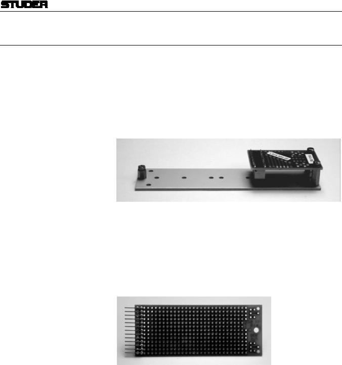
2.1.1 |
Motherboard for 1 MS-Card |
1.914.500 |
If only one MS-card is used, this motherboard is helpful for both mechanical and electrical interfacing. It consists of an aluminium mounting base (135 × 36 mm) and a small PCB with a connector for the MS-card; for wiring, this PCB contains solder terminals.
Note: For installation of up to four MS-cards, there is a second, Euro-card format motherboard available (1.915.770) that can be installed into an Eurocard rack. Please refer to chapter 2.2.1.
Ordering Information |
Motherboard for 1 MS-card |
1.914.500.xx |
2.1.2 |
Breadboarding Card |
1.914.529 |
This experimental board is an empty plug-in PCB compatible with the MSC system. It offers a punched 0.1” grid (2.54 × 2.54 mm) for individual component placement.
Ordering Information: |
Breadboarding card |
1.914.529.xx |
Date printed: 29.11.01 |
E5 |
Professional Audio System Components
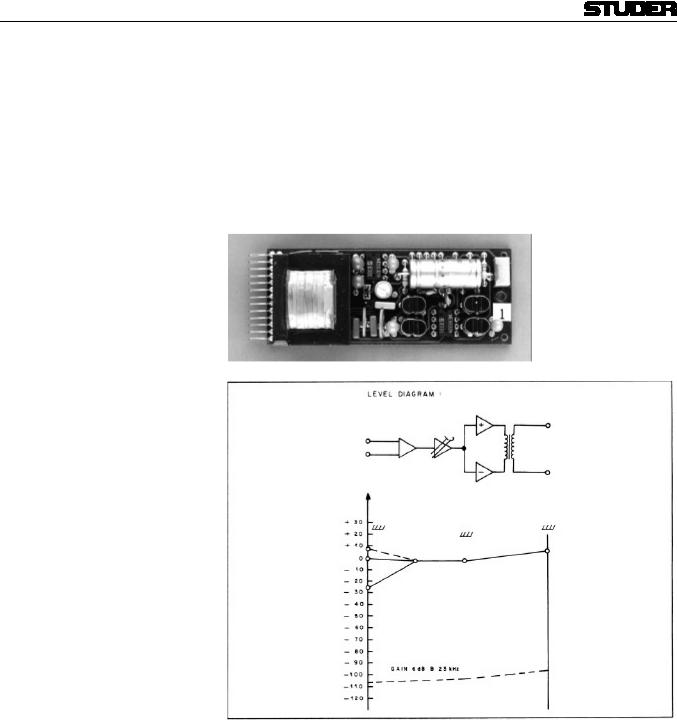
2.1.3 |
Line Output Amplifier |
1.914.501 |
Designed for operation at a nominal line level of +6 dBu (1.55 Vrms), this
amplifier can handle levels of up to +24 dBu (12.3 Vrms), providing an excellent overload margin without the risk of clipping. A unique circuit
around the primary of the amplifier’s output transformer ensures excellent frequency response performance throughout the audible range. Fine and coarse gain adjustment is provided which allows to accommodate input levels in the range from –22...+8 dBu for a nominal +6 dBu output.
E6 |
Date printed: 29.11.01 |

|
|
|
|
|
|
|
|
|
|
|
|
|
|
|
Professional Audio System Components |
|
|
|
|
|
|
|
|
|
|
|
|
|
|
|
|
||
Technical Specifications |
|
|
||||||||||||||
Input: |
|
|
|
|
|
Impedance |
> 10 kΩ, electronically balanced (transformerless) |
|
||||||||
|
|
|
|
|
|
|
|
|
|
|
|
|
|
Overload point |
+24 dBu |
|
Output: |
|
|
|
|
|
Impedance |
< 50 Ω, balanced and floating |
|
||||||||
|
|
|
|
|
|
|
|
|
|
|
|
|
|
Minimum load |
200 Ω |
|
|
|
|
|
|
|
|
|
|
|
|
|
|
|
Maximum level |
+24 dBu |
|
|
|
|
|
|
|
|
|
|
|
|
|
|
|
Gain |
–2 dB...+28 dB; adjustment: coarse 0 or 15 dB/fine –2 dB...+13 dB |
|
|
|
|
|
|
|
|
|
|
|
|
|
|
|
Frequency response |
±0.2 dB, 30 Hz...16 kHz |
|
|
|
|
|
|
|
|
|
|
|
|
|
|
|
THD |
< 0.01%, 30 Hz...16 kHz |
|
|
|
|
|
|
|
|
|
|
|
|
|
|
|
Equivalent input noise |
< –106 dB, linear, at 6 dB gain |
|
Supply: |
|
|
|
|
|
|
±15 V (25 mA idling; max. 170 mA at +24 dBu into 200 Ω) |
|
||||||||
Dimensions: |
MS-card, 34 × 85 mm |
|
||||||||||||||
Ordering Information: |
Line output amplifier |
1.914.501.xx |
||||||||||||||
Date printed: 29.11.01 |
E7 |


Professional Audio System Components
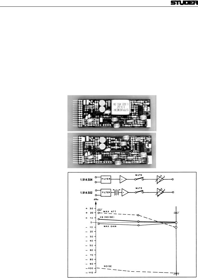
2.1.4 |
High-Level Input Amplifier |
1.914.502/504 |
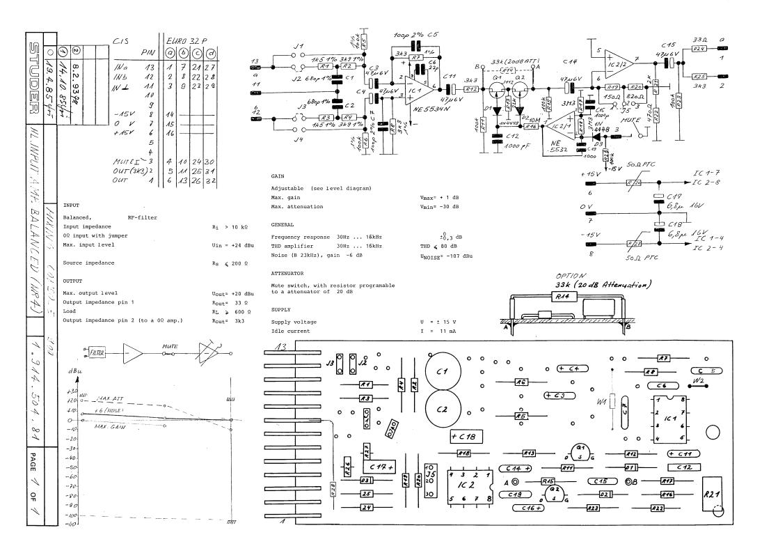
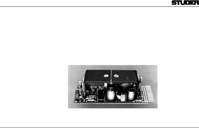
Basically, this is an amplifier with near 0 dB gain for high-level applications, yet with additional features, such as remote muting facility, RF input filter, and choice of two input and output impedances. The input configuration is balanced, whereas the output is unbalanced. Jumpers in the primary of the input circuit permit selection of either high-impedance operation with RF filter or a 0-Ω input without filter, for summing-bus applications. The combining (mixing) resistors have to be added externally. By switching pin3 of the amplifier’s 13-pin plug to ground (via a corresponding connection on the motherboard) the amplifier may be muted from a remote point. If only 20 dB level reduction is desirable instead of muting, this can be programmed by connecting a resistor across two solder points.
E8 |
Date printed: 29.11.01 |

Professional Audio System Components
The amplifier may be used, for example, to work into a 600 Ω load, or
|
|
into the input of a 0-Ω input amplifier of another summing circuit. |
|
|
|
If transformerless yet balanced input configuration is desired, an MSC |
|
|
|
amplifier with basically the same performance characteristics is available |
|
|
|
as well. Refer to the ordering information below. |
|
Technical Specifications |
|
|
|
Input: |
Impedance |
> 10 kΩ (transformeror electronically balanced versions available; input |
|
|
|
with RF filter; 0-Ω input selectable with jumpers) |
|
|
Common mode rejection |
> 50 dB |
|
|
Overload point |
+24 dBu (12.3 Vrms) |
|
Output: |
Impedance |
33 Ω (pin1), unbalanced |
|
|
Minimum load |
600 Ω |
|
|
Maximum level |
+20 dBu (7.75 Vrms) |
|
|
Impedance |
3.3 kΩ (pin2), unbalanced, for 0-Ω operation |
|
|
Maximum gain |
1 dB |
|
|
Maximum attenuation |
30 dB |
|
|
Frequency response |
±0.3 dB, 30 Hz...16 kHz |
|
|
THD |
< 0.03%, 30 Hz...16 kHz |
|
|
Equivalent input noise |
–100 dBu, unweighted, at 6 dB attenuation |
|
|
Programmable attenuation |
20 dB (resistor 33 kΩ across muting circuit) |
|
Supply: |
|
±15 V (11 mA idling) |
|
Dimensions: |
MS-card, 34 × 85 mm |
|
|
Ordering Information: |
High level input amp with transformer-balanced input |
1.914.502.xx |
|
|
|
High level input amp with electronically balanced input |
1.914.504.xx |
Date printed: 29.11.01 |
E9 |


Studer Audio Components
HL Input Amp, transformer-balanced 1.914.502.81 ( 1)
Page: 1 of 1
Idx. |
Pos. |
Part No. |
Qty. |
Type/Val. |
Description |
|
|
Idx. Pos. |
Part No. |
Qty. |
Type/Val. |
Description |
|
0 |
C 1 |
59.05.1681 |
|
680p |
PP, 1%, 630V |
|
|
|
|
||||
0 |
C 2 |
59.05.1681 |
|
680p |
PP, 1%, 630V |
|
|
|
|
||||
0 |
C 3 |
59.06.5682 |
|
6n8 |
PETP, 63V, |
5%, RM5 |
|
|
|
|
|||
0 |
C 5 |
59.34.5391 |
|
390p |
CER 63V, 5%, N1500 |
|
|
|
|
||||
0 |
C 6 |
59.34.2220 |
|
22p |
CER 63V, 5%, N150 |
|
|
|
|
||||
0 |
C 11 |
59.26.0470 |
|
47u |
SAL 6.3V 20% |
|
|
|
|
||||
0 |
C 12 |
59.32.4102 |
|
1n0 |
CER 20%, 50V |
|
|
|
|
||||
0 |
C 13 |
not used |
|
1n0 |
PETP, 63V, 10%, RM5 |
|
|
|
|
||||
0 |
C 14 |
59.26.0470 |
|
47u |
SAL 6.3V 20% |
|
|
|
|
||||
0 |
C 15 |
59.06.0102 |
|
1n0 |
PETP, 63V, 10%, RM5 |
|
|
|
|
||||
0 |
C 16 |
59.26.0470 |
|
47u |
SAL 6.3V 20% |
|
|
|
|
||||
0 |
C 17 |
59.26.2689 |
|
6u8 |
SAL 16V 20% |
|
|
|
|
||||
0 |
C 18 |
59.26.2689 |
|
6u8 |
SAL 16V 20% |
|
|
|
|
||||
0 |
C 19 |
59.06.0102 |
|
1n0 |
PETP, 63V, 10%, RM5 |
|
|
|
|
||||
0 |
D 1 |
50.04.0125 |
|
1N4448 |
75V, 150mA, 4ns, DO-35 |
|
|
|
|
||||
0 |
D 2 |
50.04.0125 |
|
1N4448 |
75V, 150mA, 4ns, DO-35 |
|
|
|
|
||||
0 |
D 3 |
50.04.0125 |
|
1N4448 |
75V, 150mA, 4ns, DO-35 |
|
|
|
|
||||
0 |
IC 1 |
50.05.0244 |
|
5534A |
Single Op-amp, low noise |
|
|
|
|
||||
0 |
IC 2 |
50.09.0106 |
|
5532A |
Dual Op-Amp, low noise |
|
|
|
|
||||
0 |
J 1 |
54.01.0021 |
|
Jumper |
0.63*0.63mm, Au |
|
|
|
|
||||
0 |
J 2 |
54.01.0021 |
|
Jumper |
0.63*0.63mm, Au |
|
|
|
|
||||
0 |
J 3 |
54.01.0021 |
|
Jumper |
0.63*0.63mm, Au |
|
|
|
|
||||
0 |
P 1 |
54.01.0273 |
|
13p |
Stecker CIS |
parallelsteck |
|
|
|
|
|||
0 |
P 2 |
54.01.0020 11 pcs |
1p |
Pin, 1reihig, gerade |
|
|
|
|
|||||
0 |
Q 1 |
50.03.0350 |
|
J112 |
JFET N-Channel |
|
|
|
|
||||
0 |
Q 2 |
50.03.0350 |
|
J112 |
JFET N-Channel |
|
|
|
|
||||
0 |
R 1 |
57.11.3152 |
|
1k5 |
MF, 1%, 0207 |
|
|
|
|
||||
0 |
R 2 |
57.11.3392 |
|
3k9 |
MF, 1%, 0207 |
|
|
|
|
||||
0 |
R 3 |
57.11.3152 |
|
1k5 |
MF, 1%, 0207 |
|
|
|
|
||||
0 |
R 4 |
57.11.3392 |
|
3k9 |
MF, 1%, 0207 |
|
|
|
|
||||
0 |
R 5 |
57.11.3392 |
|
3k9 |
MF, 1%, 0207 |
|
|
|
|
||||
0 |
R 6 |
57.11.3472 |
|
4k7 |
MF, 1%, 0207 |
|
|
|
|
||||
0 |
R 7 |
57.11.3432 |
|
4k3 |
MF, 1%, 0207 |
|
|
|
|
||||
0 |
R 8 |
57.11.3101 |
|
100R |
MF, 1%, 0207 |
|
|
|
|
||||
0 |
R 11 |
57.11.3104 |
|
100k |
MF, 1%, 0207 |
|
|
|
|
||||
0 |
R 12 |
57.11.3332 |
|
3k3 |
MF, 1%, 0207 |
|
|
|
|
||||
0 |
R 13 |
57.11.3223 |
|
22k |
MF, 1%, 0207 |
|
|
|
|
||||
0 |
R 14 |
not used |
|
33k |
MF, 1%, 0207 |
|
|
|
|
||||
|
|
|
|
optional (20 dB attenuation) |
|
|
|
|
|
|
|
|
|
0 |
R 15 |
57.11.3104 |
|
100k |
MF, 1%, 0207 |
|
|
|
|
||||
0 |
R 16 |
57.11.5106 |
|
10M |
MF, 5%, 0207 |
|
|
|
|
||||
0 |
R 17 |
57.11.5335 |
|
3M3 |
MF, 5%, 0207 |
|
|
|
|
||||
0 |
R 18 |
57.11.5335 |
|
3M3 |
MF, 5%, 0207 |
|
|
|
|
||||
0 |
R 19 |
57.11.3151 |
|
150R |
MF, 1%, 0207 |
|
|
|
|
||||
0 |
R 20 |
57.11.3821 |
|
820R |
MF, 1%, 0207 |
|
|
|
|
||||
0 |
R 21 |
58.01.9202 |
|
2k0 |
Cermet, 10%, 0.5W, vertical |
|
|
|
|
||||
0 |
R 22 |
57.11.3561 |
|
560R |
MF, 1%, 0207 |
|
|
|
|
||||
0 |
R 23 |
57.11.3104 |
|
100k |
MF, 1%, 0207 |
|
|
|
|
||||
0 |
R 24 |
57.11.3330 |
|
33R |
MF, 1%, 0207 |
|
|
|
|
||||
0 |
R 25 |
57.11.3332 |
|
3k3 |
MF, 1%, 0207 |
|
|
|
|
||||
0 |
R 26 |
57.99.0206 |
|
50R |
PTC, 25V, 0.5W |
|
|
|
|
||||
0 |
R 27 |
57.99.0206 |
|
50R |
PTC, 25V, 0.5W |
|
|
|
|
||||
0 |
R 28 |
57.11.3104 |
|
100k |
MF, 1%, 0207 |
|
|
|
|
||||
0 |
T 1 |
1.022.451.00 |
|
1:0.62 |
EINGANGSTRAFO 1 : 0,62 |
|
|
|
|
||||
1 |
W 1 |
57.11.3000 |
|
0R0 |
MF, |
0207 |
|
|
|
|
|
|
|
1 |
W 2 |
64.01.0106 |
|
0.6mm |
Schaltdraht Cu |
|
|
|
|
||||
End of List
Comments:
(01) W1, W2 added
Date printed: 06.11.2006

Studer Audio Components
HL Input Amp, electronically balanced 1.914.504.81 ( 1)
Page: 1 of 1
Idx. |
Pos. |
Part No. |
Qty. |
Type/Val. |
Description |
|
|
Idx. Pos. |
Part No. |
Qty. |
Type/Val. |
Description |
|
0 |
C 1 |
59.05.1681 |
|
680p |
PP, 1%, 630V |
|
|
|
|
||||
0 |
C 2 |
59.05.1681 |
|
680p |
PP, 1%, 630V |
|
|
|
|
||||
0 |
C 3 |
59.26.0470 |
|
47u |
SAL 6.3V 20% |
|
|
|
|
||||
0 |
C 4 |
59.26.0470 |
|
47u |
SAL 6.3V 20% |
|
|
|
|
||||
0 |
C 5 |
59.34.2101 |
|
100p |
CER 63V, 5%, N150 |
|
|
|
|
||||
0 |
C 6 |
59.34.2220 |
|
22p |
CER 63V, 5%, N150 |
|
|
|
|
||||
0 |
C 7 |
59.34.2101 |
|
100p |
CER 63V, 5%, N150 |
|
|
|
|
||||
0 |
C 11 |
59.26.0470 |
|
47u |
SAL 6.3V 20% |
|
|
|
|
||||
0 |
C 12 |
59.32.4102 |
|
1n0 |
CER 20%, 50V |
|
|
|
|
||||
0 |
C 14 |
59.26.0470 |
|
47u |
SAL 6.3V 20% |
|
|
|
|
||||
0 |
C 15 |
59.06.0102 |
|
1n0 |
PETP, 63V, 10%, RM5 |
|
|
|
|
||||
0 |
C 16 |
59.26.0470 |
|
47u |
SAL 6.3V 20% |
|
|
|
|
||||
0 |
C 17 |
59.26.2689 |
|
6u8 |
SAL 16V 20% |
|
|
|
|
||||
0 |
C 18 |
59.26.2689 |
|
6u8 |
SAL 16V 20% |
|
|
|
|
||||
0 |
C 19 |
59.06.0102 |
|
1n0 |
PETP, 63V, 10%, RM5 |
|
|
|
|
||||
0 |
D 1 |
50.04.0125 |
|
1N4448 |
75V, 150mA, 4ns, DO-35 |
|
|
|
|
||||
0 |
D 2 |
50.04.0125 |
|
1N4448 |
75V, 150mA, 4ns, DO-35 |
|
|
|
|
||||
0 |
D 3 |
50.04.0125 |
|
1N4448 |
75V, 150mA, 4ns, DO-35 |
|
|
|
|
||||
0 |
IC 1 |
50.05.0244 |
|
5534A |
Single Op-amp, low noise |
|
|
|
|
||||
0 |
IC 2 |
50.09.0106 |
|
5532A |
Dual Op-Amp, low noise |
|
|
|
|
||||
0 |
J 1 |
54.01.0021 |
|
Jumper |
0.63*0.63mm, Au |
|
|
|
|
||||
0 |
J 2 |
54.01.0021 |
|
Jumper |
0.63*0.63mm, Au |
|
|
|
|
||||
0 |
J 3 |
54.01.0021 |
|
Jumper |
0.63*0.63mm, Au |
|
|
|
|
||||
0 |
P 1 |
54.01.0273 |
|
13p |
Stecker CIS |
parallelsteck |
|
|
|
|
|||
0 |
P 2 |
54.01.0020 9 pcs |
1p |
Pin, 1reihig, gerade |
|
|
|
|
|||||
0 |
Q 1 |
50.03.0350 |
|
J112 |
JFET N-Channel |
|
|
|
|
||||
0 |
Q 2 |
50.03.0350 |
|
J112 |
JFET N-Channel |
|
|
|
|
||||
0 |
R 1 |
57.11.3152 |
|
1k5 |
MF, 1%, 0207 |
|
|
|
|
||||
0 |
R 2 |
57.11.3392 |
|
3k9 |
MF, 1%, 0207 |
|
|
|
|
||||
0 |
R 3 |
57.11.3152 |
|
1k5 |
MF, 1%, 0207 |
|
|
|
|
||||
0 |
R 4 |
57.11.3392 |
|
3k9 |
MF, 1%, 0207 |
|
|
|
|
||||
0 |
R 5 |
57.11.3104 |
|
100k |
MF, 1%, 0207 |
|
|
|
|
||||
0 |
R 6 |
57.11.3104 |
|
100k |
MF, 1%, 0207 |
|
|
|
|
||||
0 |
R 7 |
57.11.3332 |
|
3k3 |
MF, 1%, 0207 |
|
|
|
|
||||
0 |
R 8 |
57.11.3332 |
|
3k3 |
MF, 1%, 0207 |
|
|
|
|
||||
0 |
R 11 |
57.11.3104 |
|
100k |
MF, 1%, 0207 |
|
|
|
|
||||
0 |
R 12 |
57.11.3332 |
|
3k3 |
MF, 1%, 0207 |
|
|
|
|
||||
0 |
R 13 |
57.11.3223 |
|
22k |
MF, 1%, 0207 |
|
|
|
|
||||
0 |
R 14 |
not used |
|
33k |
MF, 1%, 0207 |
|
|
|
|
||||
|
|
|
|
optional (20 dB attenuation) |
|
|
|
|
|
|
|
|
|
0 |
R 15 |
57.11.3104 |
|
100k |
MF, 1%, 0207 |
|
|
|
|
||||
0 |
R 16 |
57.11.5106 |
|
10M |
MF, 5%, 0207 |
|
|
|
|
||||
0 |
R 17 |
57.11.5335 |
|
3M3 |
MF, 5%, 0207 |
|
|
|
|
||||
0 |
R 18 |
57.11.5335 |
|
3M3 |
MF, 5%, 0207 |
|
|
|
|
||||
0 |
R 19 |
57.11.3151 |
|
150R |
MF, 1%, 0207 |
|
|
|
|
||||
0 |
R 20 |
57.11.3821 |
|
820R |
MF, 1%, 0207 |
|
|
|
|
||||
0 |
R 21 |
58.01.9202 |
|
2k0 |
Cermet, 10%, 0.5W, vertical |
|
|
|
|
||||
0 |
R 22 |
57.11.3471 |
|
470R |
MF, 1%, 0207 |
|
|
|
|
||||
0 |
R 23 |
57.11.3104 |
|
100k |
MF, 1%, 0207 |
|
|
|
|
||||
0 |
R 24 |
57.11.3330 |
|
33R |
MF, 1%, 0207 |
|
|
|
|
||||
0 |
R 25 |
57.11.3332 |
|
3k3 |
MF, 1%, 0207 |
|
|
|
|
||||
0 |
R 26 |
57.99.0206 |
|
50R |
PTC, 25V, 0.5W |
|
|
|
|
||||
0 |
R 27 |
57.99.0206 |
|
50R |
PTC, 25V, 0.5W |
|
|
|
|
||||
1 |
R 28 |
57.11.3104 |
|
100k |
MF, 1%, 0207 |
|
|
|
|
||||
1 |
W 1 |
57.11.3000 |
|
0R0 |
MF, |
0207 |
|
|
|
|
|
|
|
1 |
W 2 |
64.01.0106 |
|
0.6mm |
Schaltdraht Cu |
|
|
|
|
||||
End of List
Comments:
(01) R28, W1, W2 added
Date printed: 06.11.2006
Professional Audio System Components
2.1.5 |
Loudspeaker Amplifier |
1.914.505 |
This low-power amplifier on a modular sub-card is designed to drive a 10...15 Ω speaker. Power output is about 2...3 W. As can be concluded from this specification, the amplifier is not intended for high-quality monitoring. It will be ideally suited, however, for pre-fader listening and similar applications. The amplifier’s input is balanced and floating, with adjustable gain.
Technical Specifications
Input impedance |
> 10 kΩ, balanced and floating (with transformer) |
|
Nominal power output |
2 W into 15 Ω |
|
Power output |
25 mW...2.5 W into 15 Ω, with 0 dBu input |
|
Distortion |
< 0.5% at 2 W |
|
|
< 0.15% at 500 mW |
|
S/N |
99 dB, ref. to 2 W at max. gain |
|
Frequency response |
–0.5 dB at 15 kHz |
|
High pass filter |
150 Hz, 12 dB/oct. |
|
Supply: |
–24 V (40 mA idling, max. 220 mA fully driven) |
|
Dimensions: |
MS-card, 34 × 85 mm |
|
Ordering Information: |
Loudspeaker amplifier |
1.914.505.xx |
E10 |
Date printed: 29.11.01 |


Professional Audio System Components
2.1.6 |
Microphone Pre-Amplifiers |
1.914.506/507 |
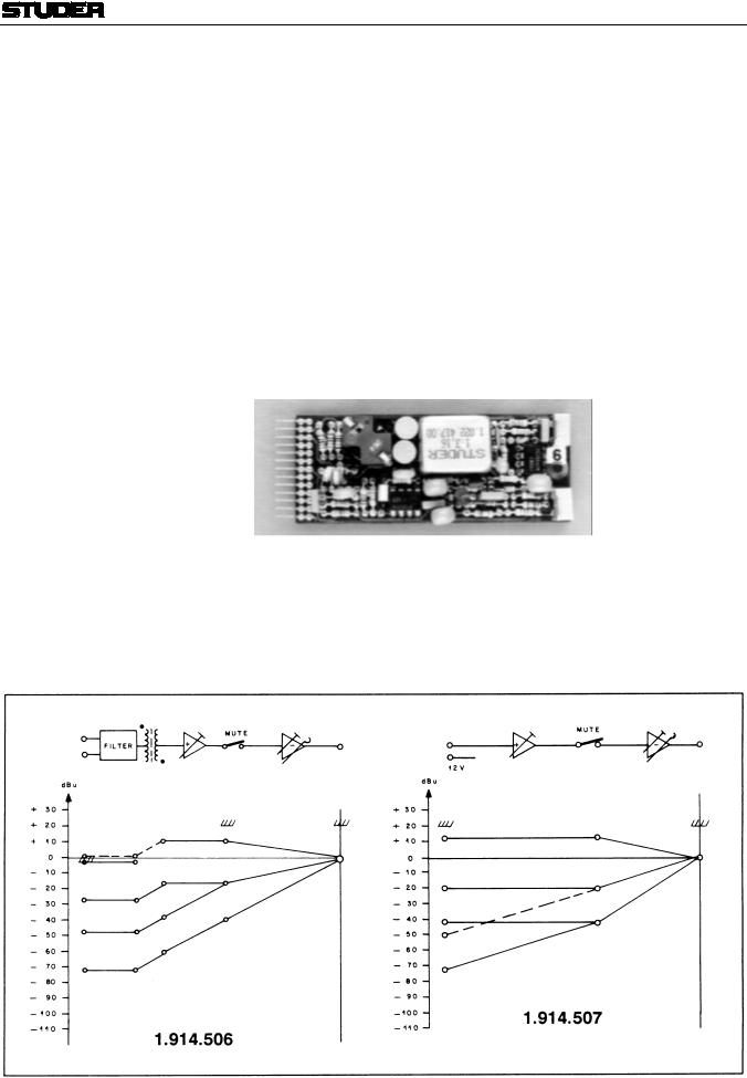
Two different microphone pre-amplifiers are available, for dynamic or condenser microphones, and for electret microphones. Both offer high gain and low noise, as is required for microphone pre-amplification.
1.914.506 features a balanced and floating input. It is designed for dynamic or condenser microphones with a source impedance of 200 Ω or less. An RF filter is incorporated at the input transformer’s primary. Furthermore, the input is equipped with the resistors required for phantom powering of condenser microphones.
1.914.507 is designed for unbalanced electret microphones requiring a 12 V supply.
A wide range of input levels can be accommodated (see level diagram).
By using the same solid-state switching circuit as can be found in the line and high-level amplifiers, remote muting or activation of a fixed amount of attenuation are possible as well.
The amplifier’s two outputs are unbalanced, with impedances of 3.3 kΩ or 33 Ω, respectively.
Date printed: 29.11.01 |
E11 |

Professional Audio System Components
Technical Specifications
Input: |
|
Transformer-balanced and floating, with RF filter |
(1.914.506) |
|
|
Unbalanced, with RF filter and electret supply |
(1.914.507) |
Impedance |
> 1 kΩ, for microphones with an impedance of 200 Ω or less. |
|
|
Max. input level |
–2 dBu (615 mVrms); THD at 30 Hz: approx. 1% |
|
|
Common mode rejection |
> 60 dB, unbalanced, to ground |
|
|
Output: |
Max. level |
+20 dBu (7.75 Vrms) |
|
Nominal level |
0 dBu (0.775 Vrms) |
|
|
Impedance |
33 Ω (pin1) |
|
|
|
|
3.3 kΩ (pin2; to a 0-Ω amp.) |
|
Minimum load |
600 Ω |
|
|
|
Max. gain |
71 dB (see level diagram) |
|
Frequency response |
±0.5 dB, 30 Hz...16 kHz |
|
|
|
THD |
< 0.3%, 30 Hz...16 kHz at 20 dB gain |
|
Noise figure, linear |
< 4.5 dB, input terminated with 200 Ω |
|
|
Supply: |
|
±15 V (11 mA idling) |
|
|
|
+48 V (1.914.506, only if phantom powering required) |
|
Dimensions: |
|
MS-card, 34 × 85 mm |
|
Ordering Information: |
• |
Microphone pre-amplifier for dynamic microphones |
1.914.506.xx |
|
• |
Microphone pre-amplifier for electret microphones |
1.914.507.xx |
E12 |
Date printed: 29.11.01 |


Professional Audio System Components
2.1.7 |
VCA with Electronically Balanced Connections |
1.914.515 |
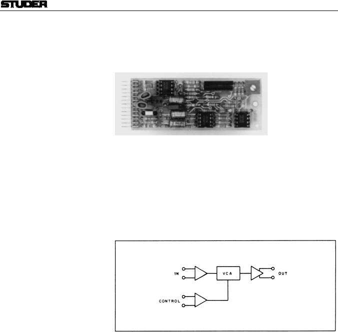
In contrast to the VCA 1.914.518/528 (chapter 2.1.8), this assembly features an electronically balanced input and output.
It is intended for use in balanced audio systems for a variety of applications, especially when gain is to be controlled from a remote point. It will be useful in audio-video post-production work where suitable DC ramps can control cross-fades, voice-overs, etc. Its high overload margin and its exceptionally low noise and distortion performance make it the perfect choice for high-quality audio applications.
By connecting the gain control terminals of a number of VCAs to a common potentiometer or fader, several audio channels may thus be controlled simultaneously.
Two control inputs provide VCA gain control from two different remote points
Date printed: 29.11.01 |
E13 |

Professional Audio System Components
Technical Specifications
Input: |
Impedance |
³ 10 kW, electronically balanced |
|
|
Clipping point |
+24 dBu |
|
Output: |
|
Electronically balanced |
|
|
Recommended load |
³ 2 kW |
|
|
Maximum level |
+24 dBu |
|
|
Frequency response |
–0.5 dB, 30 Hz...15 kHz |
|
|
Gain/attenuation range |
+40...–100 dB, with ext. control |
|
Control input: pin1; gain tracking |
0 V = unity gain; |
|
|
|
|
1 dB/µA; jumper 1-2 |
|
|
|
20 dB/V; jumper 2-3 |
|
|
|
10 dB/V; jumper 3-4 |
|
Control input: pin10; gain tracking |
10 dB/V |
|
|
|
THD |
< 0.1% |
|
|
Equivalent input noise |
–93 dBu @ unity gain |
|
Supply: |
|
±15 V (25 mA) |
|
Dimensions: |
MS-card, 34 × 85 mm |
|
|
Ordering Information: |
VCA with electronically balanced input and output |
1.914.515.xx |
|
E14 |
Date printed: 29.11.01 |


Professional Audio System Components
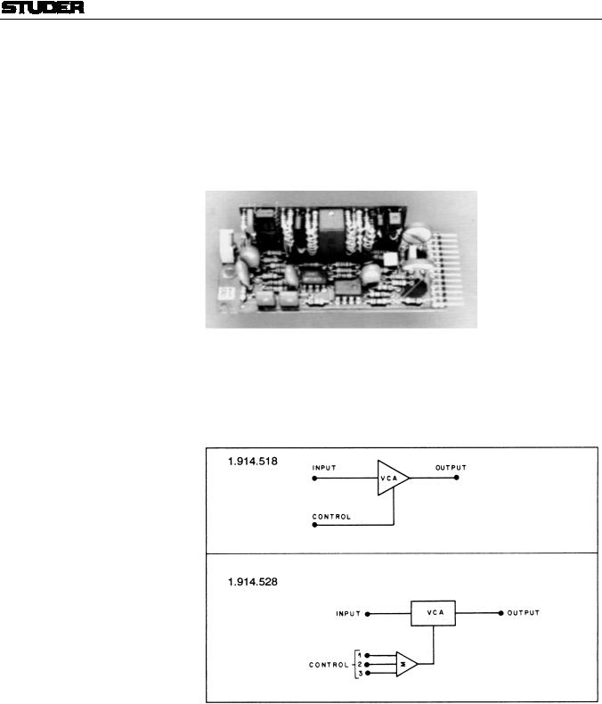
2.1.8 |
VCA with 1 or 3 Control Ports |
1.914.518/528 |
Within the range of modular sub-cards, two more VCAs are available. Voltage controlled amplifiers are ideally suited for applications such as remote level control, level limiting (in combination with the voltage processor 1.914.519) or for automatic “voice-over” circuits, when driven by suitable ramp generators. These VCAs offer outstandingly low noise and harmonic distortion.
For best performance, they should be operated at a level of 0 dBu.
Gain pre-selection is possible on the 1.914.518 version, allowing gain/attenuation ranges either from +10 to –90 dB or from +40 to –70 dB, using an external potentiometer.
The 1.914.528 VCA card differs in that it is equipped with three external control inputs, providing gain control from three different locations.
Date printed: 29.11.01 |
E15 |

Professional Audio System Components
Technical Specifications
Input: |
Impedance |
> 3 kW |
|
|
Clipping point |
+20 dBu |
|
Output: |
Impedance |
33 W or 3.3 kW, selectable |
|
|
Max. level |
+20 dBu |
|
|
Recommended load |
³ 2 kW |
|
|
Frequency response |
–0.5 dB, 30 Hz...16 kHz |
|
|
External gain control |
+40...–90 dB (1.914.518.xx) |
|
|
|
+40...–100 dB (1.914.528.xx) |
|
Gain/attenuation range (pot. meter) |
+40...–60 dB / +10...–70 dB / +10...–90 dB (1.914.518.xx only, jumper- |
||
|
|
selectable) |
|
|
Gain tracking |
10 dB/V |
|
|
THD |
< 0.1% |
|
|
Equivalent input noise |
–102 dBu |
|
Supply: |
|
±15 V (40 mA) |
|
Dimensions: |
MS-card, 34 × 85 mm |
|
|
Ordering Information: |
Voltage controlled amplifier with 1 control port |
1.914.518.xx |
|
|
|
Voltage controlled amplifier with 3 control ports |
1.914.528.xx |
E16 |
Date printed: 29.11.01 |

 Loading...