


Professional Audio System Components
Technical Specifications
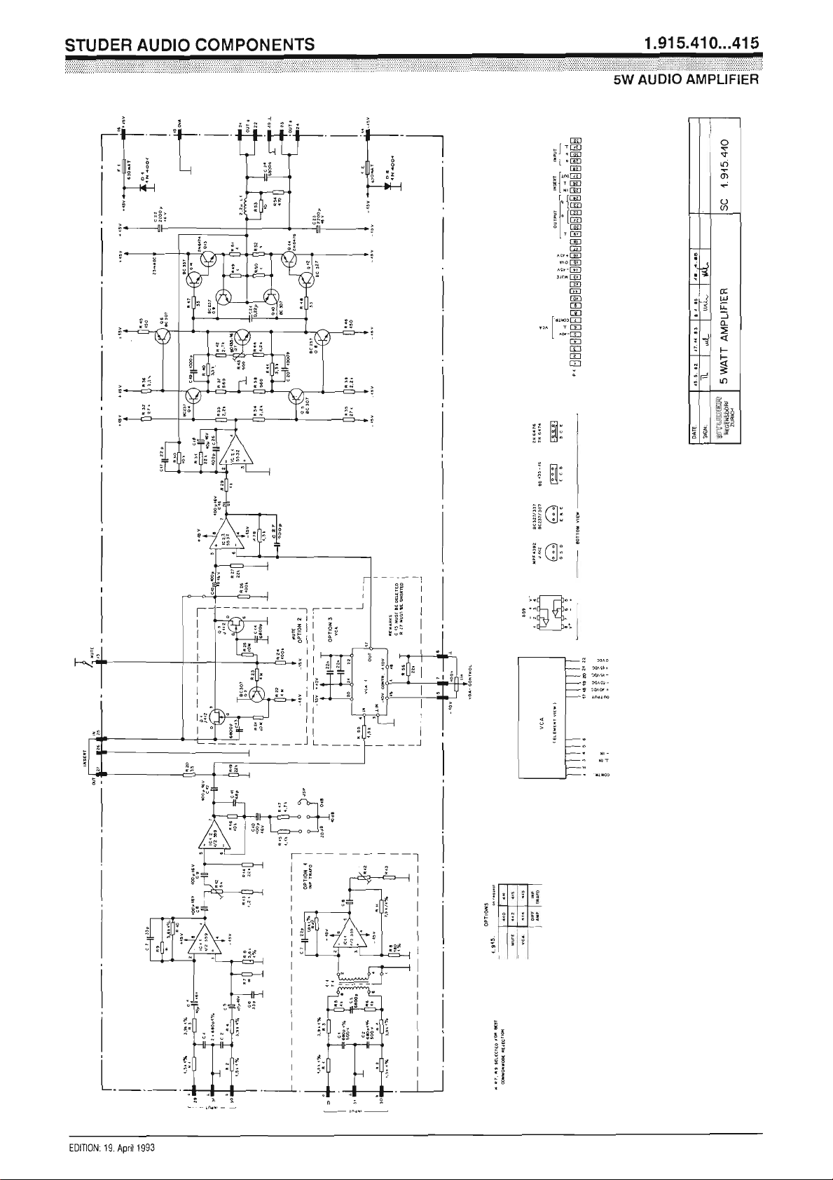
Audio: Power output 4 W/15 Ω
5 W/8 Ω
2.5 W/4 Ω, continuous, sine wave
THD < 0.1% @ rated output, 30 Hz...16 kHz
Frequency response ±0.5 dB, 30 Hz...16 kHz
Input impedance 10 kΩ, balanced
Sensitivity –17...+16 dBu (0.11...4.9 V
Maximum input level +24 dBu (12.3 V
) clipping point
rms
S/N 100 dB, linear to 23 kHz at normal operating gain (input +6 dBu)
85 dB, at maximum gain
Supply: ±15 V DC (40 mA idling; 400 mA @ 5 W/8 Ω)
Output stage quiescent current 23 mA
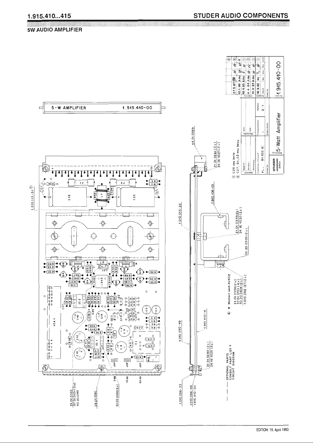
Dimensions: Euro-card 100 × 160 mm, 7M units wide
Weight approx. 210 g
) for rated output
rms
Ordering Information:
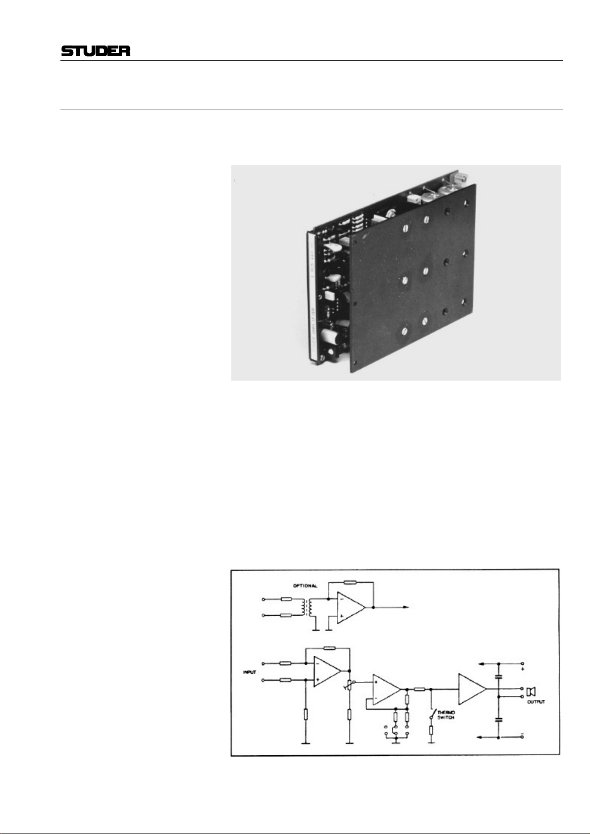
5 W amplifier with • transformerless input 1.915.410.xx
• input transformer 1.915.411.xx
• transformerless input and remote muting facility 1.915.412.xx
• input transformer and remote muting facility 1.915.413.xx
• transformerless input and remote gain control (VCA) 1.915.414.xx
• input transformer and remote gain control (VCA) 1.915.415.xx
E42 Date printed: 29.11.01
Professional Audio System Components
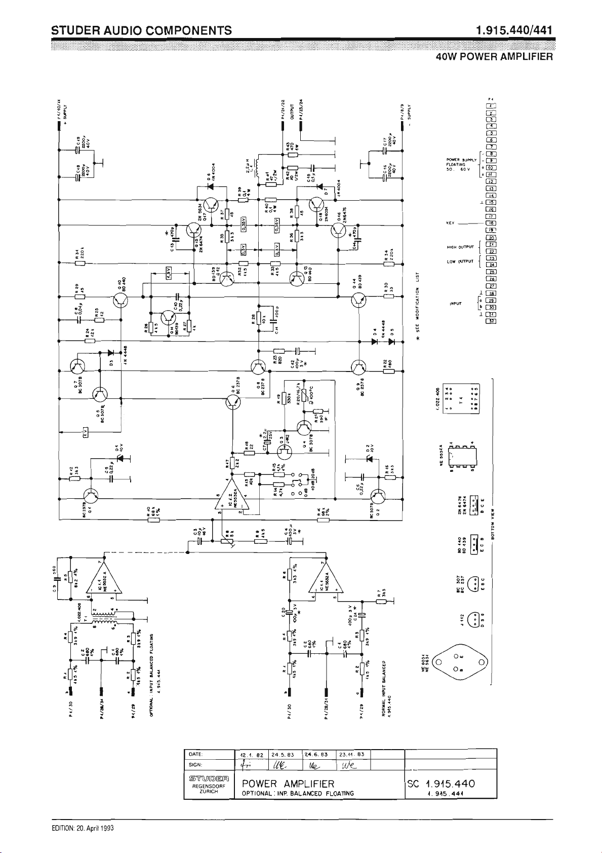
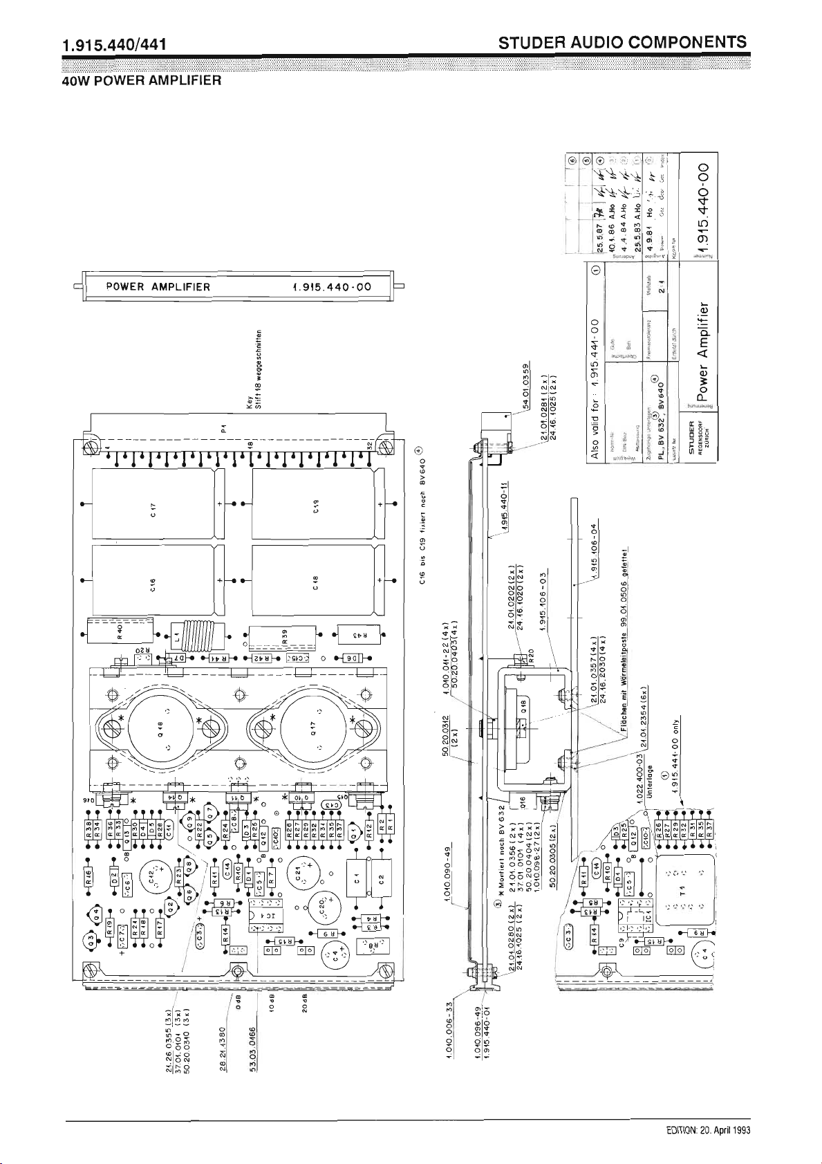
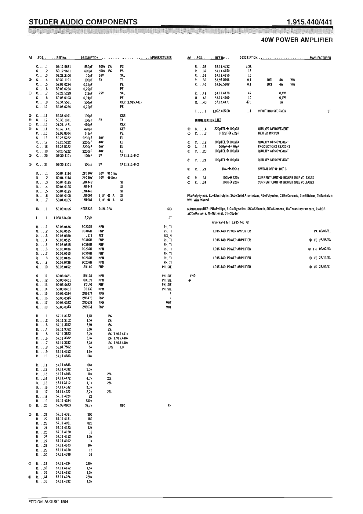
2.2.7 40 W Power Amplifier 1.915.440/441
For applications where higher power level is needed, a 40 W amplifier has
been realized on a Euro-card. Its width is 32 mm, which equals 7M widths
approximately.
Power is supplied from a separate 45 VDC source, as is contained in the
19” mounting frame 1.918.120.xx. Two amplifier cards will fit into that
frame, making it suitable for applications where stereophonic monitoring
is required.
Special Features • Transformerless version with electronically balanced inputs standard
• Version with balanced and floating inputs available
• Output stage protected from overload by momentary power limiting
• Temperature sensing avoids thermal overload
• High-end frequency response limited to prevent transient intermodulation
distortion
• Low distortion performance, even at low power output
• Operation with output transformer possible
Date printed: 29.11.01 E43

Professional Audio System Components
Technical Specifications
Audio: Power output 40 W/4 Ω, continuous, sine-wave,
THD < 0.1 %, 30 Hz...15 kHz (up to rated output)
Output impedance 0.1 Ω
Input impedance 10 kΩ
Common mode rejection > 50 dB, 30 Hz...16 kHz (with input transformer)
Input sensitivity –12...+18 dBu (0.195...6.2 V
in three 10 dB-increments, plus fine-trim range of 12 dB)
Frequency response +0.5/–1 dB, 30 Hz...15 kHz
S/N 105 dB @ maximum gain
90 dB @ minimum gain
) for rated output (adjustable with jumper
rms
Supply: 45 V
(70 mA idling, 1.5 A @ 40 W/4 Ω)
DC
Dimensions: Euro-card 100 × 160 mm, 7M units wide
Ordering Information:
Euro-cards • 40 W power amplifier with transformerless input 1.915.440.xx
• 40 W power amplifier with input transformer 1.915.441.xx
19”/1U standard products
40 W power amplifier • Mono version, 19”/1U 75.700.80311
• Stereo version, 19”/1U 75.700.80322
• 19”/1U mounting frame (without amplifier cards) 1.918.120.xx
E44 Date printed: 29.11.01
Professional Audio System Components
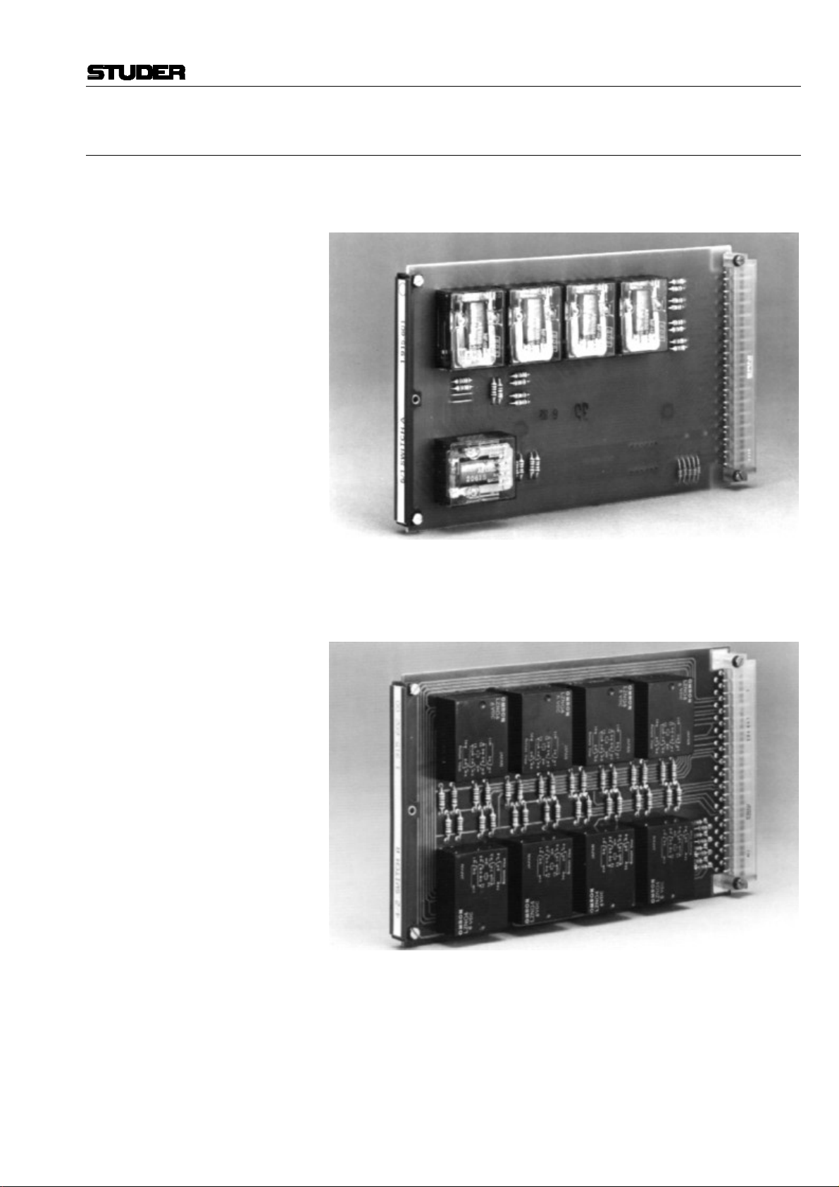
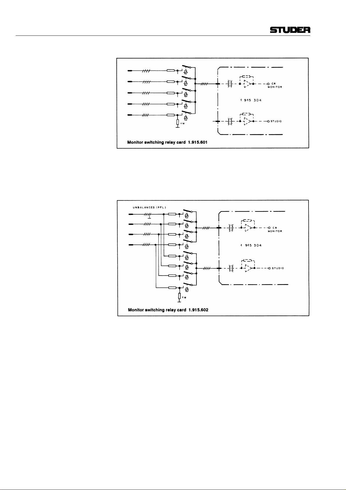
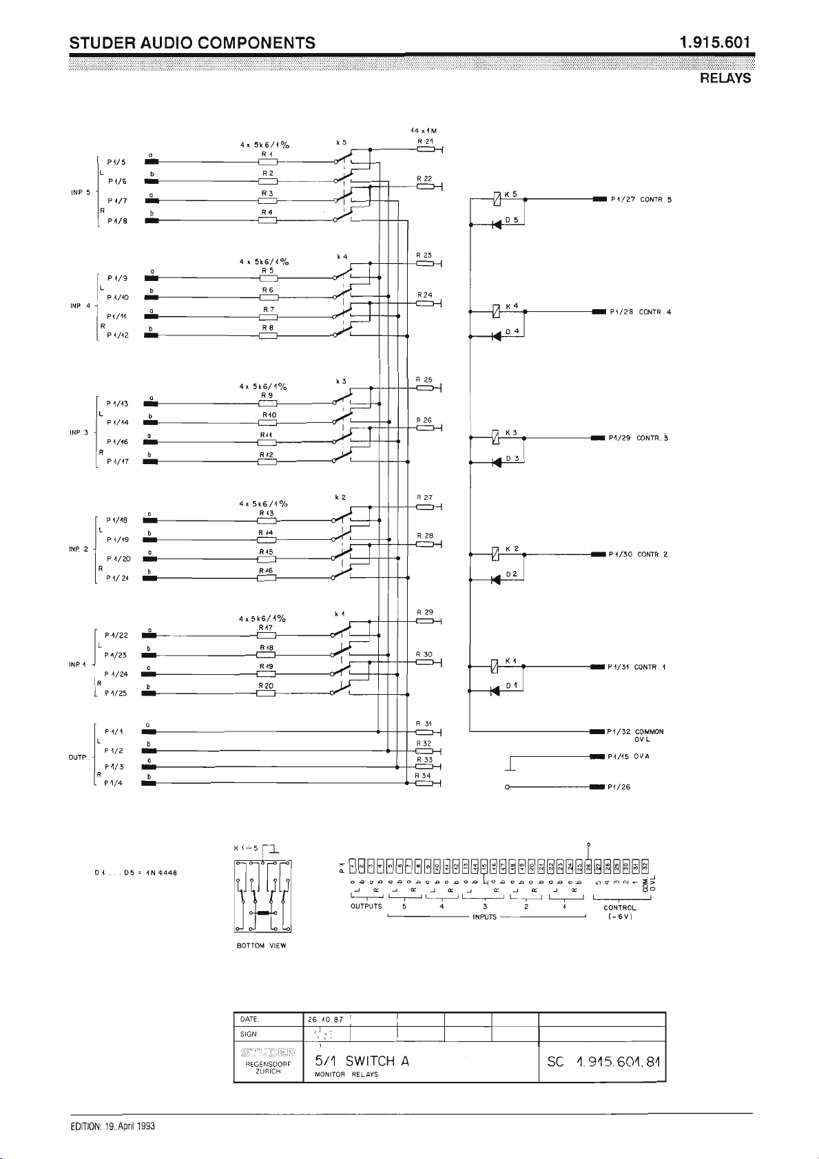
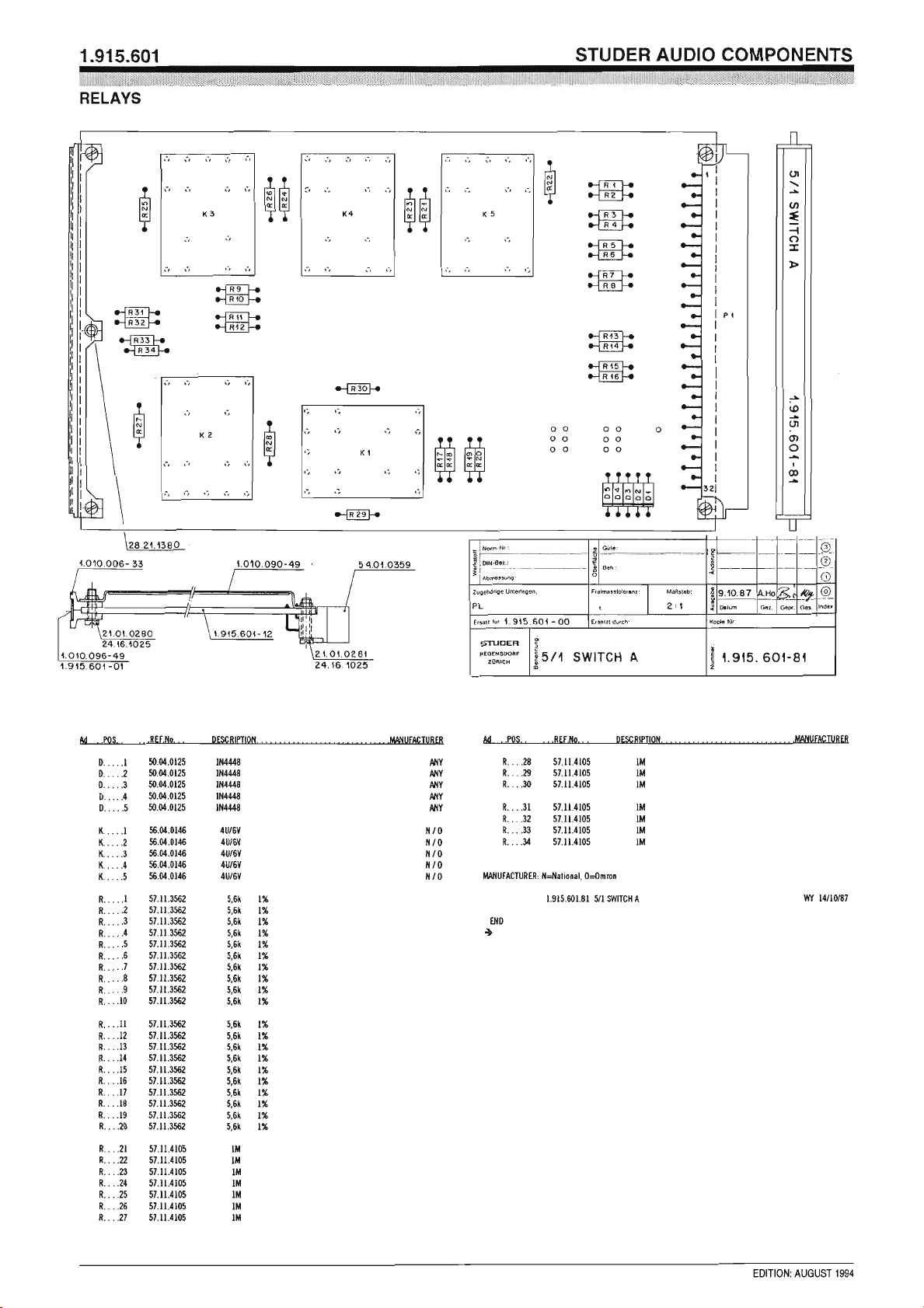
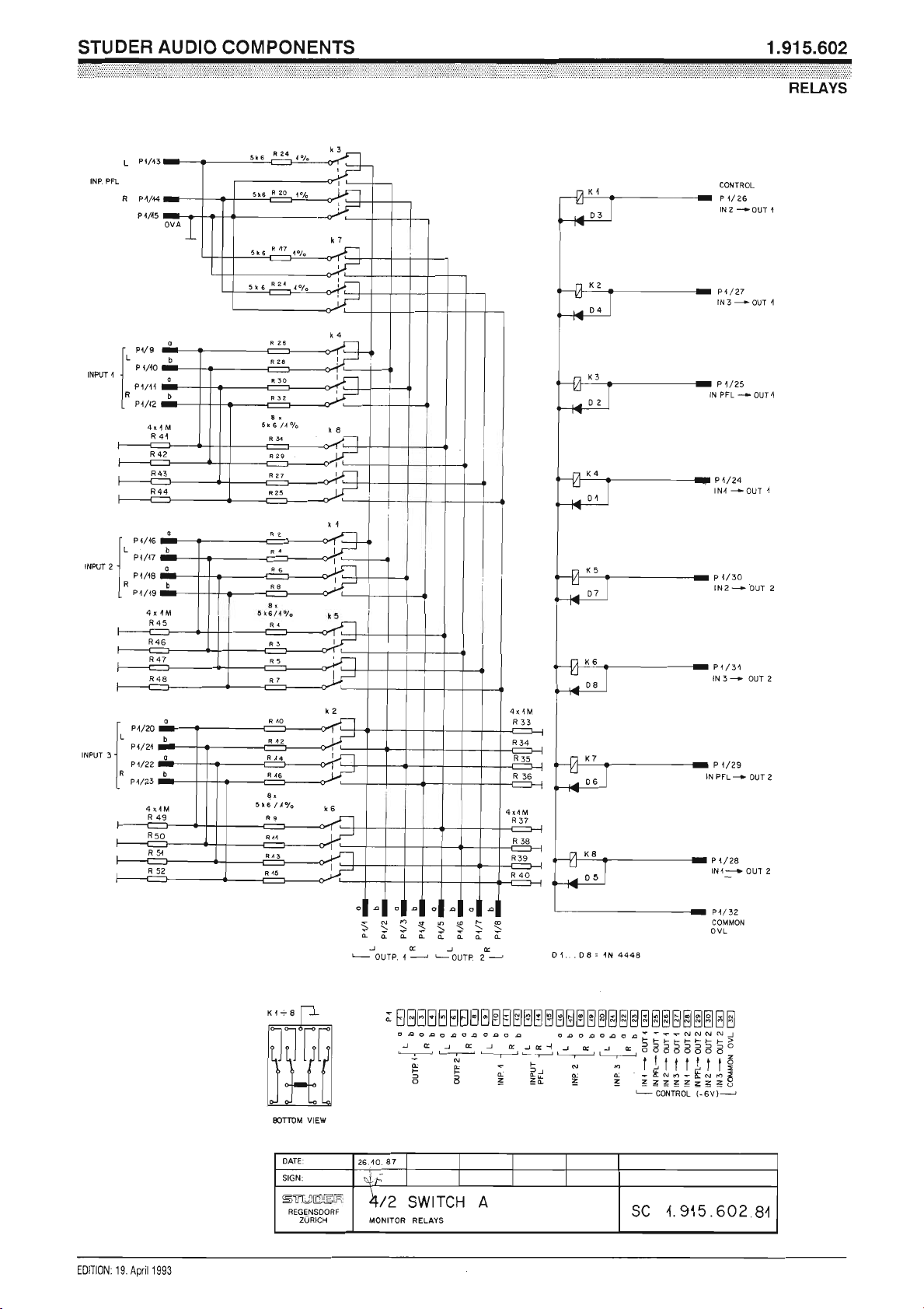
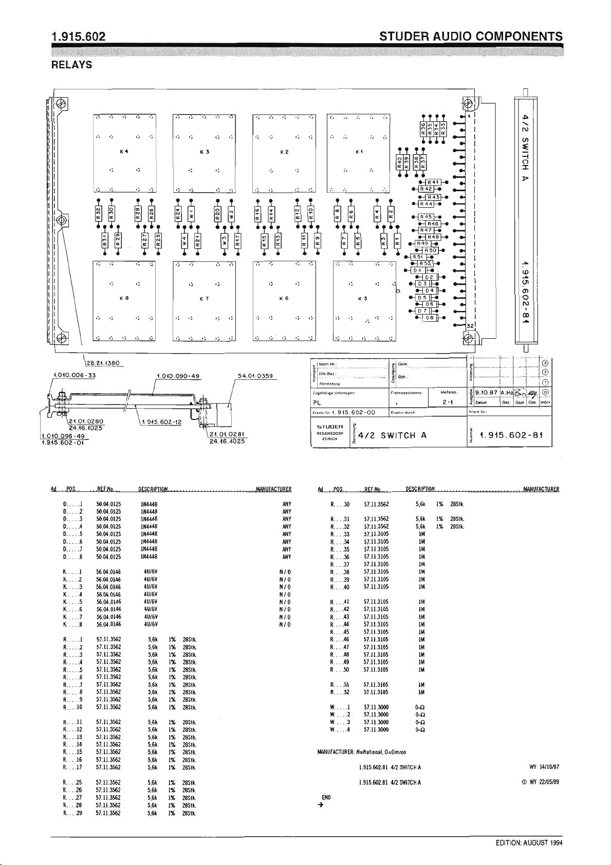
2.2.8 Monitor Switching Relays 1.915.601/602
Two different monitor circuit switching cards are available. They are
equipped with either five or eight relays for switching of a corresponding
number of stereo sources to one or two stereo outputs in monitor circuits.
The relays are available with coil ratings of 6 VDC or 24 VDC, depending
on the user’s requirement. Click-suppressing diodes are wired across each
relay coil. The relays are equipped with four double throw (change-over)
contacts each.
Isolation of the monitor lines from external circuitry is achieved by 5.6 kΩ
resistors in the “a” and “b” legs of each stereo line, thus a high impedance (bridging) load is presented to the outside source, even in deenergized (non-selected) status, when the respective pair of relay contacts
shorts the lines after the respective isolation resistors. With a relay energized, the corresponding stereo pair is routed to a stereo bus available on
four pins of the 32-contact edge connector (in case of the 5-input card
1.915.601.xx).
Date printed: 29.11.01 E45
Professional Audio System Components
Card 1.915.602.xx features a similar circuit configuration with eight relays,
to switch one unbalanced and three balanced stereo inputs. Two stereo
buses appear on eight pins of the edge-connector; in this way, the four inputs can be switched to either one or to both outputs, such as may be the
case with separate monitor circuits in the control room and in the studio.
Dimensions: Euro-card 100 × 160 mm, 4 M units wide
Weight approx. 250 g
Ordering Information: • Relay card, 5 IN/1 OUT 1.915.601.xx
• Relay card, 4 IN/2 OUT 1.915.602.xx
E46 Date printed: 29.11.01
Professional Audio System Components
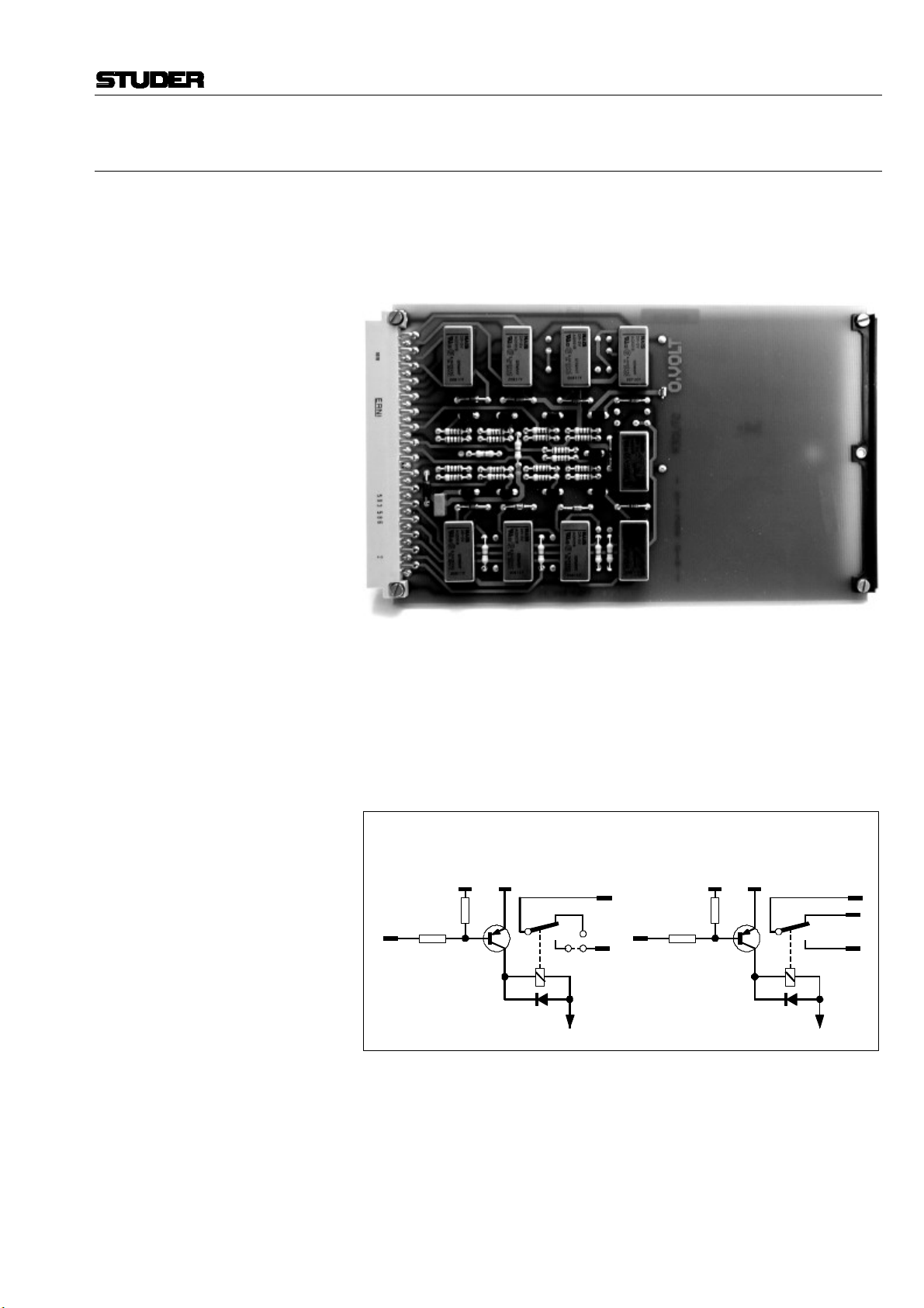
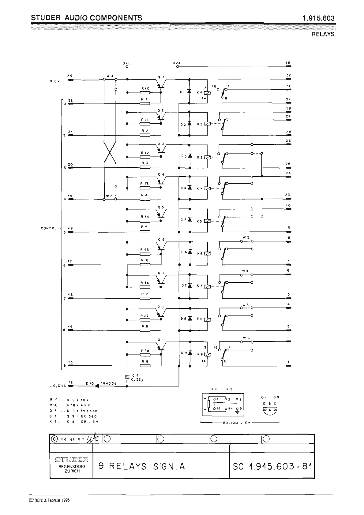
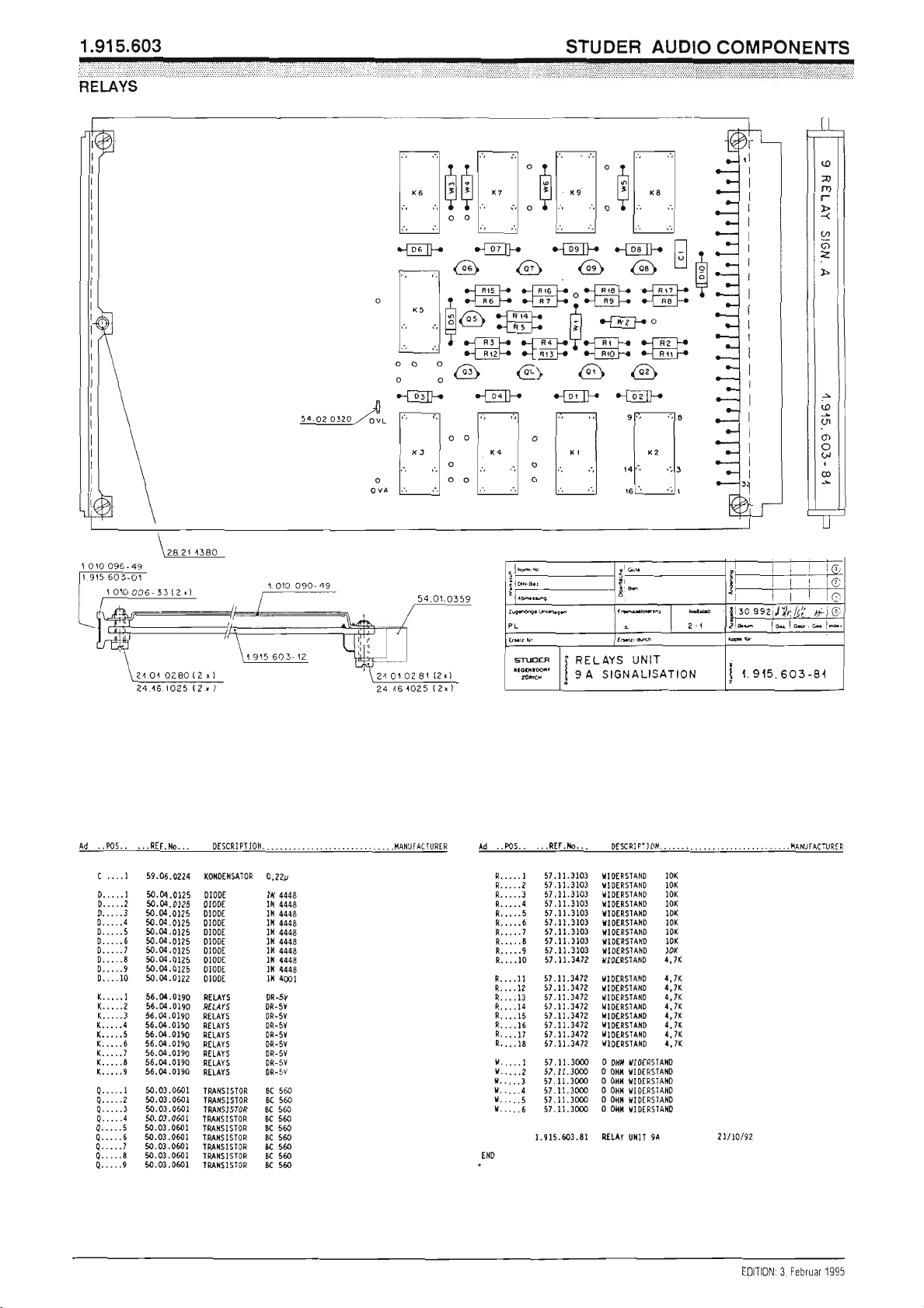
2.2.9 Transistor-Driven Relays (7+2) 1.915.603
This Euro-card is supplied with nine transistor-driven relays with singlepole, double-throw (SPDT) contacts. For two of the relays, both normally-open and normally-closed contacts are routed to the edge connector;
for the remaining seven it is jumper-selectable whether the normally-open
or the normally-closed contact is used.
The relays are designed for operation on 6 VDC, and each relay coil is
bridged with a click-suppressing diode. PNP transistors in series with the
coils are blocking the current flow, because each transistor is normally biased off. By applying the output from the gate of an external control logic
to the base of a transistor, it is switched into saturation, thereby energizing
the respective relay. This arrangement of nine relays was designed for use
in signaling systems within a studio installation; however, it may find its
use for other applications as well.
MAKE OR BREAK CONTACTS
(7 ×)
4k7
10k
– 6 V
CHANGE-OVER CONTACTS
(2 ×)
4k7
10k
– 6 V
Polarity of the relay’s supply voltage must be observed when utilizing this
circuit.
Date printed: 29.11.01 E47

Professional Audio System Components
Technical Specifications
Contact Ratings: max. 1 A/30 VDC or 0.3 A/125 V
AC
Note: In this application 48 V must not be exceeded to avoid shock hazard.
Switching power 60 VA (AC)
100 W (DC)
Dimensions: Euro-card 100 × 160 mm, 4 M units wide
Ordering Information: Transistor-driven relays 1.915.603.xx
E48 Date printed: 29.11.01
Professional Audio System Components
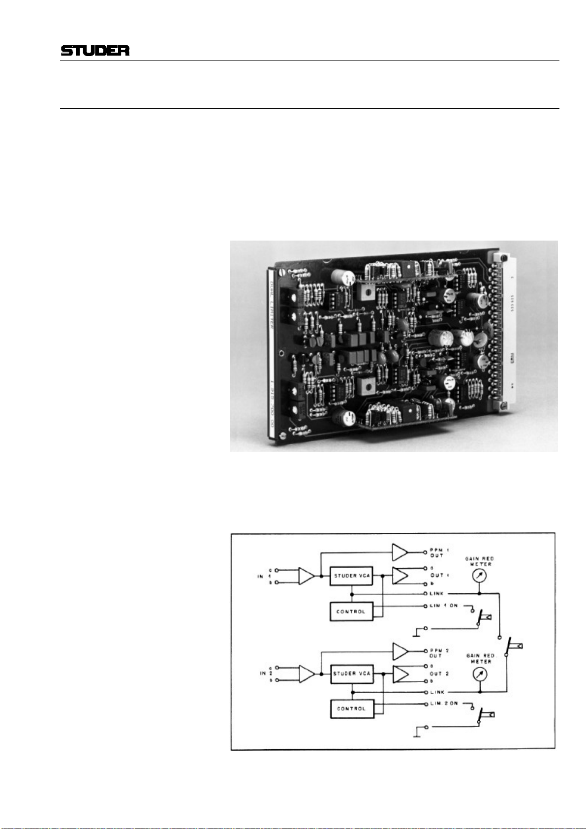
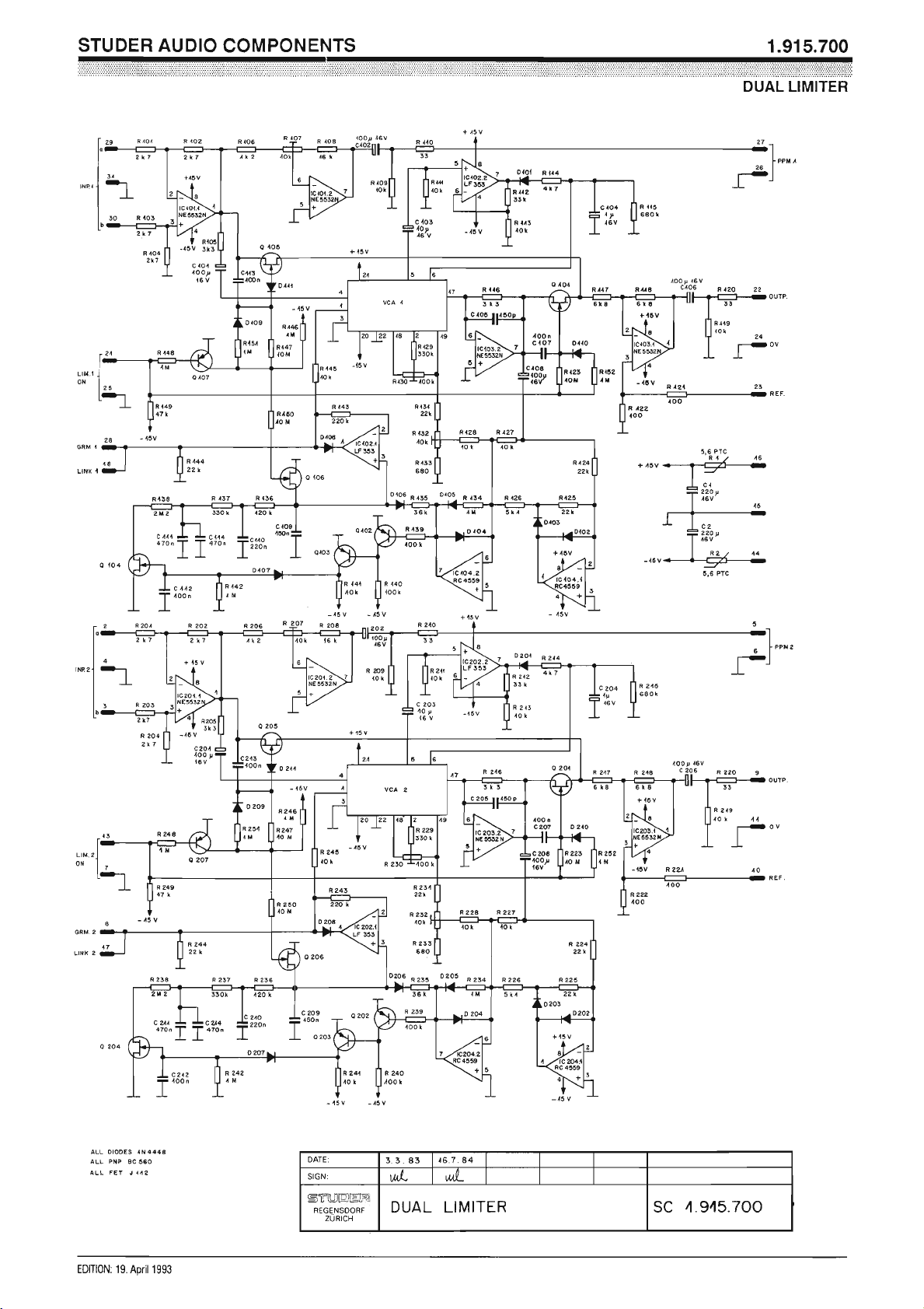
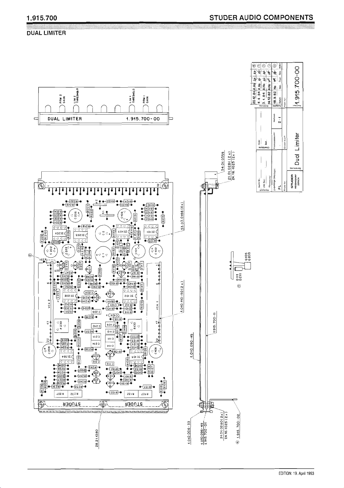
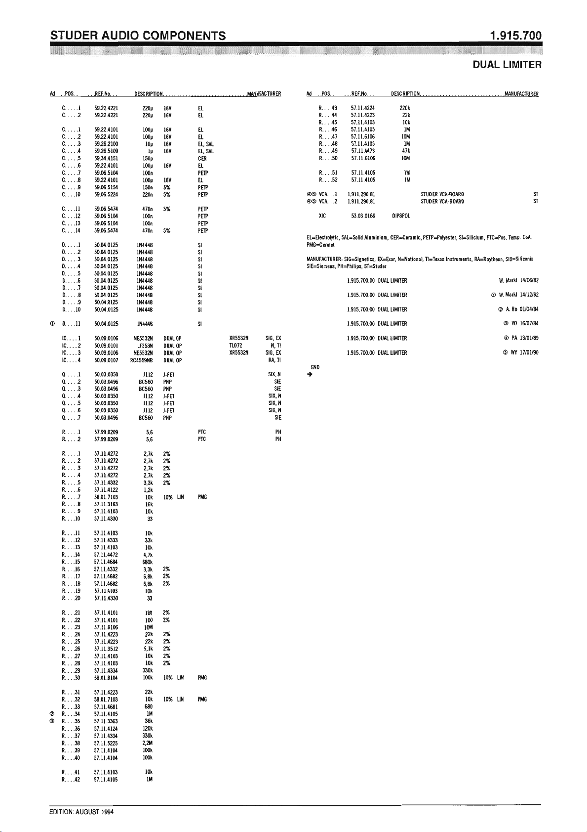
2.2.10 Dual Limiter 1.915.700
In sound work there are numerous situations where the signal amplitude
has to be limited to a pre-determined level in order to prevent overloading
of succeeding equipment, such as light modulators in film work, or radio
transmitters. With this limiter, excessive levels are automatically reduced
to a preset level, and, since regulation is controlled by the program’s energy content, the performance of this limiter is free of any “pumping” effects. Gain reduction is achieved with a Studer Voltage Controlled Amplifier (VCA) which ensures low noise performance and negligible distortion.
Two identical, independent limiter circuits are contained on one Eurocard, plus additional, separate gain stages to drive peak program meters.
The perfect tracking of the two VCAs makes this Dual Limiter suitable for
stereo work as well, in which case a simple electrical connection is needed
to link the units.
Note: Gain reduction meters (not supplied) can be connected to the LINK out-
puts as well, if required.
Date printed: 29.11.01 E49

Professional Audio System Components
Technical Specifications
Input: Impedance 5.4 kΩ, balanced configuration
2.7 kΩ, unbalanced configuration
Overload point +20 dBu (7.75 V
Output: Impedance < 50 Ω, unbalanced
Frequency response +0/–0.5 dB, 30 Hz...15 kHz
+0/–3 dB, 2 Hz...200 kHz
Gain 0 dB, limiter off
Output noise level –102 dBu, Limiter on
–106 dBu, Limiter off
Limiting ratio 20:1
Threshold –15 dBu...+3 dBu, adjustable
Limited output level –14 dBu...+4 dBu, depending on threshold setting
Attack time 1 ms
Release time 50 ms...5 s, program-dependent
PPM Section: Output impedance < 50 Ω, unbalanced
Maximum output level +20 dBu
Gain 2.5 dB...27 dB, adjustable
Frequency response +0/–3 dB, 2 Hz...200 kHz
rms
)
Supply: ±15 V (100 mA)
Dimensions: Euro-card 100 × 160 mm, 7 M units wide
Ordering Information: Dual limiter 1.915.700.xx
E50 Date printed: 29.11.01
Professional Audio System Components
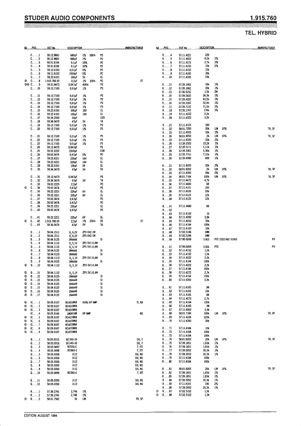
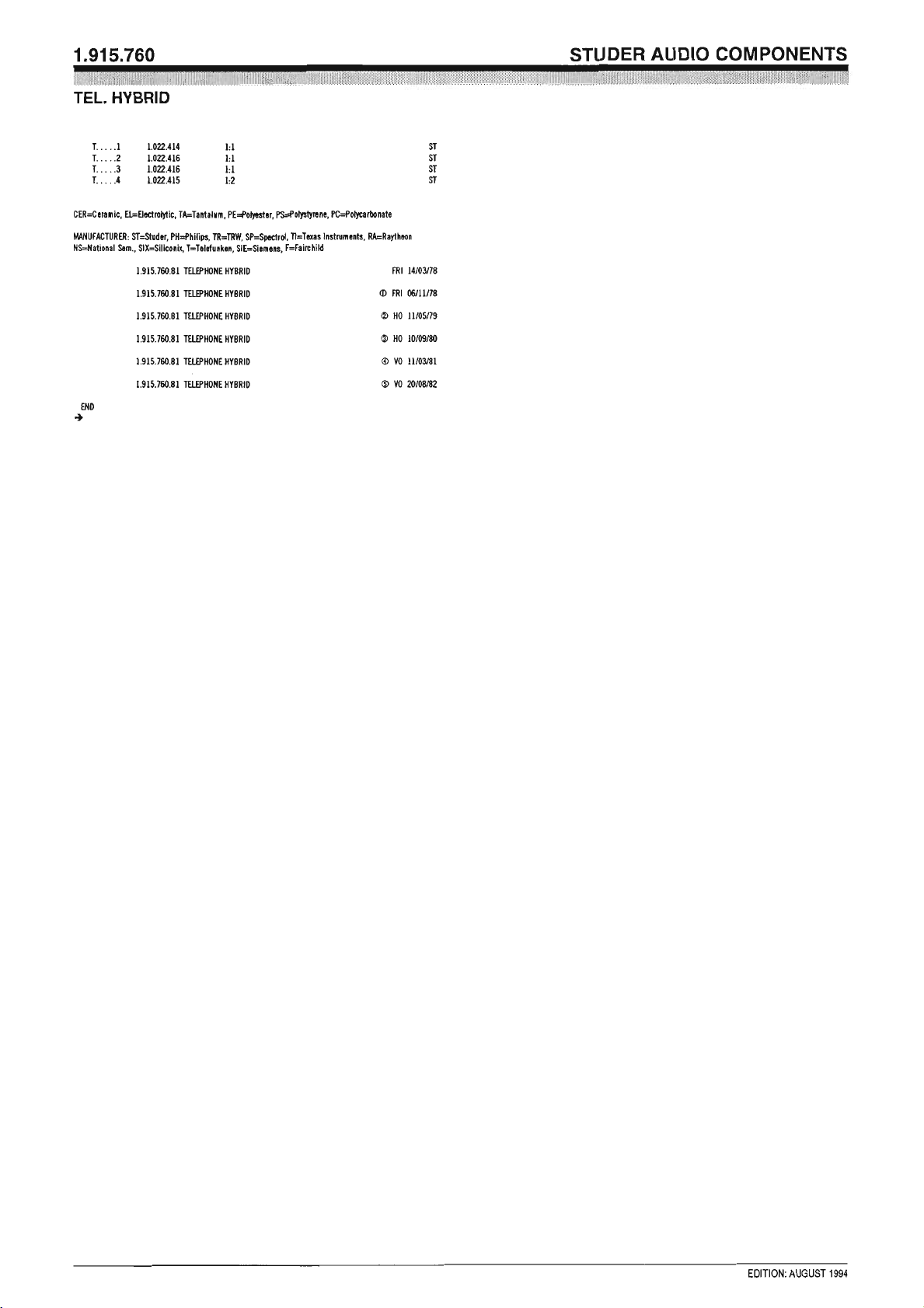
2.2.11 Telephone Hybrid 1.915.760/764
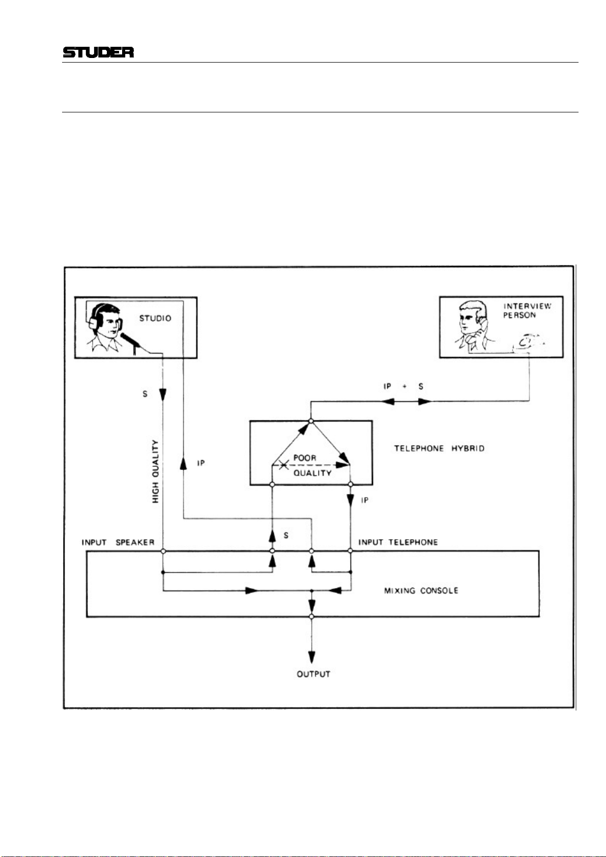
In order to record or transmit a conversation between the announcer in the
studio and a person outside the studio being interviewed by telephone, the
telephone line must be connected to the mixing console.
In such a case, the full conversation is transmitted, since both voice signals are carried on normal 2-wire telephone lines. However, also the voice
of the announcer in the studio is then transmitted in telephone quality
(300... 3400 Hz). By mixing the microphone signal of the announcer (in
studio quality) to the conversation, the addition of the “good” and “poor”
signals results in a distorted and untrue signal.
Principle of a telephone transmission via a mixing console
The telephone hybrid allows to greatly improve the quality of a telephone
transmission by selectively suppressing the undesired “poor” announcer
signal (side-tone attenuation). This side-tone attenuation is done in principle by a hybrid circuit which is a familiar feature in telephony.
Date printed: 29.11.01 E51
Professional Audio System Components
The Studer telephone hybrid permits high-quality transmission of telephone conversations with the announcer in the studio. Apart from connecting it to the telephone line, the hybrid works automatically.
Maximum side-tone attenuation of the studio voice signal in the receiver
line is achieved by automatically constituting a dummy load for the telephone line. This adjustment is performed electronically, the real (resistive)
and imaginary (capacitive) components of the telephone line impedance
being matched as near as possible. This automatical matching process begins as soon as an announcer signal is present.
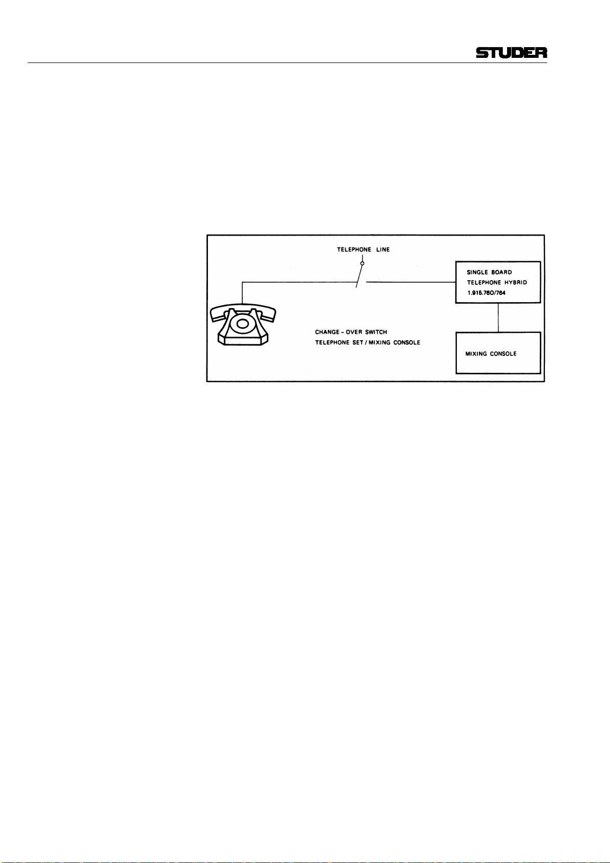
Operation with a single Telephone Hybrid Board
The telephone set is used to establish a telephone connection (call). After
switching over to the mixing console, the holding current for the subscriber’s relay is maintained by a resistor on the hybrid board.
Versions: A variety of 19” Telephone Hybrid units with one or two channels is
available, consisting of the following versions:
• Standard version (ST) – 19”/1U Telephone Hybrid unit for direct connection to the telephone line and a relay to switch the telephone line from the
telephone set to the hybrid.
• Noise gate version (NG) – same as standard version, equipped with a
noise gate
• Current-adjustable version (CA) – same as standard version, but additio nally featuring adjustable holding current for the telephone line.
Ordering Information:
Euro-cards: • Telephone hybrid card 1.915.760.xx
• Telephone hybrid card with noise gate 1.915.764.xx
19” standard products: • Telephone hybrid 1CH-ST 75.700.89118
• Telephone hybrid 2CH-ST 75.700.89228
• Telephone hybrid 1CH-NG 75.700.89114
• Telephone hybrid 2CH-NG 75.700.89224
• Telephone hybrid 1CH-CA 75.700.89116
• Telephone hybrid 2CH-CA 75.700.89226
• Telephone hybrid 1CH-CA/NG 75.700.89117
• Telephone hybrid 2CH-CA/NG 75.700.89227
E52 Date printed: 29.11.01


Professional Audio System Components
2.2.12 Line Equalizer 1.915.776/777/779
The Line Equalizer Euro-card is the ideal component to cope with situations as inadequate frequency response or excessive level loss on longhaul audio lines. Special effects equalization may be another application.
The frequency response can be varied in three bands over a ±15 dB range,
as shown by the respective graphs below. Gain is normally set to unity,
with 10 dB of continuously variable gain or attenuation available. Remote
controlled muting or bypassing is possible.
The equalizer cards are supplied with a choice of different front panels for
either horizontal recessed, vertical recessed, or vertical flush installation
into suitable mounting frames.
When installed vertically, each equalizer occupies 8 M units.
A 19” mounting frame for three equalizer cards plus the required power
supply is described below.
Date printed: 29.11.01 E53

Professional Audio System Components
Parametric filter diagrams:
HF shelving equalizer: Treble filter 700 Hz...15 kHz, ±15 dB
MF bell-shaped equalizer: Center frequency 400 Hz...7 kHz, ±15 dB; Q approx. 1
LF shelving equalizer: Bass filter 30 Hz...600 Hz, ±15 dB
E54 Date printed: 29.11.01

Professional Audio System Components
Technical Specifications
Input: balanced and floating, with RF filter
Impedance > 10 kΩ
Clipping point +24 dBu (12.3 V)
Common mode rejection > 50 dB, unbalanced to ground
Output: balanced and floating
Minimum permissible load 200 Ω
Maximum output level +24 dBu (12.3 V)
Frequency response ±0.2 dB, 30 Hz...60 kHz, equalization off
THD < 0.01%, at nominal level
Equalization: Characteristics see diagram, referred to +6 dBu in/out
S/N > 96 dB, equalizer off
> 93 dB, equalizer on (linear)
Supply: ±15 V (80 mA idling, 170 mA @ +24 dBu into 200 Ω)
Dimensions: Euro-card 100 × 160 mm, 8 M units wide
Ordering Information:
Euro-cards: • Line equalizer, horizontal, for recessed mounting 1.915.776.xx
• Line equalizer, vertical, for recessed mounting 1.915.777.xx
• Line equalizer, vertical, for flush mounting (ELMA) 1.915.779.xx
19” standard product • Mounting frame (19”/1U) with power supply and front panel,
wired for three equalizer cards 1.915.776 (not incl.) 1.918.117.xx
Date printed: 29.11.01 E55


Professional Audio System Components
2.2.13 Dual Balancing Unit/Dual Line Amplifier 1.915.904
In professional audio work it is not uncommon that equipment with unbalanced input or output configuration must be connected to a system that
is based on a strictly balanced design. The Dual Balancing Unit is the ideal
component if the requirement of matching unbalanced to balanced equipment or vice versa has to be satisfied.
The Dual Balancing Unit consists of one Euro-card which contains four
separate circuits to accommodate unbalanced-to-balanced or balanced-tounbalanced matching in a stereo system. It is the ideal choice for applications in which consumer-type stereo equipment has to be integrated into a
professional audio system, where balanced audio lines are a must. The
Dual Balancing Unit will also be used in situations where balanced auxiliary units must be connected to unbalanced insert points on a mixing desk.
E56 Date printed: 29.11.01

Professional Audio System Components
The use of the balancing unit is not restricted to matching of balanced and
unbalanced audio system components, because it can also be utilized as a
(line) booster amplifier or as a stereo-to-mono mixer. By simply connecting the unbalanced outputs and inputs together and by adjusting again
within the available ranges, two booster amplifiers with a maximum gain
of 30 dB and a maximum output capability of +24 dBu*) can be realized.
For stereo-to-mono mixing, the unbalanced sides of the amplifier sections
simply are connected by means of combining (mixing) resistors, as shown
in the diagram below.
*) To avoid signal clipping, a system should always be designed in such a
way that signal peaks stay well below an amplifier’s maximum output capacity. Alignment procedures and level settings depend to a large degree
on the type of metering used in an audio system. When making measurements with a steady-state signal, a margin of 6 dB below a system’s clipping point and the PPM deflected to “zero volume”, or a margin of 15 dB
(for programs with extreme crest factors, even 20 dB) when utilizing a
VU-meter, is considered good engineering practice.
Date printed: 29.11.01 E57

Professional Audio System Components
Technical Specifications
Balanced to unbalanced (Section 1):
Input impedance ≥ 10 kΩ, balanced/floating
Maximum input level +24 dBu
Output impedance < 100 Ω, unbalanced
Maximum output level +20 dBu
Minimum load 600 Ω
Frequency response ±0.2 dB, 30 Hz...16 kHz
Attenuation 0/15 dB; two fixed steps
0...15 dB; variable
S/N > 100 dB; attenuation set to 6 dB, line level +6 dBu
Unbalanced to balanced (Section 2):
Input impedance 5 kΩ, unbalanced
Maximum input level +20 dBu
Output impedance ≤ 50 Ω, balanced/floating
Minimum load 200 Ω
Maximum output level +24 dBu
Frequency response ±0.2 dB, 30 Hz...16 kHz
Gain 14/30 dB; two fixed steps
0...17 dB; variable
S/N > 100 dB; gain set to 6 dB, line level +6 dBu
Supply: ±15 V (70 mA, idling; 170 mA, each channel +24 dBu into 200 Ω)
Dimensions: Euro-card 100 × 160 mm, 7 M units wide
Ordering Information:
Euro-card: • Dual balancing unit 1.915.904.xx
19”/1U standard products: • 2CH balancing unit (1 × 1.915.904) 75.700.89212
• 4CH balancing unit (2 × 1.915.904) 75.700.89422
• 6CH balancing unit (3 × 1.915.904) 75.700.89632
E58 Date printed: 29.11.01


Professional Audio System Components
2.3 Racks and Frames
2.3.1 19” Mounting Frame for 3 Euro-Cards 1.918.100
This 19” mounting frame (height: 44.5 mm/1U) offers space for three
Euro-cards next to the power supply. The power supply provides ±15 V
(regulated) and 24 VDC (unregulated).
DC
The frame comes equipped with three edge connectors to accommodate
three Euro-cards horizontally, side by side. A blank back panel of anodized aluminium is provided and permits the installation of input and output connectors as required, depending on the application.
Date printed: 29.11.01 E59

Professional Audio System Components
Technical Specifications
Primary: Voltage selector for 100, 120, 140, 200, 220, 240 V
AC
Fuse (slow-blow) 400 mA (for 100...140 VAC)
200 mA (for 200...240 V
Secondary: Regulated voltage ±15 V
Unregulated voltage 24 V
, 0.5 A max.
DC
, 0.2 A max. (for signaling)
DC
AC
)
Fuses (slow-blow) 2 × 1 A
Ordering Information:
19”/1U standard product • Mounting frame for three Euro-cards with power
supply and stabilizer PCB, with two blank aluminium
back panels (1.918.100.21) 1.918.100.xx
Alternative Back Panels: The mounting frame 1.918.100.xx can be equipped with the following
back panels:
1 2 3 4 5 6 7 8 9 101112 131415
XLR
BLANK PANEL
1.918.100.21
BLANK PANEL
1.918.100.21
MAINS
XLR
1.918.113.03
MAINS
1 23
XLR
15p D
45 6
XLR
1.918.100.36 1.918.100.33
SIEMENS 30/39p
20.020.402.00
SIEMENS 30/39p
Ordering Information:
Alternative Back Panels for Mounting Frame 1.918.100
• Steel back panel for 15 × XLR sockets (Neutrik) 1.918.113.03
Alternative Back Panels for Blank Panels 1.918.100.21
• Aluminium back panel for 6 × XLR sockets (Neutrik) 1.918.100.36
• Aluminium back panel for 1 × Siemens 30/39 pin
and 1 × 15pin D-type sockets 20.020.402.00
• Aluminium back panel for 2 × Siemens 30/39 pin sockets 1.918.100.33
• Mechanical interface Siemens panel
2.3.4.
1.918.100.01
SIEMENS 30/39p
→
D-type connector: see chapter
E60 Date printed: 09.01.02


Professional Audio System Components
2.3.2 19” Ventilation Unit/19” Blank Panels 1.918.119/0XX
When filling a cabinet rack with various electronic equipment, considerable heat may be generated, which could be harmful to other nearby components. To provide for sufficient convection cooling, the use of ventilation units above and below the heat-generating equipment is strongly recommended.
Ordering Information:
19” Ventilation Units
19” Blank Panels
A ventilation unit consists of a 19” wide and 1U high sheet metal structure, which extends about 340 mm into the rack. The unit’s front section is
perforated, with a slanting metal panel mounted inside. By installing the
ventilation unit with that panel either slanting upwards or downwards, the
air flow can be directed as desired.
If only moderate heat problems have to be coped with, it may be sufficient
to use one ventilation unit above or below the heat source, and to provide
sufficient spacing from adjacent equipment by installing a 1U blank panel
on the opposite side.
• Ventilation unit 19”/1U 1.918.119.xx
• Ventilation unit without air guide panel 1.918.119.09
• Blank panel 19”/1U high, anodized finish 1.918.001.xx
• Blank panel 19”/2U high, anodized finish 1.918.002.xx
• Blank panel 19”/3U high, anodized finish 1.918.003.xx
• Blank panel 19”/1U high, plastic coated, grey 1.918.001.09
• Blank panel 19”/2U high, plastic coated, grey 1.918.002.09
• Blank panel 19”/3U high, plastic coated, grey 1.918.003.09
• Blank panel 19”/1U high, paint finish, grey 1.918.011.xx
• Blank panel 19”/2U high, paint finish, grey 1.918.012.xx
• Blank panel 19”/3U high, paint finish, grey 1.918.013.xx
Date printed: 29.11.01 E61

Professional Audio System Components
2.3.3 19” Euro-Card Mounting Frames 1.918.318/319
The Euro-card mounting frame (sometimes also referred to as 19” Sub
Rack) is an empty structure which fits into any standard 19” rack. It is intended to accommodate PCBs of the Euro format vertically, side by side.
The available space within the sub rack is divided into 84 Modular
Widths, each measuring 5.08 mm (0.2 inches). One Euro-card usually occupies 7 M (Module) widths, thus up to 12 Euro-cards may be installed.
The Euro-card frame is supplied as a kit for assembly by the user. Assembly instructions are included with each kit.
Supplied with the kit is a hinged front panel of anodized aluminium, providing quick access to the plug-in PCBs if required. This front panel and
its hinges are available separately in case a damaged panel or hinge needs
to be replaced.
Separate edge connectors and slide rails are required for each Euro-card
and power supply unit installed into the Euro-card frame. Mounting kits
containing the slide rails, edge connectors, and other accessories are described below (1.918.315/316).
To provide for convection cooling within an equipment rack, the Ventilation Unit 1.918.119.xx is recommended.
Euro-Card Racks, Ordering Information:
• Euro-card frame (19”/3U, ELMA), direct access to
32pin connectors on back panel 1.918.318.xx
• Euro-card frame (19”/3U, ELMA) with additional rear
panel, for max. 10 freely assignable connector panels 1.918.319.xx
E62 Date printed: 29.11.01

Professional Audio System Components
2.3.4 19” Euro-Card Mounting Accessories
Euro-Card Mounting Kit For installing Euro-cards and/or a power supply unit into a Euro-card
frame 1.918.318/319, suitable edge connectors and guide rails are required.
Euro-Card Mounting Kit, Ordering Information:
• Mounting kit for 1 Euro-card (ELMA rack); see photograph 1.918.315.xx
• Mounting kit for power supply 1.915.100 1.918.316.xx
Connector Panels: The connector panels fit into the Euro-card frame with back panel
(1.918.319). Please order the suitable panels separately.
Date printed: 29.11.01 E63

Professional Audio System Components
Connector Panel (3U high) Ordering Information:
• Blank panel 1.918.319.21
• Panel for Siemens connector (cut out 18 × 67 mm) * 1.918.319.22
• Panel for mains inlet and 2 banana sockets 1.918.319.23
• Panel for 4 XLR sockets 1.918.319.24
* Siemens Connector Sets: Including male and female connector:
– Siemens 30pin, without connector panel 1.900.080.xx
– Siemens 39pin, without connector panel 1.900.081.xx
* D-Type Adapter Panels: The Siemens connector panel can be used as a base for mounting a D-type
connector adapter panel. The adapter sets listed below include male and
female connectors, connector cover, bolting spring, clamp, and adapter
panel:
Adapter Panel Ordering Information:
The adapter kits consist of male and female D-type connector, metal or
plastic connector cover, adapter panel, and mounting hardware, to fit on
the Siemens connector panels 1.918.319.22 (for 3U frames) or
1.918.100.33 (for 1U frames):
– D-type set, 9pin, metal connector cover 1.900.075.xx
– D-type set, 15pin, metal connector cover 1.900.076.xx
– D-type set, 25pin, metal connector cover 1.900.077.xx
– D-type set, 37pin, metal connector cover 1.900.078.xx
– D-type set, 50pin, metal connector cover 1.900.079.xx
– D-type set, 9pin, plastic connector cover 1.970.075.xx
– D-type set, 15pin, plastic connector cover 1.970.076.xx
– D-type set, 25pin, plastic connector cover 1.970.077.xx
– D-type set, 37pin, plastic connector cover 1.970.078.xx
– D-type set, 50pin, plastic connector cover 1.970.079.xx
E64 Date printed: 09.01.02

Professional Audio System Components
Extension Board: For alignment and repair, a Euro-card may have to be operated outside the
mounting frame. To facilitate any service work that has to be performed
on individual cards, extending the card’s 32 electrical connections is possible by means of a flexible extension board.
Ordering Information: Extension PCB for Euro-cards, 2 × 32pin, flexible 1.228.327.82
Date printed: 29.11.01 E65


 Loading...