How it Works
Log In / Sign Up
Buy Points
How it Works
FAQ
Contact Us
Questions and Suggestions
Users
Studer
Loading...
M
MBC 24-32/1
Micro Series
N
Neotape
O
OnAir1000
2
OnAir 1500
3
ON-AIR-2000
2
OnAir2000M2
3
OnAir 2500
2
OnAir 3000
3
OnAir 500
OnAir5000
OnAir 500 Modulo
P
PI-1975-03A
2
PI-1977-16
PR99MKII
4
PR99 MKIII
R
RCC-01
RCC-02
4
RCC-03
4
RCM-01
REVOX A77
2
Revox B226
Revox B250-S
REVOX B77
RPS-01
S
SBM-01
SBM-02
SI 1212
SI 1224
SI 1248
SI 1624
SI 2324
SI 2348
SI 3324
SI 3548
SI 612
SI 624
SI 648
SI 812
SI 824
SI SERIES
Solsafe concept
T
TBA931
2
TCA561
TOA-80
V
VarioString
VarioString VS-120
2
VarioString VS-70
VEight
Vista
3
Vista 1
3
Vista 5 M2
2
Vista 5 M3
Vista 8
Vista 9
VS-120
VS-70
X
Xcom-232i
Xcom-GSM
2
Xcom-LAN
Xcom-MS
XPC 1400-12
2
XPC 2200-24
2
XPC 2200-48
2
XP-COMPACT XPC 1112
XP-COMPACT-XPC 1400-12
2
XP-COMPACT XPC 1624
XP-COMPACT XPC 1648
XP-COMPACT-XPC 2200-24
2
XP-COMPACT-XPC 2200-48
2
Xtender XTH 3000-12
Xtender XTH 5000-24
Xtender XTH 6000-48
Xtender XTH 8000-48
XTH 3000-12
2
XTH 5000-24
2
XTH 6000-48
2
XTH 8000-48
2
XTM 1500-12
2
XTM 2000-12
2
XTM 2400-24
2
XTM 2600-48
2
XTM 3500-24
2
XTM 4000-12
XTM 4000-48
2
XTS 1200-24
XTS 1400-48
XTS 900-12
Loading...
Loading...
Nothing found
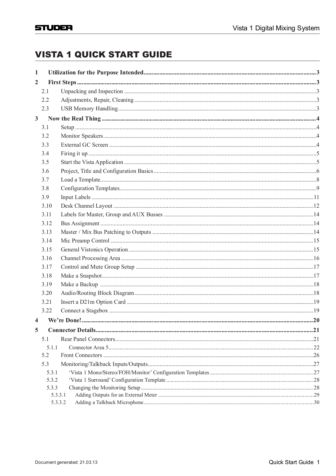
Vista 1
Operating Instructions Manual
401 pgs
36.31 Mb
0
Quick Start Manual
44 pgs
10.94 Mb
0
User Manual
46 pgs
7.89 Mb
1
Table of contents
Loading...
Studer Vista 1 User Manual
...
Studer User Manual
Download
Specifications and Main Features
Frequently Asked Questions
User Manual
Download
Loading...
+
hidden pages
Unhide
You need points to download manuals.
1 point = 1 manual.
You can buy points or you can get point for every manual you upload.
Buy points
Upload your manuals
 Loading...