


Disclaimer
Please note that this is not an official Studer document. The circuit diagram (page 3) and the PCB artwork (pages 4/5) have been re-drawn from an existing PCB, and this document has been compiled by myself in my leisure time. I tried hard to avoid any errors; however I’m human, and humans make mistakes. Therefore I have to disclaim any responsibility for correctness or consequential damage resulting from use of the information contained herewithin. Of course, Studer Professional Audio GmbH disclaims any responsibility and liability as well.
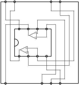
TBA931 Replacement PCB 1.081.998.00 (picture page 2)
-Direct replacement for the discontinued TBA931 chip in audio circuits only.
-The PCB according to pages 3...5 is single-sided, page 4 shows the copper side.
-The pins 1.010.015.54 were manufactured by Studer according to the drawing on page 6; they are no more available. Please note that two of these pins (the ones touching the front faces of the NE5532) must be insulated by a short piece of PTFE tubing or any other insulating material; the photograph (page 2) only shows one of them. Photograph provided by Martin Berner.
-Components for the compensation of the TBA 931 are no more used since the NE5532 is internally compensated. They may remain on the PCB, the TBA931's compensation pins are not used by the replacement PCB.
-Pins might be replaced by pieces of multi-pin headers according to page 7. However, make sure that the pins of the header match the dimensions of the pin according to the drawing on page 6. Perhaps you will prefer to remove the pins from the plastic holder before using them. You may want to use a precision IC socket for easy alignment of the pins before soldering.
-Why not use blank wire (approx. 0.6 mm dia.) instead of the pins and the TBA931's socket? When doing so, please allow for an air gap between the top of the NE5532 and the PCB which the replacement PCB is mounted on, in order to ease the NE5532's heat dissipation.
-Pad holes on the original PCB are all 0.8 mm dia. When fabricating your own PCB, make sure that the holes for the header pins match the ones you have available. You may want to drill the holes for the NE5532 somewhat larger, then you can shift it in place before soldering.
TBA931 Replacement PCB 1.080.770.81 (info on pages 8 and up)
-This PCB may be used only for the VU meter amp 1.080.807.
-The PCB is single-sided, its layout is shown on page 9 (component side).
-Instead of using this PCB, it is recommended to replace a TBA931 from the audio electronics by the replacement 1.081.998.00. Then you can use this TBA931 for the VU meter amp.
-The same pins as mentioned above are used for this PCB, so the hints given above apply here as well. The only difference is that 14 pins are used here.
Please do not hesitate to inform me on any problems (or success), I will be glad to receive any feedback either through the Studer list or to my private email address.
Robert Schrott (schrott@pop.agri.ch)
TBA931 information (added 080626)
TBA931-1 - Studer order no. 50.05.0139
TBA931-2 - Studer order no. 50.05.0140
TBA931-3 - Studer order no. 50.05.0141
Please note: Some fragments of the original TBA931 data sheet (by ITT/Intermetall, later from Philips) have been added to the folder that contains this document.
Important:
During the search for information I learned that all the items used by Studer have been selected for the ±18 V supply voltage. Do not expect a TBA 931 purchased somewhere else to work with supply voltages larger than ±13 V!

14 |
13 |
9 |
8 |
V+ |
|
|
|
|
|
NE5532 |
|
|
|
|
|
|
V– |
|
1 |
2 |
3 |
4 |
|
1 |
|
5 |
6 |
7 |
 Loading...