


XTS 1400-48
Studer XTS 1400-48, XTS 900-12, XTM 4000-48, XTH 5000-24, XTM 3500-24 User Manual
...
Studer Innotec SA 2013 – V4.5.0
4O9A
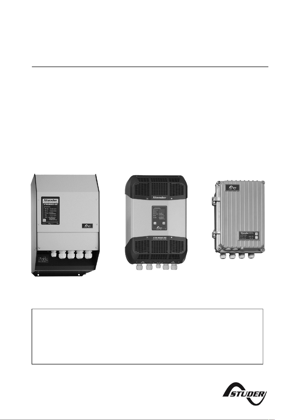
Xtender, Unit combining inverter,
battery charger and transfer system
User manual
XTS 900-12
XTS 1200-24
XTS 1400-48
XTM 1500-12
XTM 2000-12
XTM 2400-24
XTM 3500-24
XTM 2600-48
XTM 4000-48
XT
H 3000-12
XTH 5000-24
XTH 6000-48
XTH 8000-48
Common Accessories
Temperature sensor: ............................................ BTS-01
Accessories XTM/XTS:
Remote command module: .............................. RCM-10
Accessories XTS:
External cooling fan: ............................................ ECF-01
External auxiliary relay module: .......................... ARM-02

Studer Innotec SA
Xtender

Studer Innotec SA
Xtender
User manual V4.5.0 3
SUMMARY
1 INTRODUCTION.......................................................................................................................................5
2 GENERAL INFORMATION .......................................................................................................................5
2.1 Operating instructions ......................................................................................................................... 5
2.2 Conventions .......................................................................................................................................... 6
2.3 Quality and warranty ........................................................................................................................... 6
2.3.1 Exclusion of warranty ....................................................................................................................... 7
2.3.2 Exclusion of liability ........................................................................................................................... 7
2.4 Warnings and notes ............................................................................................................................. 7
2.4.1 General .............................................................................................................................................. 7
2.4.2 Precautions for using the batteries ............................................................................................... 8
3 ASSEMBLY AND INSTALLATION .............................................................................................................9
3.1 Handling and moving .......................................................................................................................... 9
3.2 Storage ................................................................................................................................................... 9
3.3 Unpacking .............................................................................................................................................. 9
3.4 Installation site ....................................................................................................................................... 9
3.4.1 XTM and XTH ..................................................................................................................................... 9
3.5 Fastening ................................................................................................................................................ 9
3.5.1 Fastening of the XTH model .........................................................................................................10
3.5.2 Fastening of the XTM model ........................................................................................................10
3.5.3 Fastening of the XTS model ..........................................................................................................10
3.6 Connections ........................................................................................................................................11
3.6.1 General recommendations .........................................................................................................11
3.6.2 Device connection compartment XTH - XTM ...........................................................................12
3.6.3 Device connection compartment XTS ......................................................................................13
3.6.4 Elements of connection cabinet ................................................................................................14
4 CABLING ...............................................................................................................................................16
4.1 Choice of system ................................................................................................................................16
4.1.1 Hybrid type stand-alone systems ................................................................................................16
4.1.2 Grid-connected emergency systems ........................................................................................16
4.1.3 Integrated mobile systems ...........................................................................................................16
4.1.4 Multi-unit systems ............................................................................................................................16
4.1.5 Distributed Minigrid ........................................................................................................................17
4.2 Earthing system ...................................................................................................................................17
4.2.1 Mobile installation or installation connected to the grid via plug connector ...................17
4.2.2 Stationary installation ....................................................................................................................18
4.2.3 Installation with automatic PE-neutral switching .....................................................................18
4.2.4 Lightning protection ......................................................................................................................18
4.3 Recommendations for dimensioning the system .........................................................................18
4.3.1 Dimensioning the battery .............................................................................................................18
4.3.2 Dimensioning the inverter .............................................................................................................19
4.3.3 Dimensioning the generator ........................................................................................................19
4.3.4 Dimensioning the renewable energy sources..........................................................................19
4.4 Wiring diagrams ..................................................................................................................................19
4.5 Connecting the battery ....................................................................................................................19
4.5.1 Battery cable cross-section and DC protective devices .......................................................20
4.5.2 Connecting the battery (Xtender side) .....................................................................................20
4.5.3 Fuse mounting on battery positive pole (XTM only) ................................................................21
4.5.4 Battery-side connection ...............................................................................................................21
4.5.5 Earthing the battery ......................................................................................................................22
4.5.6 Connecting the consumers at the AC output .........................................................................22
4.5.7 Connecting the AC supply sources ...........................................................................................23
4.5.8 Wiring auxiliary contacts ...............................................................................................................23
4.5.9 Connecting the communications cables .................................................................................23
5 XTENDER PARAMETER SETTING ............................................................................................................24
5.1 Basic parameter setting in the XTS ..................................................................................................24
6 POWERING UP THE INSTALLATION .......................................................................................................25
6.1 Connecting the battery ....................................................................................................................25

Studer Innotec SA
Xtender
User manual V4.5.0 4
6.2 Putting the Xtender(s) in operation using the main ON/OFF switch (1) if present .................25
6.3 Connecting the consumers at the output ....................................................................................25
6.4 Activating the input circuit breaker(s) (H) .....................................................................................25
7 DESCRIPTION OF THE MAIN FUNCTIONS ............................................................................................26
7.1 Inverter ..................................................................................................................................................26
7.1.1 Automatic load detection (load search) .................................................................................26
7.2 Transfer relay ........................................................................................................................................26
7.2.1 Type of detection of AC input loss (UPS) ...................................................................................27
7.2.2 Limiting the AC input current ”Input limit” .................................................................................27
7.3 Battery charger ...................................................................................................................................28
7.3.1 Working principle ...........................................................................................................................28
7.3.2 Battery charger current setting ...................................................................................................30
7.3.3 Battery protection ..........................................................................................................................30
7.4 Xtender protection ............................................................................................................................30
7.4.1 Protection in case of overload ....................................................................................................30
7.4.2 Protection against overvoltage ..................................................................................................30
7.4.3 Protection against overheating ..................................................................................................30
7.4.4 Protection against battery reverse polarity ..............................................................................31
7.5 Auxiliary contacts ...............................................................................................................................31
7.6 The real time clock .............................................................................................................................31
7.7 Entry command (Remote control on/off) .....................................................................................32
8 MULTI-UNIT CONFIGURATION .............................................................................................................33
8.1 Three-phase system............................................................................................................................33
8.2 Increasing the power by paralleling units......................................................................................33
8.3 Combined system ..............................................................................................................................34
8.4 Enlargement of an existing installation ...........................................................................................34
9 ACCESSORIES .......................................................................................................................................35
9.1 Remote control RCC-02/-03 .............................................................................................................35
9.2 BTS-01 temperature sensor ...............................................................................................................36
9.2.1 Connecting the temperature sensor (BTS-01) ..........................................................................36
9.3 Remote control Module RCM-10 (XTM/XTS) ..................................................................................36
9.3.1 Connection of the RCM-10 module ...........................................................................................36
9.4 Time and communication module TCM-01(XTS) ..........................................................................37
9.5 Auxiliary Relay Module ARM-02 (XTS) .............................................................................................37
9.6 External Cooling Fan unit ECF-01 (XTS) ...........................................................................................37
10 OTHER XTENDER SYSTEM COMPATIBLE DEVICES ...............................................................................38
10.1 Battery status processor BSP – 500/1200 .........................................................................................38
10.2 Communication module Xcom-232i ..............................................................................................38
10.3 Mppt solar charge controller VarioTrack .......................................................................................38
11 CONTROL ..............................................................................................................................................39
11.1 Main on/off control ............................................................................................................................39
11.2 Display and control panel ................................................................................................................39
12 MAINTENANCE OF THE INSTALLATION ...............................................................................................41
13 PRODUCT RECYCLING .........................................................................................................................41
14 EC DECLARATION OF CONFORMITY ..................................................................................................41
15 COMMENTS OF APPENDIX DRAWINGS ..............................................................................................42
16 DRAWING’S ELEMENTS (DC SIDE) ........................................................................................................44
17 FIGURE ELEMENT'S (AC PART) ..............................................................................................................45
18 MECHANICAL DIMENSION AND MOUNTING ELEMENT .....................................................................46
19 NAMEPLATE (FIG. 1B) ...........................................................................................................................46
20 TABLE OF FACTORY DEFAULT PARAMETER SETTINGS .........................................................................47
21 TECHNICAL DATA .................................................................................................................................53
22 NOTES ....................................................................................................................................................54

Studer Innotec SA
Xtender
User manual V4.5.0 5
1 INTRODUCTION
Congratulations! You are about to install and use a device from the Xtender range. You have chosen
a high-tech device that will play a central role in energy saving for your electrical installation. The
Xtender has been designed to work as an inverter / charger with advanced functions, which can be
used in a completely modular way and guarantee the faultless functioning of your energy system.
When the Xtender is connected to a generator or network, the latter directly supplies the consumers,
and the Xtender works like a battery charger and backup device if necessary. The powerful battery
charger has an exceptional high efficiency and power factor correction (PFC) close to 1. It
guarantees excellent battery charging in all situations. The charge profile is freely configurable
according to the type of battery used or the method of usage. The charge voltage is corrected
depending on the temperature, thanks to the optional external sensor. The power of the charger is
modulated in real time dependent according to the demand of the equipment connected at the
Xtender output and the power of the energy source (network or generator). It can even temporarily
backup the source if the consumer demand exceeds the source capacity.
The Xtender continuously monitors the source to which it is connected (network or generator) and
disconnects itself immediately if the source is missing, disturbed or does not correspond to the quality
criteria (voltage, frequency, etc.). It will then function in independent mode, thanks to the integrated
inverter. This inverter, which has an extremely robust design, benefits from STUDER Innotec’s many
years of experience and expertise in this area. It could supply any type of load without faults, enjoying
reserves of additional power that is unmatched in the market. All your equipment will be perfectly
provided with energy and protected from power outages in systems where energy supply is
unpredictable (unreliable network) or voluntarily limited or interrupted, such as hybrid installations on
remote sites or mobile installations.
The parallel and/or three-phase network operation of the Xtender offers modularity and flexibility and
enables optimum adaptation of your system to your energy requirements.
The RCC-02/-03 control, display and programming centre (optional) enables optimum configuration
of the system and guarantees the operator continuous control for all important parameters in the
installation.
In order to guarantee flawless commissioning and functioning of your installation, please read this
manual carefully. It contains all the necessary information relating to the functioning of the inverters
/ chargers in the Xtender series. The setting up of such a system requires special expertise and may
only be carried out by qualified personnel familiar with the applicable local regulations.
2 GENERAL INFORMATION
2.1 OPERATING INSTRUCTIONS
This manual is an integral part of each inverter/charger from the Xtender series.
It covers the following models and accessories1:
Inverter/charger:
XTH 3000-12 – XTH 5000-24 – XTH 6000-48 – XTH 8000-48
XTM 1500-12, XTM 2000-12, XTM 2400-24,
XTM 3500-24, XTM 2600-48, XTM 4000-48
XTS 900-12, XTS 1200-24, XTS 1400-48
External cooling fan: ECF-01
Temperature sensor: BTS-01
Remote command module: RCM-10
Auxiliary relay module: ARM-02
For greater clarity, the device is referred to in this manual as Xtender, unit or device, when the
description of its functioning applies indiscriminately to different Xtender models.
These operating instructions serve as a guideline for the safe and efficient usage of the Xtender.
Anyone who installs or uses an Xtender can rely completely on these operating instructions, and is
bound to observe all the safety instructions and indications contained. The installation and
commissioning of the Xtender must be entrusted to a qualified professional. The installation and
usage must conform to the local safety instructions and applicable standards in the country
concerned.
1
Also for 120Vac model (-01)
Studer Innotec SA
Xtender
User manual V4.5.0 6
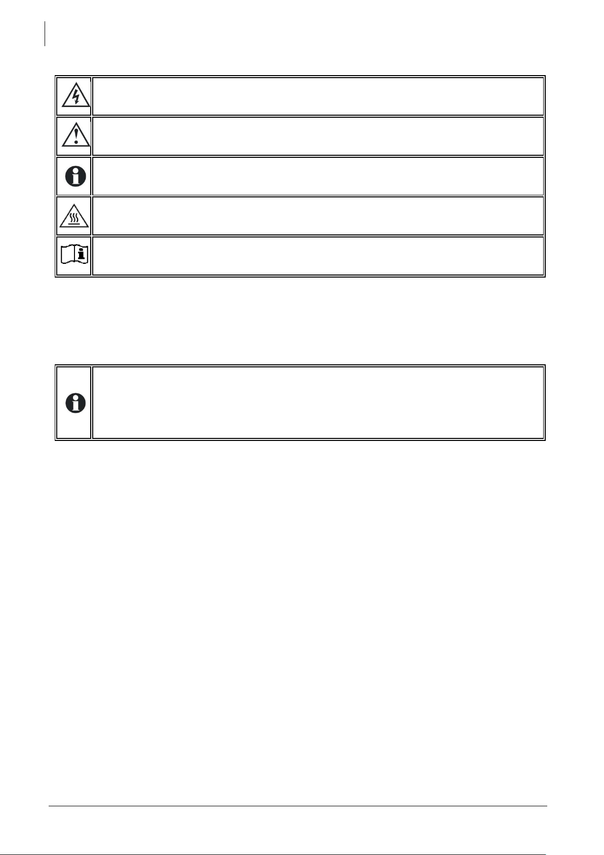
2.2 CONVENTIONS
This symbol is used to indicate the presence of a dangerous voltage that is sufficient to
constitute a risk of electric shock.
This symbol is used to indicate a risk of material damage.
This symbol is used to indicate information that is important or which serves to optimise your
system.
This symbol placed on the product indicates that its surfaces may reach temperatures
higher than 60°C.
This symbol placed on the product indicates that its use must follow the instructions in the
user’s manual.
All values mentioned hereafter, followed by a parameter number indicate that this value may be
modified using the RCC-02/-03 remote control.
In general, the default values are not mentioned and are replaced by a parameter number in the
following format: {xxxx}. The default values for this parameter are specified in the defaults parameter
table, p. 47.
All parameter values modified by the operator or installer must be transferred into the same
table. If a parameter not appearing in the list (advanced parameters) has been modified
by an authorised person with technical knowledge, they will indicate the number of the
modified parameter(s), the specifications of the parameter(s) and the new value set, at the
end of the same table.
All figures and letters indicated in brackets or in square brackets refer to items that can be found in
the separate manual “Appendix to the installation and operating instructions” supplied with the
device. In this appendix, these figures and letters are encircled.
The figures in brackets refer to elements belonging to the Xtender.
The uppercase letters in brackets refer to AC cabling elements.
The lowercase letters in brackets refer to battery cabling elements.
The comments on figures and items of the appendix are given starting on p. 42.
2.3 QUALITY AND WARRANTY
During the production and assembly of the Xtender, each unit undergoes several checks and tests.
These are carried out with strict adherence to the established procedures. Each Xtender has a serial
number allowing complete follow-up on the checks, according to the particular data for each
device. For this reason it is very important never to remove the type plate (appendix 1 – fig. 3b) which
shows the serial number. The manufacture, assembly and tests for each Xtender are carried out in
their entirety by our factory in Sion (CH). The warranty for this equipment depends upon the strict
application of the instructions appearing in this manual.
Studer Innotec SA
Xtender
User manual V4.5.0 7
2.3.1 Exclusion of warranty
No warranty claims will be accepted for damage resulting from handling, usage or processing that
does not explicitly appear in this manual. Cases of damage arising from the following causes are
notably excluded from the warranty:
Surge voltage on the battery input (for example, 48 V on the battery input of an XTH 3000-12)
Incorrect polarity of the battery
The accidental ingress of liquids into the device or oxidation resulting from condensation
Damage resulting from falls or mechanical shocks
Modifications carried out without the explicit authorisation of Studer Innotec
Nuts or screws that have not been tightened sufficiently during the installation or
maintenance
Damage due to atmospheric surge voltage (lightning)
Damage due to inappropriate transportation or packaging
Disappearance of original marking elements
2.3.2 Exclusion of liability
The placement, commissioning, use, maintenance and servicing of the Xtender cannot be the
subject of monitoring by Studer Innotec. Therefore, we assume no responsibility and liability for
damage, costs or losses resulting from an installation that does not conform to the instructions,
defective functioning or deficient maintenance. The use of a Studer Innotec inverter is the
responsibility of the customer in all cases.
Studer Innotec shall in no event be liable for consequential, incidental, contingent or special
damages, even if having been advised of the probability of such damages. This equipment is neither
designed nor guaranteed to supply installations used for vital medical care nor any other critical
installation carrying significant potential damage risks to people or the environment.
Studer Innotec assumes no responsibility for the infringement of patent rights or other rights of third
parties that result from using the inverter.
Studer Innotec reserves the right to make any modifications to the product without prior notification.
2.4 WARNINGS AND NOTES
2.4.1 General
This manual is an integral part of the device and must be kept available for the operator
and installer. It must remain close to the installation so that it may be consulted at any time.
The parameter table available at the end of the manual (p. 47) must be kept up to date in the event
of modification of the parameters by the operator or installer. The person in charge of installation
and commissioning must be wholly familiar with the precautionary measures and the local
applicable regulations.
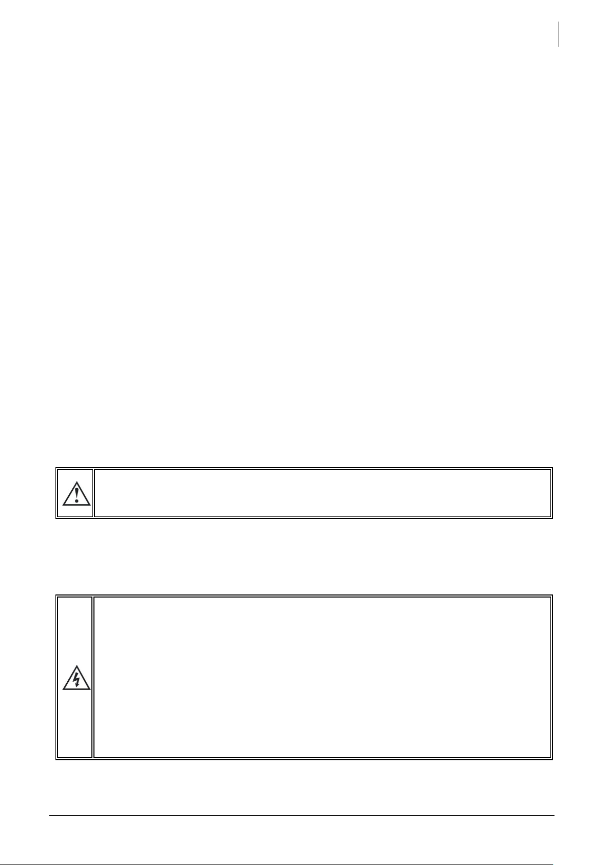
When the Xtender is running, it generates voltage that can be potentially lethal. Work on or
close to the installation must only be carried out by thoroughly trained and qualified
personnel. Do not attempt to carry out on-going maintenance of this product yourself. The
Xtender or the generator connected to it may start up automatically under certain
predetermined conditions.
When working on the electrical installation, it is important to be certain that the source of
DC voltage coming from the battery as well as the source of AC voltage coming from a
generator or network have been disconnected from the electrical installation.
Even when the Xtender has been disconnected from the supply sources (AC and DC), a
dangerous voltage may remain at the outputs. To eliminate this risk you must switch the
Xtender OFF using the ON/OFF button (1). After 10 seconds the electronics is discharged
and intervention may take place without any danger.

Studer Innotec SA
Xtender
User manual V4.5.0 8
All elements connected to the Xtender must comply with the applicable laws and regulations.
Persons not holding written authorisation from Studer Innotec are not permitted to proceed with any
change, modification or repairs that may be required. Only original parts may be used for authorised
modifications or replacements.
This manual contains important safety information. Read the safety and working instructions carefully
before using the Xtender. Adhere to all the warnings given on the device as well as in the manual,
by following all the instructions with regard to operation and use.
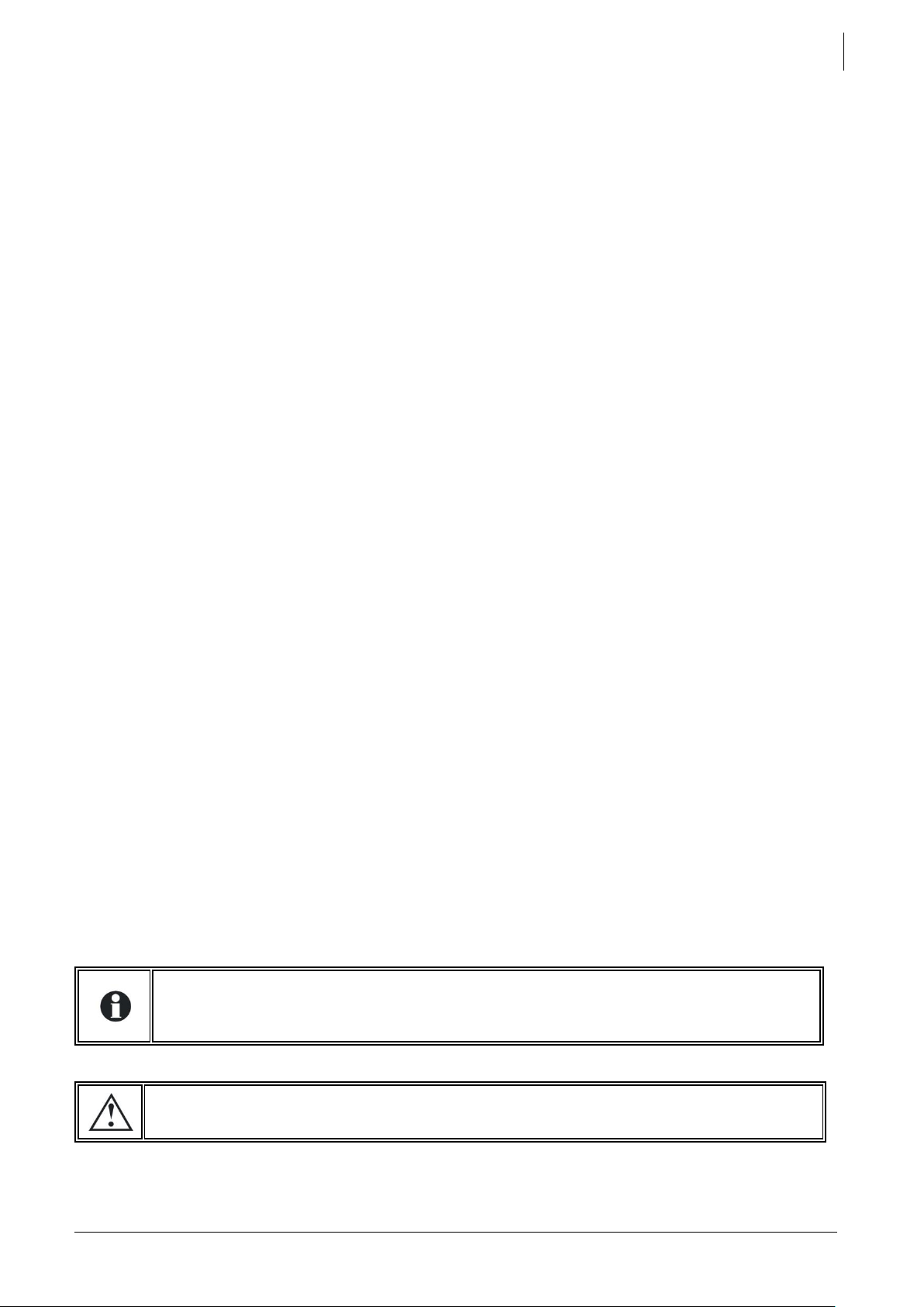
The Xtender, except XTS, is only designed for indoor use and must under no circumstances be
subjected to rain, snow or other humid or dusty conditions. The maximum specifications of the device
shown on the type plate, as at fig. 1b, must be adhered to.
In the event of use in motorised vehicles, the Xtender must be protected from dust, splash water and
any other humid condition. It must also be protected from vibration by installing absorbent parts.
The Xtender can be installed at altitudes up to 3000m. For installations at higher altitudes,
please contact Studer Innotec SA. The Xtender is in overvoltage category III, which
indicates that it can be installed directly after the protection device at the entrance of
a building.
2.4.2 Precautions for using the batteries
The batteries should only be chosen, dimensioned and installed by qualified personnel,
trained in this specific area.
Lead-acid or gel batteries produce a highly explosive gas with normal use. No source of
sparks or fire should be present in the immediate vicinity of the batteries. The batteries
must be kept in a well-ventilated place and be installed in such a way as to avoid
accidental short-circuits when connecting.
Never try to charge frozen batteries.
When working with the batteries, a second person must be present in order to lend
assistance in the event of problems.
Sufficient fresh water and soap must be kept to hand to allow adequate and immediate
washing of the skin or eyes affected by accidental contact with the acid.
In the event of accidental contact of the eyes with acid, they must be washed carefully
with cold water for 15 minutes. Then immediately consult a doctor.
Battery acid can be neutralised with baking soda. A sufficient quantity of baking soda
must be available for this purpose.
Particular care is required when working close to the batteries with metal tools. Tools such
as screwdrivers, open-ended spanners, etc., may cause short circuits. Sparks resulting
from these short-circuits can cause the battery to explode. Therefore, tools with insulated
handles should be used and they should never be left to rest on top of the batteries.
When working with the batteries, all metal jewellery such as rings, watches with a metal
bracelet, earrings, etc., must be taken off. The current supplied by the batteries during a
short circuit is sufficiently powerful to melt the metal and cause severe burns.
Batteries at the end of their life-cycle should be recycled in accordance with directives
from the responsible local authorities or the battery supplier. The batteries should never
be exposed to fire as they may explode. Under no circumstances should you try to take
apart or dismantle the battery, as they contain toxic and polluting materials. For
ungrounded battery systems, always check that they are not inadvertently grounded
before starting work on the batteries.
Always follow carefully the instructions of the battery manufacturer.
Studer Innotec SA
Xtender
User manual V4.5.0 9
3 ASSEMBLY AND INSTALLATION
3.1 HANDLING AND MOVING
The weight of the Xtender can be up to 50kg depending upon the model. Use an appropriate lifting
method as well as help from a third party when installing the equipment.
3.2 STORAGE
The equipment must be stored in a dry environment at an ambient temperature of between
-20°C and 60°C. It stays in the location where it is to be used a minimum of 24 hours before being set up.
3.3 UNPACKING
When unpacking, check that the equipment has not been damaged during transportation and that
all accessories listed below are present. Any fault must be indicated immediately to the product
distributor or the contact given at the back of this manual.
Check the packaging and the Xtender carefully.
Standard accessories:
Installation and operating instructions, c.f. Appendix 1.
Mounting plate for XTH and XTS– fig. 2a (25)(26).
One set of cable glands on the unit and/or apart.
Four M6 screws and washer for XTS to assemble the support and the enclosure.
3.4 INSTALLATION SITE
3.4.1 XTM and XTH
Devices in the XTM and XTH range are designed for indoor use (IP20) and the place of installation
must satisfy the following criteria:
Protected from any unauthorised person.
Protected from water and dust and in a place with no condensation.
It must not be situated directly above the battery or in a cabinet with it.
No easily inflammable material should be placed directly underneath or close to the Xtender.
Ventilation apertures must always remain clear and be at least 20cm from any obstacle that
may affect the ventilation of the equipment.
In mobile applications it is important to select an installation site that ensures as low a vibration
level as possible.
According to the IEC/EN 62109-1 norm, the level of pollution at the mounting place should
not exceed PD2 (second degree environment), which means that there can be pollution as
long as it is not electrically conductive. XTS
XTS range appliances have a high grade of protection (IP54). They can therefore be installed
outdoors, with exposure to dust and water splashes. It is recommended to avoid locations particularly
exposed to salt water splashes which are extremely aggressive (for instance under a vehicle chassis)
or to solvent (motor oil) that can attack all non-metallic parts of the enclosure. Also avoid installing
the XTS in direct sunlight or near a heat source (i.e. engine compartment). The presence of a heat
source may reduce significantly the nominal power of the unit.
Reduce as much as possible exposure to sudden temperature changes as a variation in temperature
may cause undesired condensation inside the enclosure.
The 4 mounting screws of the enclosure must be completely tightened with a torque of
5Nm in order to guarantee the IP 54 protection index. Any unused cable glands should
be closed in a way that guarantees at least the same level of protection.
3.5 FASTENING
The Xtender is a heavy unit and must be mounted to a non-flammable support (wall)
designed to bear such a load
The Xtender must be installed vertically onto heavy duty material (concrete or metallic wall) and
positioned vertically with cable glands oriented down. A sufficient space around it must be provided
to guarantee adequate ventilation of the device (see figs. 2a).
Studer Innotec SA
Xtender
User manual V4.5.0 10
3.5.1 Fastening of the XTH model
First fix the mounting bracket (26)) supplied with the device using 2 Ø < 6-8 mm >screws**.
Then hang the Xtender on the bracket. Fasten the unit permanently using 2 Ø <6-8 mm> screws** on
to the two notches located at the underside of the case.
Dimensions of the appliances are given on Fig 2a of the appendix 1.
3.5.2 Fastening of the XTM model
Screw first the top screw (6-8mm **) without washer on a solid wall (concrete or metallic wall) up to
a distance of 2mm between head and wall. Hang the apparatus by taking care to release
beforehand the trap door of access (27 fig. 2a of the appendix) by inserting it inside the apparatus
using a screwdriver, if you estimate that a complete tightening of this point of fixing is necessary. In
theory complete tightening is necessary only in the mobile installations.
Dismount the lower plastic cap of the apparatus giving access to the compartment of wiring.
Carefully fix the apparatus with two screws (Ø 6-8 mm) in the two clamp holes down inside the
compartment of wiring.
If the Xtender is installed in a closed cabinet this must have sufficient ventilation to guarantee an
ambient temperature that conforms to the operation of the Xtender.
**: These items are not delivered with the device.
It is imperative to ensure complete and safe fastening of the device. A device that is simply
hung may detach and cause severe damage.
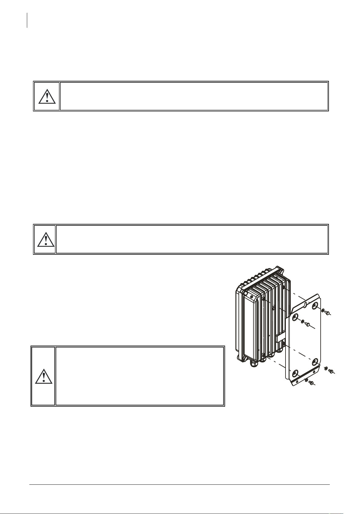
3.5.3 Fastening of the XTS model
The XTS enclosure must be first mounted on the support plate with
the 4 screws and washer delivered with the appliance according
with figure aside. Then the unit can be fixed on a heavy duty
support (concrete or metallic wall) and positioned vertically with
cable glands oriented down. An external ventilation unit (ECF-01,
p. 37 ) can be installed on top of the unit before or after wall
mounting.
A minimum distance of 20 cm in between and/or around the XTH devices is required in
order to guarantee sufficient ventilation.
The envelope of the XTS can reach temperatures higher
than 60°C when used for a long period near its max
power level. These high temperatures may remain
present during several tens of minutes after stopping the
unit. It’s recommended to choose a place of installation
in a restricted access area, away from children or any
unauthorized person.
Studer Innotec SA
Xtender
User manual V4.5.0 11
3.6 CONNECTIONS
3.6.1 General recommendations
The Xtender falls within protection class I (has a PE connection terminal). It is vital that a protective
earth is connected to the AC-In and/or AC-Out PE terminals. An additional protective earth is
located at the bottom of the unit (See sect 3.6.4 – p. 11/13, tag (17)).
In all cases, the PE conductor for the equipment must at least be connected to the PE for
all equipment in protection class I upstream and downstream of the Xtender (equipotential
bonding). It is mandatory that the legislation in force for the application concerned be
adhered to.
Tighten of the input (13) and output (14) terminals by means of a no. 3 screwdriver (minimum 1.2 Nm
tightening torque) and those for the “Command entry (REMOTE ON/OFF”) (7) and “AUX.CONTAC”
(8) by means of a no. 1 screwdriver (0.55 Nm tightening torque).
The cable cross-sections of these terminals must conform to local regulations.
All connection cables as well as the battery cables must be mounted using cable restraints in order
to avoid any traction on the connection.
Battery cables must also be as short as possible and the cross-section must conform with the
applicable regulations and standards. Sufficiently tighten the clamps on the “battery” inputs (fig. 4a
(11) and (12) (10 Nm tightening torque).
Before connecting or disconnecting the entry or exit cables AC-in (13) and AC-out (14), the
installer must make sure that there is no voltage present in the cables OR on the teminals.
Before connecting the battery, the installer must make sure that the AC-in source and the
AC-out loads are well disconnected.
Studer Innotec SA
Xtender
User manual V4.5.0 12
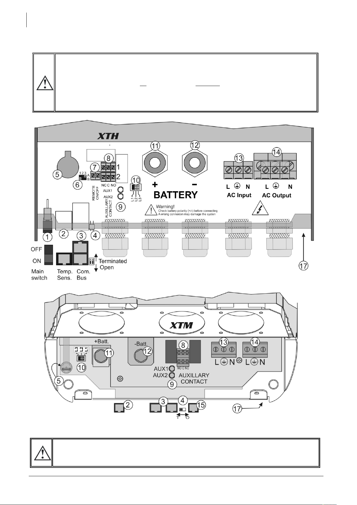
3.6.2 Device connection compartment XTH - XTM
The unit’s connection compartment must remain permanently closed when in operation.
It is imperative to close the protection cap on the connection terminals after each
intervention in the device.
After opening, check that all sources of AC and DC voltage (batteries) have been
disconnected or put out of service.
Some accessible part inside the compartment can have surface temperature higher than
60°C. Wait for the complete cooling of the unit before opening the compartment.
Any unused cable entry on the device must be sealed so as to prevent any intrusion. An
intrusion of small animals in the unit may cause serious damage not covered by warranty.
Studer Innotec SA
Xtender
User manual V4.5.0 13
3.6.3 Device connection compartment XTS
Any unused cable entry on the device must be sealed so as to prevent any intrusion. An
intrusion of small animals in the unit may cause serious damage not covered by warranty.
Studer Innotec SA
Xtender
User manual V4.5.0 14
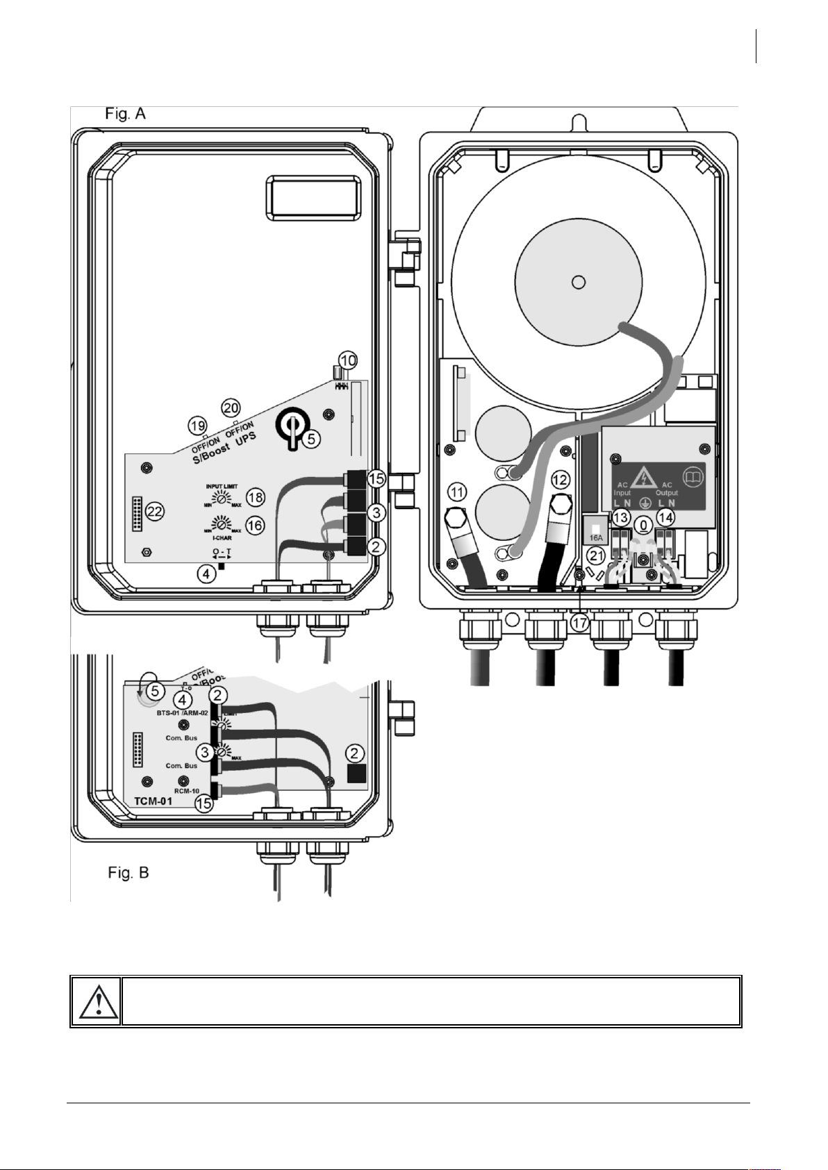
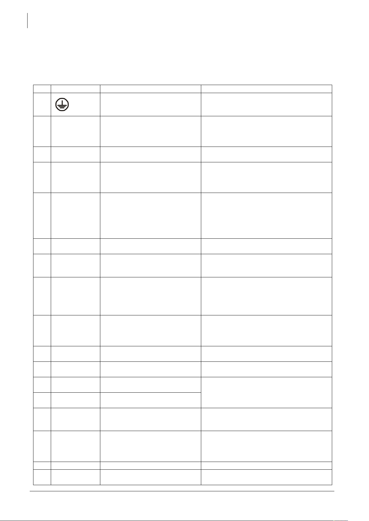
3.6.4 Elements of connection cabinet
Note: The left part of figure A shows the positions of elements (2, 3, 4, 5 and 15) as placed in recent
devices. Figure B shows the positions of elements 2, 3, 4, 5 and 15 as placed on the communication
module TCM-01 present in older versions of the device and described in chapter 9.4.
The functionalities of the device are identical in both configurations.
Pos.
Denomination
Description
Comment
0
Protective earth connection
terminal
This terminal is used as primary earth
connection protection. (see chapter.
3.6.1– p. 11)
1
ON/OFF
Main switch
Main on/off switch
See sect. 11.1 – p. 39.
In XTM and XTS series, this function is
deported on the remote command
module RCM-10. See sect. 9.3 – p. 36.
2
Temp. Sens
Connector for the battery
temperature sensor
See sect. 9.2 – p. 36. Only connect the
original Studer BTS-01 sensor.
3
Com. Bus
Double connector for
connecting peripherals such as
the RCC-02/03 or other
Xtender units
Only Studer compatible device can be
connected. The connection of any other
device (LAN etc.) may damage the
device. See chapter 4.5.9 – p. 23.
4
O / T
(Open /
Terminated)
Switch for terminating the
communication bus.
Set position (open) if the 2
connectors (3) are occupied.
Set position T if only one is
occupied.
On model XTH the 2 termination switches
(4) must be in the same position: either
both in position O (open) or both in
position T (terminated).
5
--
3.3 V (CR-2032) lithium ion type
battery socket
Used as a permanent supply for the
internal clock. See sect. 7.6 - p. 31.
6
--
Jumper for programming the
off/on switch by dry contact
See sect. 7.7 – p. 31 and fig. 8b point (6)
and (7). They are positioned at A-1/2 and
B-2/3 by default.
7
Command
entry
(REMOTE
ON/OFF)
Entry command terminals.
In XTM series, this entry is
deported on the remote
command module RCM-10.
See sect. 9.3 – p. 36
Allows the control of a function – to be
defined by programming – by the closing
of a dry contact or by the presence of a
voltage across these terminals. See sect.
7.7 – p. 31).
8
AUXILLARY
CONTACT
Auxiliary contact
For XTS model, available only
with module ARM-02 (see sect.
9.5 - p. 37
(See sect. 7.5 – p. 31)
Take care not to exceed the admissible
loads.
9
--
Activation indicators for
auxiliary contacts 1 and 2
See sect. 7.5 – p. 31.
10
L1/L2/L3
Phase selection jumpers.
See sect. 8.1. – p. 33.
Jumper default at position L1.
11
+BAT
Positive pole battery
connection terminals
Carefully read sect. 4.5 – p.19
Take care with the polarity of the battery
and when tightening the clamp.
12
-BAT
Negative pole battery
connection terminals
13
AC Input
Connection terminals for the
alternative power supply
(generator or public network)
See sect. 4.5.7 - p. 23.
Note: It is imperative that the PE terminal
be connected.
14
AC Output
Connection terminals for the
device output.
See sect. 4.5.6 - p. 23.
Note: Increased voltages may appear
on the terminals, even in the absence of
voltage at the input of the inverter.
15
RCM-10
Connector for RCM-10 module
Only on XTM and XTS. See sect. 9.3 – p. 36
16
I-CHAR
Rotating knob to adjust the
battery charge current
Only in XTS model.
Studer Innotec SA
Xtender
User manual V4.5.0 15
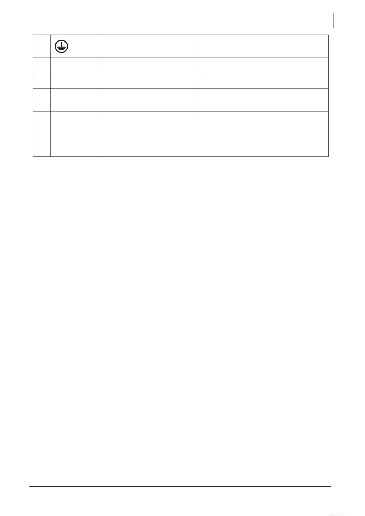
17
Connection for supplementary
protective earth.
This connection can also be used as
principal protective earth. See sect.
3.6.1– p. 11.
18
INPUT LIMIT
Rotating knob to adjust the
input current limit
Only in XTS model. For other models, see
sect. 7.2.2 – p. 27.
19
OFF/ON
S/Boost
Activation of source assistance
“Smart boost” function
Only in XTS model. For other models, see
sect. 7.2.2.4 – p. 28.
20
OFF/ON
UPS
Setting of sensitivity of the
detection of AC input loss:
OFF=tolerant / ON=Fast
Only in XTS model. For other models, see
section. 7.2.1 – p. 27.
21
16A
AC input protective device: Only on XTS model. This protective device will
trip in case of excessive load when the XTS is connected to an
unprotected source higher than 16A.
It can be reset after removing the default downstream (load too high) and
upstream (source greater than 16A. (check the unit is connected thru an
upstream protective device (fuse or circuit breaker) max. 16 A.
Studer Innotec SA
Xtender
User manual V4.5.0 16
4 CABLING
The connection of the Xtender inverter / charger is an important step of the installation.
It may only be carried out by qualified personnel and in accordance with the applicable local
regulations and standards. The installation must always comply with these standards.
Pay attention that connections are completely tightened and that each wire is connected at the
right place.
All cables must be insulated. The IEC/EN 62109-1 norm states requires that the cables must be
insulated with PVC, TFE, PTFE, FEP, neoprene or polyimide.
4.1 CHOICE OF SYSTEM
The Xtender may be used in different system types, each of which must meet the standards and
particular requirements associated with the application or site of installation. Only an appropriately
qualified installer can advise you effectively on the applicable standards with regard to the various
systems and the country concerned.
Examples of cabling are presented in appendix I of this manual, fig. 5 and following. Please carefully
read the notes associated with these examples in the tables on p. 33 and following.
4.1.1 Hybrid type stand-alone systems
The Xtender can be used as a primary supply system for off- grid sites where a renewable energy
source (solar, wind or hydraulic) is generally available and a generator is used as backup. In this case,
batteries are generally recharged by a supply source such as solar modules, wind power or small
hydropower systems. These supply sources must have their own voltage and/or current regulation
system and are connected directly to the battery. (Example, fig. 11)
When the energy supply is insufficient, a generator is used as a back-up energy source. This allows
the batteries to be recharged and direct supply to consumers via the Xtender transfer relay.
4.1.2 Grid-connected emergency systems
The Xtender can be used as an emergency system, also known as an uninterruptible power supply
(UPS) – enabling a reliable supply to a site connected to an unreliable network. In the event of an
interruption to the energy supply from the public network, the Xtender, connected to a battery,
substitutes the faulty source and enables a support supply to the users connected downstream. These
will be supplied as long as the energy stored in the battery is sufficient. The battery will quickly be
recharged at the next reconnection to the public grid.
Various application examples are described in figs. 8a – 8c in appendix 1.
4.1.3 Integrated mobile systems
These systems are meant to be temporarily connected to the grid and ensure the supply of the
mobile system when this is disconnected from the grid. The main applications are for boats, service
vehicles and leisure vehicles. In these cases, two separate AC inputs are often required, one
connected to the grid and the other connected to an on-board generator. Switching between two
sources must be carried out using an automatic or manual reversing switch, conforming to the
applicable local regulations. The Xtender has a single AC input.
Various application examples are described in figs. 10a – 10b – 10c.
4.1.4 Multi-unit systems
Whatever system is selected, it is possible to realise systems composed of several units of the same
type and the same power output. Up to three Xtender in parallel or three extenders forming a threephase grid or three times two or three Xtender in parallel forming a three-phase / parallel grid, may
be thus combined.
The use of the Xtender as a UPS must be carried out by qualified personnel who have been
checked by the responsible local authorities. The diagrams in the appendix are given for
information and as a supplement. The applicable local standards and regulations must be
adhered to.
Studer Innotec SA
Xtender
User manual V4.5.0 17
4.1.5 Distributed Minigrid
The implementation of the Xtender on top of a distributed minigrid (beyond the main building)
requires special care in choosing the distribution system.
Studer Innotec recommends a TT distribution for the DC grid as well as for the AC grid.
The size of the grid increases greatly the exposure of the inverters to atmospheric
overvoltage and to non equipotentiality in the grid. This is particularly noticeable in the aerial
distribution grids. In this case very special care must be taken to implement correctly all
protection measures of the installation.
4.2 EARTHING SYSTEM
The Xtender is a protection class I unit, which is intended for cabling in a grid type TT, TN-S or TNC-S.
The earthing of the neutral conductor (E) is carried out at a sole installation point, upstream of the
RCD circuit breaker (D) type A, 30 mA.
The Xtender can be operated with any earthing system. In all cases it is imperative that the protective
earth be connected in compliance with the applicable standards and regulations. The information,
notes, recommendations and diagram mentioned in this manual are subject to local installation
regulations in every case. The installer is responsible for the conformity of the installation with the
applicable local standards.
4.2.1 Mobile installation or installation connected to the grid via plug
connector
When the input of the device is connected directly to the grid via a plug, the length of the cable
must not exceed 2 m and the plug must remain accessible.
In the absence of voltage at the input, the neutral and live are interrupted, thereby guaranteeing
complete isolation and protection of the cabling upstream of the Xtender.
The earthing system downstream of the Xtender is determined by the upstream earthing system when
the grid is present. In the absence of the grid, the earthing system downstream of the inverter is in
isolated mode. The safety of the installation is guaranteed by the equipotential bonding.
The connection (link) between the neutrals (C) upstream and downstream of the Xtender
is not permitted in this configuration.
This connection type guarantees the optimal continuity for supplying the Xtender loads. The first
isolation fault will not lead to an interruption in the supply.
If the installation requires the use of a permanent isolation controller this would have to be deactivated when the TT network is present at the Xtender input.
All sockets and protection class I devices connected downstream of the Xtender must be
properly connected to the earth (earthed socket). The cabling rules above remain valid,
including in installations, in all cases where the Xtender input is connected to the grid via a
plug connector.
The IT system is not recommended for the distribution. This kind of distribution is most of the
time forbidden by the local laws. The achievement of low voltage electric system is always
subject to local laws and must imperatively be implemented and controlled by qualified
and professionally authorized staff. Studer Innotec accepts no liability for damages due to
non-conforming installation and to the lack of compliance with the local rules or with the
recommendations of this manual.
 Loading...