

Studer Vista 8
Digital Audio Console Information
29th July 2004

1 INTRODUCTION............................................................................................................ 3
2 GENERAL SYSTEM OVERVIEW ............................................................................... 3
2.1 S
YSTEM BLOCK DIAGRAM .......................................................................................... 3
2.1.1 Block Diagram showing system utlising D21m IO System ................................ 3
2.2 CONTROL SURFACE (VISTA 8)..................................................................................... 4
•
Momentary/Latching Activation of all Buttons .......................................................... 5
•
Ganging ...................................................................................................................... 5
•
Fast Copy/Paste and Half-Lit Keys............................................................................ 5
•
Banking with Scrolling Navigation ............................................................................ 5
2.3 DSP CORE................................................................................................................... 6
2.4 I
NPUT/OUTPUT SYSTEM .............................................................................................. 7
2.4.1 Available D21m Audio IO Cards ....................................................................... 7
2.4.2 D21m Stagebox System ...................................................................................... 7
2.5 MONITORING, TALKBACK AND SIGNALLING ............................................................... 8
2.5.1 Monitoring.......................................................................................................... 8
2.5.2 Talkback and Signalling..................................................................................... 8
2.6 EXTERNAL SYNCHRONISATION ................................................................................... 9
3 TROUBLESHOOTING................................................................................................... 9
3.1 SYSTEM SURVEYOR..................................................................................................... 9
3.2 SERVICE ISSUES......................................................................................................... 10
4 REDUNDANCY ............................................................................................................. 11
4.1.1 Power Supplies................................................................................................. 11
4.1.2 DSP Core.......................................................................................................... 11
4.1.3 MADI Links ...................................................................................................... 12
4.1.4 Control System ................................................................................................. 12
4.1.5 Control Surface ................................................................................................ 12
4.1.6 Mastersync Unit ............................................................................................... 13
4.2 N-1 DESCRIPTION ..................................................................................................... 13
5 TECHNICAL SPECS .................................................................................................... 14
5.1 VISTA 8 CONTROL SURFACE DIMENSIONS ................................................................ 14
5.2 P
OWER CONSUMPTION .............................................................................................. 14
2
1 Introduction
This document outlines some of the key features of the Studer Vista 8 Digital Audio Console.
2 General System Overview
The system structure of the Vista 8 Digital Console can be separated into 5 main areas:
1. Control Surface
2. DSP Core
3. IO
4. Monitoring & Signalling
5. External Synchronisation
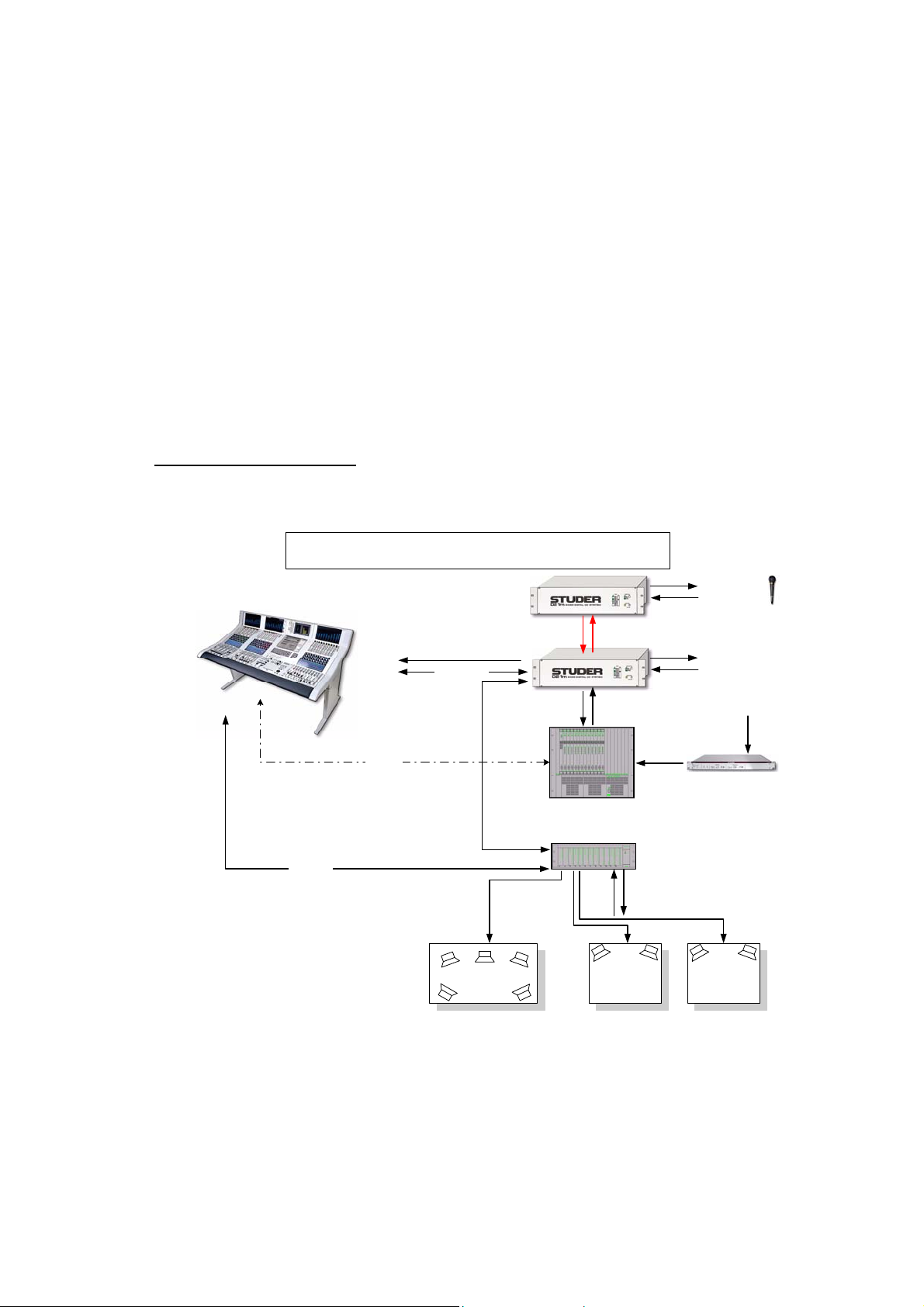
2.1 System Block Diagram
2.1.1 Block Diagram showing system utlising D21m IO System
Global Wiring Overview Vista 8 (with D21m I/O)
Vista 8 Desk (with built-in Cont rol System)
RS485/HP/TB
Optical Link
D21m Stagebox
Option: Outputs for Custom
Meters
Mic Control Data
AES/EBU Link
AES/EBU Link
Control Room
Monitoring 5.1
D21m Hub
TB Int
PFL/CR/ST
MADI (with embedded Mic Control)
LVDS (CAT 5)
DSP Core
Monitoring Frame
48 GPI
32 GPO
Studio A
Monitoring
2Ch
(optional)
Stagebox IO
Local IO
House Sync
(Video, Wordclock, etc)
(Option: Mastersync Unit)
Studio B
Monitoring
2Ch
(optional)
PLEASE NOTE: This is a general System Block Diagram. Actual number of D21 IO frames
will depend on customer requirements.
3
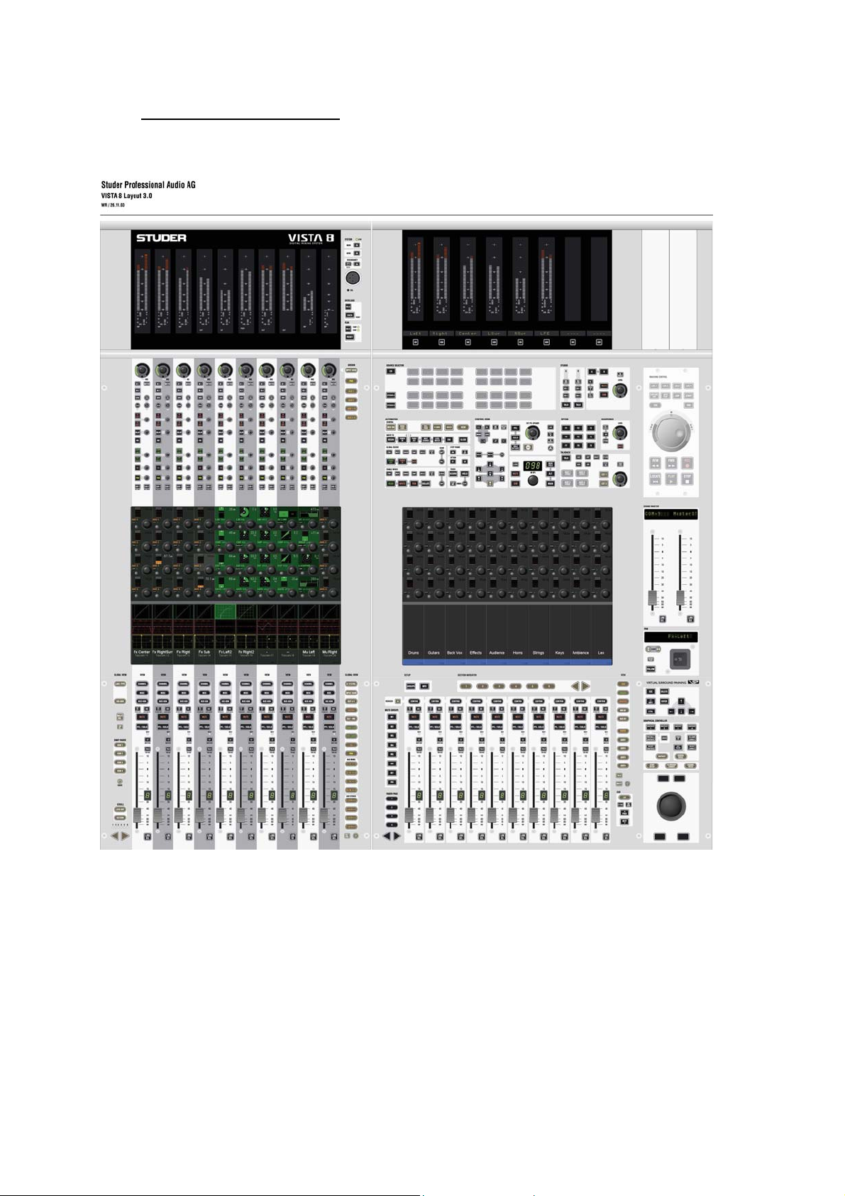
2.2 Control Surface (Vista 8)
The Control Surface of the Vista 8 is shown below (only 1 fader bay shown):
The control surface features the industry acclaimed Vistonics User Interface which offers a
“where you look is where you control” philosophy. The Studer developed Vistonics
technology mounts rotary controls and switches on TFT Screens. This then offers the user the
benefits of screen technology (Touchscreen, colour, icons and text) without the limitations of
having to access physical controls away from the where the control is displayed. A touch and
access philosophy combined with Channel strip orientated operation offers a friendly and
intuitive operating concept.
4

This extremely intuitive and fast to learn operational concept is further enhanced by 4 other
key operational features that frees the users mind from working on the console and allows
more thought to be placed on the work at hand. These key features are:
• Momentary/Latching Activation of all Buttons
The console recognizes and senses the button-push duration and responds accordingly. The
buttons therefore act momentarily or latchingly depending on how they were pressed (pressedand-held or briefly tapped). In addition to Talkback, PFL, EQ on/off, etc., the functions affected
include those accessed by the touch-screen - such as viewing of audio function - as well as the
monitoring source selectors and the machine control.
• Ganging
The ganging function in the mixer allows the operator to quickly apply functions to multiple
channel strips because channels within the gang act as one. This can be used, for example, for
Mute, Automation mode changes, faders, Bus assign and much more to increase speed and
comfort in operation. Creating a gang over the console makes the set-up quick and easy.
• Fast Copy/Paste and Half-Lit Keys
The console incorporates dedicated copy/paste keys for each audio function including EQ,
dynamics, panorama and delay. A simple button-press in the original channel and another in
the target channel copies the settings across. Copy/Paste is guided up by the half-lit buttons: if
one button has been pressed and the desk is awaiting a second button-press, all available
target buttons illuminate at half brightness until one of them has been selected. Also, complete
channels can be cloned to one or many target channels. Setting up the Studer Vista 7 for a
production becomes a quick and easy task. Non-productive time is reduced considerably.
• Banking with Scrolling Navigation
DSP channels not visible on the physical desk are accessed by scrolling the channels available in the
DSP core. The channel order is freely assignable: channels can be grouped or even shown repeatedly
on the surface. This ensures physical orientation on the desk so that the operator is always clearly
informed as to what is happening. Channel Bays with, for example, the master channels can also be
locked in place.
The Vista 8 also includes a completely redesigned Control Bay. While talkback and monitoring
functionality, trackball and a motorized joystick have been maintained from the previous Vista
consoles, dedicated control elements have been introduced for operation of outputs. 12 motorized
5

faders and a Vistonics™ screen with 40 rotaries have been added. Multiple user definable assignments
of these 12 faders and Vistonics™ controls are possible to be recalled by one button press, giving up
to 52 directly accessible level controls for controlling all sorts of outputs such as master, groups or
matrix outputs. Two of the faders will act as “grand masters” without alternate pages, allowing instant
influence on all console outputs if needed. The other 10 fader strips as well as all 40 rotaries with their
pushbuttons will allow also SOLO/PFL, MUTE as well as TALKING to each masters individually.
Metering has also been extended: 40 meters are visible on the Vistonics and the corresponding level
controls are immediately available on the rotary controls next to them. Looking at levels and
correcting them therefore is just a fraction of a second away.
Another major improvement is the “reverse operation” of masters and their busses. Vista 8 can show
all channels contributing to a specific master bus on the Vistonics™ screen and allows level
adjustment of all those channels instantly - without physically accessing the contributing channels
themselves on the fader bay.
Furthermore the control group functionality (VCA style) will be extended to form control groups with
different levels of control (hierarchical control groups). Each channel strip allows the possibility to flip
a single fader to a second layer without flipping the whole console. Dynamic Automation is also a
feature of the desk. You can boot the desk in one of two modes; Snapshot automation for live on-air or
dynamic automation for production use. New dual colour metering is provided on each channel to give
better headroom indication which is definable.
2.3 DSP Core
The DSP core of the Studer Vista 8 builds on Studer‘s well-proven digital technology. It incorporates
an excellent reliability record and inspires a high degree of confidence enjoyed by the numerous users
operating systems in mission-critical applications. The DSP core uses parallel processing architecture
with integrated floating point circuitry and an internal word length of 40 bits. No overloads will ever
occur within the console, since floating point architecture is even used in the summing busses. The
system can be used in 48 kHz or 96 kHz mode.
The DSP Core is based on modular cards and the more DSP cards that have been fitted in the core, the
more DSP power is available. DSP Boards can have 8 AES IO incorporated per board.
An offline Configuration Editor tool is also available which allows the available DSP Power to be
reconfigured by the customer. This includes changing the number of channels, audio processing and
bussing structure of the console for a particular project. Extensive import functions allows the user to
adapt existing configurations to meet changing needs. In addition, the combination of modular DSP
cards and the configuration editor means that future console expansion is as simple as adding more
DSP cards and making new larger configurations with the configuration editor.
6

2.4 Input/Output System
The D21m high-density audio interface system is like a hub to the Vista 8 DSP Core. The 19” Frame
can hold up to 12 interface cards where audio is collected from or distributed to all standard
professional industry audio formats.
Up to 384 inputs and outputs from 12 audio card slots are collected in the center of the 3U D21m
Frame where one or two High Density Cards can be placed. These cards provide the link to the DSP
Core of the console using standard CAT 5 cable connections. Each connection carries up to 96
channels into the Performa DSP Core and 48 channels out in 24 bit 96Khz quality. The system
automatically detects newly inserted cards and assigns the appropriate number of Input/Output
channels to it. A status display on the front panel informs the user if a card is present or if the card has
failed or been removed. The Frame may also be ordered with redundant power supplies. In addition,
all D21m audio cards are hot-pluggable.
2.4.1 Available D21m Audio IO Cards
• Microphone Card: 4 x microphone Preamp with 24 bit Converter (split output available as
standard)
• AES/EBU Card: 8 x AES/EBU in and 8 x AES/EBU Out
• AES/EBU Card with Input and Output SFC: Same as above but with asynchronous
sampling Frequency converters on both inputs and outputs.
• Line In Card: 8 channel D/A Converter Board (Specs?)
• Line Out Card: 8 channel A/D Converter Board (Specs?)
• ADAT Card: 2 optical input and 2 optical output interfaces
• TDIF Board: 2 TDIF Interfaces
• MADI IO Board: 1 x 56 or 64 channel MADI Input and Output. A Second input and output
is available and can be used as a redundant MADI or to provide a split MADI signal of Output
1.
2.4.2 D21m Stagebox System
The D21m Stagebox system utilises a D21m Hub which sits local (10m) to the DSP Core and
stageboxes which collect all the remote IO signals and convert them to a single 56 or 64 channel
MADI signal. The Hub then receives the MADI signals from the stageboxes and sends them to the
DSP core via a single CAT 5 cable. The hub can handle up to a maximum of 6 stageboxes. A D21m
Hub can also handle any of the local IO. Any stageboxes with Microphone Preamp cards will require
some control data from the Vista Control Surface. This control data is first sent to the D21m Hub
where the control data is merged with the MADI stream. The system can automatically detect
stageboxes with microphones and send the correct Control Data from the desk making operational
handling incredibly simple. This auto detection mechanism means that sharing stageboxes between
different Consoles is extremely easy requiring no user administration.
7
2.5 Monitoring, Talkback and Signalling
A single 3U rack unit is utilised for housing all of the Monitoring and Signaling cards of the system.
2.5.1 Monitoring
The monitoring is controlled in the analogue domain. Some fixed AES/EBU outputs are utilized from
the Vista 8 DSP Core and are fed to converters built into the monitoring frame. 5.1 monitoring is
standard on the Vista 8 with Dolby EX Monitoring as an option. The Control Room monitoring
section on the control surface provides control of up to three different speaker systems (Two multichannel and one stereo) and 76 source selectors. All internal digital sources can be assigned to any of
the source selector keys as mono, stereo or multichannel sources. The 2 Studio Monitors are
configurable in the same way as the CR Monitor section, although as standard only stereo studio
loudspeaker feeds are supported. Surround studio feeds are available with a custom monitoring frame.
A headphone socket is also available on the control surface for use in the control room.
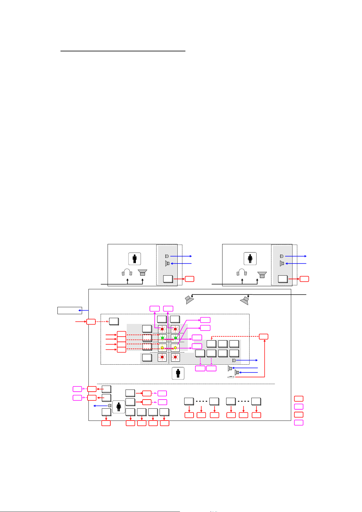
2.5.2 Talkback and Signalling
An extensive talkback system is implemented within the Vista. The talkback source can either be the
built in desk operator microphone or an external producer microphone. Several destinations, such as
buses, direct outs, auxillaries, groups and master outputs are available on block. The block diagram
below shows the talkback and signaling possibilities of the Vista 8.
Talkback and signaling blockdiagram
e.g.Intercom
GPO 5
GPO X
Studio MonitorA
Control Room
Ext 3
(always on)
GPI X
Talk to
GPI11
EXT1
Talk to
GPI12
EXT2
Mic "TB2"
Talk to
preselected
GPI 6 GPI 7 GPI 8 GPI 9 GPI 10
On Air
Vista6 Desk
GPI 3
GPI X
GPI 4
GPI X
Producer
e.g.Speaker
Signaling Keys
Talk to
Studio
A
Talk to
Studio
B
Talk to
Aux1
Studio A
Talk to
GPI 5
GPI X
Talk to
Aux2
SIG1
SIG2
Studio
Ext Location 1
Ret 1
(Line level)
Ext 1
Talk to
CR
(-> to PFL Speaker)
GPO 0
GPO X
Selector
StudioA
Red
Light
GPO 3
GPO X
Talk to
Talk to
Aux3
Aux4
GPI 1
Selector
StudioB
Desk
Operator
Producer area (either in control room or in another room)
GPO 1
GPO 2
Talk to
Ext1
TB Keys
GPO 4
Talk to
ChanOut
Grp01
GPI X GPI X GPI X GPI XGPI XGPI X
GPO X
GPO X
GPO X
Talk to
preselected
Talk to
Ext2
CR Monitor
Talk to
ChanOut
Grp N
Talk to
Aux1
Talk to
Aux3
Studio Monitor B
Talk to
Aux2
Talk to
Aux4
PFL/TB Out
Footswitch
Channel
Mute
Grp01
TB only
TB Mic
e.g.Speaker
Studio B
Channel
Mute
Grp N
GPI 0
Ext Location 2
Ret 2
Talk to
CR
(-> to PFL Speaker)
Ext 2
GPI 2
Legend :
= GPI already configured in .ini files
GPI 1
= GPO already configured in .ini files
GPO 2
= GPI prepared to use, but not
assigned to signaling card.
GPI X
This can be configured in .ini files
= GPO prepared to use, but not
assigned to signaling card.
GPO X
This can be configured in .ini files
8

2.6 External Synchronisation
External digital synchronization of the console is provided by a Studer Mastersync Unit. This
single 19 inch 1U unit will allow the console to be synchronized to an external video black
burst, wordclock or AES signal.
A second mastersync unit may be used as a redundant unit with an automatic switchover
should a problem occur with the first unit.
3 Troubleshooting
3.1 System Surveyor
The software graphical controller has a built in real/time system surveyor. This surveyor
monitors the status of all of the communication between the various parts of the system and
provides a visual indication to the user of the status. This is extremely re-assuring for the user
who not only has a continuous visual performance indication, but if there is a problem,
clicking on the icon will show the user where problems have occurred. See the screenshot of
the surveyor window below. It also surveys all of the IO racks and displays the status of each
individual IO Card and Power supply in the D21m Frames.
9

This is also extremely useful for service issues. A log file is also kept which logs any system
errors. In some instances, this can then be sent to the factory (via e-mail) for fault finding
assistance.
3.2 Service Issues
As far as the control surface is concerned, each bay is a single module which opens up like a
car bonnet to access inside the console (See picture). All cable connections to the control
surface are on the front of the console for easy access.
The DSP, IO and monitoring are all made up of have modular cards.
10

4 Redundancy
There are 5 areas where redundancy is available:
Power supplies
DSP Core
MADI Links
Complete Control System
Control Surface
Mastersync Unit
4.1.1 Power Supplies
Without exception, throughout all parts of the system redundant power supplies that
automatically switch in case of failure of the primary supply are provided. This includes:
Control Surface
DSP Core
Monitoring
All I/O Frames
Control System (Installed as standard)
4.1.2 DSP Core
The DSP Core is the audio heart of any Digital Mixing Console and therefore if a problem is
to occur in this part of the system, it will usually result in some audible problems. It is
therefore essential that some redundancy is available to ensure continuous and seemless audio
even in the event of failure of part of the DSP Core.
The Studer Vista 8 DSP core is based on mature technology with over 250 broadcast consoles
worldwide utilising the DSP core in round the clock use. The design of the Vista 8 DSP Core
provides seemless audio flow with no disruption to the operator in the case of a DSP Card
failure. Both the physical design and DSP architecture mean that, assuming a redundant card
is available in the DSP Core, the redundant card will instantly take the role of a failed card
with a worse case scenario of a small mute in audio. A failed card may then be physically
replaced with a new card in a hot pluggable manner, again once installed assuming the role of
a redundant card. The replaced DSP card is auto detected in the system with no need for
reboot of any part of the system. If a DSP card is to fail, the worst case scenario in terms of
audio is a small mute (less than 1 sec) and the operator is simply informed of the failure by a
pop up window in the Graphic Controller. In terms of operation, the user is not affected and
can continue undisturbed.
The amount of redundancy is dependent on the number of ‘idle’ cards that are available in the
DSP core and this in turn is dependent on the configuration
1
that is currently loaded. If two
DSP cards lay idle, then this gives the possibility for two cards to fail without interruption.
11

It should be mentioned that if a DSP Card with AES inputs and outputs fails, the processing
will automatically switch but the 8 AES IO for that card, however will still be hardwired to
the failed card. This would mean the loss of the IO signals which were connected to the failed
card although the DSP processing will still swap to the redundant card.
It should also be noted, the DSP Core configuration is stored within the DSP Core itself. This
means that in the rare event of a problem with the Control System, audio will pass through the
DSP Core. In fact, the control system need not be running at all for audio to pass through the
DSP Core. The other advantage of this is that audio passes through the DSP Core in a matter
of seconds from DSP Core Power up.
4.1.3 MADI Links
Every IO frame with a MADI Link can have a second redundant MADI link which would
switch automatically if an invalid MADI signal is received.
4.1.4 Control System
The Control System is central to the communication and control of the different parts of the
system. For this reason, redundant Power Supplies and Raid 0 removable hard drives are
fitted as standard.
A second, fully equipped Control System housed underneath the console is available as an
option offering full 100 % redundancy and peace of mind. The user has the ability to switch to
the redundant Control System for emergency reasons. The data is backed up with an
adjustable time interval and automatically accessed by the redundant System when the
emergency switch is activated. Both Systems can be accessed from the same keyboard. It is
possible to switch GC screen and keyboard/trackball easily back and forth between both
Control Systems. If the emergency switch is activated, the keyboard/trackball/GC is
automatically switched to redundant Control Systems as well. The emergency switch is
located in the meterbridge and must be pressed several seconds in order to activate the
emergency switch. After switching, the user must boot the application from the redundant PC
before he has control. This takes approx 20 seconds. Both Control Systems may be switched
on and off separately, but are normally linked together by a jumper, located within the
meterbridge.
4.1.5 Control Surface
The Control Surface is made up of a number of modular Fader bays. Should one of these bays
fail, all other bays will continue as normal. The concept of navigation allows totally free
allocation of DSP Channels to physical channel strips. In this instance, the user can quickly
and easily re-arrange the strip layout in the Graphical Controller of the control system to reassign the channels that were represented on the failed bay. In addition, the navigation
philosophy allows scrolling of the virtual desk in front of the user. This also provides very fast
navigation in such events.
12

4.1.6 Mastersync Unit
The Mastersync unit provides the clock reference for all parts of the system. The unit can
either synchronise to an external clock or generate it’s own clock. The unit can have two
separate and different clock sources connected to it and will automatically switch to the
redundant input should there be a problem with the primary clock source.
A complete standby mastersync unit is available as an option that will instantly take over
should the main unit have a failure.
4.2 N-1 Description
The N-1 System for the Vista 8 is based on a bussing system. Any number of N-1 busses can
be configured which means that each outside source or telephone hybrid can be assigned to be
the owner of one bus. Any channel on the console can be routed to these n-1 busses (except
the owner to the relevant bus) and assignment is typically pre setup. By using the quick bus
assign functionality, a channel can be quickly de-assigned from a particular bus. All control of
overall level, N-1 On/Off and talkback are provided on the channel itself. In addition it is
possible to adjust the send level of a particular source to all of the n-1 busses. This is
particularly useful for 2 track sources which the outside source wants to hear but at a lower
level. In addition, a bus owner splits its’ input meter for the left hand side of the meter to
show the return level and the right hand side of the meter the N-1 Send.
One further feature of the N-1 system is the ability to send the outside source an off-air signal
whilst waiting to go live. This is achieved by the simple activation of the ‘Alt N-1’ button on
the relevant N-1 owner channel. When the operator opens the fader of the outside source, the
appropriate N-1 bus output is then automatically sent to the outside source without the user
having to manually de-select the off-air signal.
An off-air conferencing (MPX) function is also available allowing any number of outside
sources to talk together whilst off air. When one of the outside sources is put on-air, they are
automatically removed from the conference and fed their correct N-1 bus without operator
intervention.
13
5 Technical Specs
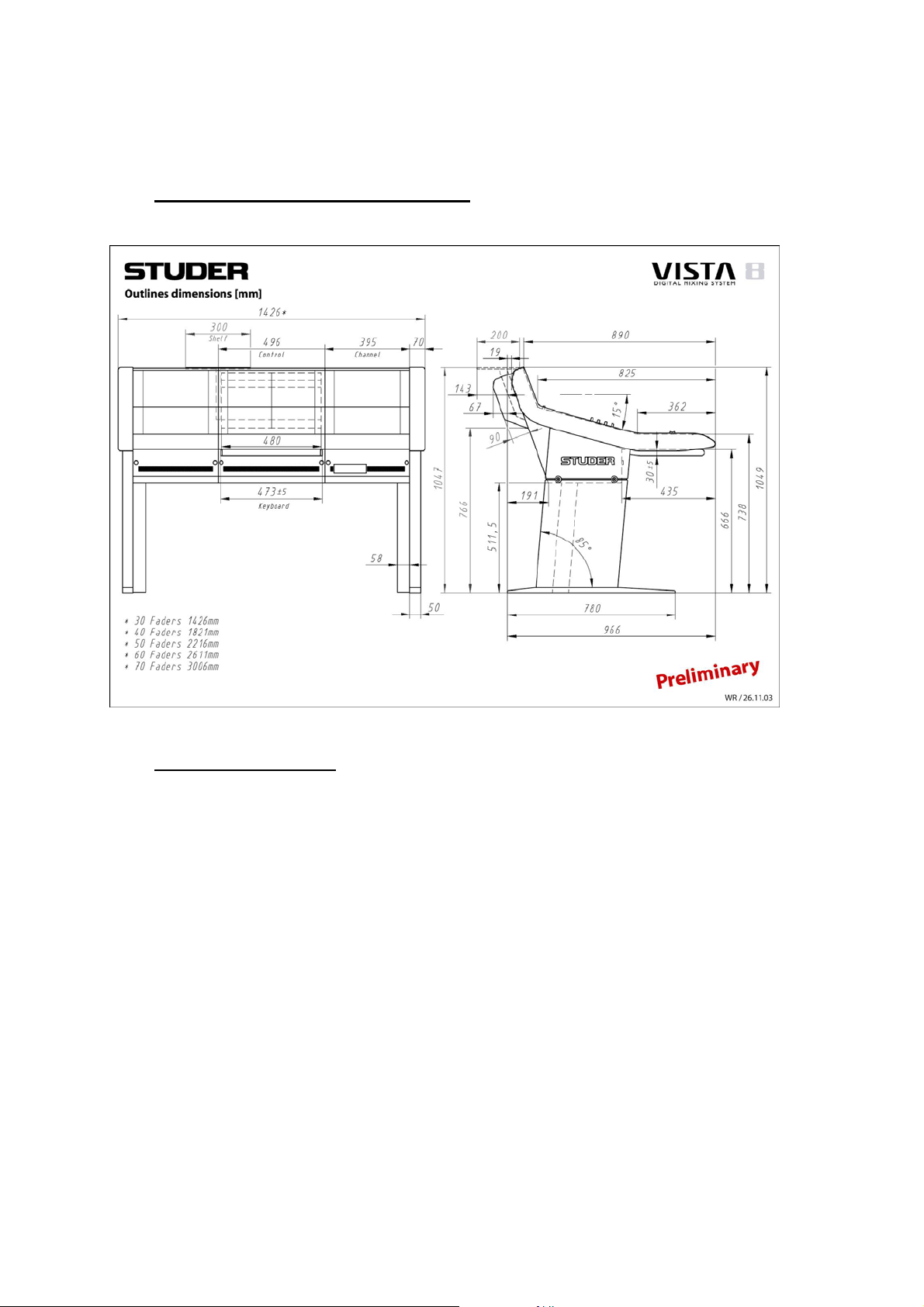
5.1 Vista 8 Control Surface Dimensions
5.2 Power Consumption
Approximate figures
Control Surface:
150W for Control System and Control Bay. 60 Watts in addition per fader bay.
Example: 40 faders (3 fader bays and 1 Control Bay) = 150 + (3x60) = 330W
DSP Core:
20 Processing cards = 800 Watts
Monitoring Frame = 100 Watts
D21m IO Frames = 150W per frame
14
 Loading...