

Page 1

New Features in Nuendo 6.5
Page 2

Cristina Bachmann, Heiko Bischoff, Christina Kaboth, Insa Mingers, Sabine Pfeifer,
Kevin Quarshie, Benjamin Schütte
This PDF provides improved access for vision-impaired users. Please note that due to the
omplexity and num
c
descriptions of images.
The information in this document is subject to change without notice and does not represent
a commitmen
by this document is subject to a License Agreement and may not be copied to other media
except as specifically allowed in the License Agreement. No part of this publication may be
copied, reproduced, or otherwise transmitted or recorded, for any purpose, without prior
written permission by Steinberg Media Technologies GmbH. Registered licensees of the
product described herein may print one copy of this document for their personal use.
All product and company names are ™ or ® trademarks of the
information, please visit www.steinberg.net/trademarks.
© Steinberg Media Technologies GmbH, 2014.
All rights reserved.
t on the part of Steinberg Media Technologies GmbH. The software described
ber of images in this document, it is not possible to include text
ir r
espective holders. For more
Page 3

4 Working with the New Features
4 TrackVersions
16 Instrument Tracks
18 VST Instruments
22 Track Visibility Management
28 Automatic Hitpoint Detection
30 Score Editor Improvements (NEK only)
30 Re-Record Mode
32 ADR
47 Control Room
63 Loudness
73 New Plug-Ins
73 About the New Plug-Ins
Table of Contents
75 Further Improvements
75 Steinberg Hub
75 Drum Maps and VST3 Instruments (NEK only)
76 Track Quick Control Presets
77 Color Management
80 Project Logical Editor Improvements
80 Project Window Improvements
81 MIDI Monitoring Improvements
3
Page 4

Working with the New Features
NOTE
TrackVersions
TrackVersions allow you to create and manage multiple versions of events and parts
on the same track.
TrackVersions are available for audio, MIDI, and instrument tracks. You can also
ve
TrackVersions of the chord track, the signature track, and the tempo track.
ha
TrackVersions are useful for the following tasks:
• Starting new recordings from scratch.
• Comparing different takes and comps.
• Managing takes that were recorded in a
TrackVersions are not available for automation tracks.
TrackVersions are included in track archives and project backups. When you work
with the networking feature, only the active TrackVersion is committed.
The TrackVersion key commands can be found in the TrackVersions category of
m
the Key Com
ands dialog.
TrackVersions Pop-Up Menu
The TrackVersions pop-up menu is available for all track types that support
TrackVersions. It contains the most important functions for managing TrackVersions
and a TrackVersions list.
To open the TrackVersions pop-up men
the track name.
TrackVersion List
Lists all TrackVersions of the track for which you opened the TrackVersions
pop-up
menu and allows you to activate a TrackVersion.
multi-track
u for a track, click the arrow to the right of
recording.
New Version
Creates a new, empty TrackVersion for the selected tracks.
4
Page 5

Working with the New Features
TrackVersions
Duplicate Version
Creates a copy of the active TrackVersion for the selected tracks.
Rename Version
Opens a dialog that allows you to change the TrackVersion name for the
selected tracks.
Delete Version
tes the active TrackVersion for the selected tracks.
Dele
Select Tracks with Same Version ID
Selects all tracks that have a
TrackVersions Inspector Section
The TrackVersions Inspector section allows you to view and manage
TrackVersions for a selected track. It is available for audio tracks, MIDI tracks,
instrument tracks, and the chord track.
TrackVersion with the same ID.
To open the TrackVersions Inspector section for a track, select the track, and in
the Inspector, click the TrackVersions tab.
1) Track Version Indica
In
dicates that more than one TrackVersion exists.
tor
2) Name column
ows the version name. Double-click to change it. The name will be changed
Sh
for all se
lected tracks.
3) ID column
Shows the TrackVersio
n ID.
4) Track Version list
Lists all TrackVersions and allows you to activate one of them for all selected
tracks.
5) New Versi
on
Creates a new, empty TrackVersion for all selected tracks.
5
Page 6

Working with the New Features
PROCEDURE
NOTE
TrackVersions
6) Duplicate Version
Creates a copy of the active TrackVersion for all selected tracks.
7) Delete Version
Deletes the active TrackVersion for all selected tracks. This function is only
i
lable if the track has more than one TrackVersion.
ava
Creating TrackVersions
You can create new, empty TrackVersions for selected tracks.
1. In the track list, select the tracks for which you want to create a new
TrackVersion.
2. Select Project > TrackVersions > New Version.
You can also use the TrackVersions Inspector (only available for audio
tracks, MIDI tracks, instrument tracks, and the chord track) or the
TrackVersions pop-up menu in the track list to create a new TrackVersion.
RESULT
The event display shows a new, empty TrackVersion. Events of previous
kVersions are hidden. The track list shows a default version name.
Trac
ELATED LINKS
R
TrackVersions Inspector Section on page 5
TrackVersions Pop-Up Menu on page 4
6
Page 7

Working with the New Features
PROCEDURE
TrackVersions
TrackVersion IDs
All TrackVersions are automatically assigned an ID. TrackVersions that are created
together get the same TrackVersion ID and can be selected together.
In the TrackVersions Ins
the TrackVersion list.
p
ector, the TrackVersion ID is shown in the ID column of
In the track list, you can open the TrackVersions pop-up menu to see the
TrackVersion ID.
Selecting Tracks by TrackVersion ID
You can simultaneously select all tracks that share the same TrackVersion ID.
1. Activate the desired TrackVersion.
2. Select Project > TrackVersions > Select Tracks with same Version ID.
RESULT
All tracks that have TrackVersions with the same ID ar
7
e selected.
Page 8

Working with the New Features
PROCEDURE
PROCEDURE
TrackVersions
Assigning a Common ID
TrackVersions on different tracks that were not created together have different
TrackVersion IDs. TrackVersions with different IDs cannot be activated together. To
do this, you must assign a new version ID to these tracks.
1. Select the tracks and activate the TrackVersions to which you want to assign
2. Select Project > TrackVersions > Assign Common Version ID.
RESULT
A new ID is assigned to all active TrackVersions on the selected tracks. The tracks
now marked as belonging together. You can now activate them together.
are
a common version ID.
About the Active TrackVersion
If you created more than one TrackVersion for a track, you can show the events of
a specific TrackVersion in the event display. This process is referred to as activating
TrackVersions.
Activating TrackVersions
1. Click the arrow to the right of the track name to open the TrackVersions
pop-up menu.
2. Select the TrackVersion that you want to activate.
RESULT
The selected version is activated and its events are shown in the event display.
8
Page 9

Working with the New Features
NOTE
PROCEDURE
NOTE
PROCEDURE
TrackVersions
If you work with audio tracks, MIDI tracks, instrument tracks, or the chord track, you
can also use the TrackVersions Inspector to activate a TrackVersion.
RELATED LINKS
Activating TrackVersions on Multiple Tracks
You can simultaneously activate TrackVersions on multiple tracks if these
TrackVersions share the same ID.
1. Select all tracks for which you want to activate a specific TrackVersion.
2. Click the arrow to the right of the track name to open the TrackVersions
TrackVersions Inspector Section on page 5
pop-up menu.
3. Select the TrackVersion that you want to activate from the list.
RESULT
The selected TrackVersion is activated for all selected tracks, and the
co
rresponding events are shown in the event display.
If you work with audio tracks, MIDI tracks, instrument tracks, or the chord track, you
can also use the TrackVersions Inspector to activate a TrackVersion.
Duplicating TrackVersions
You can duplicate a TrackVersion by creating a new TrackVersion that contains a
copy of the active TrackVersion.
1. In the track list, select the tracks and activate the TrackVersion that you want
to duplicate.
9
Page 10

Working with the New Features
NOTE
PROCEDURE
NOTE
TrackVersions
2. Select Project > TrackVersions > Duplicate Version.
In the event display, a duplicate TrackVersion is displayed. In the track list, a default
version name for the duplicate is shown.
You can also use the TrackVersions Inspector (only available for audio
tracks, MIDI tracks, instrument tracks, and the chord track) or the
TrackVersions pop-up menu in the track list to duplicate a TrackVersion.
RELATED LINKS
TrackVersions Inspector Section on page 5
TrackVersions Pop-Up Menu on page 4
Deleting TrackVersions
You can delete the active TrackVersions for the selected tracks.
1. Select the tracks and activate the TrackVersions that you want to delete.
2. Select Project > TrackVersions > Delete Version.
You can also use the TrackVersions Inspector (only available for audio
tracks, MIDI tracks, instrument tracks, and the chord track) or the
TrackVersions pop-up menu in the track list to delete the active TrackVersion
for selected tracks.
RELATED LINKS
TrackVersions Inspector Section on page 5
TrackVersions Pop-Up Menu on page 4
10
Page 11

Working with the New Features
PROCEDURE
NOTE
PROCEDURE
TrackVersions
Deleting Inactive TrackVersions
You can remove inactive TrackVersions on one or multiple tracks. This is useful, if
you are sure that you do not need these TrackVersions anymore. You can undo this
operation, and no audio files are deleted.
1. Activate the TrackVersions that you want to keep.
2. Do one of the following:
RESULT
A message informs you how many TrackVersions have been deleted from how many
tracks.
• Select the tracks that contain the inactive TrackVersions that you want to
delete, and select Project > TrackVersions > Delete Inactive Versions of
Selected Tracks.
• Select Project > TrackVersions > Delete Inactive Versions of All Tracks.
If you also want to delete the audio files, use File > Cleanup.
Copying and Pasting Selection Ranges Between TrackVersions
You can copy and paste ranges between different TrackVersions, even across
multiple tracks.
REREQUISITE
P
You have at least 2 TrackVersions.
1. Select the Range Selection tool.
2. Select a range of the TrackVersion that you want to copy.
3. Select Edit > Copy.
4. Activate the TrackVersion into which you want to insert the copied range.
11
Page 12

Working with the New Features
NOTE
PROCEDURE
TrackVersions
5. Select Edit > Paste.
RESULT
The copied range from the first TrackVersion is
pasted to the second TrackVersion
at the exact same position.
If you want to perform more complicated comping tasks, we recommend to select
Project > TrackVersions > Create Lanes from Versions and proceed with the
Comp tool.
RELATED LINKS
Creating Lanes from TrackVersions on page 15
Copying and Pasting Selected Events between TrackVersions
You can copy and paste selected events between different TrackVersions, even
across multiple tracks.
REREQUISITE
P
You have at least 2 TrackVersions, and you have split the corresponding events with
the Cut tool, for example.
1. Select the Object Selection tool.
2. Select the events that you want to copy.
3. Select Edit > Copy.
4. Activate the TrackVersion into which you want to insert the copied events.
5. Select Edit > Functions
This ensures that the events are inserted at the exact same position.
>
Paste at Origin.
RESULT
The copied events from the first TrackVersion are pasted to the second
ackVersion at the exact same position.
Tr
12
Page 13

Working with the New Features
PROCEDURE
PROCEDURE
TrackVersions
TrackVersion Names
Each TrackVersion has a default TrackVersion name.
If more than one version is available for the
in the track list and in the TrackVersions Inspector section. By default,
TrackVersions are named v1, v2, etc. However, you can rename each TrackVersion
to your liking.
Renaming a TrackVersion
• In the TrackVersions Inspector section, double-click the TrackVersion name
and enter a new name.
The name is changed. If the available space in the track list is too small, the name is
abbreviated automatically.
track, the TrackVersion name is shown
Renaming TrackVersions on Multiple Tracks
1. Activate all TrackVersions that you want to rename, and select the
corresponding tracks.
2. Select Project > TrackVersions > Rename Version.
13
Page 14

Working with the New Features
NOTE
PROCEDURE
NOTE
TrackVersions
3. Enter a new TrackVersion name and click OK.
RESULT
In the track list, the new TrackVersion name is shown.
If you want to assign the same ID to TrackVersions, select Project >
TrackVersions > Assign Common Version ID.
RELATED LINKS
Assigning a Common ID on page 8
Adjusting the Track Name Width
1. Select File > Preferences > Event Display > Tracks.
2. Enter a value in the Default Track Name Width field.
This changes the default track name width for all track types that support a track
name.
The Default Name Width setting is also available in the Track Controls
Settings window. Here, you can also make individual settings for the different
track types.
14
Page 15

Working with the New Features
PROCEDURE
TrackVersions
TrackVersions and Group Editing
You can move TrackVersions to a folder track and use Group Editing mode to
create and edit the different TrackVersions simultaneously.
up Editing is
If Gro
within the folder track.
Refer to the “Working with tracks and lanes” chapter of the “Operation Manual” for
further details about Group Editing.
activated, all TrackVersion functions affect all TrackVersions
TrackVersions and Global Editing Functions
The global editing functions affect only the active TrackVersion. However, there are
a few exceptions.
The following functions affect all TrackVersions, including inactive TrackVersions:
• Edit
• Edit > Range >
• Project > Tempo Track >
> Range > Delete Time
Insert Silence
Open Process Bars Dialog > Insert/Delete
Bars
TrackVersions vs. Lanes
TrackVersions and lanes are individual features that complement each other. Every
TrackVersion can have its own set of lanes.
Creating Lanes from TrackVersions
If your project contains TrackVersions and you want to continue working with lanes,
using the Comp tool, for example, you can create lanes from TrackVersions.
1. Select the tracks for which you want to create lanes.
2. Select Project > TrackVersions > Create Lanes from Versions.
A new TrackVersion named Lanes from Version is added. This TrackVersion
contains all TrackVersions on separate lanes. The original TrackVersions are kept.
Lanes that you create from MIDI TrackVersions are muted.
3. In the track list or in the Inspector, activate the Show Lanes button for the
track.
4. In the Project window toolbar, activate the Comp tool and continue as usual.
15
Page 16

Working with the New Features
PROCEDURE
PROCEDURE
Instrument Tracks
Creating TrackVersions from Lanes
If your project contains lanes and you want to continue working with the
TrackVersion functions, you can create TrackVersions from lanes.
1. Select the tracks for which you want to create TrackVersions.
2. Select Project > TrackVersions > Create Versions from Lanes.
RESULT
New TrackVersions are added, one for each separate lane. The original lanes are
kept.
If you only want to convert specific lanes, select these lanes.
Any crossfades that you have created between different lanes are discarded.
Instrument Tracks
The handling of instrument tracks has been improved. Instruments that you add via
instrument tracks now support the same features as rack instruments.
• Instrument tracks support multiple audio outputs.
eco
This allows you to play back, mix and r
VST instruments that support multiple outputs.
• Instrument tracks support multiple MIDI inputs.
This allows you to route additional MIDI tracks to multi-timbral instruments
a
re loaded in an instrument track.
that
• Instrument track presets allow you to save and load all VSTi audio outputs for
e
instrument track. Also they save and load volume and pan settings.
th
• Multitrack presets allow you to save all connected MIDI tracks.
Activating Multiple Outputs for Instrument Tracks
rd different instrument outputs of
1. Select Project > Add Track > Instrument.
2. In the Add Instrument Track dialog, select an instrument and click Add
Track.
An instrument track is added to your project.
3. In the instrument track Inspector, click the Activate Outputs button, and
activate all required outputs.
The corresponding number of channels is added to the MixConsole.
16
Page 17

Working with the New Features
PROCEDURE
NOTE
Instrument Tracks
4. Click Edit Instrument to open the instrument panel, and assign the
instrument outputs to the activated audio outputs.
For more details on how to assign instrument outputs, refer to the description of the
instrument.
RESULT
Your instrument outputs are now routed to dedicated audio outputs and you can
em using the instrument channels in the MixConsole.
mix th
Routing Multiple MIDI Tracks to Multi-Timbral Instruments
1. Select Project > Add Track > Instrument.
2. In the Add Instrument Track dialog, select an instrument and click Add
Track.
An instrument track is added to your project.
3. In the Inspector, click Edit Instrument to open the instrument panel and load
a sound to the first program slot.
4. Select Project
The output of the new MIDI track is automatically routed to the instrument, and the
next available MIDI channel is set.
> Add Track > MIDI.
5. In the Inspector, click Edit Instrument to open the instrument panel and load
a sound to the next available program slot.
RESULT
You can now play back and record different sounds on different tracks. You can
also play back and reco
rd MIDI events for chords, melody, or MIDI control change
messages on separate MIDI tracks.
To save your settings as multi track preset, select the instrument track and the
related MIDI tracks, and select Save Track Preset from the context menu.
AFTER COMPLETING THIS TASK:
You can now route your instrument outputs to different audio outputs in the
rument panel.
inst
ELATED LINKS
R
Activating Multiple Outputs for Instrument Tracks on page 16
17
Page 18

Working with the New Features
VST Instruments
VST Instruments
The new VST Instruments window allows you to add VST instruments for MIDI and
instrument tracks, giving you an overview of all instruments used in a project. It also
offers you access to 8 quick controls for each added instrument.
The following controls can be found in the VST Instruments window:
1) Add Track Instrument
Opens the Add Instru
instrument and add an instrument track that is associated to this instrument.
2) Find Instruments
Opens a selector that allows you to find an instrument in the VST
Instruments wind
3) Set Remote-Control Focus for VST Quick Controls to Previous/Next
Instrument
Sh
ows and activates the quick controls for the next/previous instrument in the
VST Instruments win
4) Show/Hide all VST Quick Controls
Shows/hides the default quick controls for all loaded instruments.
ment Track dialog that allows you to select an
ow.
dow.
18
Page 19

Working with the New Features
VST Instruments
5) Settings
Opens the Settings menu, w
here you can activate/deactivate the following
modes:
h
Show VST Quick Controls for One Slot Only s
ows the VST Quick
Controls exclusively for the selected instrument.
MIDI Channel follows track selection ensures that
follow
s the MIDI track selection in the Project window. Use this if you work
the Channel selector
with multitimbral instruments.
Remote-Control Focus for VST Quick Controls follows track selection
ensures
that the VST
Quick Control remote-control focus follows the track
selection.
The following controls are avai
lable on each instrument:
1) Activate Instrument
Activates/deactivates the ins
trument.
2) Edit Instrument
Opens the instrument panel.
3) Freeze In
F
reezes the instrument. This allows you to save CPU power.
strument
4) Instrument Selector
n
Allows you to select another instrume
t. Double-click to rename the
instrument. The name is shown in the VST Instruments window in the Output
Routing pop-up menu for MIDI tracks. This is useful when you work with
several instances of the same instrument.
5) Input Options
T
his lights up when MIDI data is received by the
instrument. Click this button
to open a pop-up menu that allows you to select, mute/unmute, solo/unsolo
for tracks that send MIDI to the instrument (inputs).
6) Ac
tivate Outputs
A
llows you to activate one or more outputs for the instrument.
7) Preset Browser
llows you to load or save an instrument preset.
A
8) Load Pr
A
llows you to load the previous/next program.
evious/Next Program
19
Page 20

Working with the New Features
VST Instruments
9) Select Quick Control Layer
10) Read/Write Automation
Allows you to select a program.
Allows
you to read/write automation for the instrument
1) Show/Hide VST Quick Controls
Allows you to show/hide the VST Quick Controls for the instrument.
2) Set Remote-Control Focus for VST Quick Controls
llows you to activate the VST Quick Controls to remote-control the
A
instrument.
VST Instruments Window Context Menu
The following functions are available in the VST Instruments window context menu:
• Always on Top
ctivated, the VST Instruments window i
If a
• Add Track Instr
Opens the Add Instru
instrument and add an instrument track associated to this instrument.
ument
ment Track dialog that allows you to select an
parameter settings.
s always on top.
• Add Rack Instrument
Opens a selector that allows you to add a VST instrument.
Instruments Context Menu
The following functions are only available in the instruments context menu:
• Copy/P
Allows you to copy the instrument settings and paste them to another
instrument.
• Load/Save Preset
Allows you to load/save an instrument preset.
• Default Preset
Allows
• Sw
Allows
• Copy A to
Allows you to copy the effect parameters of effect setting A to effect setting B.
aste instrument Setting
you to define and save a default preset.
itch to B Setting
you to activate the setting B.
B
20
Page 21

Working with the New Features
PROCEDURE
VST Instruments
• Activate Outputs
Allows you to activate one or more outputs for the instrument.
• Remote Control Editor
Open
VST Quick Controls
VST Quick Controls allow you to remote-control a VST instrument from within the
VST Instruments window.
s the Remote Control Editor.
• To show the VST Quick Controls on the VST
Instruments w
indow, activate
the Show/Hide VST Quick Controls button.
Connecting Quick Controls to a Remote Controller
Quick controls become really powerful when used in combination with a remote
controller.
REREQUISITE
P
Your remote device is connected to Nuendo via MIDI.
1. Select Devices > Device Setup.
2. In the Devices list, select VST Quick Controls.
3. From the MIDI Input pop-
• If your remote controller has its own MIDI input and supports MIDI feedback,
you can connect your computer to the device input. Select the corresponding
MIDI port in the MIDI Output pop-up menu.
4. Click Apply.
up menu, select the MIDI port on your computer.
5. Activate Learn.
6. In the Control Name co
, select QuickControl1.
lumn
7. On your remote control device, move the control that you want to use for the
first quic
8. Select the next slot in the Control Name column and
k control.
repeat the previous
steps.
9. Click OK.
RESULT
The quick controls are now associated with control elements on your external
remote
controller. If you move a control element, the value of the parameter that is
assigned to the corresponding quick control changes accordingly.
21
Page 22

Working with the New Features
NOTE
Track Visibility Management
Track Visibility Management
Configuring the Track List
You can configure which tracks are shown or hidden in the track list.
You can configure the visibility of tracks in the track list using the following
functions:
• Filter Track Type
• Visibility Inspector ta
• Track Visi
• Track Visi
You cannot use these features to show or hide lanes.
bility Agents
bility Configurations
Track Types Filter
The track types filter allows you to determine which track types are shown.
To set up the track types filter, click the Filter Track Ty
found at the following locations:
• On the Project window toolbar.
s
b
pes button. This can be
• Above the track list.
22
Page 23

Working with the New Features
PROCEDURE
Track Visibility Management
Filtering Track Types
1. On the Project window toolbar, click the Filter Track Types button.
2. Click a dot to the left of a track type to hide it.
This opens the Track Types filter.
RESULT
Tracks of the filtered type are removed from the track list and the color of the Filter
Track Types butto
Visibility Tab
The Project window Inspector features two tabs: Inspector and Visibility. The
Visibility tab allows you to determine which individual tracks are shown in the track
list.
n changes to indicate that a track type is hidden.
• To open the Visibility tab, click its tab or use the Toggle Inspector tabs key
command in the Inspector category of the Key Commands dialog.
23
Page 24
Working with the New Features
NOTE
NOTE
Track Visibility Management
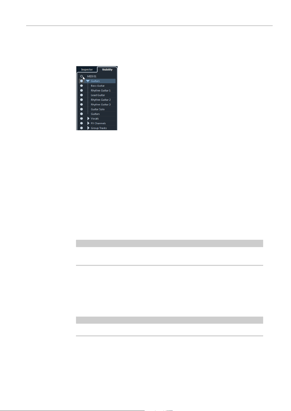
Showing/Hiding Individual Tracks
The Visibility Inspector tab shows a list of all current tracks. Here you can show
and hide individual tracks.
• To show or hide a track in the track list, click a dot to the left of a track.
• To activate or deactivate several
press [Return].
• To show a hidden track exclusively, [Shift]-click the dot.
• To expand or collapse a folder, click the triangle to the left of a folder track.
Number of Visible Tracks
The number of visible tracks is indicated above the track list. This lets you know how
many tracks are hidden.
• Click the number of visible tracks to show all tracks.
Tracks that are hidden through the track types filter cannot be shown by clicking the
number of visible tracks.
Track Visibility Agents
tracks at the same time, select them and
Track visibility agents allow you to show or hide all tracks, selected tracks, or tracks
with certain properties.
If you divide the track list, the top part of the list is not affected by visibility agents.
To open the Track Visibility Agents pop-up menu, perform one of the following
actions:
24
Page 25

Working with the New Features
NOTE
Track Visibility Management
• Click the Track Visibility Agents button on the toolbar.
• Open the Visibility Inspector tab and right-click to open the context menu.
ELATED LINKS
R
Showing Tracks with Specific Properties
Visibility Tab on page 23
• To open the Track Visibility Agents pop-up menu, click the Track Visibility
Agents button in the toolbar.
Show All Tracks
Shows all tracks of your project.
Show
Only Selected Tracks
Shows only the tracks that are selected.
Hide Selected Tracks
Hides all tracks that are selected.
Show Tracks with Data
Shows all tracks with events or parts. The tempo track, the signature track,
e cho
and th
rd track are always shown.
Show Tracks with Data at the Cursor Position
Shows all tracks with events or parts at the cursor position.
Show Tracks with Data between the Locators
Shows all tracks with events or parts between the left
and right locators.
Show Tracks with Selected Events
Shows all tracks with sele
cted eve
nts or parts.
Hide Muted Tracks
Hides all tracks that are muted.
You can assign key commands for the track visibility agents in the Channel & Track
Visibility category of the Key Commands dialog.
25
Page 26

Working with the New Features
PROCEDURE
Track Visibility Management
Undoing Visibility Changes
You can undo/redo up to 10 visibility changes.
1. In the Project window toolbar, click the Track Visibility Agents button.
2. Select Undo Visibility Change.
Advanced Agents
The Advanced Agents submenu features Project Logical Editor presets that allow
you to show or hide tracks with specific properties.
• Click the Track Visibility Agents
Try out the different presets to show or hide your tracks, or use them as a starting
n
t for your own presets in the Project Logical Editor.
poi
bu
tton in the Project window toolbar, and
select Advanced Agents to open a submenu.
Track Visibility Configurations
The Track Visibility Configurations button on the Project window toolbar allows
you to create configurations that are useful for switching quickly between different
visibility setups. Track visibility configurations are saved with the project.
Track Visibility Configurations
This toolbar button displays the name of the
Configurations List
A list of configurations is shown as soon as you create at least one
o
nfiguration. To load a configuration, select it from this list.
c
Create Configuration
active configuration.
Opens the Create Conf
configuration and enter a name for it.
Update Configuration
If you change the active configuration, this is indicated by an asterisk after the
configur
configuration.
ation name. Use this function to save changes to the active
iguration dialog that allows you to save the
26
Page 27

Working with the New Features
PROCEDURE
NOTE
NOTE
Track Visibility Management
Rename Configuration
Delete Configuration
Move Configuration to Position
Synchronizing Track and Channel Visibility
You can synchronize the track visibility in the Project window with the channel
visibility in the MixConsole.
Opens the Rename Configuration dialo
g that allows you to rename the
active configuration.
Allows you to delete the active configuration.
This function becomes available if 2 or more configurations exist. It allows you
to change
the position of the active configuration on the menu. This is useful,
as you can assign key commands to the first 8 configurations in the Channel
& Track Visibility category of the Key Commands dialog.
1. In the Inspector, open the Visibility tab and click the dot to open the Sync
Track/Channel Visibility menu.
2. Select Sync Project and MixConsole to synchronize the track visibility with
the channel visibility.
The dot in the Visibility tab changes to indicate that the track and channel visibility
are synchronized.
You can only synchronize the track visibility in the Project window with the
channel visibility of one MixConsole. If you enable Sync Track/Channel
Visibility for a second MixConsole, the first link is lost.
If you divide the track list, the top part of the list is not affected. Likewise,
channels in the left or right zones of the MixConsole are not synchronized.
27
Page 28

Working with the New Features
PROCEDURE
NOTE
NOTE
Automatic Hitpoint Detection
Finding Tracks
The Find Tracks function allows you to find specific tracks. This is useful if you have
a large project with many tracks or if you have hidden tracks using the track visibility
features.
1. Click Find Tracks above the track list, to open a selector that lists all tracks.
2. In the search field, enter the name of the track.
As you type, the selector updates automatically.
3. In the selector, select the track and press [Return].
The selector closes and the track is selected in the track list.
If the track was outside the view or hidden, it is now shown. Tracks that are
hidden using Filter Track Types are not shown.
Automatic Hitpoint Detection
When you add an audio file to your project by recording or by importing, Nuendo
automatically detects hitpoints. This allows you to navigate to hitpoints of an audio
file from within the Project window.
For long audio files, hitpoint detection may take a wh
based on hitpoints are disabled during the calculation.
• To disable automatic hitpoint detection, select File > Preferences > Editing
> Aud
io, and deactivate Enable Automatic Hitpoint Detection.
ile. All operations that are
In the Project window, hitpoints are shown for the selected event, provided that the
zoom factor is high enough. To hide them, select File > Preferences > Event
Display > Audio and disable Show Hitpoints on Selected Events.
RELATED LINKS
Using Hitpoints to Locate Audio Positions in the Project Window on page 29
28
Page 29

Working with the New Features
PROCEDURE
Automatic Hitpoint Detection
Using Hitpoints to Locate Audio Positions in the Project
Window
You can navigate through the hitpoints of an audio event in the Project window.
P
REREQUISITE
Enable Automatic Hitpoint Detection is activated in the Preferences dialog
(Editing–Audio).
1. Select the audio track that contains the audio event for which you want to
locate hitpoints.
2. Press [Alt]/[Option]-[N] to navigate to the next hitpoint, or [Alt]/[Option]-[B] to
navigate to the previous hitpoint.
The project cursor jumps to the respective hitpoint.
Filtering Hitpoints
You can filter hitpoints in the Hitpoints Inspector tab of the Sample Editor.
You can use the following parameters to filter hitpoints:
Threshold
This filters hitpoints by their peaks. This allows you to discard hitpoints of
quieter crosstalk signals, for example.
Minimum Length
This filters hitpoints by the distance between two hitpoints. This allows you to
avoid creating slices that are
Beats
This allows you to filter hitpoints by their m
discard hitpoints that do not fit within a certain range of a defined beat value.
too short.
usical position. This allows you to
29
Page 30

Working with the New Features
NOTE
Score Editor Improvements (NEK only)
Score Editor Improvements (NEK only)
Score Inspector
The Score Editor Inspector now features two Inspector tabs: Symbols and
Inspector.
clic
To open an Inspector tab,
• The Symbols tab contains score-related functions. For a description of these
functions, refer to the chapter “Working with symbols” in “Part II: Score layout
and printing” of the “Operation Manual”.
k its header.
• The Inspector tab co
functions, refer to the description of the Key Editor Inspector in the chapter
“The MIDI Editors” in the “Operation Manual”.
The Quick Staff Setup section has been moved from the Symbols tab to the
Inspector tab.
Re-Record Mode
The Re-Record mode allows you to reinitiate a recording with a single click.
The first recording is canceled, the events are removed, and recording is restarted
from th
e exact same position.
ntains MIDI-related functions. For a description of these
30
Page 31

Working with the New Features
PROCEDURE
NOTE
Re-Record Mode
Re-Recording
1. Activate Transport > Re-Record.
2. Activate recording as usual.
3. Hit the Record button again to restart recording.
RESULT
The project cursor jumps back to the record start position and recording is
re
initiated. Pre-roll and pre-count settings are taken into account.
The previous recordings are removed from the project and cannot be retrieved
using Undo. However, they remain in the Pool.
Common Record Modes
The Common Record Modes determine what happens if you click the Record
button during an audio or MIDI recording.
• In the Transport pan
open the Common Record Modes pop-up menu.
Punch In/Out
In this mode, the recording is stopped.
Re-Record
In this mode, the recording is removed and recording is
Start Recording at Cursor
In this mode, recording starts from the cursor position.
St
art Recording at Left Locator
e
l, click the upper part of the Record Modes section to
restarted.
In this mode, recording starts from the left locator.
31
Page 32

Working with the New Features
NOTE
ADR
ADR
The ADR panel allows you to perform ADR and language dubbing tasks.
Sometimes, you must re-record dialogue from pro
different language. When you do this, the original takes are played back to allow the
dubbing actor to listen to the original production track as a guide. The actor can
then rehearse the dialogue and re-record it. These tasks can be performed with the
ADR functions that are located in the ADR panel of the Marker window.
To open the ADR panel, select Project > Markers and click ADR a
the Marker window.
To get the most out of the ADR functions, it is important that you understand the
following concepts:
duction tracks or dub them in a
t the bottom of
• ADR and Selecting Markers
• ADR Statuses (Rehearse, Record, Review)
• ADR Modes (Automatic, Free Run)
ADR and Marker Selection
The ADR functionality makes extensive use of markers.
In the marker list, you can select cycle markers to set the start and end position for
Rehea
If you select position markers, only th
If no marker is selected, the start position for any ADR status in Automatic mode is
determined
by the project cursor position.
You can also select multiple markers, for example, to combine multiple takes.
rse, Record, and Review.
by the left locator. In Free Run mode, the start position is determined
e sta
rt position is set.
32
Page 33

Working with the New Features
NOTE
ADR
ADR Statuses
The ADR statuses Rehearse, Record, and Review are transport functions that
have been designed specifically for ADR tasks.
1) Rehearse
2) Record
Allows you to play back the take, so that the artist can rehearse it.
ADR Modes
Allows
3) Review
A
The ADR statuses take into account all
ELATED LINKS
R
ADR Setup on page 36
You can select either Automatic mode or Free Run mode.
The ADR modes take into account all settings in the ADR Setup window.
• Automatic
This mode is activated by default. It allows you
the position and length of the selected marker. In the different ADR statuses,
the following happens:
you to record the take on
llows you to play back the recorded take for review.
the record-enabled track.
settings in
the ADR Setup window.
to record a take according to
If you click Rehearse, a loca
the selected markers is selected in the Project window ruler. The project
cursor jumps to the start of the Pre-roll phase and playback starts. At the end,
the project cursor automatically jumps back to the start position.
If you click Record, the pr
and playback starts. When the left locator is reached, recording starts. At the
end of the Post-roll phase, recording stops automatically and the project
cursor jumps back to the left locator. The recorded event is automatically
resized to this position.
If you click Rev
and playback starts. At the end of the Post-roll phase, playback stops
automatically and the project cursor jumps back to the take start position.
iew, the pro
tor range according to the position and length of
oject cursor jumps to the start of the Pre-roll phase
ject cursor jumps to the start of the Pre-roll phase
33
Page 34

Working with the New Features
NOTE
ADR
• Free Run
Activate this mode for more flexibility. It allows you to use the project cursor
position as the ADR start position. You can set the project cursor position
manually or using a marker in the marker list. Free run mode works as follows:
ADR Panel
If you click Rehearse, th
e left locator is set to the project cursor position and
playback starts from there. If Pre is enabled, playback starts with the pre-roll
that you defined in the ADR Setup window. Playback stops when you click
Stop.
If you click Record, th
e project cursor jumps to the take start position and
recording starts. If Pre is enabled, playback starts at the beginning of the
pre-roll phase and recording starts when the take start position is reached.
Recording stops when you click Stop.
If you click Review, th
e project cursor jumps to the take start position and
playback starts. If Pre is enabled, playback starts at the beginning of the
pre-roll phase. Playback stops when you click Stop.
If Return to Start Position on Stop is activated in the Preferences dialog
(Transport page), the project cursor returns to the take start position.
The ADR panel is located in the lower part of the Marker window.
Select Project > Mark
ers and click ADR at the bottom of the Marker window.
1) Locate Previous/Next Marker in Marker Window
Allows you to select the previous/next marker
in the marker list. If Sync
Selection is activated in the Marker Preferences, the corresponding locator
range is also selected in the Project window ruler.
2) Pre
-Roll On/Off
Allows
you to activate/deactivate a pr
e-roll for the Free run mode.
34
Page 35

Working with the New Features
ADR
3) Free Run Mode On/Off
4) Rehearse
Activate this mode to start from the project cursor position. On stop, the
sor returns to the start position by default. You can change this by
cur
deactivating Return to Start Position on Stop in the Preferences dialog
(Transport page).
Deactivate this mode to use the selected cycle marker. Pre-roll and post-roll
are determi
P
lays back the selected take so that the artist can rehearse it.
ned by the settings on the General tab in the ADR Setup window.
5) Re
cord
Rec
ords the selected take on the record-enabled track.
6) Review
lays back the take for review. To enable this, on the Signal
P
Switchboard,
activate Take in Review mode for Other Audio for the Control Room and
Cue 1.
7) G
uide Track for Cue 1 On/Off
A
llows you to mute the guide track for cue 1.
8) Guide Track for Control Room On/Off
llows you to mute the guide track for the Control Room.
A
9) Setup
d
Allows you to open the ADR Setup win
ow.
10) Marker Preferences
Allows you to show the marker preferences.
11) Show ADR Pa
Allows
you to show/hide the ADR panel.
nel
12) Show Details View
Allows you to show/hide the details view.
ELATED LINKS
R
ADR Modes on page 33
35
Page 36

Working with the New Features
NOTE
ADR
ADR Setup
General Tab
1) Pre-roll/Post-roll
Allows you to enter a pre-roll/post-roll value.
In the Preferences dialog (Record–Audio page) you can set a value for
Audio Pre-Record Seconds. The post record time corresponds to the
post-roll time.
2) ADR Track Assignment
Allows you to specify which tracks you want to use as guide, M&E, and mic
signal.
3) Re
4) Record File Naming
ELATED LINKS
R
cord Enable Target Track
llows you to automatically record-enable the target track. To enable this, you
A
must se
A
the track name
Enabling Automatic Record-Enabling for Target Tracks on page 45
t up the Target Track marker attribute.
Scheme
llows you to specify a naming scheme for the recorded files that is added to
as a suffix.
36
Page 37

Working with the New Features
NOTE
ADR
Video Tab
1) Pre-roll/Post-roll
Allows you to enter a pre-roll/post-roll value.
In the Preferences dialog (Record–Audio page) you can set a value for
Audio Pre-Record Seconds. The post record time corresponds to the
post-roll time.
2) Primary Swipe
Activate this to display a bar that swipes from the left to the right side of the
o Player window as a take start indicator. The pre-roll value defines the
Vide
duration of the swipe.
Activate Swipe to Ce
nter to display two bars that swipe from the left and right
sides to the center of the Video Player window.
3) Counter
Activate this to display a count-in by numbers as a take start indicator in the
Video Player
window. Specify a start number in the value field to the right.
The interval between each count is one second. The metronome is
automatically synchronized with the counter.
Activate Invert
Counter to invert the order of the displayed numbers.
Activate Show
Black during Pre-/Post-roll to show a black picture during
pre-roll and post-roll.
37
Page 38

Working with the New Features
ADR
4) Show Dialogue during ADR/Always show Dialogue
These options allow you to show the dialogue attribute of the selected marker.
Activate Show Dialogue during ADR
to display the Dialogue marker
attribute as a video overlay in the Video Player window during one of the ADR
modes.
Activate Always show Dialo
gue to always display the dialogue marker
attribute.
5) Take Length
A
ctivate this to show a take length indicator at the bottom of the Video Player
win
dow.
Indicator
6) ADR Status Indicator
A
ctivate this to show an ADR status indicator at the top left corner of the
Video Player
Rehearse status is indicated wit
window.
h
a yellow indicator, record status with a red
indicator, and review with a green indicator.
7) Secondary Swipe
h
If you selected multiple markers, activating t
is option displays a swipe as a
pre-roll for every take.
8) Marker Pre-roll
Allows you to define a pre-roll for the secondary swipes.
38
Page 39

Working with the New Features
NOTE
ADR
Signal Switchboard Tab
The Signal Switchboard tab allows you to define which signals are heard during
the different ADR phases. This helps you to set up different schemes for the
dubbing artist and the ADR operator, for example.
1) Control Room section
Allows you to specify the track that you hear in the Control Room channel
during Rehearse, Record, and Review. F
urthermore, you can determine if
you want to hear the signal during the preroll, take, and postroll phases.
2) Cue selectors
Allow you to switch to another cue channel.
3) Cue section
Allows you to specify the track that you hear in the selected Cue channel
ring re
du
hearse, record, and review. Furthermore, you can determine if you
hear the signal during the preroll, take, and postroll phases.
In the MixConsole, make sure that the Control Room and cue channels are set up
correctly.
39
Page 40

Working with the New Features
PROCEDURE
PROCEDURE
PROCEDURE
ADR
Setting Up ADR Tracks
To use the available functions in the ADR panel, you must set up your project first.
Creating Guide Tracks
The guide track is to play back the original dialogue that you want to replace.
1. Create an audio track or a group and name it so that you can recognize it as
the guide track.
2. Set the Output Routing pop-up menu to the stereo out output bus that is set
as the Main Mix.
Creating M & E (Music and Effects) Tracks
The M&E track is designed to play back music and effects.
1. Create an audio track or group and name it so that you can recognize it as the
M&E track.
2. Set the Output Routing pop-up menu to the stereo out output bus that is set
as the Main Mix.
Creating Mic Tracks
The mic track is designed to lead the signal that is to be recorded. For this to work,
you must activate its Monitor button.
1. Create an audio track for the mic signal.
2. In the Inspector, set the Input Routing pop-up menu to your microphone
input bus.
3. Set the Output Rou
Main Mix.
ing pop-up menu to the output bus that is set as the
t
40
Page 41

Working with the New Features
NOTE
PROCEDURE
PROCEDURE
ADR
4. Activate Monitor for the mic signal track.
Creating Other Tracks
The other tracks are designed for recording and for playback of your recordings.
1. Create as many other audio tracks as you need.
2. In the Inspector of each track, set the Input Routing pop-up menu to your
If you use a mic signal track, set the Auto Monitoring mode in the
Preferences dialog (VST page) to Manual. Otherwise, select Tapemachine
Style.
microphone bus.
3. Set the Output Rou
Main Mix.
t
Creating Cue Channels
Cue channels are used for sending cue mixes, also known as headphone mixes, to
performers in the studio during recording.
1. Select Devices > VST Connections > Studio.
2. Activate Enable/Disable Control Room.
3. Click Add Channel and add at least one cue channel.
ing pop-up menu to the output bus that is set as the
41
Page 42

Working with the New Features
PROCEDURE
NOTE
PROCEDURE
ADR
Setting Up the ADR Environment
Setting up your ADR environment includes importing files and defining takes,
assigning ADR tracks, setting up the routing, configuring video overlays, and
enabling automatic record for target tracks.
Importing Files and Defining Takes
Import your files and define the takes that you want to record by creating cycle
markers.
1. Select File > Import > Video File and navigate to the video file that you want
to import.
2. Select the guide track, select File > Import > Audio File and import the
audio file for the dialogue that you want to replace.
3. Select the M&E track, select File
and effect sounds.
4. Play back the guide track and set up cycle markers for all dialogue that you
want
to re-record.
If you have a take list from a dedicated ADR taker application or an Excel
sheet, you can also import this.
Assigning ADR Tracks
You must define which of your tracks or groups correspond to a specific ADR track.
This is useful for setting up the signal switchboard. The track assignment is stored
with the project.
1. Select Project > Markers.
The Marker window opens.
> Imp
ort > Audio File and import the music
2. Activate Show ADR Panel.
3. Click Setup.
The ADR Setup window opens.
4. Click General.
5. In the ADR Trac
pop-up menus to select the tracks that you want to use as guide, M&E, and
mic signal tracks.
k Assignment section, use the Guide, M&E, and Mic Signal
42
Page 43

Working with the New Features
PROCEDURE
NOTE
PROCEDURE
NOTE
ADR
Setting Up the Routing for Individual Mixes
You can define which signals are heard during the different ADR phases and set up
different schemes for the dubbing artist and the ADR operator, for example. The
routing that you set up is automatically applied when you use the ADR modes. The
settings are saved globally.
1. On the ADR panel, click Setup.
2. In the ADR Setup window, click Signal Switchboard.
3. Activate the checkboxes for the signals that you want to hear on each ADR
The signal switchboard shows all ADR tracks (sources) for the Control Room
(destination) in the upper section and the cues 1 to 4 (destinations) in the lower
section.
track.
To hear the source signal of a specific ADR track during pre-roll, activate the Pre
option for that track. To hear the signal during the take, activate Take. To hear the
signal during post-roll, activate Post.
In the MixConsole, make sure that the Control Room and cue channels are
set up correctly.
RELATED LINKS
Signal Switchboard Tab on page 39
Configuring Video Overlays
You can set up different video overlays that may be helpful for the dubbing artist.
1. On the ADR panel, click Setup.
2. Select the General tab and enter values for Pre-roll and Post-roll.
You might also want to set a value for Audio Pre-Record Seconds in the
Preferences dialog (Record–Audio page). The post record time
corresponds to the post-roll time.
3. Select the Video tab.
43
Page 44

Working with the New Features
NOTE
PROCEDURE
NOTE
ADR
4. In the Video Overlays section, configure which overlays are displayed in the
RELATED LINKS
Enabling Dialogue Display in the Video Player
You can display the dialogue that must be replaced or dubbed in the Video Player
window or on a dedicated video output device.
Video Player window.
To enable the timecode display as an overlay in the Video Player window,
select Devices > Device Setup > Video Player. In the Video Playback
section, activate Show Timecode. To adjust the display position, use the
Position pop-up menu.
General Tab on page 36
REREQUISITE
P
The Dialogue attribute is assigned manually or has been imported via a CSV file.
1. In the Marker window, click Set up Attribute Columns, and activate ADR >
Dialogue.
The Dialogue column is displayed in the Marker window.
2. On the ADR panel, click Setup.
3. In the ADR Setup wind
ow, click Video.
4. In the Video Overlays section, activate Show Dialogue during ADR.
RESULT
The dialogue of the selected marker is shown in the Video Pl
ayer window during
Rehearse, Record, and Review.
You can activate Always Show Dialogue if you want to see the dialogue always,
not only during ADR.
44
Page 45

Working with the New Features
PROCEDURE
NOTE
PROCEDURE
ADR
Enabling Automatic Record-Enabling for Target Tracks
You can automatically record-enable a track when clicking Rehearse, Record, or
Review.
1. In the Marker window, click Set up Attribute Columns, and activate General
2. On the ADR panel, click Setup.
> Target Track.
The Target Track column is displayed in the Marker window.
3. In the ADR Setup wind
4. In the Recording section, activate Record-Enable Target Track.
RESULT
You can now use the Target
number of the track. If you have imported this attribute with the take list, it is shown
automatically.
Only numbers are allowed as values for the target track attribute.
Rehearsing Takes
PREREQUISITE
You have defined takes by creating cycle markers, and set up the signal
Switchboard as required.
ow, click General.
Track column of the Marker window to type in the
1. In the markers list, select the marker for the take that you want to record.
2. On the ADR panel, click Rehearse.
45
Page 46

Working with the New Features
PROCEDURE
NOTE
PROCEDURE
ADR
Switching from Rehearse to Record
You can switch from Rehearse to Record without stopping playback. This is useful,
if you realize during rehearsing that you want to record straight away.
REREQUISITE
P
You are rehearsing a take.
1. On the ADR panel, click Record.
Recording Takes
• If you click Record during the pre-roll phase, playback continues and recording
starts only at the take start position.
• If you click Record during th
position.
e take phase, recording starts directly at the cursor
PREREQUISITE
The dubbing artist has rehearsed the take and is ready to record. You have
record-enabled the track on which you want to record.
You can combine track selection and record-enabling. Selecting File >
Preferences > Editing > Project & MixConsole and activate Enable Record on
Selected Audio Track.
• On the ADR panel, click Record.
The take is recorded.
46
Page 47

Working with the New Features
PROCEDURE
NOTE
NOTE
Control Room
Reviewing Takes
• On the ADR panel, click Review.
AFTER COMPLETING THIS TASK:
If you are satisfied with the recording, proceed with the next take.
You can select the next marker in the marker list by clicking Locate Next Marker in
Marker Window. If Sync Selection is activated in the Marker Preferences, the
corresponding take is also selected in the Project window. Make sure that Track
Selection Follows Event Selection is deactivated in the Preferences dialog
(Editing page).
The take is played back so that the director and the artist can review it.
If you cannot hear the recorded take, open the Signal Switchboard and make
sure that Take is activated in Review mode for Other Audio for the Control
Room and Cue 1.
Control Room
The Control Room features allow you to divide the studio environment into the
performing area (studio) and the engineer/producer area (control room).
To open the Control Room mixer you have 2 options:
•Select Device
This opens the Control Room in a
•Select Devices > Mi
Room/Meter.
This opens the Control Room sec
The Control Room mixer itself is divided into
the tabs at the bottom.
• The Mixer tab
mixing, and mastering, for example.
• The Setup
project.
s > Contro
contains all controls that you use regularly during recording,
ta
b contains settings that you most probably use only once for a
l Room Mixer.
separate window.
xConsole > Set up Window Layout > Control
tion in the MixConsole.
2 sections that you open by clicking
47
Page 48

Working with the New Features
PROCEDURE
NOTE
Control Room
Adding Channels to the Control Room
To be able to use the Control Room, you need to add the channels that you need
first.
1. Select Devices > VST Connections.
2. Click Studio.
3. Click Add Channel.
A pop-up menu lists all available channel types and shows how many instances of
each type are available.
4. Select a channel type.
For most channel types, a dialog opens, that allows you to choose the channel
configuration.
5. Click the Audio Device column to set an audio device for the channel type.
6. Click the Device Port c
RESULT
The Control Room functions are available for use. If you disable the Control Room,
the c
Room.
Output Routing
The channel width of the Control Room can only be as wide as the Main Mix bus.
All other outputs are not routed through the Contro
However, they can be added as additional monitor sources in the VST Connections
wind
shown on the Studio tab. The reason is that the Main Mix is always available as a
monitor source in the Control Room Mixer.
olumn to assign a port for the channel.
You cannot assign the same device port to a bus or channel and a Control
Room channel at the same time.
onfiguration is saved and will be restored when you reenable the Control
l Room Mixer.
ow. When the Control Room is enabled, the Main Mix bus is automatically
48
Page 49

Working with the New Features
NOTE
NOTE
Control Room
Exclusive Assignment of Monitor Channels
Generally, the port assignment to the Control Room channels is exclusive. However,
it can be useful to create monitor channels that share device ports with each other
as well as inputs and outputs. This can be helpful if you use the same speakers as
a stereo pair and also as the left and right channels of a surround speaker
configuration, for example. Switching between monitors that share device ports is
seamless, multi-channel audio is mixed down to stereo as needed. Only one monitor
set can be active at a time.
If your scenario does not require you to assign ports to several monitor channels, it
commended to activate the Exclusive Device Ports for Monitor Channels
is re
option in the Preferences dialog (VST–Control Room page). This way, you can
make sure that you do not accidentally assign ports to inputs/outputs and monitor
channels at the same time.
The state of the Exclusive Device Ports for Monitor Channels preference is saved
together with the Control Room presets. Therefore, if you recall a preset, your
current setting in the Preferences dialog might be overwritten.
Control Room Channels
Each Control Room channel type that you create defines an input or output of the
Control Room Mixer.
Monitor Channels
A monitor channel represents a set of outputs that are connected to monitor
speakers in the Control Room.
You can create up to 4 monitor channels for a mono, stereo, or surround speaker
co
nfiguration. Each monitor can have its own custom downmix settings, input gain,
and input phase settings.
Monitor channels can share hardware inputs or outputs with another bus or
channel. When you create the connections for the monitor channels, device ports
that are already used for other busses or channels are shown in red on the Device
Port pop-up menu. If you select a used port, its previous connection is lost.
49
Page 50

Working with the New Features
NOTE
EXAMPLE
Control Room
Monitor Sources
You can set up different monitor sources and use the Control Room Mixer to
select the mix sources that you want to listen to. Different monitor sources for
dialogue, sound effects, and music are useful in post production setups that require
more than one mix bus.
You can create up to 8 monitor sources for a mono, stereo or surround speaker
co
nfiguration. These can be input or output busses that you set up in the
Inputs/Outputs tab of the VST Connections window, or a group channel.
If you select a monitor source with a wider configuration than the Main Mix bus,
automatic downmixing occurs.
Phones Channel
You can use the phones channel in the Control Room to listen to cue mixes.
You can create 1 phones channel for a stereo configuration. It allows you to listen
main mix or cue mixes or to external inputs on a pair of headphones. You can
to the
also use it for previewing.
Cue Channels
You can use cue channels for sending cue mixes, also known as headphone mixes,
to performers in the studio during recording.
You can create up to 4 cue channels in mono or stereo for 4 discrete cue mixes.
ch
Cue
mix, external inputs, or a dedicated cue mix.
If you have 2 available headphone amplifiers for performers, you can create 1 cue
channel for each cue mix and name them according to their function: vocalist mix,
bass player mix, etc.
annels have talkback and click functions. They allow you to monitor the main
Cue Channels and Cue Sends
For every cue channel that you define in the VST Connections window, each
channel in the MixConsole has a cue send with level, pan, and pre/post-fader
selection. These cue sends can be used to create discrete cue mixes that
performers can listen to.
• In the MixConsole, activa
te Racks
50
> Cue Sends to show the cue sends.
Page 51

Working with the New Features
NOTE
NOTE
NOTE
Control Room
External Inputs
You can use external inputs for monitoring external devices, such as CD players,
multi-channel recorders, or any other audio source.
You can create up to 6 external inputs for a mono, stereo, or surround speaker
onfigur
c
If you select external inputs as input source of an audio channel, you can record
them. In this case, you do not need to assign the device ports to the input channel.
Talkback Channels
You can use talkback channels for communication between the Control Room and
performers in the studio.
ation.
You can create up to 4 talkback channels and assign a mono input channel to each
ne of
o
You can also use talkback channels as input source for audio tracks and record
the
You can insert effects like a compressor or limiter on
ensures that erratic levels do not disturb performers and that clear communication
with everyone is possible.
In the Preferences dialog (VST–Control Room page) the Auto Disable Talkback
Mode allows you to specify how talkback works during playback and recording.
them.
m.
You can route them to each cue channel and use different levels.
Metering Channel
You can use a metering channel for connecting a hardware metering device.
The metering channel allows you to meter monitoring sources without having the
listening vo
feeds the same signal that goes through the meter channel.
lume affect the meter. This channel is a physical ASIO output which
talkback channels. This
The metering channel does not appear in the project.
51
Page 52

Working with the New Features
Control Room
Control Room Mixer
The Control Room Mixer displays information and controls for the channels that
you define on the Studio tab in the VST Connections window.
The Contro
l Room Mixer
is divided into a number of sections that you open by
clicking their header. To open several sections simultaneously, use
[Ctrl]/[Command]-click.
52
Page 53

Working with the New Features
Control Room
External
The External section is only shown if you have added more than one external input
in the VST Connections window.
To switch to another external input, click the input name and select a new external
input from the pop-up menu.
Monitor Sources
The Monitor Sources section allows you to select which monitor sources are
routed to the Control Room.
1) Multiple Monitor Sources
Allows you to listen to several submixes at
must activate the monitor sources that you want to include.
2) Moni
tor Sources
A
llows you to listen to a monitor source. If you want to listen to only one
sour
ce, deactivate Multiple Monitor Sources. If you [Alt]/[Option]-click a
monitor source, you can listen to it exclusively, even if Multiple Monitor
Sources is activated. If you [Shift]-click a monitor source, you can activate
several monitor sources, even if Multiple Monitor Sources is deactivated.
the same time. For this to work, you
53
Page 54

Working with the New Features
Control Room
Cue Channel
1) Activate Cue Channel
2) Source Selectors
Allows you to activate/deactivate the cue channel.
llow you to select the source for the cue channel: monitor mix (Mix), external
A
(Ext), or the cue sends (Cues). The signal presence indicators in the
inputs
upper left corner light up when the source channel is sending data to the cue
channel.
3) Enable Talkback to Cue Channel
Allows you to activate talkback for communication between the Control Room
and the perform
ers in the studio. You can set the level of the talkback signal
with the slider.
4) Activate Metronome Click
A
ctivates the metronome click. Use the Click Level an
d Click Pan controls to
set the volume and the pan position of the metronome click.
5) Signal Level
Allows you to set the signal level.
54
Page 55

Working with the New Features
Control Room
Channels
The Channels section shows the speaker arrangement of the Main Mix bus.
You can use the solo functions to listen to individual ch
can also use this to test your multi-channel speaker system and make sure that the
correct channels are routed to the speakers.
1) Solo Left and Right Channels
Allows you to solo the left and right channels.
2) Solo Front Channels
Allows
3) Solo Surround
you to solo the front channels.
Channels
annels of the Main Mix. You
4) Listen to Solo Channe
5) Listen to Surround Channels on Front
6) Solo LFE
Monitors
The Monitors section allows you to select and configure the monitor sets.
Allows you to solo the surround channels.
ls
on Center Channel
Allows you to listen to all soloed speakers in the center channel. If the center
chan
nel is not available, the channels are distributed equally to the left and
right.
Channels
Allows you to solo the surround channels and route them to the front
speakers.
Channel
Allows
you to solo the LFE channel.
55
Page 56

Working with the New Features
Control Room
Downmix Presets
The Downmix Presets section allows you to configure downmix presets.
1) Assign Downmix Preset
Allows you to configure a downmix preset for
the Monitors section.
2) Select Output Confi
Allows you to select an output channel configuration.
Phones Channel
1) Activate Phones Channel
Allows you to activate/deactivate the phones channel.
the monitor that is selected in
guration
2) Source Selectors
llow you to select the source for the phones channel: monitor mix (Mix),
A
ternal inputs (Ext), or the cue sends (Cues). The signal presence indicators
ex
in the upper left corner light up when the source channel is sending data to
the Phones channel.
3) Signal Level
Allows you to set the signal level. [Ctrl]/[Command]-click to set the level to the
ference level specified in the Preferences dialog (VST–Control Room
re
page).
4) Activate Metronome Click
Act
ivates the metronome click.
56
Page 57

Working with the New Features
Control Room
5) Click Level and Click Pan
Use the Click Level and Click Pan con
position of the metronome click.
6) Enable Listen for
Enables
the listen bus function.
Output
7) Listen Level
Allows you
to set the listen level.
Control Room Channel
The Control Room channel is the representation of the bus that is set up as the Main
Mix bus on the Outputs tab in the VST Connections window or the one that is
selected as monitor source.
trols to set the volume and the pan
The following section contains a description of the individual controls.
1) Activate Control Room Channel
Allows you to activate/deactivate th
e Control Room channel.
2) Signal Level
Allows you to set the volume for the Control Room output. This does not affect
recording input level
the
or the Main Mix level for exporting mixdowns.
[Ctrl]/[Command]-click to set the level to the reference level specified in the
Preferences dialog (VST–Control Room page).
57
Page 58

Working with the New Features
Control Room
3) Signal Meter
Shows the volume for the
Control Room output.
1) Source Selectors
Allow you to select the source for the Control Room channel. The available
sour
ces depend on the channels that you added to the Control Room. The
signal presence indicators in the upper left corner light up when the source
channel is sending data to the Control Room channel.
2) Dim Sign
al
Activate this to lower the Control Room level by a fixed amount. This allows
quick reduction in monitor volume without disturbing the current monitor level.
Clicking the DIM button again returns the monitor level to the previous setting.
3) Use Reference
Ena
ble this button to set the Control Room
Level
level to the reference level
specified in the Preferences dialog (VST–Control Room page). The
reference level is the level that is used in calibrated mixing environments, such
as film dubbing stages.
a
4) Activate Metronome Click
Act
ivates the metronome click.
1) Monitor Selectors
Allow you to select another monitor source.
2) Downmix Pres
et Selectors
Allow you to select another downmix preset.
3) Activate Talkback
llows you to activate talkback for communication between the Control Room
A
and the perform
ers in the studio. Click to activate, click and hold for
momentary mode.
58
Page 59

Working with the New Features
Control Room
4) Talk Off
1) Click Level and Click Pan
If you add more than 1 talkback channel, Talk Off becomes available. This
you to deactivate all activated talkback channels.
allows
Use the Click Level and Click Pan con
trols to set the volume and the pan
position of the metronome click for the Control Room channel.
2) AFL/PFL
A
llows you to determine whether the signal of a listen-enabled channel is
routed to the Con
trol Room channel after applying the fader and pan settings
(AFL) or before applying the fader and pan settings (PFL).
3) Enable Listen for Output
Enables the
4) Li
A
sten Level
llows you to adjust the volume of listen bus signals that are routed to the
listen bus function for the Control Room output.
Control Room output.
5) Li
sten Dim
Allows
you to adjust the volume of the
Main Mix (or monitor source) when
channels are in listen mode. This keeps listen-enabled channels in context
with the Main Mix. If the Listen DIM level is set to the minimum value, you only
hear the listen-enabled channels.
6) Talk Dim
When Talkback is active,
channels in the Control Room Mixer is reduced, to prevent unwanted
feedback.
Control Room Setup
The Control Room setup contains additional settings for the channels.
• To open the Control Room setup, clic
the Control Room.
this slider controls how much the output of all the
k the Setup tab at the bottom right of
59
Page 60

Working with the New Features
Control Room
The Control Room setup is divided into a number of sections that you open by
clicking their headers.
Input Gain
Setting up the input gain can be useful in the following situations:
• To balance the level of exte
rnal inputs, that is CD players and other sources
to the Main Mix level, for A/B comparisons.
60
Page 61

Working with the New Features
Control Room
• To balance the level of your monitor systems, so that switching between sets
Input Phase
of speakers does not change the playback volume.
Reversing the input phase can be useful for external inputs and monitor speaker
outputs.
Insert Effects
Each Control Room channel has a set of insert effect slots.
• Use the inserts on the Control Room channel for metering and spectral
analysis plug-ins
All solos including the Listen bus will come through the Control Room channel
and allow analysis of
of the Control Room channel can prevent accidental overloads and damage
to speaker systems.
• Use the inserts for the talkback channel to
talkback microphone.
.
individual sounds. A brickwall limiter in the last insert slot
control the dynamics of the
This will help protect performers’ hearing and ensure that everyone can be
ar
d over the talkback microphone.
he
• Use the monitor inserts for surround decoding or brickwall limiting to protect
nsit
ive monitor speakers.
se
Each monitor channel has a set of eight inserts, all of which are po
Room fader.
61
st Control
Page 62

Working with the New Features
PROCEDURE
Control Room
Setting Up a Cue Mix
You can create a cue mix from the fader and pan levels that are used in the
MixConsole and change them to meet the needs of the individual performers.
1. In the MixConsole, select the channels from which you want to copy the
settings.
2. In the Control Room, right-click on a cue channel to open the context menu.
This applies the function only to this cue channel.
• If you want to apply the function all cue channels, click anywhere but on a cue
channel to open th
3. Select From selected mixer channels and select one of the functions.
e context menu.
Cue Mix Context Menu
Change Cue Sends Levels
Allows you to adjust multiple send levels at the
Use Current Mix Levels
Allows you to copy the fader levels of t
This sets all cue send levels for the selected tracks to the level of the main
channel fader. It also changes the cue send status to pre-fader, so that
changes in the main mix do not affect the cue sends.
Use Current Pan Settings
Allows you to copy pan information from the main mix to the cue sends of the
selected tracks. If th
output of the cue send is the sum of the left and right channels.
Enable Cue Sends
Allows you to activate the cue sends of the selected channels. To be able to
ar the cue mix for a cue channel, the cue sends must be enabled.
he
Disable Cue Sends
Allows you to disable the cue sends of the selected channels.
e cue send is mono, the pan setting is copied, but the
same time.
h
e selected tracks to the cue sends.
62
Page 63

Working with the New Features
PROCEDURE
Loudness
Reset Cue Sends
Allows you to deactivate the cue sends, to change the send level of all
selected ch
any chan
individual cue channels, raise the level on that channel.
annels to 0 dB and to set the signal source to post-fader. This way,
ges to the main mix also change the cue mix. To raise the level of
Adjusting the Overall Cue Send Level
You can adjust multiple send levels at the same time for the cue send mix, keeping
the blend intact while lowering the overall volume. This is sometimes necessary,
because the levels in the main mix are often optimized for the loudest possible signal
level without clipping. This means that when you create a “more me” mix, you may
find that there is not enough headroom available in the cue send to raise levels
without introducing clipping.
1. In the MixConsole, select the channels that you want to modify.
Loudness
2. In the Control Room, right-click a cue channel to open the context menu.
3. Select From selected mixer channels >
4. Activate Rela
This way, you adjust the existing levels. By deactivating Relative Mode, all cue sends
are set to the same absolute level.
5. Adjust the level as necessary.
The level of all selected cue sends is adjusted by the set amount.
6. Click OK.
Nuendo allows you to measure the loudness in compliance with the loudness
recommendation R 128 of the European Broadcasting Union (EBU).
Measurements that correspond to this recommendation consider loudness,
loudness range, and maximum true peak level values.
tive Mode.
Change Cue Sends Levels.
Loudness Measurement
The following measurements are performed:
• Integrated Loudness
verage loudness that is measured over the whole track in LUFS (Loudness
A
Unit, re
According to the loudness recommendation R 128, audio should be
normaliz
ferenced to Full Scale).
ed at -23 LUFS (±1 LU).
63
Page 64

Working with the New Features
Loudness
• Short-Term Loudness
• Momentary Loudness
Loudness Range
This measures the dynamic range over the whole title in LU (Loudness Units). It
reports the ratio between the loudest and the quietest non-silent sections. The
audio is divided into small blocks. Every second there is one audio block, and each
block lasts 3 seconds so that the analyzed blocks overlap.
The top 10 % of the quiet blocks and the top 5 % of the loud blocks are excluded
from
loudest and quietest remaining audio blocks. This measurement helps you to decide
if and how much compression or expansion you can or should apply to the audio.
Loudness that is measured every second on an audio block of 3 seconds. This
gives information about
the loudest audio passages.
Maximum value of all momentary loudness values that are measured every
100 ms in an audio range of 400 ms.
the final analysis. The calculated loudness range is the ratio between the
True Peaks
When a digital signal is converted to an analog signal, EBU R 128 recommends that
you rather measure an estimation of the real peaks instead of relying on digital
peaks. This avoids clipping and distortion.
Naming and Units
The EBU R 128 proposes the following naming and units conventions:
• A relative measurement, such as a value that is relative to a reference level:
LU as
• An absolute measurement, LUFS as Loudness Unit referenced to Full Scale.
1 LUFS can be un
Loudness Unit (1 LU is 1 dB).
derstood as 1 dB in the AES-17 scaling.
64
Page 65

Working with the New Features
NAVIGATION PATH
Loudness
Loudness Meter
The loudness meter allows you to analyze, measure, and monitor the loudness of
your project in real-time during playback or mixing.
Devices > Control Room Mixer > Meter > Loudness > Configure Loudness
Settings
• The green triangle on the left side shows the integrated loudness value.
• The gray triangle on the right side shows the short-term loudness.
65
Page 66

Working with the New Features
Loudness
The following parameters are available:
1) Measure Loudness
Allows you to activate the loudness measurement.
2) Switch between LU
A
llows you to switch the meter scale between LU (relative values) and LUFS
(absolut
e values).
3) Configure Loudness Setti
and LUFS
ngs
Opens a dialog with further loudness settings.
4) Re
set Loudness
A
llows you to reset the loudness measurement.
5) Momentary Max.
Shows the maximum of all measured momentary loudness values.
6) Short-Term
Shows the loudness that is measured over a duration of 3 s.
7) Integr
ated
Sh
ows the average loudness that is measured from start to stop. The period
measurement is shown in the Time display. The recommended value for the
of
integrated loudness is -23 LUFS. This absolute value is the r
the relative LU scale where -23 LUFS equals 0 LU.
eference point for
8) Ra
nge
Sh
ows the dynamic range of the audio that is
measured from start to stop.
This value helps you to decide how much dynamic compression you can
apply. The range that is recommended for highly dynamic audio, like film
music, for example, is 20 LU.
66
Page 67

Working with the New Features
NAVIGATION PATH
Loudness
9) True Peak
Shows the true peak level of the audio. The maximum permit
in production is -1 dB.
10) Time
Shows the duration of integrated loudness measurement.
Loudness Settings
Devices > Control Room Mixer > Meter > Loudness > Configure Loudness
Settings
ted true peak level
The following parameters are available:
1) Select Preset
Allows you to create, load, and remove loudness presets.
2) Momentary Max.
Allows you to specify a reference value and a tolerance value for the maximum
nt
mome
ary loudness. If higher values are detected, the clipping indicator in
the loudness meter turns red.
3) Short-Term
Allows you to specify a reference value and a tolerance value for the
t-term loudness. If higher values are detected, the clipping indicator in the
r
sho
loudness meter turns red.
4) Integr
ated
A
llows you to specify a reference value and a tolerance value for the
grated loudness. If higher values are detected, the clipping indicator in the
inte
loudness meter turns red.
67
Page 68

Working with the New Features
NAVIGATION PATH
Loudness
5) True Peak
Allows you to specify a reference value and a tolerance value for the true peak
level. If hi
gher values are detected, the clipping indicator in the loudness
meter turns red.
6) Switch between LUFS
7) Switch between EBU
8) Reset on Start
Loudness Track
The loudness track allows you to record the loudness of your whole project or of
specific sections.
Project > Add Track > Loudness
and LU
Allows
(relative values)
you to switch the meter scale between LUFS (absolute values) and LU
.
+9 Scale
and EBU +18 Scale
Allows you to switch the meter scale between EBU +9 and
ctivate this to reset all values on playback start.
A
EBU +18.
1) Loudness curve
Shows the loudness values that were detected during the loudness
urement.
meas
2) Re
ference loudness level
Sh
ows the EBU R-128 reference loudness level of -23 LUFS (0 LU).
3) True peaks
eed th
Shows the detected true peaks that exc
e reference value that you can
set up in the Loudness Settings dialog.
68
Page 69

Working with the New Features
Loudness
Loudness Track Controls
1) Activate Loudness Calculation
2) Enabl
Allows you to activate the loudness calculation.
e
Recording of Loudness Curve
Allows you to record the loudness curve on the loudness track.
3) Switch Between LU and
LUFS
Allows you to switch the meter scale between LU (relative values) and LUFS
(absolut
4) Visibl
Allows
e values).
e Loudness - upper/lower limit
you to adjust the visible loudness. Click the values for the
lower limit, and drag the slider up or down.
5) Quick loudness analysis
Allows you to perform a quick loudness analysis of
the section that is
encompassed by the left and right locators.
6) Jump
to previous/next True
Allows you to jump to the previous/next
7) Clear Loudness Curv
e
Peak
true peak in the loudness curve.
Allows you to clear the loudness curve.
upper or
69
Page 70

Working with the New Features
PROCEDURE
Loudness
Loudness Track Inspector
The loudness track inspector shows the most important values of the loudness
meter.
1) Short Term
Shows the loudness that is measured over a duration of 3 s.
2) Integr
3) Ra
4) True Peak
ated
Sh
ows the average loudness that is measured from start to stop. The period
of
measurement is shown in the Time display. The recommended value for the
integrated loudness is -23 LUFS. This absolute value is the r
the relative LU scale where -23 LUFS equals 0 LU.
nge
Shows
helps you to decide how much dynamic compression you can apply. The
range that is recommended for highly dynamic audio like film music is 20 LU.
Shows the true peak level of the audio. The maximum permi
in production is -1 dB.
the dynamic range of the audio measured
from start to stop. This value
eference point for
ted true peak level
t
Measuring Short-Term Loudness during Playback
You can record and display the short-term loudness during playback as a curve on
the loudness track.
REREQUISITE
P
You have added the loudness track to your project.
1. In the track list for the loudness track, activate Activate Loudness
Calculation.
By default, loudness calculation is deactivated for performance reasons.
70
Page 71

Working with the New Features
PROCEDURE
Loudness
2. Activate Enable Recording of Loudness Curve.
3. Play back your project.
RESULT
The short-term loudness level is measured in real-time at the cursor position. The
rresponding loudness curve is written to the loudness track.
co
Measuring Short-Term Loudness Off-Line
You can record and display the short-term loudness for a defined section only on
the loudness track using off-line analysis.
REREQUISITE
P
You have added the loudness track to your project.
1. Set up the left and right locators to encompass the section that you want to
analyze.
2. In the track list for the loudness track, activate Activate Loudness
Calculation.
By default, loudness calculation is deactivated for performance reasons.
3. Click Quick Analysis.
RESULT
The loudness curve is created for the defined section and displayed on the
loudne
ss track.
Normalizing Loudness on Export
You can normalize your audio to the integrated loudness on export. However, this
is only suited for small level deviations and does not compensate for proper mixing.
71
Page 72

Working with the New Features
Loudness
• Normalize to Integrated Loudness
Activate this to normalize your audio to the integrated loudness value
ified in the field to the right.
spec
• Max. Tr
ue Peak
Level
Activate this to limit the peak levels to the value specified in the field to the
right
.
72
Page 73

About the New Plug-Ins
The new plug-ins are listed below.
Bass Manager
This plug-in allows you to achieve full-range sound even if your speakers or
your LF
REVelation
This plug-in produces a high-quality algorithmic reverb with early reflections
and reverb tail.
E are small.
New Plug-Ins
Magneto II
his distortion plug-in simulates the sa
T
on analog tape machines.
LoopMash FX
This plug-in is a live performance effect of
controlled by a MIDI keyboard.
Gate Improvements
This plug-in now features an additional Range par
amount of attenuation when the gate is closed. This new parameter is also
available in the Channel Strip module of the MixConsole.
HALion Sonic SE 2
This synth is the successor to HALion Sonic SE with a revised graphical user
rface and the new analogue synth module Trip.
inte
Groove Agent SE 4 (NEK only)
This drum sampler is the successor to Groove Agent ONE with enhanced
functionality. Its
your beats.
VST Connect SE 2
familiar MPC-style layout with 128 pads allows you to create
turation and compression of recordings
fering DJ effects that can be
ameter which defines the
This plug-in is the successor to VST Connect SE. It allows you to collaborate
other musicians around the globe and communicate peer-to-peer.
with
Record your performances with sample-accurate sync and use the video
feed, talkback, and chat functions.
73
Page 74

New Plug-Ins
NOTE
About the New Plug-Ins
For detailed information, refer to the following separate documents: “Plug-in
Reference”, “HALion Sonic SE”, “Groove Agent SE”, “VST Connect SE”.
74
Page 75

Steinberg Hub
PROCEDURE
When you start Nuendo, when you open projects, or when you create new projects
using the File menu, Steinberg Hub opens. Steinberg Hub keeps you up to date
with the latest information and assists you with organizing your projects.
Further Improvements
• If you do not want to make use of the fu
> Preferences > General and deactivate Use Steinberg Hub.
• To open the last project on startup, select File > Pr
activate Open last Project on Start Up.
nctions of Steinberg Hub, select File
efer
ences > General and
Drum Maps and VST3 Instruments (NEK only)
If you select a VST3 instrument such as Groove Agent SE 4 as an output for a MIDI
or instrument track, you can create a new drum map that contains the pitch and
name data that is provided by the instrument.
Creating a Drum Map for Groove Agent SE
You can create a drum map for MIDI or instrument tracks that are routed to Groove
Agent SE.
REREQUISITE
P
You have created a MIDI or instrument track and loaded Groove Agent SE.
1. In the Inspector for the track, open the Drum Maps pop-up menu, and select
Create Drum Map From Instrument.
2. In the Drum Maps pop-up menu, select Drum Map Setup.
75
Page 76

Further Improvements
NOTE
PROCEDURE
NOTE
Track Quick Control Presets
3. In the Drum Maps list of the Drum Map Setup dialog, select Groove Agent
SE.
The sounds and settings of the Groove Agent SE drum map are displayed to the right.
The instruments and pitches correspond exactly those shown in Groove Agent SE.
If you select a MIDI part and select MIDI > Open Drum Editor, the drum
sound list shows exactly the same settings.
Track Quick Control Presets
For audio, instrument, MIDI, FX, and group tracks, you can now save and load your
own Quick Control assignments as presets or use the factory presets.
Saving/Loading Track Quick Control Assignments as Presets
1. In the Inspector for your track, open the Quick Controls section.
For instrument tracks, the track quick controls are set to the 8 default VST quick
controls of the loaded instrument by default.
2. Click Preset Management in the top right corner of the Inspector section
and select one of the presets.
The Track Quick Control assignment changes and gives you access to the channel
parameters.
You can also make your own assignments and save them as presets and
delete, rename, or reset the presets to the default assignments.
76
Page 77

Further Improvements
PROCEDURE
NOTE
Color Management
Color Management
Coloring Tracks, Parts, or Events Manually
The Color tool on the Project window toolbar allows you to color each track, part,
or event individually.
1. In the Project window, do one of the following:
• To change the color of an event or part, select it.
• To change the color of a track, select the track and deselect all its events or
parts.
2. On the toolbar, select the Color tool, then click again, and select a color from
the pop-up menu.
The color is applied to the selected item. If you change the color of a track, the new
color is used for all events on the track and for the corresponding channel in the
MixConsole.
If you assign a different color to individual parts or events, they no longer
follow color changes of the track.
77
Page 78

Further Improvements
PROCEDURE
Color Management
Resetting the Default Color
You can reset the color of a track, part, or event to the default color.
1. In the Project window, select the event or part that you want to reset to the
default color.
2. On the toolbar, select the Color tool, then click again, and select Default
Color from the pop-up menu.
Project Colors Dialog
The Project Colors dialog allows you to set up a different set of colors for items in
the Project window.
• To open the Project
window toolbar. Click again to open a pop-up menu and select Project
Colors.
Colors
dialog, select the Color tool in the Project
Color fields
Click a field to open a color selector pane t
color.
e fo
Click Options for th
Append New Color
Adds a new color button at the bottom of the color list.
llowing options.
78
hat allows you to specify a new
Page 79

Further Improvements
PROCEDURE
Color Management
Insert New Color before Selection
Adds a new color button above the selected color button.
Remove Selected Color
Removes the selected color.
Reset Selected Color
Resets the selected color to the factory settings.
Increase/Reduce Intensity of all Colors
Increases or reduces the intensity of all colors.
Increase/Reduce Brightness of all Colors
Increases or reduces the brightness of all colors.
Save Current Set as Program Defaults
Saves the current set of colors as default.
Load Program Defaults to Current Set
Applies the default set of colors.
Reset Current Set to Factory Settings
Returns to the standard color palette.
Colorize Only Folder Track Controls
You can restrict the effect of the Colorize Track Control function to folder tracks
only. This is useful in projects with a large number of tracks and folder tracks.
1. Select File > Preferences > Event Display > Tracks.
2. Drag the Colorize Track Controls slider to the right.
3. Activate Colorize Only Folder Track Controls.
4. Click OK.
5. In the track list, select the folder
6. In the Proj
ect window toolbar, select the Color Tool and click again to select
track th
a color.
RESULT
Only the folder track controls are colorized.
79
at you want to colorize.
Page 80

Further Improvements
NOTE
Project Logical Editor Improvements
Project Logical Editor Improvements
The Project Logical Editor has been expanded by additional parameters that allow
you to edit the visibility of tracks.
Automation tracks are only affected if they are open. The visibility of scale events
cannot be edited.
New Parameters
New options have been added to the Project Logical Editor.
•Select Edit > Process
visibility option from the menu.
If you create your own Project Logical Editor visibility pres
move them to the Visibility folder.
Media Type
For the filter target Medi
have been added.
Property
For the filter target Propert
Version have been added.
Track Operation
For the action target Track Operat
added. The available parameters are Enable, Disable, and Toggle.
Project Logical Editor > Visibility, and select a
a type, the parameters Video, Group, and Effect
y, the parameters Is Hidden and Has Track
Project Window Improvements
ets, you can also
ion, the operation Hide Track has been
The Project window toolbar has been expanded by additional tools.
New Project Window Tools
Deactivate All Listen States
Allows you to deactivate all listen states
simultaneously.
80
Page 81

Further Improvements
NAVIGATION PATH
MIDI Monitoring Improvements
Suspend All Read/Write Automation
Allows you to suspend all read or write automation.
Automation Follows Events
Activate this button if you want your automation events to follow automatically
when you move an event
or part on a track.
MIDI Monitoring Improvements
MIDI Record Preference
If you are recording MIDI data and monitor via an external MIDI sound generator, you
can activate a new MIDI record preference. This option prevents hearing doubled
notes on record-enabled tracks that have a VST instrument assigned.
Preferences > Record > MIDI
Deactivate MIDI Thru for Record Enable
Activate this option if you do not want record-enabled MIDI or instrument
tracks to echo incoming MID
I data.
81
 Loading...