

Page 1
QUICK START GUIDE
CL-6
Input Controller for the
664 and 688 Field Production Mixers
Page 2
Welcome
Read and Register...
Thank you for purchasing the CL-6 input controller, an optional input-expansion accessory for Sound
Devices 664 and 688 eld production mixers. The CL-6 adds dedicated front panel controls for inputs
7 through 12 on both mixers. It also provides LED output meters and additional recording controls.
Your purchase includes:
Quantity item
1 CL-6 input controller
1 10-pin ribbon cable with captive rubber gasket
3 2-inch screws
1 Bag of colored stickers for fader control identiers
1 Replacement protective cover with adhesive backing
1 Product registration card
1 CL-6 Quick Start Guide
This Quick Start Guide provides the necessary steps to set up and begin using your CL-6 with your mixer
right out of the box. It also provides a brief overview of features, warranties and licensing information.
CL-6 Key Features
• Dedicated front panel controls for inputs 7 through 12:
• Six full-sized fader controls
• PFL controls
• High-pass lter controls
• Large, daylight viewable LED track meters, including track arm indicators for L, R, X1, and X2
• Large, backlit transport controls for Record and Stop
Sound Devices strongly encourages you to register your product. Registration ensures you will receive
timely product updates.
For a full description of all product features, user-based procedures, specications, and safety informa-
tion, please refer to the product’s full User Guide located on the Sound Devices website; use the QR
code or respective link to access the guide.
Full User Guide:
http://www.sounddevices.com/download/guides/cl-6ug_en.pdf
Email Support:
support@sounddevices.com
Register Your CL-6:
www.sounddevices.com/support/registration/
Call Support:
1-608-524-0625
1-800-505-0625
2
CL-6
Quick Start Guide
3
Page 3
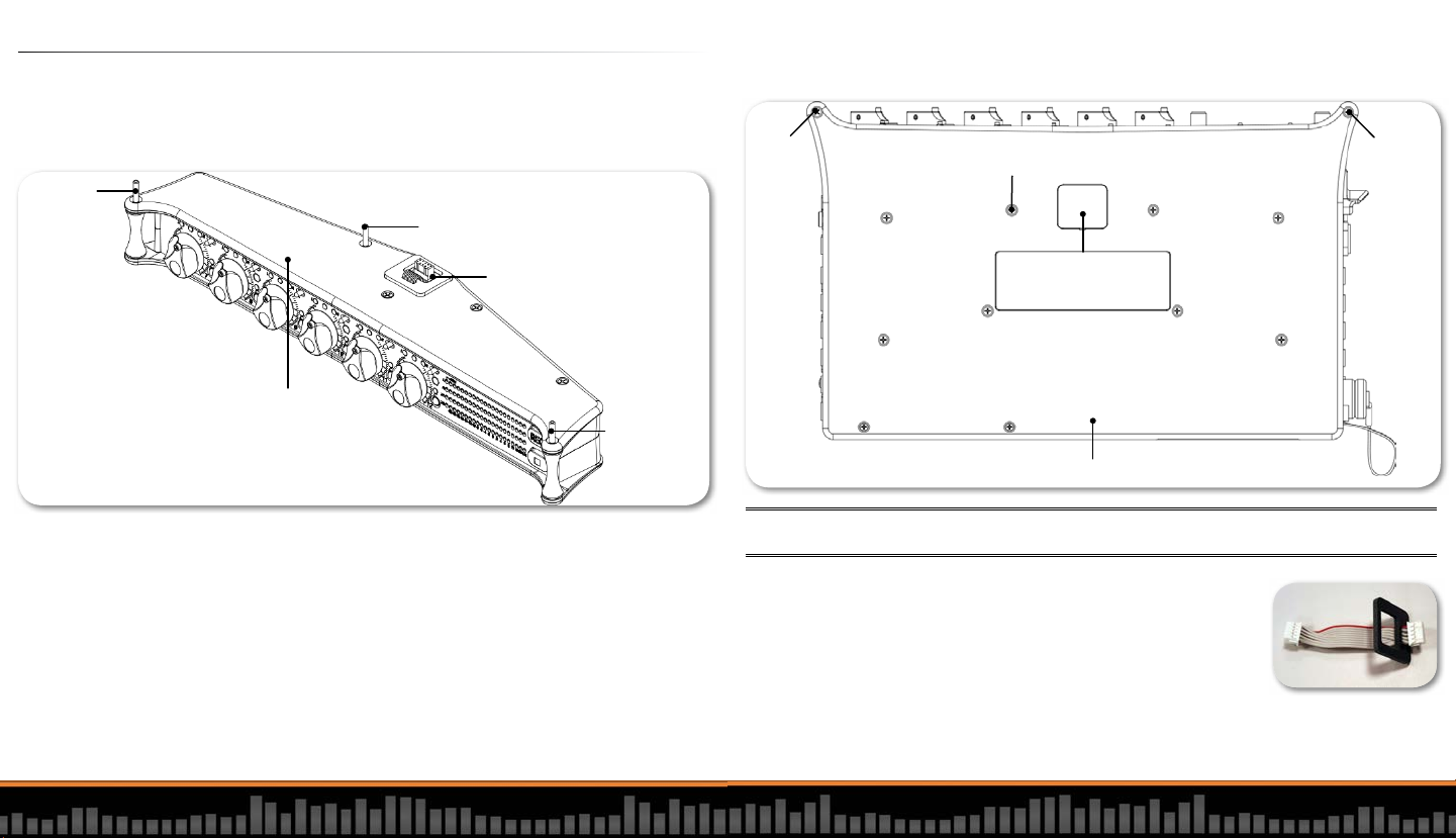
1. Attach CL-6 to the Mixer
Longer screw positioned
through opened rear channel
Longer
screw in
left front
corner
channel
Longer
screw in
right front
corner
channel
Multi-pin header (uncovered)
with ribbon cable and rubber
gasket in place
Top panel
Multi-pin header
(covered)
Bottom Panel of mixer (664 or 688)
Remove one
rear screw
Remove
left screw
Remove
right screw
The CL-6 was designed to mount on the 688 and 664 eld mixers. The CL-6 attaches with screws to
the bottom panel of the 688. When used with a 664, the CL-6 may be attached to either the top or
bottom panel of the mixer. Regardless of a top or bottom mount, the process for attaching the CL-6
remains the same. Tools needed to attach the accessory to your mixer include a small Phillips® (crosshead) screwdriver and a at tool, such as a jeweler’s screwdriver (not included).
4. Remove the one rear screw from the appropriate panel of the mixer, ensuring that it corresponds to
those already removed from the CL-6. Also remove the right and left screws from the front corners
of the mixer.
To attach the CL-6:
1. Turn the mixer off. If mixer is on, do not connect the CL-6.
2. Remove the disposable protective covers over the multi-pin headers from the appropriate panels
on the mixer and CL-6, using a small at tool. (A jeweler’s screwdriver works well.) The protective
covers are attached with adhesive.
3. Short rear screws are located on either side of the multi-pin headers on both the top and bottom
panels of the CL-6. Remove a rear screw to one side of the multi-pin header from the top panel,
and then remove the rear screw directly opposite its location from the bottom panel, so that a
clear channel through the device is opened for a single longer screw to slide through the device
and connect to the mixer. Two other longer screws, supplied with the accessory, will slide through
channels on both front right and left corners of the CL-6 (as shown).
4
CL-6
Note: Do not remove rear screws from both sides of the multi-pin header. The short screws removed in previous steps
will not be reused with the new assembly.
5. Connect the supplied ribbon cable (pictured here with its rubber gasket) to the multi-pin header on
the mixer.
6. Carefully slide the rubber gasket into place where the ribbon cable con-
nects to the mixer.
7. With the mixer positioned on a at, stable surface, hold the CL-6 in hand
and connect the other end of the ribbon cable to the CL-6.
8. Insert the excess ribbon cable into the cavity behind the header on the CL-6 while positioning the
CL-6 onto the mixer, aligning the screw holes on both devices. Ensure the ribbon cable is fully within the cavity and not pinched between the accessory and mixer.
Quick Start Guide
5
Page 4

9. Using a screwdriver, drive the three 2-inch long screws supplied with your accessory through the
Input Fader
L Mix
Indicator
Input
LED
PFL Switch
R Mix
Indicator
High-pass
Filter Button
High-pass
Filter LED
Stop Button
Record Button
Bus Track Arm LEDs
Bus Track Meter LEDs
on the CL-6
CL-6 and into the mixer—one in place of the rear screw and two others into the right and left front
corners.
Bottom Mount to 664
The CL-6 is shown here attached
to the bottom panel of the 664
eld production mixer.
Top Mount to 664
The CL-6 is shown here attached
to the top panel of the 664 eld
production mixer.
2. Power On
The CL-6 derives its power from the mixer to which it is attached.
Note: If a CL-6 is used with a 688 and the optional SL-6 powering and wireless system,
the SL-6 would be the primary power source for the CL-6.
To power on the CL-6:
▶ On the 664, ip the Power switch left to INT for internal battery power or
right to EXT for external DC power.
▶ On the 688, ip the Power switch to the ON position (as shown here).
The Power LED on the mixer illuminates yellow then green.
After the CL-6 is connected, inputs 7 through 12 have dedicated fader
controls, PFL switches and LEDs to indicate various input signal and track
activity. The CL-6 LED meters show L, R, X1, and X2 metering activity. Additional buttons are also
available for starting or stopping recordings and toggling the high-pass lter from on at 150 Hz to off.
Power LED
Bottom Mount to 688
The CL-6 is shown here attached
to the bottom panel of the 688
eld production mixer.
Note: Top mount of the CL-6 is not an
option for the 688.
6
CL-6
Quick Start Guide
7
Page 5

Warranty and Service
Sound Devices, LLC warrants the CL-6 against defects in materials and workmanship for a period of ONE (1) year from date of original
retail purchase. Users who register their product directly with Sound Devices Technical Support by mail, online, or phone, will receive an
additional ONE (1) year of warranty coverage, extending the complete warranty period to T WO (2) years from the date of original retail
purchase. In order to extend the warranty coverage period, registration must be completed within the initial ONE (1) year warranty period. Products must be purchased through authorized Sound Devices resellers to qualify for Warranty coverage. Damage resulting from
the opening of a Sound Devices product or attempted repairs by a non-authorized Sound Devices repair technician will void warranty
coverage.
This is a non-transferable warranty that extends only to the original purchaser. Sound Devices, LLC will repair or replace the product at its
discretion at no charge. Warranty claims due to severe service conditions will be addressed on an individual basis.
THE WARRANTY AND REMEDIES SET FORTH ABOVE ARE EXCLUSIVE. SOUND DEVICES, LLC DISCLAIMS ALL OTHER WARRANTIES, EXPRESS OR IMPLIED, INCLUDING WARRANTIES OF MERCHANTABILITY AND FITNESS FOR A PARTICULAR PURPOSE. SOUND DEVICES,
LLC IS NOT RESPONSIBLE FOR SPECIAL, INCIDENTAL, OR CONSEQUENTIAL DAMAGES ARISING FROM ANY BREACH OF WARRANT Y OR
UNDER ANY OTHER LEGAL THEORY. Because some jurisdictions do not permit the exclusion or limitations set forth above, they may not
apply in all cases.
For all service, including warranty repair, please contact Sound Devices for an RMA (return merchandise authorization) before sending
your unit in for repair. Product returned without an RMA number may experience delays in repair. When sending a unit for repair, please
do not include accessories, including SSD drives, CF cards, batteries, power supplies, carry cases, cables, or adapters unless instructed
by Sound Devices. Sound Devices repairs and replacements may be completed using refurbished, returned or used parts that have been
factory certied as functionally equivalent to new parts.
Sound Devices, LLC
Service Repair RMA #XXXXX
E7556 State Road 23 and 33
Reedsburg, WI 53959 USA
Telephone: (608) 524-0625
Technical Support / Bug Reports
For technical support and bug reporting on any Sound Devices products contact Sound Devices, LLC at:
Fill In and Keep for Your Records
PRODUCT: _____________________________________________
SERIAL NUMBER: _____________________________________________
PURCHASE DATE: _____________________________________________
STORE/RETAILER: _____________________________________________
ADDITIONAL NOTES: ___________________________________________________________________
___________________________________________________________________
___________________________________________________________________
___________________________________________________________________
___________________________________________________________________
___________________________________________________________________
Sound Devices recommends keeping your receipt, as well.
E-mail: support@sounddevices.com
Website: www.sounddevices.com/support/
Phone: +1 (608) 524-0625
Toll-free: +1 (800) 505-0625 — USA only
Fax: +1 (608) 524-0655
Sound Devices also hosts a user support forum. Visit: http://forum.sounddevices.com
8
CL-6
Quick Start Guide
9
Page 6

Legal Notes
Product specifications and features are subject to change without prior notification.
Copyright © 2015
Sound Devices, LLC.
All rights reserved.
This document is protected under copyright law. An authorized licensee of this product may reproduce this publication for the licensee’s
own personal use. This document may not be reproduced or distributed, in whole or in par t, for commercial purposes, such as selling
copies or providing educational services or support. This document is supplied as a technical guide for CL-6. Special care has been taken
in preparing the information for publication; however, since product specications are subject to change, this document might contain
omissions and technical or typographical inaccuracies. Sound Devices, LLC does not accept responsibility for any losses due to the use
of this guide.
Limitation of Liability
LIMITATION ON SOUND DEVICES’ LIABILITY. SOUND DEVICES, LLC SHALL NOT BE LIABLE TO THE PURCHASER OF THIS PRODUCT OR
THIRD PARTIES FOR DAMAGES, LOSSES, COSTS, OR EXPENSES INCURRED BY PURCHASER OR THIRD PARTIES AS A RESULT OF: ACCIDENT, MISUSE, OR ABUSE OF THIS PRODUCT OR UNAUTHORIZED MODIFICATIONS, REPAIRS, OR ALTERATIONS TO THIS PRODUCT, OR
FAILURE TO STRICTLY COMPLY WITH SOUND DEVICES, LLC’S OPERATING AND INSTALLATION INSTRUCTIONS. TO THE FULLEST EXTENT
PERMITTED BY LAW, SOUND DEVICES SHALL HAVE NO LIABILITY TO THE END USER OR ANY OTHER PERSON FOR COSTS, EXPENSES,
DIRECT DAMAGES, INCIDENTAL DAMAGES, PUNITIVE DAMAGES, SPECIAL DAMAGES, CONSEQUENTIAL DAMAGES OR OTHER DAMAGES
OF ANY KIND OR NATURE WHATSOEVER ARISING OUT OF OR RELATING TO THE PRODUCTS, THESE TERM(S) AND CONDITIONS OR THE
PARTIES’ RELATIONSHIP, INCLUDING, WITHOUT LIMITATION, DAMAGES RESULTING FROM OR RELATED TO THE DELETION OR OTHER
LOSS OF AUDIO OR VIDEO RECORDINGS OR DATA, REDUCED OR DIMINISHED AUDIO OR VIDEO QUALITY OR OTHER SIMILAR AUDIO OR
VIDEO DEFECTS ARISING FROM, RELATED TO OR OTHERWISE ATTRIBUTABLE TO THE PRODUCTS OR THE END USER’S USE OR OPERATION
THEREOF, REGARDLESS OF WHETHER SUCH DAMAGES ARE CLAIMED UNDER CONTRACT, TORT OR ANY OTHER THEORY. “CONSEQUENTIAL DAMAGES” FOR WHICH SOUND DEVICES SHALL NOT BE LIABLE SHALL INCLUDE, WITHOUT LIMITATION, LOST PROFITS, PENALTIES,
DELAY DAMAGES, LIQUIDATED DAMAGES AND OTHER DAMAGES AND LIABILITIES WHICH END USER SHALL BE OBLIGATED TO PAY OR
WHICH END USER OR ANY OTHER PARTY MAY INCUR RELATED TO OR ARISING OUT OF ITS CONTRACTS WITH ITS CUSTOMERS OR OTHER
THIRD PARTIES. NOTWITHSTANDING AND WITHOUT LIMITING THE FOREGOING, IN NO EVENT SHALL SOUND DEVICES BE LIABLE FOR
ANY AMOUNT OF DAMAGES IN EXCESS OF AMOUNTS PAID BY THE END USER FOR THE PRODUCTS AS TO WHICH ANY LIABILITY HAS BEEN
DETERMINED TO EXIST. SOUND DEVICES AND END USER EXPRESSLY AGREE THAT THE PRICE FOR THE PRODUCTS WAS DETERMINED
IN CONSIDERATION OF THE LIMITATION ON LIABILITY AND DAMAGES SET FORTH HEREIN AND SUCH LIMITATION HAS BEEN SPECIFICALLY
BARGAINED FOR AND CONSTITUTES AN AGREED ALLOCATION OF RISK WHICH SHALL SURVIVE THE DETERMINATION OF ANY COURT OF
COMPETENT JURISDICTION THAT ANY REMEDY HEREIN FAILS OF ITS ESSENTIAL PURPOSE.
Trademarks
The “wave” logo is a registered trademark of of Sound Devices, LLC.
FCC Notice
This device complies with part 15 of the FCC Rules. Operation is subject to the following two conditions: (1) This device may not cause
harmful interference, and (2) This device must accept any interference received, including interference that may cause undesired
operation.
FCC Part 15.19 (a)(3)
Declaration of Conformity
According to EN ISO/IEC 17050-1:2004
Manufacturer’s Name: Sound Devices, LLC
Manufacturer’s Address: E7556 State Road 23 and 33
Reedsburg, WI 53959
USA
Declares under sole responsibility that the product as delivered
Product Name: CL-6 Input Controller
Model Number: CL-6
Product Options: This declaration covers all options of the above product.
complies with the essential requirements of the following applicable European Directives,
and carries the CE marking accordingly:
EMC Directive (2004/108/EC)
EN 55022:2010
EN 55103-2:2009
First date of CE approval October 17, 2012.
This Declaration of Conformity applies to the above-listed product(s) placed on the EU market after:
October 17, 2012
Date Matt Anderson
President
10
CL-6
Quick Start Guide
11
Page 7

www.sounddevices.com
Part # 6553.001
 Loading...