

Page 1
788T
High Resolution Digital Audio Recorder with Time Code
User Guide and Technical Information
for 788T and 788T-SSD Recorders
Version 3.02
Sound Devices, LLC
E7556 State Rd. 23 and 33 • Reedsburg, WI • USA
+1 (608) 524-0625 • fax: +1 (608) 524-0655
Toll-Free: (800) 505-0625
www.sounddevices.com
support@sounddevices.com
USB
S ATA
2.5"
2.0
UDMA
Page 2

Page 3
788T/788T-SSD User Guide and Technical Information
Chapter 1: Quick Start Guide
Chapter 2: Panel and LCD Descriptions
Front Panel Descriptions . . . . . . . . . . . . . . . . . . 8
Panel Lock . . . . . . . . . . . . . . . . . . . . . . . . . . . . 11
Left Panel Connectors and Controls . . . . . . . . . 11
Right Panel Connectors and Controls . . . . . . . . 12
Rear Panel Descriptions . . . . . . . . . . . . . . . . . . 13
LCD Display Descriptions . . . . . . . . . . . . . . . . . 14
Input Settings Window Descriptions . . . . . . . . . 17
Chapter 3: Inputs and Outputs
Input Setup and Control . . . . . . . . . . . . . . . . . 26
Input Trim and Input Faders . . . . . . . . . . . . . . . . . . 26
Input Settings Window . . . . . . . . . . . . . . . . . . . . . 27
Analog Inputs . . . . . . . . . . . . . . . . . . . . . . . . . . 30
Input Linking (Stereo or MS Decoding) . . . . . . . . . . . 30
Digital Inputs . . . . . . . . . . . . . . . . . . . . . . . . . . . 31
AES42 Digital Microphones . . . . . . . . . . . . . . . . . . 31
Input Delay . . . . . . . . . . . . . . . . . . . . . . . . . . . 31
Deactivate Inputs . . . . . . . . . . . . . . . . . . . . . . . . 32
Chapter 4: Routing and Mixing
Input to Track Routing . . . . . . . . . . . . . . . . . . . 34
Pre-Fade vs. Post Fade . . . . . . . . . . . . . . . . . . . . . 34
Routing Using the Input Settings Window . . . . . . . . . . 35
Routing Using the Setup Menu . . . . . . . . . . . . . . . . 36
Routing Using The Track Setup Window . . . . . . . . . . . 37
Routing Using the CL-8 . . . . . . . . . . . . . . . . . . . . 38
Routing Using the CL-9 . . . . . . . . . . . . . . . . . . . . . 38
Track Setup Window . . . . . . . . . . . . . . . . . . . . 18
Track Level Meters View . . . . . . . . . . . . . . . . . . . . 19
Track Routing View . . . . . . . . . . . . . . . . . . . . . . . 20
Track-to-Media View . . . . . . . . . . . . . . . . . . . . . . 20
Master Gain Levels View . . . . . . . . . . . . . . . . . . . . 21
Take List Descriptions . . . . . . . . . . . . . . . . . . . 22
Drive Directory (File Viewer) Descriptions . . . . . 24
Root Directory . . . . . . . . . . . . . . . . . . . . . . . . . . 25
Outputs – Analog and Digital . . . . . . . . . . . . . 32
Output Routing . . . . . . . . . . . . . . . . . . . . . . . . . 32
Output Types . . . . . . . . . . . . . . . . . . . . . . . . . . 33
Output Delay . . . . . . . . . . . . . . . . . . . . . . . . . . 33
Mix Assist™ . . . . . . . . . . . . . . . . . . . . . . . . . . . 38
Noise Adaptive Threshold . . . . . . . . . . . . . . . . . . . 38
Number of Open Microphone Attenuation . . . . . . . . 38
Last Mic Lock-On . . . . . . . . . . . . . . . . . . . . . . . . 39
One Mic Per Sound Source . . . . . . . . . . . . . . . . . . 39
Using Mix Assist . . . . . . . . . . . . . . . . . . . . . . . . . 39
Introduction
Table of Contents
Chapter 5: Recording and Playback
Pre-Record Buffer . . . . . . . . . . . . . . . . . . . . . . . . 40
Media Select . . . . . . . . . . . . . . . . . . . . . . . . . . . 40
Failure During Recording . . . . . . . . . . . . . . . . . . . 41
Record Timer . . . . . . . . . . . . . . . . . . . . . . . . . . . 41
Track Arming . . . . . . . . . . . . . . . . . . . . . . . . . 41
Track Enabling Using the CL-9 . . . . . . . . . . . . . . . . 42
Track Status Indication . . . . . . . . . . . . . . . . . . . . . 42
Track-to-Media Routing . . . . . . . . . . . . . . . . . . . . 42
Master Gain Levels . . . . . . . . . . . . . . . . . . . . . . . 43
Track Limiters . . . . . . . . . . . . . . . . . . . . . . . . . . . 44
Master Gain Levels Using the CL-9 . . . . . . . . . . . . . . 44
Sampling Rate and Bit Depth . . . . . . . . . . . . . 44
Sampling Rate . . . . . . . . . . . . . . . . . . . . . . . . . . 45
Bit Depth . . . . . . . . . . . . . . . . . . . . . . . . . . . . . 46
Audio File Formats . . . . . . . . . . . . . . . . . . . . . 47
.WAV . . . . . . . . . . . . . . . . . . . . . . . . . . . . . . . 47
File Type . . . . . . . . . . . . . . . . . . . . . . . . . . . . . . 47
i
Page 4

788T/788T-SSD User Guide and Technical Information
Take Management . . . . . . . . . . . . . . . . . . . . . 47
Scene Name/Numbering . . . . . . . . . . . . . . . . . . . 48
Scene Name Incrementing/Decrementing . . . . . . . . . 49
Take Numbers . . . . . . . . . . . . . . . . . . . . . . . . . . 51
Take Number Incrementing/Decrementing . . . . . . . . . 51
False Take Control . . . . . . . . . . . . . . . . . . . . . . . 52
Emptying the False Take Folders . . . . . . . . . . . . . . . 52
Track Naming . . . . . . . . . . . . . . . . . . . . . . . . . . 53
Metadata Implementation . . . . . . . . . . . . . . . 53
Chapter 6: Synchronization and Timecode
Synchronization . . . . . . . . . . . . . . . . . . . . . . . . 63
Clock Master . . . . . . . . . . . . . . . . . . . . . . . . . . 63
Word Out . . . . . . . . . . . . . . . . . . . . . . . . . . . . 63
AES Digital Outputs . . . . . . . . . . . . . . . . . . . . . . . 63
Clock Slave . . . . . . . . . . . . . . . . . . . . . . . . . . . . 63
Internal . . . . . . . . . . . . . . . . . . . . . . . . . . . . . . 64
Table of Contents
Word Clock Input . . . . . . . . . . . . . . . . . . . . . . . . 64
Video Sync . . . . . . . . . . . . . . . . . . . . . . . . . . . . 64
Digital Inputs 1-2, 3-4, 5-6, 7-8 . . . . . . . . . . . . . . . 64
Take List . . . . . . . . . . . . . . . . . . . . . . . . . . . . . 54
Take Edit Menu . . . . . . . . . . . . . . . . . . . . . . . . . 55
Wave Agent Metadata Entry and Editing . . . . . . . . . . 59
CL-WiFi Metering and Display . . . . . . . . . . . . . . . . . 59
CSV Sound Reports . . . . . . . . . . . . . . . . . . . . . 59
Sound Report Setup . . . . . . . . . . . . . . . . . . . . . . . 59
Generating Sound Reports . . . . . . . . . . . . . . . . . . 61
Sound Report Best Practices . . . . . . . . . . . . . . . . . . 61
Playback . . . . . . . . . . . . . . . . . . . . . . . . . . . . 62
AutoPlay . . . . . . . . . . . . . . . . . . . . . . . . . . . . . 62
Time Code . . . . . . . . . . . . . . . . . . . . . . . . . . . . 65
Frame Rate . . . . . . . . . . . . . . . . . . . . . . . . . . . 65
F Sampling Rate Modes . . . . . . . . . . . . . . . . . . . . 66
Time Code Modes . . . . . . . . . . . . . . . . . . . . . . . 67
Time Code Hold Off . . . . . . . . . . . . . . . . . . . . . . 69
Jam Menu . . . . . . . . . . . . . . . . . . . . . . . . . . . . 70
User Bits . . . . . . . . . . . . . . . . . . . . . . . . . . . . . 71
NTSC Standard Def Video Production . . . . . . . . . . . 71
Chapter 7: Monitoring and Metering
Headphone Output . . . . . . . . . . . . . . . . . . . . . 72
Selecting Headphone Sources . . . . . . . . . . . . . . . . 72
Setting Headphone Source Options . . . . . . . . . . . . . 72
Headphone Source as Outputs . . . . . . . . . . . . . . . 74
Input Solo (PFL) . . . . . . . . . . . . . . . . . . . . . . . . . 74
MS Stereo Monitoring . . . . . . . . . . . . . . . . . . . . . 75
SoundField B-Format Surround Monitoring . . . . . . . . 75
Rotary Switch Behavior . . . . . . . . . . . . . . . . . . . . . 76
Headphone Favorite Selection . . . . . . . . . . . . . . . . 76
Headphone Playback Mode . . . . . . . . . . . . . . . . . 76
Headphone Warning Tones . . . . . . . . . . . . . . . . . . 76
Headphone Power Up Gain . . . . . . . . . . . . . . . . . . 76
CL-9 Headphone Monitoring . . . . . . . . . . . . . . . . . 76
Metering and Display . . . . . . . . . . . . . . . . . . . 77
Output Meter . . . . . . . . . . . . . . . . . . . . . . . . . . 77
Meter Scale . . . . . . . . . . . . . . . . . . . . . . . . . . . . 77
Digital Meter View . . . . . . . . . . . . . . . . . . . . . . . . 79
Meter Ballistics . . . . . . . . . . . . . . . . . . . . . . . . . 79
Peak Hold Time . . . . . . . . . . . . . . . . . . . . . . . . . 80
Input Activity Ring LEDs . . . . . . . . . . . . . . . . . . . . 80
Headphone Peak LED . . . . . . . . . . . . . . . . . . . . . 80
Tone Oscillator . . . . . . . . . . . . . . . . . . . . . . . . . 81
LCD Contrast & LED Brightness . . . . . . . . . . . . . . . 81
LCD Backlight . . . . . . . . . . . . . . . . . . . . . . . . . . 81
CL-2 Metering and Display . . . . . . . . . . . . . . . . . . 82
CL-8 Metering and Display . . . . . . . . . . . . . . . . . . 82
CL-9 Metering and Display . . . . . . . . . . . . . . . . . . 82
Wave Agent Metering and Display . . . . . . . . . . . . . . 83
CL-WiFi Metering and Display . . . . . . . . . . . . . . . . . 83
Chapter 8: File Management and Storage
Automatic File Splitting . . . . . . . . . . . . . . . . . . . . . 84
File Time and Date . . . . . . . . . . . . . . . . . . . . . . . 84
Folder Actions . . . . . . . . . . . . . . . . . . . . . . . . . . 84
ii
v. 3.02 Features and specifications are subject to change. Visit www.sounddevices.com for the latest documentation.
Page 5
788T/788T-SSD User Guide and Technical Information
The Drive Directory (File Viewer) . . . . . . . . . . . 85
Navigation . . . . . . . . . . . . . . . . . . . . . . . . . . . . 86
Selecting Files for Playback . . . . . . . . . . . . . . . . . . 87
Folder Options Menu . . . . . . . . . . . . . . . . . . . . . . 87
File Options Menu . . . . . . . . . . . . . . . . . . . . . . . 88
Drive Directory Options Menu . . . . . . . . . . . . . . . . 88
Storage Media – Internal Drive . . . . . . . . . . . . 91
788T Drive Type . . . . . . . . . . . . . . . . . . . . . . . . 91
788T-SSD Drive Type . . . . . . . . . . . . . . . . . . . . . . 91
Drive Replacement . . . . . . . . . . . . . . . . . . . . . . . 91
Chapter 9: Remote Control
Keyboard Assignments . . . . . . . . . . . . . . . . . . . . . 99
Logic In . . . . . . . . . . . . . . . . . . . . . . . . . . . . . 102
Logic Out (Record Tally) . . . . . . . . . . . . . . . . . . . 102
Multi-Unit Linking Via C. Link . . . . . . . . . . . . 102
C.Link Setup Procedure . . . . . . . . . . . . . . . . . . . . 104
C.Link Metadata Sharing (788T Only) . . . . . . . . . . . 105
Wave Agent Control . . . . . . . . . . . . . . . . . . . . 105
Storage Medium – Removable CompactFlash . . 92
When to Use CF . . . . . . . . . . . . . . . . . . . . . . . . 92
Formatting . . . . . . . . . . . . . . . . . . . . . . . . . . . . 92
Qualified CF Cards . . . . . . . . . . . . . . . . . . . . . . 93
Storage Medium – External FireWire Drives . . . 93
When to Use External FireWire Drives . . . . . . . . . . . . 93
Formatting . . . . . . . . . . . . . . . . . . . . . . . . . . . . 93
FireWire Bus Powering . . . . . . . . . . . . . . . . . . . . . 94
Qualified Drives . . . . . . . . . . . . . . . . . . . . . . . . 94
DVD-RAM Drives . . . . . . . . . . . . . . . . . . . . . . . . 94
File Copying Among Available Media . . . . . . . 94
File Transfer to Computer . . . . . . . . . . . . . . . . 96
CL-WIFI . . . . . . . . . . . . . . . . . . . . . . . . . . . . . 106
Connecting the CL-WIFI . . . . . . . . . . . . . . . . . . . 107
Configuring the CL-WIFI . . . . . . . . . . . . . . . . . . . 107
Configuring Apple iOS Wi-Fi Settings . . . . . . . . . . . 108
CL-WiFi Application for Apple iOS . . . . . . . . . . . . . 110
Transport View . . . . . . . . . . . . . . . . . . . . . . . . . 110
Take List . . . . . . . . . . . . . . . . . . . . . . . . . . . . . 112
Routing . . . . . . . . . . . . . . . . . . . . . . . . . . . . . 113
Chapter 10: Hardware Controllers
CL-1 Keyboard and Remote Control Interface . 114
CL-2 Remote Fader (optional) . . . . . . . . . . . . . 116
CL-2 Connection . . . . . . . . . . . . . . . . . . . . . . . 116
CL-2 Panel Descriptions . . . . . . . . . . . . . . . . . . . 117
Fader Assignment . . . . . . . . . . . . . . . . . . . . . . . 118
CL-2 Switches . . . . . . . . . . . . . . . . . . . . . . . . . 118
CL-8 Controller (optional) . . . . . . . . . . . . . . . . 120
CL-8 Connection . . . . . . . . . . . . . . . . . . . . . . . 120
CL-8 Front Panel Descriptors . . . . . . . . . . . . . . . . 121
CL-8 Side Panel Descriptors . . . . . . . . . . . . . . . . . 122
CL-8 Back Panel Descriptors. . . . . . . . . . . . . . . . . 122
CL-8 Fader Control . . . . . . . . . . . . . . . . . . . . . . 123
CL-8 Views . . . . . . . . . . . . . . . . . . . . . . . . . . . 123
Slate Mic . . . . . . . . . . . . . . . . . . . . . . . . . . . . 124
CL-9 Linear Fader Controller (optional) . . . . . 127
CL-9 Connection . . . . . . . . . . . . . . . . . . . . . . . 127
CL-9 Rear Panel Descriptors . . . . . . . . . . . . . . . . . 130
CL-9 Fader Control . . . . . . . . . . . . . . . . . . . . . 130
CL-9 Master Gain Level Controls . . . . . . . . . . . . . 131
CL-9 Headphone Monitor . . . . . . . . . . . . . . . . . 132
Setup Menu Navigation From CL-9 . . . . . . . . . . . . 132
Soloing Inputs. Outputs, or Tracks . . . . . . . . . . . . . 133
EQ . . . . . . . . . . . . . . . . . . . . . . . . . . . . . . . 133
Pan . . . . . . . . . . . . . . . . . . . . . . . . . . . . . . . 133
Encoder Acceleration . . . . . . . . . . . . . . . . . . . . . 133
CL-9 Mode Basics . . . . . . . . . . . . . . . . . . . . . . 134
Factory Modes . . . . . . . . . . . . . . . . . . . . . . . . . 134
User Modes (U1-U4) . . . . . . . . . . . . . . . . . . . . . 137
CL-9 Input-to-Track Routing . . . . . . . . . . . . . . . . . 139
CL-9 Communications . . . . . . . . . . . . . . . . . . . 140
CL-9 Transport Control . . . . . . . . . . . . . . . . . . . 145
CL-9 Footswitch . . . . . . . . . . . . . . . . . . . . . . . . 145
CL-9 LED Brightness . . . . . . . . . . . . . . . . . . . . . 145
CL-9 Specifications . . . . . . . . . . . . . . . . . . . . . . 145
CL-WIFI . . . . . . . . . . . . . . . . . . . . . . . . . . . . . 146
Table of Contents
iii
Page 6

788T/788T-SSD User Guide and Technical Information
Chapter 11: Setup and Shortcut Reference
Setup Menu . . . . . . . . . . . . . . . . . . . . . . . . . 148
Saving and Recalling User Settings . . . . . . . . . . . . 158
Setup Menu Shortcuts . . . . . . . . . . . . . . . . . . . . 158
Chapter 12: Specifications
Connector Pin Assignments . . . . . . . . . . . . . . 163
Chapter 13: Accessories
Included Accessories . . . . . . . . . . . . . . . . . . . . . 165
Optional Accessories . . . . . . . . . . . . . . . . . . . . . 165
Chapter 14: Appendix
Software License . . . . . . . . . . . . . . . . . . . . . . 167
Warranty & Service . . . . . . . . . . . . . . . . . . . . 168
Technical Support / Bug Reports . . . . . . . . . . 168
Introduction
788T CE Declaration of Conformity . . . . . . . . . 169
Front Panel Button Shortcuts . . . . . . . . . . . . . 159
iv
Welcome
Thank you for purchasing the 788T/788T-SSD. The ultra-compact 788T records and plays back up
to 12 tracks of audio to and from its internal drive, CompactFlash, or external drives, making fi eld
recording simple and fast. It writes and reads uncompressed PCM audio at 16 or 24 bits with sampling rates between 32 kHz and 192 kHz. The time code implementation makes the 788T ready for
any recording job—from over-the-shoulder to cart-based production.
The 788T implements a no-compromise audio path that includes Sound Devices’ high-performance
microphone preamplifi ers. Designed specifi cally for high bandwidth, high bit rate digital recording,
these preamps set a new standard for frequency response linearity, low distortion performance, and
low noise.
With documentary and ENG mixing engineers in mind, the 788T is very small, while still being
feature-rich. No other recorder on the market matches its size and feature set. In addition, its learning curve is quite short—powerful does not mean complicated.
v. 3.02 Features and specifications are subject to change. Visit www.sounddevices.com for the latest documentation.
Page 7
788T/788T-SSD User Guide and Technical Information
Sound Devices took advantage of the best in professional and consumer electronic technologies to
bring incredible feature depth with ease of use. Hard drives, SSD drives, and CompactFlash are
highly reliable, industry standard, and easily obtainable. With the ability to write to an external
drive, low-cost, portable media can be delivered to post production. The removable, rechargeable
battery is a standard Sony-compatible Li-ion camcorder battery pack. The 788T interconnects with
Windows and Mac OS computers for convenient data transfer and backup.
The 788T is available in two models, The standard 788T ships with an internal hard drive. The 788TSSD ships with an internal solid state drive. Throughout this document both models will be referred
to as the 788T, except when information is specifi c to each model.
788T and 788T-SSD Firmware Known Issues
For a complete list of any known issues: www.sounddevices.com/download/788t-fi rmware.htm.
Copyright Notice and Release
All rights reserved. No part of this publication may be reproduced, stored in a retrieval system, or transmitted in any form or by any
means, electronic, mechanical, photocopying, recording, or otherwise, without the expressed written permission of SOUND DEVICES,
LLC. SOUND DEVICES is not responsible for any use of this information.
Microsoft Windows is a registered trademark of Microsoft Corporation. Macintosh is a registered trademark of Apple Computer. Other
product and company names mentioned herein may be the trademarks of their respective owners.
The sound waves logo is a registered trademark of Sound Devices, LLC.
Limitation of Liability
LIMITATION ON SOUND DEVICES’ LIABILITY. SOUND DEVICES, LLC SHALL NOT BE LIABLE TO THE PURCHASER OF THIS
PRODUCT OR THIRD PARTIES FOR DAMAGES, LOSSES, COSTS, OR EXPENSES INCURRED BY PURCHASER OR THIRD PARTIES AS A RESULT OF: ACCIDENT, MISUSE, OR ABUSE OF THIS PRODUCT OR UNAUTHORIZED MODIFICATIONS, REPAIRS,
OR ALTERATIONS TO THIS PRODUCT, OR FAILURE TO STRICTLY COMPLY WITH SOUND DEVICES, LLC’S OPERATING AND
INSTALLATION INSTRUCTIONS. TO THE FULLEST EXTENT PERMITTED BY LAW, SOUND DEVICES SHALL HAVE NO LIABILITY
TO THE END USER OR ANY OTHER PERSON FOR COSTS, EXPENSES, DIRECT DAMAGES, INCIDENTAL DAMAGES, PUNITIVE
DAMAGES, SPECIAL DAMAGES, CONSEQUENTIAL DAMAGES OR OTHER DAMAGES OF ANY KIND OR NATURE WHATSOEVER
ARISING OUT OF OR RELATING TO THE PRODUCTS, THESE TERMS AND CONDITIONS OR THE PARTIES’ RELATIONSHIP,
INCLUDING, WITHOUT LIMITATION, DAMAGES RESULTING FROM OR RELATED TO THE DELETION OR OTHER LOSS OF AUDIO
OR VIDEO RECORDINGS OR DATA, REDUCED OR DIMINISHED AUDIO OR VIDEO QUALITY OR OTHER SIMILAR AUDIO OR
VIDEO DEFECTS ARISING FROM, RELATED TO OR OTHERWISE ATTRIBUTABLE TO THE PRODUCTS OR THE END USER’S USE
OR OPERATION THEREOF, REGARDLESS OF WHETHER SUCH DAMAGES ARE CLAIMED UNDER CONTRACT, TORT OR ANY
OTHER THEORY. “CONSEQUENTIAL DAMAGES” FOR WHICH SOUND DEVICES SHALL NOT BE LIABLE SHALL INCLUDE, WITHOUT LIMITATION, LOST PROFITS, PENALTIES, DELAY DAMAGES, LIQUIDATED DAMAGES AND OTHER DAMAGES AND LIABILITIES WHICH END USER SHALL BE OBLIGATED TO PAY OR WHICH END USER OR ANY OTHER PARTY MAY INCUR RELATED TO
OR ARISING OUT OF ITS CONTRACTS WITH ITS CUSTOMERS OR OTHER THIRD PARTIES. NOTWITHSTANDING AND WITHOUT
LIMITING THE FOREGOING, IN NO EVENT SHALL SOUND DEVICES BE LIABLE FOR ANY AMOUNT OF DAMAGES IN EXCESS
OF AMOUNTS PAID BY THE END USER FOR THE PRODUCTS AS TO WHICH ANY LIABILITY HAS BEEN DETERMINED TO EXIST.
SOUND DEVICES AND END USER EXPRESSLY AGREE THAT THE PRICE FOR THE PRODUCTS WAS DETERMINED IN CONSIDERATION OF THE LIMITATION ON LIABILITY AND DAMAGES SET FORTH HEREIN AND SUCH LIMITATION HAS BEEN SPECIFICALLY BARGAINED FOR AND CONSTITUTES AN AGREED ALLOCATION OF RISK WHICH SHALL SURVIVE THE DETERMINATION
OF ANY COURT OF COMPETENT JURISDICTION THAT ANY REMEDY HEREIN FAILS OF ITS ESSENTIAL PURPOSE.
Introduction
v
Page 8

Page 9
788T/788T-SSD User Guide and Technical Information
1
Quick Start Guide
This Quick Start Guide provides a brief overview for fi rst use of the 788T/788T-SSD. The Quick Start
Guide walks through the steps of getting signal into the 788T and making a recording. Many operational and relevant technical and operational details are not mentioned in these steps. For detailed
operating instructions refer to the 788T/788T-SSD User Guide and Technical Information.
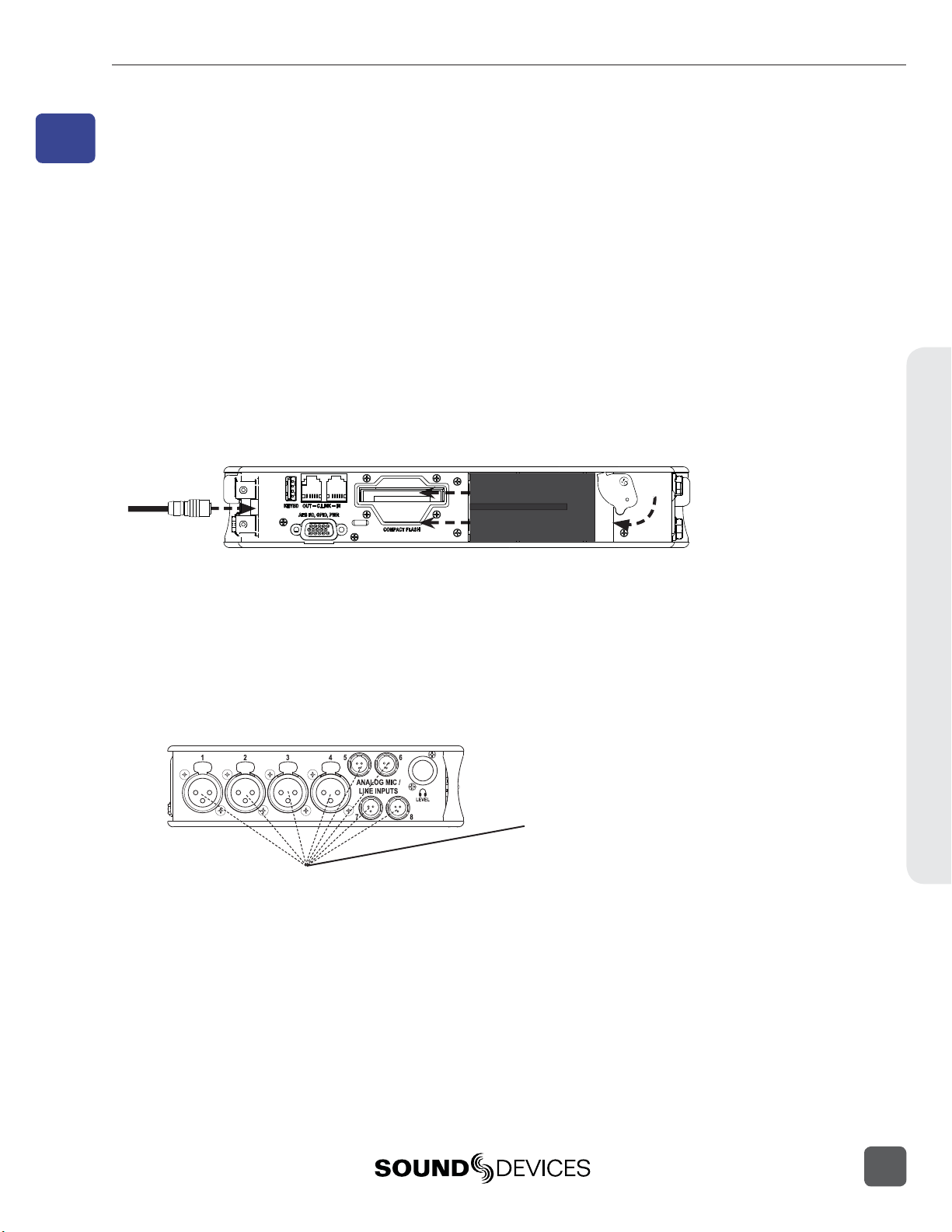
1. Connect Power.
Connect the supplied AC-to-DC power supply to the DC connector on the
Right Panel.
2.
Attach the supplied Li-ion rechargeable battery to the recorder.
Line up battery contacts with the battery compartment mounting pins. Rotate
battery lock to secure the battery in place.
Included L-Mount Battery
788T Rear Panel
The included battery must be charged for six hours before initial use.
The 788T will charge the L-Mount battery when DC is connected.
3. Connect analog microphone or line sources.
Please refer to the 788T/788T-SSD User Guide and Technical Information for
connections with digital audio sources.
788T Left Panel
Quick Start Guide
1
Page 10
788T/788T-SSD User Guide and Technical Information
4. Connect headphones
Connect to either the 1/4-inch or 1/8-inch headphone output on the Right
Panel.
WORD/ VID IN
DCIN
MENU
SELECT
1
23
ANALOG BALLINE OUTS
UNBAL
5,6
FW800
FW400
USB
BALAES
OUT
4
1,2 3,4
TIMECODE
10-18V
SYNC
788T Right Panel
()
+
PIN4
-
()
PIN1
WORDOUT
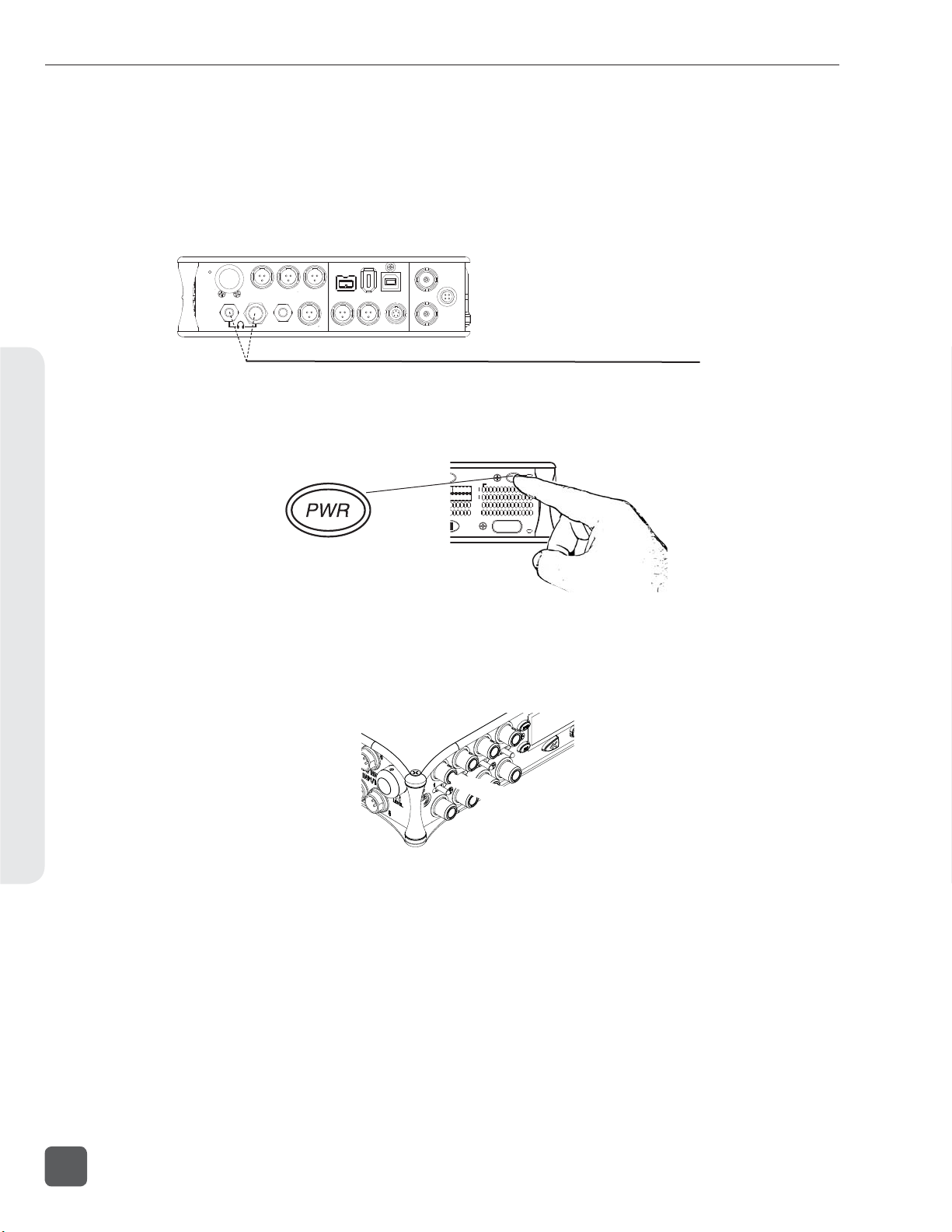
5. Press and hold the PWR key for one second to power on.
Quick Start Guide
788T
0
d
BFS
PWR
ARM
C
D
E
F
REC
0
d
BFS
T
6. INPUTS MUST BE ACTIVE TO BE RECORDED.
Push to release the recessed Input Gain Controls. Rotate the knob clockwise
past the detent to turn on the input.
In the full counter-clockwise position, the input is not active and is not available for use.
2
v. 3.02 Features and specifications are subject to change. Visit www.sounddevices.com for the latest documentation.
Page 11
1
2
788T/788T-SSD User Guide and Technical Information
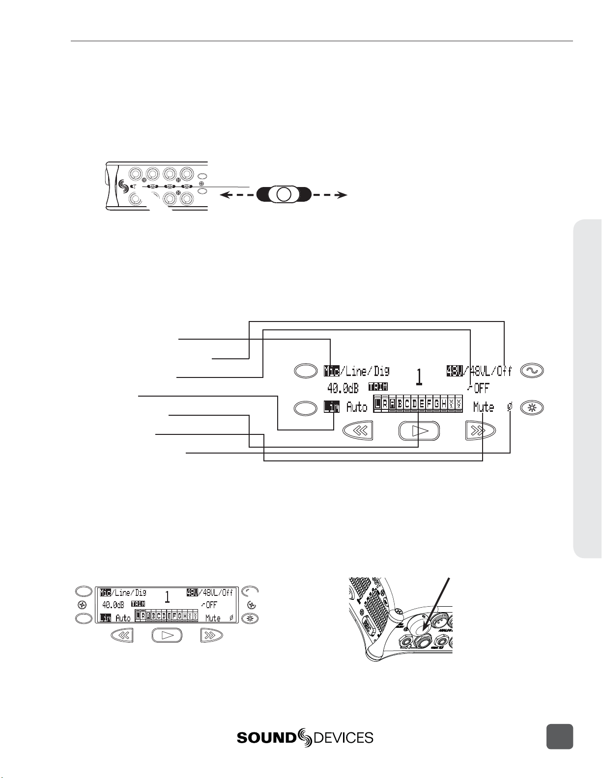
7. Access the Input Settings Window
To access, momentarily move the Input Selector Switch in the direction of
the Input. This action also sends the input signal to the headphone monitor
(solo).
3
1
5
4
2
MENU
7
8
6
HDD
Input Setting Options:
Source (mic/line/digital)
Phantom (on (mic)/on (line)/off)
High-Pass Filter (on/off)
Limiter (on/off)
Input-to-Track Routing
Mute (none / mute)
Polarity (normal / reverse)
Left for odd inputs
Right for even inputs
MENU
HDD
Quick Start Guide
Press adjacent key to change the parameter.
8. The Input Settings Window is where changes are made to input parameters.
Press the TONE key to toggle Phantom Power (Choose 48V for microphones).
Turn the Rotary Switch to adjust the High-Pass Filter Frequency.
Turn the Rotary Switch
MENU
HDD
3
Page 12
A
B
R
L
788T/788T-SSD User Guide and Technical Information
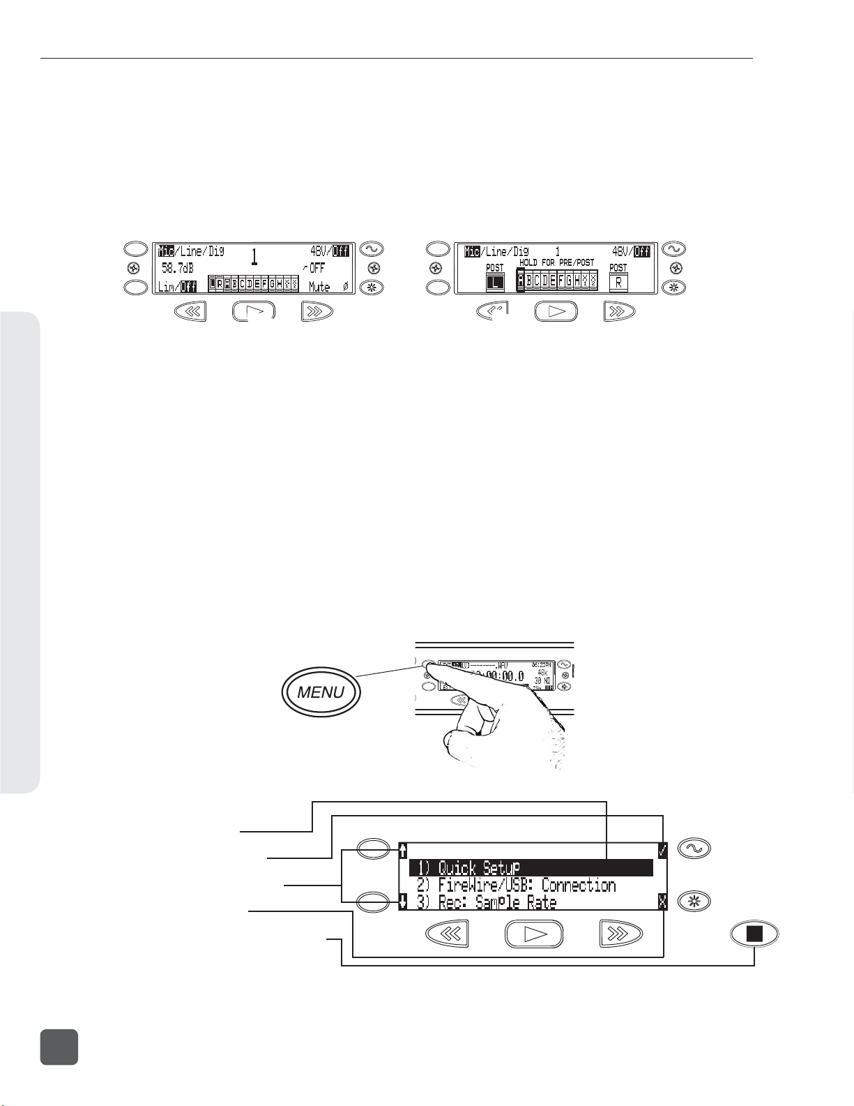
9. INPUTS MUST BE ROUTED TO TRACKS TO RECORD.
From the Input Settings Window, press the PLAY key to enter Input-to-Track
Routing. An Input can be assigned to any Track. The Rewind and Fast-Forward keys route inputs to Track L and R, respectively. Turn the Rotary Switch
to select a Track from A to X2. Push in on the Rotary Switch to route the input
to the track. Press PLAY again to return to the Input Settings Window.
Quick Start Guide
MENU
HDD
Press PLAY to enter
Input-to-Track routing.
Press again to exit.
MENU
HDD
Press REW to route to
Track L, Press FF to
route to Track R. Use the
Rotary Switch to route to
Tracks A - X2.
10. Return to the Main Display.
Momentarily move the Input Selector Switch again.
11.
Press the MENU key to enter the Setup Menu.
Various options are confi gured from the Setup Menu, including Sampling
Rate, Bit Depth, Time Code, etc. Navigate through the Setup Menu by turning the Rotary Switch.
MENU
HDD
Setup Menu Basics:
Highlighted selection
Selects highlighted option
MENU
Navigates through the menu
Exits option and menu
HDD
Cancels changes and exits the menu
Turn the Rotary Switch to navigate
through the Setup Menu, push to select an option.
4
v. 3.02 Features and specifications are subject to change. Visit www.sounddevices.com for the latest documentation.
Page 13
788T/788T-SSD User Guide and Technical Information
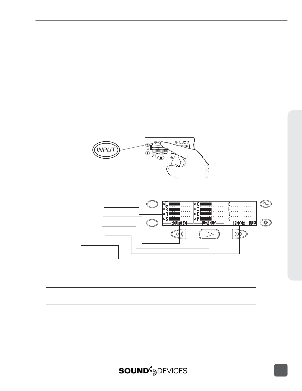
12. A TRACK MUST BE ARMED TO BE RECORDED.
Press the INPUT key to enter the Track Setup Window, where Tracks are enabled for recording. An * (asterisk) character next to a Track indicates that the
track is record enabled. Navigate through the Tracks using the Rotary Switch.
To enable/disable the track, press in on the Rotary Switch. Track Status is
indicated by the asterisk and by the blue Track Status LEDs on the 788T front
panel. When the LED and asterisk is solid the track is armed and will be recorded. A track becomes armed when it is enabled and has at least one active
(Switched on) Input routed to it.
When the asterisk and blue LED’s are fl ashing, the track is enabled but not
armed. Tracks that enabled but not armed will not be recorded!
788T
0
d
BFS
PWR
C
D
E
F
REC
0
d
BFS
INPUT
ARM ARM
R
L
A
B
EX
IN
CF
Track Setup Menu Basics:
Selector Box
Track Status Indicator
MENU
Input Routing Window
Master Levels Window
HDD
Track-to-Media Window
Meter Toggle
Meter Toggle selects the Tracks displayed on the Track Meter LEDs.
VU1 = Tracks C, D, E, F, G. VU2 = G, H, X1, X2. A-H = Tracks A, B, C, D, E, F, G, H
Quick Start Guide
Tip: After Inputs are routed to Tracks and the Tracks are enabled, simply click the Input Gain Pots on and
off to arm and disarm tracks respectively.
5
Page 14
A
R
788T/788T-SSD User Guide and Technical Information
13. HEADPHONE MONITOR.
Press the STOP key to return to the Main Display. Turn the Rotary Switch to
select the headphone preset best suited for the particular setup.
Active headphone routing. Track L in the left ear, Track R in the right ear.
14. Press the REC key to start recording.
Press the STOP key to stop the recording. Press the PLAY key to playback the
last recorded take.
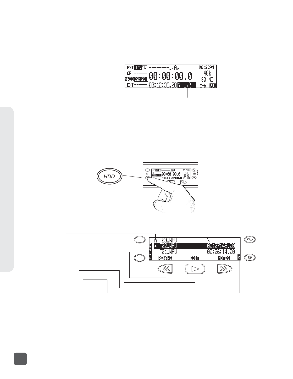
15.
Press the HDD key to enter the Take List.
The take list displays a listing of all recordings.
Quick Start Guide
Take List Basics:
Next Take
Selected Take (*= Last recorded Take)
Rename Take
Metadata Edit Menu
Add Take Notes
Exits the Take List
MENU
HDD
MENU
HDD
L
B
Turn the Rotary Switch to navigate through the Take List,
push to toggle the type of information displayed.
6
v. 3.02 Features and specifications are subject to change. Visit www.sounddevices.com for the latest documentation.
Page 15
788T/788T-SSD User Guide and Technical Information
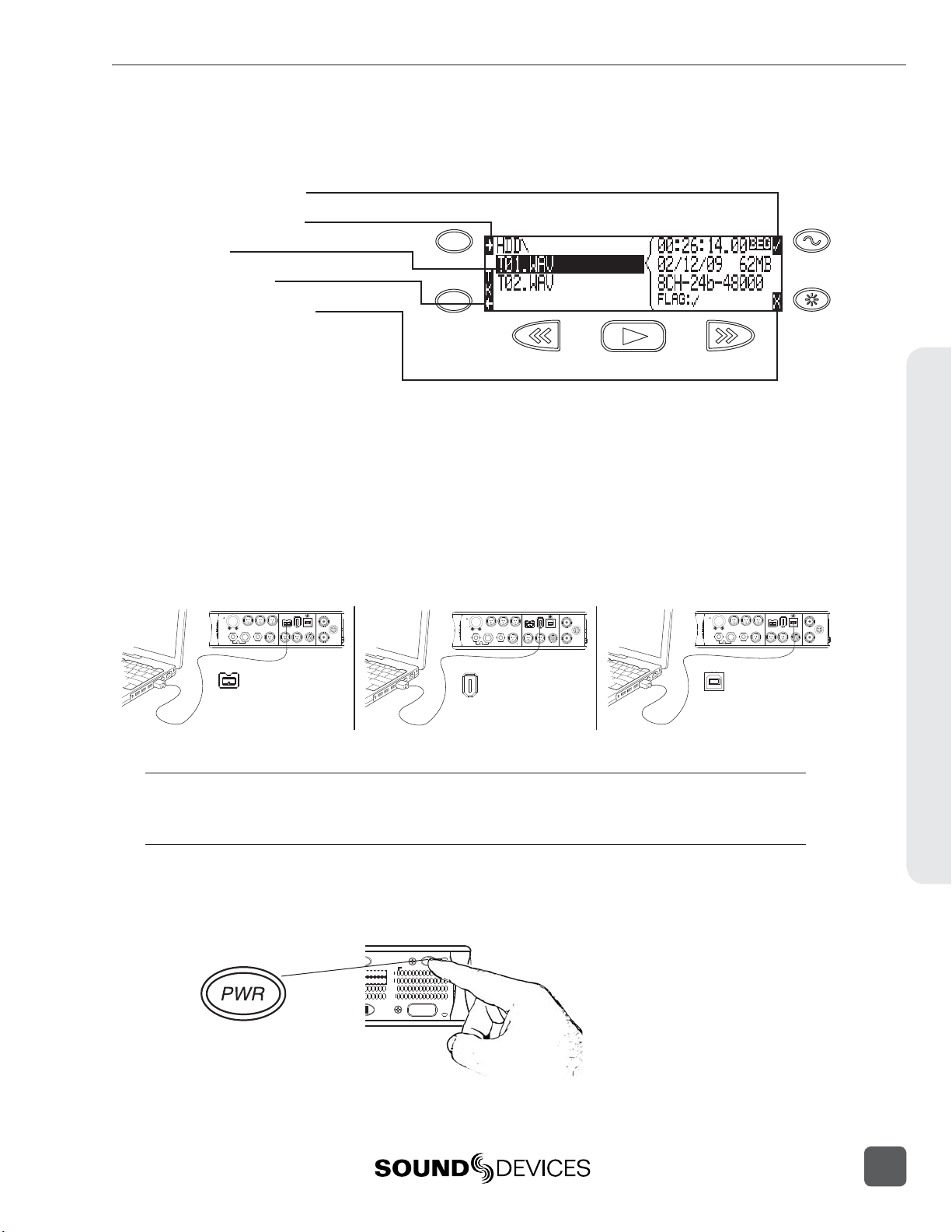
16. From the Take List, press the HDD key again to enter the Drive Direc-
tory.
Drive Directory Basics:
File Information Toggle
Jump to Root Directory
Selected File
MENU
Return to Take List
Exits the Drive Directory
HDD
Drive Formatting and other media-specifi c operations are accessed in the
Drive Options Menu located at the root directory.
17. After recording, transfer fi les from the 788T to a computer using ei-
ther FireWire 400, FireWire 800, or USB.
When connecting to a computer with a USB cable, make sure that the Setup
Menu option CONNECTION MODE is set to CONNEC T AS MASS S T ORAGE.
WORD/VID IN
DCIN
MENU
SELECT
1
23
FW800
ANALOGBALLINE OUTS
UNBAL
5,6
4
FW800
BALAES
OUT
1,2 3,4
10-18V
FW400
USB
SYNC
()
+
PIN4
()
-
PIN1
WORDOUT
TIMECODE
MENU
SELECT
1
23
ANALOGBALLINE OUTS
UNBAL
5,6
4
FireWire 400FireWire 800
FW400
WORD/VID IN
DCIN
BALAES
OUT
1,2 3,4
10-18V
FW400
USB
SYNC
()
+
PIN4
()
-
PIN1
WORDOUT
TIMECODE
FW800
MENU
SELECT
1
23
FW800
FW400
ANALOGBALLINE OUTS
UNBAL
USB
USB
USB
SYNC
BALAES
OUT
5,6
4
1,2 3,4
TIMECODE
To avoid any possible directory corruption on the 788T, do not interrupt the connection process. Always
properly dismount the drives from the operating system. On Mac OS platforms, drag the drive icons to
the trash. On Windows platforms, use the “Safely Remove Hardware” icon in the system tray.
18. Press and hold the PWR key for one second to shut down the record-
er.
788T
0
d
BFS
PWR
ARM
C
D
E
F
REC
0
d
BFS
T
WORD/VID IN
DCIN
10-18V
()
+
PIN4
()
-
PIN1
WORDOUT
Quick Start Guide
Front Panel Descriptions
All 788T settings can be accessed and monitored through the front panel LCD and navigation keys.
This allows the unit to be placed in a production bag along with other equipment.
7
Page 16
788T/788T-SSD User Guide and Technical Information
Panel and LCD Descriptions2
2
Panel and LCD Descriptions
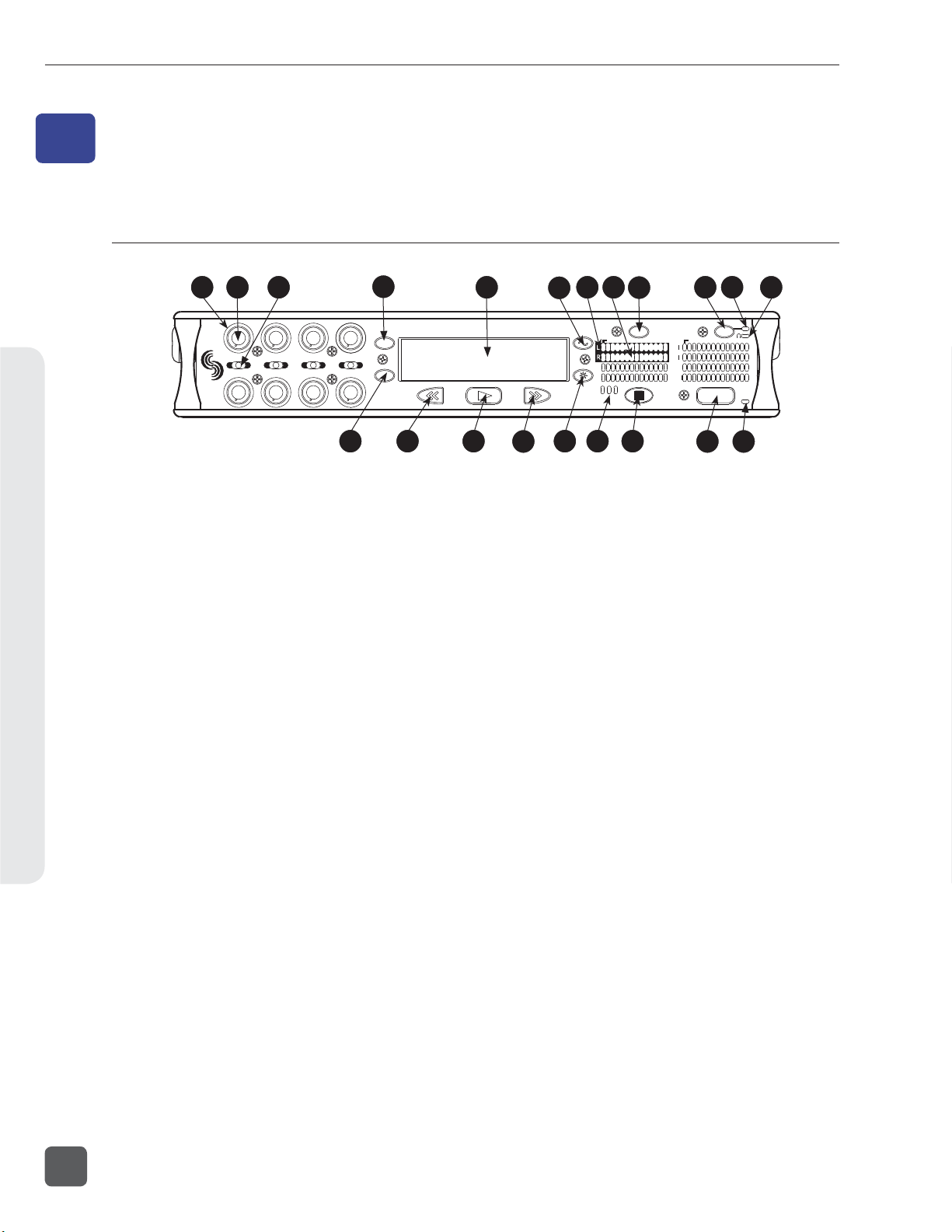
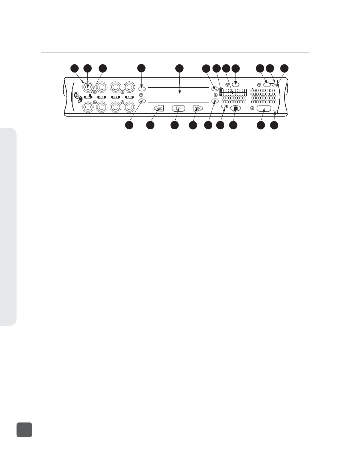
Front Panel Descriptions
1
2
3
3
1
2
5
4
6
1) Input Activity Ring LEDs
The LEDs surrounding each Input gain
pot indicate the input’s signal activity and
status.
See Metering and Display.
2) Input Gain Control
By default, controls the analog and digital
input gain (input trim) of each channel
respectively. The Input gain control can
be changed in the Setup Menu to act as
FADER CONTROLS. See Fader Control.
Can also be restricted to act as
INPUT ENABLES ONL Y where gain
adjustments are made from the Input Settings window. See Input Setup and Control
3) Input Selector/Solo Switch
Displays the Input Settings Screen for
the chosen Input. Setup Menu option
INPUT : P FL FUNCTION controls whether
or not the selected input will solo in the
headphones when the Input Settings Window is open. For momentary action, press
and hold the Input Selector in position for
one second or longer. See Input Setup and
Control
4) MENU Key
Accesses the 788T Setup Menu. When in
the Setup Menu use the MENU key to
move upward through the options and
parameters.
4
MENU
7
8
HDD
13 14 15
5
16
7 8
6
R
L
A
B
17 18 19
5) LCD Display
Primary display. Press and hold the LCD
Backlight key and press the Rotary Switch
to turn the LCD backlight on or off. Press
and hold the LCD Backlight key and turn
the Rotary Switch to adjust LCD backlight
brightness. By default the LCD backlight
color will indicate the recorder’s current
mode (confi gurable with Setup Menu option LCD: BACKLIGH T MODE). Red = Re-
cord, Green = Playback, White = Standby
6) TONE key
Press to activate the tone oscillator. Press
and hold for two seconds or longer to
latch on (Press again to deactivate). Press
and hold, then press LCD Backlight key
to toggle L-Ident tone mode. Frequency,
tone level, and routing are controlled in
the Setup Menu. When in the Setup Menu
use the TONE key to enter Setup Menu
options and select parameters when the
check mark appears in the upper right
hand corner of the LCD.
7) Track Status LEDs
A solid blue LED indicates that the respective track is armed (will be recorded).
A fl ashing blue LED indicates that the
Track is enabled but there is no active
input routed to it (will not be recorded).
The LED is off when the track is disabled.
9
INPUT
ARM ARM
EX
IN
CF
788T
0
d
BFS
C
D
E
F
11
10
PWR
REC
20 21
12
0
d
BFS
8
v. 3.02 Features and specifications are subject to change. Visit www.sounddevices.com for the latest documentation.
Page 17

788T/788T-SSD User Guide and Technical Information
8) Level Meter LEDs
Eight, 13-segment track level-meters indicate level in dBFS. Metering scale, ballistics, and peak hold times are selected in
the Setup Menu. Meters labeled C, D, E, F
can be used to view Tracks G, H, X1, X2.
See Metering and Display.
9) INPUT Key
Press to access the Track Setup Menu,
which provides access to enabling/
disabling and meter activity for all 12
Tracks. Press and hold the STOP key
and press the Input key to access the
INPUT : TRACK ROUTING Setup Menu.
Cycle through factory and custom routings by pressing the Input key while
holding the STOP key. See Input-to-Track
Routing
10) Power Key
To turn the 788T on or off, press and hold
the Power (PWR) Key for one second.
11) Power/Charge LED
Indicates the 788T is powered and available for operation. Also indicates the
charge status of the onboard battery
charger.
12) Headphone Output Peak LED
Indicates overload of the headphone amplifi er. When lit, the headphone circuit is
overloading. Reduce headphone level.
13) HDD Key
From the main screen, press the HDD
key to access the Take List (view and
edit metadata across all attached storage
media).
From the Take List, press the HDD key to
access the Drive Directory (navigate the
fi le system of all attached media, view
folder and fi le properties, and select fi les
for playback).
From the main screen, press and hold the
HDD key to toggle the playback source
between available media. In the Setup
Menu, use the HDD key to move down
through the options and parameters.
14) Rewind Key
Performs reverse (REW) scrubbing
through the played fi le when pressed
(and held) in playback and play-pause
mode. Reverse playback rate increases the
longer the key is held. In play-stop mode,
selects the previous fi le in the record
folder.
15) Play Key
Plays the fi le displayed in the LCD when
pressed in standby and play-pause mode.
Pauses playback when pressed in playback mode.
16) Fast-Forward Key
Performs fast-forward (FF) scrubbing
through the played fi le when pressed
(and held) in playback and play-pause
mode. Fast forward rate increases the
longer the key is held. In play-stop mode,
selects the next fi le in the record folder.
17) LCD Backlight Key
Press to toggle the Level Meter LEDs
View 1 (Tracks C - F) and View 2 (Tracks
G, H, X1, X2). Press and hold for 2 seconds to toggle between the select meter
scale and the favorite meter scale. See
Metering. Hold the Backlight key then
press the Rotary Switch to toggle the LCD
and Front Panel soft key backlighting on
and off. Hold the Backlight key and turn
the Rotary Switch to adjust the brightness of LEDs. In the Setup Menu the LCD
Backlight key functions as the cancel and
exit key.
Panel and LCD Descriptions2
9
Page 18
788T/788T-SSD User Guide and Technical Information
Front Panel Descriptions cont.
Panel and LCD Descriptions2
1
2
3
3
1
2
5
4
6
4
MENU
7
8
HDD
13 14 15
18) Media Activity LEDs
Indicates storage media activity. IN
(internal drive), CF (CompactFlash), EX
(external FireWire device). The LED illuminates green when the storage media is
ready, illuminates yellow when the storage media is writing/reading and while
connected to a computer, and illuminates
red when the storage media has encountered an error or if the drive has less than
one minute of recording time left.
Stop/Pause Key
19)
Momentarily press and hold this key to
stop recording. In playback mode, a single press pauses playback (play-pause),
allowing audio scrubbing with the FF
and REW keys. Another press of the key
enters play-stop mode where the FF and
REW keys select fi les for playback from
the current directory, the fi lename and
time display fl ash to indicate that a new
fi le has been selected. One more press of
the key exits playback mode.
Pressing the STOP key whilst in stop
mode displays the name of the next fi le
to be recorded in the LCD. In the Setup
Menu the STOP key is also used to exit
from any menu, returning to the main
display.
5
16
20)
7 8
6
ARM ARM
R
L
A
B
EX
IN
CF
17 18 19
Record Key
9
INPUT
788T
C
D
E
F
0
d
BFS
11
10
PWR
REC
20 21
12
0
d
BFS
Press to begin recording. The 788T is a
record-priority device; pressing this key
starts recording and discontinues all other
functions, except fi le operations. The REC
key will illuminate red when the 788T is
actively recording. If the selected storage
media is not ready to begin recording a
new fi le, the REC key will fl ash red until
the recording has begun. Pressing the
REC key during recording can set a cue
marker, start a new fi le, as selected in the
Setup Menu.
Record LED
21)
Illuminates red when record mode is active.
10
v. 3.02 Features and specifications are subject to change. Visit www.sounddevices.com for the latest documentation.
Page 19
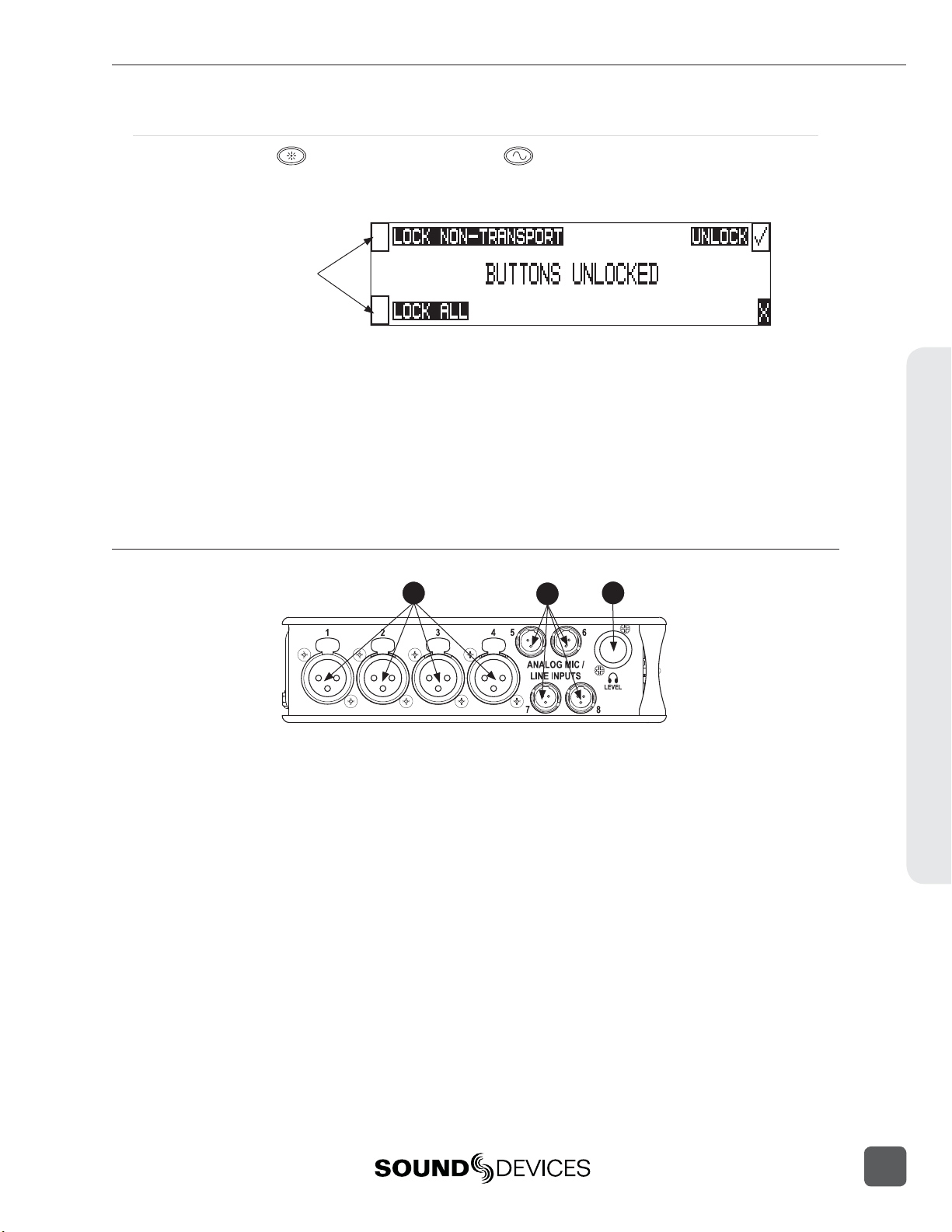
Panel Lock
788T/788T-SSD User Guide and Technical Information
Press and hold the LCD backlight key then the
ton Lock Screen. Button lock prevents unintentional setting changes and/or record status. The 788T
displays any button lock options currently enabled.
select the soft keys to
activate the appropriate
button lock mode
There are three modes:
• Unlocked – all keys are accessible and operate normally.
• Non-Transport Lock – All front panel controls are locked except the Record, Stop, Play, Rewind
and Fast Forward keys.
• Lock All – All front panel keys are locked except the REC key. The REC key is kept active so
the user can initiate recording after entering this mode and enter cue markers. To stop recording in this mode, you must disengage the panel lock and press the stop key.
TONE key to bring up the front panel But-
Left Panel Connectors and Controls
1
2
3
1) XLR Analog Inputs Channels 1-4
Active-balanced analog microphone- or
line-level input for inputs 1-4 on XLR connector. Input type is set within the Input
Settings Window. Pin-1 ground, pin-2 (+),
pin-3 ().
2) TA3 Analog Input Channels 5-8
Active-balanced analog microphone-orline-level input connector for inputs 5-8.
Input type is set within the Input Settings
Window. Pin-1 ground, pin-2 (+), pin-3
().
3) Headphone Volume
Adjusts the headphone volume. NOTE:
the 788T is capable of producing eardamaging levels in headphones. Please
use with caution
Panel and LCD Descriptions2
11
Page 20
788T/788T-SSD User Guide and Technical Information
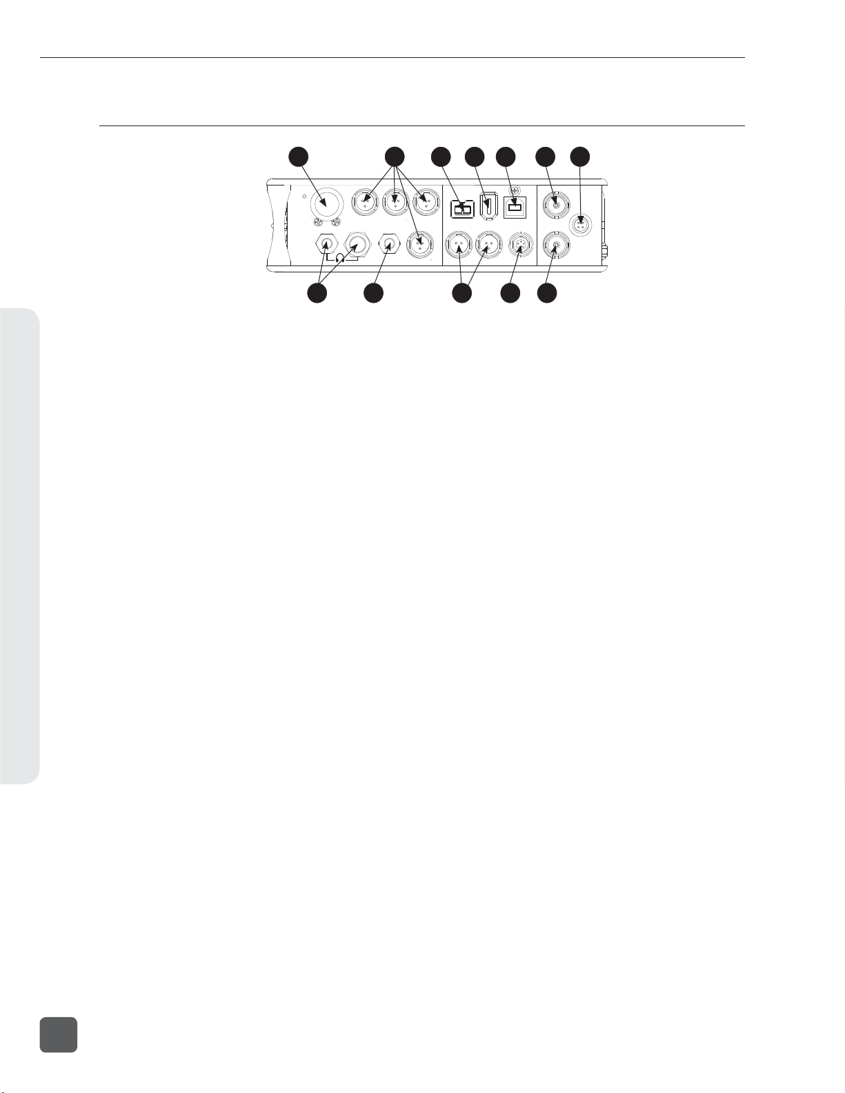
Right Panel Connectors and Controls
Panel and LCD Descriptions2
1
MENU
SELECT
8 9
1
1) Rotary Switch
When in the Setup Menu, the rotary
switch moves between menu selections;
push to enter selection or enter data.
In Record and Playback modes, selects
headphone monitor source; press action is
user selectable. Turn the knob while holding the LCD Backlight key to adjust the
brightness of LEDs.
2) TA3 Analog Outputs 1-4
Active-balanced, analog outputs 1-4.
Program source and attenuation levels are
user selectable. Pin-1 ground, pin-2 (+),
pin-3 (–). When connecting to an unbalanced input, do not connect pin-3.
3) FireWire 800 (IEEE-1394b) Port
Connection to a computer (Mac OS, Windows) to access the internal hard drive
and CompactFlash volumes as mass storage devices. Also used to attach external
FAT32-formatted FireWire drives to the
788T for direct recording and copying.
4) FireWire 400 (IEEE-1394a) Port
Connection to a computer (Mac OS, Windows) to access the internal hard drive
and CompactFlash volumes as mass storage devices. Also used to attach external
FAT32-formatted FireWire drives to the
788T for direct recording and copying.
5)
USB-B Port
Connection to a computer (Mac OS, Windows) to access the internal hard drive
and CompactFlash volumes as mass storage devices or for extended display and
control of the 788T using Wave Agent. See
Wave Agent for details.
2 7
ANALOG BAL LINE OUTS
UNBAL
5,6
3 4 5 6
23
FW800
BALAES
4
1,2 3,4
10 11 12
6)
FW400
USB
OUT
TIMECODE
Sync Input
SYNC
This BNC is used to connect an external
video sync or word clock reference signal
for word clock purposes. Accepts NTSC,
PAL, and Tri-level video syncs as well
as word clock rates between 32 kHz and
48.048 kHz.
7) External DC In
Accepts power from 10–18 volts DC to
power and charge the Li-ion battery.
Hirose 4-pin connector is wired pin-1
negative (-), pin-4 positive (+). Pin-2 and
pin-3 are not connected. Charging characteristics are set in the Setup Menu.
8) Headphone Output
1/4-inch and 3.5 mm TRS stereo headphone connectors. Can drive headphones
from 8 to 1000 ohm impedances to very
high levels. Tip = left, ring = right, sleeve
= ground.
9) Analog Output 5-6
Unbalanced output on 3.5 mm TRS stereo
connector. Program source and attenuation levels are user selectable. Tip = Ch5,
ring = Ch6, sleeve = ground.
10)
AES3 Output 1-2 and 3-4
Transformer-balanced AES3 digital outputs 1-2 and 3-4. Program source is user
selectable.
11) Time Code Multi-Pin
Time code input and output on 5-pin
LEMO® connector.
12) Word Clock Output
Provides a word clock output running at
the sample rate of the 788T.
WORD /VID IN
DC IN
10-18V
PIN 4
PIN 1
WORD OUT
()
+
-
()
12
v. 3.02 Features and specifications are subject to change. Visit www.sounddevices.com for the latest documentation.
Page 21
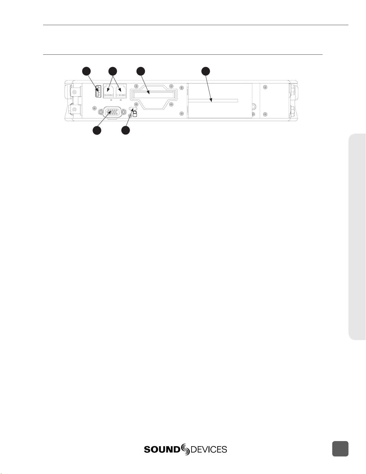
Rear Panel Descriptions
788T/788T-SSD User Guide and Technical Information
1
KEYBD
OUT
AES I/O, GPIO, PWR
5
3 42
INC.LINK
COMPACTFLASH
6
1) USB Keyboard Input
USB A Female Connector for USB keyboard and CL-8 Controller See Remote
Control for more details regarding Keyboard
and CL-8 setup and functionality.
2) C. Link In/Out
RS-232 protocol interface on 6-pin modular (“RJ-12”) connector for linking multiple 7-Series recorders together. Word
clock, machine transport, and time code
are carried on the C. Link connector. See
Multi Unit Linking Via C. Link. Also used
for connection to CL-WIFI Wireless,
Interface, CL-1 Keyboard and Remote
Control Interface, or CL-2 Remote Fader.
See Remote Control for more details. The
C. Link In is disabled when Setup Menu
option FireWire/USB: Connection is set to
connect to Wave Agent.
Multi-Function DE-15 Connector
5)
Mates with Sound Devices XL-88 MultiPin Breakout Cable. The DE-15 connector
acts as AES3 Inputs 1-8, AES3 Outputs
5-6, and Logic In and Out. Analog and
digital inputs can be used simultaneously.
See Connector Pin Assignments.
Sample Rate Converters are enabled
on each AES input when Setup Menu
REC: S YN C SO URCE is set to Internal. See
Sample Rate Converters.
AES inputs support AES42 Mode 1 operation, supplies +10 V of digital phantom
power. See AES42 Digital Microphones.
6) Security Slot
Compatible with the Kensington® Security Slot specifi cation. Used to secure the
recorder to a fi xed object with a compatible computer lock.
3)
CompactFlash Slot
Accepts CompactFlash cards, label-side
up. Compatible with Type I, Type II, and
MicroDrives. High-speed UDMA cards
are recommended for higher track count
recording.
4) Battery Mount
Accepts Sony® InfoLithium L-Series batteries. Also accepts batteries conforming
to this mount. Numerous capacities, from
1500 to 7000 mAh are available.
Panel and LCD Descriptions2
13
Page 22
788T/788T-SSD User Guide and Technical Information
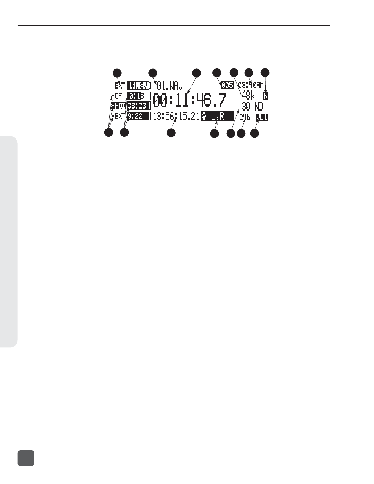
LCD Display Descriptions
Panel and LCD Descriptions2
1
8
9
1) Battery/Voltage Level Indicator
Indicates voltage level of the removable
battery or external power sources. If
present, external power overrides battery
power. Graphical bar for relative level
and numeric indicator for precise voltage
measurement.
File Name Display
2)
Shows fi le name actively being recorded
or played back. In Playback-Stop mode,
fl ashing fi le name indicates that the FastForward and Rewind keys can be used to
step through fi les in the current playback
directory.
3) Absolute Time (A-time) Display
Shows the elapsed time of the fi le being
recorded or played back in hours, minutes, seconds, and tenths. The A-time and
the time code display can be exchanged if
a large time code display is needed. This
display can be set to reverse or fl ash while
recording. Flashes in playback-pause
mode.
4) Cue Marker Display
In Record mode, indicates when cue
markers are set. Markers set by pressing
the REC key (option must be selected in
Setup Menu). In Playback mode, displays cue points numerically as they are
reached in a fi le.
5) Sample Rate Indicator
Displays the set record sampling rate. In
Playback mode, displays the currently
selected fi le’s sampling rate.
2
3
10
4
12 13
11
6) Time & Date Display
Alternating display between the set date
and time of the 788T. This information is
written as the creation and modifi cation
date for generated audio fi les.
External Digital Clock Indicator
7)
This display will show when the 788T
is locked to a valid external sync source,
sync reference is user-selectable in the
Setup Menu. The display will indicate the
current valid sync source
D = digital input, W = word clock, V =
video. The display currently shows that
the recorder is successfully locked to a
valid word clock source.
8) Media Descriptors
For all three media types, an asterisk in
front of the media descriptor indicates
which media is selected for record. Highlighted media descriptor indicates media
selected for record monitoring, playback
or fi le directory display.
9) Media Status
6 75
14
(space remaining/record ready)
Bar graph indicates the remaining record
time available on the select media. Numbers show time in hours and minutes
based on the presently selected number
of record tracks, sample frequency, and
bit rate. Display toggles between remaining time and track count when media is
set to receive less than the full amount of
armed tracks. See Track-to-Media Routing.
Indicator shows dashes when no media
is available or if there is no armed tracks
routed to it.
14
v. 3.02 Features and specifications are subject to change. Visit www.sounddevices.com for the latest documentation.
Page 23
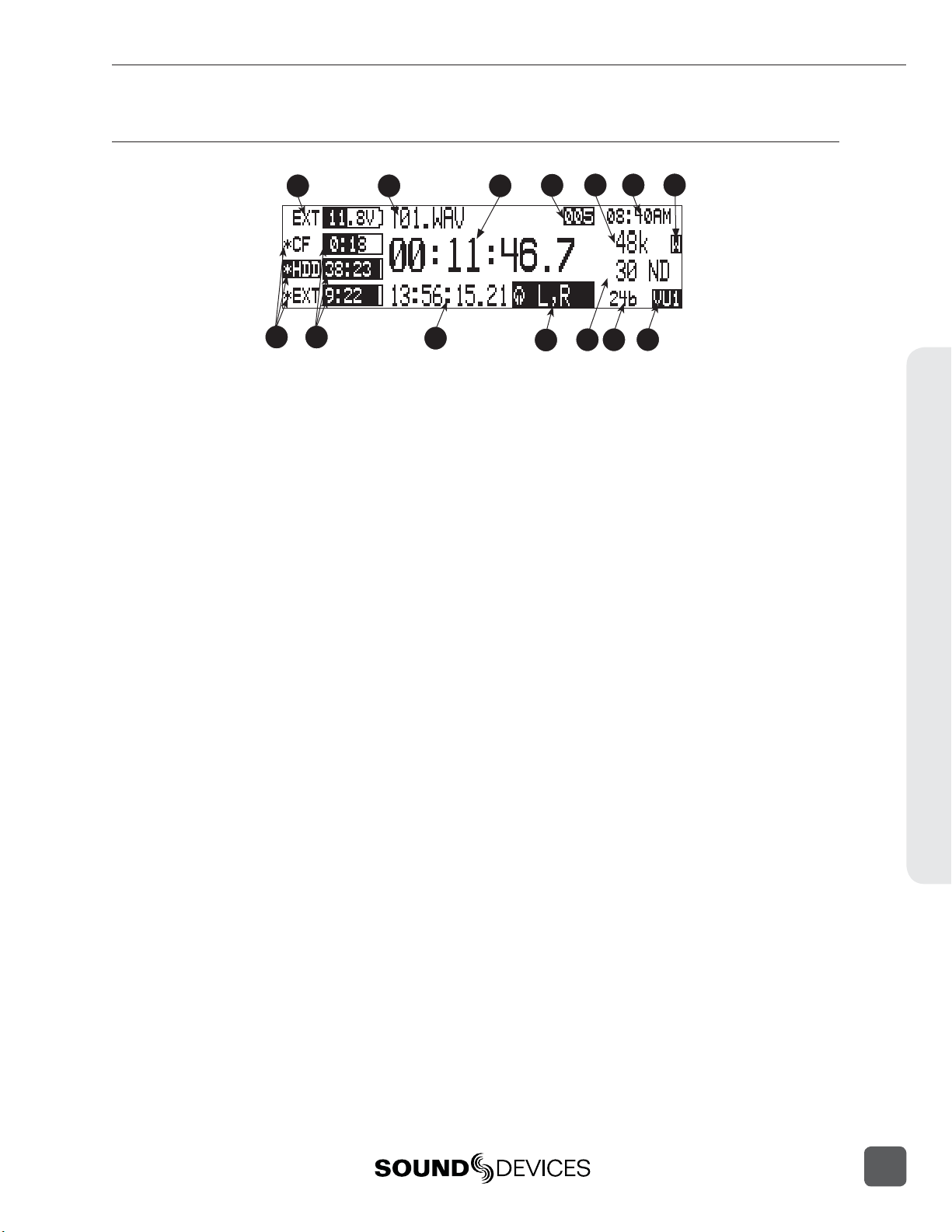
LCD Display Descriptions cont.
788T/788T-SSD User Guide and Technical Information
1
8
9
10) Time Code Display
In Stop and Record modes, displays the
time code generated or received by the
788T. In Playback mode, displays the the
time code information of the fi le currently
selected for playback (if available). If nontime code fi les are playing, the display
shows dashes. The time code display can
be exchanged with the A-time display in
the Setup Menu.
Headphone Source Display
11)
Indicates the source for headphone output. Sources and selection order are user
selectable in the Setup Menu.
12) Time Code Frame Rate
Displays the set time code frame rate. If
a fi le has time code information embedded, the playback frame rate is indicated.
If external time code is connected and
the external rate differs from the rate set
internally, the display will fl ash.
2
3
10
4
12 13
11
13) Bit Depth Indicator
Shows the set record bit depth. In playback, shows the fi le bit depth.
Meter Toggle
14)
Press the soft VU (LCD Backlight) key
to toggle between VU1, VU2, and A-H
views. VU1 displays Tracks L, R, A, B, C,
D, E, F on the Meter LEDs. VU2 displays
Tracks L, R, A, B, G, H, X1, X2. A-H displays Tracks A, B, C, D, E, F, G, H on the
Meter LEDs.
Press and hold the LCD Backlight key
for two seconds to toggle between the selected meter scale and the favorite meter
scale. FAV and the selected VU view will
alternate when favorite meter mode is
active.
6 75
14
Panel and LCD Descriptions2
15
Page 24
788T/788T-SSD User Guide and Technical Information
Panel and LCD Descriptions2
15
16
17
18
15) Input Level
When input gain is adjusted, gain level
is indicated in dB for the input being
adjusted and its neighboring input. The
relationship of inputs is confi gured in the
following manner and cannot be altered
1,2 / 3,4 / 5,6 / 7,8. Neighboring inputs
are not linked or grouped unless specifi cally linked in the Setup Menu. Mic input
gain range is from 0 dB to 76 dB, Line input range is from -25 to 50 dB and Digital
input range is from -25 to 50 dB.
16) Headphone Gain Level
When the headphone gain is adjusted,
this will appear and indicate the gain
level in dB.
17) Slate Mic Gain Level (CL-8 only)
Slate Mic gain level is adjusted from -46
to 6 dB in 1 dB increments. To attenuate
the gain press and hold the CL-8 SLATE
button and turn the Rotary Switch.
18) Media Track Count
Display toggles between remaining time
and track count when media is set to
receive less than the full amount of armed
tracks. See Track-to-Media Routing.
16
v. 3.02 Features and specifications are subject to change. Visit www.sounddevices.com for the latest documentation.
Page 25
788T/788T-SSD User Guide and Technical Information
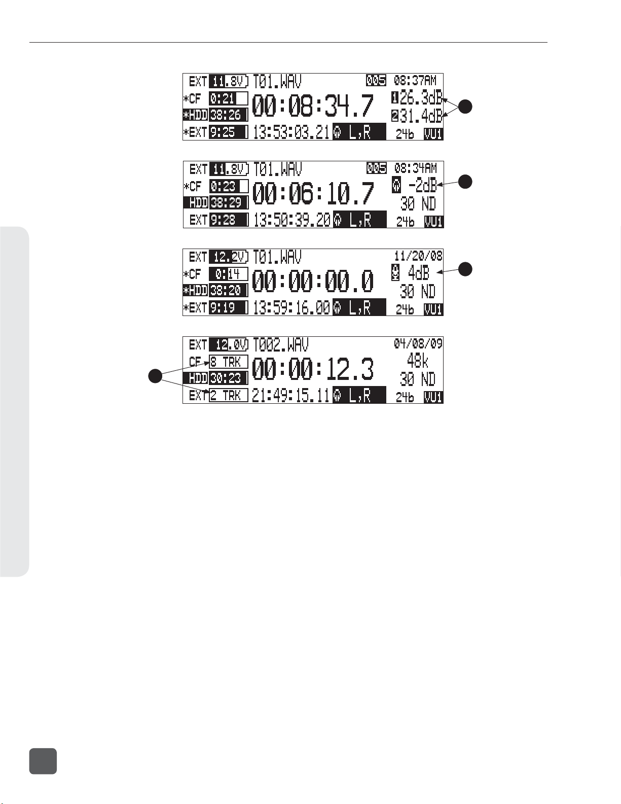
Input Settings Window Descriptions
To access the Input Settings Window press the Input Selector Switch into the position of the desired
input. Pushing the Input Selector Switch to the left will select the odd numbered inputs and pushing it to the right will select the even numbered inputs. Press the Input Selector Switch for the select
input again to return to the previously displayed screen.
1
7
11
1) Input Type
The highlighted selection indicates current Input Type. Input Type is selectable
from Mic, Line, and Digital Inputs for
each channel respectively. Toggle through
Input Type selections by pressing the
MENU key.
2) Input Gain Display
The Input gain is displayed in dB for
the selected input. Information displayed toggles between TRIM and
FADER levels when faders are available. When the Setup Menu option
INPUT: FRONT PANEL CONTROLS is set
to Fader Controls, use the Rotary Switch
to attenuate Trim levels. Pressing in on
the Rotary Switch will toggle control
between Trim level and High-Pass Filter
control.
3) Input Selected
Displays the Input that has been selected.
4) Headphone Monitor Hold Indication
Press and hold the Input Selector
Switch for fi ve or more seconds to latch
Input PFL. To exit the PFL monitoring select another input with the Input
Selector Switch or rotate the Rotary
Switch. This mode only applies when
the INPUT: PFL FUNCTION is set to
enabled.
2
4 653
8
5) High-Pass Filter
Indicates the state of the High-Pass
Filter and the cut off frequency selected.
Control the High-Pass Filter by using the
Rotary Switch.
6) Phantom Power
The highlighted selection shows the current state of phantom power (48V: mic
only, 48VL: mic and line, Off: no phantom
power) for the selected input. Switch
between Phantom Power modes by using
the Tone key.
7) Input Limiter
The highlighted selection shows the state
of the Input Limiter for the selected Input.
Enable or disable the Input Limiter using
the HDD key.
8) Input to Track Routing
The highlighted selection(s) indicate the
track(s) the selected input is currently
routed to. To enter and exit the Input to
Track Routing press the Play key.
9) Input Mute
When highlighted the selected Input is
Muted and removed from all tracks. Input
Mute is toggled on and off using the Fast
Forward key.
10)
Input Polarity
When highlighted the Input Polarity is
inverted. Control polarity using the LCD
Backlight key.
9
10
Panel and LCD Descriptions2
17
Page 26
788T/788T-SSD User Guide and Technical Information
11) Mix Assist
The highlighted selection shows
whether or not the input is automixed.
This option will be crossed out when
MIXASSI ST: MODE is set to Off. Automix
is toggled on and off using the Rewind
key. See Mix Assist
The following screen appears if the select Input is linked as a stereo pair.
12
Panel and LCD Descriptions2
The following screen appears if the select Input gain pot is switched to the Off position.
13
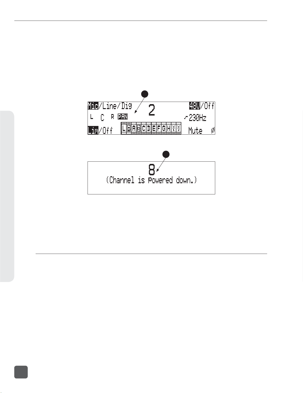
12) Panning Control
If the Input selected is a linked stereo pair,
the odd numbered inputs will display
gain and the even numbered inputs will
display the stereo image.
13) Channel Is Powered Down
The Input Settings Window cannot be accessed if the Input’s Gain Pot is switched
to Off.
Track Setup Window
The Track Setup Window allows a user to record enable or disable tracks, route inputs-to-tracks,
adjust master gain levels, and route tracks-to-media. Press the front panel INPUT key to access the
Track Setup Window. There are four views of the Track Setup Window, Track Level Meters View,
Track Routing View, Master Gain Levels View, and Media-to-Track View. The Track Meters View is
always the fi rst view to appear upon entry of the Track Setup Window. Items that appear in all views
have identical functionality.
18
v. 3.02 Features and specifications are subject to change. Visit www.sounddevices.com for the latest documentation.
Page 27
Track Level Meters View
1 2
788T/788T-SSD User Guide and Technical Information
3
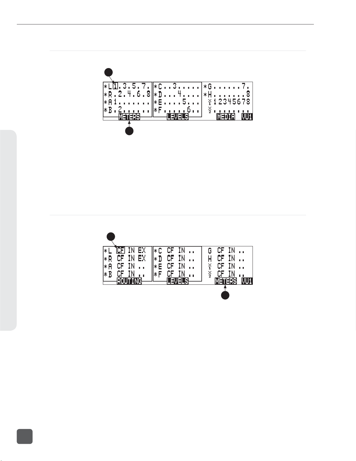
1) Track Status Indicator
An * (asterisk) next to a Track indicates
that the track is record enabled. Navigate through the Tracks using the Rotary
Switch. The selected track has a box
around it (Track G in the example above).
To enable/disable the track, press in on
the Rotary Switch. Track Status is indicated by the asterisk and the 788T Front
Panel Track Status LEDs. When the LED
and asterisk is solid the track is armed
and will be recorded, when it fl ashes the
track is enabled but no active input is
routed to it and will not be recorded, the
asterisk and LED remain off when the
track is disabled.
2) Track Level Meters
Displays all twelve available track Level
Meters. Meter ballistics settings are identical to the front panel Track Level Meters
and are adjustable within the Setup
Menu.
4
3) Track Routing View
Press the Rewind key to access the Track
Routing View.
4) Master Gain Levels View
Press the Play key to access the Master
Levels View.
5) Track-to-Media View
Press the Fast Forward key to access the
Track-to-Media view.
6) Meter Toggle
Press the soft VU (LCD Backlight) key
to toggle between VU1, VU2, and A-H
Meter views. VU1 displays Tracks L, R,
A, B, C, D, E, F on the Meter LEDs. VU2
displays Tracks L, R, A, B, G, H, X1, X2 on
the Meter LEDs. A-H displays Tracks A,
B, C, D, E, F, G, H on the Meter LEDs.
5
6
Panel and LCD Descriptions2
19
Page 28
788T/788T-SSD User Guide and Technical Information
Track Routing View
The screen below is the Track Routing View, it appears if the ROUTING (Rewind) Key is selected.
7
8
Panel and LCD Descriptions2
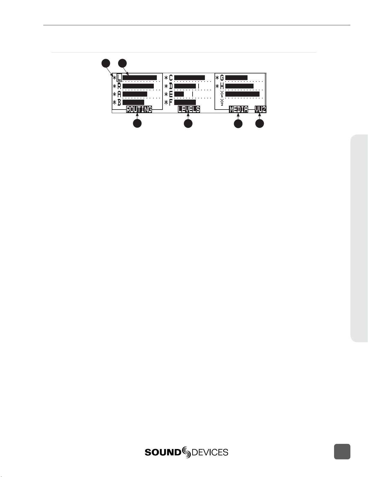
7) Track Routing
Displays all inputs currently routed to the
given track. Rotate the Rotary Switch to
move the selector box. Press in on the Rotary Switch to route an Input to the Track.
Pre- or post-fade routing is applied as it is
defi ned in the Input Settings Window or
the Setup Menu.
Track-to-Media View
The screen below is the Track-to-Media View, it appears if the MEDIA (Fast Forward) Key is selected.
9
9) Track-to-Media Routing
Displays which media the given track will
be recorded to. Rotate the Rotary Switch
to move the selector box. Press in on the
Rotary Switch to toggle the routing of the
track to CompactFlash, Internal Drive, or
External media respectively. Tracks will
only be written to a given media if it is
selected in the Setup Menu option Rec:
Media Select, regardless of it’s Track-toMedia routing status.
8) Track Level Meters View
Press the Rewind key to return to the
Track Level Meters Window.
10
10) Track Level Meters View
Press the Rewind key to return to the
Track Level Meters Window.
20
v. 3.02 Features and specifications are subject to change. Visit www.sounddevices.com for the latest documentation.
Page 29
Master Gain Levels View
The screen below is the Master Gain Levels View, it appears if the LEVELS (Play) Key is selected.
788T/788T-SSD User Guide and Technical Information
11 12 13
1615 18
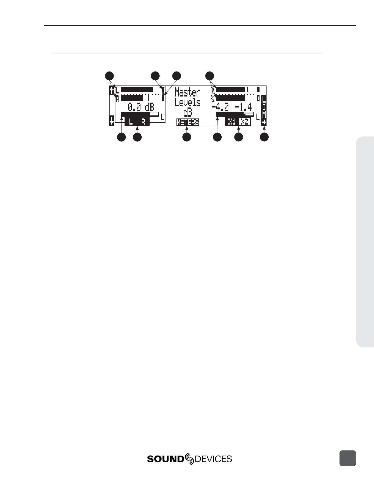
11) L/R Meters
Displays real time metering of Left and
Right Track Levels.
12) Track Limiter Indicator
Appears when Track Limiter is engaged.
Limiter is active when the indicator is
solid.
13) Track Limiter Linked
Indicates that the track limiter is linked.
14) AUX Meters
Displays real time metering of X1 and X2
Track Levels.
15) L/R Master Gain Level
Displays gain level applied to the Master
Left and Right Tracks. Only one bar is displayed when tracks are linked as a stereo
pair (as shown). Two bars are displayed
when the tracks are independent.
16) L/R Master Gain
Pressing the soft L/R (Rewind) key will
select the Left and Right Tracks Master
Gain level. Pressing again will select the
track to be controlled. When both tracks
of the pair are highlighted the Tracks are
linked as a stereo pair (as shown). Gain
is adjusted from -60 to +15 dB in .1 dB
increments using the Rotary Switch or the
soft up and down arrows. Press in on the
Rotary Switch to return to unity gain (0
dB).
14
17
17) Meters
Press the soft METERS (Play) key to return to the Track Level Meters View.
18) AUX Master Gain Level
Displays gain level applied to the Aux
Tracks. Only one bar is displayed when
tracks are linked as a stereo pair. Two bars
are displayed when the tracks are independent (as shown).
19) AUX Master Gain
Pressing the soft AUX (Fast Forward) key
will select the Aux Tracks Master Gain
level. Pressing again will select the track
to be controlled. When both tracks of the
pair are highlighted the Tracks are linked
as a stereo pair. Gain is adjusted from -60
to +15 dB in .1 dB increments using the
Rotary Switch or the soft up and down
arrows. Press in on the Rotary Switch to
return to unity gain (0 dB).
20) Limiter Key
Press the LCD Backlight key to toggle the
select stereo pairs Track Limiter status.
Each press cycles the various settings Off,
On, Linked. See Track Limiters for details.
19 20
Panel and LCD Descriptions2
21
Page 30
788T/788T-SSD User Guide and Technical Information
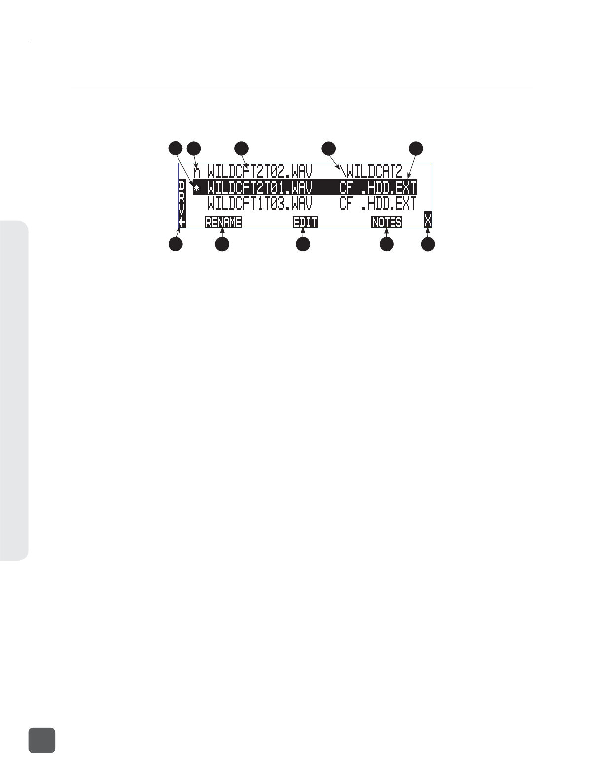
Take List Descriptions
To access the Take List press the HDD key or select Setup Menu option FILE: VIEW TAKE LIST.
From the Take List view and edit metadata across all storage mediums.
Panel and LCD Descriptions2
1
2
6
1) Current/Last Take
The * (asterisk) indicates the current take
being recorded or the last take to have
been recorded by the 788T.
2) Next Take
The n indicates the name of the next take
to be recorded. With the n take highlighted the user can make notes entry or
increment/decrement Scene and Take for
the next fi le to be recorded.
3) Take Name Column
This is a sequential list of Takes recorded
by the 788T fi rmware revision 1.5+.
4) Next File Destination
Displays folder destination for the next
Take to be recorded.
5) Additional File Information
Displays additional fi le information, the
following information can be toggled
through by pressing in on the Rotary
Switch: Beginning Time Code Stamp,
Time of File Creation, Date of File Creation, Scene Names, Drives Containing
the File, and Folder that Contains the File.
3
7
4
6) DRV (Drive Directory)
Press the soft Drive (HDD) key to access
the Drive Directory (File Viewer).
7) RENAME
Press the soft RENAME (Rewind) key to
access the fi le/metadata rename window.
8) EDIT
Press the soft EDIT (Play) key to access
the Take Edit Menu. From this menu,
make notes entries and view/edit the following metadata at anytime for any take:
Notes, Rename, Circle, Project, Scene,
Take, Tape (Roll), Set/Clear Copy, Delete
(sends fi le to the Trash), and Rename
Tracks.
9) NOTES
Press the soft NOTES (Fast Forward) key
to quickly access the Notes fi eld.
10) X Exit
Exits to the previously viewed window.
5
98
10
22
v. 3.02 Features and specifications are subject to change. Visit www.sounddevices.com for the latest documentation.
Page 31

788T/788T-SSD User Guide and Technical Information
The following screen appears if the next (n) fi le is highlighted.
11
11) Take +/-
Appears when the next take, indicated by
the “n” is highlighted. Pressing the soft
Take +/- (Rewind) key will access the
Take increment or decrement options.
The following screen appears if Take +/- (11) is selected.
13
14
13) Take -
Appears when the Take +/- is selected.
Pressing the Take - (Rewind) key will
decrement the take number. If the take
number is decremented to match the
name of the last fi le recorded, the False
Take prompt will appear.
12
12) Scene +/-
Appears when the next take, indicated by
the “n” is highlighted. Pressing the soft
Scene +/- (Fast Forward) key will enter
the Scene increment or decrement window.
15
14) Done
Pressing the soft DONE (PLAY) key saves
the increment/decrement settings for the
next take to be recorded.
15) Take +
Appears when the Take +/- is selected.
Pressing the soft Take + (Fast Forward)
key will increment the take number.
Panel and LCD Descriptions2
The following screen appears if Scene +/- (12) is selected.
16
14
17
23
Page 32

788T/788T-SSD User Guide and Technical Information
Panel and LCD Descriptions2
16) Scene -
Appears when the Scene +/- is selected in
the above window. Pressing the Scene (Rewind) key will decrement the scene.
17) Scene +
Appears when the Scene +/- is selected.
Pressing the soft Scene + (Fast Forward)
key will increment the scene. Scenes
will be incremented with either alpha
characters or numeric digits, depending on the setting for Setup Menu option
REC : S CENE INCREMENT MODE.
Drive Directory (File Viewer) Descriptions
To access the Drive Directory press the soft DRV (HDD) key from within the Take List. Press the
HDD key twice from the main screen for quick access to the Drive Directory. To return to the Take
List from the Drive Directory, press the TK soft (HDD) key.
1
2
3
5 7
4
6
8
1) Root Directory
Press to quickly access the Root Directory.
From the Root Directory, navigate between media or perform drive functions
via the Drive Options Menu.
2) Directory Path
Indicates the directory path for the fi le/
folder currently being viewed.
3) Selected File
Scroll through polyphonic and monophonic fi les using the Rotary Switch. The
highlighted fi le will display fi le properties
and additional fi le information. Press play
to immediately playback the select fi le.
4) Additional File Information
Displays additional information of the
currently selected fi le. The information
displayed is determined by the state of
the File Information Toggle (6).
Time and Date
5)
Display toggles between date of fi le
creation and time of fi le creation for the
highlighted fi le.
9
10
6) File Information Toggle
Press to toggle the type of information
displayed in the Additional File Information fi eld (4). The following information is
displayed.
BEG = Beginning Time Code Stamp, LEN
= Length of File, USR = User Bits, FPS =
Frames Per Second.
7) File Size
Displays the size of the currently selected
fi le.
8)
Take List
Press to access the Take List.
9) File Properties
Displays channel count, bit depth, and
sampling rate of the highlighted fi le.
Copy Flag Status
10)
Displays the status of the Copy Flags.
Check marked fi les have Copy Flag set.
11) X Exit
Exits to the main screen.
11
24
v. 3.02 Features and specifications are subject to change. Visit www.sounddevices.com for the latest documentation.
Page 33

788T/788T-SSD User Guide and Technical Information
Root Directory
The following screen appears if the Root Directory (1) is selected.
12
12) Media Select
Highlight desired media to view or perform drive functions.
13) Free Space
Displays the amount of free space available on the highlighted media. The time
available is dependent on user setup.
14) Media Size
Displays the media size for the highlighted media.
15) Drive Directory Options Menu
Press the soft Options (Fast Forward) key
to access the Drive Options Menu. The
following drive functions are performed
in the Drive Options Menu: Rename, Set/
Clear Copy Flags, Empty Trash and False
Takes, Erase (format).
13
14 15
25
Panel and LCD Descriptions2
Page 34

788T/788T-SSD User Guide and Technical Information
Inputs and Outputs3
3
Inputs and Outputs
Input Setup and Control
The 788T has eight inputs and twelve record tracks. Inputs can be analog or digital sources. Analog
inputs 1 through 4 are on 3-pin XLR connectors; inputs 5 through 8 are on 3-pin TA3 connectors.
Digital AES3 inputs 1-8 use the DE-15 (D-Sub) connector.
Analog and digital inputs can be used simultaneously, for a total of eight.
Input Trim and Input Faders
The Front Panel Input Gain Controls can be switched to the Off position to disable and power down
the input and to ultimately extend battery life. Disable inactive inputs by turning the Input Gain
Control to the full counter-clockwise (Off) position. The Input Gain Controls must be on to route an
input to a track and/or access the Input Settings Window.
The gain of an input is adjusted by two controls, its Input Trim and its Input Fader. This two-stage
control is identical the to topology of mixing consoles and provides a great deal of fl exibility when
inputs are assigned to tracks. Input Trim is often thought of as a coarse gain control and Input Fader
is thought of as the fi ne gain control.
From the factory, the front panel Input Gain Controls adjust trim levels. When an input is sent to
a track, the input is sent at the level controlled by the Input Trim. In this factory default mode, the
Input Fader control is set at unity, cannot be controlled, and has no effect on levels.
The Setup Menu option INPUT: FRONT PANEL CONTROLS provides three options, Trim Control,
Fader Control, or Input Enables Only. This menu is not available when the CL-9 is attached. Selecting Fader Control changes the eight front panel Input Gain Controls to adjust the fader level on
an input. Trim levels are now set using the Rotary Switch from within the respective input’s Input
Settings Window. Pressing in on the Rotary Switch will toggle between Trim control and High-Pass
Filter control. When Input Enables Only is selected, the Front Panel Controls turn the inputs on and
off only and the Trim Level is controlled within the Input Settings Window.
When Input: Front Panel Controls is set to anything other than Trim Controls, panning linked inputs is
disabled.
The fader range is adjustable in the Setup Menu option INPUT: FADER RANGE between Wide, Fade
Only, and Narrow. A Wide range allows the user to attenuate the fader from negative infi nity (off) to
+15 dB. Fade Only allows the user to attenuate the fader level from negative infi nity (off) to 0 dB. A
narrow range allows the user to attenuate the fader level from -15 to +15 dB. Fader levels are relative to the trim level of the selected input. Fader range applies to all available faders including, Front
Panel Gain Controls (if set as Fader controls in the Setup Menu option Input: Front Panel Controls),
the CL-2 fader, the CL-8, and the CL-9 faders.
The CL-8 and CL-9 faders can be calibrated in the Setup Menu option FADER CAL. This allows the
Sound Mixer to set the 0 dB (unity gain) position of the fader. To calibrate the faders of the CL-8 or
CL-9, set all fader levels to the desired 0 dB position. Enter the Setup Menu option FADER CAL and
press the check mark.
26
v. 3.02 Features and specifications are subject to change. Visit www.sounddevices.com for the latest documentation.
Page 35

788T/788T-SSD User Guide and Technical Information
When the CL-9 is attached to the 788T, the trim and fader levels are adjusted only from the CL-9. The
788T Front Panel Gain Controls simply activating/deactivating inputs.
When the CL-8 is attached to the 788T and the Setup Menu option INPUT: FRONT PANEL CONTROLS
is set to Trim Controls or Fader Controls, the behavior of the front panel Input Gain Control adjusts
trim levels and the CL-8 rotary potentiometer controls the Input Fader level. When Setup Menu option INPUT: FRONT PANEL CONTROLS is set to Input Enables Only, the behavior of the front panel
Input Gain Control simply activates/deactivates the input, trim levels are adjusted in the Input Settings Window using the Rotary Encoder, and the CL-8 rotary potentiometer controls the Input Fader
level. When the CL-8 is attached, the Fader Controls option has no effect. The front panel controls
continue to act as trims and the CL-8 faders act as input fader controls.
When the CL-2 is attached and assigned to an input, the input’s fader level will be controlled by the
CL-2 only.
Input Settings Window
From the Input Settings Window, view and/or change the following settings:
• Input Type
• Phantom Power
• High-Pass Filter
• Input Gain (Trim and Fader)
• Input Limiter
• Input Polarity
• Input Mute
• Input Routing
• Mix Assist
To enter the Input Settings Window, press the desired input’s Front Panel Input Selector Switch. The
Input Settings Window will latch on, this allows for one handed operation of the 788T. If momentary
action is desired, press and hold the Input Selector Switch for one second or more. To exit the Input
Settings Window press the selected Input Selector Switch again or select another Input.
While in the Input Settings Window the selected input is displayed in the center of the screen. The
selected input will be soloed in the headphone monitor, although this can be disabled in the Setup
Menu option INPUT : P FL FUNCTION.
If the Input Selector/Solo Switch is held for 5 or more seconds “Hold” will appear on the screen
and the soloed input will remain in the headphone monitor until either another headphone monitor mode has been selected with the Rotary Switch or with the Input Selector/Solo Switch. Once the
Input Selector Switch is pressed again, the 788T will return to the previously displayed screen.
If the selected input is stereo linked, both of the inputs will be soloed in the headphone monitor.
Inputs and Outputs3
27
Page 36

788T/788T-SSD User Guide and Technical Information
Input Type
Select between Mic, Line, or Digital inputs using the MENU key while in the Input Settings Window.
Input Type Input Connectors Gain Range (Trim only)
Mic XLR 1-4, TA3 5-8 Off (-infinity) 0 dB to 76 dB
Line XLR 1-4, TA3 5-8 Off (-infinity) -25 dB to 50 dB
Digital AES3 1-8 (D-Sub 15) Off (-infinity) -25 dB to 76 dB.
Phantom Power
Phantom power (48 volts) can be activated individually, for each analog input on. Phantom power
can be used for both mic- and line-level inputs. Enable or disable Phantom Power in the Input Settings Window using the Tone key to select 48V (phantom power for mic level only), 48VL (phantom
power for mic- and line-level), or Off.
Using line-level inputs with microphones is useful in high SPL environments such as recording fi rearms
or loud concerts. Make certain to disable phantom power on inputs with attachedc line-level output devices that might be susceptible to damage from DC.
Inputs and Outputs3
High-Pass Filters
High-pass fi lters on analog and digital inputs reduce sensitivity to low frequency signals. Pressing
the Rotary Switch will engage or disengage the High-Pass Filter. Turn the Rotary Switch to select the
cut off frequency in 10 Hz steps from 40 Hz to 320 Hz.
If the Setup Menu option INPUT: FRONT PANEL CONTROLS is set to Fader Controls, pressing the
Rotary Switch will toggle between Trim and High-Pass Filter control.
Filter slopes of 6 dB and 12 dB per octave are selectable in the Setup Menu and will apply to all inputs
where the high-pass fi lter have been engaged.
Input Gain
The gain display will toggle between trim and fader levels (if applicable). If the Setup Menu option INPUT: FRONT PANEL CONTROLS is set to Fader Controls or Input Enables Only, pressing the
Rotary Switch will toggle between Trim and High-Pass Filter control. When Trim is selected, turn the
Rotary Switch to adjust the trim level.
Input Limiters
Analog inputs incorporate an advanced, analog/DSP-controlled hybrid limiter to prevent input
overload. In normal operation and with proper gain settings, the limiters should rarely engage.
When activated, these limiters prevent unusually high input signal levels from clipping the analog
input stage of the preamp.
28
The 788T is equipped with 16 Input Limiters, a pre-fade and a post-fade limiter for each input. Limiting is applied only at the stage of the signal path where the level exceeds the set Limiter Threshold.
If the threshold is exceeded at both pre- and post-fade stages, each limiter will act independently of
one another.
v. 3.02 Features and specifications are subject to change. Visit www.sounddevices.com for the latest documentation.
Page 37

788T/788T-SSD User Guide and Technical Information
The Input Activity LEDs illuminate yellow when an input is being limited at either stage. When a
fader accessory is connected, the 788T will indicate pre-fade limiting and the fader accessory will
indicate post-fade limiting. The Input Limiters are active for both mic- and line-level inputs.
Enable or disable the Input Limiters using the soft Lim (HDD) key while in the Input Settings Window. This enables/disables both the pre- and post-fade limiters. The 788T offers several adjustments
for its peak limiter to tailor the sound to the user’s desire: Threshold; Knee; Ratio; and Recovery.
The Limiter Threshold adjusts the maximum peak level at which the limiter will engage. Sounds
louder than this threshold are attenuated. This threshold is adjustable in the Setup Menu option
INPUT : L IMI TER THRESHOLD from -12 to -2 dBFS in .1 dBFS increments.
The Limiter Recovery adjusts how slowly the limiter brings its gain back up after a peak is limited. A shorter recovery follows the envelope of speech better than a longer recovery, but at
the expense of low-frequency distortion. Recovery time is adjustable in the Setup Menu option INPUT: LIMITER RECOVERY from 50 msec to 2000 msec in 10 msec increments.
Setup Menu option INPUT : L IMI TER KNEE allows the user to control the ratio at which the signal is
limited and whether the limiter has a Hard- or Soft-Knee. The limiter ratio is either infi nite: 1 or 20:1.
The hard knee setting leaves all program material below the threshold completely unaffected and attenuates only those peaks above the threshold. The soft knee setting attenuates the program material
slightly before the threshold (about 6 dB) for a more gradual tape-like sound.
Inputs can have their limiters linked or grouped according to the Input Linking settings. This is ideal
for working with stereo or surround sources. See Input Linking.
Input Limiters are disabled when set to record at high sampling rates (48048 +).
Input Polarity
Input Polarity inversion (sometimes referred as phase reverse) can be applied to both analog or digital inputs. This can be used to rectify incorrectly wired balanced cables, to prevent signal cancellation
when a source is dual-miked from opposite directions, or reverse left/right with MS microphones.
Select between Normal and Inverse polarities using the LCD Backlight key. When the Input Polarity
symbol is highlighted, the polarity is inversed.
Input Mute
To mute an input, press the soft Mute (Fast Forward) key. When an input is muted, the Mute display will fl ash and the respective Input Activity Ring LED illuminates solid red. Muting an input
effectively turns the Input Gain Pot to negative infi nity without having to touch the Input Gain Pot.
Muting an Input does not change the Input to Track Routing. Muted Inputs assigned to tracks that
are record enabled will record silence. This is useful when an input is not needed temporarily but the
user wishes to maintain all settings, levels, and track counts.
Input to Track Routing
The Input to Track Routing allows the user to quickly view and edit the input-to-track routing for the
selected input. The highlighted selections indicate the tracks that the input is currently routed to. In
order to record, tracks must be armed in the Track Setup Menu. For more details view the Input to Track
Routing Section.
Inputs and Outputs3
29
Page 38

788T/788T-SSD User Guide and Technical Information
Analog Inputs
Analog inputs 1-4 on XLR connectors and analog inputs 5-8 on TA3 connectors, are the primary connections into the recorder. These inputs accept balanced or unbalanced mic- or line-level inputs. Gain
is controlled by the front panel Input Gain Pots.
Input Linking (Stereo or MS Decoding)
Inputs 1-8 can be grouped or linked together to ensure that gain is applied evenly across all linked
inputs. Linked inputs can also be muted and un-routed from tracks by using a single Input Trim Pot.
Input settings such as Input type, Limiter, Phantom Power, and High-Pass Filters are also linked and
will be applied across all linked inputs.
Neighboring inputs can be linked as stereo pairs in the following sequences: 1-2, 3-4, 5-6, and 7-8.
When linked, the odd Input’s trim controls the signal level of linked inputs, and the even Input’s
trim controls the left-to-right balance of the stereo pair.
When linked, the Input Selector Switch will solo the linked pair in the headphone monitor. For
example if Input 1 and Input 2 are linked as a stereo pair, pushing the Input Solo Switch will change
the headphone monitor to 1,2 (Input 1 on the left-side and Input 2 on the right-side of the headphone
monitor).
Inputs and Outputs3
When a CL-8 is attached or the Setup Menu option INPUT: FRONT PANEL CONTROLS is set to Fader
Controls, the odd Fader will control the post fade signal level of the linked pair and the even fader
will be disabled.
MS Linking
Mid-side (MS) matrixing is a method for processing audio signal from a cardioid microphone and a
bidirectional microphone into a stereo signal. The cardioid microphone is the “mid” signal and connects to input 1, and the bidirectional microphone is the “side” signal and connects to input 2. The
cardioid microphone is pointed at the sound source, and the bidirectional microphone is oriented
sideways (positioned with its capsule as near as possible to the cardioid microphone’s capsule). the
following diagram shows the relative polar patterns of microphones in an M/S confi guration.
Mid Signal
Side Signal
30
When set to link as an MS pair, the inputs are decoded as MS stereo, where the gain and balance for
the pair work the same as stereo linking above. The odd input is for Mid signal and the even input is
for Side signal.
By default MS decoded signal from MS linked inputs will go to all tracks, pre- and post-fade. Changing Setup Menu option Input: MS to Pre-Fade ISO to Off, will cause signal from MS linked inputs
that is routed to any ISO tracks (A through H) pre-fade, to be discrete mid and side signal (bypassing
the MS decoder). Signal from MS linked inputs routed anywhere else will be MS decoded (including
post-fade routings to ISO tracks).
v. 3.02 Features and specifications are subject to change. Visit www.sounddevices.com for the latest documentation.
Page 39

788T/788T-SSD User Guide and Technical Information
Digital Inputs
The 788T accepts AES3 (AES/EBU) balanced and AESid unbalanced digital signals in professional
or consumer format via its DE-15 connector. The 788T will auto detect the type of digital signal and
adjust accordingly. Digital input gain is controlled via the front panel potentiometers.
To use a digital input, the Input Type switch located in an input’s Input Settings Window must be set
to Digital. Although a digital input signal contains a pair of inputs, the 788T is able to select just one
of the pair as an input, so for example, it is possible to select line or mic for Input 1 and digital for
Input 2.
When recording from a digital input, it is important to sync the 788T’s sample clock from a source
that is synchronous with the digital input signal otherwise audio quality will be degraded. See Syn-
chr
onization. The simplest way to achieve this is to set the 788T to derive its sample clock from the
clock embedded within a digital signal. Go to the REC: S YN C REFERENC E Setup Menu and set the
sync source to the applicable digital input pair.
The LCD will display ‘D’ when locked to the selected digital input. If the Input Activity ring LEDs
are fl ashing, then a digital input is selected but no valid digital clock is being received.
AES42 Digital Microphones
The 788T is compatible with digital microphones conforming to the AES42 specifi cation, such as the
Schoeps CMD-2U. By setting DIGITAL INPUT: AES42 POWER to Enabled, the 788T supplies +10V
of “digital phantom power” to each of the digital inputs. The gain of the microphone can be adjusted
with the 788T’s front panel gain control just like a normal analog microphone. The gain adjustment is
controlled in the 788T digital domain.
Never apply digital phantom to unbalanced digital inputs, as this can result in damage to the hardware.
The 788T can lock its sample clock to a single AES42 digital microphone signal. This is set from the
Setup Menu option REC: S YN C REFE RE NCE to the corresponding digital inputs. When the 788T is
set to use its internal clock any connected incoming AES3 or AES42 signal is sample rate converted.
Things to consider when using AES42:
• The 788T supports four AES42 pairs.
• The 788T supports AES42 Mode 1 operation, Mode 2 operation is not supported. In other
words, the 788T supports digital audio transfer via AES42. However, it does not support the
AES42 protocol for remote control, microphone identifi cation, or status fl ag indicators. Mode 2
microphones will automatically operate in Mode 1 when connected to the 788T.
• When using multiple AES42 microphones set the REC: SYN C REFERE N C E to Internal. This
will ensure a synchronous operation between the 788T and digital microphones.
Input Delay
A digital delay is selectable on each input of the 788T. Delay time per input is selectable in tenths of
a millisecond (0.1 msec) steps up to 30 msec. Each input has its own designated Input Delay Setup
Menu. If an input is turned Off, its Input Delay Setup Menu is crossed out. Delay is not set until the
Rotary Switch is pressed or the Check Mark (Tone) soft key is selected.
Input delay is limited to 15 milliseconds with sampling rates above 88.2 kHz and 7.5 seconds with sampling rates above 96.096 kHz.
Inputs and Outputs3
Input delay can be useful for time aligning input signals from differing sources. For example, digital
wireless mics that have a processing delay in their outputs. In addition, all digital conversion stages
have delay.
31
Page 40

788T/788T-SSD User Guide and Technical Information
Deactivate Inputs
Deactivate inputs by turning the Input Gain Pot to the full counter-clockwise (Off) position, the pot
should click off. A deactivated input is muted and un-routed from any of its designated tracks. Deactivated inputs disables associated circuitry and ultimately extends battery life. Input Activity LEDs
for each respective input will remain off when deactivated. When an input is clicked to Off the Input
Selector/Solo Switch for the respective input will also be deactivated.
Tip: Clicking on and off Input Gain Pots can be used to arm and disarm tracks. In order for a track to be
recorded, it must have at least one active input routed to it. Because of this rule, deactivating an
input will effectively disarm the associated track, given than no other active inputs routed to it. If it
is desired to record an empty or silent track without effecting audio levels the Input can be muted in
the Input Settings Window.
Outputs – Analog and Digital
The 788T has six analog and six digital outputs. Each of these outputs is assigned an audio source
independently, enabling the 788T to feed multiple outputs with unique program. Although there are
only six outputs, it is possible to output all eight inputs individually by using the Headphone Out-
Inputs and Outputs3
put together with the six outputs.
Output Routing
The audio sources for each output bus are set in the Setup Menu option OUTPUT: ROUTING. Rotat-
ing the Rotary Switch will move the highlight box amongst the available sources. Pushing the Rotary
Switch will toggle the routing status of the highlighted item. The Menu and HDD buttons will scroll
the view up and down to access other outputs.
The chart below shows the audio sources available for each of the Output Busses. Each row in this
table represents a group of sources that is mutually exclusive from the sources represented in other
rows.
Available Output Sources Description
Input 1
Input 2
Input 3
Input 4
Track L
Track R
Track A
Track B
Track C
Track D
Input 5
Input 6
Input 7
Input 8
Track E
Track F
Track G
Track H
Track X1
Track X2
Inputs are assignable to each output bus.
When inputs are selected as the source for the outputs, the state of recording or
playback activity has no effect on the output signal. This allows for uninterrupted
audio at the outputs.
Tracks are assignable to each output bus.
32
HP Mix Left
HP Mix Right
v. 3.02 Features and specifications are subject to change. Visit www.sounddevices.com for the latest documentation.
Headphone left or headphone right sources are assignable to each output bus. Output
mutes do not affect headphone sources. Headphone program is sent to the outputs
before the CL-9 is introduced in the signal path.
Page 41

788T/788T-SSD User Guide and Technical Information
Outputs can be set to receive Slate Mic (CL-8 or CL-9) or COM1 or COM2 (CL-9 only) announcements. See the CL-8 Slate Mic or CL-9 Communications sections for details.
Output Types
Audio signals routed to an output are sent to both the analog and digital outputs simultaneously.
For example, the audio source signal selected for Output 1 is sent to both analog output 1 and digital
output (AES) 1.
The CL-9 has an Output Mode that allows the user to solo the output in the headphone monitor and
make quick adjustments to the Output level, including Mute. See CL-9 Modes for details.
Analog Balanced Line Outputs 1-4
The analog line outputs are active-balanced line-level signals on Switchcraft-type TA3M locking connectors. The output level is a nominally 0 dBu at 20 dBFS. The line-level output can be adjusted in
the Setup Menu from -40 to 0 dB in 1 dB increments.
Analog Unbalanced Output 5-6
This is a two-channel output on a TRS 3.5 mm connector with nominal level of -10 dBV. This level
can be adjusted in the Setup Menu from -40 to 0 dB in 1 dB increments.
Balanced Digital AES Outputs 1-6
Balanced AES outputs 1-4 are on TA3 connectors on the right side panel. Balanced AES outputs 5-6
are on the DE-15 connector on the rear panel. See Connector Pin Assignments. These outputs are compatible with most AES3 and S/PDIF inputs.
The format for the AES3 output is selectable between professional AES and consumer SPDIF. In
either case the SCMS bit is not set. The output level of the digital outputs is not adjustable.
Output Delay
Output audio signal can be delayed on Outputs 1 and 2 from the Setup Menu options OUTPUT 1/2: DELAY.
Delay is adjusted from 0 to 10 frames in increments of 0.1 frames. The amount of delay in mS is dependent on the selected frame rate in Setup Menu Option TIMECODE: FRAME RATE.
Output Delay is a processor-intensive feature. Sound Devices recommends using fast media, avoiding recording to more than two media, and to refrain from using MixAssist when any amount of Output Delay
is applied.
Inputs and Outputs3
33
Page 42
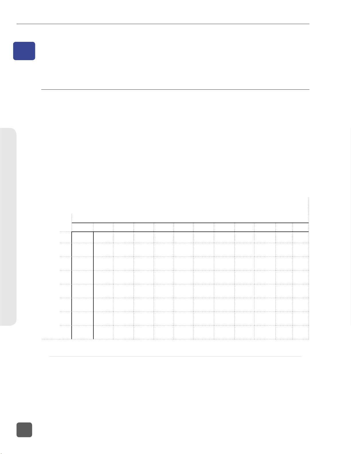
788T/788T-SSD User Guide and Technical Information
Routing and Mixing4
4
Routing and Mixing
Input to Track Routing
The 788T offers a great deal of routing fl exibility. Any input can be routed to any track. With this
powerful routing, iso tracks and sub-mixes can be recorded simultaneously.
Input to track routing is managed from any of four screens/controls:
• the Input Settings Window,
• the Setup Menu
• the Track Setup Window, or
• from an attached CL-8 (only tracks L, R, X1, and X2 can be routed from the CL-8).
• from an attached CL-9
• from the CL-WiFi application
Tracks are destinations for inputs, they can be routed to outputs and/or selected for recording. See
Track Arming. The following diagram displays the available input to track routing options, the check
marks and asterisks indicate factory default settings.
Tracks
1
2
3
4
5
Inputs
6
7
8
At Factory Default inputs are sent to Tracks L and R Post Fade and Tracks A -X2 Pre Fade.
L* R* A* B* C* D* E* F* G H X1 X2
* Track is Armed for Recording
34
Pre-Fade vs. Post Fade
Inputs can be assigned to tracks either pre- or post-fade. Pre-fade tracks are fed the respective input’s
audio signal immediately following the Trim level stage of the signal path. Fader adjustments have
no effect on pre-fade Tracks.
Post-fade tracks are fed the respective input’s audio signal immediately following the Fader level
stage of the signal path. Fader levels range is adjustable and is relative to the Trim level. Fader
adjustments do affect the audio signal sent to post-fade tracks. Pre- and post-fade assignments are
applied to all inputs routed to that track.
v. 3.02 Features and specifications are subject to change. Visit www.sounddevices.com for the latest documentation.
Page 43

788T/788T-SSD User Guide and Technical Information
Without a CL-2, CL-8, or CL-9 attached and with the front panel gain controls set to Trim Controls,
fader levels are fi xed at unity gain.
Routing Using the Input Settings Window
The Input to Track Routing in the Input Settings Window allows the user to quickly view and edit
the input-to-track routing for the selected input. The highlighted selections indicate the tracks that
the input is currently routed to. In order to record, tracks must be record enabled in the Track Setup
Menu.
To edit track assignments:
1. Enter the Input Se ings Window using the Input Selector Switch. The image below indicates
that Input 1 is currently assigned to Track L.
2. To make edits to the input to track assignments press the Play key.
3. Route or un-route the input to Track L and Track R by pressing the Rewind and Fast-Forward
keys respectively. Route or un-route the input to Tracks A-X2 using the Rotary Switch. Scroll
through the assignable tracks by turning the rotary switch. To route or un-route the input to
tracks, press in on the rotary switch.
4. Inputs can be sent to tracks pre or post fade. To toggle between the pre- and post-fade se ing,
press and hold the Rotary Switch. If the Track has a line above it is set as post-fade, if the
Track has a line below it is set as pre-fade. Pre- and post-fade assignments are applied to all
inputs routed to that track.
Routing and Mixing4
35
Page 44

788T/788T-SSD User Guide and Technical Information
5. The image below indicates that Input 1 is now routed to Track L post fade and
Track A pre fade. Once changes have been made, the se ings will be saved in the
INPUT : TRACK ROUTING Setup Menu option under the “Edited” routing selection.
6. To exit Input to Track Routing press the Play key.
Routing and Mixing4
7. The new track assignments will be visible from the Input Se ings Window.
Routing Using the Setup Menu
Press and hold STOP then press the INPUT key to bring up the following menu. This menu can also
be accessed via the Setup Menu option INPUT : TRACK ROUTING.
Continue to hold down the Stop key then press the INPUT key to cycle through the preset
input-to-track routing combinations. These presets are factory set and cannot be changed. The last
three preset selections are CU S TOM ROUTE options. Press the EDIT soft key to enter the custom rout-
ing menu. Custom routing allows any input to be assigned to any track. In the menu, highlighted
input and track combination are displayed in white text. The eight inputs are shown on the left; the
twelve tracks are shown on the right. Tracks can be assigned as pre or post fade, when the given
track is highlighted press the Play key to toggle between pre and post fade assignment.
36
v. 3.02 Features and specifications are subject to change. Visit www.sounddevices.com for the latest documentation.
Page 45

To assign custom input routings:
788T/788T-SSD User Guide and Technical Information
1. Press the
selet to move up
and down menu
2. Press the EDIT soft bu on ( ) and scroll to the appropriate input screen.
3. Using either the Rotary Switch or the up and down arrows, navigate to the desired input-to-
track combinations.
4. When a chosen pairing is highlighted, press either the ASSIGN soft key or the Rotary Switch
to assign the combination. Assigned tracks are noted on the screen by the addition of an arrow pointing to the record track.
5. Inputs can be assigned to tracks pre or post fade. Press the Play key to toggle between pre
and post fade routing per input. Pre- and post-fade assignments are applied to all inputs
routed to that track.
INPUT key until INPUT TRACK ROUT ING is displayed on the LCD display.
arrow indicates highlighted input is assigned
to highlighted track
select to exit menu
and apply selected
routing
select to remove
input assignment
highlighted selection indicates
if the input is sent pre or post
fade to the select track
6. Once a track is assigned, move to the next input-to-track combination desired.
7. To remove an input-to-track combination assignment, navigate to that combination and press
the UNASSIGN (LCD Backlight) soft key or the Rotary Switch.
8. Exit and complete the assignment by pressing the Check Mark (Tone) soft key.
The Input Routing menu will always exit to the main screen. Tracks must be armed in the Track Setup
Menu in order to record.
Routing Using The Track Setup Window
The Track Routing View within the Track Setup Window provides a useful global overview of all
input to track routing of the 788T. From this view, route any input to any track using the Rotary
Switch. Pre- or post-fade routing is applied as it is defi ned in the Input Settings Window or the Setup
Menu.
1. Enter the Track Setup Window by pressing the INPUT
key.
Routing and Mixing4
37
Page 46
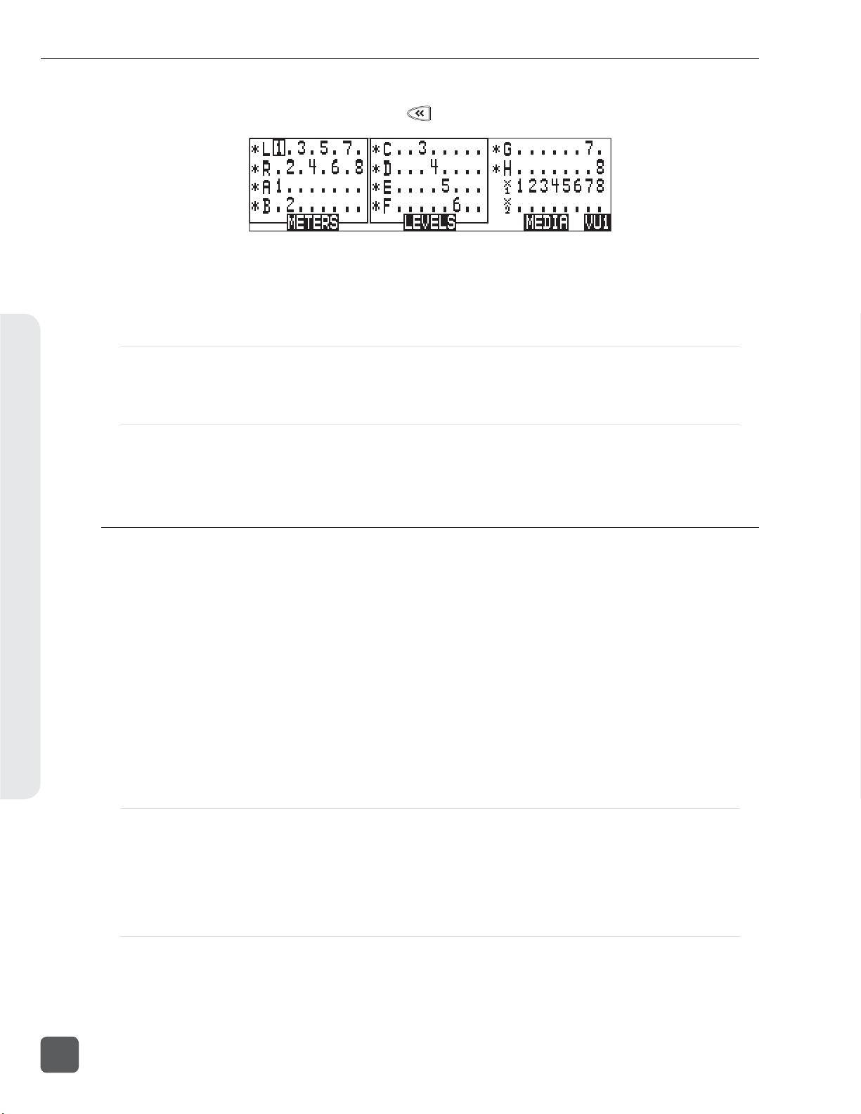
788T/788T-SSD User Guide and Technical Information
2. Press the soft ROUTING (REWIND) key to enter the Track Routing View.
3. Use the Rotary Switch to navigate through the Track Routings. If a number is displayed the
corresponding input is assigned to the given track.
4. Press in on the Rotary Switch to toggle the routing of an input to a track.
Routing Using the CL-8
From the CL-8 the user can quickly make input to track routing changes to the Left, Right, Aux 1,
and Aux 2 Tracks. See CL-8 Controller section for more details.
Routing Using the CL-9
From the CL-9 the user can quickly route any Input to any Track. See CL-9 Linear Fader Controller sec-
Routing and Mixing4
tion for more details.
Mix Assist™
Mix Assist™ is a powerful feature of the 788T which can automatically attenuate the level of any
microphone which is not active, reducing the background noise level in the mix. This function is
commonly referred to as “automix”. The 788T’s MixAssist™ feature automixes post-fade signals to
the L and R tracks. Pre-fade signals are not affected by Mix Assist.
Inputs that are automixed will be “open” (unattenuated) when a person talks into the input’s microphone and “closed” (attenuated) when the person stops talking. Microphone channels open within
1 mS to ensure that no syllables are lost, and then will gate off smoothly over 500mS. This gating
action is smooth and imperceptible when switching between microphones. Mix Assist will allow several microphones to be open simultaneously if there are several talkers - Mix Assist does not limit the
number of open microphones.
Mix Assist is more sophisticated than a simple gate, and uses four different principles to automix
input signals.
Noise Adaptive Threshold
An input with Mix Assist enabled will be smoothly attenuated by 20 dB when its microphone is below the adaptive threshold. The threshold is not a static level (as with the limiter or simple gate) but
a level which changes dynamically based on the average level of the input. This prevents common
background noise (fans, crowd murmur, etc) from causing the input to open, while allowing normal
sounds to open the mic.
38
Number of Open Microphone Attenuation
As the number of open inputs increases, the level of each input as it is routed to the track will decrease by 3 dB per doubling of open mics. This ensures that the overall level of the track is consistent
regardless of the amount of open inputs routed to it.
v. 3.02 Features and specifications are subject to change. Visit www.sounddevices.com for the latest documentation.
Page 47
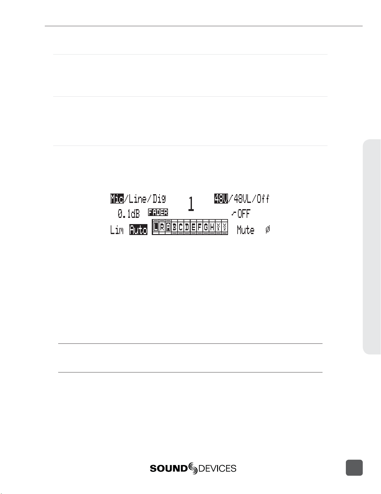
788T/788T-SSD User Guide and Technical Information
Last Mic Lock-On
When talking stops, the last input to be active will remain open. This maintains a consistent level of
natural sound and avoids a dramatic transition to silence on the track, even when no inputs are in
use.
One Mic Per Sound Source
Often a sound source (i.e. someone speaking) is captured by more than one microphone. Mix Assist actively compares signals from all inputs and when it senses the same audio on multiple inputs,
it will only open the input in which that specifi c program audio is loudest. Note that this does not
prevent another input from opening when unique program audio is sensed at that input.
Using Mix Assist
Mix Assist is enabled when the Setup Menu option MIXASS IST: MODE is set to
ON (LR TRACKS ONLY ) or ON (ALL TRACKS FOLLOW LR ). Each input to be automixed will then
have “AUTO” highlighted in the Input Settings window. Any input can then be switched to manual
operation, forcing that input to stay on regardless of level. Press the Rewind key in the Input Settings
Window to activate or deactivate Mix Assist for that input.
When ON (LR TRACKS ONLY ) is selected, Mix Assist attenuation is applied to the tracks L and R
only. This allows the user to simultaneously create both a mix-assisted mix on tracks L and R and a
manual mix on any other track set to post-fade. When ON (ALL TRACKS FOLLOW LR) is selected,
Mix Assist enabled inputs routed to post-fade tracks will be attenuated by Mix Assist.
The input activity LED ring will light bright green to indicate an automixed input that is currently
open. The input activity LED for closed inputs will be off. This input activity LED ring behavior
overrides the metering behavior of the input activity LED ring.
Inputs that are routed post-fader to track L or R and do not have automix activated will not be automixed but will still be analyzed by Mix Assist for the purposes of Last Mic Lock-On, One Mic Per
Sound Source, and Number of Open Mics Attenuation. The input activity LED ring for these inputs
will light dim green and show metering activity.
Mix Assist is a processor-intensive feature. Mix Assist is disabled when the sampling rate is above
48.048 kHz. Recording mono fi les is not recommended when using Mix Assist. Output Delay is not
recommended when using Mix Assist. When a CF card is in use, UDMA is recommended.
Routing and Mixing4
39
Page 48

788T/788T-SSD User Guide and Technical Information
Recording and Playback5
5
Recording and Playback
The 788T is a record-priority device. With very few exceptions (disk formatting, and fi le transfers),
pressing the REC key at any point during operation will initiate recording.
The largest, most easily accessed control on the 788T is its REC key. The 788T will immediately
enter Record mode when the REC key is pressed. If the storage media selected is not ready to begin
recording a new fi le, the REC key will fl ash red and the LCD will display REC ORD PE N DING until the
recording has begun.
When recording, the REC key, adjacent red LED, and the LCD backlight will all illuminate red to indicate that the unit is in record mode. The behavior of the LCD backlight can be adjusted with Setup
Menu option LCD: BACKLIGH T MODE.
Recording integrity is further enhanced through a process of periodic, automatic fi le directory and
header updates written to disk during recording. This ensures fi le integrity in the unlikely event of a
total loss of power.
If no tracks are armed to record, the 788T will not enter Record Mode. Make certain that at least one
record track is armed for recording.
While recording, the POWER, FAST FORWARD, REWIND, PLAY and TONE keys are disabled. See
Panel Lock to engage Panel Lock during recording. Stop recording by pressing and holding the STOP
key for at least 150 milliseconds.
items that affect recording are lined out in the menu list.
Although you can enter the Setup Menu during recording, menu
During recording, subsequent presses of the REC key can perform one of three Setup-Menu-selected
actions:
• no action,
• new cue - cue markers are set within the fi le being written,
• new fi le - a new fi le is started with each press of the REC key, the take counter increases by one.
Pre-Record Buffer
To prevent missing record cues or up-cutting takes, the 788T has a pre-record (or pre-roll) buffer.
When active, pre-record begins recording at a set number of seconds preceding the REC key being pressed. When recording higher sampling rates (48048 +) pre-roll is limited to fi ve seconds and
below.
Record buffering is disabled when the time code mode is set to Record Run. In External Time Code
Auto Record and External Time Code Continuous Auto Record modes, the Pre-Record Buffer is only
active from the time the 788T receives a valid time code signal. This allows the 788T to capture audio
before the set Time Code Hold Off value is reached. See Time Code Hold Off for additional information.
This prevents possible overlapping time code numbers between adjacent fi les.
Media Select
The 788T can record up to 12 tracks to all three available media (internal drive, CompactFlash, and
external hard drives) simultaneously at sampling rates of 48048 and below. Higher Sampling rates
are limited to eight tracks to two media only. When recording higher track counts and higher sam-
40
v. 3.02 Features and specifications are subject to change. Visit www.sounddevices.com for the latest documentation.
Page 49

788T/788T-SSD User Guide and Technical Information
pling rates, Sound Devices recommends using hard drives, solid state drives, and high speed UDMA
CompactFlash cards.
Media must be selected in the Setup Menu option REC : MED IA S ELEC T in order for material to be
written to it. Tracks can be individually routed to CompactFlash, Internal drive, and External media.
See Track-to-Media Routing.
Failure During Recording
In the event of a storage media failure, the specifi c error will be indicated on the LCD and warning
bells in the headphone monitor. Possible causes of media failure include, a hard drive in severe motion which results in recording errors, a CompactFlash card fi lling up while recording, or an external
DVD-RAM that can’t keep up with the chosen data rate, track count, or fi le type. If more than one
drive is selected for recording, the remaining drives will continue recording without failure. If a media continues to be displayed as slow after the warning prompt has been cleared, press the Stop key
to clear the Slow status.
Record Timer
The 788T is equipped with a record start and stop timer. This allows a user to record a take
at a specifi c time from an unattended recorder. Set the start time in the Setup Menu option REC : TIMER START then set the record stop time in the Setup Menu option REC: TIMER STOP.
The 788T will boot up and start recording when the timer start time elapses.
Track Arming
The 788T only records tracks that are armed. Armed tracks are tracks that are both record enabled
and have active inputs routed to them. Track Enabling is controlled in the Track Setup Menu. To enable a track for recording perform the following steps.
1. Enter the Track Setup Menu by pressing the INPUT key.
2. Navigate through the Tracks using the Rotary Switch. The Track with the box around it is the
selected track. This is Track L in the above image.
3. A solid * (asterisks) in front of a given track indicates that the track is armed. Flashing * (as-
terisks) indicate that the track is enabled for recording but an active input is not routed to it,
and the track will not be recorded. Enable/Disable select tracks by pressing in on the Rotary
Switch. The above image indicates that Tracks L, R, A, B, C, D, E, F, G, and H are enabled for
recording. Tracks X1 and X2 may have inputs routed to them, but are not enabled and will
not be recorded.
4. Exit the Track Setup Menu by pressing the INPUT key.
Recording and Playback5
When recording higher track counts or higher sampling rates, Sound Devices recommends using solid
state drives, hard drives, and high speed UDMA CompactFlash cards.
41
Page 50

788T/788T-SSD User Guide and Technical Information
Track Enabling Using the CL-9
From the CL-9 the user can quickly enable any Track for recording. See CL-9 Linear Fader Controller
section for more details.
Track Status Indication
Track status is indicated by the blue Track LEDs located on the 788T front panel and by the asterisks
in the Track Setup Window. The LED and asterisks are solid when a track is ready to record (Armed).
The LED and asterisks fl ash to indicate that the track is record enabled but no active input is routed
to it and therefore will not record. The Track LED remains off and the asterisks disappears when the
Track is disabled.
The fl ashing behavior of the Track LED’s can be disabled by setting the menu option
METER : TRACK ARM LEDS to Show Arm Status Only.
Recording and Playback5
Track LED/
Track Status Description
Asterisk
Status
Off
Flashing
Solid
Track is disabled and will not be recorded. Track has been disabled in the Track Setup Window or by
Track is enabled but will not be recorded. Track has been enabled in the Track Setup Window or by
Track is Armed, enabled and will be
recorded.
pressing the CL-9 Track Button. This is useful when using a
track as an output or monitoring bus.
pressing the CL-9 Track Button but the track is not armed for
any one of the following reasons:
• No inputs are routed to the track
• Inputs routed to the track are not turned on
• Track is not routed to a media in the Track-to-Media menu.
Track has been enabled in the Track Setup Window or by
pressing the CL-9 Track Button and there is one or more active inputs routed to it.
Track-to-Media Routing
From the Track-to-Media View, tracks are individually assigned to CompactFlash, Internal Drive, or
External media. This is extremely useful for those recording to a deliverable media, but only select
tracks need to be delivered. For Example, the specifi c application may require ten-track recordings,
two-track stereo mix and eight isolated tracks. Instead of recording ten tracks to all three media, the
user can select which tracks are written to each media. The user may opt to record all ten tracks to
internal drive, eight isolated tracks to CompactFlash, and the two-track stereo mix to DVD-RAM.
The media status on the Main Display toggles between Remaining Time and Track Count when the
given media is set to receive less than the full amount of armed tracks.
42
By default, all tracks are assigned to all available media. Tracks will only be written to a given media
if the media is selected in the Setup Menu option REC : MED IA S ELEC T, regardless of it’s Track-to-
Media routing status. See Media Select.
v. 3.02 Features and specifications are subject to change. Visit www.sounddevices.com for the latest documentation.
Page 51

788T/788T-SSD User Guide and Technical Information
To assign tracks-to-media perform the following steps.
1. Enter the Track Setup Window by pressing the INPUT key.
2. Press the soft MEDIA (Fast Forward) key to enter the Track-to-Media View.
3. Use the Rotary Switch to navigate through the track-to-media routing. If media is displayed
the corresponding track will be wri en to that media, that is, if the media has been selected in
the Setup Menu and the track is armed. In the illustration above, the external hard drive will
only write Tracks L and R.
4. Press in on the Rotary Switch to toggle the routing status of a media.
Master Gain Levels
The master gain levels are controlled independently for the Left, Right, X1, and X2 Tracks. The Left
and Right tracks and the X1 and X2 Aux Tracks can be linked, allowing one level control for both
tracks of the pair. Levels are adjustable from -60 to +15 dB in .1 dB increments. The master gain level
is applied to the Tracks prior to recording. This allows the Sound Mixer to adjust the overall mixed
signal of all summed inputs routed to these tracks. Follow these steps to adjust the master gain level.
1. Press the INPUT
2. Press the soft Levels (Play) key to access the Master Gain Levels View.
key to access the Track Setup Window.
Recording and Playback5
43
Page 52

788T/788T-SSD User Guide and Technical Information
3. Press the soft L/R (Rewind) or the soft AUX (Fast Forward) key to select the pair of tracks to
be adjusted. This is indicated by the box around the Left and Right Track Meters as shown
in the above image. Tracks are adjusted independently or as a linked stereo pair. To adjust
the gain of each track independently, press the Rewind or Fast Forward key respectively to
highlight the Track to be adjusted. To link the tracks as a stereo pair, press the Rewind or Fast
Forward key respectively to highlight both the L, R or the X1, X2 tracks.
4. Turn the Rotary Switch to a enuate the master gain level in .1 dB increments. Press in on the
Rotary Switch to immediately return to unity gain (0 dB).
5. Press the soft Tracks (Play) key to return to the Track Setup Window.
Track Limiters
Track Limiters prevent multiple summed inputs from overloading the track prior to being recorded.
The Left, Right, X1, and X2 tracks are all equipped with their own track limiter. Track Limiter and the
Input Limiters share the same characteristics as defi ned in the Setup Menu.
Track Limiters are turned on by pressing the soft LIM (LCD Backlight) key in the Master Gain Levels
View. Limiters settings are applied to both tracks in the pair. Tracks are paired as Left, Right and X1,
X2.
Recording and Playback5
The Track Limiters can either be linked as a stereo pair (LINKED) or can work as two independent
limiters (ON). When linked, the limiters will apply the same gain reduction equally to both tracks of
the pair. LINKED is recommended when recording stereo program, so that level changes are identical on both tracks. ON is recommended when using the tracks of the pair as two separate buses.
Track Limiter activity is displayed in the Master Gain Levels Window. Track Limiter Indicators will
appear when the Track Limiters are engaged. When Limiters are LINKED the indicators will be connected with a line. The Indicators are solid when the limiter is active. In the image below, the Left
and Right Track Limiters are LINKED and actively limiting. The Aux Track Limiters are ON and
only the X1 Track Limiter is actively limiting.
Master Gain Levels Using the CL-9
The CL-9 has dedicated physical master gain controls for the Left, Right, Aux 1, and Aux 2 Tracks.
When the CL-9 is attached the Master Level Gains can only be adjusted using these level controls.
Master Track Linking is still performed on the 788T in the Master Gain Levels Window. See CL-9
Linear Fader Controller section for more details.
Sampling Rate and Bit Depth
The 788T generates uncompressed PCM audio WAV fi les in the Broadcast Wave File format at the
user-selected sampling rate and bit depth. The 788T LCD displays the remaining available recording time based on the sampling rate, bit depth, number of assigned tracks, and the selected storage
media’s available capacity. See Apendix A - Record Time Calculation.
44
v. 3.02 Features and specifications are subject to change. Visit www.sounddevices.com for the latest documentation.
Page 53

788T/788T-SSD User Guide and Technical Information
Sampling Rate
When a sampling rate is selected for recording, all tracks are recorded at the selected sampling
rate. Sampling rates are selected among common rates from 32 kHz to 192 kHz. Additionally, nonstandard sampling rates can be applied when the 788T is word clocked from an external source
(clock sources between 32 kHz and 192 kHz). When recording off-speed sampling rates, fi les will be
stamped with the rate closest to the internally generated frequency.
Sampling Frequency and Audio Bandwidth
The sampling frequency is expressed in samples per second (hertz) and defi nes the number of times
in a second that the analog audio signal has been measured. Sampling frequency determines the
audio bandwidth, or frequency response, that can be represented by the digital signal. A quick estimate of the maximum bandwidth capable of being represented at a given sampling rate is maximum
analog frequency = sampling frequency/2. Higher sampling frequencies allow for wider audio
bandwidth.
The 788T generates the following sampling rates:
• 32 kHz
• 44.1 kHz
• 47.952 kHz
• 47.952 kHz “F Mode”
• 48 kHz
See Time Code for more information about F Mode sample rates.
• 48.048 kHz
• 48.048 kHz “F Mode”
• 88.2 kHz
• 96 kHz
• 96.096 kHz
• 96.096 kHz “F Mode”
• 176.4 kHz
• 192 kHz
Considerations When Recording With High Sample Rates
Increasing the sample rate above 48.048 kHz requires certain settings to be adjusted and imposes
certain limits to some features. Increasing the sample rate above 96.096 kHz furthers these requirements. It is recommended to save settings for work fl ows with a high sample rate, so they can be
easily recalled.
Feature > 48.048 kHz > 96.096 kHz
Tracks * 8 tracks total (any) * Up to 4 tracks (Tracks C-X2 disabled) *
Input Limiters Disabled
Recording to DVD-RAM Not supported
High speed (UDMA) CF Advised Required
Storage media 2 max 1 max
Input delay 15 ms max 7.5 ms max
EQ (CL-9) Disabled
MixAssist Disabled
High Pass filters Available Disabled
Pre-roll 5 sec. max 2 sec. max
Recording and Playback5
45
Page 54

788T/788T-SSD User Guide and Technical Information
Feature > 48.048 kHz > 96.096 kHz
Timecode Hold-off 4 sec. max 2 sec. max
Wave Agent Control Available Disabled
* Track counts here refer to the number of enabled Tracks. Unused Tracks must be disabled by pushing
the Input key and using the Rotary Encoder to remove the asterisk from them.
Steps to Prepare for Recording at 88.2 kHz - 96.096 kHz Sample Rate
1. Access Setup Menu option REC : MED IA S ELE CT and choose any option of 2 media or less.
Recording and Playback5
2. Pres the Input
3. Using the Rotary Switch, navigate the Tracks and disable Tracks so that 8 or less Tracks are
enabled. Enabled Tracks are indicated by an asterisk and disabled Tracks have no asterisk.
4. Press the Stop key to return to the Main Screen.
5. Access the Setup Menu option REC: SAMPLE RA TE and choose the desired sampling rate.
key to access the Track Setup Window.
Steps to Prepare for Recording at 176.4 kHz -192 kHz Sample Rate
1. Access Setup Menu option REC : MED IA S ELE CT and choose any option of 1 media.
2. Pres the Input
3. Using the Rotary Switch, navigate the Tracks and disable all Tracks from C to X2 (All but L,
R, A, and B). Enabled Tracks are indicated by an asterisk and disabled Tracks have no asterisk.
4. Press the ROUTING (Rewind)
5. Using the Rotary Switch, navigate the track routings, removing all routing on Tracks C
through X2. Tracks C, D, E, F, G, H, X1, and X2 must have no inputs routed to them.
6. Press the Stop key to return to the Main Screen.
7. Access the Setup Menu option REC: SAMPLE RA TE and choose the desired sampling rate.
key to access the Track Setup Window.
key to access the Track Routing View.
Bit Depth
46
The 788T records at bit depths of either 16 or 24 bits. 24-bit recording provides greater dynamic
range and addition headroom for signal peaks relative to 16-bit recordings. 24-bit recording (versus
16-bit) is a signifi cant benefi t for fi eld production audio tracks.
Bit Depth and Dynamic Range
Bit depth defi nes the digital “word length” used to represent a given sample. Bit depth correlates to
the maximum dynamic range that can be represented by the digital signal. Larger bit depths accommodate more dynamic range. A quick estimate of the maximum dynamic range capable of being
represented by a given word length is dynamic range ~= no. of bits x 6 dB. Bit depth is an exponen-
v. 3.02 Features and specifications are subject to change. Visit www.sounddevices.com for the latest documentation.
Page 55

788T/788T-SSD User Guide and Technical Information
tial measure (exponent of 2), so as bit depth increases, the amount of data it represents increases
exponentially. The majority of fi eld recording is done with 16-bit audio, therefore, each sample is represented by a digital word of 2^16 (65,536) possible values. 24-bit audio has a word length of 2^24
(16.7 million) possible values per sample.
The 788T has 24-bit analog-to-digital converters. To obtain 16-bit recording the 788T can be set to
dither 24-bit digital signals to 16-bit. The 788T uses a proprietary pseudo-random dither routine
for accurate bit rate reduction. Dither can be defeated in the Bit Depth Setup Menu option. Without
dither, 24-bit audio is truncated to 16-bit, meaning the least signifi cant 8 bits are discarded.
Once a fi le is recorded its sampling rate and bit depth can not be changed in the recorder. File conversion
must be done in another environment, such as an audio workstation.
Audio File Formats
The 788T records audio to the industry-standard Broadcast Wave fi le format, either monophonic or
polyphonic. Additionally, the 788T will also playback fi les in the WAV, MP2, or MP3 formats. The
788T will also read fi les with the .BWF extension.
.WAV
The 788T writes AES-31 Broadcast Wave formatted fi les. The audio fi les created by the 788T include
additional information (Metadata) in the fi le’s header, BEXT (Broadcast Audio Extension) and iXML
data chunks. See Appendix 2 – Metadata Implementation. Software that does not recognize these additional broadcast wave data chunks will simply ignore them.
File Type
The 788T has two fi le type options for recording, WAV mono and WAV poly. Select the fi le type in
the Setup Menu option REC: F ILE T YPE.
Monophonic
When WAV Mono is selected, the 788T will generate a separate audio fi le for each recorded track.
The mono fi les generated by the 788T have fi le names similar to T01_1.WAV and T01_2.WAV. The fi le
name suffi xes, _1 and _2, identify the track number of the fi le. If a take contains 10+ mono tracks the
tracks will be suffi xed with _A (10), _B (11), _C (12).
Polyphonic
When WAV Poly is selected, the 788T will generate one audio fi le for each take. All recorded tracks
are interleaved into this single fi le.
Wave Agent Beta allows for the splitting (de-interleaving) of polyphonic fi les and combining (merging or
interleaving) of monophonic sibling fi les into a single polyphonic fi le. See Wave Agent Beta.
Recording and Playback5
Take Management
A Take is a single recording which is composed of one or more audio fi les.
47
Page 56

788T/788T-SSD User Guide and Technical Information
For polyphonic wav fi le recordings, a take is represented by a single polyphonic fi le generated at the
time of recording. The single polyphonic fi le contains all the tracks of the take. In this case, since the
take is represented by this one fi le, its name is the same as the fi le’s name.
In the 788T, a polyphonic take/fi le name consists of a scene name, take number, and a fi le extension.
For example, for scene S01, take T01, the polyphonic fi le name and take name are both S01T01.wav.
For monophonic wav fi le recording, a take is represented by a group of monophonic fi les generated
at the time of recording. Each monophonic fi le represents an individual track of the take. In this case,
since the take is represented by several fi les, its take name is the same as any of the constituent fi les’
names except with the track number suffi x is replaced by ‘_X’.
In the 788T, a monophonic fi le name consists of a scene name, take number, track number suffi x and
a fi le extension. See Appendix 3 – File Naming. For example, for scene S01, take T01, comprising of 4
tracks, the monophonic fi le names are S01T01_1.wav, S01T01_2.wav, S01T01_3.wav, S01T01_4.wav,
and the take name is S01T01_X.wav.
S01T01_1.WAV
Recording and Playback5
scene
number
take
number
mono
file
designator
extension
Scene Name/Numbering
Scene names are selected for use from a scene name list. This list is managed in the Setup Menu option REC : S CENE NAME/NUMBER. Any number of scene name lists can be generated and these can be
made up of any number of scene names. The advantage of scene name lists is that frequently used
scene names can be compiled before production starts.
Scene names are made with alphanumeric characters, including “_ ” and “-” and can be any length
between zero (0) and nine (9) characters. Scene numbers help to match audio with the corresponding
scene in a production. Scene names can also be used to identify other items, including roll number,
recording date, artist name or any other descriptor as required.
Scene names are user-selected in the Setup Menu and do not change until changed by the user.
48
To change scene numbers:
1. Enter the user menu and navigate to the Scene Name/Number option.
v. 3.02 Features and specifications are subject to change. Visit www.sounddevices.com for the latest documentation.
Page 57

788T/788T-SSD User Guide and Technical Information
2. Use the REWIND (<<) and FAST FORWARD (>>) soft keys to move among characters. Use
the PLAY key to delete characters. Characters are entered from left to right and deleted from
right to left.
3. Use the Rotary Switch or the Up and Down Arrow soft keys to choose characters. Press the
Rotary Switch or press the FAST FORWARD key to save the character and move to the next
position.
4. To save the scene name, press the soft Check Mark (TONE) key or press in on the Rotary
Switch without selecting a character. After the ninth character is entered, the scene name is
automatically saved.
If all characters are removed, no scene name will be written to fi les.
Scene Name Incrementing/Decrementing
Scene Names can be quickly incremented from the main screen by pressing and holding the Stop
key and then the Fast Forward key. See Front Panel Button Shortcuts. Scenes will be incremented by
either alpha characters (A,B,C...) or numeric digits (1,2,3...). This is selectable by the user in the Setup
Menu option REC : S CENE INCREMENT MODE.
To increment the Scene Name/Number from the Take List.
1. Press the HDD key to access the Take List.
Recording and Playback5
49
Page 58

788T/788T-SSD User Guide and Technical Information
2. Scroll to the top of the Take List and highlight the next take, which is indicated by the le er n.
3. Press the soft Scene +/- (Fast Forward) key to enter the Scene increment/decrement screen.
Recording and Playback5
4. Press the soft Scene + (Fast Forward) key to increment the scene name from WILDCAT1T02.
WAV to WILDCAT2T01.WAV.
5. Press the soft Done (Play) key.
6. The name of the next take will be displayed on the top line indicated by the n.
50
v. 3.02 Features and specifications are subject to change. Visit www.sounddevices.com for the latest documentation.
Page 59

788T/788T-SSD User Guide and Technical Information
Take Numbers
Take numbers are integers between 01 and 99, 999, with or without preceding zeros, which increase by one each time a new fi le is recorded. Take numbers can be set with or without a take
separator, such as the character “-” or “T”. The take separator can be used to clearly identify
the take number within the fi le name. Take numbers are managed in the Setup Menu option
REC: T AKE N AME/NUMBE R. Take numbers can be incremented and decremented in the Take List.
If the 788T detects a take/fi le with the same name in the destination folder, a letter suffi x, starting
with “A” is added to the take/fi le name, before the extension.
To change take numbers:
1. Enter the Setup Menu and navigate to the Take Name/Number option.
2. Use the REWIND (<<) and FAST FORWARD (>>) soft keys to move among decimal places
and to jump to the single alphanumeric take spacer character. Use the PLAY key to reset the
take number to 1. Characters are entered from left to right and deleted from right to left.
Do not use the underscore (“_”) character as a take spacer. Since this character is used to designate mono
tracks when recording mono WAV fi les can cause confusion.
3. The Rotary Switch or the soft keys are used to choose characters/numbers. Press the soft
Check Mark (TONE) key or press in on the Rotary Switch to save the character and move to
the next position.
From the Setup Menu the action for take resetting is controlled by the following options:
• Never – take numbers do not reset
• When scene is changed – take resets when scene name is changed
• When daily folder is changed – takes reset on new day
• Either scene or daily– takes reset on either change
Take Number Incrementing/Decrementing
Take increments and decrements can be made in the Take List. To increment and decrement takes.
1. Press the HDD key to access the Take List.
2. Scroll to the top of the Take List and highlight the next take, which is indicated by the le er n.
Recording and Playback5
3. Press the soft Take +/- (Fast Forward) key to enter the Take Increment/Decrement screen.
4. Press the soft Take + (Fast Forward) key to increment or the Take - (Rewind) key to decrement
the take.
5. Press the soft Done (Play) key.
6. The name of the next take will be displayed on the top line indicated by the le er n.
51
Page 60
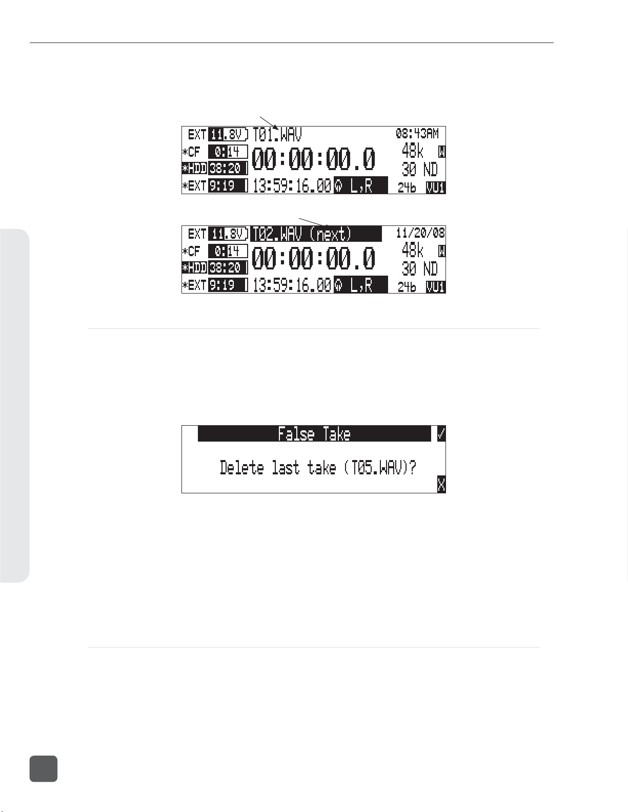
788T/788T-SSD User Guide and Technical Information
7. Exit the Take List by pressing X.
8. Press and hold the STOP key to display the next incremented take’s fi le name.
Indicates active take
Indicates next upcoming take
Recording and Playback5
False Take Control
To identify a take as a False Take, perform the following:
1. Press the STOP key to end the recording.
2. Wait for the fi le to fi nish writing, the activity LED will turn from orange to green.
3. Simultaneously press the STOP and REWIND keys to be prompted to delete the most recent
take.
4. Press the soft Check Mark (TONE) key to delete the take.
Alternatively, the last take can be identifi ed as a False Take from within the Take List. This can be
done by decrementing the take number to match the most recent recorded take’s fi lename.
Files that have been confi rmed as false takes are moved to the FALSETAKES folder. When recording to internal drive, CompactFlash, and external FireWire storage devices, fi les determined as False
Takes will be moved to the FALSETAKES folder on each storage media that the fi le has been written to. This folder sits in the drive root. False Takes will remain on the drive until the FALSETAKES
folder is emptied.
52
Emptying the False Take Folders
Files that have been moved to the False Take folders can be permanently deleted from each media
in the Drive Options Menu by selecting EMPTY T RAS H. Each drive has its own False Take folder and
they are permanently deleted independently. Once the False Take folder has been emptied, any fi les
it contains are permanently deleted and cannot be recovered. See Emptying the Trash for more details.
v. 3.02 Features and specifications are subject to change. Visit www.sounddevices.com for the latest documentation.
Page 61
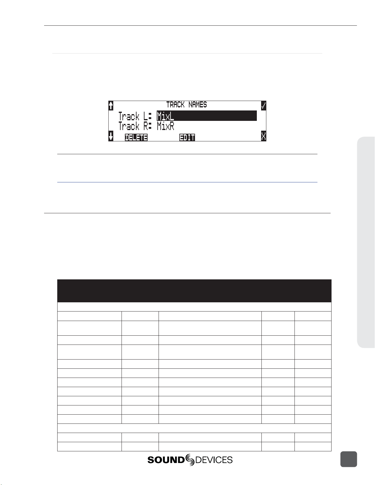
788T/788T-SSD User Guide and Technical Information
Track Naming
Each track in a fi le, whether monophonic or polyphonic, can be named with a unique, descriptive
track name. Descriptive track names such as ‘radio mic 1’, ‘boom 2’ or ‘John Smith’ are more helpful
to editors than track numbers. Track names with up to 26 characters are managed in the Setup Menu
option REC : TRACK NAMES. The track names selected prior to recording are stored in the Broadcast
Wave Extension (BEXT) data as well as in the iXML data.
When Setup Menu option CONNECTION MODE is set to C-LINK METADATA SHARING, editing the
track name on the C.Link master unit will also change the respective track name on the C.Link slave unit.
see C.Link Metadata Sharing
Metadata Implementation
788T Broadcast wave fi les include iXML (revision 1.5) data and bEXT chunk data. For bEXT and
iXML-aware software applications this data is available. For applications that don’t recognize bEXT
or iXML, this information is ignored. The chart below details the supported metadata parameters.
• iXML: Metadata stored in the Broadcast Wave iXML chunk
• bEXT: Metadata stored in the Broadcast Wave bEXT chunk
• FMT: Metadata stored in the Broadcast Wave Format chunk
= supported; blank = not supported
Metadata Type Notes
M = Automatically Entered by the Machine
General Information
Project
Roll (Tape)
Scene
Take
Notes
Circle Take
File UID
File Sample Rate
Digitizer Sample Rate
Bit Depth
Channels
Time Code Information
Frame Rate
TC Flag (ND or NDF)
iXML U; via Folder Options menu Top-Level
iXML, bEXT M; uses creation date or is overridden by User
U; via Folder Options menu Mid-Level
iXML, bEXT U; via Scene Name menu
iXML, bEXT M or
U; via Take Name menu
iXML, bEXT U; via HDD menu
iXML U; via Take List menu
iXML M; Unique File Identifier
iXML, FMT U; via the Sample Rate menu
iXML U; Actual sample rate of AD converter
iXML, FMT U; via Bit Depth menu
iXML, FMT U; Number of channels (tracks) in the file
iXML, bEXT U; via Frame Rate menu
iXML, bEXT U; via Frame Rate menu
U = Entered by User
Read Write
Recording and Playback5
53
Page 62

788T/788T-SSD User Guide and Technical Information
Recording and Playback5
Start Time Code
Duration
U-Bits
Time Code Sample Rate
Track Information
Channel Index
Interleave Index
Track Name
Speed Information
Master Speed
Current Speed
Speed Note
Originator Information
Originator
Creation Date
Creation Time
Originator Reference
Software Version
File Set Information
Family UID
Total Files
File Set Index
File History
Original File Name
iXML, bEXT M; Stored as a sample count since midnight
M
iXML, bEXT U
iXML M
iXML M; Track Number
iXML M
iXML, bEXT U; via Track Names menu or HDD menu
iXML M
iXML M
iXML M
bEXT M
bEXT M
bEXT M
bEXT M
bEXT M
iXML M; shared by files belonging to the same take
iXML M; number of files representing a take
iXML M
iXML M
Take List
The Take List contains a list of every Polyphonic or Monophonic take that has been recorded on the
788T. The name of the take is displayed on the left side of the Take List. The right side of the Take
List displays additional fi le information. Press the Rotary Switch to toggle the type of information
displayed. Each press will toggle between the following information.
• Beginning time code stamp
• Time of fi le creation
• Date of fi le creation
The Take List is accessed via the Setup Menu option FILE: VIEW TAKE LIST or by pressing the
HDD key.
The following functions are performed within the Take List.
• Increment/Decrement Scene and Takes
• Edit metadata and rename fi les
• Scene name
• Drives that contain the fi le
• Folder that contains the fi le
54
v. 3.02 Features and specifications are subject to change. Visit www.sounddevices.com for the latest documentation.
Page 63

788T/788T-SSD User Guide and Technical Information
Metadata edits performed in the Take List are applied across all connected media on which the take
resides.
The File Viewer (Drive Directory) is accessed by pressing the soft DRV (HDD) key from within the Take
List or via the Setup Menu option FILE: VIEW FILES.
Refresh Take Metadata
During power up, the 788T automatically loads the metadata for the last 100 fi les (mono and poly)
recorded. “Building List” will be displayed if the Take List is entered while the fi rst 100 fi les are
loading. Takes containing fi les beyond the most recent 100 fi les will need to be loaded manually by
pressing the soft REFRESH (Play) key.
Take Edit Menu
From this menu, the user can perform the following edit operations while the recorder is in Standby
or Record modes:
• Notes *
• Rename
• Circle *
• Project
• Scene *
• Take *
• Tape (Roll)
* When Notes, Circle, Scene, or Take are edited on a C.Link master unit with Setup Menu option
CONNECT I ON MODE set to C- LINK METADATA SHARING, this metadata will also be changed for the
corresponding take on the C.Link slave unit. see C.Link Metadata Sharing
Follow these steps to access the Take Edit Menu.
1. Enter the Take List by pressing the HDD key.
2. Choose any Take from the Take List.
3. Press the soft Edit (PLAY) key to enter the Take Edit Menu.
• Set Copy Flag
• Clr Copy Flag
• Delete (sends fi le to the Trash /Postrecord only)
• Load Settings
• Rename Tracks
Recording and Playback5
55
Page 64

788T/788T-SSD User Guide and Technical Information
Post-record metadata editing can also be performed with Sound Devices Wave Agent Beta. See Wave
Agent Beta for more details.
Notes
Notes can be added to a Take to describe its contents. BEXT and iXML support notes fi elds. To add
notes to a Take:
Recording and Playback5
1. Enter the Take List by pressing the
2. Highlight the desired fi le.
3. Press the soft EDIT (Play) key to access the Take Edit Menu.
4. Select Notes
5. Enter text in the Notes fi eld using the Rotary Switch or a USB Keyboard.
6. Press the soft Check Mark (TONE) key or simultaneously press the CTRL and Enter keys
from a USB Keyboard to save Notes. Pressing the soft X (LCD BACKLIGHT) key or Esc on a
USB Keyboard will cancel the Notes entry.
HDD key.
Renaming Takes
Takes can be renamed in the Take Edit Menu during and after recording. Renaming a take renames
its associated fi les and updates their embedded metadata. Edits made to the Take name are applied
across all media and associated mono fi les. The new name can be up to 26 characters in length including the .WAV extension.
56
Duplicate Takes
In the event of a duplicate take name, the 788T will detect that a fi le with the same name already
exists and will ask if a duplicate fi le should be created. If the user selects to do so, the resulting fi le
name will be pre-fi xed with a +. If this occurs for more than two fi les, an additional + will be added
respectively for every fi le altered.
v. 3.02 Features and specifications are subject to change. Visit www.sounddevices.com for the latest documentation.
Page 65

788T/788T-SSD User Guide and Technical Information
Circle Take
Take names can be altered to include the “@” symbol preceding the fi le name. This can be used to
highlight a take as a “Circled Take”. Circled Takes are often used to identify good takes for transferring. Circle Take information is also embedded within the BEXT and IXML data chunks.
To Circle or uncircle a take, perform the following steps:
1. Press the STOP key to end the recording.
2. Press the HDD key to enter the Take List.
3. Scroll among fi les to highlight the fi le as a Circled Take.
4. Press the soft EDIT (PLAY) key to enter the Take Edit Menu.
5. Highlight and select the Circle option from the list. This will toggle the Circle indication on
and off .
Project
Edits can be made to the Project fi eld during and after recording. The Project fi eld by default is the
name of the Top-Level folder defi ned in the Setup Menu option FILE: FOLDER OPTIONS. Project
metadata is embedded within the BEXT and IXML data chunks.
Scene
Scene name edits can be made during and after recording. Any changes to the Scene name are applied to both the fi le name and the Scene tag in the iXML and bEXT chuncks.
Take
Take number edits can be made during and after recording. Any changes to the Take are applied to
both the fi le name and the Take tag in the iXML and bEXT chunks.
Tape (Roll)
Recording and Playback5
Edits can be made to the Tape (Roll) iXML tag during and after recording. The Tape (Roll)
fi eld by default is the name of the Mid-Level folder defi ned in the Setup Menu option
FILE: FOLDER O PTION S . Tape (Roll) metadata is embedded within the BEXT and IXML data
chunks.
Set and Clear Copy Flags
Copy Flags are useful for selecting various takes to be copied from one media to another. By
default, Takes recorded by the 788T have their Copy Flag set to On. If the Setup Menu option
FILE: COPY FLAG RESET is enabled the Copy Flags will automatically clear after the fi le has been
copied from one media to another. See File Copying Among Available Media.
57
Page 66

788T/788T-SSD User Guide and Technical Information
Deleting Takes
Takes and their associated fi les are now deleted from the Take List Edit Menu. Deleted fi les are sent
to the respective media’s Trash Folder. The Trash Folder is emptied via the Drive Directory Options
Menu.
To send a Take to the Trash Folder.
1. Enter the Take List by pressing the HDD key.
2. Highlight the fi le that you wish to delete.
3. Press the soft Edit (Play) key to access the Edit Menu.
Recording and Playback5
4. Highlight and select the Delete option.
5. The Confi rm Take Delete window appears. Select which drives the fi le should be deleted
from using the soft CF, HDD, and EXT (Rewind, Play, and Fast Forward) keys. The take will
be deleted from any drive that is highlighted.
6. For example, if the fi le WILDCAT2T01.WAV is to only be sent to the EXT drive Trash Folder,
press the soft CF and HDD (Rewind and Play) keys to deselect the drives.
58
v. 3.02 Features and specifications are subject to change. Visit www.sounddevices.com for the latest documentation.
Page 67
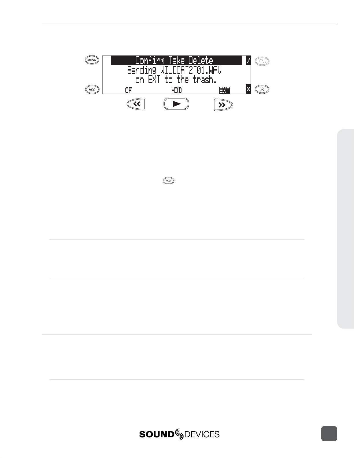
788T/788T-SSD User Guide and Technical Information
7. Press the soft Check Mark (Tone) key to send the take to the Trash Folder.
Load Settings
User Settings can be recalled from any take recorded by the 788T post fi rmware revision post 2.18.
See Saving and Recalling User Settings
Renaming Tracks
Track names can be renamed during and after recording via the Take List. To rename a track:
1. Enter the Take List by pressing the
2. Highlight the desired take to be edited.
3. Press the soft EDIT (PLAY) key to access the Take Edit Menu.
4. Highlight and select the track that is to be renamed.
5. Rename the track and press the soft Check Mark (TONE) key to save the new track name.
HDD key.
Wave Agent Metadata Entry and Editing
Sound Devices Wave Agent Control Mode allows a Sound Devices 788T or 788T-SSD to be connected
to Wave Agent over USB. When connected, Wave Agent can be used to enter or edit various metadata fi elds for the previous, current, and upcoming takes. See Wave Agent Control for details.
CL-WiFi Metering and Display
With a CL-WIFI accessory connected to the C. Link in jack, an ad-hoc wireless connection can be established between the 788T and any Apple iOS device. The CL-WiFi application running on the iOS
devices can be used to enter or edit various metadata fi elds for the previous, current, and upcoming
takes. See CL-WIFI for details.
CSV Sound Reports
The 788T can generate sound reports as a comma separated values (CSV) fi le. CSV fi les can be
opened and edited by common text editors and spreadsheet applications such as Microsoft Excel,
OpenOffi ce Calc, Apple Numbers, Google Docs.
Recording and Playback5
Sound Report Setup
A sound report consists of two sections: A Take List section which provides information for each
take in the folder the sound report was generated in, and an Overview section that contains ancillary
information to the Take List section. The Overview section is fi rst, followed by the Take List section.
59
Page 68

788T/788T-SSD User Guide and Technical Information
Overview Section
The table below lists the rows that make up the Overview section.
Row Description Default
Project: The name of the project.
Producer: The name of the producer.
Director: The name of the director.
Job: The title of the job.
The date. The <System Date> option will insert the current system
date (In MM/DD/YY format) at the time the report is generated.
Production company telephone number. Limited to numbers and
symbols.
File type. Options are <Current Selection> (WAV Poly or WAV Mono)
or <None>
Sample rate of recorded audio. Options are <Current Selection> (At
time of report generation) or <None>
Timecode frame rate. Options are <Current Selection> (At time of
report generation) or <None>
Bit depth of recorded audio. Options are <Current Selection> (At time
of report generation) or <None>
The amplitude of the 788T’s tone generator. Options are <Current
Selection> (At time of report generation) or <None>
Recording and Playback5
Date:
Location: The location.
Sound Mixer: Your name.
Phone: Your phone number. Limited to numbers and symbols.
Email: Your email address.
Client: Client’s name.
Boom Op: Boom operator’s name.
Prod.Co: The name of the production company.
Prod.Co. Tel:
Mics: Notes about mics used.
Comments: Miscellaneous comments.
Roll: The roll / daily identifier.
Media: Media type
File Type:
Sample Rate:
Frame Rate:
Bit Depth:
Tone Level:
<NONE>
<NONE>
<NONE>
<NONE>
<SYSTEM DATE>
<NONE>
<NONE>
<NONE>
<NONE>
<NONE>
<NONE>
<NONE>
<NONE>
<NONE>
<NONE>
<NONE>
<NONE>
<C U RRE N T S ELECTION>
<C U RRE N T S ELECTION>
<C U RRE N T S ELECTION>
<C U RRE N T S ELECTION>
<C U RRE N T S ELECTION>
60
Information in the Overview section is managed in the Setup Menu option FILE: SOUND REPORT.
The 788T derives information for the overview section from these settings at the time the sound
report is generated.
Take List Section
The following fi elds make up the Take List section. Each row of this section corresponds to a take,
and each fi eld corresponds directly to the metadata of that take (BEXT and iXML).
• File Name • Scene
v. 3.02 Features and specifications are subject to change. Visit www.sounddevices.com for the latest documentation.
Page 69

788T/788T-SSD User Guide and Technical Information
• Take
• Length
• Start TC
• T1 to T12 (12 fi elds)
• Notes
Generating Sound Reports
A sound report can be generated for all the fi les in any folder on the 788T. There are two methods
for creating a sound report. Each method will create a CSV fi le named SOUND_REPORT.CSV in the
target folder.
To generate a sound report in the current recording folder on all media, simultaneously press the
STOP and MENU buttons. A message will appear indicating that the reports are being created, followed by a message indicating that the reports were created successfully. Push the TONE button to
accept this.
Using the STOP + MENU shortcut to create a sound report on each media will create a report that
derives information from the primary media depending on what is selecting in REC: MEDIA SELEC T.
This method might not be preferred if different tracks are routed to different media with Track-to-Media
routing.
It is also possible to generate a single sound report in a single folder.
1. Press the HDD key to access the Take List.
2. Press the soft DRV (HDD) key to access the Drive Directory.
3. Use the Rotary Switch to highlight the desired folder.
4. Press the soft Options (Fast Forward) key to access the Drive Directory Options Menu.
5. Select the Create CSV option from the list. A message will appear indicating that the reports
are being created, followed by a message indicating that the reports were created successfully. Push the TONE bu on to accept this.
Sound Report Best Practices
Since sound reports on the 788T are generated per folder, fi le organization settings should be confi gured so that a folder corresponds logically to each sound report. See Folder Actions. For example: In a
project where fi les are handed in on a daily basis it would be benefi cial to set the Mid-Level folder to
something that changes daily (like <DAILY>), and the Bottom-Level folder to <NONE>.
Recording and Playback5
61
Page 70

788T/788T-SSD User Guide and Technical Information
Playback
The 788T has high-resolution playback circuitry and is appropriate for any reference audio application. Any fi le recorded by the 788T can be played back. In addition, MP2, MP3, and WAV fi les can be
copied to the storage media from a computer can be played back. This is useful when using the 788T
as a high-resolution playback device. In Playback mode, the LCD backlight will illuminate green by
factory default, this can be defeated in the Setup Menu option LCD: BACKLIGHT MODE.
The 788T plays back the last recorded audio fi le unless another fi le is selected. There are two ways to
select another fi le for playback. To select another fi le in the current record directory, from stop mode,
push either the FastForward or reverse key to put the 788T into play-stop mode. The fi lename display will begin fl ashing and the FAST FORWARD and REWIND keys are used to step through fi les
available in the current record directory. To select a fi le in an alternate directory, press the HDD key
to enter the media directories. Navigate to the appropriate directory. Select the fi le that is desired for
play back with the Rotary Switch and press the PLAY key.
The current playback media is indicated by the highlighted (white type on black background) media
descriptor on the left hand side of the main LCD display. Regardless of the directory selected for
playback, when the REC key is pressed, the 788T will revert to the directory determined by the
Recording and Playback5
REC : MED IA S ELE CT and F ILE: FOLDER O P T IONS Setup Menu settings.
AutoPlay
The 788T can be set to play back all valid audio fi les in a directory. Files will play back in
their order in the directory. Varios autoplay options can be set in the Setup Menu option
PLAY : AUTOPLAY MODE:
• Disabled – auto playback is Off
• Play all – all fi les in the directory will play, then stop when all fi les have been played
• Repeat one – the selected fi le will play back continuously until stopped by the user
• Repeat all – all fi les in the directory will play in succession, then repeat until the Stop key is
pressed.
62
v. 3.02 Features and specifications are subject to change. Visit www.sounddevices.com for the latest documentation.
Page 71

788T/788T-SSD User Guide and Technical Information
6
Synchronization and Timecode
Synchronization
A stable sample clock source is essential for high quality digital audio. Setups involving multiple
digital recording/playback devices often require that all devices are locked to a common clock reference to ensure they are synchronous, i.e. run at the same speed and in phase with one another.
The 788T can act as either a clock master, where it is the provider of word clock, or as clock slave,
where it locks its internal word clock to a received external master reference clock. Incorrect word
clock settings can result in poor audio quality, sample clock timing errors, and time code drift.
The 788T uses a rock-stable word clock and PLL circuitry to generate its internal clock frequency.
The 788T only uses its own word clock during playback, ignoring AES clock and video sync during
playback.
Clock Master
The 788T provides a master clock reference via its WORD OUT BNC connector or from any of its balanced digital AES3 outputs. The difference between Word Out and AES is defi ned below.
Word Out
Word clock is purely a signal for sync purposes and contains no audio information. It is a square
wave signal with a frequency equal to the 788T’s internal sample rate. The 788T word clock output is
always active. Connect the 788T’s WORD OUT to the slave device’s WORD INPUT.
AES Digital Outputs
AES digital outputs provide both PCM audio data and word clock within the same stream. A compatible slave device can derive its reference clock from this stream at the same time as receiving the
digital audio. This is ideal for recording the digital outputs of the 788T to a slave device with AES/
AES3id inputs. No additional Word Clock connection is required.
Clock Slave
The 788T can accept external clock sources as its word clock reference. The 788T accepts word clock,
AES clock, and various video sync formats for clock. Audio devices often output word clock or AES
digital audio. Cameras and video decks often provide video sync (video black) which can be used
for word clock.
When the 788T is slaved to an external clock source, be certain that the signal is stable. Loss of sync
signal during recording can cause the 788T to revert back to its internal set sampling frequency causing audio glitches and/or sync issues later in post.
The 788T’s sync reference is selected in the Rec: Sync Reference Setup Menu. The options for sync
sources are:
• Internal
• Word Clock
• Video Sync
• Digital Inputs 1-2
• Digital Inputs 3-4
• Digital Inputs 5-6
• Digital Inputs 7-8
Synchronization and Timecode6
63
Page 72

788T/788T-SSD User Guide and Technical Information
Internal
The 788T generates its own clock at the set rate and disregards all external clocks connected. When
set to Internal, the Sample Rate Converters are activated for all incoming AES signals.
Sample Rate Converters
The 788T has high-quality, hardware sample rate converters (SRCs) on each of its AES/EBU digital
inputs. The SRCs apply to AES signals when the Setup Menu option RE C: S YNC RE FERENC E is set
to Internal. The 788T’s digital inputs accept AES signals with sampling rates from 32 kHz to 192
kHz. With the sample rate converters active, each digital input can be connected with signals of any
sample rate without having to word clock all of the devices together.
The SRCs are only active when needed; when not needed they are deactivated. To use digital inputs
without the SRCs active, set the REC: S YN C REFERENC E Word Clock Input, Video Input, or to an
AES input pair.
Word Clock Input
Synchronization and Timecode6
When the 788T is set to receive external word clock, the 788T locks to a valid clock signal connected
to the Sync Input connector. If a valid word clock is detected, ‘W’ is displayed in the LCD. If no valid
word clock is detected, the input activity LED rings will fl ash yellow and the Lock indicator, ‘W’
does not appear.
Video Sync
The 788T can lock to valid video sync sources, including composite NTSC, PAL and Tri-level connected to the Sync Input connector. If valid video sync is detected, ‘V’ is displayed in the LCD. If no
valid video sync is detected, the input activity LED rings will fl ash yellow and the Lock indicator, ‘V’
does not appear.
Digital Inputs 1-2, 3-4, 5-6, 7-8
The 788T can be set to derive word clock from valid digital input pairs even if the equivalent numbered analog input pair has been selected for recording. For example, sync reference is set to digital
input 1-2 and inputs 1 and 2 are both set to MIC. If a valid digital input sync source is detected, ‘D’
is displayed in the LCD. If a valid digital input is not detected, the Input Activity Ring LED associated with the selected digital input sync source will fl ash yellow and the Lock indicator, ‘D’ will not
appear.
If digital audio is connected to the 788T from more than one digital source, you must lock these
sources together to a common reference, otherwise differences between the sources’ clocks will cause
unpredictable results. Sample rate conversion is not active for digital inputs unless the sync source is
set to Internal.
64
v. 3.02 Features and specifications are subject to change. Visit www.sounddevices.com for the latest documentation.
Page 73

788T/788T-SSD User Guide and Technical Information
Notes regarding Word Clock Input and Digital Input clock references
1. Loss of clock reference: When using external clock and the clock source is removed, the portion of
the fi le recorded after the loss of the clock source may not play back at the proper speed. For fi le integrity,
it is recommended that you set the 788T to the same sample frequency as the external clock source. Loss of
the clock signal in this case will likely cause a short glitch in the fi le as the internal generator takes over,
but the fi le may still be usable since it will play back at nominally the correct speed.
2. The 788T LCD main display screen shows the sample clock rate of the incoming word clock or digital
input reference when locked (‘D’ or ‘W’ indicators are ON).
3. If multiple Digital Inputs are used, it is best practice to set the sync source to Internal. This will
activate the hardware Sample Rate Converters on the 788T Digital Inputs and ensure that all inputs are
synchronized.
Time Code
The 788T holds accurate time code for up 4 hours between battery changes using its internal, Li-Ion
time code battery. After 4 hours without power, the 788T reverts to a slightly less-precise time-of-day
crystal to maintain the date/time of the unit. This time code battery is charged from internal or external power whenever the 788T is powered up.
If the time-of-day clock is reset during the production day or if the time code mode is changed from
24 hour run to another mode and back, the time code value will change. You must re-jam all time
code devices to ensure proper synchronization.
File-based recorders place a single time code stamp in the BEXT and iXML chunks of an AES31
(Broadcast WAV) fi le. The 788T generates SMPTE time code from this number and extrapolates it
based on the time code frame rate for playback.
Files recorded on the 788T will always begin and end on a 0 frame. Pre- or post-roll (respectively)
will be applied automatically to accomplish this. Time code stamps will be adjusted accordingly. This
simplifi es synchronization in post-production.
Frame Rate
A single time code frame rate is selected in the Setup Menu option T I MECODE: FRAME RATE.
Sound Devices strongly recommends that the appropriate frame rate be confi rmed with Post Production
prior to the start of production.
Synchronization and Timecode6
The 788T supports all of the common production time code frame rates, including:
• 23.976 – This frame rate is most often used in productions shooting high defi nition video.
Counts 0.1% slower than real time.
65
Page 74

788T/788T-SSD User Guide and Technical Information
• 24 – Frame rate of standard fi lm. Sometimes, it is also used in high-defi nition video production
when the video fi les go through a telecine process.
• 25 – The frame rate of PAL video. Most often used in video and fi lm production in Europe and
other PAL-based environments.
• 29.97 – The frame rate of NTSC color video. Most often used in the USA and other NTSC based
nations. Counts 0.1% slower than real time.
• 29.97DF – The frame rate of NTSC video modifi ed to match real time. Drop frame time code
is primarily used in the NTSC broadcast industry where it is often required that the time code
of fi nished program material refl ects actual real time duration. Drop frame is not common for
production time code.
• 30 – Originally, the standard frame rate for American black and white television. Today, it is
most often used to sync sound to fi lm where transfer to NTSC video is expected.
• 30DF – This is a rarely used non-standard frame rate. Do not use unless specifi cally requested
by production.
• 30+ – This setting is specifi c to Sound Devices recorders. Records at 48.048 sampling rate at 30
frames per second but stamps the fi le at 48 kHz, 30 frames per second.
Synchronization and Timecode6
Sound Devices Wave Agent Beta for Mac OS and Windows computers allows users to change the Frame
Per Second Stamp of any fi le. This is useful when the wrong Frame Rate was selected at the time of recording. See Wave Agent Beta for more details.
F Sampling Rate Modes
48.048k and 48.048kF
The 48.048kF mode (F stands for fake, faux, Fostex—take your pick) is a specifi c compatibility mode
for use with the Fostex DV40 software (1.74 and previous), Avid, Final Cut Pro, and other post-production environments that do not recognize audio fi les written at 48.048 kHz. In this mode fi les are
recorded at a 48.048 kHz sampling rate but are stamped at 48 kHz. When played, they will play back
0.1% slower than real time.
One use for the 48.048kF mode is to force a 0.1% speed reduction (pull down) of audio to match
MOS-telecined fi lm (24 fps-to-NTSC) in non-linear edit systems, such as Avid or Final Cut Pro. Since
the fi le is stamped as a 48 kHz fi le, the edit system will play it back at 48 kHz and not at 48.048 kHz.
This “audio pull down” will match the transferred picture without the need for an intermediate step
through other software to create the pull down.
66
The time code frame rate (actual recording rate) is forced to 30 ND in 48.048kF mode. The LCD display will show 30 ND during recording. No other frame rate is available in 48.048kF mode.
v. 3.02 Features and specifications are subject to change. Visit www.sounddevices.com for the latest documentation.
the file is recorded at 48.048 k, 30 ND
Page 75

788T/788T-SSD User Guide and Technical Information
The audio fi le, however, is stamped with a 29.97 ND frame rate, along the 48 kHz sampling rate. It
will appear as if the fi le was originally recorded at a 48 kHz sampling rate at a TC rate of 29.97 ND.
on playback, file appears at 48 k, 29.97 ND
Fostex DV40
When using fi les recorded in the 48.048kF mode in with a DV40 with early software, set the DV40
time code frame rate to 29.97ND. Time code stamps will properly match the original time code start
times.
47.952k and 47.952kF
Both 47.952 and 47.952kF settings use a record sampling rate of 47.952 kHz, 0.1% lower than 48 kHz.
The 47.952kF mode, however, identifi es the fi le as being recorded at 48 kHz. Additionally there are
two frame rate options in 47.952kF mode. The time code frame rate can be set to 23.97 while the fi le
is identifi ed as 24ND or it can be set to 29.97ND while the fi le is identifi ed as 30ND. By default, when
47.952kF mode is selected the frame rate is changed to 29.97ND and identifi ed as 30ND unless the
Frame Rate was already set to 23.97 in which case it will remain at 23.97.
96.096k and 96.096kF
Both 96.096 and 96.096kF settings use a record sampling rate of 96.096 kHz, 0.1% higher than 96 kHz.
The 96.096F mode is a rarely used workfl ow and should only be selected if specifi cally requested by
production. It is essentially the high sampling rate version of 48048F mode. The takes are recorded at
96.096 kHz but are stamped at 96 kHz. Additionally, in 96.096F mode, the time code rate is restricted
to 30ND, while the fi le is identifi ed as 29.97ND. It is important to note that most productions will not
accept fi les at 96 kHz rates.
Time Code Modes
The 788T includes the following time code modes:
Off
The time code generator is disabled. The front panel time code display is blank.
Free Run:
The internal time code generator runs continuously without regard to the Record mode. Any time
code value can be used as the start value by “jamming value” in the jam menu.
Record Run
The time code generator runs only when the 788T is recording. Time code in this mode defaults to
00:00:00:00 at power-up. When switching to Record Run from another mode, the internal generator
will stop at the last number generated. A user-defi ned value can be jammed into the internal generator from the jam menu.
Synchronization and Timecode6
67
Page 76

788T/788T-SSD User Guide and Technical Information
Free Run Jam Once
The onboard time code generator will re-jam from external time code whenever a valid, running
time code signal is connected to the TC input. Similar to Free Run mode, the generator runs continuously without regard to Record mode. For a jam to occur, the time code signal must be disconnected
and re-connected to the time code input. Free Run Jam Once is useful when using the recorder as a
slave, although one of the External TC modes may be more appropriate for slaved operation.
24 Hour Run
Identical to Free Run with the exception that the generator will automatically jam itself from the
time-of-day clock on power-up. The generator will also re-jam if the time-of-day clock is reset. Once
jammed, the generator will run continuously from the time code clock, not the time-of-day clock.
Ext TC
The internal time code generator follows an external time code signal appearing at the time code
input. In all of the external time code modes, the time code value set on the 788T appears as the
recorded fi le’s time code rate value.
Synchronization and Timecode6
Ext TC/cont
The internal time code generator follows an external time code signal appearing at the time code input. If the external time code is removed, the internal generator continues to run to preserve continuous time code. Useful for time code transmission over RF where RF “hits” may interrupt time code.
Ext TC-Auto Record
The internal time code generator follows the external time code signal appearing at the time code
input. When external code advances, the 788T enters Record mode automatically. When the external
code is stationary, the 788T generator pauses and recording is stopped. This is appropriate when
dual-system sound is used with video cameras set for Rec Run time code. The video camera will
function as master time code and the recorder “transport” will follow the video camera transport.
Ext TC/cont-Auto Record
The internal time code generator follows the external time code signal appearing at the time code
input. When external code advances, the 788T enters Record mode automatically. When the external
code is stationary, the 788T generator pauses and recording is stopped. If the external time code is
removed the internal generator continues to run to preserve continuous time code. Useful for time
code transmission over RF where RF “hits” may interrupt time code. This is appropriate when dualsystem sound is used with video cameras set for Rec Run time code. The video camera will function
as master time code and the recorder will follow.
Free Run - Auto Output Mute
Like Free Run mode, the internal time code generator runs continuously without regard to the Record mode. However, time code signal is only output during record and playback. Time code signal
is muted while transport is stopped. Although time code signal is muted while transport is stopped,
the time code generator is not stopped. When recording is started again, time code will refl ect the
amount of time elapsed since the last recording was stopped.
68
Since time code is muted when transport is stopped, Free Run - Auto Output Mute mode will not trigger
recording of Sound Devices products that are set to an external auto-record / continuous mode. The 552
and PIX 240 external auto-record modes are always continuous.
v. 3.02 Features and specifications are subject to change. Visit www.sounddevices.com for the latest documentation.
Page 77

788T/788T-SSD User Guide and Technical Information
Time Code Hold Off
Time Code Hold Off is designed to eliminate unintentional takes from occurring by specifying an
amount of time to wait (“hold off”) before beginning to record when using an external auto-record
time code mode. The value of Time Code Hold Off needed is dependent on the start and stop sequence of the master time code source.
To use the Time Code Hold Off feature:
1. Access the Setup Menu option TIMECODE: HOLD OFF.
2. Set a value between 0 and 8 seconds in .1 second increments using the soft Up and Down Arrow (Menu and HDD) keys or the Rotary Switch. 2.0 Seconds is the factory default.
3. Save the selected value by pressing the soft Check Mark (Tone) key or by pressing in on the
Rotary Switch.
4. Exit the Setup Menu by pressing the soft X (Brightness) key or the Stop key.
5. Begin rolling time code from the master time code source.
6. The 788T recorder will display the Record Pending message immediately after detecting a
time code signal.
7. When the selected Hold Off value has elapsed, the 788T will begin recording.
Things to consider when using Time Code Hold Off:
• This feature only applies to Ext TC - Auto Record and Ext TC/Cont - Auto Record modes.
• If Pre-Roll is set, it will be applied. Pre-Roll will only capture audio from the initial detection of
a time code signal. If no Pre-Roll is selected, the fi le will begin after the Hold Off time expires.
It is best practice to set Pre-Roll, in the Setup Menu option REC: PRE-RO LL T I ME, to a value
greater than the selected Hold Off value. This ensures that audio is captured from the moment
a time code signal is detected and unintentional fi les triggered by short bursts of time code are
not generated.
Synchronization and Timecode6
69
Page 78

788T/788T-SSD User Guide and Technical Information
Jam Menu
external time code/u-bit value received by 788T
menu
selection
current 788T time code/u-bit value
Time code setup is managed in the Setup Menu option T I ME CODE: JAM MENU. To quickly enter the
Jam Menu simultaneously press the HDD
the display shows the value of signal present on the time code input and the bottom of the display
shows the currently set time code value. In addition, the 788T displays the frame rate of the incoming time code and the current frame rate setting of the 788T.
Synchronization and Timecode6
Jam RX TC
When the JAM RX TC menu item is highlighted in the jam menu, the external time code, user bits,
and frame rate are shown at the top of the LCD screen; the 788T internal generator, user bits, and
frame rate are shown at the bottom of the screen. To jam the 788T from an external value, press the
JAM soft key (TONE key) or the Rotary Switch. The screen will display JAMMING. Once the 788T is
jammed to the external time code, the external and internal numbers will match and run in sync.
press to jam
key and the MENU key. In this menu, the top of
no valid time code is received
If the 788T does not receive valid time code from the sending source the jam menu displays lines in
place of numbers.
Identical to the Ambient Recording series of time code products, the 788T time code generator can “cross
jam” differing frame rates. The 788T will cross jam time code at the top of the second for phase-accurate
(the 00 frames will match) time code at the set frame rate.
70
v. 3.02 Features and specifications are subject to change. Visit www.sounddevices.com for the latest documentation.
Page 79

788T/788T-SSD User Guide and Technical Information
Jam Zeros
This menu selection resets the internal generator to zero.
Edit Value / Jam Value
The EDIT VALUE selection allows the user to set any valid time code value
(00 : 00 :00: 00–2 3 : 5 9 : 5 9 : 2 9) and the JAM VALUE selection jams the internal generator to that value.
The initial screen of the ED I T VAL UE selection shows the currently set value as well as the current
time code setting of the 788T. Press the Rotary Switch or the enter key (tone key) to beginning editing the hour value. Once the hour is set, press the Rotary Switch to continue editing the rest of the
values. Use the JAM VALUE selection to jam the internal time code generator to this saved value.
User Bits
The 788T has seven user-selectable user bit modes. Time code user bits are a portion of the time code
data which can be set to a custom value. Commonly, user bits carry information such as the date,
take, sound roll, or camera roll number.
The 788T can automatically fi ll all - or a portion of - the user bit value automatically. To select the
format used for automatic user bit values, select Setup Menu option TIMECODE: USER BITS.
User-editable portions of the user bits are edited from the EDIT U-B IT selection in the jam menu. If
there are no user-editable portions of the selected user bit mode, “NO USER EDIT S “ will appear in the
screen.
NTSC Standard Def Video Production
NTSC video uses a frame rate of 29.97 frames per second. Thit leaves 108 frames per hour unaccounted. To keep 29.97 time code in sync with “clock” time, the concept of “drop frame” was devised: Two frames are dropped at the beginning of each minute that is not divisible by 10 (54 x 2 =
108).
To sync the 788T time code to a video camera, fi rst determine if the camera is in drop or non-drop
frame mode. If unsure about what setting to use, check with post-production.
1. Set the 788T to either 29.97DF or 29.97 respectively. Video for NTSC broadcast is generally dropframe. Whether at drop or non-drop rates, all time code devices must be set to the same rate.
2. Jam the camera using a LEMO-5 to BNC (or XLR, depending on what connector the camera
uses) adapter cable connected to the time code input on the video camera.
3. Set the camera to free run time code. The 788T time code should appear in the time code
display on the camera.
4. Disconnect the time code cable.
The camera and recorder time code should now be running in sync. Check after roughly 5 minutes to
be certain synchronization is maintained.
Most video cameras will not maintain stable time code when shut down. Re-jam time code if the camer
has been powered down since the last time time code was jammed.
Synchronization and Timecode6
71
Page 80

788T/788T-SSD User Guide and Technical Information
Monitoring and Metering7
7
Monitoring and Metering
Headphone Output
The 788T headphone output is a fl exible tool for monitoring audio in the fi eld. The 788T allows the
user to monitor inputs and tracks in a wide range of combinations. MS stereo and B-format surround
decoding are also available as headphone monitoring options.
The headphone output is independent of the Output Buses and audio sources can be routed to headphones independent of routing assignments to output buses. The headphone output source is sent to
both the 1/4-inch and the 3.5mm TRS jacks.
The 788T is capable of driving headphones to extremely high sound pressure levels. Hearing experts
advise against exposure to high sound pressure levels for extended periods.
Selecting Headphone Sources
The headphone source is displayed on the main LCD screen ( ). The 788T comes from the
factory with several preset headphone audio source combinations selected by the Rotary Switch.
These selections include inputs and tracks. Turn the Rotary Switch to select among the available
headphone monitoring sources.
Setting Headphone Source Options
The user can defi ne which headphone routings will be available when turning the Rotary Switch.
Headphone monitoring sources can be set from various preset combinations of inputs and tracks,
including stereo MS decoding, and SoundField B-Format surround decoding. The order of monitor
sources is also user selectable.
To set the available headphone source options:
1. Enter the HP : MONITOR MODES Setup Menu option. Once you enter the Monitor Modes menu
you will immediately be in slot-1.
2. Turn the Rotary Switch to select the source you wish to appear fi rst in your Headphone moni-
tor list.
3. Once the chosen source appears, press the Rotary Switch or the soft key ENTER (Tone) key to
move to the next slot.
4. Continue down the list to select the source for each slot in the list.
5. Once all sources have been chosen, select DONE and press ENTER. This will exit the headphone monitor mode setup. You can exit the selection process by pressing the Stop key or
cancel (LCD Backlight) key at any time.
If you press (done) in the fi rst headphone slot, the 788T will select a single option (Tracks L, R) for headphone monitoring. The other factory presets will be erased.
72
v. 3.02 Features and specifications are subject to change. Visit www.sounddevices.com for the latest documentation.
Page 81

788T/788T-SSD User Guide and Technical Information
Available audio sources for headphone monitoring include:
HP Sources Description
Inputs 1,2
Inputs 3,4
Tracks L,R
Tracks A,B
Tracks C,D
Inputs 5,6
Inputs 7,8
Tracks E,F
Tracks G,H
Tracks X1,X2
Stereo monitoring of input pairs. Inputs 1, 3, 5, and 7 are assigned
to left headphone outputs; inputs 2, 4, 6, and 8 are assigned to right
headphone outputs.
Stereo monitoring of track pairs. Tracks L, A, C, E are assigned to left
headphone output; tracks R, B, D, and F are assigned to right headphone output. During playback, will play as track monitor.
Input 1
Input 2
Input 3
Input 4
Track L,
Track R
Track A
Track B
Track C
Track D
Inputs 1,2 (MS)
Inputs 3,4 (MS)
Tracks L,R (MS)
Tracks A,B (MS)
Tracks C,D (MS)
Inputs 1-4
Inputs 1-6
Tracks LA, RB
Tracks LAC, RBD
Tracks LACE, RBDF
Tracks LACEG, RBDFH
Tracks LACEGX1, RBDFHX2
Tracks LRAB
Tracks LRABCD
Tracks LRABCDEF
Tracks LRABCDEFGH
Tracks LRABCDEFGHX1X2
Tracks LR
Input 5
Input 6
Input 7
Input 8
Track E
Track F
Track G
Track H
Track X1
Track X2
Inputs 5,6 (MS)
Inputs 7,8 (MS)
Tracks E,F (MS)
Tracks G,H (MS)
Tracks X1,X2 (MS)
Inputs 1-8
Tracks LRA
Tracks LRB
Tracks LRC
Tracks LRD
Tracks LRE
Tracks LRF
Tracks LRG
Tracks LRH
Tracks LRX1
Tracks LRX2
Solo monitoring of selected input. This signal is sent to both sides of
the headphones.
Solo monitoring of selected track. This signal is sent to both sides of
the headphones. During playback, will play as track monitor.
Stereo monitoring of discrete M (mid) and S (side) input pairs. Highlighted media is source of monitor program.
Stereo monitoring of discrete M (mid) and S (side) track pairs.
Highlighted media is source of monitor program. During playback will
function as MS track monitor.
Combinations of summed inputs appear in each ear.
Combinations of summed tracks appear in each ear. Combinations
without commas (,) are dual mono and program appears in both left
and right headphone monitors.
Monitoring and Metering7
Inputs B-format stereo
Tracks B-format stereo
User 1-10
The built-in SoundField B-format decoder uses three inputs to build a
left/right stereo signal for monitoring.
10 custom headphone monitor routings.
phone Monitor Modes
See Configuring User Head-
When tracks are monitored in headphones, audio assigned to the tracks is heard in headphones while
Recording. During Playback the recorded track audio is heard in headphones.
Confi guring User Headphone Monitor Modes
In addition to the preset headphone routings, there are 10 custom routings available. The source of
these routings can be customized to any combination of Inputs or Tracks with a routing matrix.
73
Page 82

788T/788T-SSD User Guide and Technical Information
To edit a custom headphone routing:
1. Enter the HP : MONITOR MODES Setup Menu option. Once you enter the Monitor Modes menu
you will immediately be in slot-1 of the routing matrix.
2. Press the Rotary Switch or the soft key ENTER (Tone) key to move to the next slot. Repeat this
action until you have highlighted the slot you wish to set as a custom heaphone routing.
3. Turn the Rotary Switch to select any of the editable headphone routings, which are titled
USER and followed by a number from 1 to 10.
4. Push the Edit (Fast Forward) key to enter the Headphone Monitor Editing screen.
5. Turn the Rotary Switch or use the Fast Forward and Rewind keys to move the highlighter.
Push the Play bu on or the Rotary Switch to assign or unassign the highlighted source to the
channel.
Monitoring and Metering7
6. When all routings are complete, push Enter (Tone) to exit the Headphone Monitor Editing
Screen and return to the Monitor Modes menu.
7. Once all sources have been chosen, select DONE and press ENTER. This will exit the headphone monitor mode setup. You can exit the selection process by pressing the Stop key or
cancel (LCD Backlight) key at any time.
Assigning any track to a monitor channel will unassign all inputs from that channel. Inversly, assigning
any input to a channel will unassign all tracks from that channel.
Headphone Source as Outputs
The left and right program of the headphone monitor can be selected as an output source. This allows the user to send the selected headphone monitor source to third party devices. Output muting
and the Headphone Volume control have no effect on the signal at the outputs. Headphone program
is sent to the outputs before the CL-9 is introduced in the signal path.
Input Solo (PFL)
Inputs are quickly soloed (pre fade listen) in headphones by pressing its corresponding Input Selector Switch. This will latch on the Input Settings Window and solo the input in the headphone monitor. To exit the Input Settings Window and return to the last headphone monitor program, press the
selected Input Selector Switch again.
If momentary action is desired, press and hold the Input Selector Switch for one second or longer.
If the Input Selector/Solo Switch is held for 5 or more seconds “Hold” will appear on the screen
and the soloed input will remain in the headphone monitor until either another headphone monitor
mode has been selected with the Rotary Switch or with the Input Selector/Solo Switch. If it is desired
to access the Input Settings Window without soloing the input, disable the PFL function in the Setup
Menu option INPUT : P FL FUNCTION.
74
When a CL-8 is attached a user can quickly solo an input by pressing the A and B buttons from the
CL-8 Main View. See CL-8 for more details.
v. 3.02 Features and specifications are subject to change. Visit www.sounddevices.com for the latest documentation.
Page 83

788T/788T-SSD User Guide and Technical Information
When a CL-9 is attached a user can quickly solo an input by pressing the input’s rotary encoder from
the CL-9 Top Panel. See CL-9 Linear Fader Controller section for more details.
If the selected input is stereo linked, both of the inputs will be soloed in the headphone monitor.
MS Stereo Monitoring
The MS stereo mode decodes discrete Mid-Side stereo signals to a left/right stereo signal for monitoring purposes. This allows for a proper stereo signal to be monitored in the fi eld while discrete M
and S signals are recorded for later post production. For the MS decoder to operate properly, the Mid
signal is connected to either of the odd inputs (1, 3, 5, 7) and the Side signal is connected to the even
inputs (2, 4, 6, 8). The amount of stereo “spread” is fi xed at a 50/50 percentage from Mid to Side
signal.
If MS is selected for input linking, do not use MS stereo monitoring. This would result in two MS decoders being inserted in the signal path. The resulting audio in the headphones would not be an accurate
stereo image.
SoundField B-Format Surround Monitoring
SoundField B-format is a four channel surround sound format generated by SoundField surround
microphones. The 788T can accept the four signals output from a SoundField microphone and record
each to its own track.
When recording four-channel B-format audio, the 788T headphone monitor can decode the B-format
signal into L/R stereo. The 788T constructs a stereo signal using the W, X, and Y signals of the Bformat. The Z-axis signal is not used. Similar to the 788T’s MS stereo monitoring, the stereo width is
fi xed for headphone monitoring.
To record and monitor B-format signals, connect signals as follows:
SoundField 788T Resulting File Name (for monophonic fi le type)
W signal input 1, track L FILE _ 1.WAV
X signal input 2, track R FILE _ 2 .WAV
Y signal input 3, track A FILE _ 3 .WAV
Z signal input 4, track B FILE _ 4.WAV
SoundField fi les generated in other recorders or software applications can be copied to CompactFlash or the 788T internal drive and can be played back and monitored in stereo. Make certain that
channel assignments follow the order above for proper headphone decoding. If multiple monophonic SoundField .WAV fi les are named using the “_W, _X, _Y, _Z” suffi xes, the 788T will recognize that
these are multiple monophonic B-format fi les and will play them back in the proper track order.
The 788T can play back monophonic or polyphonic B-format fi les.
Monitoring and Metering7
There are two B-format monitoring selections, one for inputs and one for tracks. They are listed as
INPUT B-FMT STEREO and TRACK B-FMT STEREO. For most recording and playback applications
the track monitor selection is appropriate. If the user wants to hear the inputs at all times, the input
monitor selection is appropriate.
75
Page 84

788T/788T-SSD User Guide and Technical Information
Rotary Switch Behavior
From the Factory, pressing in on the Rotary Switch will automatically recall the headphone monitor
source defi ned in the Setup Menu option HP: FAV ORI TE MODE. It can also be set to quickly toggle
through the available storage media from which the recorder will playback from, or it can be disabled.
• Disabled: pressing the Rotary Switch has no effect.
• Selects Favorite Mode: recalls the headphone source selected in HP: FAVORI TE MODE.
• Playback Drive Select: selects which of the available storage media to playback from.
Headphone Favorite Selection
If Selects Favorite Mode is selected from the choices above, pressing the Rotary Switch selects the
monitor source defi ned in the Setup Menu option HP: FAV ORI TE MODE. This feature is helpful to
quickly return to a selected headphone monitoring source while recording or playing. Pressing in on
the Rotary Switch again will return the headphone monitor to the last routing selected.
Headphone Playback Mode
A single headphone source can be set to automatically activate during playback. All headphone
Monitoring and Metering7
monitor combinations are available in the Setup Menu option HP: PLAYBACK MODE. No Change can
also be selected, which makes no change to the headphone selection during playback.
Headphone Warning Tones
The 788T generates audible beeps, or warning “bells”, in the headphone monitor when an error has
occurred. The specifi c error will be reported on the LCD. The output level of the warning bell can be
adjusted from Off or -60 to -12 dBFS in the Setup Menu option HP: WARNING BELL LEVEL .
Recording Start and Stop Bells
If enabled in the Setup Menu option HP: REC ORD/STOP B ELL, the start of recording can be indicated
audibly by a single, 440 Hz tone sent solely to headphones. When recording is stopped, two 220 Hz
tones will be sent to the headphones.
Low Battery Warning
Warning tones are sent to the headphones when either the attached battery or external power supply
voltage reaches their low warning levels (6.9 V for the attached Li-ion, 10.5 V or user-selectable in the
Setup Menu option POWER: EXT LOW BAT T VO LT). The Low Battery Warning is three short 880 Hz
tones that are sent every 20 seconds.
When warning bells are turned Off, no tones are sent to headphones, including the Low Battery
Warning.
Headphone Power Up Gain
The 788T’s headphone level is adjustable from Off, -40 dB to 26 dB in 2 dB increments. The Setup
Menu option HP: POWER UP GAIN sets the headphone level control upon start up to: Off, the Last
Gain setting used, or at Midpoint Gain (0 dB).
76
CL-9 Headphone Monitoring
The CL-9 allows has a fl exible headphone monitoring system. From the CL-9 the user can monitor
the 788T headphone program, communication sends and returns, and quickly solo inputs, outputs,
and tracks. See CL-9 Linear Fader Controller section for more details. .
v. 3.02 Features and specifications are subject to change. Visit www.sounddevices.com for the latest documentation.
Page 85

A
B
C
D
E
F
0
ARM ARM
0
R
L
A
B
C
D
E
F
0
ARM ARM
0
R
L
A
B
C
D
E
F
0
ARM ARM
0
R
L
788T/788T-SSD User Guide and Technical Information
Metering and Display
The 788T features a 104 LED (8 x 13) Output Meter. The DSP-controlled output meter provides a
selection of ballistics and lighting intensities. Input Activity Ring LEDs are available on each of the
inputs indicating input level and clipping activity. In addition, a Headphone Peak LED is available
to indicate that clipping is occurring in the headphone monitor.
Output Meter
The meter uses energy effi cient LEDs which are viewable in full sunlight. The 788T Output Meter is
unaffected by shock or extremes in temperature and humidity. Meter scale, ballistics, and peak hold
duration are selectable in the Setup Menu.
The sources displayed on the Meter LEDs can be toggled by pressing the LCD Backlight key. The
current Meter View is displayed in the lower right corner of the LCD Display.
VU1
VU2
A-H
Track L
Track R
Track A
Track B
Track L
Track R
Track A
Track B
Track A Track E
Track B Track F
Track C Track G
Track D Track H
Track C
Track D
Track E
Track F
Track G
Track H
Track X1
Track X2
Monitoring and Metering7
Meter Scale
There are two factory meter scales, Standard and Zoom. Standard is a non-linear scale which covers
the range -44 to 0 dBFS. Zoom provides a high resolution meter scale focused on the range from -32
to 0 dBFS. At factory default, Standard is the set meter scale and Zoom is the Favorite meter scale.
To switch between Standard and Zoom meter scales press and hold the LCD Backlight key for two
seconds or longer. See Favorite Mode for more details.
Standard Meter Scale Resolution
77
Page 86

788T/788T-SSD User Guide and Technical Information
Zoom Meter Scale Resolution
The LED Output Meter uses a tri-color scale, allowing the track levels to be easily viewed and monitored. The standard scale is separated by Green LEDs to indicate normal input-to-track activity from
-44 to -12 dBFS, Orange LEDs to indicate a hotter input-to-track activity from -9 to -6 dBFS, and Red
Monitoring and Metering7
LEDs to indicate that the input-to-track activity is approaching clipping from -3 to 0 dBFS.
The meter scale can be customized by the user to meet the requirements of a specifi c application.
Each LED can be set to illuminate at a specifi ed dBFS level. Follow these steps to enter a customized
meter scale.
1. Access the Setup Menu Option MET ER: S CA L E.
2. Scroll down to Add New Entry.
3. Enter a name for the custom scale using the Rotary Switch. Press the soft check mark (Tone)
key to save the meter scale name.
4. Highlight the new custom scale then press the soft Edit (Fast Forward) key.
5. Each LED is represented by a square box. Use the Rotary Switch to adjust the value for each
LED. The 788T prevents entering a greater value than the LED to the left and a lower value
than the LED to the right. To move to the adjacent square press the Rewind and Fast Forward
keys respectively.
6. Press the soft check mark (Tone) key to save the se ings and exit the meter scale setup.
7. Highlight the new custom scale in the list and press the soft check mark (Tone) key to select
it.
All custom meter scales can be saved as a list. These lists can be saved and loaded from the internal
drive. Lists are saved to a METERSCALE folder within in the SOUNDDEV folder on the internal
drive.
78
Favorite Meter Mode
The favorite meter scale is set in the Setup Menu Option MET E R: S CA L E . The meter scale with the
asterisks indicates the favorite scale. The favorite meter scale can be activated from the Main Display
v. 3.02 Features and specifications are subject to change. Visit www.sounddevices.com for the latest documentation.
Page 87

788T/788T-SSD User Guide and Technical Information
and the Track Setup Windows by pressing and holding the LCD Backlight key. When the favorite
scale is active, the VU1/VU2/A-H display in the bottom-right corner of the LCD will alternate with
the FAV display as shown:
At factory default, the favorite meter scale is set to Zoom. The factory Zoom scale is designed to offer
the user with a high resolution alternative to the Standard scale.
To set a scale as the Favorite follow these steps.
1. Access the Setup Menu option MET ER: S CA L E .
2. Scroll down to Set Favorite. Press the soft check mark (Tone) key to enter the Select Favorite
Window.
3. Select a scale from the list by highlighting it and pressing the soft check mark (Tone) key. This
will save the new favorite scale se ing and return to the Meter: Scale Window. The selected
favorite scale should have an asterisk following its name in the list.
Digital Meter View
All 12 track meters can be viewed at the same time from the Track Setup Window. To enter the Track
Setup Menu, press the INPUT key. The metering ballistics and peak hold time settings are defi ned in
the Setup Menu and apply to both the Front Panel Output Meter and the Digital Meter View.
Meter Ballistics
The output meter can be set to display any of three types of meter ballistics: VU, Peak, and
a combination of VU and Peak. The meter ballistics are selected in the Setup Menu option
MET ER: BAL LIS TIC S.
Monitoring and Metering7
VU (Volume Units)
Ballistics correspond closely to how the human ear perceives loudness and provides a good visual
indication of how loud a signal will be. In VU mode, the attack and decay of the meter signal is
300 msec. While giving a very good visual indication of perceived loudness, VU meters give poor in-
79
Page 88

788T/788T-SSD User Guide and Technical Information
formation on actual signal peaks and thus not ideal for use during recording. In VU mode, the front
panel meter labeling is in volume units.
Peak Only
Peak-reading ballistics correspond to actual signal maximums, but don’t necessarily correspond to
perceived signal loudness. A peak meter has a near-instantaneous attack to display maximum signal
amplitude and a slow decay to allow the user to see them. Peak metering is essential for digital recording, since signal overload can cause immediate distortion. The peak meters front panel markings
are calibrated in dBFS, decibels relative to full-scale digital signal.
Peak/VU
Peak/VU mode will display VU and Peak level information simultaneously. In this mode, the perceived loudness (VU) is displayed as it is in VU mode, and the Peak level is indicated by the uppermost LED. With this combination the user gets the best of both VU and Peak metering by seeing both
the perceived loudness and the peaks of the signal at the same time. Peak/VU is the factory default.
Peak Hold Time
Monitoring and Metering7
Peak-hold indicators are useful for metering in applications when an overload condition is unacceptable or when program material must not exceed a prescribed threshold. The Peak Hold Time is
user selectable in the Setup Menu option METER : PEAK HOLD TIME. The peak LED will hold its
position for the selected duration from 0 to 5 seconds in .1 second increments. This allows for easy
viewing of peak values that could otherwise go unnoticed.
Input Activity Ring LEDs
The LEDs surrounding the Input gain pots indicate the input activity for each input respectively. The
LEDs illuminate in various colors and intensities to represent the state of each input. Green = signal
activity, Yellow = limiter activity (pre- or post-fade), Red = signal overload (clipping). When a fader
accessory is connected the Input Activity Ring LEDs will only indicate pre-fade limiting.
If a digital input has been selected and the 788T detects a valid digital signal, the Input Ring LEDs
will follow the normal red and green LED behavior. The Input Activity Ring LEDs can be defeated
by color in the Setup Menu option METER: I NPUT LED RING MODE.
When Mix Assist is enabled, the Input Activity Ring LEDs will illuminate green on automixed inputs
to indicate an open mic. This behavior overrides the metering behavior of the Input Activity Ring
LEDs. See Mix Assist
80
Headphone Peak LED
The headphone circuit has an indicator for peak overload. Monitoring without a visual indication
of headphone clipping may mislead the operator into thinking that the record or playback signal is
distorting.
v. 3.02 Features and specifications are subject to change. Visit www.sounddevices.com for the latest documentation.
Page 89

788T/788T-SSD User Guide and Technical Information
Tone Oscillator
The tone oscillator can be used as an aid to lining up levels. Both tone level and frequency are user
selectable. Reference level is adjustable over a range of 40 to 0 dBFS in the Setup Menu option
TONE: LEVEL. The tone frequency is adjustable from 100 to 10,000 Hz in increments of 10 Hz from
the Setup Menu option TONE: FREQUENCY. Standard tone levels vary according to the practices and
needs of production and post-production, but are generally in the –20 to 12 dBFS range.
The tone oscillator is activated by pressing the
latch on, pressing again will deactivate the tone signal. Tone is routed where specifi ed in the Setup
Menu option TONE: MODE. Routing choices include: Outputs only, Outputs and Tracks, Tracks only,
or no tone routing (disabled). When routed to Tracks, all selected record tracks will receive the tone
signal. Changes to tone oscillator settings made while tone is latched on do not take affect until tone
is turned off.
Tone mode options are available with “L-Ident” (Left Identify). When an L-Ident Tone Mode is selected and tone is engaged, the amplitude of the tone in some channels will oscillate between the set
tone level and -20 dB at a rate of 1 Hz (once per second). This feature is useful to verify connections
to outboard gear (i.e. a camera). L-Ident tone sent to record tracks will oscillate the tone signal on
Track L. L-Ident tone sent to outputs will oscillate the tone on all odd-numbered outputs (1, 3, and 5).
To record tone at the head of a take, activate the tone signal then press the REC key. From the factory,
subsequent presses of the TONE key are locked out to prevent tone from being inadvertently recorded. Tone can be activated while recording by following these steps.
1. Enter the Setup Menu option FILE: MARKER MODE and set it to disabled.
2. Press the REC key to begin the recording.
3. To record tone, Press and hold down the REC key then press the TONE key. To latch tone,
press and hold the Tone key for 2 seconds, press again to release. Once tone is generated the
REC key can be released.
The tone oscillator can be activated anytime during recording by setting the TO N E: RE C ORD LO C K
feature in the Setup Menu. Press the Tone key anytime to generate a tone signal. Please note that
when enabled, any slight press of the tone key will generate tone and override any program material
where tone has been routed to, including record tracks.
The Tone Oscillator can be activated from the CL-9. See CL-9 Communications for details.
TONE key. Press and hold for two seconds to
Monitoring and Metering7
LCD Contrast & LED Brightness
LCD contrast is controlled in the Setup Menu option LCD: CONTRAST . From the factory, the contrast
is set to 50%, suitable for most viewing conditions. Contrast can be adjusted from 0 to 100% in 1%
increments.
LED brightness is continuously adjustable from low to high. To adjust the LED brightness level,
hold down the LCD Backlight key then turn the Rotary Switch. In Stealth Mode the LEDs are
toggled On and Off with the LCD backlight key. Enable Stealth Mode in the Setup Menu option
METER : S TEALT H MODE.
LCD Backlight
To toggle the LCD and Front Panel Soft Key backlight press and hold the LCD Backlight
key and press in on the Rotary Switch. Backlighting is suitable in low or no ambient light situations. By Factory Default the LCD backlight will be White in Standby, Green in Playback, and
Red in Record Modes. The user can defeat the LCD backlight by color in the Setup Menu option
LCD: BACKLIGH T MODE.
81
Page 90

788T/788T-SSD User Guide and Technical Information
Monitoring and Metering7
White/Green/Red This is the Factory Default setting. The backlight will illuminate White in Standby, Green during
Red on Record Only The LCD backlight will illuminate Red during Recording and White for Standby and Playback..
Green on Play Only
White Only
Playback, and Red during Recording.
The LCD backlight will illuminate Green during Playback and White for Standby and Record..
The LCD backlight will remain White at all times.
Time Display and Record Indication
The position of the A-time numbers and time code numbers can be exchanged in the Setup Menu option TIME CODE: DISPLAY MODE. When Big Time Code is selected, the time code value is displayed
in the main numeric display. If time code is turned Off, the A-time is displayed as large numbers,
even when Big Time Code is selected.
reversed numbers indicating that recording is active
To provide for additional visual indication that recording is in process, the big numerals can
be set to reverse contrast or to fl ash during record. This is selected in the Setup Menu option
REC: RECORD INDI C A TOR.
CL-2 Metering and Display
The CL-2 is an optional one channel remote fader for the 788T. The CL-2 displays Post-Fade Signal
activity, Post-Fade Limiting activity, Media Activity status, Input Solo, Input Mute status, and Record
status. See CL-2 Remote Fader for more details.
CL-8 Metering and Display
The CL-8 is an optional mixing control surface for the 788T. The CL-8 displays Post Fade Signal
Activity, ost-Fade Limiting activity, Left/Right track routing, Aux 1/Aux 2 track routing (pre or post
fade), Input Limiter status, Input Polarity status, High-Pass Filter status, and Solo status. See CL-8
Controller for more details.
CL-9 Metering and Display
82
The CL-9 is an optional Linear Fader Controller for the 788T. The CL-9 displays Pre-Fade Signal
Activity, Pre- and Post-Fade Limiting activity, Input-to-Track routing, Input/Output/Track Solo and
Mute status, Track Arming status, and much more. See CL-9 Linear Fader Controller section for more
details.
v. 3.02 Features and specifications are subject to change. Visit www.sounddevices.com for the latest documentation.
Page 91

788T/788T-SSD User Guide and Technical Information
Wave Agent Metering and Display
Sound Devices Wave Agent Control Mode allows a Sound Devices 788T or 788T-SSD to be connected
to Wave Agent over USB. When connected, Wave Agent can be used to display 788T track metering,
time code, and various other settings. See Wave Agent Control for details.
CL-WiFi Metering and Display
With a CL-WIFI accessory connected to the C. Link in jack, an ad-hoc wireless connection can be
established between the 788T and any Apple iOS device. The CL-WiFi application running on the
iOS devices can be used to display 788T track metering, time code, and various other settings. See
CL-WIFI for details.
83
Monitoring and Metering7
Page 92
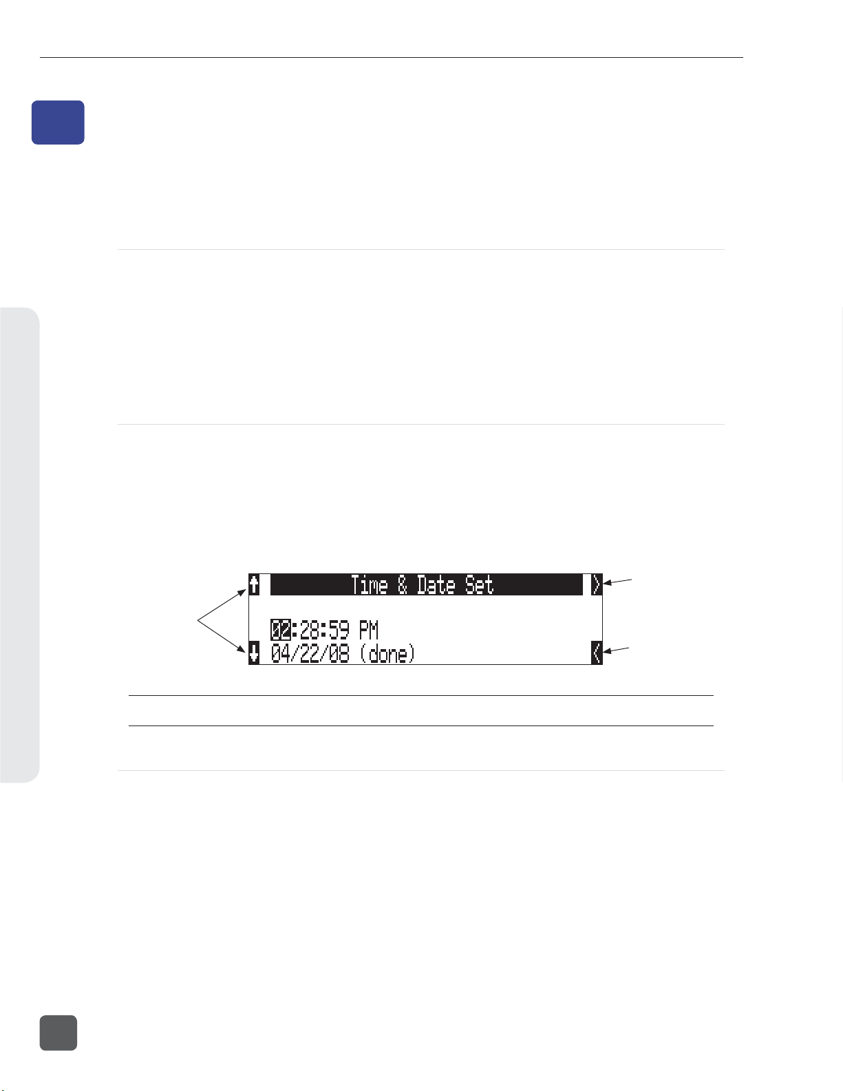
788T/788T-SSD User Guide and Technical Information
File Management and Storage8
8
File Management and Storage
The 788T, like a computer, saves audio recordings to a fi le system containing fi les and folders. The
788T/788T-SSD formats its internal drive, CompactFlash cards, and attached external drives in the
FAT32 format as single drives named “788T INDD”, “788T CF”, and “788T EXTHDD ,” respectively.
Automatic File Splitting
While it is possible to have thousands of fi les on the 788T storage volume(s), the largest any single
fi le may be is 4 GB. See Appendix D – FAT32 and Maximum File Size. The 788T automatically splits an
audio fi le before the 4 GB size is reached (2 GB is factory default) and begins writing to a new fi le.
When joined in an editing program, these fi les match seamlessly with no samples lost. Maximum
File Size can be selected in the Setup Menu option FILE: MAX SIZE of 512 MB, 1 GB, 2 GB, and 4
GB. The 512 MB size allows the user to break an audio program into CD-R sized fi les for backup to
inexpensive CD-R media. There is also a selection of sizes to ensure that recorded fi les will fi t onto
common CompactFlash card capacities.
File Time and Date
Similar to a computer fi le system, all fi les recorded by the 788T are stamped with the creation time
and date. To ensure that accurate time-of-day and fi le generation dates are written for each fi le, make
certain that the time-of-day clock and calendar are correct.
File time and date and time code are unrelated.
1. Enter the Setup Menu option TIME/DATE: SET.
2. Set the current time and date using the navigation below.
advances to the
soft keys increment
and decrement
time and date,
controller can be
turned, as well
Once set, the time and date clock will be maintained indefi nitely.
next selection
returns to the
previous selection
Folder Actions
All fi les generated by the 788T can be saved to the Root directory, a Project Folder, a Daily (Roll)
Folder, or a Scene Folder (Files are saved to the Root directory by default). File organization is
managed in the Setup Menu option FILE: FOLDER O PTION S . Folder choices include TOP -LEVEL,
MID- LEVEL, and BOTT OM LEVEL FOLD ERS . Folders are created when the record key is pressed. This
reduces the likelihood of empty folders.
• Top-Level / Project Folder – is a root-level folder and can be set with a user-selected Project
name. Use this, for instance, as the name of the movie you are working on. The name of this
folder is inserted in the <PROJECT> fi eld of the iXML and bEXT chunks. See Appendix 2 –
Metadata Implementation.
The Top-Level folder can also be de-activated by selecting <NONE> from the Setup Menu. If the
Top-Level folder is not used then the next lower-level folder will reside at the drive’s root. If
the TOP-LEVEL folder is active then the MID-LEVEL and BOTTOM-LEVEL folders will be its sub-
folders.
84
v. 3.02 Features and specifications are subject to change. Visit www.sounddevices.com for the latest documentation.
Page 93

788T/788T-SSD User Guide and Technical Information
• Mid-Level / Tape (Roll) Folder – can be selected as a Roll folder with user-selected name or as
a <DAILY> folder, or not used. The name of this folder is inserted in the <TAPE> (Roll) fi eld of
the iXML and bEXT chunks.
If a TOP-LEVEL folder is in use, the MID-LEVEL folder will be a sub-folder of the TOP- LEVEL
folder. If no TOP- LEVEL folder is used, the MID- LEVEL folder will reside at the drive’s root. If
set to <DAILY> a new folder will be created daily. When recording past midnight the 788T will
prompt to make to a new daily folder.
• Bottom-Level / Scene Folder – can be selected as a <SCENE> folder which will use the name
generated from the REC: SCENE NAME/NUMBER Setup Menu, as a user-selected name, or not
used at all.
If no upper-level folder is in use, the BOTTOM- LEVEL folder will reside at drive’s root. If the
MID- LEVEL and/or TOP-LEVEL are in use the BOTTOM- LEVEL folder will be a sub-folder.
Example: If a daily Folder is desired, set the TOP-LEVEL to <NONE> , the MI D-LEVEL folder to
<DAIL Y>, and the BOTTOM-LEVEL to <NONE>. This will generate a Daily Folder in the root directory
with fi les directly inside the folder.
A hierarchical view of fi les generated by the 788T is below.
788T
FALSETAKES
SOUNDDEV
TRASH
TOP-LEVEL
Example:
NAMET01.WAV
NAMET02.WAV
MID-LEVEL
BOTTOM-LEVEL
788T
FALSETAKES
SOUNDDEV
TRASH
PROJECT
07Y01M15
SCENE
The FALSETAKES, SOUNDDEV, and TRASH folders are automatically
generated. SOUNDDEV is not viewable from the 788T File Viewer.
A TOP-LEVEL folder sits in the root directory. This folder can be
negated by choosing <None> in the menu File: Folder Options.
A MID-LEVEL folder can be used as a sub-folder. This folder can be
selected to be a <Daily> folder in the menu File: Folder Options.
A BOTTOM-LEVEL folder could also be used as a sub-folder. This
folder can be selected to be a <Scene> folder in the menu File: Folder
Options.
This is a TOP-LEVEL folder named PROJECT activated in the menu
File: Folder Options.
This is a MID-LEVEL folder set to <Daily> from the menu File: Folder
Options.
This is a BOTTOM-LEVEL folder set to <Scene> from the menu
File: Folder Options.
These two files are title NAME in the menu
Rec: Scene Name/Number.
The Drive Directory (File Viewer)
File Management and Storage8
From within the Drive Directory, navigate between storage media, folders, and fi les. View fi le properties and select fi les for playback. The Drive Directory always exits to the main LCD display whether entered from the Setup Menu or via the Take List.
The left side of the File Viewer displays storage media, folders, and fi les. The top line displays the directory path in the form of DRIVE\FOLDER NAME and the right side displays fi le or folder proper-
85
Page 94

788T/788T-SSD User Guide and Technical Information
ties depending on what is selected on the left hand side. File and folder names are listed in the order
in which they were recorded.
Navigation
Moving from fi le to fi le is similar to navigating among fi les on a computer. To access the Drive Directory perform the following:
1. From the Main screen, press the HDD key to access the Take List.
File Management and Storage8
2. Press the soft DRV (HDD) key to access the Drive Directory. The Drive Directory will open
immediately to the location of the last take recorded or played back. Note: For quick access to
the Drive Directory from the Main Screen, simply press the HDD key twice.
3. Use the Rotary Switch to scroll through fi les and folders. Select “\..” at the top of the list to
move up one menu level. For quick access to the Root Directory press the soft
(MENU) key.
86
4. Select either HDD, CF or EXT and scroll down through the directory to the required fi le.
Should CF or EXT not be connected, the media will be crossed out in the media select screen.
Larger fi les on slower media can take longer to display details; this is normal.
Unrecognized File types do not appear in the fi le viewer, although all folders are viewable.
v. 3.02 Features and specifications are subject to change. Visit www.sounddevices.com for the latest documentation.
Page 95

788T/788T-SSD User Guide and Technical Information
Selecting Files for Playback
Enter the Drive Directory and navigate to the desired fi le for playback. Once the desired fi le
is highlighted, press play. The 788T will playback according to what has been selected in the
PLAY : AUTOPLAY MODE Setup Menu option. If a monophonic fi le is selected, the 788T will playback
all associated monophonic fi les from the same take simultaneously. See Playback.
Folder Options Menu
The Folder Options Menu is accessed by pressing the soft OPTIONS (FAST FORWARD) key for
any folder in the Drive Directory. Here it is possible to rename folders, set and clear copy fl ags, and
delete folders.
Operations performed within the Drive Directory Folder Options Menu are only applied to the select
media, as defi ned in the directory path. To apply edits across all available media, operations must be
performed within the Take List. See Take Edit Menu.
Rename Folders
Folder names can be edited after recording has taken place. To rename a folder:
1. Enter the Drive Directory.
2. Highlight the desired folder to be renamed.
3. Press the soft OPTIONS (FAST FORWARD) key to access the Folder Options Menu..
4. Select Rename.
5. Rename the folder and press the soft Check Mark (TONE) key to save the new fi le name
Set and Clear Copy Flags
Copy Flags are useful for selecting various takes to be copied from one media to another. By
default, Takes recorded by the 788T have their Copy Flag set to On. If the Setup Menu option
FILE: COPY FLAG RESET is enabled the Copy Flags will automatically clear after the fi le has been
copied from one media to another. See File Copying Among Available Media. Setting and Clearing Flags
from the Folder Options menu only changes the Copy fl ag status on the select media. If changing the
fl ag status across all media is desired, perform the Set/Clr Copy Flag operation in the Take List.
To set or clear Copy Flags from the Drive Directory Folder Options Menu:
1. Select a media or folder in the Drive Directory.
2. Press the soft OPTIONS (FAST FORWARD) key, then choose Set Copy Flag or Clr Copy Flag
respectively. If the media or folder contains sub-folders, the 788T will display the following
prompt:
File Management and Storage8
Delete Folders
Any folder located on any of the storage media, can be deleted. Permanently deleting folders is a
two-step process. Similar to Mac OS and Windows operating systems, the 788T uses a “trash” folder
87
Page 96

788T/788T-SSD User Guide and Technical Information
to temporarily hold fi les which have been deleted. To send a folder and all of its contents to the trash,
perform the following:
1. Enter the Drive Directory.
2. Navigate to the folder to be deleted.
3. Press the soft OPTIONS (Fast Forward) key.
4. Select DELETE.
5. You will be prompted to confi rm folder deletion.
The fi le has now been moved to the select media’s trash folder and will no longer appear in the
Drive Directory. It will, however, appear in the trash folder. Files sent the trash folder can still be
viewed and played.
If a folder has accidentally been sent to the trash, the drive can be mounted to a computer via
FireWire/USB and moved back to its original folder. Folders moved to the trash cannot be removed
from the trash directly from the 788T.
File Management and Storage8
Folders deleted from the Folder Options Menu are only deleted from the select media, as defi ned in the
directory path. To Delete fi les across all available media, Delete must be performed within the Take List.
See Take Edit Menu for more details.
File Options Menu
The File Options Menu is accessed by pressing the soft OPTIONS (FAST FORWARD) key for any fi le
in the Drive Directory. User Settings can be recalled from any WAV fi le recorded by the 788T postfi rmware revision 2.18. See Saving and Recalling User Settings
Drive Directory Options Menu
All drive specifi c operations are performed in the Drive Directory Options Menu. The following
functions are performed within the Drive Directory Options Menu:
• Rename (the Drive/Folder)
• Set Copy Flags
• Clear Copy Flags
Perform the following steps to the access the Drive Directory Options Menu.
1. Access the Drive Directory and navigate to the Root Directory. See Navigation for additional
steps.
• Empty Trash (and False Takes)
• Erase (Formats the Drive)
88
2. Highlight the desired Drive.
v. 3.02 Features and specifications are subject to change. Visit www.sounddevices.com for the latest documentation.
Page 97

788T/788T-SSD User Guide and Technical Information
3. Press the soft Options (Fast Forward) key to access the Drive Directory Options Menu.
Set and Clear Copy Flags
Copy Flags are useful for selecting various takes to be copied from one media to another. By
default, Takes recorded by the 788T have their Copy Flag set to On. If the Setup Menu option
FILE: COPY FLAG RESET is enabled the Copy Flags will automatically clear after the fi le has been
copied from one media to another. See File Copying Among Available Media. Setting and Clearing Flags
from the Drive Options Menu changes the Copy fl ag status of all fi les on the select media. If changing the fl ag status for select takes is desired, perform the Set/Clr Copy Flag operation in the Take
List.
To set or clear Copy Flags from the Drive Options Menu:
1. Select a media or folder in the Drive Directory.
2. Press the soft OPTIONS (FAST FORWARD) key, then choose Set Copy Flag or Clr Copy Flag
respectively. If the media or folder contains sub-folders, the 788T will display the following
prompt:
Emptying the Trash
Files and folders that have been moved to the Trash or False Takes folders can be permanently
deleted from each media. Each drive has its own Trash folder and False Takes folder that are permanently deleted independently from the Drive Directory Options Menu.
File Management and Storage8
Once the trash folder has been emptied, any fi les or folders it contained are permanently deleted
and cannot be recovered. After the trash folder has been emptied, a prompt to empty the false takes
folder is displayed.
89
Page 98

788T/788T-SSD User Guide and Technical Information
Erase (Media Format)
For best operation periodic re-formatting of the 788T media is recommended. Formatting the internal
drive, Compact Flash, and external media rebuilds the FAT (fi le allocation table) and erases all audio
and data fi les present on the medium. Formatting media prevents fragmentation and reduces the
likelihood of directory corruption.
Be certain that all fi les on the drive have been backed up to another media before formatting. Once formatted, all data on the given media will be erased. Dynamic lists such as track names, scene names, folder
name entries, etc... will be saved.
To format the 788T media:
1. Ensure that all data on the drive has been copied or is no longer needed.
2. Press the HDD key to access the Take List.
3. Press the soft DRV (HDD) key to access the Drive Directory.
File Management and Storage8
4. Press the soft
5. Use the Rotary Switch to highlight the desired media to be forma ed.
(MENU) key to access the Root Directory.
6. Press the soft Options (Fast Forward) key to access the Drive Directory Options Menu.
7. Select the ERASE option from the list.
8. To verify that a non-recoverable format of the storage device is desired, two keys must be
pressed to begin forma ing. Press and hold down the PLAY key to enable the Check Mark.
Press and hold
down the PLAY key
90
v. 3.02 Features and specifications are subject to change. Visit www.sounddevices.com for the latest documentation.
Page 99

788T/788T-SSD User Guide and Technical Information
9. Press the soft Check Mark (TONE) key to begin forma ing.
Press the TONE key
to begin formatting
When the operation is complete, the 788T will generate a fresh menu hierarchy. Dynamic lists such
as track names, scene names, folder options, etc. will be saved.
Storage Media – Internal Drive
The 788T and 788T-SSD internal drive is the primary storage medium. The large capacity and fast
data read/write speeds of hard drives and solid state drives are a perfect choice when long form,
high data rate recording is performed. These drives offer a good balance of speed, reliability, noise
performance, and current draw.
The drive installed in the 788T is formatted at the factory as a single-partition FAT32 volume. If a
drive with multiple partitions is installed, the 788T will only “see” and address the primary partition.
788T Drive Type
The 788T ships with a 2.5-inch, 5400 RPM hard drive with a SATA interface. Sound Devices has
chosen the specifi c mechanism for vibration and shock resistance. Most 2.5 inch drives conforming to
the SATA specifi cation can be substituted for the factory hard drive. When choosing a substitute hard
drive, note that higher RPM hard drives draw more current, reducing battery run time. Higher speed
drives may be used with the 788T, however they will not signifi cantly improve performance. They
will slightly increase transfer throughput with the penalty of increased current draw and reduced
battery run time. The 788T can address drives with capacities up to 2 TB.
788T-SSD Drive Type
The 788T-SSD ships with an upgraded 2.5-inch Solid State Drive (SSD) with a SATA interface. Upgrading to an SSD further enhances the performance and reliability of the recorder. SSD mechanisms
allow for faster transfer speeds, ultra-quiet performance, and maximum vibration and shock resistance.
Drive Replacement
The internal drive can be removed and replaced if the device fails or if a different capacity drive is
needed. The internal drive is not intended to be a swappable, deliverable medium. Its SATA connector is not rated for repeated insertion and removal cycles.
File Management and Storage8
In typical service conditions Sound Devices recommends hard drive replacement once every three years.
91
Page 100

788T/788T-SSD User Guide and Technical Information
The internal drive is mounted to the bottom-side of the recorder’s chassis and is screwdriver accessible. The drive is “suspended” in the unit with a shock absorbing foam and is attached to the main
circuit board via a “fl ex board”. Since the high-density circuitry and tight construction require specific electronics knowledge, Sound Devices strongly recommends drive replacement be performed by a
qualifi ed technician using proper ESD precautions. Drive replacement done by a qualifi ed technician
has no warranty implications.
File Management and Storage8
788T with bottom panel
removed showing drive
mounting location
Storage Medium – Removable CompactFlash
CompactFlash (CF) is a practical, portable storage media for audio recording. Its speed, capacity, and
price continue to evolve to the benefi t of portable recorders. The 788T can write to and read from CF
cards as either its sole storage media or simultaneously with the internal drive.
When to Use CF
The key benefi ts of CompactFlash include:
• wider temperature range capability than hard drives
• greatly increased shock immunity versus hard drives
• convenient, portable, removable media
• ubiquitous card readers and transfer tools
• more power effi cient than hard drives and solid state drives
Formatting
Upon insertion of an unformatted (or non-FAT32 formatted) CF card, the 788T will prompt the user
to format the card. If the card is formatted as a FAT32 volume, the card will be ready to be selected.
To reformat the CF media see Erase (Media Formatting) in the Drive Directory Options Menu. The 788T can
format and use CompactFlash cards with capacities of 128 MB and greater.
92
Formatting the CF rebuilds the FAT (fi le allocation table) and erases all audio and data fi les present
on the card. While some PC and Mac utilities can recover fi les immediately after formatting a CF
v. 3.02 Features and specifications are subject to change. Visit www.sounddevices.com for the latest documentation.
 Loading...