

Sony XR-C5120RA Service manual
XR-C5120RA
SERVICE MANUAL
SPECIFICATIONS
Cassette player section
Tape track 4-track 2-channel stereo
Wow and flutter 0.08 % (WRMS)
Frequency response 30 – 18,000 Hz
Signal-to-noise ratio
Cassette type
TYPE II, IV 61 dB
TYPE I 58 dB
Tuner section
FM
Tuning range 87.5 – 108.0 MHz
Aerial terminal External aerial connector
Intermediate frequency 10.7 MHz
Usable sensitivity 9 dBf
Selectivity 75 dB at 400 kHz
Signal-to-noise ratio 65 dB (stereo),
Harmonic distortion at 1 kHz
Separation 35 dB at 1 kHz
Frequency response 30 – 15,000 Hz
MW/LW
Tuning range MW: 531 – 1,602 kHz
Aerial terminal External aerial connector
Intermediate frequency 10.7 MHz/450 kHz
Sensitivity MW: 30 µV
68 dB (mono)
0.7 % (stereo),
0.4 % (mono)
LW: 153 – 281 kHz
LW: 50 µV
AEP Model
Model Name Using Similar Mechanism XR-C5100R
Tape Transport Mechanism Type MG-25G-136
Power amplifier section
Outputs Speaker outputs
Speaker impedance 4 – 8 ohms
Maximum power output 40 W × 4 (at 4 ohms)
General
Outputs Audio output
Tone controls Bass ±8 dB at 100 Hz
Power requirements 12 V DC car battery
Dimensions Approx. 188 × 58 × 181 mm
Mounting dimensions Approx. 182 × 53 × 164 mm
Mass Approx. 1.2 kg
Supplied accessories
Design and specifications are subject to change
without notice.
(sure seal connectors)
Power aerial relay control
lead
Power amplifier control
lead
Telephone ATT control
lead
Treble ±8 dB at 10 kHz
(negative earth)
(w/h/d)
(w/h/d)
Parts for installation and
connections (1 set)
Front panel case (1)
UK Model
MICROFILM
FM/MW/LW CASSETTE CAR STEREO

TABLE OF CONTENTS
1. GENERAL
Location of controls ........................................................ 3
Resetting the unit ............................................................ 3
Detaching the front panel................................................ 3
Setting the clock.............................................................. 3
2. DISASSEMBLY ......................................................... 4
3. ASSEMBLY OF MECHANISM DECK........... 5
4. MECHANICAL ADJUSTMENTS ....................... 8
5. ELECTRICAL ADJUSTMENTS......................... 8
6. DIAGRAMS
6-1. Block Diagram – TUNER Section – .............................. 12
6-2. Block Diagram – TAPE/MAIN Section – ...................... 13
6-3. Block Diagram – DISPLAY/
KEY CONTROL/BUS CONTROL/
POWER SUPPLY Section – ........................................... 14
6-4. Note for Printed Wiring Boards and
Schematic Diagrams ....................................................... 15
6-5. Printed Wiring Board
– MAIN Board (Component Side) – .............................. 16
6-6. Printed Wiring Board
– MAIN Board (Conductor Side) – ................................ 17
6-7. Schematic Diagram – MAIN Board (1/2) – ................... 18
6-8. Schematic Diagram – MAIN Board (2/2) – ................... 19
6-9. Printed Wiring Board – KEY Board –........................... 20
6-10. Schematic Diagram – KEY Board – ............................. 21
6-11. IC Pin Function Description ........................................... 24
Flexible Circuit Board Repairing
• Keep the temperature of the soldering iron around 270 ˚C during repairing.
• Do not touch the soldering iron on the same conductor of the
circuit board (within 3 times).
• Be careful not to apply force on the conductor when soldering
or unsoldering.
Notes on chip component replacement
• Never reuse a disconnected chip component.
• Notice that the minus side of a tantalum capacitor may be damaged by heat.
7. EXPLODED VIEWS................................................ 28
8. ELECTRICAL PARTS LIST ............................... 31
2
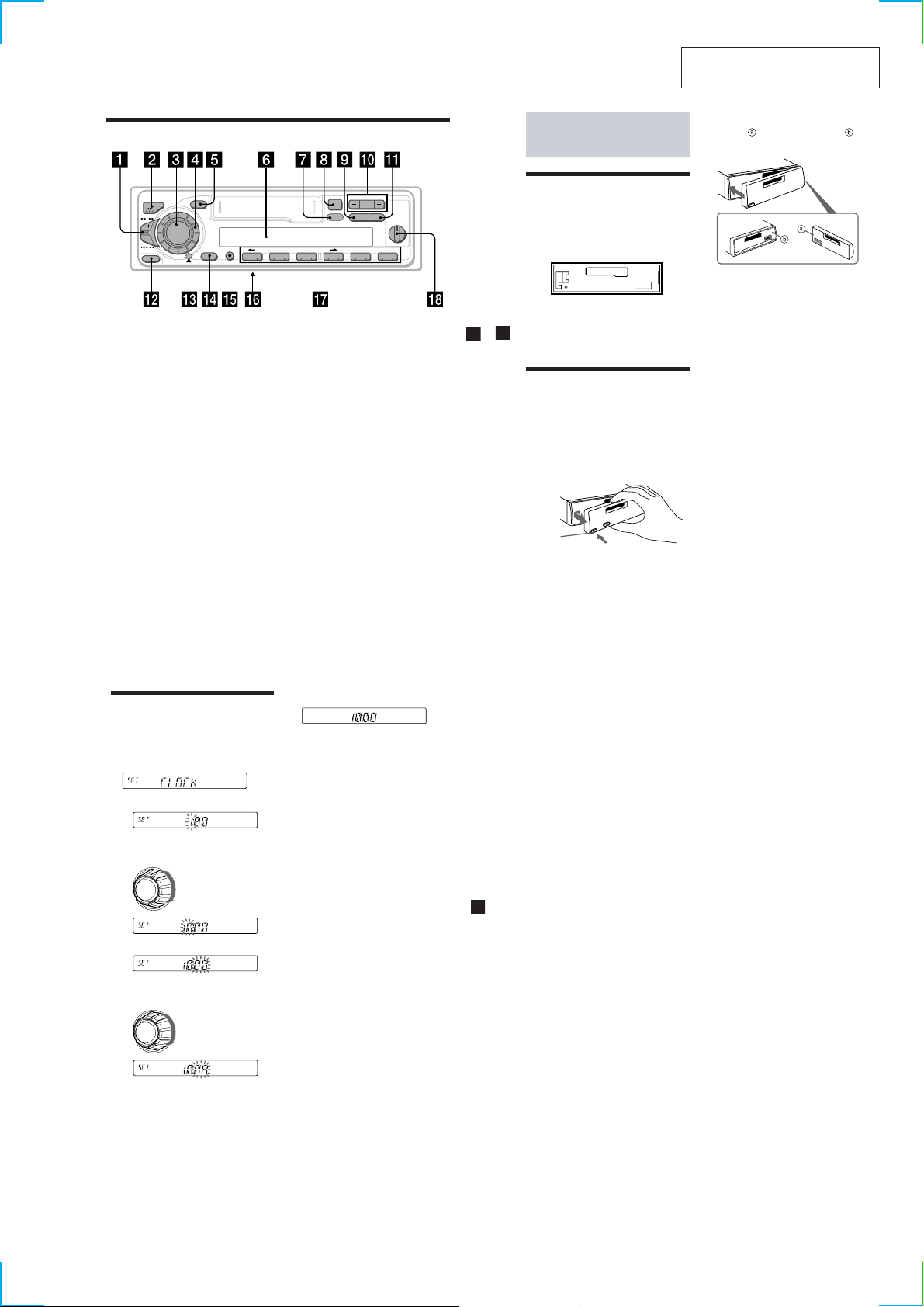
Location of controls
SECTION 1
GENERAL
Getting Started
This section is extracted from
instruction manual.
Attaching the front panel
Attach part of the front panel to part of
the unit as illustrated and push the left side
into position until it clicks.
SOURCE
SOUND
OFF
SHIFT SET UP
MODE
SEEK / AMS
RELEASE
Refer to the pages listed for details.
1 SEEK/AMS (seek/Automatic Music
Sensor/manual search) control
6, 8, 10, 13, 19
2 MODE (o)button
During tape playback:
Playback direction change 6
During radio reception:
BAND select 7, 8
During CD or MD playback:
CD/MD unit select 18
3 SOURCE (TAPE/TUNER/CD/MD) button
6, 7, 8, 11, 18
4 Dial (volume/bass/treble/left-right/rear-
front control) 5, 16
5 SOUND button 16
6 Display window
7 DSPL (display mode change) button
6, 8, 9, 18
8 Z (eject) button 6
9 PTY button
RDS Programme 13
+
PRESET
–
DISC
Z
PLAY MODE
0… PRESET/DISC button
During radio reception:
Preset stations select 8
During CD/MD playback:
Disc change 19
qa` AF/TA button
9, 10, 11, 12
qs“ RELEASE (front panel release) button
4, 21
qd Reset button (located on the front side
of the unit behind the front panel) 4
qf OFF button 4, 6
qg SHIFT button
PLAY MODE 7, 8, 10, 12, 19
SET UP 5, 13, 16, 18
qh POWER SELECT switch
(located on the bottom of the unit)
See “POWER SELECT switch” in the
Installation/Connections manual.
qj Number buttons 8, 10, 12
qk D-BASS control 17
D-BASS
AF/TAPTYDSPL
1
2
OFF
3
564321
Resetting the unit
Before operating the unit for the first time or
after replacing the car battery, you must reset
the unit.
Remove the front panel and press the reset
button with a pointed object, such as a
ballpoint pen.
Reset button
Note
Pressing the reset button will erase the clock
setting and some memorized functions.
Detaching the front panel
You can detach the front panel of this unit to
protect the unit from being stolen.
1
Press (OFF).
2
Press (RELEASE), then slide the front
panel a little to the left, and pull it off
towards you.
(RELEASE)
Notes
• Be sure not to drop the panel when detaching it
from the unit.
• If you detach the panel while the unit is still
turned on, the power will turn off automatically
to prevent the speakers from being damaged.
• When carrying the front panel with you, use the
supplied front panel case.
(OFF)
Notes
• Be sure not to attach the front panel upside
down.
• Do not press the front panel too hard against the
unit when attaching it.
• Do not press too hard or put excessive pressure
on the display window of the front panel.
• Do not expose the front panel to direct sunlight
or heat sources such as hot air ducts, and do not
leave it in a humid place. Never leave it on the
dashboard of a car parked in direct sunlight or
where there may be a considerable rise in
temperature.
Caution alarm
If you turn the ignition key switch to the OFF
position without removing the front panel, the
caution alarm will beep for a few seconds
(only when the POWER SELECT switch on the
bottom of the unit is set to the A position).
If you connect an optional power amplifier and
do not use the built-in amplifier, the beep
sound will be deactivated.
Setting the clock
The clock uses a 24-hour digital indication.
Example: To set the clock to 10:08
1
Press (SHIFT), then press (2) (SET UP)
repeatedly until “CLOCK” appears.
1 Press (4) (t).
The hour indication flashes.
2 Set the hour.
to go backward
to go forward
3 Press (4) (t).
The minute indication flashes.
4 Set the minute.
to go backward
to go forward
2
Press (SHIFT).
The clock starts.
3
Press (SHIFT).
After the clock setting is complete, the
display returns to normal playback mode.
Note
If the POWER SELECT switch on the bottom of the
unit is set to the B position, turn the power on
first, then set the clock.
3
4
5
3
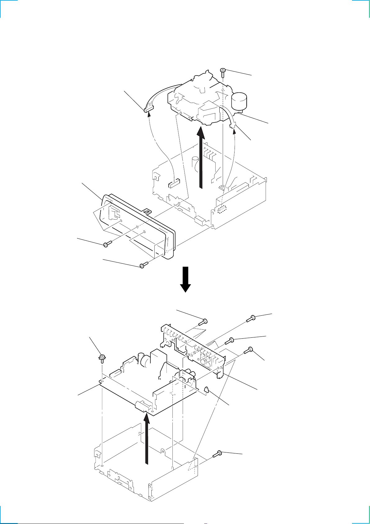
SECTION 2
k
DISASSEMBLY
Note: Follow the disassembly procedure in the numerical order given.
SUB PANEL, MECHANISM DECK (MG-25G-136)
3
connector
(CN302)
2
sub panel
5
screw
(PTT2.6
6
4
flexible flat cable
(CN301)
×
6)
mechanism dec
(MG-25G-136)
1
three screws
(PTT2.6
×
8)
1
three screws
(PTT2.6
×
MAIN BOARD, HEAT SINK
3
two ground point
screws
4
main board
8)
5
three screws
(PTT2.6
×
8)
2
rubber cap (25)
5
7
heat sink
1
screw
(PTT2.6
6
three screws
(PTT2.6
two screws
(PTT2.6
×
8)
×
12)
×
8)
1
two screws
(PTT2.6
×
8)
4
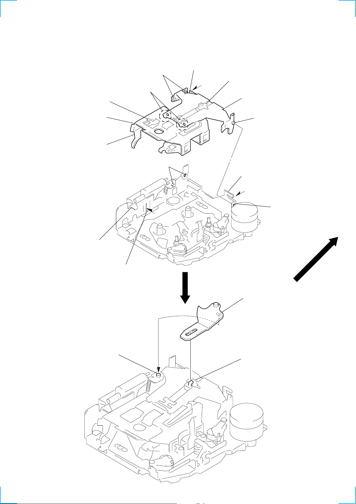
SECTION 3
2
Move the arm (suction) in the arrow
direction and fit on projection.
1
Fit the arm (suction) on the shaft.
projection
ASSEMBLY OF MECHANISM DECK
Note: Follow the assembly procedure in the numerical order given.
HOUSING
5
Fit projection on C part.
2
Install the hanger onto
two claws of the housing.
4
Fit claw on B part.
3
Put the housing
under
A
part.
housing
C
part
7
Holder the hanger by bending the claw.
1
Install the catch to the hanger.
hanger
6
Fit projection on D part.
8
Hold the hanger by
bending the claw.
ARM (SUCTION)
A
part
B
part
D
part
5
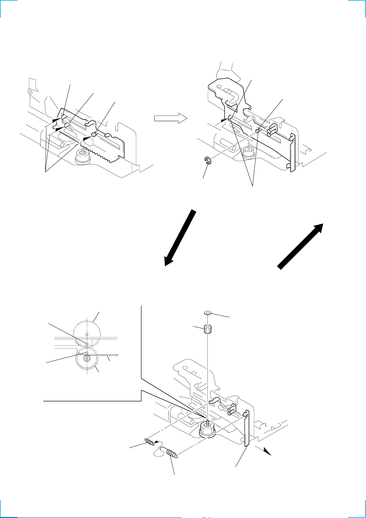
LEVER (LDG-A) / (LDG-B)
)
shaft
A
shaft
1
Fit the lever (LDG-A) on
shafts A – C and install it.
B
shaft
C
3
type-E stop ring 2.0
shaft
A
Fit the lever (LDG-B) on
2
shafts
install it.
A
and B and
shaft
B
GEAR (LDG-FT)
hole
hole
4
gear (LDG-D)
lever (LDG-A)
gear (LDG-FB)
Align hole in the gear (LDG-D)
with hole the lever (LDG-A).
2
tension spring (LD-2)
5
gear (LDG-FT)
1
6
polyethylene washer
3
Move the lever (LDG-B
2
tension spring (LD-1)
6
in the arrow direction.
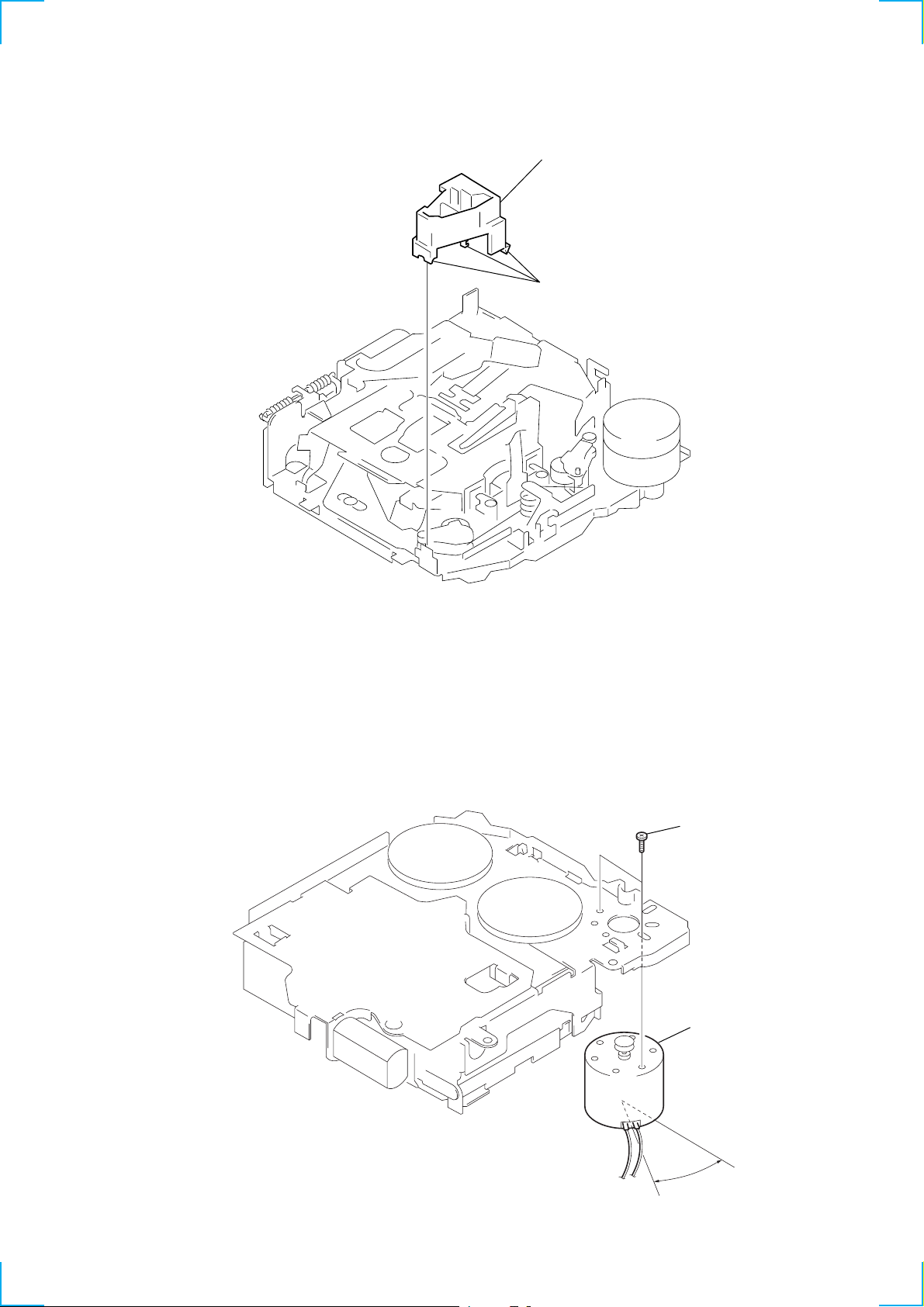
GUIDE (C)
2
guide (C)
1
three claws
MOUNTING POSITION OF CAPSTAN/REEL MOTOR (M901)
two precision screws
×
2)
(P2
capstan/reel motor
(M901)
30˚
7
SECTION 4
r
MECHANICAL ADJUSTMENTS
SECTION 5
ELECTRICAL ADJUSTMENTS
1. Clean the following parts with a denatured-alcohol-moistened
swab:
playback head pinch roller
rubber belt capstan
idler
2. Demagnetize the playback head with a head demagnetizer.
3. Do not use a magnetized screwdriver for the adjustments.
4. After the adjustments, apply suitable locking compound to the
parts adjusted.
5. The adjustments should be performed with the power supply
voltage unless otherwise noted.
• Tor que Measurement
Mode Torque Meter Meter Reading
Forward CQ-102C
Forward
Back Tension (0.01 – 0.06 oz•inch)
Reverse CQ-102RC
Reverse
Back Tension (0.01 – 0.06 oz•inch)
FF, REW CQ-201B
CQ-102C
CQ-102RC
30 – 65 g•cm
(0.42 – 0.90 oz•inch)
0.5 – 4.5g•cm
30 – 65 g•cm
(0.42 – 0.90 oz•inch)
0.5 – 4.5g•cm
60 – 200 g•cm
(0.83 – 2.78 oz•inch)
• Tape T ension Measurement
Mode Tension Meter Meter Reading
Forward CQ-403A
Reverse CQ-403R
more than 90 g
(more than 3.18 oz)
more than 90 g
(more than 3.18 oz)
TEST MODE
This set have the test mode function. In the test mode, FM Auto
Scan/Stop Level and AM (MW) Auto Scan/Stop Level adjustments
can be performed easier than it in ordinary procedure.
<Set the Test Mode>
1. Set the “power select” switch (S501) is “A (ON)” position.
2. Turn ON the regulated power supply. (All LEDs on the set
lights up, and the clock is displayed.)
Note: Press the [OFF] button, if the clock is not displayed.
3. Push the preset [4] button.
4. Push the preset [5] button.
5. Press the preset [1] button for more than two seconds.
6. Then the display indicates all lights, the test mode is set.
<Release the Test mode>
1. Push the [OFF] button.
2. Return the “power select” switch (S501) to initially set position.
See the adjustment location from on page 11 for the
adjustment.
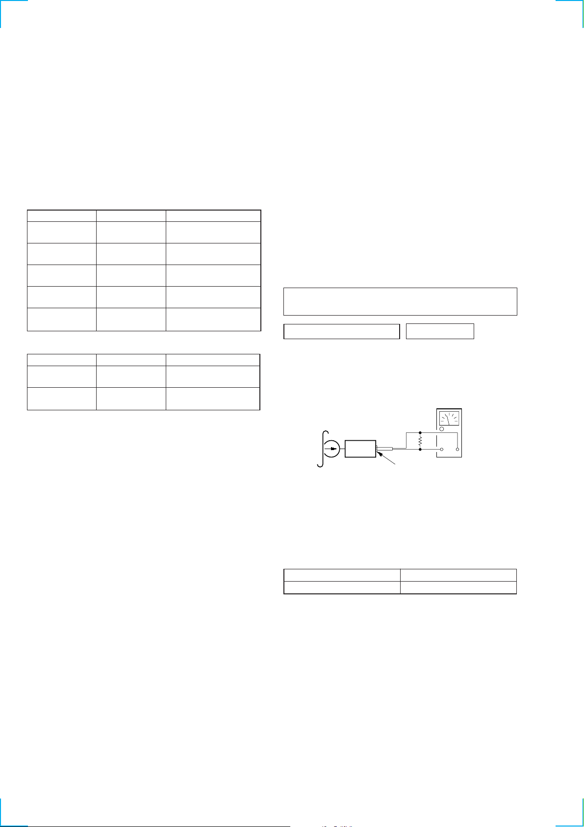
TAPE DECK SECTION
0 dB=0.775 V
Tape Speed Adjustment
Setting:
speed checker
or
test tape
WS-48A
(3 kHz, 0 dB)
frequency counte
10 k
Ω
set
AUDIO OUT jack (CNJ151)
+–
Procedure:
1. Put the set into the FWD PB mode.
2. Adjust adjustment resistor for inside capstan motor so that the
reading on the speed checker or frequency counter becomes in
specification.
Specification: Constant speed
Speed checker Frequency counter
–1.5 to +2.5% 2,955 to 3,075 Hz
Adjustment Location: See page 11.
8
TUNER SECTION
0 dB=1 µV
Cautions during repair
When the tuner unit is defective, replace it by a new one because its internal block is difficult to repair.
Note:
Adjust the tuner section in the sequence shown below.
1. FM Auto Scan/Stop Level Adjustment
2. FM Stereo Separation Adjustment
3. FM RDS S Meter Adjustment
4. MW Auto Scan/Stop Level Adjustment
FM Auto Scan/Stop Level Adjustment
Setting:
[SOURCE] button: FM
FM RF signal
generator
Carrier frequency : 98.0 MHz
Output level : 22 dB (12.6
Mode : mono
Modulation : 1 kHz, 22.5 kHz deviation (30%)
Procedure:
1. Set to the test mode. (See page 8)
2. Push the [SOURCE] button and set to FM.
antenna jack (J1)
0.01 µF
Display
set
µ
V)
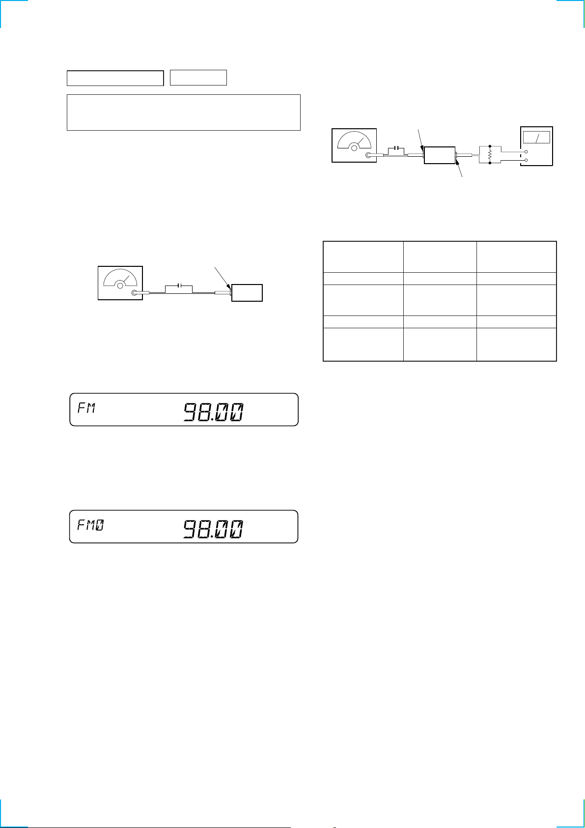
FM Stereo Separation Adjustment
Setting:
[SOURCE] button: FM
FM RF signal
generator
Carrier frequency : 98.0 MHz
Output level : 70 dB (3.2 mV)
Mode : stereo
Modulation : main: 1 kHz, 20 kHz deviation (26.7%)
antenna jack (J1)
0.01 µF
set
sub: 1 kHz, 20 kHz deviation (26.7%)
: 19 kHz pilot: 7.5 kHz deviation (10%)
10 k
AUDIO OUT jack (CNJ151)
Procedure:
FM Stereo
signal generator
output channel
L-CH L-CH A
R-CH L-CH Adjust RV4 on TU1
R-CH R-CH C
L-CH R-CH Adjust RV4 on TU1
Level meter Level meter
connection reading (dB)
for minimum reading.
for minimum reading.
L-CH Stereo separation: A-B
R-CH Stereo separation: C-D
The separations of both channels should be equal.
level meter
Ω
B
D
+
–
SHUF
3. Adjust with the v olume RV2 on TU1 so that the “FM” indication turns to “FM0” indication on the display window.
But, in case of already indicated “FM0”, turn the RV2 so that
put out light “0” indication and adjustment.
Display
SHUF
Adjustment Location: See page 11.
Specification: Separation more than 30 dB
Adjustment Location: See page 11.
9
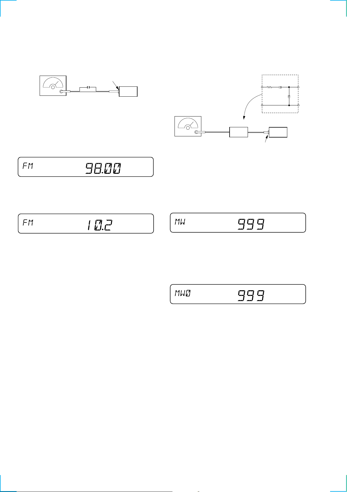
FM RDS S Meter Adjustment
(
)
Setting:
[SOURCE] button: FM
FM RF signal
generator
Carrier frequency : 98.00 MHz
Output level : 35 dB (56.2
Mode : mono
Modulation : no modulation
Procedure:
1. Set to the test mode. (See page 8)
2. Push the [SOURCE] button and set to FM.
3. Push the [6] button.
4. Adjust RV1 so that the display indication is “10.2”.
0.01 µF
Display
antenna jack (J1)
set
µ
V)
SHUF
MW Auto Scan/Stop Level Adjustment
Make this adjustment after “FM Auto Scan/Stop Level Adjustment”.
Setting:
[SOURCE] button: MW
30
Ω
15 pF
65 pF
AM RF signal
generator
AM dummy antenna
(50 Ω)
Carrier frequency : 999 kHz
30% amplitude
modulation by
1 kHz signal
Output level : 33 dB
44.7 µV
Procedure:
1. Set to the test mode. (See page 8)
2. Push the
[SOURCE] button and set to FM.
3. Push the [MODE] button and set to MW.
set
antenna jack (J1)
Display
Specification: Display indication: 10.0 to 10.4
Adjustment Location: See page 11.
SHUF
Display
TP SHUF
4. Adjust with the volume RV1 on TU1 so that the “MW” indication turns to “MW0” indication on the display window.
But, in case of already indicated “MW0”, turn the R V1 so that
put out light “0” indication and adjustment.
Display
TP SHUF
Adjustment Location: See page 11.
10

Adjustment Location:
t
– SET UPPER VIEW –
Tape Speed Adjustment
TU1
RV1 MW Auto Scan/Stop Level Adjustmen
RV2 FM Auto Scan/Stop Level Adjustment
RV4 FM Stereo Separation Adjustment
RV1 FM RDS S Meter Adjustment
1111
 Loading...