

Sony STR-DG600 Owner’s Manual
Multi Channel AV
Receiver
Operating Instructions
Owner's Record
The model and serial numbers are located on the rear of the unit. Record the
serial number in the space provkted below. Refer to them whenever you call
upon your Sony dealer regarding this product.
Model No. Serial No.
STR-DG600
©2006 Sony Corporation

To reduce the risk of fire or electric
shock, do not expose this apparatus to
rain or moisture.
To prevent fire, do not cover tile ventilation of the
apparatus with newspapers, table-cloths, curtains.
etc. And don't place lighted candles on the
apparatus.
To prevent fire or shock hazard, do not place objects
filled with liquids, such as vases, on the apparatus.
Do not inslall the appliance in a confined space.such as a bookcase or built-in cabinet.
general house waste: dispose of
_@ Don'l throw away batteries wilh
them correclly as chemical waste.
For customers in the United
States
WARNING
This equipment has been tested and lkmnd to comply
with the limits for a (!lass B digital device, pursuant
to Part 15 of the FCC Rules. These limits are
designed to provide reasonable protection against
harmful interference in a residential installation.
This equipment generates, uses. and can radiate
radio frequency energy and. if not installed and used
in accordance with the instructions, may cause
harmful interference to radio communications.
However: there is no guarantee that interference will
not occur in a particular installation. If this
equipment does cause harmful interference to radio
or television reception, which can be determined by
turning the equipment off and on. the user is
encouraged to try to correct the interference by one
or more of the following measures:
Reorient or relocate the receiving antenna.
Increase the separation between the equipment
and receiver.
Connect the equipment into an outlet on a circuit
different from that to which the receiver is
connected.
Consult the dealer or an experienced radio/TV
technician for help.
CAUTION
You are cautioned that any changes or modification
not expressly approved in this manual could void
your authority to operate this equipment.
2 US
This symbol is intended to alert the
user to the presence of uninsulated
"dangerous voltage" within the
product's enclosure that may be of
sufficient magnitude to constitute a
risk of electric shock to persons.
This symbol is intended to alert the
user to the presence of important
operating and maintenance
(servicing) instructions in the
literature accompanying the
appliance.
Note to CATV system installer:
This reminder is provided to call CATV system
installer's attention to Article 820-40 of the NEC
that provides guidelines for proper grounding and. in
particular, specifies that the cable ground shall be
connected to the grounding system of the building,
as close to the point of cable entry as practicah
About This Manual
• Tile instructions in this manual are for model
STR-DG600. Check your model number by
looking at tile lower right corner of tile front paneh
In this manuah models of area code U is used for
illustration purposes unless stated otherwise. Any
difference in operation is clearly iudicated in tile
text. for example. "Models of area code CA only".
• Tile instructions in this manual describe the
controls on the supplied remote. You carl also use
the controls on the receiver if they have tile same
or similar names as those on tile remote.
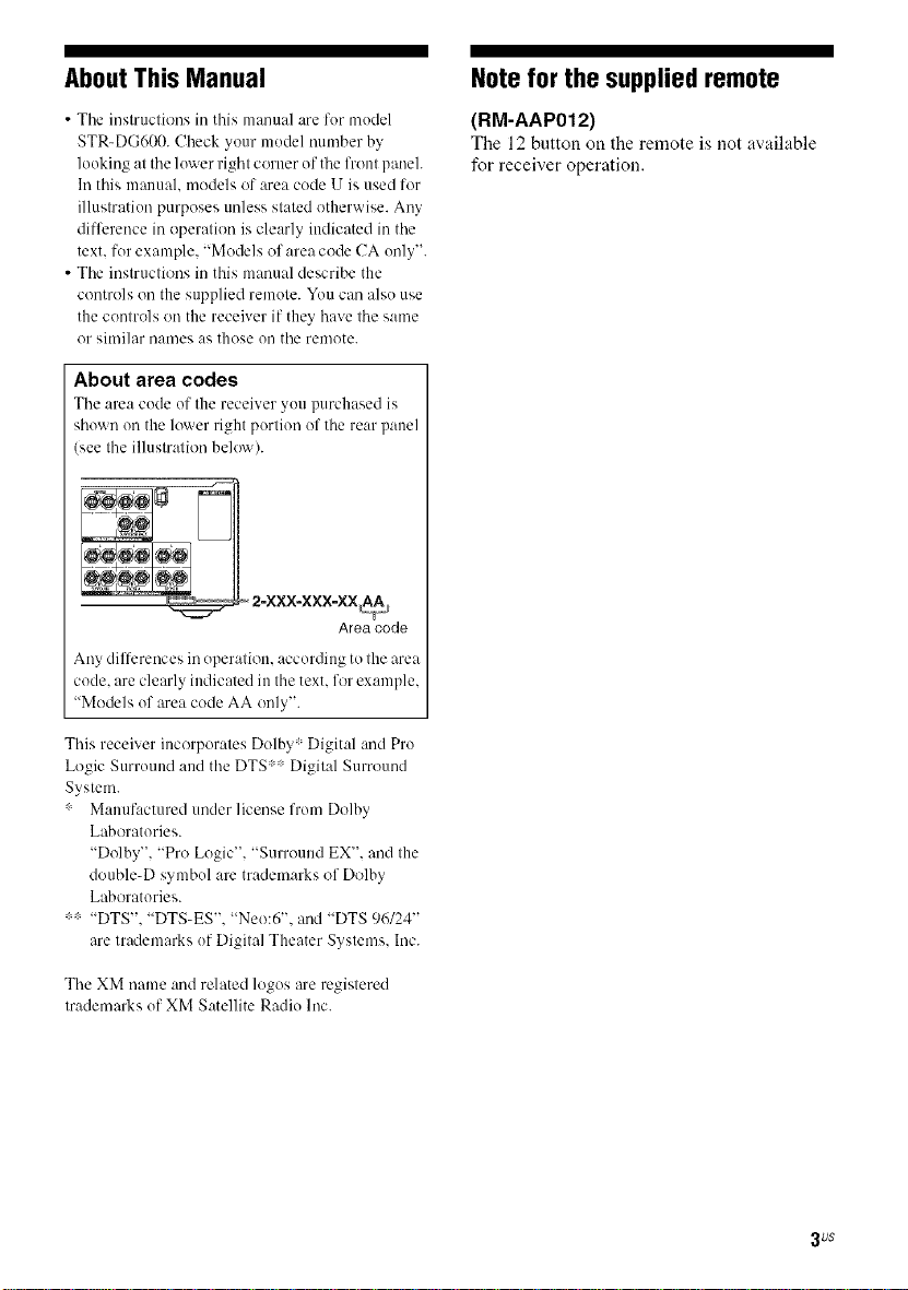
About area codes
The area code of the receiver you purchased is
shown on the lower right portion of tile rear panel
(see tile illustration belo'_x).
Area code
Any dilTcrences in operation, according to the area
code. are clearly indicated in the text. for example,
"Models of area code AA only".
Note for the supplied remote
(RM-AAP012)
The 12 button on the remote is not available
for receiver operation.
This receiver incorporates Dolby :Digital and Pro
Logic Surround and the DTS:: Digital Surround
System.
: Manufactured under license from Dolby
Laboratories.
"Dolby", "Pro Logic". "Surround EX". and the
double-D symbol are trademarks of Dolby
Laboratories.
"DTS", "DTS-ES", "Neo:6", and "DTS 96/24"
are trademarks of Digital Theater Systems. Inc.
The XM uame and related logos are registered
trademarks of XM Satellite Radio Inc.
3 uS
Tableof Contents
Getting Started
Description and location of parts ................... 5
1: Installing speakers ................................... 15
2: Connecting speakers ................................ 16
3a: Connecting the audio components ......... 17
3b: Connecting the video components ........ 22
4: Connecting the antennas .......................... 29
5: Preparing the receiver and the remote .....30
6: Selecting the speaker system ................... 32
7: Calibrating the appropriate settings
automatically
(AUTO CALIBRATION) ....................... 32
8: Adjusting the speaker levels and
balance
(TEST TONE) ........................................ 36
Playback
Selecting a component ................................. 37
Listening/Watching a component ................ 38
Amplifier Operations
Na'Jgating through menus ........................... 40
Adjusting the level (LEVEL menu) ............. 44
Adjusting the equalizer (EQ menu) ............. 45
Settings for the surround sound
(SUR menu) ............................................ 45
Settings for the tuner (TUNER menu) ......... 47
Settings for the audio (AUDIO menu) ......... 48
Settings for the video (VIDEO menu) ......... 49
Settings for the system (SYSTEM menu) ...49
Calibrating the appropriate settings
automatically (A. CAL menu) ................ 53
Enjoying Surround Sound
Enjoying Dolby Digital and DTS Surround
sound (AUTO FORMAT DIRECT) ....... 54
Selecting a pre-programmed sound field .... 56
Using only the front speakers
(2CH STEREO) ..................................... 59
Listening to the sonnd without any
adjnstment (ANALOG DIRECT) .......... 59
Resetting sound fields to the initial
settings ................................................... 60
Tuner Operations
Listening to FM/AM radio .......................... 60
Presetting radio stations .............................. 62
Listening to the XM Radio ......................... 64
Presetting XM Radio stations ..................... 68
Other Operations
Switching the audio inpnt mode
(INPUT MODE) .................................... 71
Watching component images from
other inputs
(COMPONENT VIDEO ASSIGN) ....... 71
Naming inputs ............................................. 72
Changing the display .................................. 73
Using the Sleep Timer ................................ 73
Recording using the receiver ....................... 74
Using the Remote
Progranmling the remote ............................ 75
Additional Information
Glossary ...................................................... 78
Precautions .................................................. 80
Troubleshooting .......................................... 81
Specifications .............................................. 84
Index ........................................................... 87
4us
if)
Descriptionand locationof parts -_'.
t_
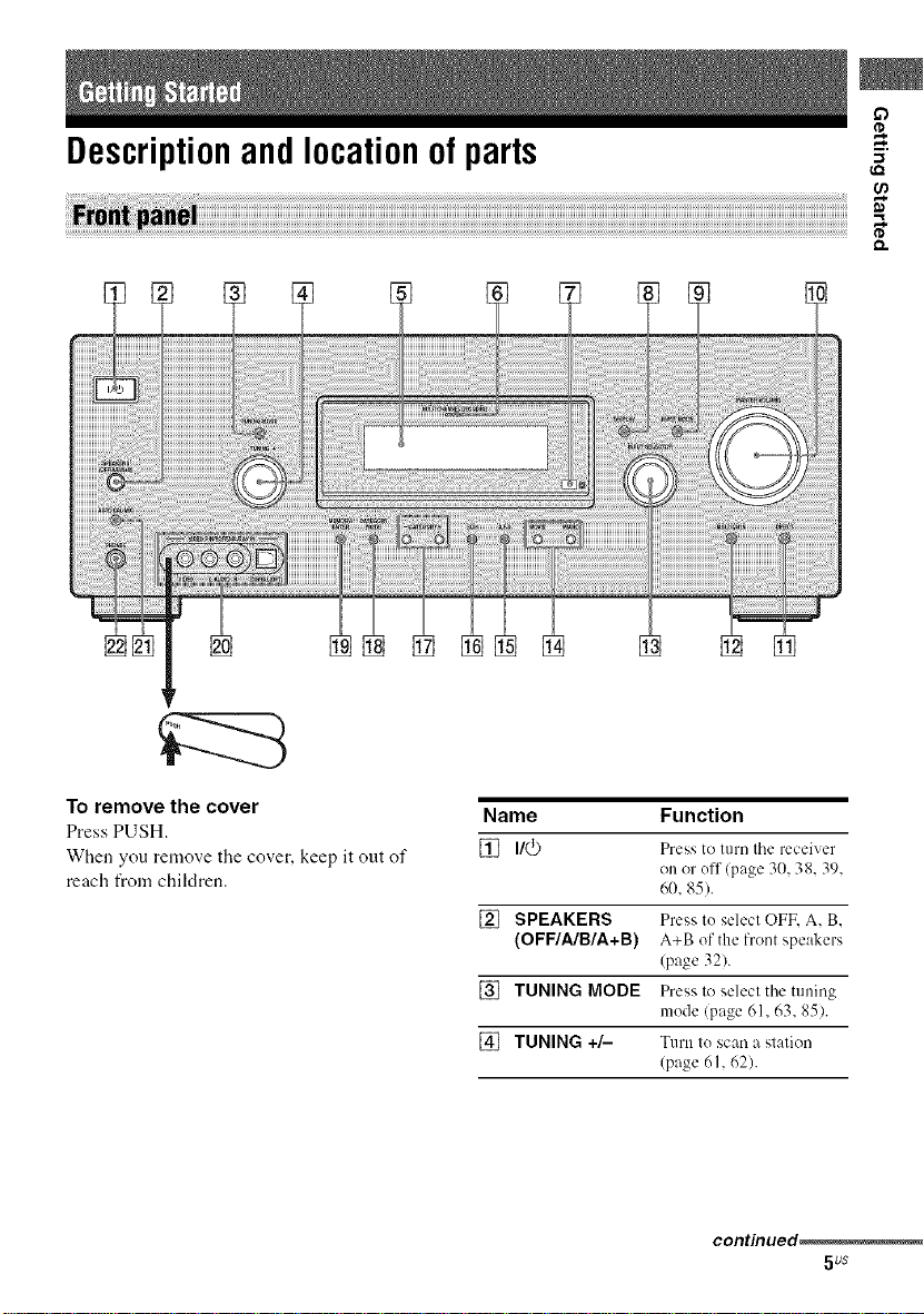
To remove the cover
Press PUSH.
When you remove the cover, keep it out of
reach from chiMren.
Name Function
[] I/(_) Press to turn tile receiver
on or off/page 30, 38, 39,
60, 85).
[] SPEAKERS Press to select OFF, A, B,
(OFF/A/B/A+B) A+B of the lront speakers
(page 321.
[] TUNING MODE Press to select tile tuning
mode (page 61, 63, 85).
[] TUNING +/- Turn to scan a station
(page 61, 62).
contmued_
5us
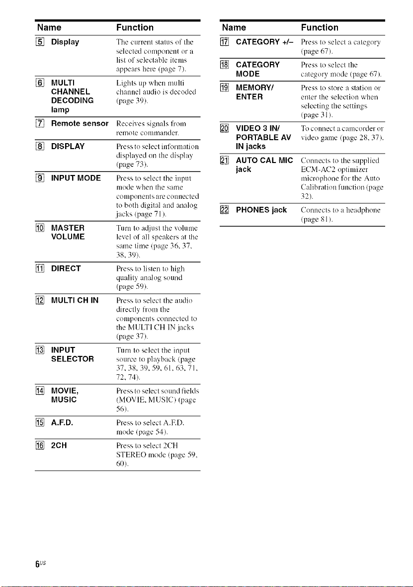
Name Function
[] Display The current status of the
selected cumponent or a
list uf selectable items
appears here (page 7).
[] MULTI Lights up when multi
CHANNEL channel audio is decuded
DECODING (page 39).
lamp
[] Remote sensor Receives signals from
[] DISPLAY Press tu select inlk_rmatiou
[] INPUT MODE Press to select the input
[] MASTER Turn to at[iust the volume
VOLUME level of all speakers at the
[] DIRECT Press to listen to high
[] MULTI CH IN Press to select the audiu
[] INPUT Turn to select the input
SELECTOR source to ph_yback (page
[] MOVIE, Press to select sound fields
MUSIC (MOVIE. MUSIC) (page
[] A.F.D. Press tu select A.ED.
[] 2CH Press to select 2CH
remute conm/ander.
displayed on the display
(page 73).
mode when the same
compuneuts are connected
to both digital and analog
.jacks (page 71 ).
same time (page 36. 37.
38.39).
quality analog sound
(page 59).
directly from the
compuneuts connected to
the MULTI CH IN jacks
(page 37).
37.38.39. 59.61.63.71.
72.74).
56).
mude (page 54).
STEREO mode (page 59.
60).
Name Fu nction
[] CATEGORY +/- Press to select a category
(page 67).
[] CATEGORY Press to select the
MODE category mode (page 67).
[] MEMORY/ Press to store a station ur
ENTER enter the selection when
selecting the settings
(page 31 ).
[] VIDEO 3 IN/ Tocuunectacamcorderur
PORTABLE AV video game (page 28, 37).
IN jacks
[] AUTO CAL MIC Connects to the supplied
jack ECM-AC2 optimizer
microphone for the Auto
C:dibratiun function (page
32).
[] PHONES jack Connects to a headphone
(page 81).
6us
if)
-1
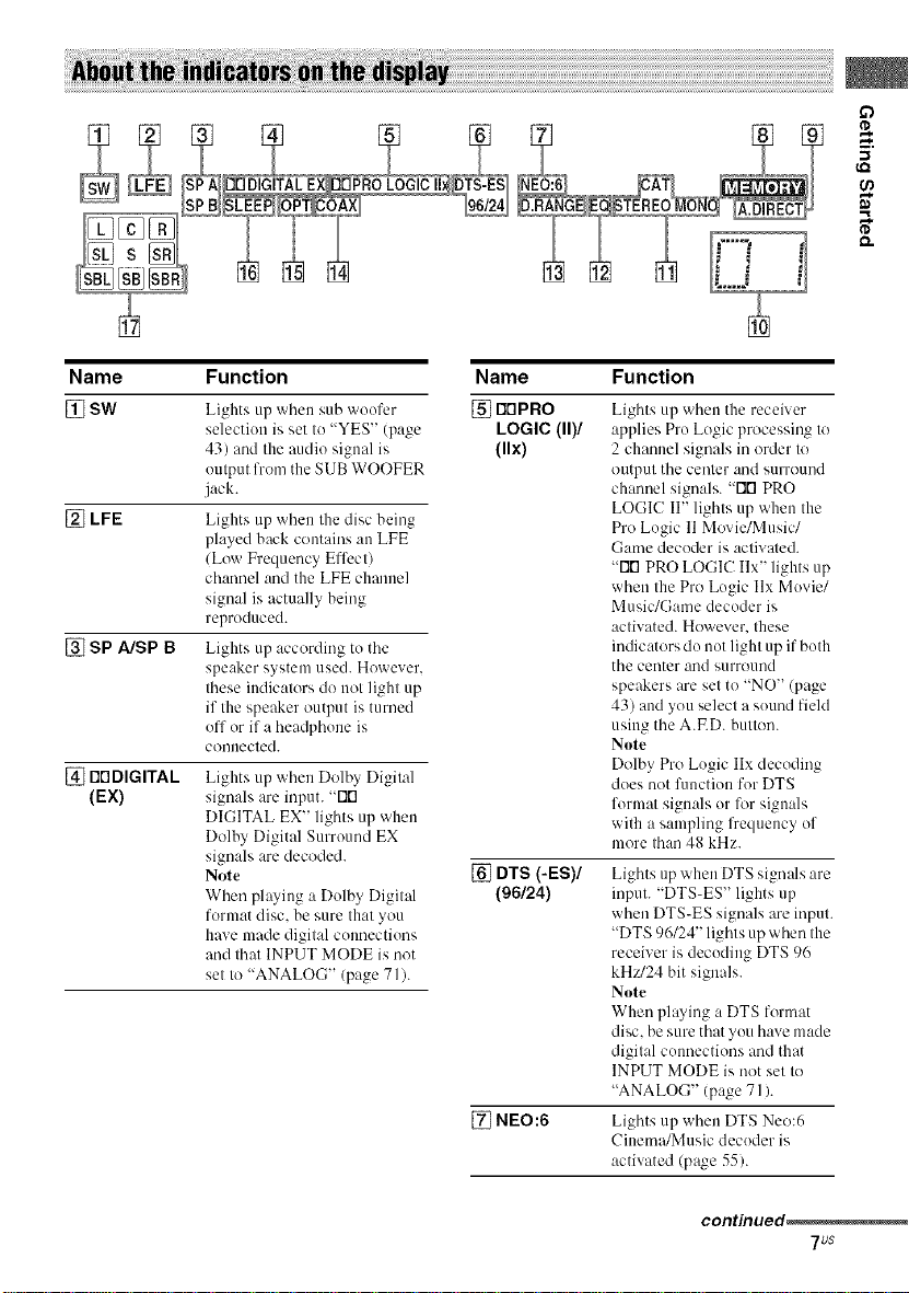
Name Function
[] SW
[] LFE
[] SP A/SP B
[] NDDIGITAL
(EX)
Lights up when sub woofer [] rlrlPRO
selection is set to "YES" (page LOGIC (11)1
43) and the audio signal is (llx)
output from the SUB WOOFER
jack.
Lights up wlmu the disc being
played back contains an LFE
/Low Frequency Effect)
channel and the LFE channel
signal is actually being
reproduced.
Lights up according to the
speaker system used. However,
these indicators do not light up
if the speaker output is turned
off or if a headphone is
connected.
Lights up when Dolby Digital
signals are input. "Flt'l
DIGITAL EX" lights up when
Dolby Digital Surround EX
signals are decoded.
Note
When playing a Dolby Digital
format disc, be sure that you
have made digital commctions
and that INPUT MODE is not
set to "ANALOG" (page 71).
Name Function
Lights tip when the receiver
applies Pro Logic processing to
2 channel signals in order to
output the center and surround
channel signals. -rlrl PRO
LOGIC II" lights up when the
Pro Logic 11Movie/Music/
Game decoder is actiwned.
"Flt'l PRO LOGIC Ilx" lights up
when the Pro Logic Ilx Movie/
Music/Game decoder is
activated. However, these
indicators do not light up if both
the center and surround
speakers are set to "NO" (page
43) attd you select a sound field
using the A.ED. button.
Note
Dolby Pro Logic IIx decoding
does not fimctiou for DTS
format signals or lkwsignals
with a sampling frequency of
more than 48 kHz.
[] DTS (-ES)/
(96124)
[] NEO:6 Lights up when DTS Neo:6
Lights tip when DTS signals are
input. "DTS-ES" lights up
when DTS-ES signals are input.
"DTS 96/24" lights up when the
receiver is decoding DTS 96
kH_'/24 bit signals.
Note
When playing :, DTS format
disc, be sure that you have made
digital connections and that
INPUT MODE is not set to
"ANALOG" (page 71 ).
Cinema/Music decoder is
activated (page 55).
continued_
7_s
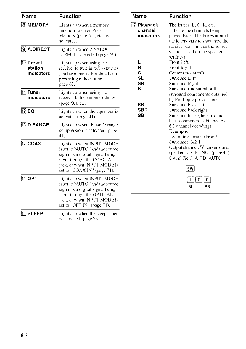
Name Function
[] MEMORY Lights up when :. memory
function, such as Preset
Memory (page 62), etc.. is
activated.
[] A.DIRECT Lights up when ANALOG
DIRECT is selected (page 59).
[] Preset Lights up when using the
station receiver tu tune in radio statiuus
indicators yuu have preset. Fur details on
presetting radio stations, see
page 62.
[] Tuner Lights up when using the
indicators receiver to tune in radio stations
(page 60), etc.
[] EQ Lights up when the equalizer is
activated (page 41 ).
[] D.RANGE Lights up when dynamic range
compression is activated (page
4_).
[] COAX Lights up when INPUT MODE
is set to "AUTO" and the source
signal is a digital signal being
input through the COAXIAL
jack. or when INPUT MODE is
set tu "COAX IN" (page 71 ).
[] OPT Lights up when INPUT MODE
is set to "AUTO" and the source
signal is a digital signal being
input through the OPTICAL
.jack. or when INPUT MODE is
set tu "OPT IN" (page 71 ).
[] SLEEP Lights up when the sleep timer
is activated (page 73).
Name
[] Playback
channel
indicators
L
R
C
SL
SR
S
SBL
SBR
SB
Function
The letters (L, C, R, etc./
indicate the channels being
played back. The boxes around
the letters vary to shuw how the
receiver dowuulixes the source
sound (based on the speaker
settings).
Fruut Left
Fruut Right
Center (monaural)
Surround Left
Surruuud Right
Surround (monaural or the
s/lrround conlponeuts obtaiued
by Pro Logic processing)
Surround back left
Surround back right
Surruuud back (the surround
back components ubtained by
6.1 channel decudiug)
Example:
Recording li_rmat (Front/
Surruuudh 3/2.1
Output channel: When surround
speaker is set tu "NO" (page 43)
Sound Field: A.ED. AUTO
SL SR
8 uS
if)
{,Q
8"
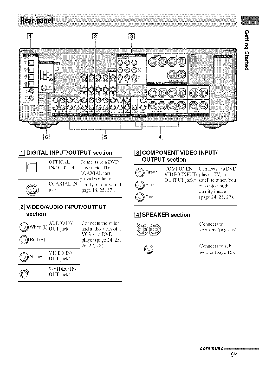
[] DIGITAL INPUT/OUTPUT section
OPTICAL Counects to a DVD
[] IN/OUT.jack player, etc. The
jack (page 18, 25, 27).
COAXIAL IN quality of loud sound
COAXIAL jack
provides a better
[] VIDEO/AUDIO INPUT/OUTPUT
section
Q White AUDIO IN/
Q Red (R)
Q Yellow VIDEO IN/
(L)
OUT jack
OUT jack
S-VIDEO IN/
OUT jack
Connects the video
and audio jacks of a
VCR or a DVD
player (page 24. 25.
26.27.28).
[] COMPONENT VIDEO INPUT/
OUTPUT section
Q COMPONENT Conuecls Io a DVD
Green VIDEO INPUT/player, TV, or a
Q Blue can ei!joy high
Q Red (page 24, 26, 27).
[] SPEAKER section
Q Connects Io sub
OUTPUT jack _ satellile tuner. You
quality image
Connects Io
speakers (page 16).
vvoofer (page 16).
contmued_
gus
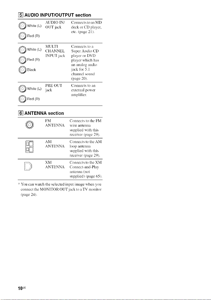
[] AUDIO INPUT/OUTPUT section
Q AUDIO IN/ Conneclsto an MD
White (L) OUT jack deck or CD player,
Q Red (R) etc. (page 21 ).
Q MULTI Connects tea
White(L) CHANNEL Super Audio CD
Q Red INPUT jack player er DVD
Q Black jnck for 5.1
Q PRE OUT Conllecls [e ,till
Q Red (R) amplifier.
(R)
White(L) jack exlernal pewer
player which has
an :re:dog audio
chnnnel seend
(page 20).
[] ANTENNA section
FM Connects to the FM
ANTENNA wire antenna
supplied with this
receiver (page 29).
AM Connects to tile AM
ANTENNA loop antenna
supplied with this
receiver (p_Jge 29).
D XM Colmects te tile XM
: Yeu can watch the selected input image when yeu
connect lhe MONITOR OUT jack te a TV meniter
(page 24).
ANTENNA Connect-and-Play
a/ltenea ([lot
supplied) (page 65).
lOUS
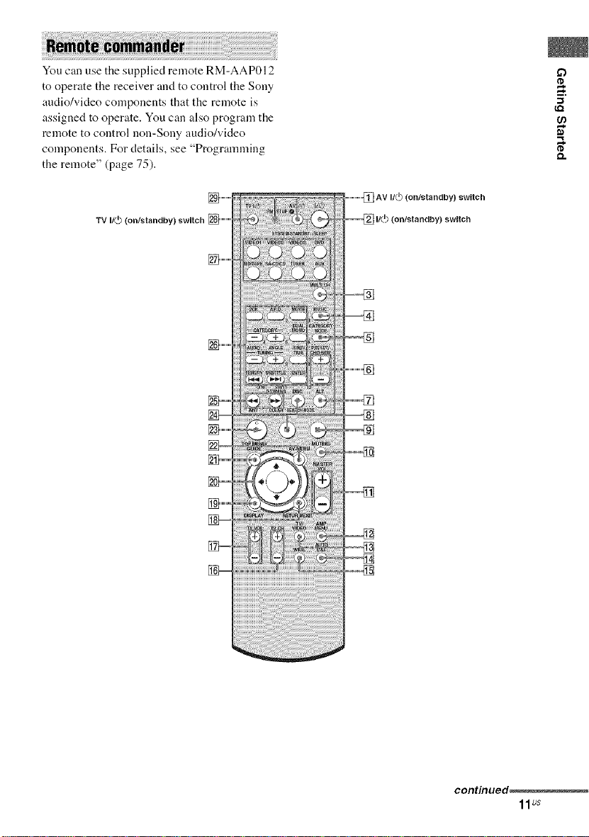
You can use the supplied remote RM-AAP012
to operate the receiver and to control the Sony
audio/video components that the remote is
assigned to operate. You can also program the
remote to control non-Sony audio/video
components. For details, see "Programming
the remote" (page 75).
O.
] ............
TV It(.I) (on/standby) switch [] ............
] ............
] ............
_w
] ............
AV If(._ (ontstandby) switch
If(._ (onfstandby) swRch
continued_
11us
Name
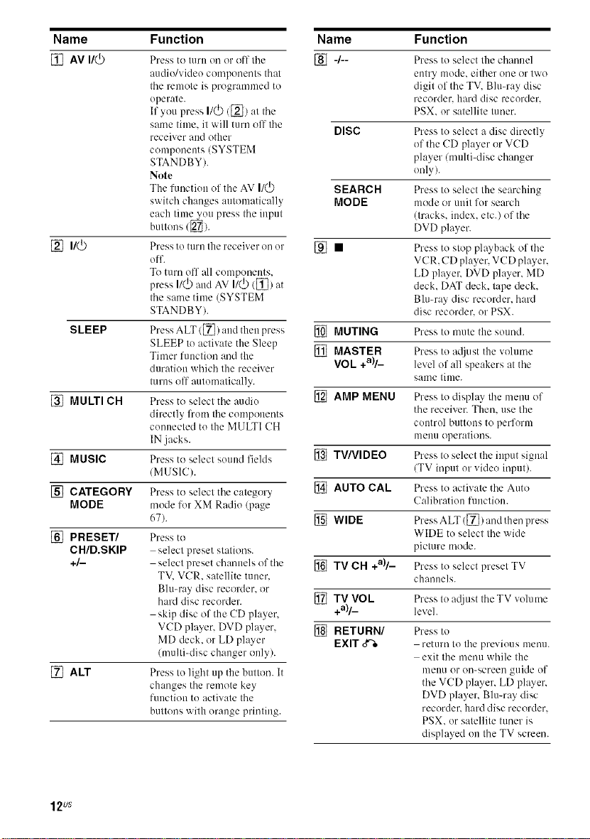
[] AV I/(_
SLEEP
[] MULTI CH
[] MUSIC
[] CATEGORY
MODE
[] PRESET/
CH/D.SKIP
+/-
[] ALT
Function
Press to turn on or off tile
audio/video components that
tile remote is programmed to
operate.
If you press I/(_)/[_) at tile
same time. it will turn off tile
receiver m_dother
components (SYSTEM
STANDBY).
Note
The function of tile AV I1_
switch changes automatically
each time you press the input
buttons ([_).
Press to t/lrn the receiver on or
off.
To turn off all components,
press I/_ and AV I/_ ([])at
tile same time (SYSTEM
STANDBY).
Press ALT/[]) :rod then press
SLEEP to activate the Sleep
Timer function :rod the
duration which the receiver
turns off automatically.
Press to select tile audio
directly from tile components
connected to the MULTI CH
IN jacks.
Press to select sound fields
/MUSIC).
Press to select the category
mode for XM Radio (page
67).
Press to
select preset stations.
select preset channels of the
TV. VCR. satellite tuner.
Blu-ray disc recorder, or
hard disc recorder.
skip disc of the CD player.
VCD player. DVD player,
MD deck. or LD player
(multi-disc changer only).
Press to light up the button. It
changes the remote key
function to activate the
buttons with orange printing.
Name Function
[] 4- Press to select tile chamml
entry mode. either one or two
digit of the TV. Blu-ray disc
recorder, hard disc recorder.
PSX. or satellite tuner.
DISC Press to select a disc directly
SEARCH Press to select the searching
MODE mode or unit for search
[] • Press to stop ph_yback of the
[] MUTING Press to mute the sound.
[] MASTER Press to mliust the volume
VOL +a)/_ level of all speakers at tile
[] AMP MENU Press to display tile menu of
[] TV/VIDEO Press to select the input signal
[] AUTO CAL Press to activate tile Auto
[] WIDE Press ALT ([]) and then press
[] TV CH +all_ Press to select presel TV
[] TV VOk Press to mljust tile TV volume
+all_ level.
[] RETURN/ Press to
EXIT 3% return to the previous metal
of tile CD player or VCD
player/multi-disc changer
only).
(tracks. index, etc.) of the
DVD player.
VCR. CD player. VCD player,
LD playelv DVD player. MD
deck. DAT deck. tape deck.
Blu-ray disc recorder, hard
disc recorder, or PSX.
same time.
the receiver. Then. use the
control buttons to perform
menu operations.
(TV input or video input).
Ca]ibration function.
WIDE to select the wide
picture mode.
channels.
exit tile menu while the
melm or on-screen guide of
the VCD player, LD player.
DVD player, Blu-ray disc
recorder, hard disc recorder.
PSX. or satellite tuner is
displayed on the TV screen.
12us
Name Function
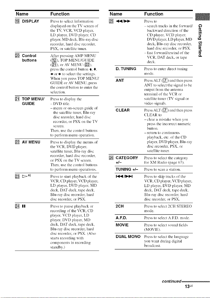
DISPLAY
Control
buttons
[_ TOP MENU/
GUIDE
AV MENU
t:>a)
[] II Press to pause playback or
Press to select inlk_rmatiou
displayed on the TV screen of
the TV. VCR. VCD player,
LD player. DVD player. CD
player. MD deck. Blu-ray disc
recorder, hard disc recorder.
PSX, or satellite tuner.
After pressing AMP MENU
([_), TOP MENU/GUIDE
(_]), or AV MENU ([]),
press the control button t. _.
._.or .*'to select the settings.
When you press TOP MENU/
GUIDE or AV MENU, press
the control button to enter the
selection.
Press to display the
DVD title.
menu or on-screen guide of
the satellite tuner. Blu-ray
disc recorder, hard disc
recorder, or PSX on the TV
screen.
Then. use the control buttons
to perform menu operation.
Press to display the mmms of
the VCR. DVD player,
satellite tuner. Blu-ray disc
recorder, hard disc recorder.
or PSX on the TV screen.
Then. use the control buttons
to perlk_rm mmm operations.
Press to start playback ol' the
VCR. CD player, VCD player,
LD player. DVD player. MD
deck. DAT deck. tape deck.
Bit>ray disc recorder, hard
disc recorder, or PSX.
recording of the VCR. CD
player. VCD player. LD
player. DVD player. MD
deck. DAT deck. tape deck.
Bit>ray disc recorder, hm'd
disc recorder, or PSX. (Also
starts recording with
components in recording
standby.)
Name Function
[] <<I/IH_
D. TUNING
ANT
CLEAR
[] CATEGORY Press to select the category
+/- for XM Radio (page 67).
TUNING +/- Press to scan a station.
/I_Ip't Press to skip tracks of the
2CH Press to select 2CH STEREO
A.F.D. Press to select A.F.D. mode.
MOVIE Press to select souud fields
DUAL MONO Press to select the language
Press to
search tracks in the forward/
backward direction of the
CD player. VCD player, -_
DVD player, LD player. MD
deck, Blu-ray disc recorder, €_
hard disc recorder, or PSX.
fast forward/rewind of the _"
VCR. DAT deck. or tape
deck.
Press to enter direct tnning
mode.
Press ALT/[_) and then press
ANT to select the signal to be
output l_'om the antenna
terminal of the VCR or
satellite tuner (TV signal or
video signal/.
Press ALT ([_) and then press
CLEAR to
clear a mistake when you
press the incorrect numeric
button.
retllrn to contiuuous
playback, elc. of the CD
player, DVD player, Blu-ray
disc recorder. PSX. or
satellite tuner.
VCR. CD player, VCD player,
LD player, DVD player. MD
deck. DAT deck, tape deck.
Blu-ray disc recordel, hard
disc recorder` or PSX.
mode.
(MOVIE).
you want during digital
broadcast.
continued .....
13us
Name
AUDIO
ANGLE
JUMP/TIME
MEMORY
SUBTITLE
ENTER
Numeric
buttons
>10/11
Function
Press to change tile sound to
Multiplex, Bilingual or Multi
channel TV sound of tile TV.
VCR. DVD player, satellite
tuner. Blu-ray disc recorder.
hard disc recorder, or PSX.
Press to select the viewing
angle or change tile attgles of
tile DVD player or Blu-ray
disc recorder.
Press to
toggle between the previous
and the current channels of
the satellite tunel_ TV. or
Blu-ray disc recorder.
show the time or display the
playing time of a disc. etc. of
the CD player. MD deck.
VCD player, or DVD player.
Press MEMORY to store a
station.
Press ALT/[_) :rod then press
SUBTITLE tit change the
subtitles of the DVD player.
Press ALT 1[_) and then press
ENTER to enter the value
after selecting a channel, disc
or track using the numeric
buttons.
Press ALT ([_) and then press
the numeric buttons to
preset/tune to preset
stations.
select track numbers of the
CD player. VCD player. LD
player, DVD player, MD
deck. DAT deck. or tape
deck. Press 0/lit tit select
tr:lL'k t_lumber IO.
select channel numbers of
the TV. VCR. satellite tuner.
Bit>ray disc recorder, hard
disc recorder, or PSX.
Press ALT/[_) and then press
>10/11 to select track
numbers over 10 of the CD
player, VCD player. LD
player, MD deck. tape deck.
TV. VCR. Blu-ray disc
recorder, hard disc recorder.
PSX. or satellite tuner.
Name Function
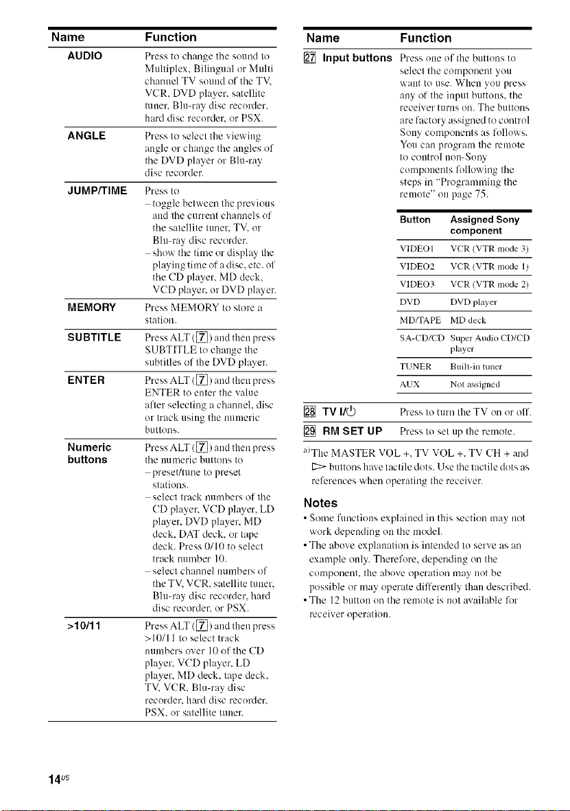
[] Inputbuttons
Press one of the buttons to
select the component you
want tit use. When you press
any of the input buttons, the
receiver turns oil. The buttons
are factory assigned to control
Sony components as follows.
You can program the remote
to control non-Sony
components following the
steps in "Progr:unnfing the
remote" on page 75.
Button Assigned Sony
VIDEO I VCR (VTR nlode 3)
VIDEO2 VCR (VTR mode 1)
VIDEO3 VCR (VTR nlode 2)
DVD DVD player
MD/TAPE MD deck
SA-CD/CD Super Audio CD/CD
TUNER Buill-in tuner
AUX Not assigned
component
player
[] TV I/(_ Press to turn theTV onor off.
[] RM SET UP Press Io sel tip the remote.
a)The MASTER VOL +. TV VOL +. TV CH + and
E:::> buttons hax e tactile dots. Use the tactile dots as
references when operating the receiver.
Notes
• Some functions explained in this section may not
work depending on the model.
• The above explanation is intended to serve as an
example only. Therefore. depending on the
component, the above operation may not be
possible or may operate differently than described.
• The 12 button on the remote is not available 17_r
receiver operation.
14us
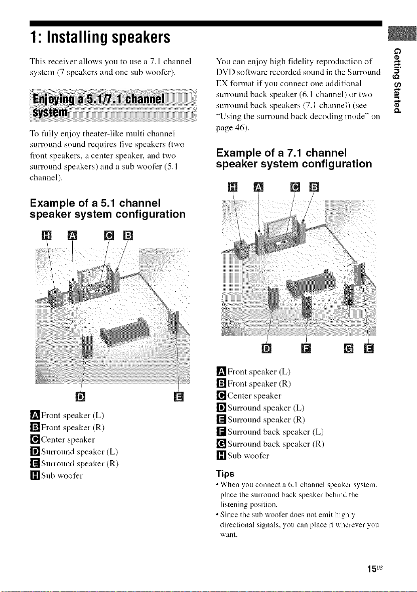
1: Installingspeakers
This receiver allows you to use a 7.1 channel
system (7 speakers and one sub woofer).
To tully enjoy theater-like nmlti channel
surround sound requires five speakers (two
t_ont speakers, a center speaker, and two
surround speakers) and a sub woofer (5.1
channel).
Example of a 5.1 channel
speaker system configuration
You can enjoy high fidelity reproduction of
DVD software recorded sound in the Surround "_
EX format if you connect one additional
surround back speaker (6.1 channel) or two
surround back speakers (7.1 channel) (see
"Using the surround back decoding mode" on
page 46).
Example of a 7.1 channel
speaker system configuration
[] r=
m,
[]Front speaker (L)
rfflFront speaker (R)
_l]Center speaker
r_Snrround speaker (L)
rllSnrround speaker (R)
r_'l Sub woofer
I_Front speaker (L)
[]Front speaker (R)
[]Center speaker
[]Surround speaker (L)
rllSnrronnd speaker (R)
rdSnrronnd back speaker (L)
_Snrronnd back speaker (R)
r_lsnb woofer
Tips
•When _ou connect a 6.1 channel speaker s_stem,
place the surround back speaker behindthe
listening position.
•Since the sub wooferdoes not emit highly
directional signals,you can place it wherever you
want.
15us
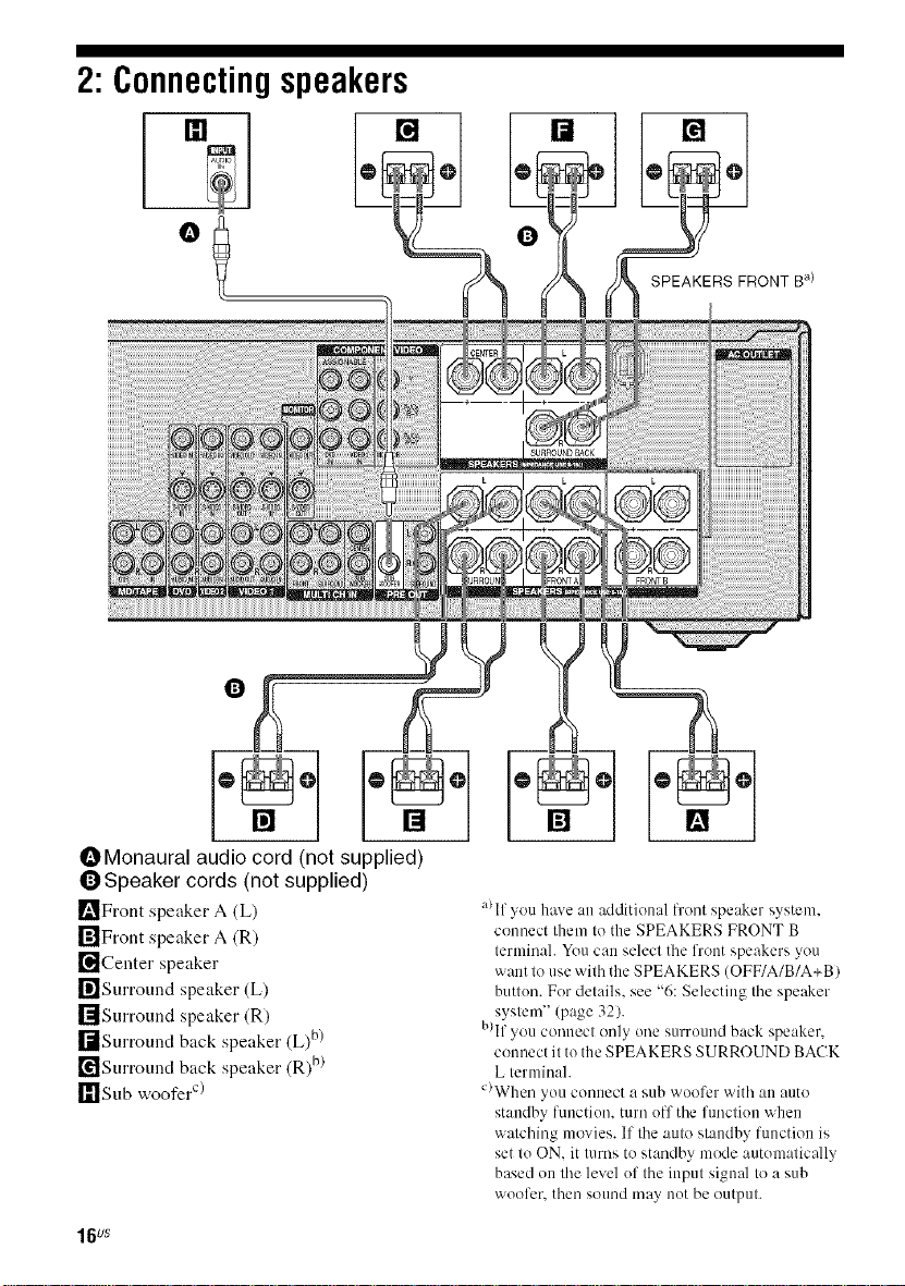
2: Connectingspeakers
[]
iiiiiiiiiiiiiiii
[]
OMonaural audio cord (not supplied)
(])Speaker cords (not supplied)
[_Front speaker A (L)
rfflFront speaker A (R)
["_Center speaker
_]Surround speaker (L)
rllSurround speaker (R)
I-dSurmund back speaker (L)b)
['_Surround back speaker (R)b)
_11Sub woofer c/
16us
a)If you have an additional lront speaker system.
counect them to the SPEAKERS FRONT B
terminal. You can select the front speakers you
want to use with the SPEAKERS (OFF/A/B/A+BI
button. For details, see "6: Selecting tile speaker
system" (page 32).
B)If you connect only one surround back speaker.
c(mnect it to the SPEAKERS SURROUND BACK
L terminal.
C)When you connect a sub wuofcr with an auto
standby function, turn off the function when
watching movies. If the auto standby function is
set to ON. it turns to standby mode automatically
based on the level of the input signal to a sub
woofer, then sound may not be output.
3a: Connectingtheaudiocomponents
This section describes how to hook up your
components to this receiver. Before you begin,
refer to "Component to be connected" below
for the pages which describe how to connect
each component.
Alter hooking up all your components,
proceed to "4: Connecting the antennas" (page
29).
Component to be connected
Component With Page
Super Audio Digital audio output _) 18
CD player/CD Multi-channel audio 20
player _ _ b)
MD deck/Tape Digital audio output a/ 18
deck
a)Model with DIGITAL OPTICAL OUTPUT or
DIGITAL COAXIAL OUTPUT jack, etc.
b)Model with MULTI CH OUTPUT jacks, etc. This
connection is used to output audio decoded by the
componeut's internal multi-channel decoder
through this receiver.
C)Model equipped only with AUDIO OUT L/R
.jacks. etc.
( u(1 ut
Analog audio output 21
only c)
Analog audio output 21
only c)
-1
17us
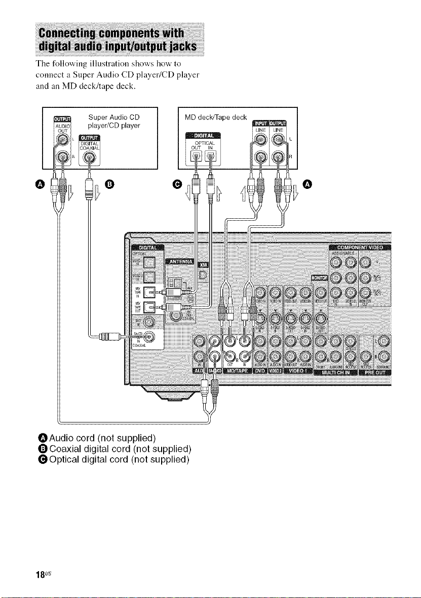
The following illustration shows how to
connect a Super Audio CD player/CD player
and an MD deck/tape deck.
player/CD player
__R Su_er Audio CD
°l °
OAudio cord (not supplied)
OCoaxial digital cord (not supplied)
_Optical digital cord (not supplied)
18us
Notes on playing a Super Audio
CD disc on a Super Audio CD
player
• No sound is output when you play a Super
Audio CD disc on a Super Audio CD player
connected to only the SA-CD/CD
COAXIAL IN jack on this receiver. When
you play a Super Audio CD disc, connect the
player to the MULTI CH IN or SA-CD/CD
IN jack. Refer to the operating instructions
supplied with the Super Audio CD player.
• You cannot make digital recordings if you
make only analog connections. Likewise,
you cannot make analog recordings if you
make only digital connections. To make
digital recordings, make digital connections
and to make analog recordings, make analog
connections.
• You cannot make digital recordings of a
Super Audio CD disc. Use the analog jack
for recording in this case.
• When connecting optical digital cords, insert
the plugs straight in until they click into
place.
• Do not bend or tie optical digital cords.
rip
All the digital audio jacks are compatible with
32 kHz, 44.1 kHz, 48 kHz, and 96 kHz sampling
frequencies.
if)
19us
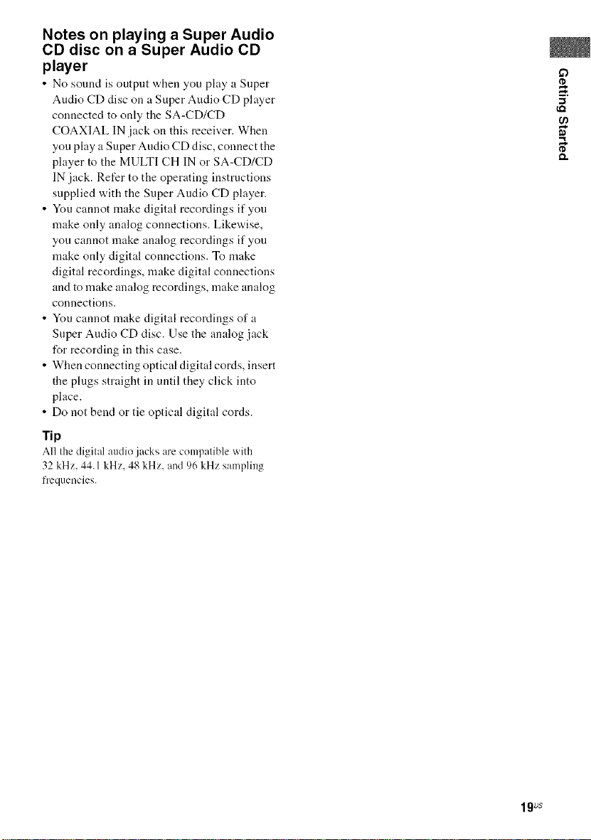
If your DVD or Super Audio CD player is
equipped with multi channel output jacks, you
can connect it to the MULTI CH IN jacks of
this receiver to enjoy multi channel sound.
Alternatively, the multi channel input jacks
can be used to connect an external multi
channel decoder.
Note
When you make connections to tile MULTI CH IN
jacks, you will need to atliust tile level of the
speakers and sub woofer using the controls on the
connected component.
DVD player, Super
Audio CD player, etc.
OAudio cord (not supplied)
OMonaural audio cord (not supplied)
20us
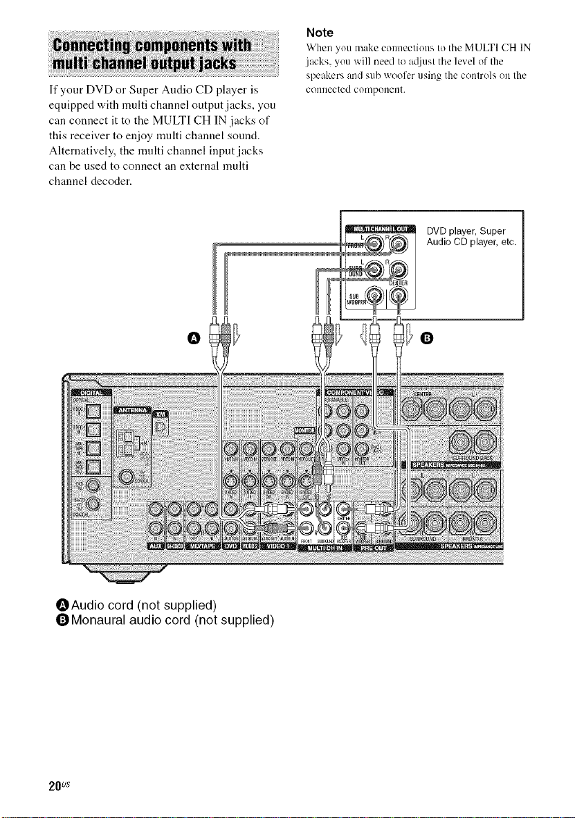
The following illustration shows how to
connect a component which has analog .jacks
such as tape deck, etc.
CD player/
CD player
ruo
L Tape deck
MD deck/
CD player,
MD deck,
tape deck. etc. '_
OAudio cord (not supplied)
: YOU can connecl all audio cenlpelleel (except
turnlable) te tile AUX IN jack so thai you Call
listen te steree sources in surreund sound.
21us
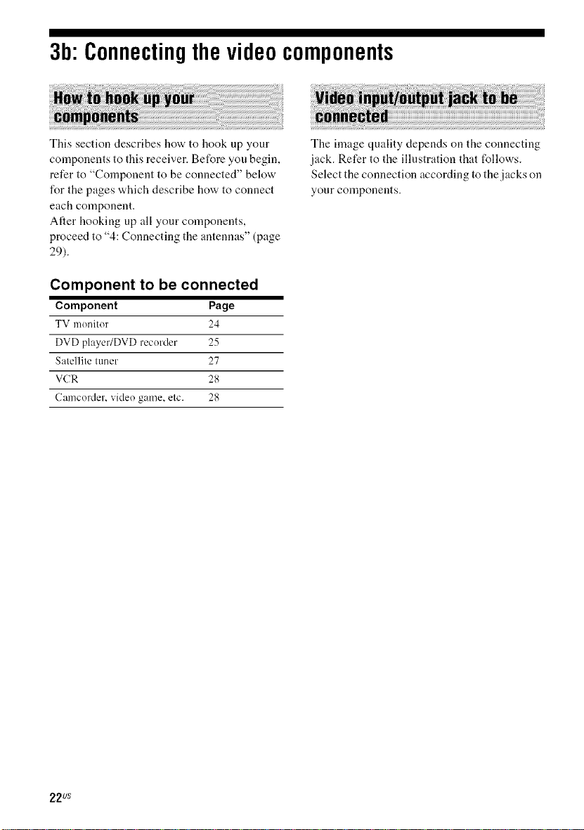
3b:Connectingthevideocomponents
This section describes how to hook up your
components to this receiver. Before you begin,
refer to "Component to be connected" below
l\w the pages which describe how to connect
each component.
After hooking up all your components,
proceed to "4: Connecting the antennas" (page
29).
Component to be connected
Component Page
TV monitor 24
DVD player/DVD recorder 25
Satellite tuner 27
VCR 28
Camcorder, video game, etc. 28
The finage quality depends on the connecting
jack. Refer to the illustration that follows.
Select the connection according to the jacks on
your components.
22us
£3
(,Q
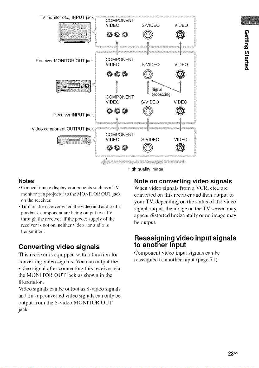
Receiver MONITOR OUT jack
COMPONENT
VIDEO S-VIDEO VIDEO
@@@ (@
COMPONENT processing
VIDEO S-VIDEO VIDEO
Receiver INPUT jack
Video component OUTPUT jack
Notes
• Connect image displ:_y components such :is :JTV
monitor or a projector to tile MONITOR O{JT.jack
on the receiver.
• Turn on the receiver when the video and audie efa
playback cornpenent are being output tea TV
through the receiver. If the power supply of the
receiver is net on. neither video nor audio is
transmitted.
Converting video signals
This receix.er is equipped with a function for
converting video signals. You can output the
video signal alter connecting this receiver via
the MONITOR OUT jack as shown in the
illustration.
Video signals can be output as S-video signals
and this upconverted video signals can only be
output from the S-video MONITOR OUT
jack.
@@@ (@
High quality image
Note on converting video signals
When video signals from a VCR, etc., are
converted on this receiver and then output to
your TV, depending on the status of the video
signal output, the image on the TV screen may
appear distorted horizontally or no image may
be output.
Reassigning video input signals
to another input
Component ",,Meo input signals can be
reassigned to another input (page 71 ).
23us
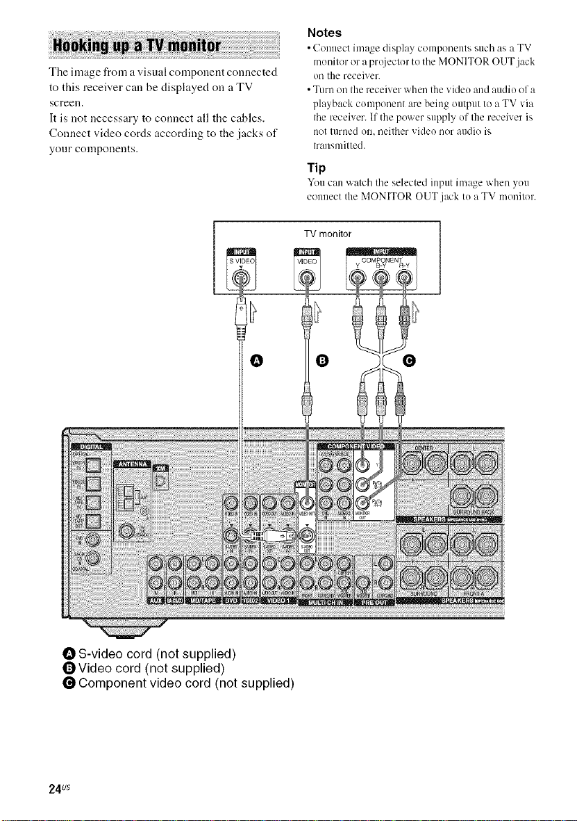
The image from avisual component connected
to this receiver call be displayed on a TV
screen.
It is not necessary to connect all the cables.
Connect video cords according to the jacks of
your components.
O O
Notes
• Connect image displa_ components such as a TV
monitor or a prt_iector to the MONITOR OUT jack
on the receiver.
• Turn on the receiver when the vide() and audio of a
playback component are being output to a TV via
the receiver. If the power supply of the receiver is
not turned on, neither video nor audio is
transmitted.
Tip
Youcan watch tileselected input image when you
connect the MONITOR OUT jack to a TV monitor.
S-video cord (not supplied)
_Video cord (not supplied)
0 Component video cord (not supplied)
24us
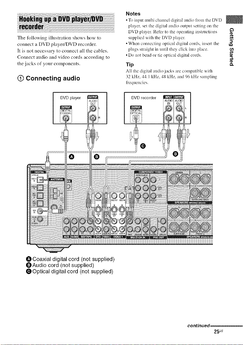
The following illustration shows how to
connect a DVD playedDVD recorder.
It is not necessary to connect all the cables.
Connect audio and video cords according to
the jacks of your components.
(_) Connecting audio
Notes
• Te iupm multi chaunel digital audio IYom tile DVD
player, set the digilal audio outpul setting on the
DVD player. Refer te Ihe eperaling inslructiees _2_
supplied with the DVD player. _.
• When cenueclieg eplical digilal cerds, insert the
plugs slraighl in until they click inte place.
• De net bend er tie eplical digilal cords.
Tip _-
All Ihe digilal audio jacks are compatible with
32 kHz, 44. I kHz, 4g kHz, and 96 kHz sampling
frequencies.
DVDrecorder
I DVDvlayer
OCoaxial digital cord (not supplied)
OAudio cord (not supplied)
l_Optical digital cord (not supplied)
DIC AL
continued,
25us
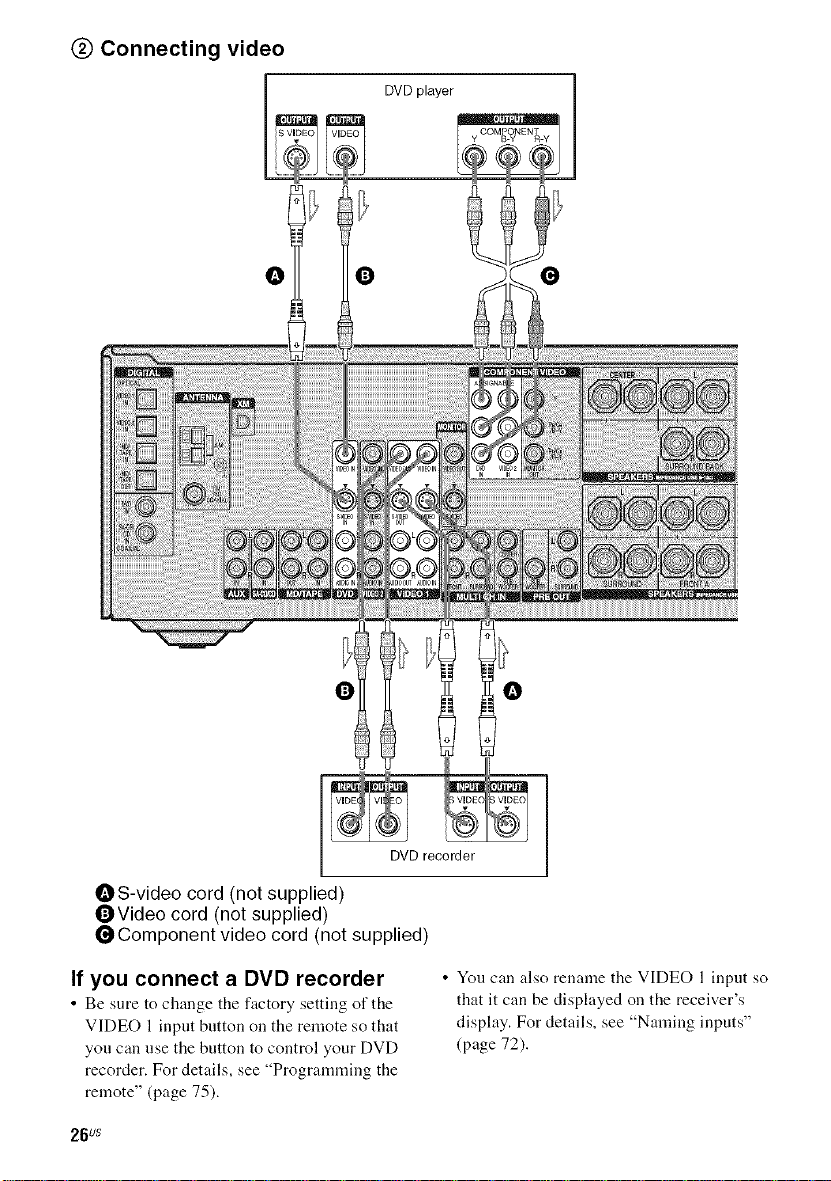
@ Connecting video
COMP?NENT_
DVDplayer_,.
O O O
O O
OS-video cord (not supplied)
OVideo cord (not supplied)
_Component video cord (not supplied)
If you connect a DVD recorder
• Be sure to change tile factory setting of tile
VIDEO 1 input button on the remote so that
you can use the button to control your DVD
recorder. For details, see "Programming the
remote" (page 75).
26us
DVD recorder
• Yotl can also rename the VIDEO l input so
that it can be displayed on the receiver's
display. For details, see "Naming inputs"
(page 72).
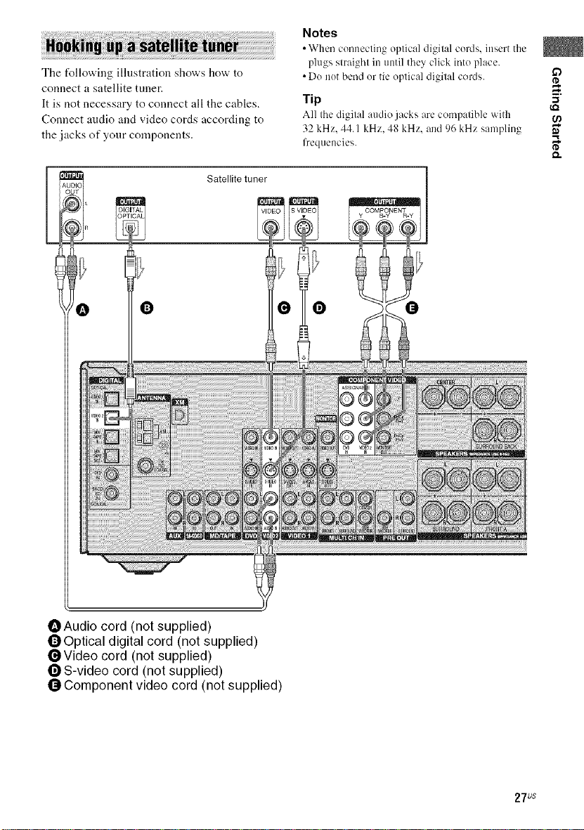
The following illustration shows how to
connect a satellite tuner.
It is not necessary to connect all the cables.
Connect audio and video cords according to
the jacks of your components.
Satellite tuner
Notes
• When cennecling eplical digilal ceMs. insert the
plugs slraigl'll in until they click irlte place.
• De net bend er tie eplical digilal coMs.
Tip "_
All Ihe digilal audio jacks are compatible with
32 kHz. 44.1 kHz. 48 kHz. and 96 kHz sampling
frequencies. _"
0
OAudio cord (not supplied)
OOptical digital cord (not supplied)
_Video cord (not supplied)
0 S-video cord (not supplied)
0 Component video cord (not supplied)
0 0
27us
 Loading...