

Sony STRDG-520 Service manual
STR-DG520
SERVICE MANUAL
Ver. 1.0 2008.02
Photo: Black type
Manufactured under license from Dolby Laboratories.
Dolby, Pro Logic, and the double-D symbol are trademarks of Dolby
Laboratories.
Manufactured under license under U.S. Patent
#’s: 5,451,942; 5,956,674; 5,974,380; 5,978,762;6,487,535
& other U.S. and worldwide patents issued & pending.
DTS and DTS Digital Surround are registered trademarks and
the DTS logos and Symbol are trademarks of DTS, Inc.
© 1996-2007 DTS, Inc. All Rights Reserved.
This receiver incorporates High-Defi nition Multimedia Interface
TM
(HDMI
HDMI, the HDMI logo and High-Defi nition Multimedia Interface
are trademarks or registered trademarks of HDMI Licensing LLC.
) technology.
US Model
Canadian Model
AEP Model
UK Model
SPECIFICATIONS
AUDIO POWER SPECIFICATIONS
POWER OUTPUT AND TOTAL HARMONIC DISTORTION:
(Models of area code US only)
With 8 ohm loads, both channels driven, from 20 – 20,000 Hz; rated 90
watts per channel minimum RMS power, with no more than 0.09 % total
harmonic distortion from 250 milliwatts to rated output.
Amplifi er section
Models of area code US, CND
Minimum RMS Output Power (8 ohms, 20 Hz – 20 kHz, THD 0.09%)
90 W + 90 W
Stereo Mode Output Power (8 ohms, 1 kHz, THD 1%)
100 W + 100 W
Surround Mode Output Power 2) (8 ohms, 1 kHz, THD 10%)
130 W/ch
Models of area code AEP, UK
Minimum RMS Output Power (8 ohms, 20 Hz – 20 kHz, THD 0.09%)
85 W + 85 W
Stereo Mode Output Power (8 ohms, 1 kHz, THD 1%)
100 W + 100 W
Surround Mode Output Power
130 W/ch
1)
1)
2)
(8 ohms, 1 kHz, THD 10%)
9-887-995-01
2008B04-1
2008.02
©
– Continued on next page –
MULTI CHANNEL AV RECEIVER
Sony Corporation
Audio Business Group
Published by Sony Techno Create Corporation

STR-DG520
1) Measured under the following conditions:
Area code Power requirements
US, CND 120 V AC, 60 Hz
AEP, UK 230 V AC, 50 Hz
2) Reference power output for front, center and surround speakers.
Depending on the sound fi eld settings and the source, there may be
no sound output.
Frequency response
Analog 10 Hz – 70 kHz
+0.5/–2 dB (with sound
fi eld and tone bypassed)
Inputs
Analog Sensitivity: 500 mV/
50 kohms
S/N 3) : 96 dB
(A, 500 mV
4)
)
Digital (Coaxial) Impedance: 75 ohms
S/N: 100 dB
(A, 20 kHz LPF)
Digital (Optical) S/N: 100 dB
(A, 20 kHz LPF)
Output (Analog)
AUDIO OUT Voltage: 500 mV/10 kohms
SUB WOOFER Voltage: 2 V/1 kohm
Tone
Gain levels ±6 dB, 1 dB step
3) INPUT SHORT (with sound fi eld and tone bypassed).
4) Weighted network, input level.
FM tuner section
Tuning range 87.5 – 108.0 MHz
Antenna FM wire antenna
Antenna terminals 75 ohms, unbalanced
Intermediate frequency 10.7 MHz
General
Power requirements
Area code Power requirements
US, CND 120 V AC, 60 Hz
AEP, UK 230 V AC, 50/60 Hz
Power output (DIGTAL MEDIA PORT)
DC OUT : 5 V, 0.7 A MAX
Power consumption
Area code Power consumption
US, AEP , UK 220 W
CND 300 VA
Power consumption (during standby mode)
0.3 W
Dimensions (w/h/d) (Approx.)
430 × 157.5 × 318 mm
(16
7/8 × 6 2/8 × 12 5/8 inches) including
projecting parts and controls
Mass (Approx.) 7.7 kg (16 lb 16 oz)
Supplied accessories
Operating Instruction (1)
Quick Setup Guide (1)
FM wire antenna (aerial) (1)
AM loop antenna (aerial) (1)
Remote commander RM-AAU020 (1)
R6 (size-AA) batteries (2)
Optimizer microphone ECM-AC2 (1) (AEP, UK)
Design and specifi cations are subject to change without notice.
• Abbreviation
CND : Canadian model
AM tuner section
Tuning range
Models of area code US, CND
With 10-kHz tuning scale: 530 – 1,710 kHz
With 9-kHz tuning scale: 531 – 1,710 kHz
5)
5)
Models of area code AEP, UK
With 9-kHz tuning scale: 531 – 1,602 kHz
Antenna Loop antenna
Intermediate frequency 450 kHz
5) You can change the AM tuning scale to 9 kHz or 10 kHz.After tuning
in any AM station, turn off the receiver. While holding down TUNING
MODE, press ?/1. All preset stations will be erased when you change
the tuning scale.To reset the scale to 10 kHz (or 9 kHz), repeat the
procedure.
Video section
Inputs/Outputs
Video: 1 Vp-p/75 ohms
COMPONENT VIDEO: Y : 1 Vp-p/75 ohms
P
B/CB: 0.7 Vp-p/
75 ohms
P
R/CR: 0.7 Vp-p/
75 ohms
80 MHz HD Pass Through
2
STR-DG520
SAFETY CHECK-OUT (US MODEL)
After correcting the original service problem, perform the following safety check before releasing the set to the customer:
Check the antenna terminals, metal trim, “metallized” knobs,
screws, and all other exposed metal parts for AC leakage.
Check leakage as described below.
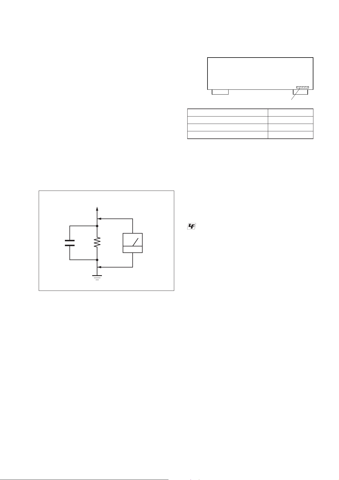
LEAKAGE TEST
The AC leakage from any exposed metal part to earth ground and
from all exposed metal parts to any exposed metal part having a
return to chassis, must not exceed 0.5 mA (500 microamperes.).
Leakage current can be measured by any one of three methods.
1. A commercial leakage tester, such as the Simpson 229 or RCA
WT-540A. Follow the manufacturers’ instructions to use these
instruments.
2. A battery-operated AC milliammeter. The Data Precision 245
digital multimeter is suitable for this job.
3. Measuring the voltage drop across a resistor by means of a
VOM or battery-operated AC voltmeter . The “limit” indication
is 0.75 V, so analog meters must have an accurate low-voltage
scale. The Simpson 250 and Sanwa SH-63Trd are examples
of a passive VOM that is suitable. Nearly all battery operated
digital multimeters that have a 2 V AC range are suitable. (See
Fig. A)
To Exposed Metal
Parts on Set
MODEL IDENTIFICATION
–BACK PANEL–
Part No.
Model Part No.
US
CND
AEP, UK
• Abbreviation
CND : Canadian model
3-279-308-0[]
3-279-308-1[]
3-279-308-2[]
Notes on chip component replacement
• Never reuse a disconnected chip component.
• Notice that the minus side of a tantalum capacitor may be damaged by heat.
UNLEADED SOLDER
Boards requiring use of unleaded solder are printed with the leadfree mark (LF) indicating the solder contains no lead.
(Caution: Some printed circuit boards may not come printed with
the lead free mark due to their particular size)
AC
1.5 kΩ0.15 μF
Earth Ground
voltmeter
(0.75 V)
Fig. A. Using an AC voltmeter to check AC leakage.
: LEAD FREE MARK
Unleaded solder has the following characteristics.
• Unleaded solder melts at a temperature about 40 °C higher
than ordinary solder.
Ordinary soldering irons can be used but the iron tip has to be
applied to the solder joint for a slightly longer time.
Soldering irons using a temperature regulator should be set to
about 350 °C.
Caution: The printed pattern (copper foil) may peel away if the
heated tip is applied for too long, so be careful!
• Strong viscosity
Unleaded solder is more viscous (sticky, less prone to fl ow)
than ordinary solder so use caution not to let solder bridges
occur such as on IC pins, etc.
• Usable with ordinary solder
It is best to use only unleaded solder but unleaded solder may
also be added to ordinary solder.
SAFETY-RELATED COMPONET WARNING!
COMPONENTS IDENTIFIED BY MARK 0 OR DOTTED LINE
WITH MARK 0 ON THE SCHEMATIC DIAGRAMS AND IN
THE PARTS LIST ARE CRITICAL TO SAFE OPERATION.
REPLACE THESE COMPONENTS WITH SONY PARTS
WHOSE PART NUMBERS APPEAR AS SHOWN IN THIS
MANUAL OR IN SUPPLEMENTS PUBLISHED BY SONY.
ATTENTION AU COMPOSANT AYANT RAPPORT
À LA SÉCURITÉ!
LES COMPOSANTS IDENTIFIÉS PAR UNE MARQUE 0 SUR
LES DIAGRAMMES SCHÉMATIQUES ET LA LISTE DES
PIÈCES SONT CRITIQUES POUR LA SÉCURITÉ DE FONCTIONNEMENT. NE REMPLACER CES COM- POSANTS QUE
PAR DES PIÈCES SONY DONT LES NUMÉROS SONT DONNÉS DANS CE MANUEL OU DANS LES SUPPLÉMENTS
PUBLIÉS PAR SONY.
3

STR-DG520
TABLE OF CONTENTS
1. GENERAL
Description and location of parts ........................................ 5
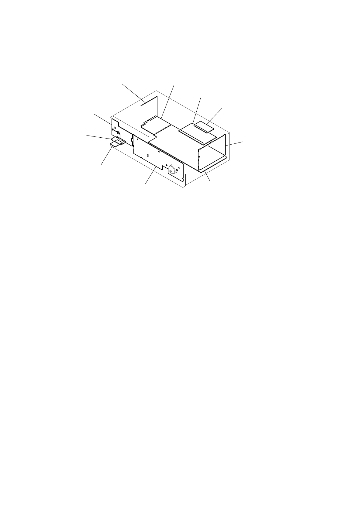
2. DISASSEMBLY
2-1. Case ..................................................................................... 8
2-2. Back Panel Section ............................................................. 9
2-3. Front Panel Section ............................................................. 9
2-4. DIGITAL Board ................................................................ 10
2-5. MAIN Board Section ........................................................ 10
2-6. STANDBY Board ............................................................. 11
3. TEST MODE .................................................................... 12
4. FM TUNER CHECK ...................................................... 13
5. DIAGRAMS
5-1. Block Diagram – Tuner/Audio Section – .......................... 15
5-2. Block Diagram – Digital Section – .................................... 16
5-3. Block Diagram – Video Section – ..................................... 17
5-4. Block Diagram – HDMI SW Section – ............................. 18
5-5. Block Diagram – Key/Display Section – .......................... 19
5-6. Block Diagram – Power Section – ....................................20
5-7. Printed Wiring Boards – Main Section – ........................... 22
5-8. Schematic Diagram – Main Section (1/3) – ......................23
5-9. Schematic Diagram – Main Section (2/3) – ......................24
5-10. Schematic Diagram – Main Section (3/3) – ......................25
5-11. Printed Wiring Board – Digital Section (1/2) – ................. 26
5-12. Printed Wiring Board – Digital Section (2/2) – ................. 27
5-13. Schematic Diagram – Digital Section (1/3) – .................... 28
5-14. Schematic Diagram – Digital Section (2/3) – .................... 29
5-15. Schematic Diagram – Digital Section (3/3) – .................... 30
5-16. Printed Wiring Board – Video Section – ........................... 31
5-17. Schematic Diagram – Video Section – .............................. 32
5-18. Printed Wiring Board – HDMI SW Section – ................... 33
5-19. Schematic Diagram – HDMI SW Section – ...................... 34
5-20. Printed Wiring Boards – DCAC, Power Section – ............ 35
5-21. Schematic Diagram – DCAC, Power Section – ................ 35
5-22. Printed Wiring Board – Display Section – ........................ 36
5-23. Schematic Diagram – Display Section – ........................... 37
5-24. Printed Wiring Boards – Power Section – ......................... 38
5-25. Schematic Diagram – Power Section – .............................39
6. EXPLODED VIEWS
6-1. Case Section ......................................................................50
6-2. Front Panel Section ............................................................ 51
6-3. Back Panel Section ............................................................ 52
6-4. Chassis Section .................................................................. 53
7. ELECTRICAL PARTS LIST ....................................... 54
4

• US, Canadian model
Getting Started
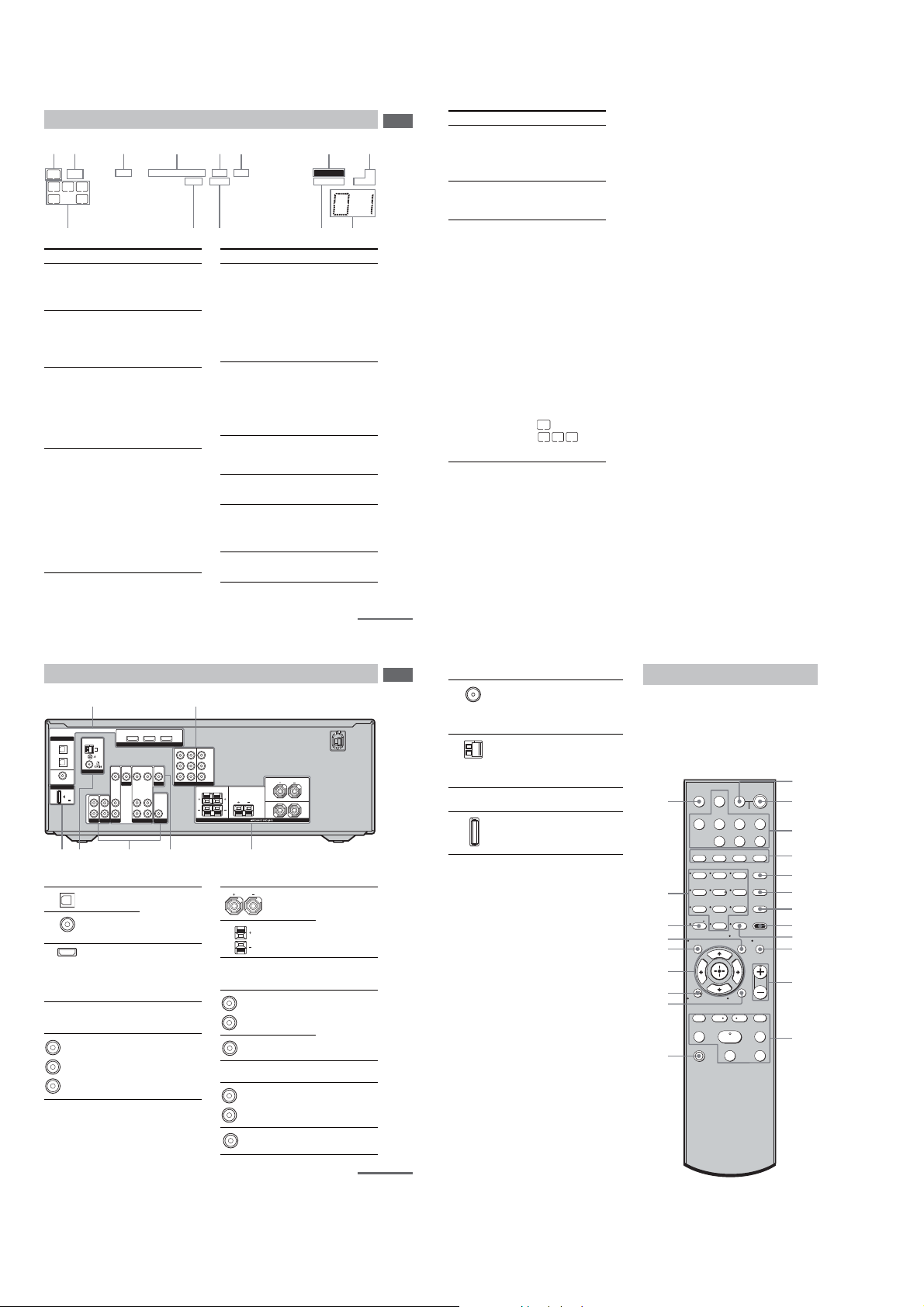
Description and location of parts
Front panel
3165274
SECTION 1
GENERAL
Name Function
Getting Started
L MEMORY/
ENTER
TUNING
MODE
TUNING +/–
M PHONES jack Connects to headphones
Press to operate the tuner
(FM/AM) (page 46).
(page 58).
STR-DG520
This section is extracted
from instruction manual.
?/1
SPEAKERS
(ON/OFF)
MEMORY/
TUNING
TUNING
PHONES
ENTER
Name Function
A ?/1
(on/standby)
B SPEAKERS
(ON/OFF)
C Display The current status of the
D Remote
sensor
E DISPLAY Press to select infor mation
F INPUT MODE Press to select the input mode
Press to turn the receiver on
or off (page 25, 29, 30, 45,
62).
Press to turn the speaker
system on or off (page 14).
selected component or a list
of selectable items appears
here (page 7).
Receives signals from remote
commander.
displayed on the display
(page 53).
when the same components
are connected to both digital
and analog jacks (page 50).
2CH A.F.D. MOVIE MUSIC
MODE
Name Function
G MASTER
VOLUME
H MUTING Press to turn off the sound
I ANALOG
DIRECT
J INPUT
SELECTOR
K 2CH Press to select a sound field
A.F.D.
MOVIE
MUSIC
• AEP, UK model
Getting Started
Description and location of parts
Front panel
3165274
?/1
SPEAKERS
(ON/OFF)
AUTO CAL MIC
PHONES
MEMORY/
TUNING
TUNING
ENTER
2CH A.F.D. MOVIE MUSIC
MODE
DISPLAY INPUT MODE
MASTER VOLUME
INPUT SELECTOR
ANALOG
DIRECT
Turn to adjust the volume
level of all speakers at the
same time (page 27, 28, 29,
30).
temporarily.
Press MUTING again to
restore the sound (page 28).
Press to listen to high quality
analog sound (page 45).
Turn to select the input
source to play back (page 28,
29, 30, 45, 46, 48, 49, 50, 52,
54).
(page 40).
continued
INPUT SELECTOR
ANALOG
DIRECT
MASTER VOLUME
DISPLAY INPUT MODE
MUTING
89qd q;qs qa
US
US
5
6
Name Function
Getting Started
L MEMORY/
ENTER
TUNING
MODE
Press to operate the tuner
(FM/AM) (page 50).
TUNING +/–
M AUTO CAL
MIC jack
N PHONES jack Connects to headphones
MUTING
Connects to the supplied
optimizer microphone for the
Auto Calibration function
(page 27).
(page 64).
Name Function
A ?/1
(on/standby)
B SPEAKERS
(ON/OFF)
C Display The current status of the
D Remote
sensor
E DISPLAY Press to select information
F INPUT MODE Press to select the input mode
Press to turn the receiver on
or off (page 25, 32, 33, 49).
Press to turn the speaker
system on or off (page 14).
selected component or a list
of selectable items appears
here (page 7).
Receives signals from remote
commander.
displayed on the display
(page 54, 58).
when the same components
are connected to both digital
and analog jacks (page 55).
89qf qd q;qs qa
Name Function
G MASTER
VOLUME
H MUTING Press to turn off the sound
I ANALOG
DIRECT
J INPUT
SELECTOR
K 2CH Press to select a sound field
A.F.D.
Turn to adjust the volume
level of all speakers at the
same time (page 30, 31, 32,
33).
temporarily.
Press MUTING again to
restore the sound (page 31).
Press to listen to high quality
analog sound (page 49).
Turn to select the input
source to play back (page 31,
32, 33, 49, 50, 52, 53, 55, 58,
59).
(page 44).
MOVIE
MUSIC
continued
GB
5
GB
6
5
STR-DG520
21
About the indicators on the display
1 2 3 4 5 6 87
PLII;PL OPT DTS MEMORY ST
LFE
SW
LCR
SL S SR
Name Function
A SW Lights up when sub woofer
B LFE Lights up when the disc being
C ; D Lights up when the receiver is
D ; PL/
; PLII
;D;
selection is set to “YES” (page
37) and the audio signal is
output from the SUB
WOOFER jack.
played back contains an LFE
(Low Frequency Effect)
channel and the LFE channel
signal is actually being
reproduced.
decoding Dolby Dig ital
signals.
Note
When playing a Dolby Digital
format disc, be sure that you
have made digital connections
and that INPUT MODE is set
to “AUTO” (page 50).
“; PL” lights up when th e
receiver applies Pro Logic
processing to 2 channel signals
in order to output the center and
surround channel signals.
“; PLII” lights up when the
Pro Logic II Movie/Music
decoder is activated.
However, these indicators do
not light up if both the center
and surround speakers are set to
“NO” (page 33) and you select
a sound field using the A.F.D.
button.
Name Function
E OPT Lights up when BD input is
F DTS Lights up whe n the receiver is
G MEMORY Lights up when a memory
H Tuner
indicators
I Preset
station
indicators
J D.RANGE Lights up when dynamic range
selected. However,
“UNLOCK” appears on the
display if no digital signal is
input through the OPTICAL
jack. “OPT” also lights up
when SAT input is selected if
INPUT MODE is set to
“AUTO” and the source signal
is a digital signal being input
through the OPTICAL jack.
decoding DTS signals.
Note
When playing a DTS format
disc, be sure that you have
made digital connections and
that INPUT MODE is set to
“AUTO” (page 50).
function, such as Preset
Memory (page 48), etc., is
activated.
Lights up when using the
receiver to tune in radio
stations (page 46), etc.
Lights up when using the
receiver to tune in radio
stations you have preset. For
details on presetting radio
stations, see page 47.
compression is activated (page
32).
Name Function
Getting Started
MONOD.RANGECOAXHDMI
9q;qaqsqd
K COAX Lights up when DVD input is
L HDMI Lights up when the receiver
M Playback
channel
indicators
L
R
C
SL
SR
S
selected. However,
“UNLOCK” appears on the
display if no digital signal is
input through the COAXIAL
jack.
recognizes a component
connected via a HDMI IN jack
(page 17).
The letters (L, C, R, etc.)
indicate the channels being
played back. The boxes around
the letters vary to show how the
receiver downmixes the so urce
sound (based on the speaker
settings).
Front Left
Front Right
Center (monaural)
Surround Left
Surround Right
Surround (monaural or the
surround components obtained
by Pro Logic processing)
Example:
Recording format (Front/
Surround): 3/2.1
Output channel: When
surround speakers are set to
“NO” (page 33)
Sound Field: A.F.D. AUTO
SW
LCR
SL SR
Rear panel
AM
ANTENNA
IN
IN
L
R
TV
SA-CD/CD
OPTICAL
IN jacks
COAXIAL IN
jack
HDMI IN/
OUT jacks*
COMPONENT
VIDEO
INPUT/
OUTPUT
jacks*
DVD IN BD IN OUT
VIDEO
VIDEO
VIDEO
IN
OUT
IN
DVD
AUDIO
AUDIO
OUT
IN
SAT VIDEO
HDMI
VIDEO
VIDEO
IN
OUT
MONITOR
AUDIO
AUDIO
IN
OUT
SUB WOOFER
47 6 5
Connects to a DVD
player, etc. The
COAXIAL jack
provides a better
sound quality (page
17, 20, 22).
Connects to a DVD
player or a Blu-ray
disc player. The
image and the
sound are output to
a TV (page 17).
Connects to a DVD
player, TV, or a
satellite tuner. You
can enjoy high
quality image (page
19, 20, 22).
DIGITAL
OPTICAL
BD
IN
SAT
IN
DVD
IN
COAXIAL
DMPORT
DC5V
0.7A MAX
A DIGITAL INPUT/OUTPUT section
B COMPONENT VIDEO INPUT/
OUTPUT section
Green
(Y)
Blue
(P
B/CB)
Red
(P
R/CR)
SAT IN
DVD IN MONITOR OUT
Y
P
B/CB
PR/C
R
COMPONENT VIDEO
SURROUND CENTER
LR
SPEAKERS
3
C SPEAKERS section
D VIDEO/AUDIO INPUT/OUTPUT
section
White (L)
Red (R)
Yellow
E AUDIO INPUT section
White (L)
Red (R)
Black
FRONT
L
R
AUDIO IN/
OUT jacks
VIDEO IN/
OUT jacks*
AUDIO IN
jacks
AUDIO OUT
jack
continued
Connects to
speakers (page 14).
Connects to video
and audio jacks of a
VCR, a DVD
player, etc. (page
19–23).
Connects to a Super
Audio CD player,
CD player, etc.
(page 15).
Connects to a sub
woofer (page 14).
continued
US
7
Getting Started
US
9
US
8
F ANTENNA section
FM
ANTENNA
jack
AM
ANTENNA
terminals
Connects to the FM
wire antenna
(aerial) supplie d
with this receiver
(page 24).
Connects to the AM
loop antenna
(aerial) supplie d
with this receiver
(page 24).
G DMPORT
DMPORT
jack
* You can watch the selected input image when you
connect the HDMI OUT or MONITOR OUT jack
to a TV or projector (page 17, 19).
Connects to a
DIGITAL MEDIA
PORT adapter
(page 51).
Remote commander
You can use the supplied remote to operate the
receiver and to control the Sony audio/video
components that the remote is assigned to
operate (page 54).
RM-AAU020
wa
w;
ql
qk
qj
qh
qg
qf
qd
TV INPUT
TV
?/1
AV
?/1
SLEEP DMPORT
SYSTEM STANDBY
VIDEO BD DVD SAT
TV TUNER
SA-CD/CD
2CH A.F.D.
MOVIE MUSIC
123
46
5
9
78
>10/
MEMORY AMP MENU
0/10
ENTER
-
CLEAR
TOOLS/
OPTIONS
MENU/HOME
RETURN/EXIT
TV CH –
REPLAY ADVANCE
PRESET –
.
TUNING –
<
<
HMm
TV
X
?/1
DVD/BD
MENU
D.SKIP
D.TUNING
GNITUMYALPSID
TV VOL
MASTER VOL
TV CH +
PRESET +
>
TUNING +
FM MODE
x
1
2
3
4
5
6
7
8
9
q;
qa
qs
US
10
6

STR-DG520
Name Function
A TV ?/1
(on/standby)
AV ?/1
(on/standby)
B ?/1
(on/standby)
C Input buttons Press one of the buttons to
D 2CH Press to select a sound field.
A.F.D.
MOVIE
MUSIC
E DVD/BD
MENU
D.SKIP Press to skip a disc when
F
G D.TUNING Press to e n t er direct tuning
Press TV ?/1 and TV (M) at
the same time to turn the TV
on or off.
Press to turn on or off the
Sony audio/video components
that the remote is assigned to
operate (page 54).
If you press ?/1 (B) at the
same time, it will turn off the
receiver and other
components (SYSTEM
STANDBY).
Note
The function of the AV ?/1
switch changes automatically
each time you press the input
buttons (C).
Press to turn the receiver on or
off.
To turn off all components,
press ?/1 and AV ?/1 (A) at
the same time (SYSTEM
STANDBY).
select the component you
want to use. When you press
any of the input buttons, the
receiver turns on. The buttons
are factory assigned to control
Sony components.
You can change the button
assignments following the
steps in “Changing button
assignments” on page 54.
Press to display the menu of
the DVD or Blu-ray disc on
the TV screen. Then, use V,v,
B, b and (P) to perform
menu operations.
using a multi-disc changer.
mode.
Name Function
H AMP MENU Press to display the menu of
I MEMORY Press to store a station.
ENTER Press to enter the value after
J MUTING Press to turn off the sound
K TV VOL
a)
+
MASTER
VOL +
L ./>
REPLAY /
ADVANCE
m/M
H
X
/–
a)
/–
b)
<
b)
a)b)
b)
the receiver. Then, use V, v,
B, b and (P) to perform
menu operations.
selecting a channel, dis c or
track using the numeric
buttons of the TV, VCR or
satellite tuner.
temporarily.
Press MUTING again to
restore the sound.
Press MUTING and TV (M)
at the same time to activate
the TV’s muting function.
Press TV VOL +/– and TV
(M) at the same time to adjust
the TV volume level.
Press to adjust the volume
level of all speakers at the
same time.
Press to skip a track of the CD
player, DVD player or Bluray disc player.
Press to replay the previous
<
scene or fast forward the
current scene of the VCR,
DVD player or Blu-ray disc
player.
Press to
– search tracks in the forward/
reverse direction of the
DVD player.
– start fast forward/rewin d of
the VCR, CD player or Bluray disc player.
Press to start playback of the
VCR, CD player, DVD player
or Blu-ray disc player.
Press to pause playback or
recording of the VCR, CD
player, DVD player or Bluray disc player. (Also starts
recording with components in
recording standby.)
Getting Started
Name Function
b)
x
FM MODE Press to select the FM
TV CH +/– Press TV CH +/– and TV (M)
PRESET +/– Press to select
Press to stop playback of the
VCR, CD player, DVD pla yer
or Blu-ray disc player.
monaural or stereo reception.
at the same time to select
preset TV channels.
– preset stations.
– prese t channels of the VCR
or satellite tuner.
TUNING +/– Press to scan a station.
M TV Press TV and the button you
N MENU/HOME Press to display the menu of
O RETURN/
EXIT O
want at the same time to
activate the buttons with
orange printing.
the VCR, DVD player,
satellite tuner or Blu-ray disc
player on the TV screen.
Press MENU/HOME and TV
(M) at the same tim e to
display the TV’s menu.
Then, use V, v, B, b and
(P) to perform menu
operations.
Press to
– return to the previous menu.
– exit the menu while the
menu or on-screen guide of
the VCR, DVD player,
satellite tuner or Blu-ray disc
player is displayed on t he
TV screen.
Press RETURN/EXIT O and
TV (M) at the same time to
return to the previous menu or
exit the TV’s menu while the
menu is displayed on the TV
screen.
Name Function
P
V/v/B/b
Q DISPLAY Press to select information
R TOOLS/
OPTIONS
S -/-- Press to select the channel
>10/
CLEAR Press to clear a mistake when
After pressing DVD/BD
,
MENU (E), AMP MENU
(H) or MENU/HOME (N),
press V,v, B or b to select the
settings. Then, p ress to
enter the selection if you have
pressed DVD/BD MENU or
MENU/HOME previously.
Press also to enter the
selection of the receiver,
VCR, satellite tuner, CD
player, DVD player or Bluray disc player.
displayed on the TV scree n of
the VCR, satellite tuner, CD
player, DVD player or Bluray disc player.
Press DISPLAY and TV (M)
at the same time to di s p lay
TV’s information on the TV
screen.
Press to display and select the
options of the DVD player or
Blu-ray disc player.
Press TOOLS/OPTIONS and
TV (M) at the same time to
display options applicable to
the Sony TV.
entry mode, either one or two
digit of the VCR.
Press -/-- and TV (M) at the
same time to selec t the
channel entry mode, either
one or two digits of the TV.
x
Press to select
– track numbers over 10 of the
– channel numbers of the
you press the incorrect
numeric button.
VCR, satellite tuner or CD
player.
Digital CATV terminal.
Name Function
T Numeric
buttons
(number 5
U TV INPUT Press TV INPUT and TV (M)
SLEEP Press to activate the Sleep
a)
The number 5, MASTER VOL +, TV VOL +, and
H buttons have tactile dots. Use the tactile dots
as references when operating the receiver.
b)
This button is also available for DIGITAL
MEDIA PORT adapter operation. For details on
the function of the but ton, see the opera t ing
instructions supplied with the DIGITAL MEDIA
PORT adapter.
Notes
•Some functions explained in this section may not
work depending on the model.
• The above explanation is intended to serve as an
example only. Therefore, depending on the
component, the above operation may not be
possible or may operate differently than described.
Press to
– preset/tune to preset
a)
)
stations.
– select track numbers of the
CD player, DVD player or
Blu-ray disc player. Press 0/
10 to select track number 10.
– select channel numbers of
the VCR or satellite tuner.
Press the numeric buttons and
TV (M) at the same time to
select the TV channels.
at the same time to select the
input signal (TV input or
video input).
Timer function and the
duration which the receiver
turns off automatically.
continued
US
11
US
12
Getting Started
US
13
7
STR-DG520
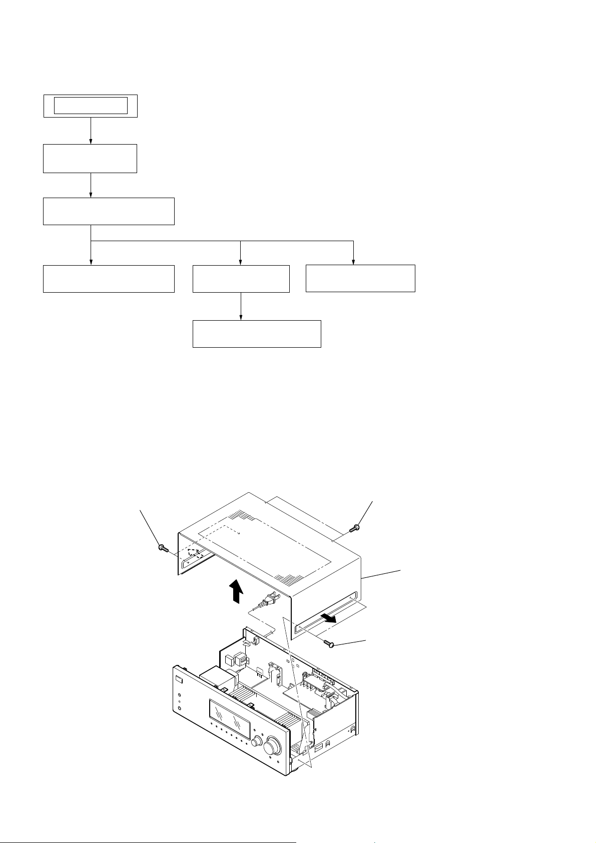
SECTION 2
DISASSEMBLY
Note: This set can be disassemble according to the following sequence.
SET
2-1. CASE
(Page 8)
2-2. BACK PANEL SECTION
(Page 9)
2-3. FRONT PANEL SECTION
(Page 9)
Note:
Follow the disassembly procedure in the numerical order given.
2-1. CASE
two screws
(+BVST 4 × 8) (black)
two screws
(+BVTT 4 × 8) (silver)
2-4. DIGITAL BOARD
(Page 10)
2-5. MAIN BOARD SECTION
(Page 10)
2-6. STANDBY BOARD
(Page 11)
two screws
(+BVTP 3 × 8)
case
two screws
(+BVST 4 × 8) (black)
two screws
(+BVTT 4 × 8) (silver)
8
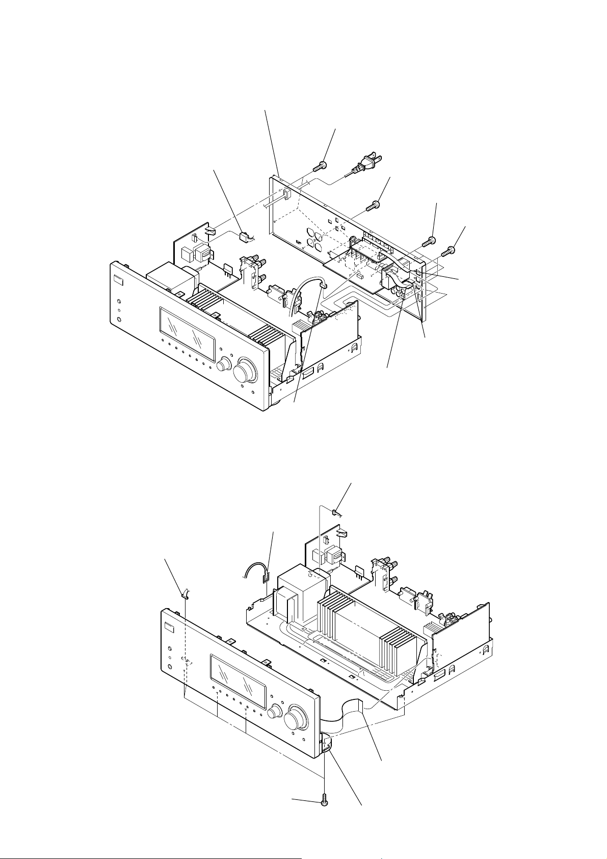
2-2. BACK PANEL SECTION
STR-DG520
back panel section
six screws
(+BVTP 3 × 8)
CNP901 (2P)
2-3. FRONT PANEL SECTION
CNP203 (4P)
five screws
(+BVTP 3 × 8)
three screws
(+BVTP 3 × 8)
three screws
(+BVTP 3 × 8)
wire (flat type) (9 core)
(CNS510)
wire (flat type) (7 core)
(CNS509)
wire (flat type) (9 core)
(CNS507) (US, CND)
wire (flat type) (11 core)
(CNS508) (AEP, UK)
CNP790 (4P)
CNP910 (3P)
clip
wire (flat type) (17 core)
(CNS513)
five screws
(+BVTP 3 × 8)
front panel section
9
STR-DG520
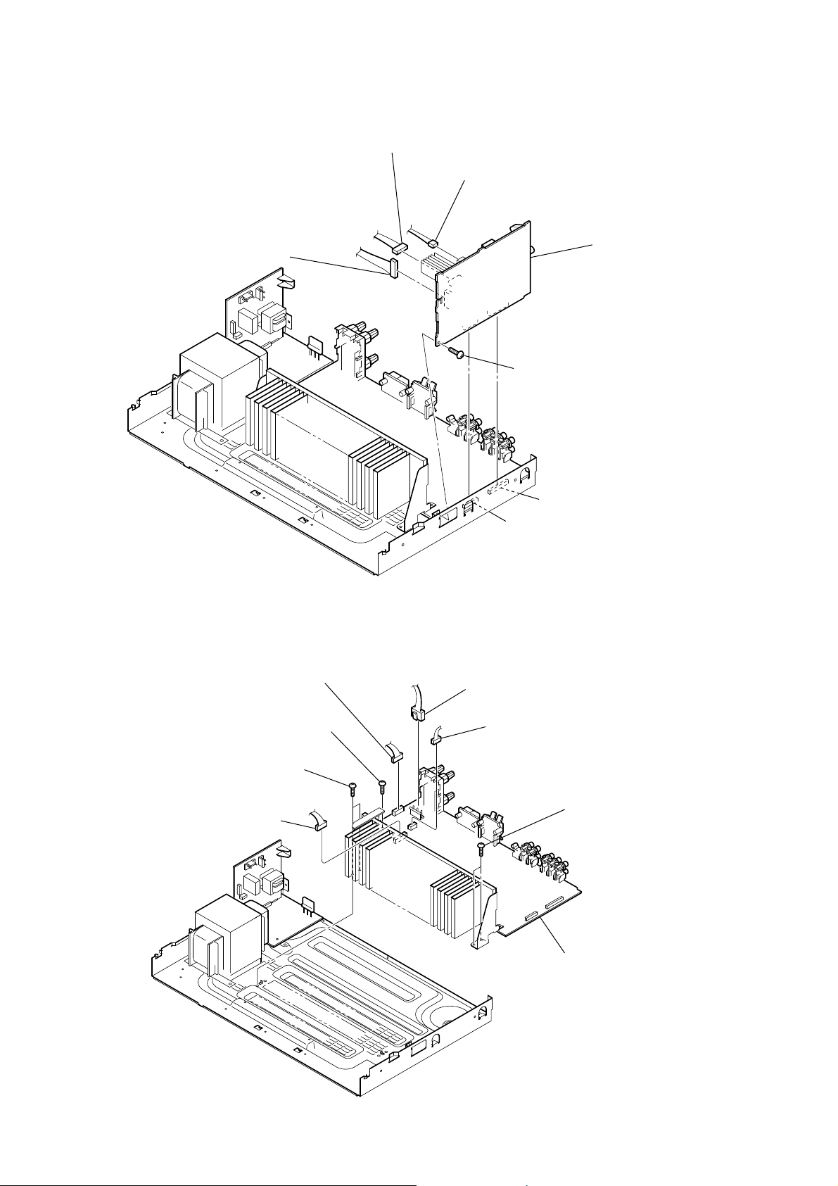
2-4. DIGITAL BOARD
CNP505 (9P)
CNP512 (3P)
CNP503 (6P)
2-5. MAIN BOARD SECTION
DIGITAL board
screw
(+BVTP 3 × 8)
CNP411
CNP410
screw
(+BV3 (3-CR))
two screws
(+BV3 (3-CR))
CNP912 (6P)
CNP940 (6P)
CNP921 (3P)
CNP930 (3P)
two screws
(+BV3 (3-CR))
MAIN board section
10
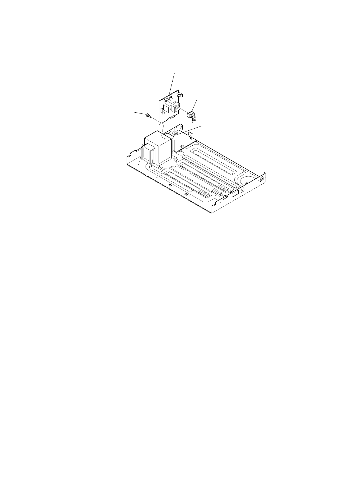
2-6. STANDBY BOARD
screw
(+BVTP 3 × 8)
STR-DG520
STANDBY board
CNP902 (2P)
CN4001
11
STR-DG520
SECTION 3
TEST MODE
AM CHANNEL STEP 9 kHz/10 kHz SELECTION MODE
(US, Canadian model only)
* Either the 9 kHz step or 10 kHz step can be selected for the AM
channel step.
* Procedure:
Turn the [INPUT SELECTOR] control to set AM and press the
[
] button to turn off the main power.
?/1
While depressing the [TUNING MODE] button, press the [
?/1
button to turn on the main power.
Either the message “9k STEP” or “10k STEP” appears for a moment and select the desired step.
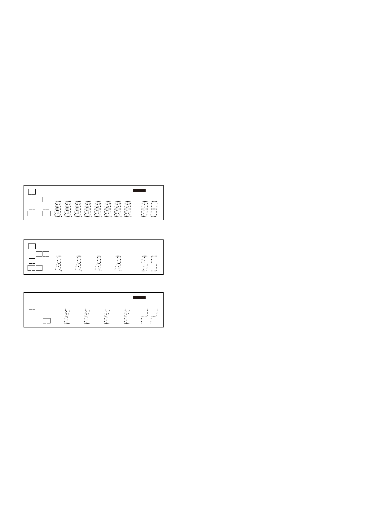
VACUUM FLUORESCENT DISPLAY TEST MODE
* All fl uorescent segments are tested.
When this test is activated, all segments light on at the same time,
then each segment lights on one after another.
* Procedure:
While depressing the [TUNING MODE] and the [DISPLAY]
buttons simultaneously, press the [
] button to turn on the
?/1
main power.
1. ALL segments light on.
SW
LFE
L
CR
SL S SR
SBL SB SBR
DDD
DEX DTS-ESxIIPL RDS STCAT96/24
SP B
D
HDMI
D
PL OPT
MEMORY
NEO:6COAX
SAT
D.RANGE
dB
Hzk
ft.m
MHz
MONO
SPA
D
2. Turn the [INPUT SELECTOR] control, confi rm display.
LFE
L R
S
SP B
x RDS
NEO:6COAX
D.RANGE
k
m
MHz
MONO
3. Turn the [INPUT SELECTOR] control, confi rm display.
SW
C
SL SR
SBL SB SBR
D
D
D DTS STCAT
D
D
PL
MEMORY
dB
Hz
ft.
KEY CHECK MODE
* Button check
* Procedure:
While depressing the [SPEAKERS (ON/OFF)] and the [2CH]
buttons simultaneously, press the [
] button to turn on the
?/1
main power.
Either the message “REST 13” appears.
]
Every pressing of any button other than the [
?/1
the buttons. The buttons which are already counted once are not
counted again. When all buttons are pressed “REST 00” appears.
SWAP ALL MODE
* The signal will be swap to all channel so that all speaker will
have sound output.
* Procedure:
1. While depressing the [SPEAKERS (ON/OFF)] and the
[A.F.D.] buttons simultaneously, press the power [
to turn on the main power.
2. “SWAP” appears. (No change while displayed.)
SHIPMENT MODE
All preset contents are reset to the default setting.
* Procedure:
1. While depressing the [SPEAKERS (ON/OFF)] and the [MUSIC] buttons simultaneously, press the power [
?/1
turn on the main power.
2. “CLEARED” appears and switch off the set.
RE-BOX CLASSIFICATION TEST MODE
* Procedure:
1. While pressing the [MEMORY/ENTER] and the [INPUT
MODE] buttons simultaneously, press the power [
to turn on the main power.
2. “R.BOX[][][]xxx” appears.
3. xx indicates number of times set powered on.
4. Press any button or power off the set to release test mode.
] counts down
] button
?/1
] button to
] button
?/1
4. Turn the [INPUT SELECTOR] control, all segments light off.
SOUND FIELD CLEAR MODE
* The preset sound fi eld is cleared when this mode is activated.
Use this mode before returning the product to clients upon completion of repair.
* Procedure:
While depressing the [2CH] button, press the [
] button to turn
?/1
on the main power.
The message “S.F . CLR.” appears for a moment and initialization
is performed.
SOFTWARE VERSION DISPLAY MODE
* The software version is displayed.
* Procedure:
While depressing the [SPEAKERS (ON/OFF)] and the [DISPLAY] buttons simultaneously, press the [
] button to turn on
?/1
the main power.
The model name, destination and the software version are displayed for a moment.
12
STR-DG520
SECTION 4
FM TUNER CHECK
DCAC FACTORY TEST MODE (AEP, UK model only)
DCAC Factory Test mode have two stages:
1. DCAC DSP Data Line Checking
2. DCAC board Checking
Start Pass Pass
DSP Data Line
Check
Factory Test System Setup
Receiver
DCAC MIC
SPK Front Left
1. When power off:
Press the three buttons [MEMORY/ENTER] + [MOVIE] +
[
] .
?/1
“DCAC[]FTM” appears.
Afterward, press the [TUNING MODE] to start DCAC factory
test mode.
1. DCAC DSP Data Line Checking
After press the [TUNING MODE], DCAC Factory test mode will
start, below display will show:
“DCAC
[][][]x” x=1, 2, 3
If there is error happen, below display will show:
Auto Cal Mic
Check
END
FM AUTO STOP CHECK
generator
set
OUT (75 Ω)
Procedure:
1. Turn on the set.
2. Input the following signal from Signal Generator to FM
antenna input directly.
* Carrier Frequency: A=87.5 MHz, B=98 MHz, C=108 MHz
Deviation : 75 kHz
Modulation : 1 kHz
ANT input : 35 dBu (EMF)
Note:
Please use 75 ohm “coaxial cable” to connect SG and the set. You
cannot use video cable for checking.
Please use SG whose output impedance is 75 ohm.
3. Set to FM tuner function and scan the input FM signal with
automatic scanning.
4. Confi rm that input Frequency of A, B and C are detected and
automatic scanning stops.
The stop of automatic scanning means “The station signal is received in good condition.”
[]SD0x” x=1 t D1501 or R1530 problem
“ERR
x=2 t D1503 problem
x=3 t D1504 problem
2. DCAC board Checking
Connect front left speaker of the receiver and AUTO CAL microphone. Turn [MASTER VOLUME] jog, there will be test tone
sound output from front left speaker, and the display will change
accordingly.
“AD[]-[]xxx” xxx=0 to 255 (depends on loudness of test tone)
13
STR-DG520
• Circuit Boards Location
SECTION 5
DIAGRAMS
POWER board
DCAC board
(AEP, UK model only)
HEADPHONE board
STANDBY board
DISPLAY board
DCDC CONVERTER board
VIDEO board
HDMI SW board
DIGITAL board
MAIN board
14
STR-DG520
STR-DG520
1515
C-CH
SR-CH
R-CH
SL-CH
L-CH
FR-IN
FL-IN
R-CH
SW
SEL
C
SEL
SL
SEL
R-CH
R-CH
R-CH
DIR
FUNCTION SELECT
IC400
VCCVEE
+7V
SEL
SW
MCU
I/F
-7V
SW OUT
C OUT
SL OUT
FL OUT
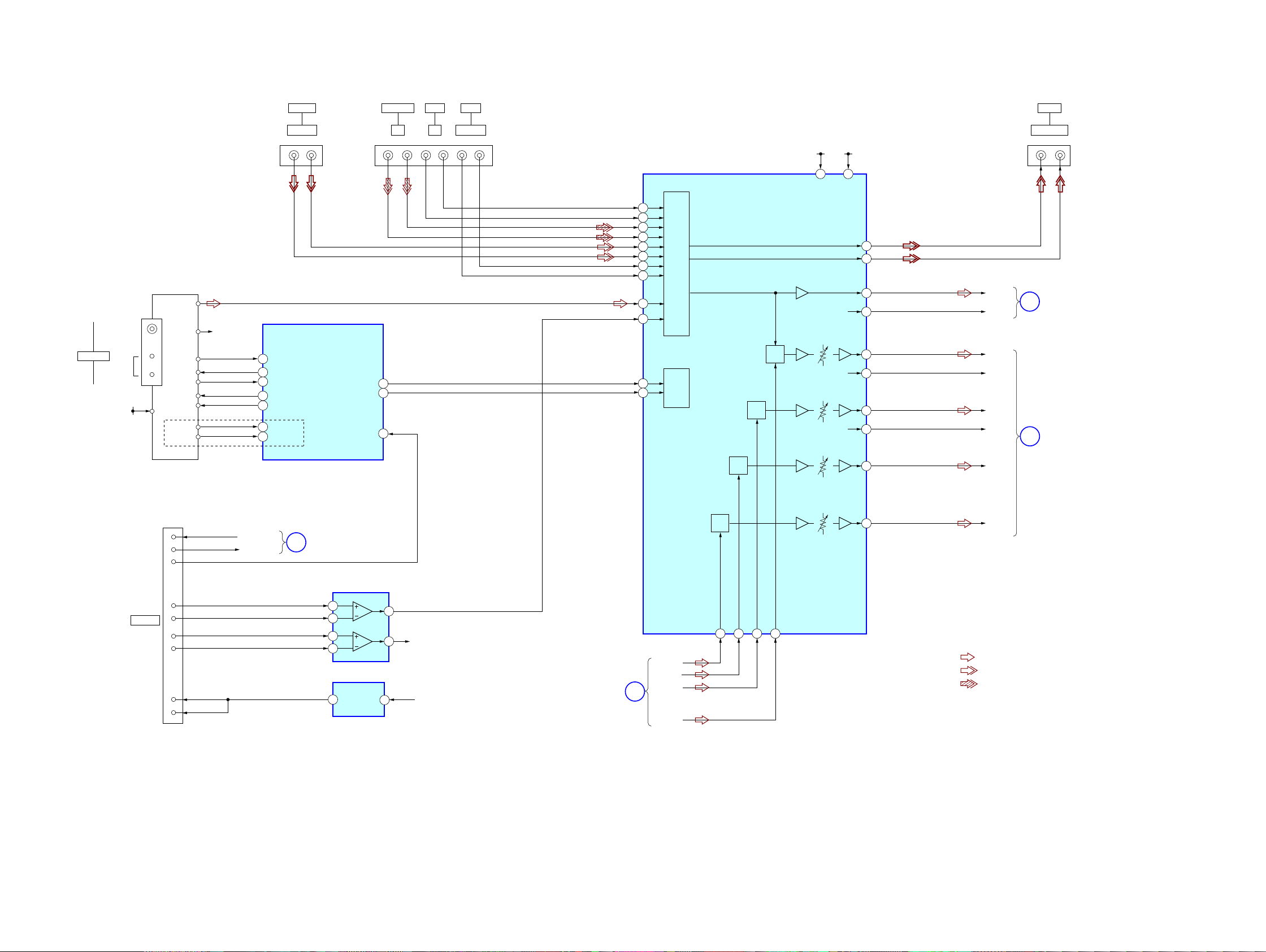
• Signal path
: TUNER (FM/AM)
: VIDEO (AUDIO)
: CD (ANALOG)
• R-ch is omitted due to
same as L-ch.
43
92
89
AUDIO IN
LR
VIDEO
TV
AM
TN1
FM/AM TUNER UNIT
SYSTEM
CONTROL
IC1101 (1/6)
SA-CD/CD
LRLR
J404 (1/2)
J402
R-CH
SLATCH
AEP,UK MODEL
91
TUNER_DATA
90
TUNER_CLK
VOL_IC_DATA
VOL_IC_CLK
TUNER SD
DO/SD/ST
L-CH
R-CH
SD
CE
DO
DI
CL
TU+9V
24
DMPORT AMP
IC3002
25
DMPORT_DET
26
FM 75Ω
COAXIAL
ANTENNA
-1 -2 -3 -4 -5 -6-3 -4
52
RDS_CLK
RDS INT
53
RDS_DATA
RDS DATA
63
AUDIO OUT
LR
J404 (2/2)
VIDEO
-1 -2
IN IN
SAT
LR
AUDIO IN
12 8
10
11
75
14
13
18
17
SW-CH
16
71 70 68 72
48
47
52
51
39
38
44
43
15
76
27
28
L
SEL
DMPORT_RX
DMPORT_TX
DMPORT_RX
DMPORT_TX
J1302
DC5V
0.7A MAX
DMPORT
5
6
DET
7
L+
13
L–
11
DBUS+5V
2
3
2
1
R+
14
R–
12
5
6
7
+5.8V
4
2
61
+5V REG
IC1906
VIDEO+5V
4
DIGITAL
SECTION
B
DIGITAL
SECTION
A
DISPLAY
SECTION
D
POWER
SECTION
C
5-1. BLOCK DIAGRAM – TUNER/AUDIO Section –
(Page 19)
(Page 16)
(Page 20)
(Page 16)

STR-DG520
STR-DG520
1616
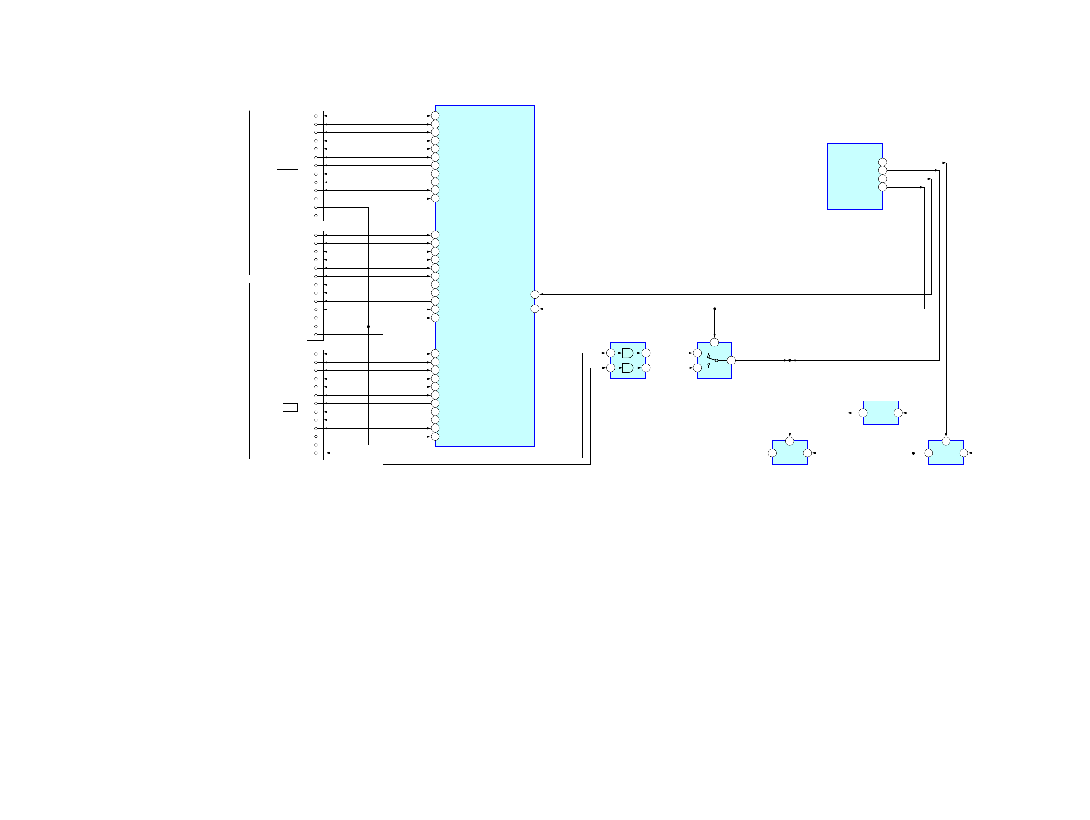
5-2. BLOCK DIAGRAM – DIGITAL Section –
• Signal path
: TUNER (FM/AM)
: VIDEO (AUDIO)
: DVD (DIGITAL)
• R-ch is omitted due to
same as L-ch.
DSPIB
AEP,UK MODEL
DPSOA_DAI_P6
DPSOC_DAI_P8
DPSOB_DAI_P7
DOUT
9
79
DSPIA
78
NONAUDIO
AUDIO
24
XMCK
20
CKOUT
13
97
DPFSCK
94
BCK IN
BCK
14 89
LRCK IN
LRCK
15 88
DATAO
64
70
65
X1302
25MHz
X1301
12.288MHz
CLKIN
142
XTAL
143
BCK OUT
87
LRCK OUT
86
99 20 188 19
FLAG1
ERROR
21
22
SCKI6BCK8LRCK
7
95 96 97 98
38 37 36 35 47 17
INPUT
DATA
DEMODULATOR
Pa,Pb DETECTION LOCK
DETECTION
MICROPROCESSOR
I/F
C bit DETECTION
34 16
16
DVD
IN
DIGITAL
(COAXIAL)
1
BD IN
(OPTICAL)
OUT
OPTICAL
RECEIVER
IC1352
IC1303
DIGITAL AUDIO
I/F RECEIVER
IC1301
J1301
23
WAVE
SHAPER
IC1903
13
+3.3V
REG
IC1905
13
+3.3V
REG
IC1002
13
+1.2V
REG
SWITCH
IC1014
51
+1.2V
VDDI
+3.3V-2
VDDE
+3.3V
DIR
VDD
FL-IN
+3.3V
+3.3V-2
+1.2V
+5.8V
DIGITAL
DECIM.
FILTER
ADC
IC1401
DSP EX3
IC1501
ERROR
1
DATAO
DSP SPIDS
DSP SPICLK
DSP INT
MISO
MOSI
CLK
CE
DI
DO
XSTATE
CLKCEDI
DO
CKSEL1
93100
48
XMODE
94
CKSEL1
XMODE
XSTATE
5
3
XOUT
DIN2
DIN0
1
SAT
IN
(OPTICAL)
OUT
OPTICAL
RECEIVER
IC1351
4
DIN1
XIN
D1301
D1501
SYSTEM
CONTROL
IC1101 (2/6)
TUNER/
AUDIO
SECTION
B
TUNER/
AUDIO
SECTION
A
$3
MOD.
XRST
1114
1215
MUTE
57
DCAC_INT
MDI
MC
ML
MUTE
ML
12
13
MC
13
14
MD
DIN3
FL OUT
R-CH
VO3L
VO3R
VO1L
VO1R
VO2L
VO2R
9
26
25
8
7
2
MCK
3
BCK
LRCK
4
6CH DAC
IC1452
DAC
DIN1
SL OUT
R-CH
22
21
DAC
DIN2
C OUT
23
SW OUT
24
DAC
1
VIN L
FR-IN
2
VIN R
D1503
D1504
CK Q
DAC
125 126121 127 15122
SPIDS
RESET
SPICLK
FLAG0
MISO
MOSI
4721
(Page 15)
(Page 15)
STR-DG520
STR-DG520
1717
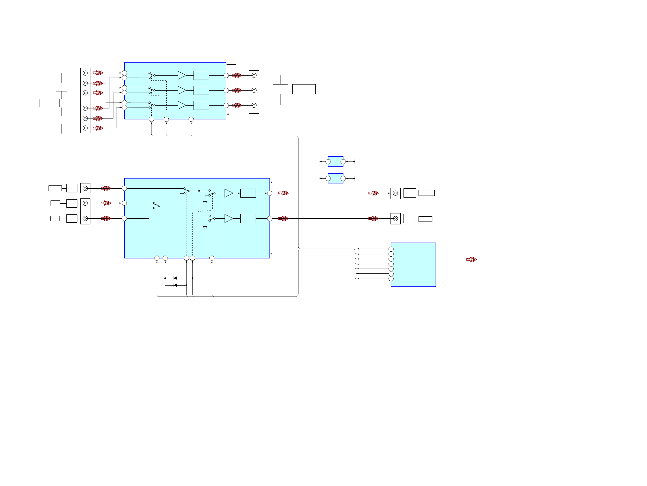
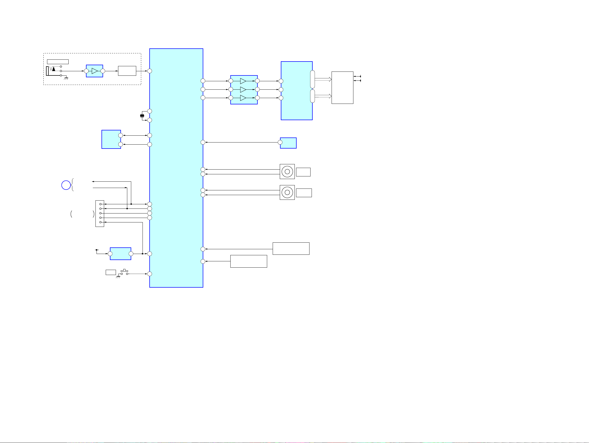
5-3. BLOCK DIAGRAM – VIDEO Section –
1
CH1 IN1
CH2 IN1
CH3 IN1
CH1 IN2
CH2 IN2
CH3 IN2
CHI OUT
CH2 OUT
CH3 OUT
3
8
10
17
15
2 4
Y
P
B/CB
PR/CR
Y
SW1 SW2
COMPONENT
SW1
COMPONENT
SW2
P
B/CB
PR/CR
J220 (1/2)
J210 (1/2)
24
75Ω
DRIVER
6dB AMP
22
75Ω
DRIVER
6dB AMP
20
75Ω
DRIVER
6dB AMP
23
PS
PS(V-MUTE)
6 14 4
13
J211 (1/2)
5
3
DVD
IN
SAT
IN
VIDEO
IN
VIDEO
IN
COMPONENT
VIDEO
-4
-5
-6
-1
-2
-3
Y
P
R/CR
PB/CB
J220 (2/2)
MONITOR
OUT
COMPONENT
VIDEO
-7
1
75Ω
DRIVER
6dB AMP
15
3 1
75Ω
DRIVER
6dB AMP
-2
J210 (2/2)
J211 (2/2)
-8
-9
-1
VIDEO
SAT
DVD
-1
VIDEO
IN
-2
VIDEO
OUT
VIDEO
-3
VIDEO
OUT
MONITOR
+5V
REG
IC201
+5V-3
3 2
-5V
REG
IC202
-5V-3
COMP_S1
COMP_S2
V_SW2
V_SW3
V_MUTE
V_SW1
COMPONENT SW1
COMPONENT SW2
COMPOSITE SW2
COMPOSITE SW3
COMPOSITE SW4
PS(V-MUTE)
COMPOSITE SW1
SYSTEM CONTROL
IC1101 (3/6)
-5V
-5V-3
+5V
+5V-3
+15V
-15V
VOUT1
VOUT2
V-1,-2
-5V-3
V+1,+2
+5V-3
VIN1
VIN4
VIN5
COMPOSITE SW4
COMPOSITE
SW1
COMPOSITE SW2
COMPOSITE SW3
SW4
D211
D210
SW1
2
SW5
10
SW2
SW3
INPUT SELECT
IC210
COMPONENT VIDEO SELECT
IC220
4
3
2
5
6
7
V_SW4
9
• Signal path
: VIDEO
STR-DG520
STR-DG520
1818
5-4. BLOCK DIAGRAM – HDMI SW Section –
HDMI_CTRL
HDMI_DET
HDMI_OEB
HDMI_SI
SYSTEM CONTROL
IC1101 (4/6)
87
88
86
34
77
A24
DATA2+
DATA2–
DATA1+
DATA1–
DATA0+
DATA0–
CLOCK+
CLOCK–
SCL (5V)
SDA (5V)
HOT PLUG DET
CEC
+5V POWER
DATA2+
DATA2–
DATA1+
DATA1–
DATA0+
DATA0–
CLOCK+
CLOCK–
SCL (5V)
SDA (5V)
HOT PLUG DET
CEC
+5V POWER
DATA2+
DATA2–
DATA1+
DATA1–
DATA0+
DATA0–
CLOCK+
CLOCK–
SCL (5V)
SDA (5V)
HOT PLUG DET
CEC
+5V POWER
CN5001
DVD IN
4
6
1
3
7
9
10
12
15
16
19
13
18
B24
A23
B23
A22
B22
A21
B21
SCL2
76
74
73
71
70
68
67
64
15
A14
B14
A13
B13
A12
B12
A11
B11
OEB
S1
14
12
11
9
8
6
5
SCL1
SDA1
3
2
HPD1
80
25
Y4
Z4
Y3
Z3
Y2
Z2
Y1
Z1
26
28
29
31
32
34
35
SCL SINK
SDA SINK
38
39
HPD SINK
40
SDA2
HPD2
63
62
CN5002
4
6
1
3
7
9
10
12
15
16
19
13
18
CN5003
4
6
1
3
7
9
10
12
15
16
19
13
18
1
LEVEL SHIFT
IC5004
HDMI RECEIVER/TRANSCEIVER
IC5001
ANALOG SWITCH
IC5005
5
4 5
3
7
1
6
3
4
42
21
1
POWER
CONTROL
4 2
1
+5.8V
REG
3 1
+3.3V
REG
IC5003
IC5006
HDMI+3.3V
+7V (VCC)
IC5002
OUT
BD IN
HDMI
STR-DG520
STR-DG520
1919
5-5. BLOCK DIAGRAM – KEY/DISPLAY Section –
83
FL DISPLAY DRIVER
IC100
14
I
29
•
31
82
29
30
5
6
65
64
54
SW NETWORK
S101-107,124
RV102
MASTER
VOLUME
56
51
49
28
27
77
+3.3V
(STBY)
X1
X0
SDA
38
DCAC_IN
AEP,UK MODEL
SCL
POWER_KEY
FLASH1/DMPORT_TX
FLASH2/DMPORT_RX
MD2
MD0
RSTX
SDA
SCL
EEPROM
IC1131
X1101
24MHz
SIRCS
F1
F2
75
FL_DATA
7
DIN
76
FL_LAT
9
STB
74
FL_CLK
8
CLK
GRID1
I
GRID11
SEG1
I
SEG17
VOL_ENCODER(A)
VOL_ENCODER(B)
ENC_A
DMPORT_RX
DMPORT_TX
ENC_B
A/D2
SW NETWORK
S108-111,120
A/D1
2
3
31
32
RV101
INPUT
SELECTOR
2
3
2
REMOTE
CONTROL
SIGNAL
RECEIVER
IC103
OUT
SIRCS
SYSTEM
CONTROL
IC1101 (5/6)
BUFFER
IC101
CNS504
S153
@
FLASH2
MD2
MD0
RESET
5
6
FLASH1
8
9
3
FLASH
PROGRAMMING
12
39
40
FL101
VACUUM
FLUORESCENT
DISPLAY
IC1111
RESET
42
I
32
9
4
2
8
6
3
15
MIC AMP
IC2000
DETECT
D2013,2014
AUTO CAL MIC
J2000
TUNER/AUDIO
SECTION
D
(Page 15)
STR-DG520
STR-DG520
2020
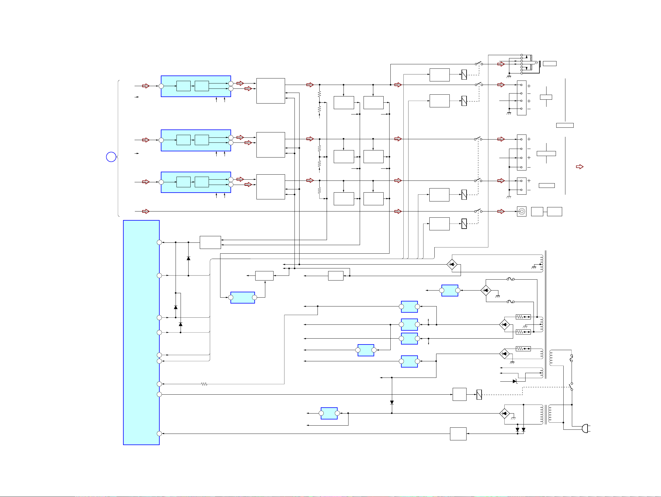
5-6. BLOCK DIAGRAM – POWER Section –
6
2
3
DRIVE
POWER AMP
Q701-704
CURRENT
DETECT
Q711,712
RY350
PRE DRIVER
IC701
IN 1
+VOUT1
-VOUT1
R
L
L
AUDIO
OUT
SUB
WOOFER
CENTER
SURROUND
R
R-CH
R-CH
L-CH
R-CH
SL-CH
C-CH
R-CH
SR-CH R-CH
TUNER/
AUDIO
SECTION
C
RY901
D920
F1
F2
-20V
+3.3V
(STBY)
+7V
(VCC)
+5V
-7V
+7V
TU+9V
-20V
RECT
D950-953
D990 D991
D1001
D1108
D1107
OVERLOAD
DETECT
D720,Q720
8
61
12
11
DRIVE
POWER AMP
Q651-654
CURRENT
DETECT
Q661,662
-20V REG
Q930
B-SWITCH
Q500,501
RELAY
DRIVER
Q901
AC IN
DETECT
Q990
PRE DRIVER
IC601
IN 2
+VOUT2
-VOUT2
OVERLOAD
DETECT
D670,Q670
6
2
3
DRIVE
POWER AMP
Q801-804
CURRENT
DETECT
Q811,812
PRE DRIVER
IC801
IN 1
+VOUT1
-VOUT1
OVERLOAD
DETECT
D820,Q820
RY355
RY301
70
PROTECTOR
D320,325-327
Q320,321,325
58
48
D1111
+9V
(STBY)
OVERLOAD
DETECT AMP
72
IC565
–55V
-B
+A5V
+5V
REG
13
IC1001
+5.8V
+5.8V
REG
12
IC4100
+3.3V
REG
13
IC1904
+9V
REG
13
IC1902
-15V
+15V
+7V
REG
13
IC350
-7V
REG
23
IC352
+5V
REG
13
IC1031
+B
R-CH
R-CH
R-CH R-CH
R-CH R-CH
RECT
D921
RECT
D910-913
RECT
D4001
RECT
D940-943
T901
POWER
TRANSFORMER
(MAIN)
TB604
TB601
TB607
J405
FRONT
RY375
PHONES
J790
R-CH
RELAY
DRIVER
Q375
FRONT RY
HP RY
C/SUR RY
SW_PREOUT_RY
HP DET
FRONT_A_RY
PROTECTOR
HP_DETECT
FUSE_DETECT
STOP
63
55
HP_RY
62
POWER_RY
69
PRE_OUT_SW_RY
66
C/SW/REAR/SB_RY
FRONT RY
HP DETECT
HP RY
SW_PREOUT_RY
C/SUR RY
SYSTEM
CONTROL
IC1101 (6/6)
PRE
DRIVE
PRE
DRIVE
SW-CH
-55V +B
-55V +B
-55V +B
PRE
DRIVE
R910
F4001
F901
F4002
R911
R940
T902
POWER
TRANSFORMER
(SUB)
SPEAKERS
IMPEDANCE
USE 8-16Ω
RELAY
DRIVER
Q355
RELAY
DRIVER
Q301
RELAY
DRIVER
Q350
AC IN ~
• Signal path
: TUNER (FM/AM)
• R-ch is omitted due to
same as L-ch.
(Page 15)
 Loading...