

Sony SSC-M183, SSC-M183CE, SSC-M188CE, SSC-M383, SSC-M383CE Service Manual
...
BLACK AND WHITE VIDEO CAMERA & COLOR VIDEO CAMERA
SSC-M183/M183CE
SSC-M188CE
SSC-M383/M383CE
SSC-M388CE
SSC-DC193/DC193P
SSC-DC198P
SSC-DC393/DC393P
SSC-DC398P
SERVICE MANUAL
1st Edition

! WARNING
This manual is intended for qualified service personnel only.
To reduce the risk of electric shock, fire or injury, do not perform any servicing other than that
contained in the operating instructions unless you are qualified to do so. Refer all servicing to
qualified service personnel.
! WARNUNG
Die Anleitung ist nur für qualifiziertes Fachpersonal bestimmt.
Alle Wartungsarbeiten dürfen nur von qualifiziertem Fachpersonal ausgeführt werden. Um die
Gefahr eines elektrischen Schlages, Feuergefahr und Verletzungen zu vermeiden, sind bei
Wartungsarbeiten strikt die Angaben in der Anleitung zu befolgen. Andere als die angegeben
Wartungsarbeiten dürfen nur von Personen ausgeführt werden, die eine spezielle Befähigung
dazu besitzen.
! AVERTISSEMENT
Ce manual est destiné uniquement aux personnes compétentes en charge de l’entretien. Afin
de réduire les risques de décharge électrique, d’incendie ou de blessure n’effectuer que les
réparations indiquées dans le mode d’emploi à moins d’être qualifié pour en effectuer d’autres .
Pour toute réparation faire appel à une personne compétente uniquement.
SSC-M183/M183CE/M188CE/M383/M383CE/M388CE
SSC-DC193/DC193P/DC198P/DC393/DC393P/DC398P

Table of Contents
Manual Structure
Purpose of this manual .............................................................................................. 3
Related manuals......................................................................................................... 3
Trademarks ................................................................................................................ 3
1. Service Overview
1-1. Factory Default Setting of Switch............................................................... 1-1
1-2. Board Location............................................................................................ 1-1
1-3. Installation/Removal of Cabinet .................................................................1-2
1-3-1. Top Cover...................................................................................1-2
1-3-2. Front Cover Assembly ...............................................................1-3
1-3-3. Bottom Cover .............................................................................1-3
1-4. Installation/Removal of Board ....................................................................1-5
1-4-1. R-2001 Board .............................................................................1-5
1-4-2. PB-2001/PC-2001 Board ........................................................... 1-7
1-4-3. AC-24/230 Board .......................................................................1-9
1-5. CCD Assembly..........................................................................................1-11
1-6. Plate Reinforcement ..................................................................................1-12
2. Confirmation and Adjustment
2-1. Adjustment Tools and Required Equipment ...............................................2-1
2-1-1. Adjustment Tools and Required Equipment ..............................2-1
2-1-2. Connection Diagram ..................................................................2-2
2-1-3. Signal Measuring Connectors for Confirmation and
Adjustment .................................................................................2-2
2-1-4. Selection Flow of Required Items for Adjustments of 0 dB and
Color Reproduction ....................................................................2-3
2-2. Confirmation ............................................................................................... 2-3
2-2-1. Confirmation of 0 dB adjustment............................................... 2-3
2-2-2. Confirmation of Color Reproduction Adjustment .....................2-4
2-3. Adjustment ..................................................................................................2-4
2-3-1. Adjustment Software.................................................................. 2-4
2-3-2. Preparation for Adjustment ........................................................2-5
2-3-3. Reading of Parameter .................................................................2-5
2-3-4. 0 dB Adjustment ........................................................................ 2-6
2-3-5. Color Reproduction Adjustment ................................................2-6
2-3-6. Writing .......................................................................................2-7
2-4. Correction of Residual Point Noise.............................................................2-7
SSC-M183/M183CE/M188CE/M383/M383CE/M388CE
SSC-DC193/DC193P/DC198P/DC393/DC393P/DC398P
1

3. Troubleshooting
3-1. Black and White Camera ............................................................................3-1
3-2. Color Camera .............................................................................................. 3-4
4. Spare Parts
4-1. Notes on Repair Parts.................................................................................. 4-1
5. Block Diagrams
5-1. Color Camera .............................................................................................. 5-2
Overall ....................................................................................................5-2
5-2. B/W Camera................................................................................................ 5-4
Overall ....................................................................................................5-4
2
SSC-M183/M183CE/M188CE/M383/M383CE/M388CE
SSC-DC193/DC193P/DC198P/DC393/DC393P/DC398P

Purpose of this manual
Related manuals
Manual Structure
This manual is the Service Manual of the Black and White Video Camera & Color
Video Camera SSC-M183/M183CE/M188CE/M383/M383CE/M388CE/DC193/
DC193P/DC198P/DC393/DC393P/DC398P.
This manual contains service overview, adjustment, troubleshooting, spare parts and
block diagrams.
In addition to this Service Manual, the following manuals is provided.
..
. Operating Instructions (Supplied for products)
..
Part No.: 3-206-754-11
(For SSC-M183/M183CE/M188CE/M383/M383CE/M388CE)
Part No.: 3-206-753-11
(For SSC-DC193/DC193P/DC198P/DC393/DC393P/DC398P)
This manual describes the information required for the proper operation and
application of this unit.
Trademarks
Trademarks and registered trademarks used in this manual are follows.
. Windows and Windows NT are registered trademarks of Microsoft Corporation.
SSC-M183/M183CE/M188CE/M383/M383CE/M388CE
SSC-DC193/DC193P/DC198P/DC393/DC393P/DC398P
3

Section 1
Service Overview
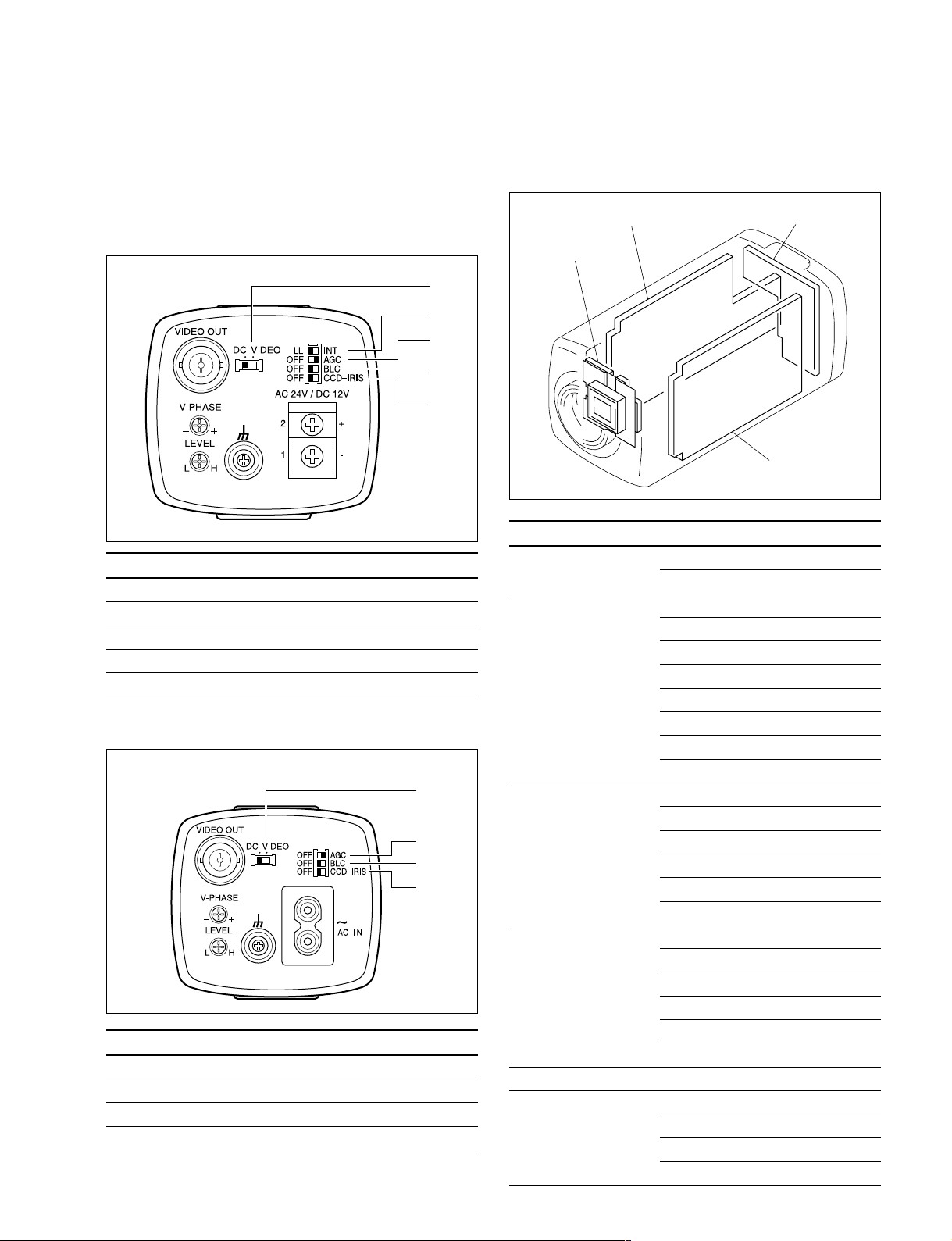
1-1. Factory Default Setting of Switch
For SSC-DC193/DC193P/DC393/DC393P/M183/
M183CE/M383/M383CE
1
2
3
4
5
No. Description Factory default setting
1 Auto iris lens selection switch DC
2 Sync switch LL
3 AGC ON/OFF switch AGC
4 BLC ON/OFF switch OFF
5 CCD-IRIS ON/OFF switch OFF
For SSC-DC198P/DC398P/M188CE/M388CE
1
2
3
4
No. Description Factory default setting
1 Auto iris lens selection switch DC
2 AGC ON/OFF switch AGC
3 BLC ON/OFF switch OFF
4 CCD-IRIS ON/OFF switch OFF
SSC-M183/M183CE/M188CE/M383/M383CE/M388CE
SSC-DC193/DC193P/DC198P/DC393/DC393P/DC398P
1-2. Board Location
AC-230/24 board
F2001 board
Board name Use model
AC-230board SSC-M188CE/M388CE
SSC-DC198P/DC398P
AC-24 board SSC-M183
SSC-M183CE
SSC-M383
SSC-M383CE
SSC-DC193
SSC-DC193P
SSC-DC393
SSC-DC393P
PB-2001 board SSC-M183
SSC-M183CE
SSC-M188CE
SSC-M383
SSC-M383CE
SSC-M388CE
PC-2001 board SSC-DC193
SSC-DC193P
SSC-DC198P
SSC-DC393
SSC-DC393P
SSC-DC398P
F2001 Board Common use
R-2001 Board SSC-M183/M183CE/M383/M383CE
SSC-M188CE/M388CE
SSC-DC193/DC193P/DC393/DC393P
SSC-DC198P/DC398P
R-2001 board
PB-2001/PC-2001 board
1-1
1-3. Installation/Removal of Cabinet
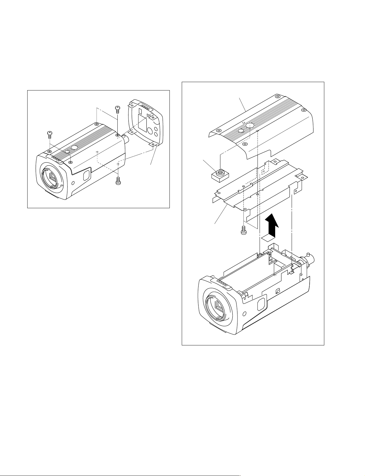
1-3-1. Top Cover
1. Remove the six screws, then remove the rear panel.
B 2x5
B 2x5
Rear panel
B 2x5
2. Remove the top cover in the direction indicated by the
arrow.
3. Remove the two screws, then remove the top chassis
and camera screw.
Top cover
Camera
screw
Top chassis
PTP 2x5
4. Attach the top cover in the reverse order of steps 1 to
3.
1-2
SSC-M183/M183CE/M188CE/M383/M383CE/M388CE
SSC-DC193/DC193P/DC198P/DC393/DC393P/DC398P
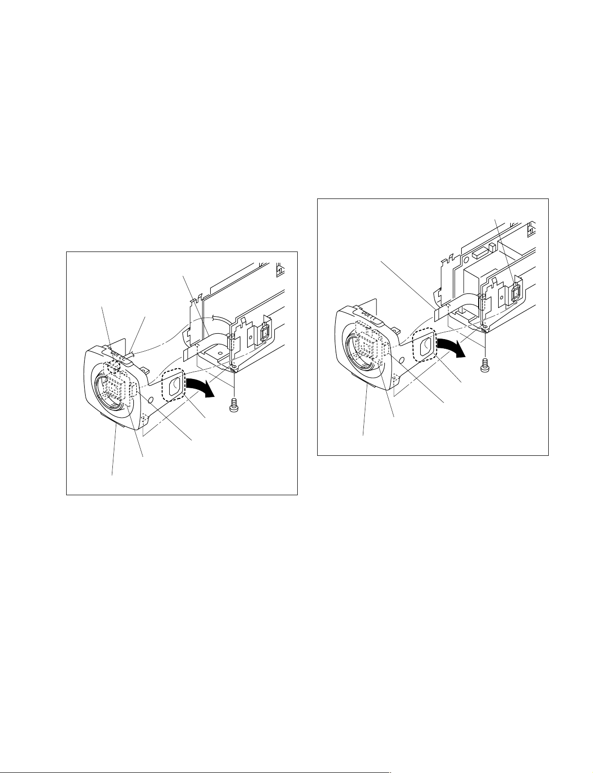
1-3-2. Front Cover Assembly
B 2x5
Lens connector
Flexible flat cable
Front cover assembly
Portion A
F-2001 board
CN401
For SSC-M183/M183CE/M188CE/M383/M383CE/
M388CE
1. Remove the top cover. (Refer to Section 1-3-1.)
2. Remove the two screws.
3. Move portion A of the front cover assembly in the
direction indicated by the arrow, then remove the front
cover assembly.
4. Disconnect one flexible flat cable from the connector
(CN401) on the F-2001 board.
5. Remove one solder from the F-2001 board, then
disconnect one lead wire.
Flexible flat cable
Solder
Lead wire
For SSC-DC193/DC193P/DC198P/DC393/DC393P/
DC398P
1. Remove the top cover. (Refer to Section 1-3-1.)
2. Remove the two screws.
3. Move portion A of the front cover assembly in the
direction indicated by the arrow, then remove the front
cover assembly.
4. Disconnect one flexible flat cable from the connector
(CN401) on the F-2001 board.
6. Attach the front cover assembly in the reverse order of
F-2001 board
Front cover assembly
steps 1 to 5.
Portion A
CN401
B 2x5
5. Attach the front cover assembly in the reverse order of
steps 1 to 4.
1-3-3. Bottom Cover
n
Be sure to attach the plate reinforcement in place.
For details on the installation of the plate reinforcement,
refer to Section 1-6.
For SSC-M183/M183CE/M383/M383CE/DC193/
DC193P/DC393/DC393P
1. Remove the top cover. (Refer to Section 1-3-1.)
2. Remove the front cover assembly. (Refer to Section 13-2.)
3. Remove the two screws (B 2x5), then remove the rear
chassis assembly.
SSC-M183/M183CE/M188CE/M383/M383CE/M388CE
SSC-DC193/DC193P/DC198P/DC393/DC393P/DC398P
1-3
4. Remove one screw (B 2x5), then remove the PB2001/PC-2001 board from the bottom chassis. (Refer
to Section 1-3-3.)
5. Remove one screw (B 2x5), then remove the plate
reinforcement. (Refer to Section 1-6.)
6. Remove one screw (B 2x5), then remove the AC-24
board from the bottom chassis. (Refer to Section 1-4-
3.)
7. Remove the two screws (PTP 2x5), then remove the
bottom chassis and camera screw from the bottom
cover.
B 2x5
Rear chassis assembly
B 2x5
For SSC-M188CE/M388CE/DC198P/DC398P
1. Remove the top cover. (Refer to Section 1-3-1.)
2. Remove the front cover assembly. (Refer to Section 13-2.)
3. Remove the two screws, then remove the rear chassis
assembly.
4. Remove one screw, then remove the PB-2001/PC2001 board from the bottom chassis. (Refer to Section
1-3-3.)
5. Remove one screw, then remove the AC-230 board
from the bottom chassis. (Refer to Section 1-4-3.)
6. Remove the two screws, then remove the bottom
chassis and camera screw from the bottom cover.
AC-230 board
B 2x5
Rear chassis assembly
AC-24 board
PB-2001
/PC-2001 board
Bottom
chassis
B 2x5
PTP 2x5
B 2x5
Plate
reinforcement
Camera screw
B 2x5
Bottom
chassis
B 2x5
PTP 2x5
B 2x5
B 2x5
PB-2001/
PC-2001 board
Camera screw
Bottom cover
n
Before attaching the rear chassis assembly, securely attach
the AC-24 board.
8. Attach the bottom cover in the reverse order of steps 1
to 7.
1-4
Bottom cover
n
Before attaching the rear chassis assembly, securely attach
the AC-230 board.
7. Attach the bottom cover in the reverse order of steps 1
to 6.
SSC-M183/M183CE/M188CE/M383/M383CE/M388CE
SSC-DC193/DC193P/DC198P/DC393/DC393P/DC398P
1-4. Installation/Removal of Board
1-4-1. R-2001 Board
For SSC-M183/M183CE/M383/M383CE/DC193/
DC193P/DC393/DC393P
1. Remove the top cover. (Refer to Section 1-3-1.)
2. Remove the front cover assembly. (Refer to Section 13-2.)
3. Remove the rear chassis assembly. (Refer to Section 13-3.)
4. Remove the PB-2001/PC-2001 board from the bottom
chassis. (Refer to Section 1-3-3.)
5. Remove the AC-24 board from the bottom chassis.
(Refer to Section 1-3-3.)
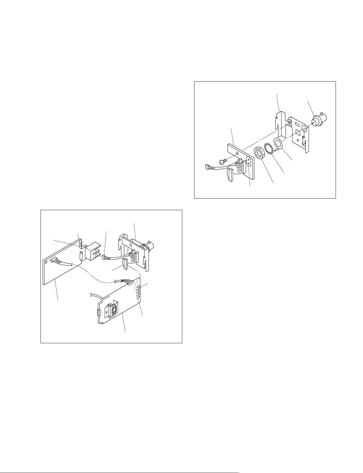
6. Remove the solder from the connector (CN203/204)
on the PB-2001/PC-2001 board, then disconnect one
harness.
7. Remove the solder from the connector (CN103) on the
AC-24 board, then disconnect one harness.
Rear chassis assembly
Solder
CN103
Harness
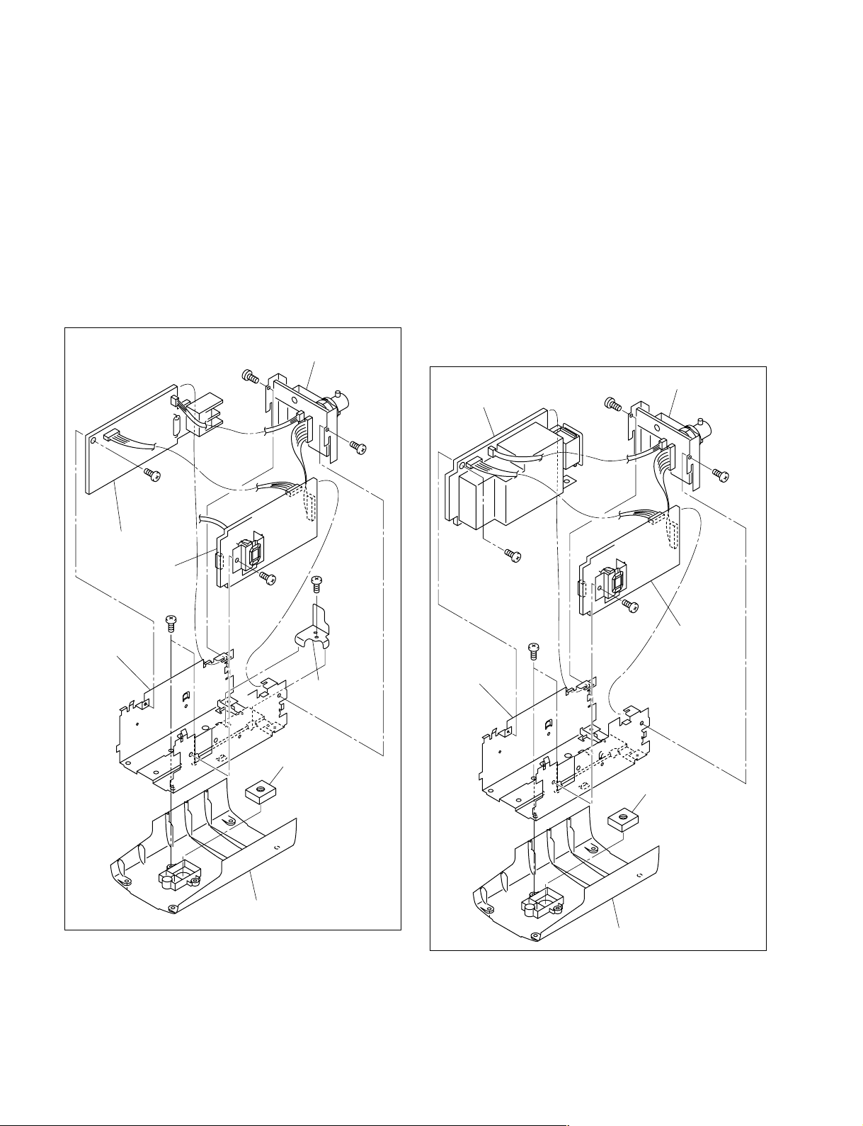
8. Remove one screw and two solders, then remove the
R-2001 board.
9. Remove the nut, then remove the toothed washer, earth
lug and BNC connector from the rear chassis.
Rear chassis
BNC connector
R-2001 board
B 2x5
Earth lug
Toothed washer
Two solders
Nut
10. Attach the R-2001 board in the reverse order of steps 1
to 9.
AC-24 board
Harness
Solder
CN203 (PB-2001 board)
CN204 (PC-2001 board)
PB-2001/PC-2001 board
SSC-M183/M183CE/M188CE/M383/M383CE/M388CE
SSC-DC193/DC193P/DC198P/DC393/DC393P/DC398P
1-5
For SSC-M188CE/M388CE/DC198P/DC398P
1. Remove the top cover. (Refer to Section 1-3-1.)
2. Remove the front cover assembly. (Refer to Section 13-2.)
3. Remove the rear chassis assembly. (Refer to Section 13-3.)
4. Remove the PB-2001/PC-2001 board from the bottom
chassis. (Refer to Section 1-3-3.)
5. Remove the AC-230 board from the bottom chassis.
(Refer to Section 1-3-3.)
6. Remove the solder from the connector (CN203/204)
on the PB-2001/PC-2001 board, then disconnect one
harness.
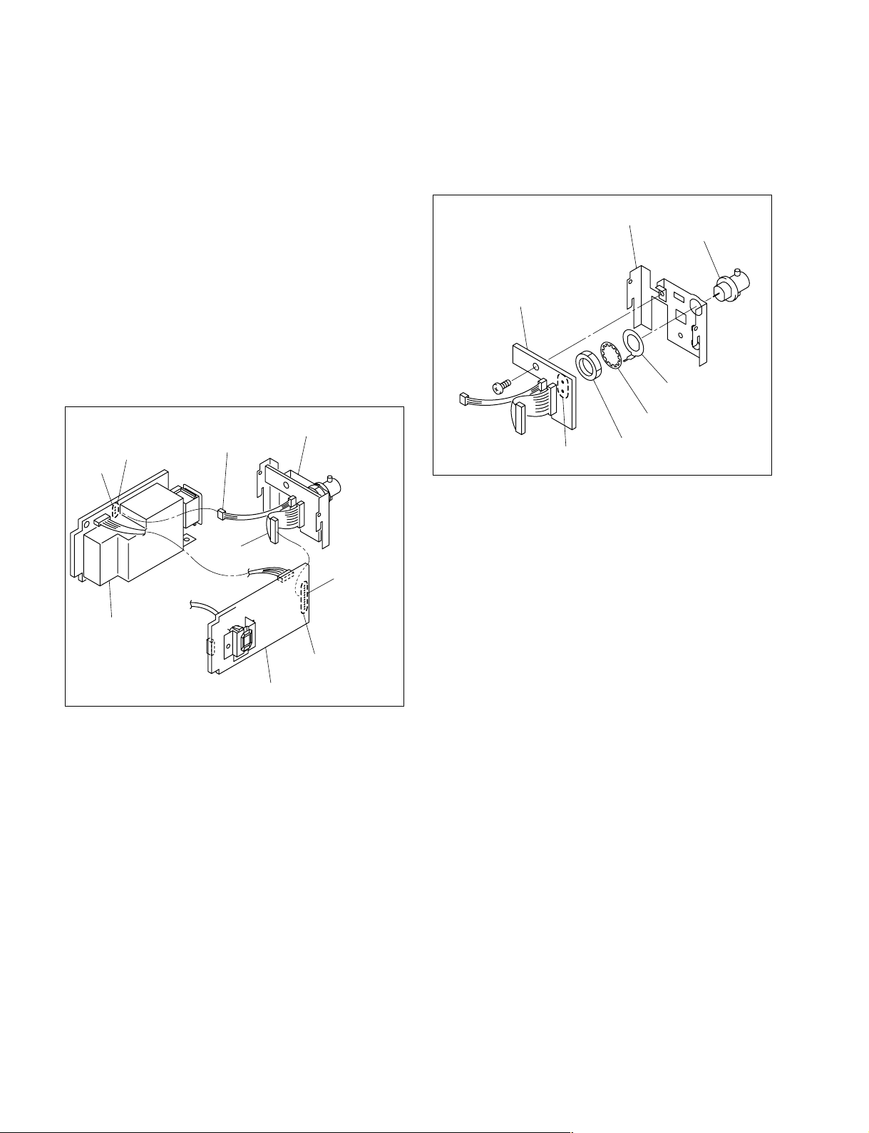
7. Remove the solder from the connector (CN603) on the
AC-230 board, then disconnect one harness.
8. Remove one screw and two solders, then remove the
R-2001 board.
9. Remove the nut, then remove the toothed washer, earth
lug and BNC connector from the rear chassis.
Rear chassis
BNC connector
R-2001 board
B 2x5
Earth lug
CN603
Solder
AC-230 board
Rear chassis assembly
Harness
Harness
CN203 (PB-2001 board)
CN204 (PC-2001 board)
PB-2001/PC-2001 board
Solder
Toothed washer
Two solders
Nut
10. Attach the R-2001 board in the reverse order of steps 1
to 9.
1-6
SSC-M183/M183CE/M188CE/M383/M383CE/M388CE
SSC-DC193/DC193P/DC198P/DC393/DC393P/DC398P
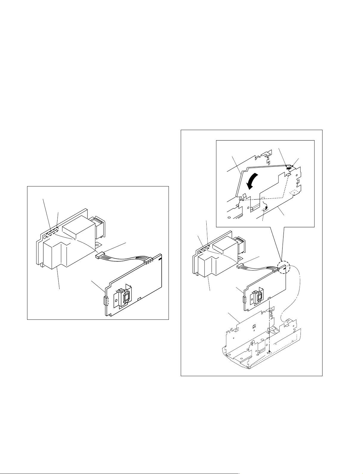
1-4-2. PB-2001/PC-2001 Board
For SSC-M183/M183CE/M383/M383CE/DC193/
DC193P/DC393/DC393P
Removal
1. Remove the top cover. (Refer to Section 1-3-1.)
2. Remove the front cover assembly. (Refer to Section 13-2.)
3. Remove the rear chassis assembly. (Refer to Section 13-3.)
4. Remove the plate reinforcement. (Refer to Section 1-
6.)
5. Remove the PB-2001/PC-2001 board from the bottom
chassis. (Refer to Section 1-3-3.)
6. Remove the AC-24 board from the bottom chassis.
(Refer to Section 1-3-3.)
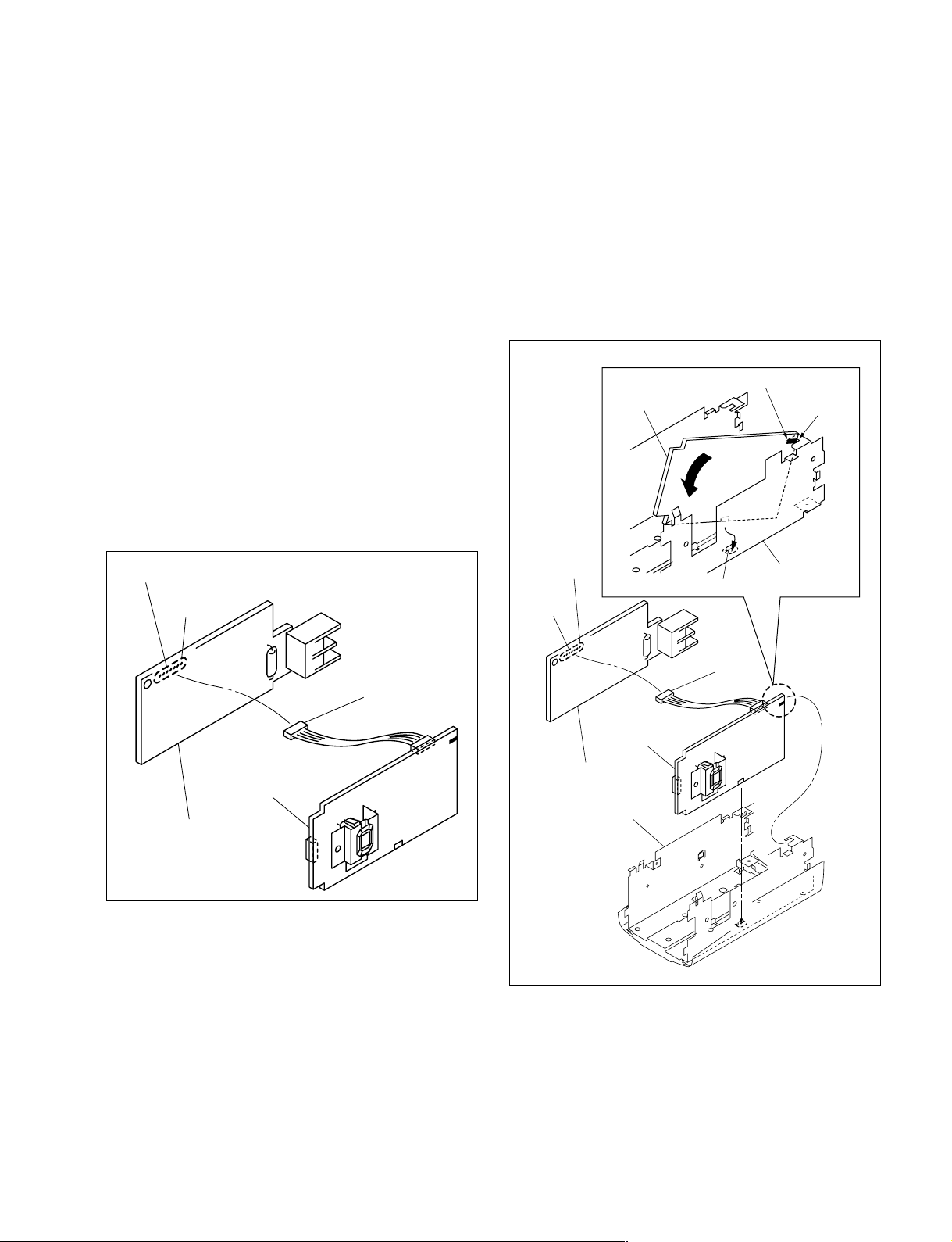
7. Remove the solder from the connector (CN102) on the
AC-24 board, then remove the PB-2001/PC-2001
board.
Installation
1. Attach the AC-24 board in the reverse order of steps 6
and 7 of the Removal.
2. Insert the marking section of the PB-2001/PC-2001
board into the groove of the bottom chassis, then
attach in the direction indicated by the arrow.
3. Attach the PB-2001/PC-2001 board so that it is placed
outside of the claw of the bottom chassis.
4. Attach the PB-2001/PC-2001 board in the reverse
order of steps 1 to 3.
PB-2001
/PC-2001 board
Marking
Groove
Solder
CN102
AC-24 board
PB-2001
/PC-2001 board
Harness
CN102
Solder
AC-24 board
Bottom chassis
Claw
Bottom chassis
Harness
PB-2001
/PC-2001 board
SSC-M183/M183CE/M188CE/M383/M383CE/M388CE
SSC-DC193/DC193P/DC198P/DC393/DC393P/DC398P
1-7
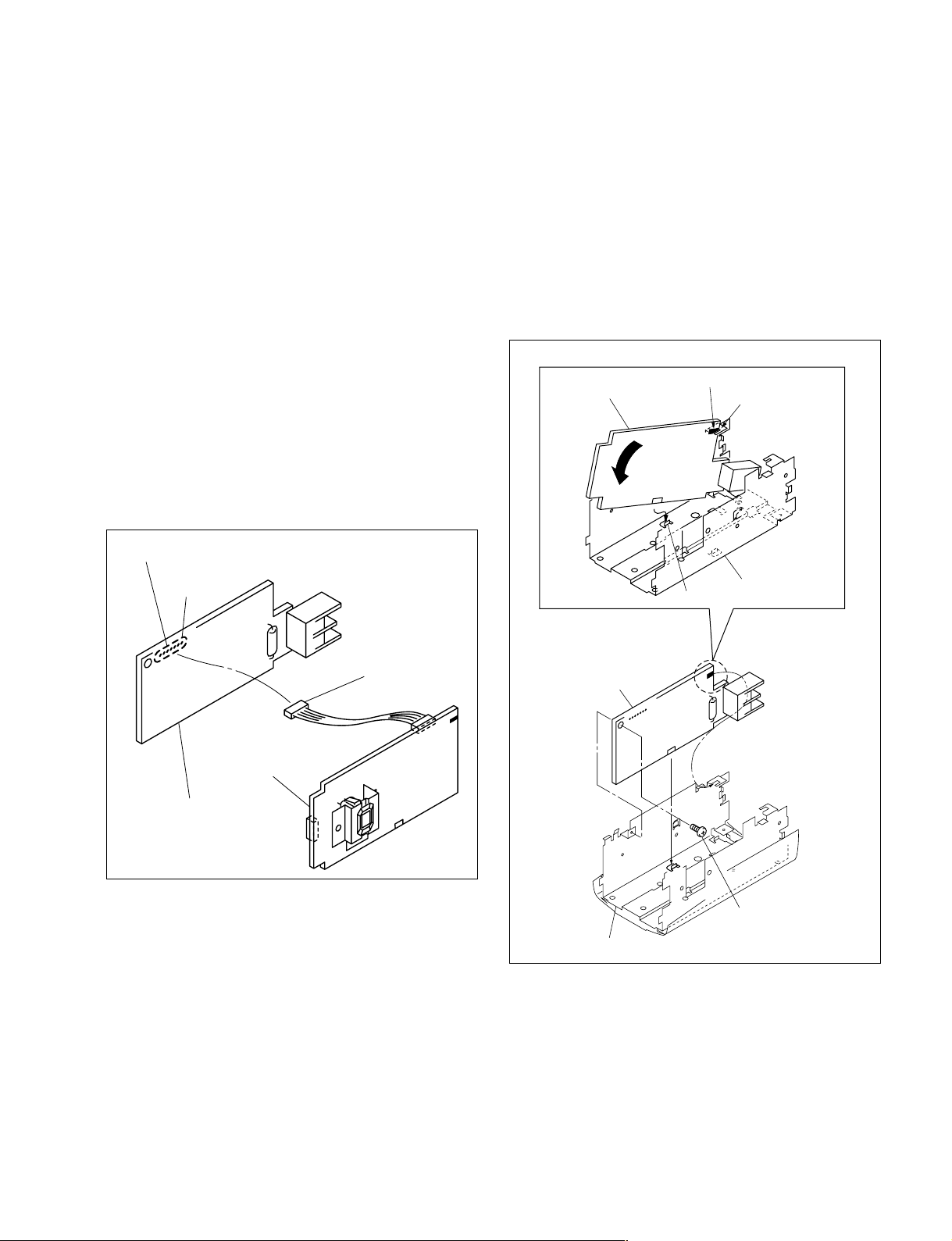
For SSC-M188CE/M388CE/DC198P/DC398P
Removal
1. Remove the top cover. (Refer to Section 1-3-1.)
2. Remove the front cover assembly. (Refer to Section 13-2.)
3. Remove the rear chassis assembly. (Refer to Section 13-3.)
4. Remove the plate reinforcement. (Refer to Section 1-
6.)
5. Remove the PB-2001/PC-2001 board from the bottom
chassis. (Refer to Section 1-3-3.)
6. Remove the AC-230 board from the bottom chassis.
(Refer to Section 1-3-3.)
7. Remove the solder from the connector (CN602) on the
AC-230 board, then remove the PB-2001/PC-2001
board.
Solder
CN602
Harness
Installation
1. Attach the AC-230 board in the reverse order of steps
6 and 7 of the Removal.
2. Insert the marking section of the PB-2001/PC-2001
board into the groove of the bottom chassis, then
attach in the direction indicated by the arrow.
3. Attach the PB-2001/PC-2001 board so that it is placed
outside of the claw of the bottom chassis.
4. Attach the PB-2001/PC-2001 board in the reverse
order of steps 1 to 3.
PB-2001
/PC-2001 board
CN602
Solder
Marking
Groove
Bottom chassis
Claw
AC-230 board
PB-2001
/PC-2001 board
Harness
PB-2001
/PC-2001 board
AC-230 board
Bottom chassis
1-8
SSC-M183/M183CE/M188CE/M383/M383CE/M388CE
SSC-DC193/DC193P/DC198P/DC393/DC393P/DC398P
1-4-3. AC-24/230 Board
For SSC-M183/M183CE/M383/M383CE/DC193/
DC193P/DC393/DC393P
Removal
1. Remove the top cover. (Refer to Section 1-3-1.)
2. Remove the front cover assembly. (Refer to Section 13-2.)
3. Remove the rear chassis assembly. (Refer to Section 13-3.)
4. Remove the plate reinforcement. (Refer to Section 1-
6.)
5. Remove the PB-2001/PC-2001 board from the bottom
chassis. (Refer to Section 1-3-3.)
6. Remove the AC-24 board from the bottom chassis.
(Refer to Section 1-3-3.)
7. Remove the solder from the connector (CN102) on the
AC-24 board, then remove the AC-24 board.
Solder
Installation
1. Attach the AC-24 board in the reverse order of steps 5
and 6.
2. Insert the marking section of the AC-24 board into the
groove of the bottom chassis, then attach in the
direction indicated by the arrow.
3. Attach the AC-24 board so that it is placed outside of
the claw of the bottom chassis.
4. Attach the AC-24 board in the reverse order of steps 1
to 4.
AC-24 board
Marking
Groove
CN102
AC-24 board
PB-2001
/PC-2001 board
Harness
AC-24 board
Bottom chassis
Claw
Bottom chassis
B 2x5
SSC-M183/M183CE/M188CE/M383/M383CE/M388CE
SSC-DC193/DC193P/DC198P/DC393/DC393P/DC398P
1-9
 Loading...