

Sony SLV-SE100, SLV-SE200, SLV-SE250, SLV-SE300, SLV-SE400 Service manual
...
SLV-SE100/SE200/SE250/SE300/
SE400/SE450/SX100/SX250
RMT-V257/V257A/V257B/V257C/V287
SERVICE MANUAL
AEP Model
SLV-SE100A1/A2/K,SE200V1/V2,
SE250B/D/P,SE300D1/D2,
SE400K,SE450B/D/K/P,
SX100K,SX250D
UK Model
SLV-SE200G/I,SE300G
East European Model
Russian Model
SLV-SE100K,SE400K,
SE450K,SX100K
(Except UK Model)
(UK Model only)
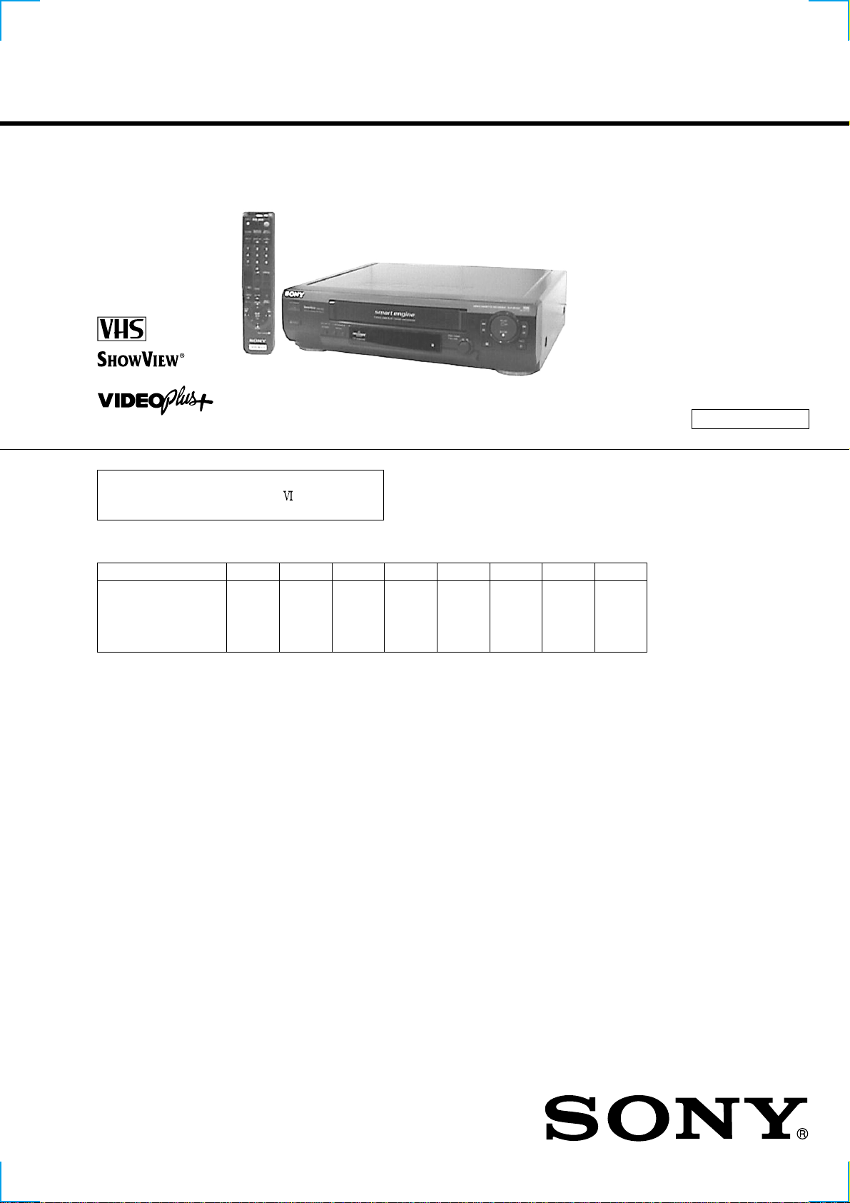
Photo : SL V -SE450D
RMT-V257B
Refer to the SERVICE MANUAL of VHS
MECHANICAL ADJUSTMENT
for
MECHANICAL ADJUSTMENTS. (9-921-647-11)
The abbreviations of SE100/SE200/SE250/SE300/SE400/SE450/SX100/SX250 contained in this service manual
are indicated when these models are common to all their corresponding models as given below.
Abbreviated models name
All models name
SLV-
SE100
SE100A1
SE100A2
SE100K
SE200
SE200G
SE200I
SE200V1
SE200V2
SE250
SE250B
SE250D
SE250P
SE300
SE300D1
SE300D2
SE300G
SE400
SE400K
SE450
SE450B
SE450D
SE450K
SE450P
SX100
SX100K
SX250
SX250D
SPECIFICATIONS
System
C
hannel coverage
SLV-SE100K,SE400K,SE450K,SX100K:
PAL (B/G, D/K)
VHF E2–E12, R1–R12
UHF E21–E69, R21–R69
CATV S1–S41, S01–S05
SLV-SE200G/I, SE300G:
PAL ( I)
VHF IA to IJ, SA10 to SA13 (SLV-SE200I only)
UHF B21 to B69
CATV S01 to S05, S1 to S20 (SLV-SE200I only)
HYPER S21 to S41 (SLV-SE200I only)
SLV-SE100A1/A2, SE200V1/V2, SE250D/P,
SE300D1/D2, SE450D/P, SX250D:
PAL ( B/G)
VHF E2 to E12
Canaux VHF italiens A to H
UHF E21 to E69
CATV S01 to S05, S1 to S20
HYPER S21 to S41
SLV-SE250B,SE450B:
SECAM (L):
VHF F2 to F10
UHF F21 to F69
CATV B to Q
HYPER S21 to S41
PAL (B/G):
VHF E2 to E12
Canaux VHF italiens A to H
UHF E21 to E69
CATV S01 to S05, S1 to S20
HYPER S21 to S41
RF output signal
UHF channels 21–69
Aerial out
75-ohm asymmetrical aerial socket
Tape speed
SP: PAL/MESECAM 23.39 mm/s
NTSC 33.35 mm/s
(SLV-SE250B,SE450B only)
SECAM 23,39 mm/s (recording/playback)
M
ESECAM 23,39 mm/s (playback only)
LP*: PAL/MESECAM 11.70 mm/s
(playback only, except: SLV-SE200G/I, SE300G)
(recording/playback: SLV-SE200G/I, SE300G)
NTSC 16.67 mm/s (playback only)
(SLV-SE450B only)
SECAM 11,70 mm/s (recording/playback)
M
ESECAM 11,70 mm/s (playback only)
EP*: NTSC 11.12 mm/s (playback only)
(SLV-SE200G/I, SE250D/P, SE300D1/D2/G,
Maximum recording/playback time
Fast-forward and rewind time
SE450B/D/P, SX250D)
10 hrs. in LP mode (with E300 tape)
Approx. 3 min. (with E180 tape)
S MECHANISM
— Continued on next page —
VIDEO CASSETTE RECORDER

Inputs and outputs
LINE-1 (TV)
i
21-pin
Video input: pin 20
Audio input: pins 2 and 6
Video output: pin 19
Audio output: pins 1 and 3
SLV-SE250B/D/P, SE450B/D/P, SX250D:
DECODER/
SLV-SE300D1/D2:
DECODER/
SLV-SE300D1/D2/G:
LINE-2 IN
SLV-SE300G:
LINE-3 IN
tLINE-2 IN
21-pin
Video input: pin 20
Audio input: pins 2 and 6
tLINE-3 IN
21-pin
Video input: pin 20
Audio input: pins 2 and 6
VIDEO IN, phono jack (1)
Input signal: 1 Vp-p, 75 ohms, unbalanced, sync
negative
AUDIO IN, phono jack (1)
Input level: 327 mVrms
Input impedance: more than 47 kilohms
21-pin
Video input: pin 20
Audio input: pins 2 and 6
General
Power requirements
220 – 240 V AC, 50 Hz
Power consumption
18 W
Operating temperature
5°C to 40°C
Storage temperature
–20°C to 60°C
Dimensions
prox. 355 × 96 × 285 mm (w/h/d)
Ap
(Approx. 14 × 3 /
including projecting parts and controls
Mass
Approx. 3.6 kg (Approx. 7 lb 15 oz.)
71
8
× 11 /4 inches)
Supplied accessories
Remote commander (1)
R6 (size AA) batteries (2)
Aerial cable (1)
Design and specifications are subject to change without
notice.
SAFETY-RELATED COMPONENT WARNING!!
COMPONENTS IDENTIFIED BY MARK 0 OR DOTTED LINE WITH
MARK 0 ON THE SCHEMATIC DIAGRAMS AND IN THE PARTS
LIST ARE CRITICAL TO SAFE OPERATION. REPLACE THESE
COMPONENTS WITH SONY PARTS WHOSE PART NUMBERS
APPEAR AS SHOWN IN THIS MANUAL OR IN SUPPLEMENTS
PUBLISHED BY SONY.
SAFETY CHECK-OUT
After correcting the original service problem, perform the following
safety checks before releasing the set to the customer.
1. Check the area of your repair for unsoldered or poorly-soldered
connections. Check the entire board surface for solder splashes
and bridges.
2. Check the interboard wiring to ensure that no wires are
"pinched" or contact high-wattage resistors.
3. Look for unauthorized replacement parts, particularly
transistors, that were installed during a previous repair . Point
them out to the customer and recommend their replacement.
4. Look for parts which, through functioning, show obvious signs
of deterioration. Point them out to the customer and
recommend their replacement.
5. Check the B+ voltage to see it is at the values specified.
6. Flexible Circuit Board Repairing
• Keep the temperature of the soldering iron around 270˚C
during repairing.
• Do not touch the soldering iron on the same conductor of the
circuit board (within 3 times).
• Be careful not to apply force on the conductor when soldering
or unsoldering.
— 2 —

TABLE OF CONTENTS
SERVICE NOTE
1. ERROR CODE INDICATION···········································4
1 GENERAL
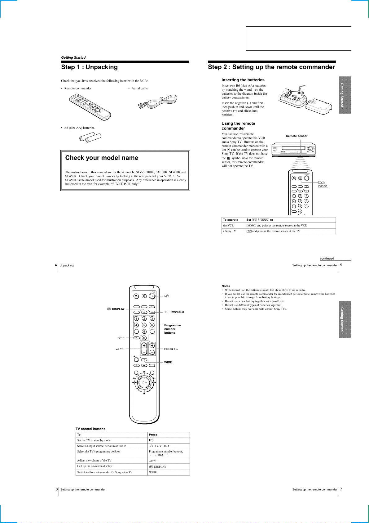
Getting Started···········································································1-1
Step 1 : Unpacking ································································1-1
Step 2 : Setting up the remote commander ····························1-1
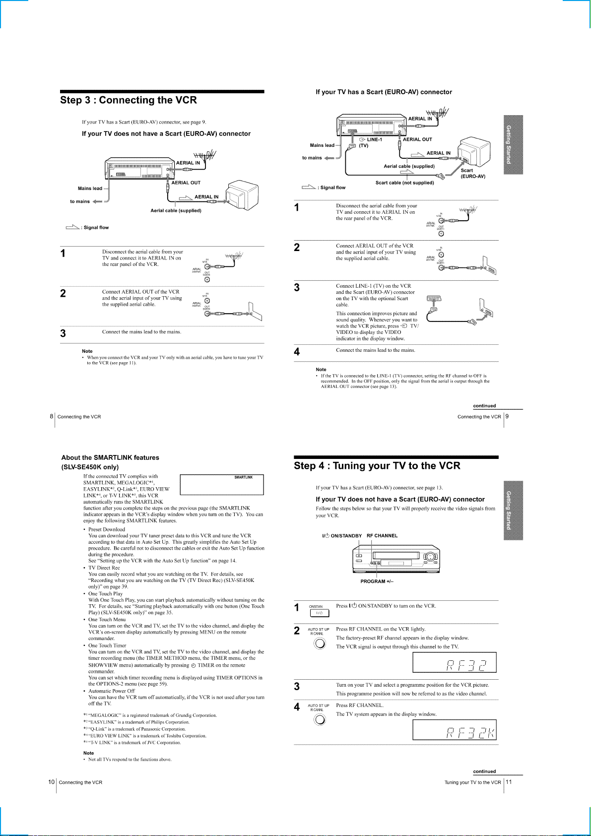
Step 3 : Connecting the VCR·················································1-2
Step 4 : Tuning your TV to the VCR ·····································1-2
Step 5 : Setting up the VCR with the Auto Set Up function··1-3
Step 6 : Setting the clock ·······················································1-4
Selecting a language ······························································ 1-5
Presetting channels ································································1-5
Changing/disabling programme positions ·····························1-6
Basic Operations········································································1-8
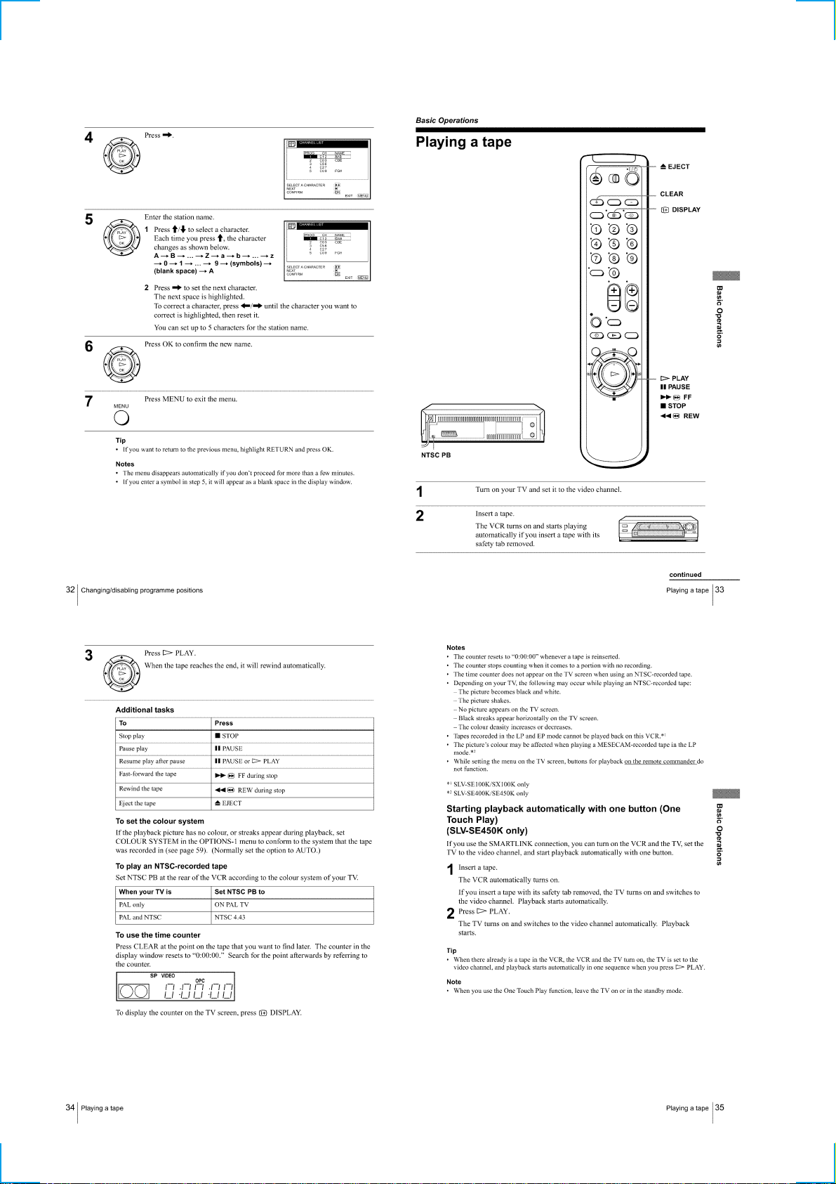
Playing a tape·········································································1-8
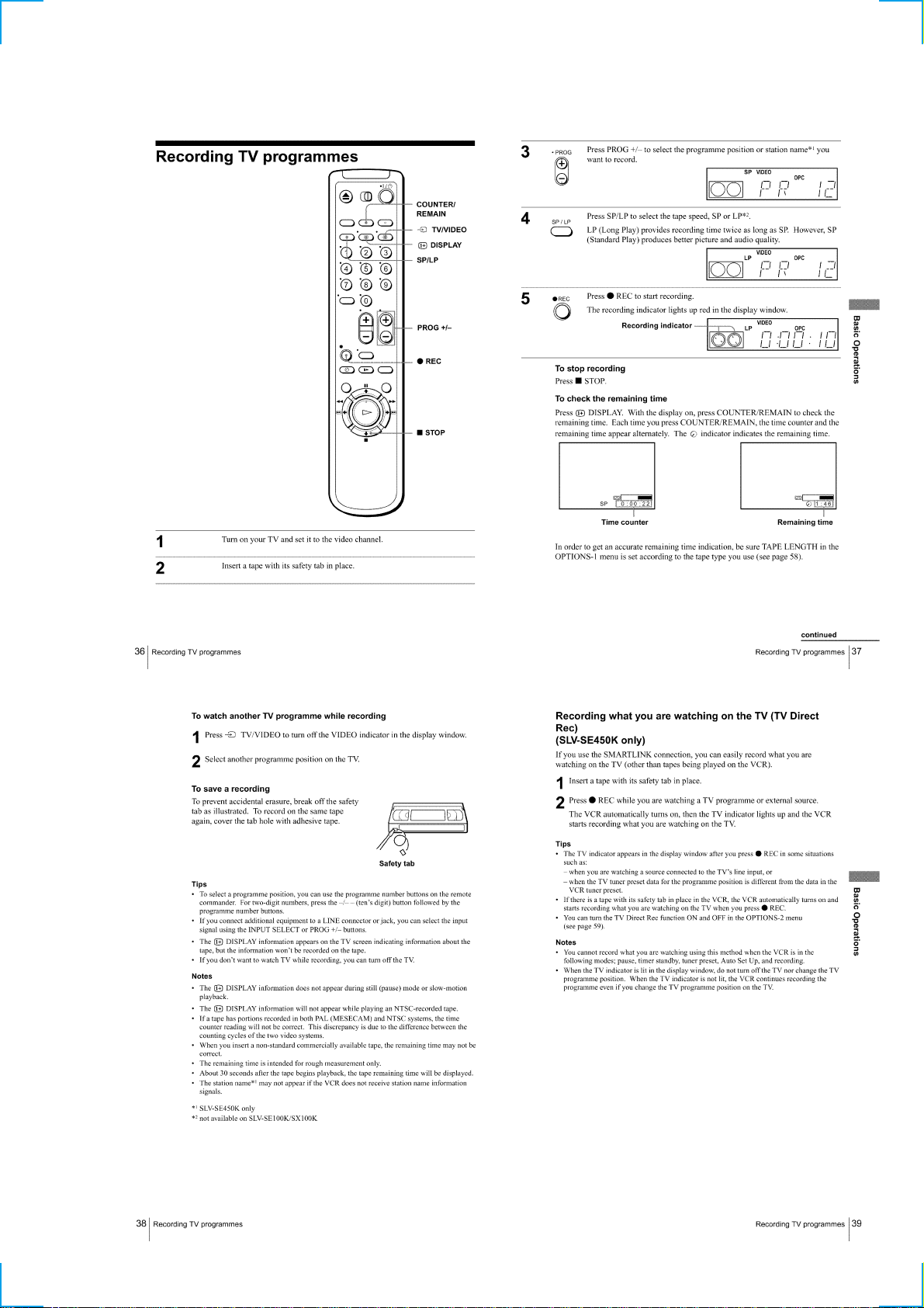
Recording TV programmes ···················································1-9
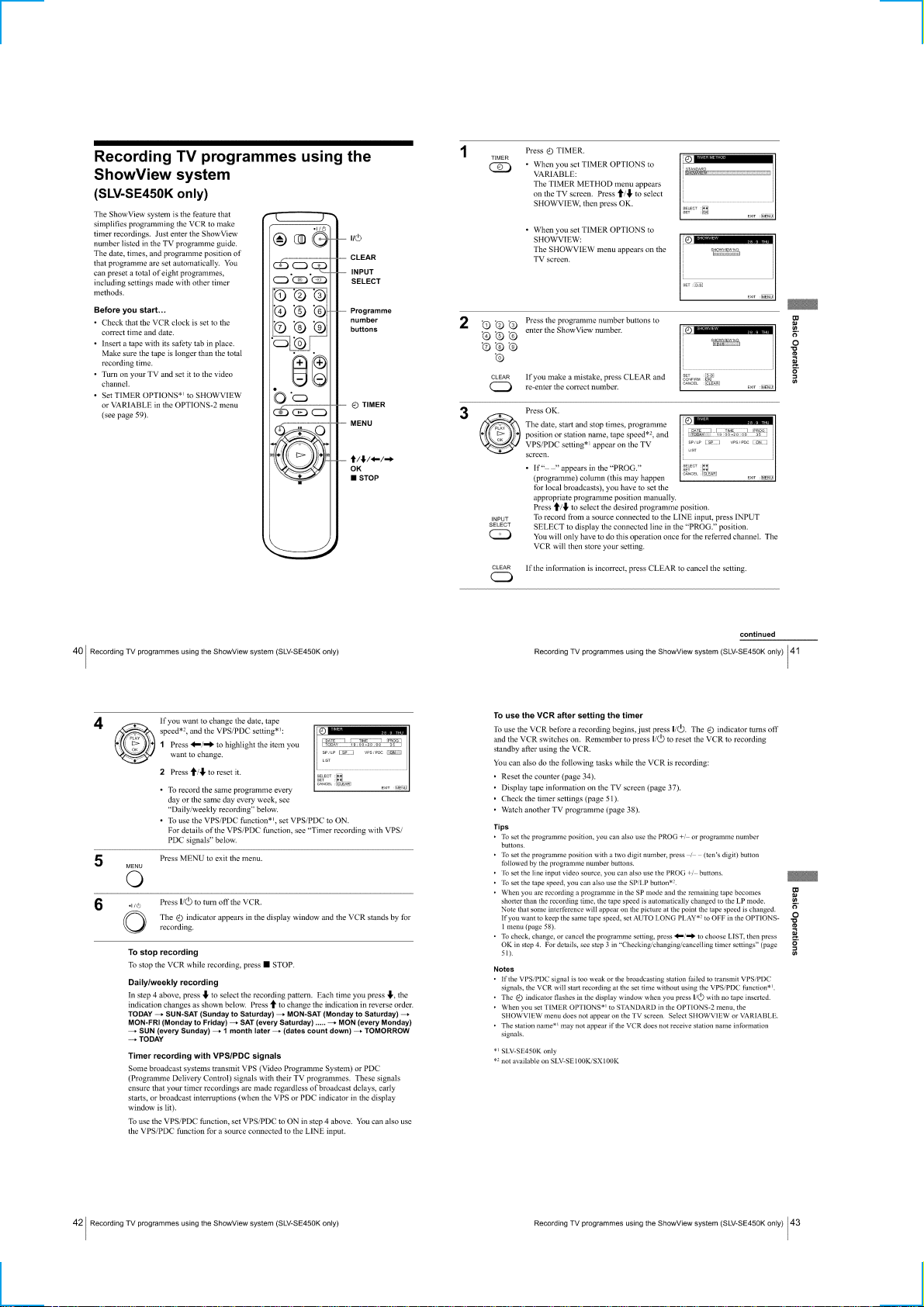
Recording TV programmes using the ShowView system ···1-10
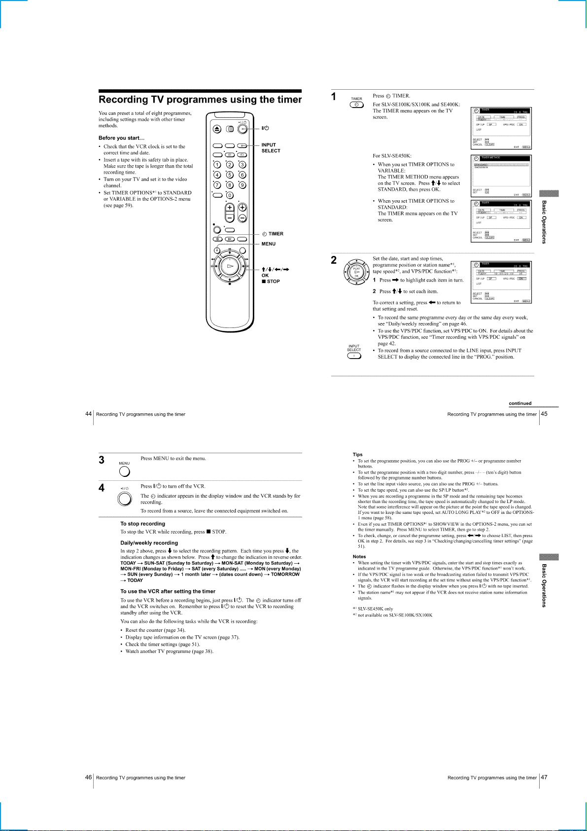
Recording TV programmes using the timer ························1-11
Additional Operations ·····························································1-12
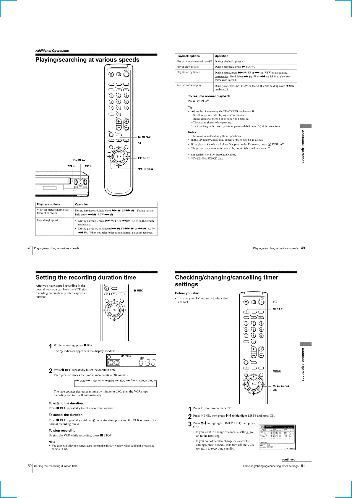
Playing/searching at various speeds ····································1-12
Setting the recording duration time ·····································1-12
Checking/changing/cancelling timer settings ······················1-12
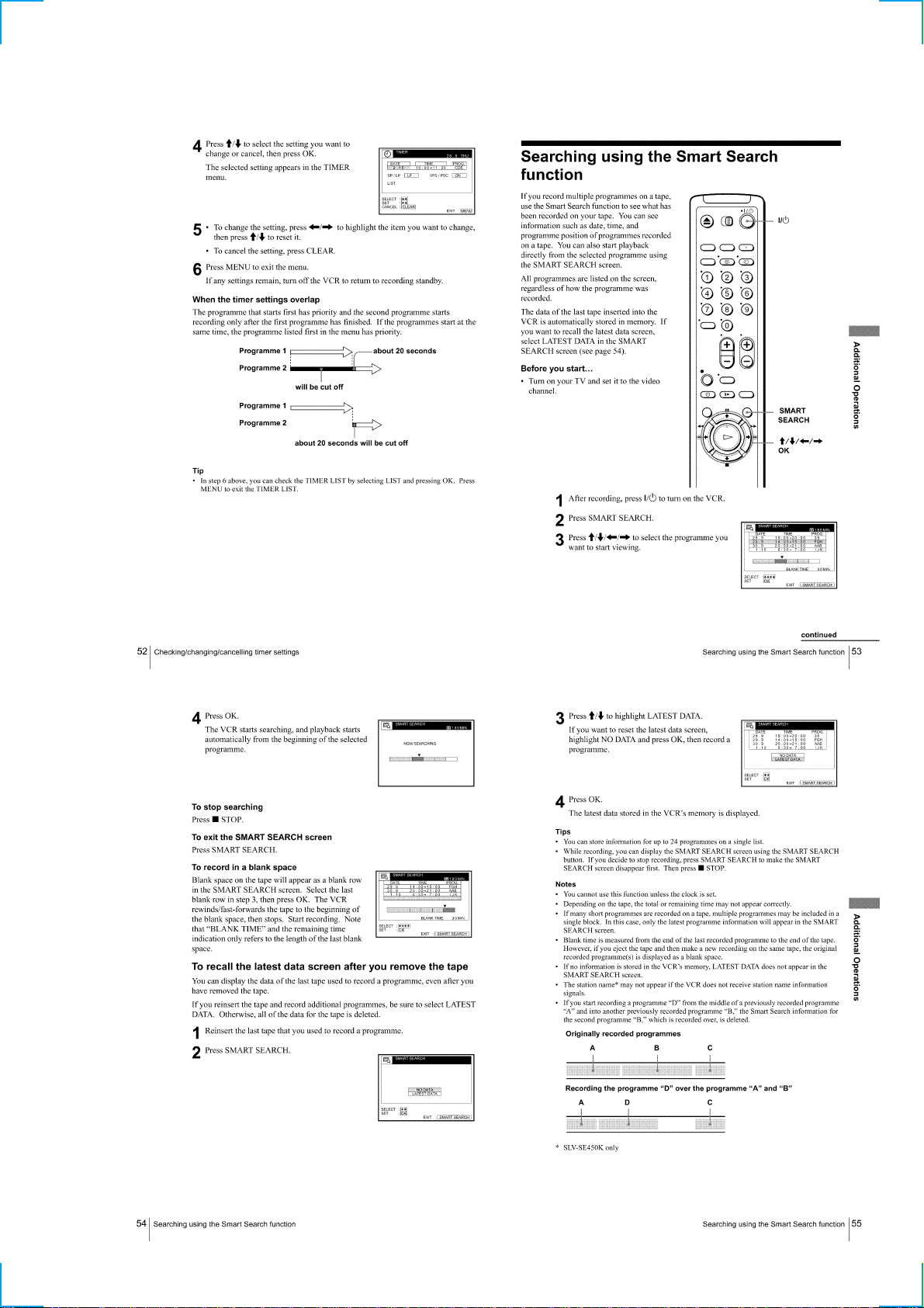
Searching using the Smart Search function ·························1-13
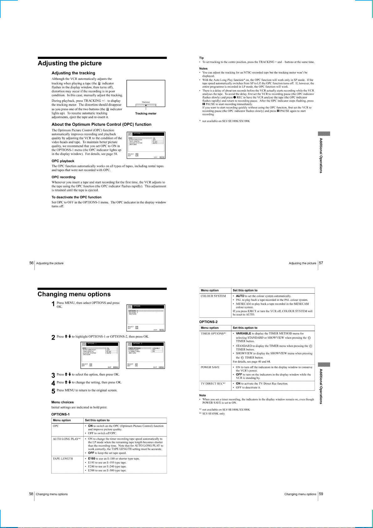
Adjusting the picture ···························································1-14
Changing menu options ·······················································1-14
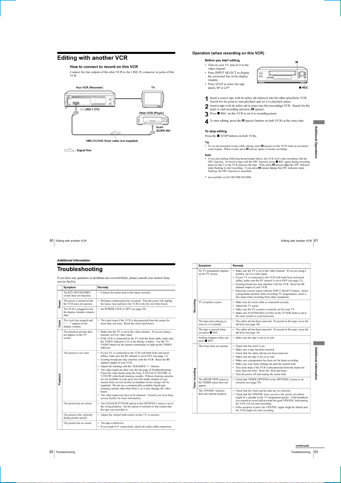
Editing with another VCR ··················································· 1-15
Additional Information ····························································1-15
Troubleshooting ···································································1-15
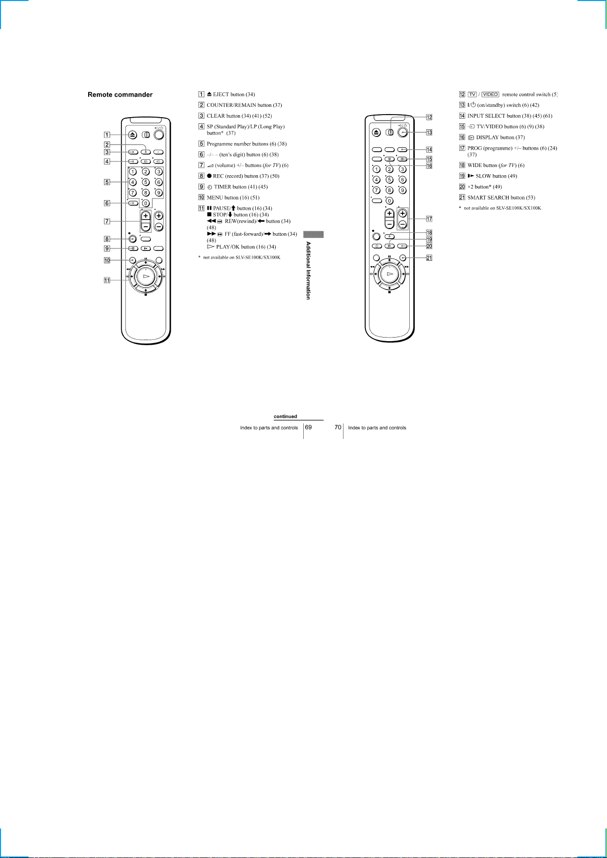
Index to parts and controls··················································· 1-16
2 DISASSEMBLY
2-1. CASE, FRONT PANEL BLOCK ASSEMBLY··············2-1
2-2. KK-22 BOARD (SE300, SE450B/D/P),
JK-179 BOARD (SE300) ················································2-1
2-3. REAR PANEL ·································································2-2
2-4. POWER BLOCK, MA-372 BOARD······························ 2-2
2-5. MECHANISM DECK·····················································2-3
2-6. INTERNAL VIEWS························································2-4
2-7. CIRCUIT BOARDS LOCATION···································2-5
3 BLOCK DIAGRAMS
3-1. OVERALL BLOCK DIAGRAM ····································3-1
3-2. VIDEO BLOCK DIAGRAM ··········································3-3
3-3. SERVO/SYSTEM CONTROL BLOCK DIAGRAM ·····3-5
3-4. AUDIO BLOCK DIAGRAM ··········································3-7
3-5. POWER BLOCK DIAGRAM·········································3-9
4 PRINTED WIRING BOARDS AND
SCHEMATIC DIAGRAMS
4-1. FRAME SCHEMATIC DIAGRAM································4-3
4-2. PRINTED WIRING BOARDS AND
SCHEMATIC DIAGRAMS ············································4-5
• MA-372 (VIDEO, AUDIO, SERVO/SYSTEM
CONTROL, TUNER, POWER SUPPLY)
PRINTED WIRING BOARD ·························4-5
• MA-372 (1/10)(REC/PB HEAD AMP)
SCHEMA)TIC DIAGRAM ····························4-7
• MA-372 (2/10)(SECAM PROCESSOR)
SCHEMATIC DIAGRAM ······························4-9
• MA-372 (3/10)(VPD/PDC)
SCHEMATIC DIAGRAM ····························4-11
• MA-372 (4/10)(Y/C, AUDIO PROCESSOR)
SCHEMATIC DIAGRAM ····························4-13
• MA-372 (5/10)(SERVO/SYSTEM CONTROL)
SCHEMATIC DIAGRAM ····························4-15
• MA-372 (6/10)(USER CONTROL)
SCHEMATIC DIAGRAM ····························4-17
• MA-372 (7/10)(INPUT/OUTPUT)
SCHEMATIC DIAGRAM ····························4-19
• MA-372 (8/10)(C+ SWITCH)
SCHEMATIC DIAGRAM ····························4-21
• MA-372 (9/10)(TUNER)
SCHEMATIC DIAGRAM ····························4-23
• MA-372 (10/10)(POWER SUPPLY)
SCHEMATIC DIAGRAM ····························4-25
• JK-179 (LINE-2 IN)
PRINTED WIRING BOARD AND
SCHEMATIC DIAGRAM ····························4-27
• KK-22 (DIAL TIMER)
PRINTED WIRING BOARD AND
SCHEMATIC DIAGRAM ····························4-27
• POWER SUPPLY BLOCK
PRINTED WIRING BOARD ·······················4-28
• POWER SUPPLY BLOCK
SCHEMATIC DIAGRAM ····························4-29
5 INTERFACE, IC PIN FUNCTION
DESCRIPTION
5-1. SYSTEM CONTROL — VIDEO/RP BLOCK
INTERFACE (MA-372 BOARD IC162) ························5-1
5-2. SYSTEM CONTROL — SERVO PERIPHERAL
CIRCUIT INTERFACE (MA-372 BOARD IC162) ·······5-1
5-3. SYSTEM CONTROL — MECHANISM BLOCK
INTERFACE (MA-372 BOARD IC162) ························5-2
5-4. SYSTEM CONTROL — SYSTEM CONTROL
PERIPHERAL CIRCUIT INTERFACE
(MA-372 BOARD IC162)···············································5-2
5-5. SYSTEM CONTROL — AUDIO BLOCK INTERFACE
(MA-372 BOARD IC162)···············································5-2
5-6. SERVO/SYSTEM CONTROL MICROPROCESSOR
PIN FUNCTIONS (MA-372 BOARD IC162)················5-3
5-7. MODE CONTROL PIN FUNCTIONS
(MA-372 BOARD IC420)···············································5-5
6 ADJUSTMENTS
6-1. MECHANICAL ADJUSTMENTS ·································6-1
6-2. ELECTRICAL ADJUSTMENTS ···································6-1
2-1. PREPARATION BEFORE ADJUSTMENT···················6-1
2-1-1.Equipment Required ························································6-1
2-1-2.Equipment Connection ····················································6-1
2-1-3.Set-up of Adjustment······················································· 6-1
2-1-4.Alignment Tape ·······························································6-1
2-1-5.Input/Output Levels and Impedance ·······························6-2
2-1-6.Adjustment Sequence ······················································6-2
2-2. POWER SUPPLY CHECK ·············································6-2
2-2-1.Output Voltage Check (MA-372 Board) ·························6-2
2-3. SERVO SYSTEM CHECK ·············································6-3
2-3-1.RF Switching Position Adjustment (MA-372 Board) ·····6-3
2-4. AUDIO SYSTEM ADJUSTMENT·································6-3
2-4-1.Normal Audio System Adjustment ··································6-3
2-4-2.ACE Head Adjustment ····················································6-3
2-4-3.E-E Output Level Check ·················································6-3
2-4-4.Frequency Response Check············································· 6-3
2-5. ADJUSTING PARTS LOCATION DIAGRAM ·············6-4
7 REPAIR PARTS LIST
7-1. EXPLODED VIEWS ······················································7-1
7-1-1.FRONT PANEL AND UPPER CASE SECTION ··········7-1
7-1-2.CHASSIS SECTION·······················································7-2
7-1-3.MECHANISM DECK SECTION-1 ·······························7-3
7-1-4.MECHANISM DECK SECTION-2 ·······························7-4
7-1-5.MECHANISM DECK SECTION-3 ·······························7-5
7-2. ELECTRICAL PARTS LIST ··········································7-6
— 3 —
SERVICE NOTE
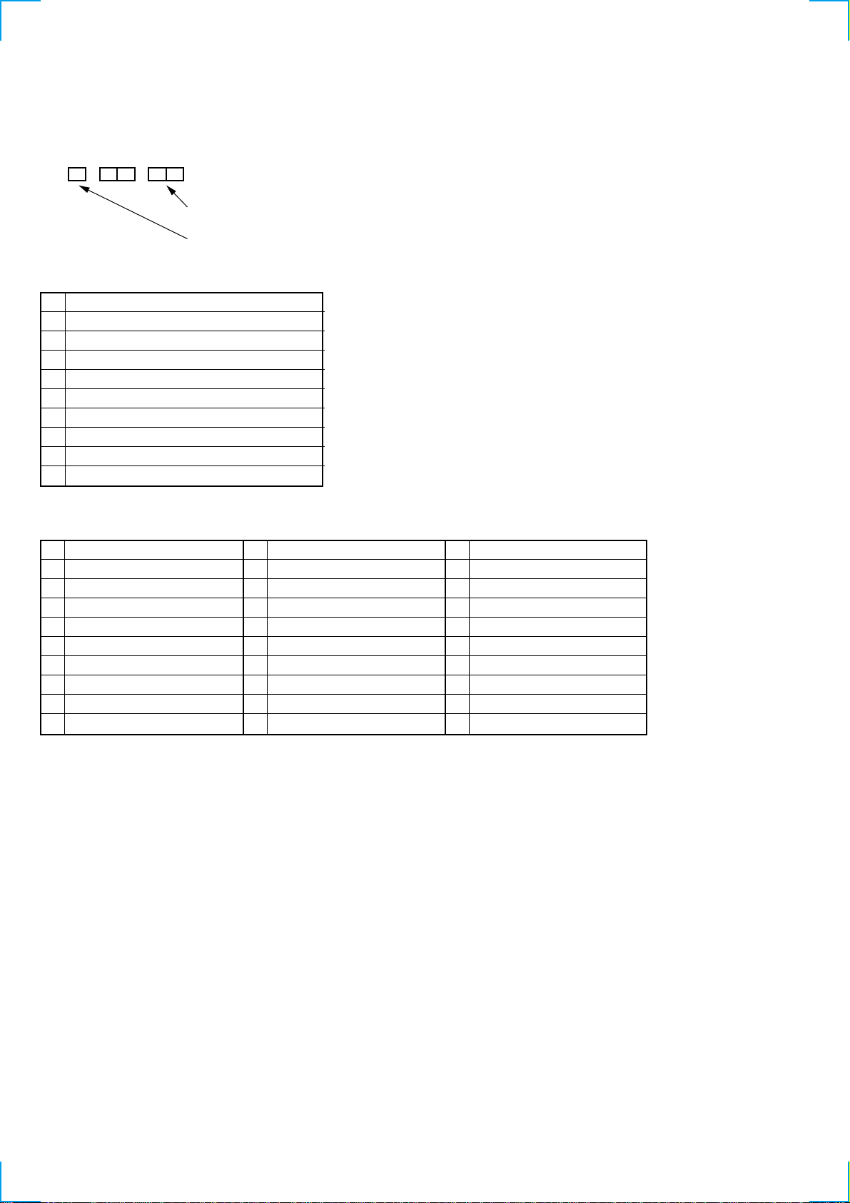
1. ERROR CODE INDICATION
• Error codes are indicated using the lower 5 digits in the fluorescent display tube.
“At this time, Colon “:” between character is not indicated.”
Mode code indication when the error has occurred.
Error code
ERROR CODE
0 No error
1 Cam encoder error Loading direction
2 Cam encoder error Unloading direction
3 T reel error
4 S reel error
5 Capstan error
6 Drum error
7 Error on initializing
8 Cassette loading error
9 Reserve
MODE CODE
0 Power-on eject 10 FWD x1 20 REW play
1 Power-on initial 11 FWD x2 21 Cas. loading
2 Power-off eject 12 CUE 22 Tape loading
3 Power-off stop 13 PB-pause 23 Power-off loading
4 FF 14 RVS-pause 24 Mecha. error (Power on)
5 REW 15 RVS x1 25 Power-on eject initial
6 REC 16 RVS x2 26 Power-off eject initial
7 REC- pause 17 REV 27 APC REC
8 Power-on stop 18 Power-off initial 28 Cas. loading
9 PB 19 Mecha. error (Power off) (No auto PB check)
— 4 —
SLV-SE100/SE200/SE250/SE300/SE400/SE450/SX100/SX250
SECTION 1
GENERAL
This section is extracted from instruction
manual. (SLV-SE100K/SX100K/SE400K/
SE450K model)(3-868-344-11)
1-1
1-2
1-3
1-4
1-5
1-6

1-7
1-8
1-9
1-10
1-11
1-12
1-13
1-14
1-15
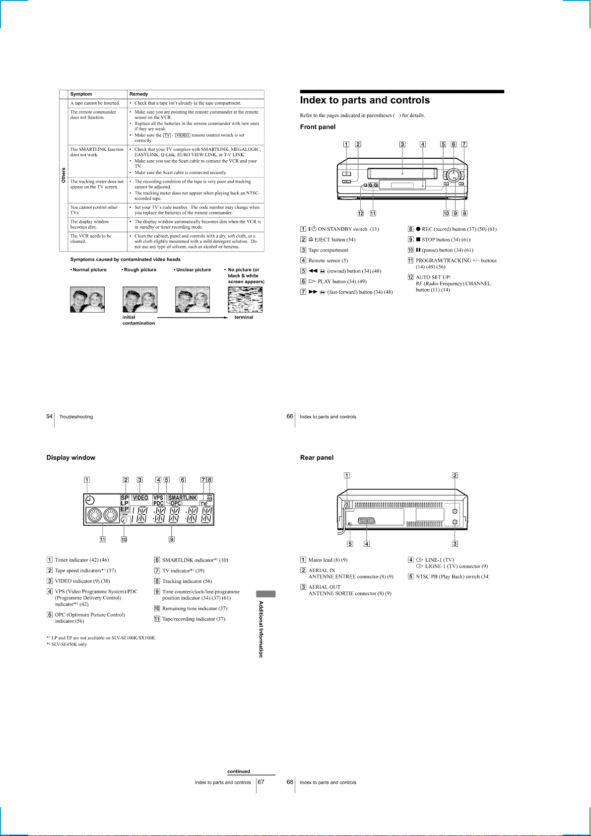
1-16
1-17

MEMO
1-18E
SLV-SE100/SE200/SE250/SE300/SE400/SE450/SX100/SX250
SECTION 2
DISASSEMBLY
NOTE: Follow the disassembly procedure in the numerical order given.
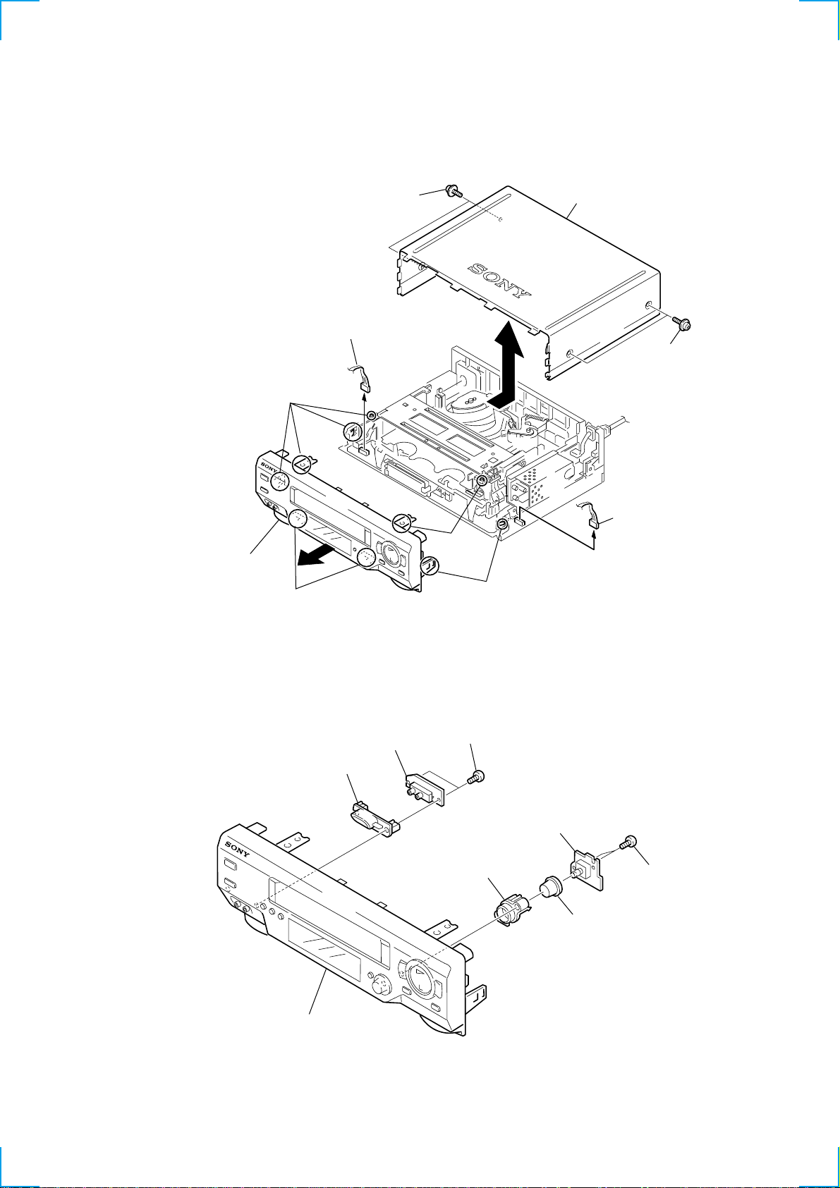
2-1. CASE, FRONT PANEL BLOCK ASSEMBLY
6 Panel block assembly
(Engaged by the hook.)
Hooks
Hooks
1 T apping screw
4 Connector
3 Upper case
2 Tapping screw
5 Connector
Hooks
Hooks
2-2. KK-22 BOARD (SE300, SE450B/D/P), JK-179 BOARD (SE300)
5 T wo screws
6 JK-179 board
7 Pin jack cover
Front panel assembly
(B2.6 × 8)
2 KK-22 board
4 Dial timer escutcheon
3 Dial timer knob
1 Two screws
(B2.6 × 8)
2-1
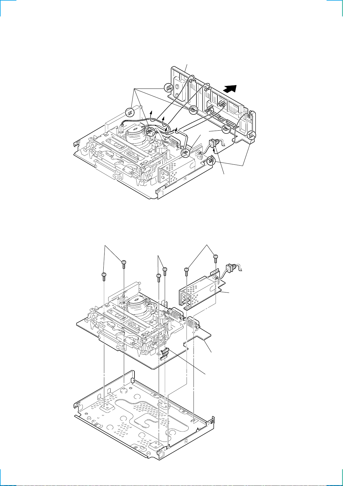
2-3. REAR PANEL
r
2 Rear panel
(Engaged by the hook.)
Hooks
Hooks
Hooks
1 POWER code stoppe
2-4. POWER BLOCK, MA-372 BOARD
4 T wo screws
(Sumitite (B3) +BV)
5 T wo screws
(Sumitite (B3) +BV)
2 T wo screws
3 Power block
6 MA-372 board with
mechanism deck
1 One connector
2-2
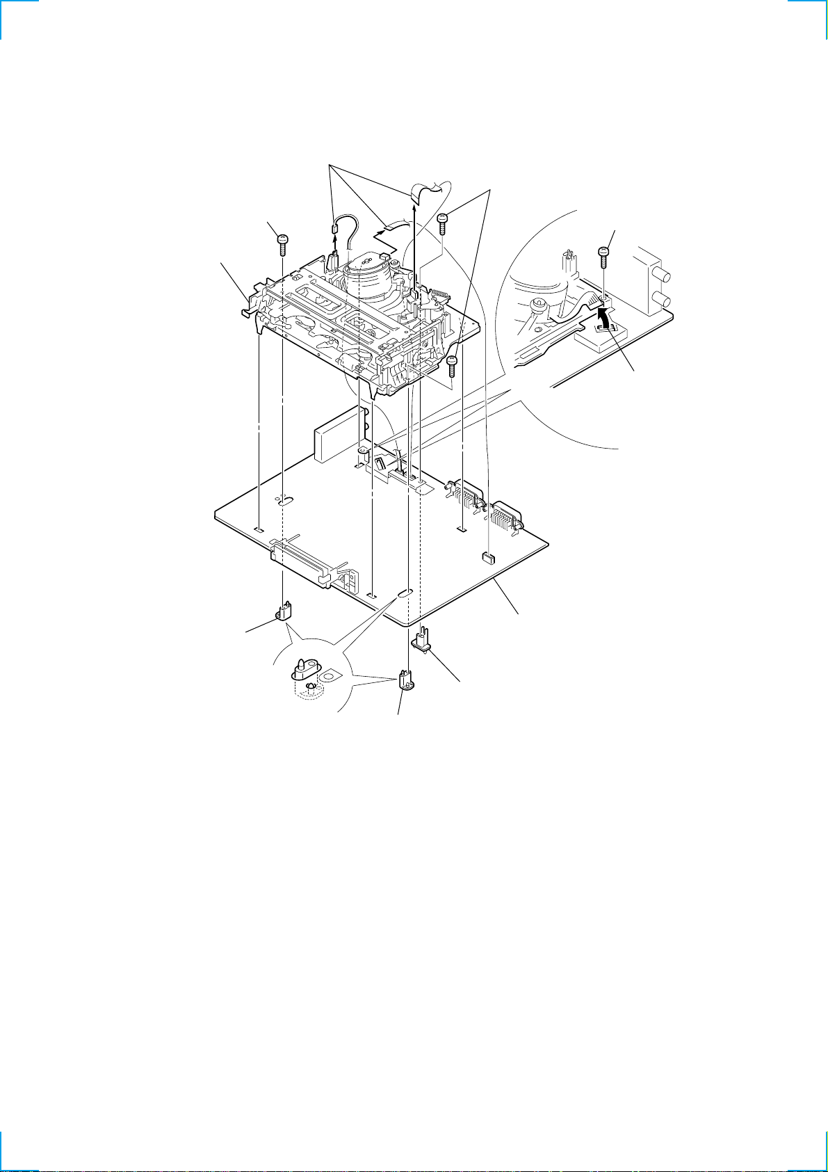
2-5. MECHANISM DECK
4 Screw
(BVTP 3 × 12)
0 Mechanism deck
3 Three connectors
6 T wo screws
(BVTP 3 × 12)
2 Screw
(BVTP 3 × 12)
1 Flexible board
5 MD base (R)
9 MA-372 board
8 MD base (M)
7 MD base (R)
2-3
 Loading...