

Sony SLV-789-HF Service manual
SLV-789HF/ 792HF/ 799HF
RTV servis Horvat
Kešinci, 31402 Semeljci
031-856-139
031-856-637
098-788-319
rtv-servis-horvat@os.tel.hr
Croatia
RMT-V267A
SERVICE MANUAL
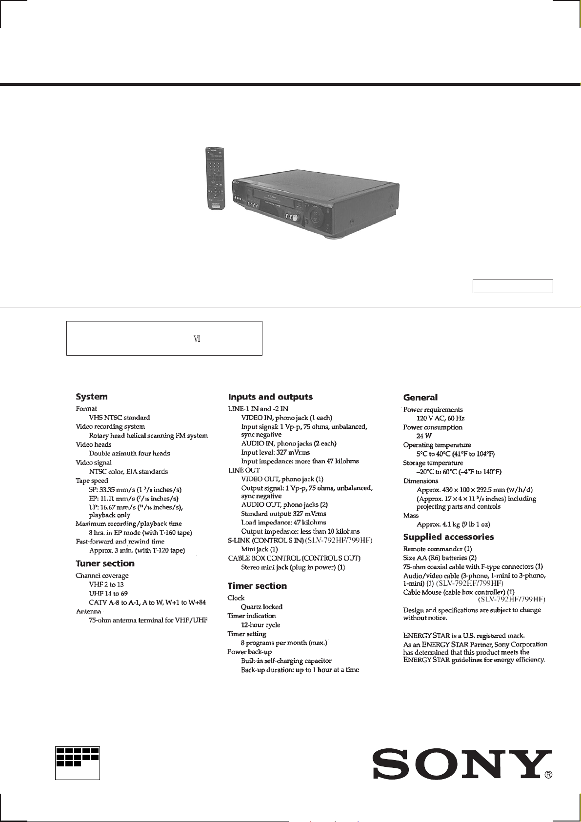
Photo: SLV-799HF
RMT-V267A
Refer to the SERVICE MANUAL of VHS
MECHANICAL ADJUSTMENT
MECHANICAL ADJUSTMENTS. (9-921-647-11)
for
SPECIFICATIONS
US Model
SLV-789HF/799HF
Canadian Model
SLV-789HF/792HF/799HF
G
j
S MECHANISM
MICROFILM
VIDEO CASSETTE RECORDER
SAFETY CHECK-OUT
After correcting the original service problem, perform the following
safety checks before releasing the set to the customer.
1. Check the area of your repair for unsoldered or poorly-soldered
connections. Check the entire board surface for solder splashes
and bridges.
2. Check the interboard wiring to ensure that no wires are
"pinched" or contact high-wattage resistors.
3. Look for unauthorized replacement parts, particularly
transistors, that were installed during a previous repair . Point
them out to the customer and recommend their replacement.
4. Look for parts which, though functioning, show obvious signs
of deterioration. Point them out to the customer and
recommend their replacement.
5. Check the line cord for cracks and abrasion.
Recommend the replacement of any such line cord to the
customer.
6. Check the B+ voltage to see it is at the values specified.
7. Check the antenna terminals, metal trim, "metallized" knobs,
screws, and all other exposed metal parts for AC leakage.
Check leakage as described below.
T o Exposed Metal
Parts on Set
AC
0.15
µ
F
1.5 k
Ω
Voltmeter
(0.75 V)
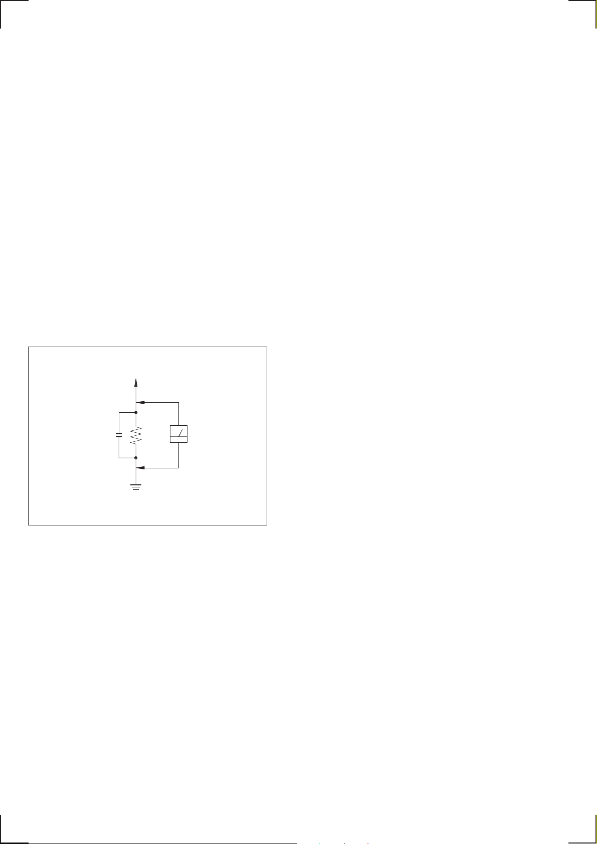
LEAKAGE TEST
The AC leakage from any exposed metal part to earth ground and
from all exposed metal parts to any exposed metal part having a
return to chassis, must not exceed 0.5mA (500 microampers).
Leakage current can be measured by any one of three methods.
1. A commercial leakage tester, such as the Simpson 229 or RCA
TW-540A. Follo w the manufacturers' instructions to use these
instruments.
2. A battery-operated A C milliammeter. The Data Precision 245
digital multimeter is suitable for this job.
3. Measuring the voltage drop across a resistor by means of a
VOM or battery-operated AC v oltmeter. The "limit" indication
is 0.75V, so analog meters must have an accurate lo w v oltage
scale. The Simpson 250 and Sanwa SH-63Trd are examples
of a passive VOM that is suitable. Nearly all battery operated
digital multimeters that have a 2V A C range are suitable. (See
Fig. A)
Earth Ground
Fig. A. Using an A C v oltmeter to check A C leakage.
SAFETY-RELATED COMPONENT WARNING!!
COMPONENTS IDENTIFIED BY MARK ! OR DOTTED LINE WITH
MARK ! ON THE SCHEMATIC DIAGRAMS AND IN THE PARTS
LIST ARE CRITICAL TO SAFE OPERATION. REPLACE THESE
COMPONENTS WITH SONY PARTS WHOSE PART NUMBERS
APPEAR AS SHOWN IN THIS MANUAL OR IN SUPPLEMENTS
PUBLISHED BY SONY.
ATTENTION AU COMPOSANT AYANT RAPPORT
À LA SÉCURITÉ!
LES COMPOSANTS IDENTIFÉS P AR UNE MARQUE ! SUR LES
DIAGRAMMES SCHÉMA TIQUES ET LA LISTE DES PIÈCES SONT
CRITIQUES POUR LA SÉCURITÉ DE FONCTIONNEMENT. NE
REMPLACER CES COMPOSANTS QUE PAR DES PIÈSES SONY
DONT LES NUMÉROS SONT DONNÉS DANS CE MANUEL OU
DANS LES SUPPÉMENTS PUBLIÉS PAR SONY.
— 2 —

TABLE OF CONTENTS
SERVICE NOTE
1. ERROR CODE INDICATION··········································· 4
1. GENERAL
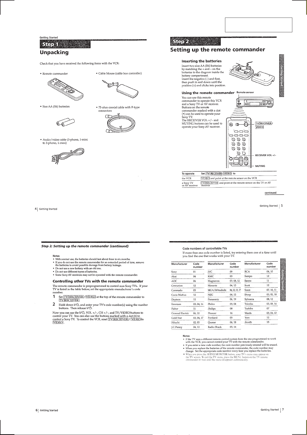
Getting Started
Unpacking ···········································································1-1
Setting up the remote commander·······································1-1
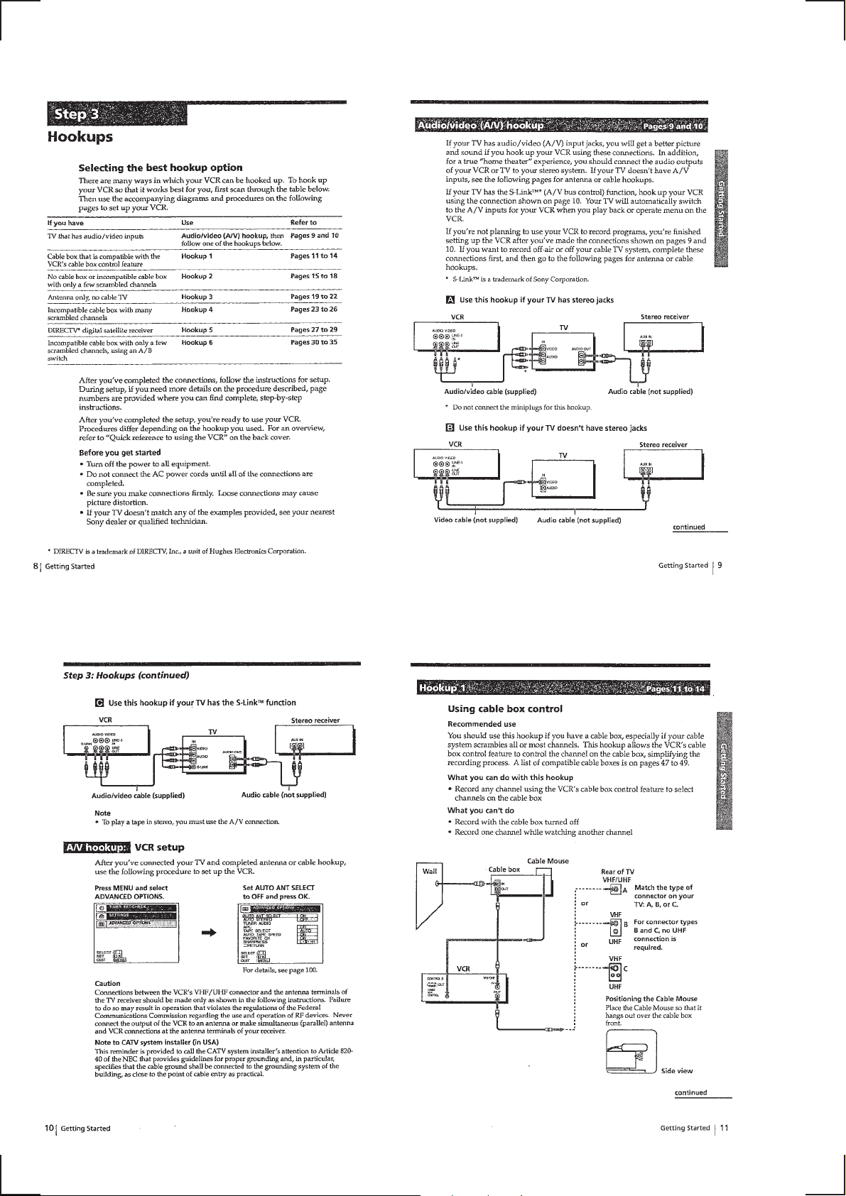
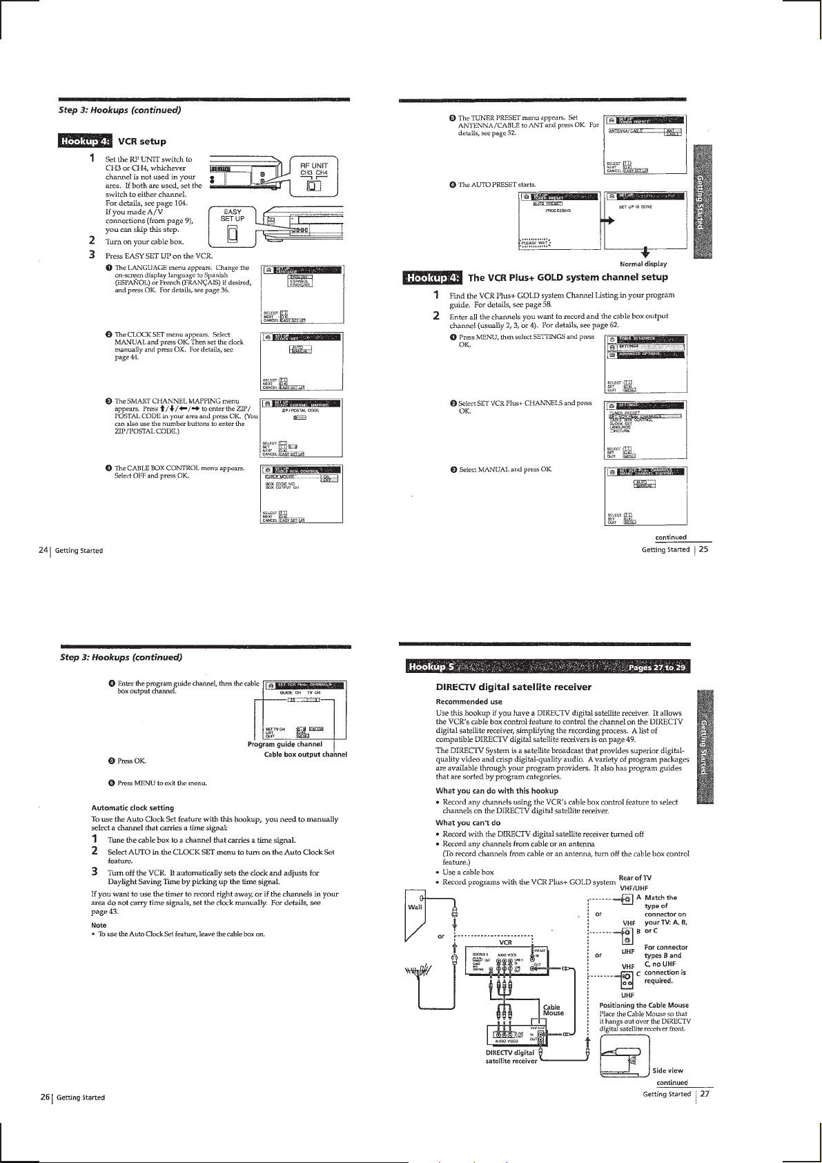
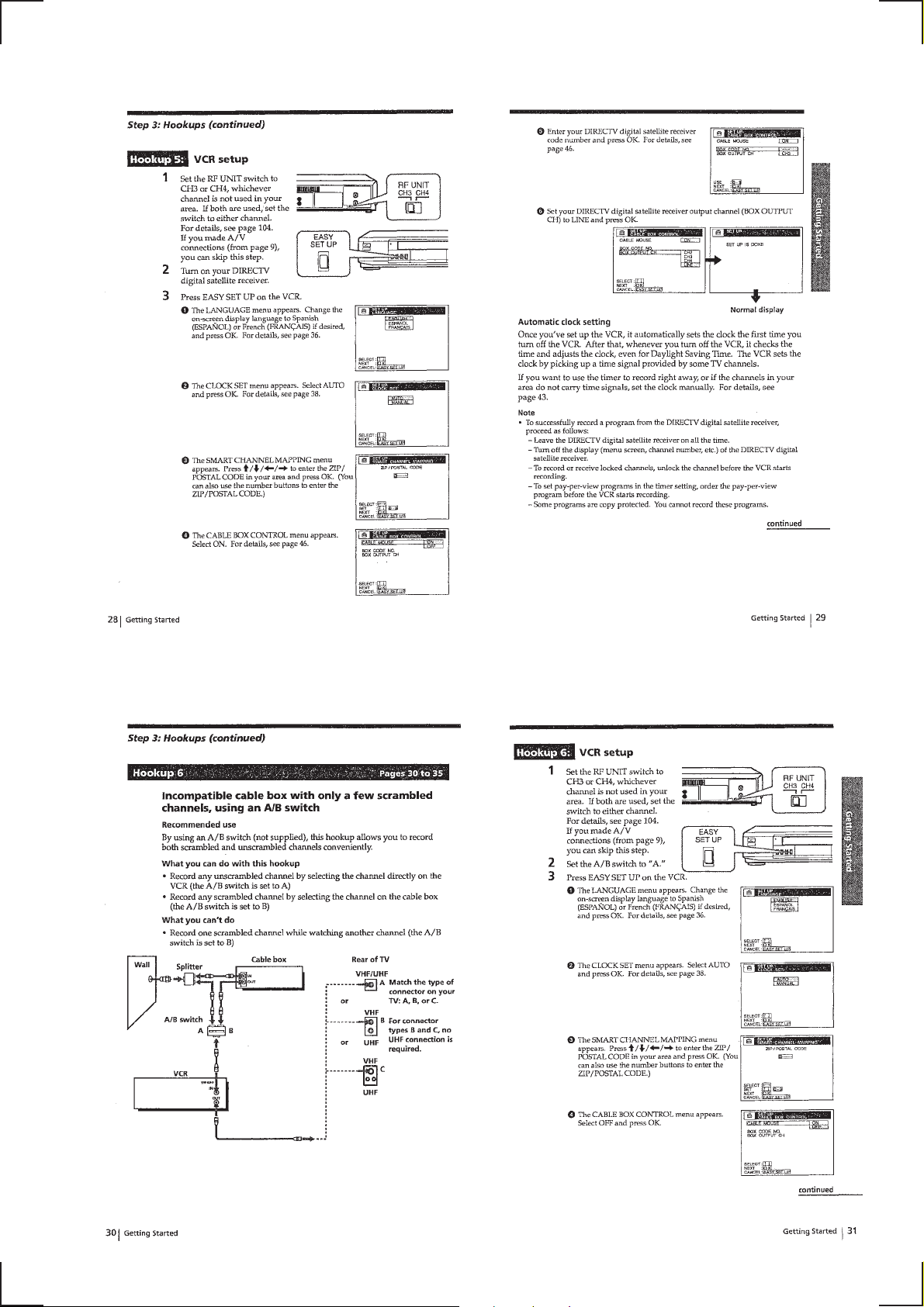
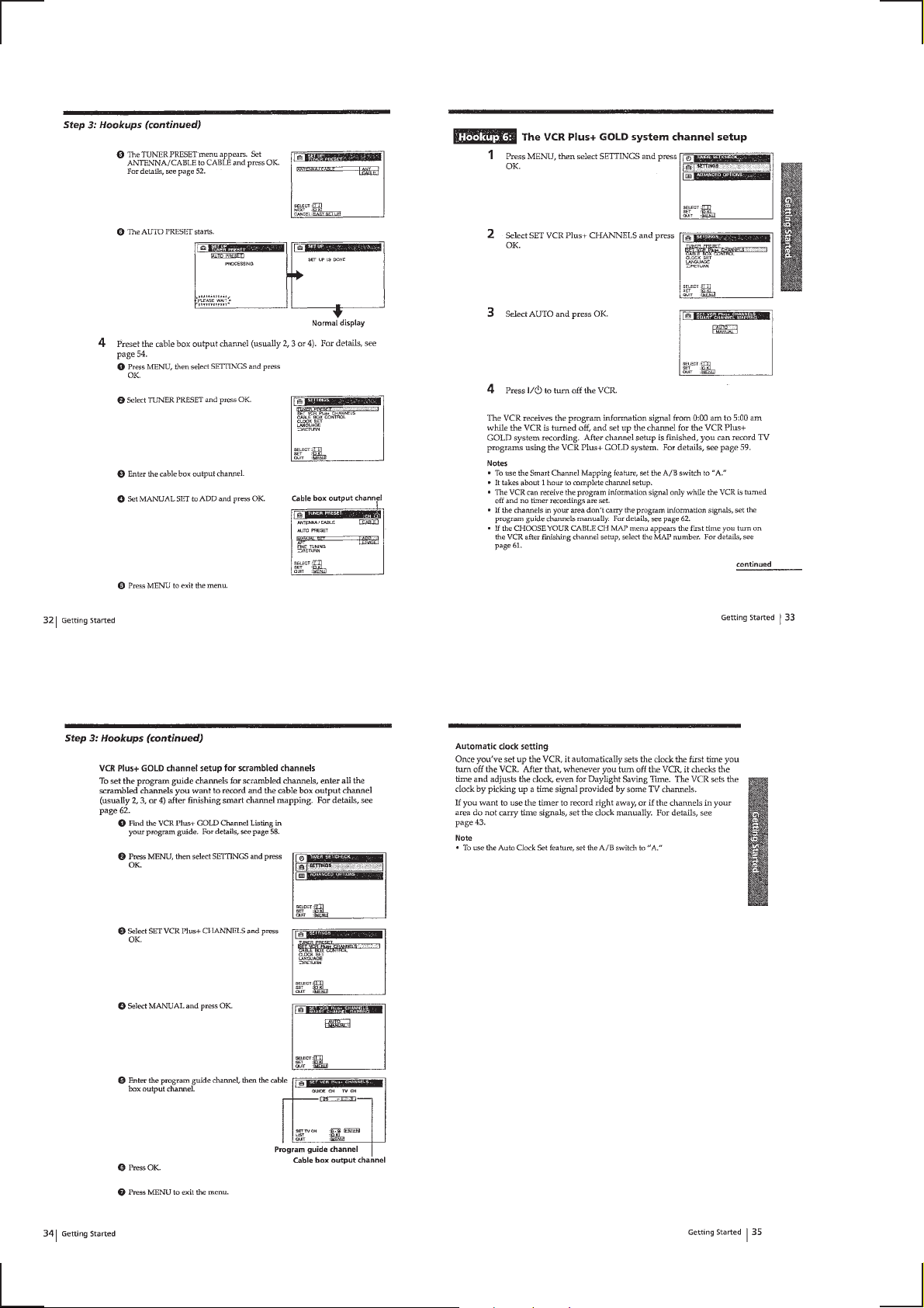
Hookups ··············································································1-2
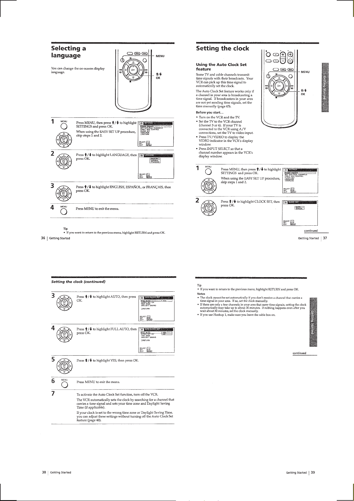
Selecting a language···························································· 1-9
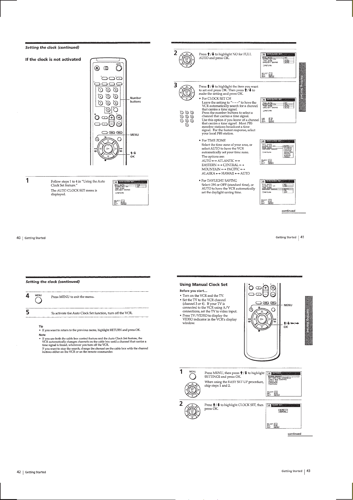
Setting the clock ··································································1-9
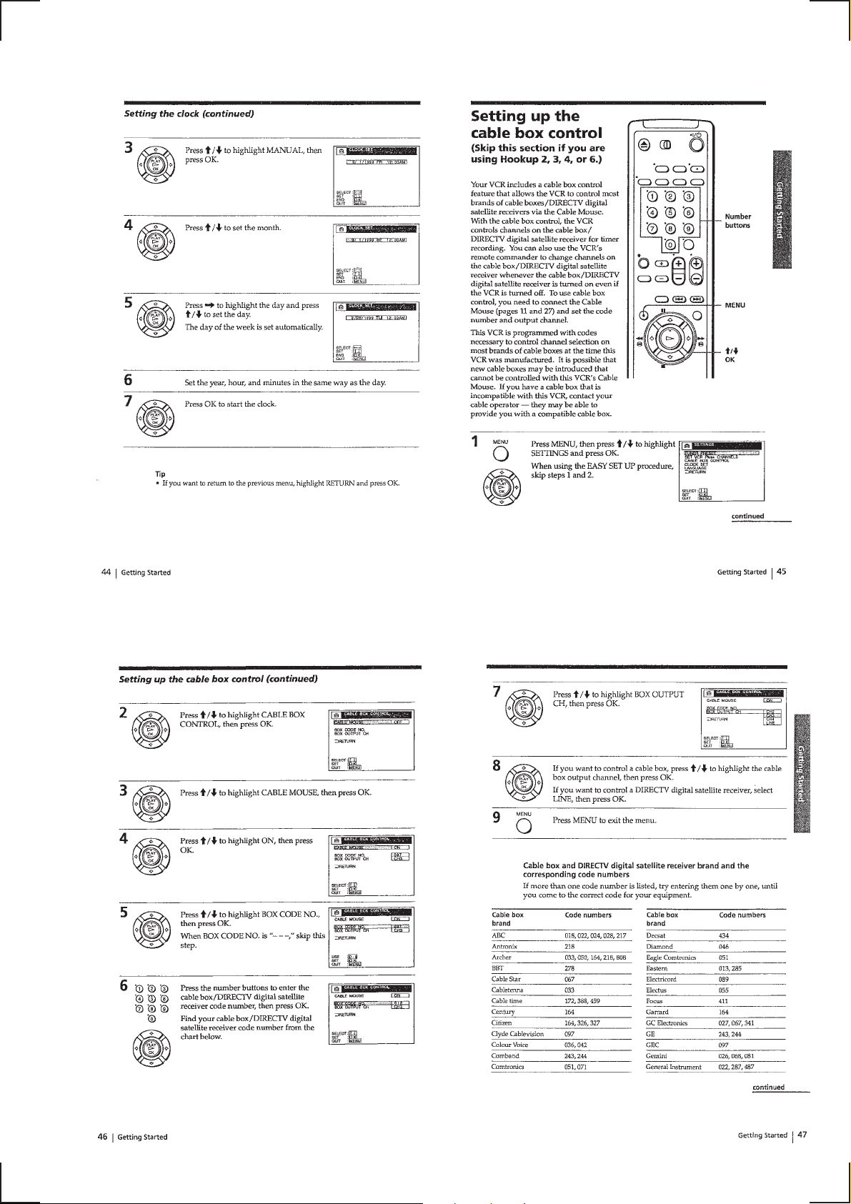
Setting up the cable box control ········································1-11
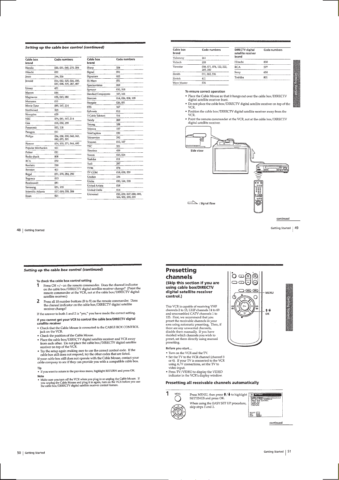
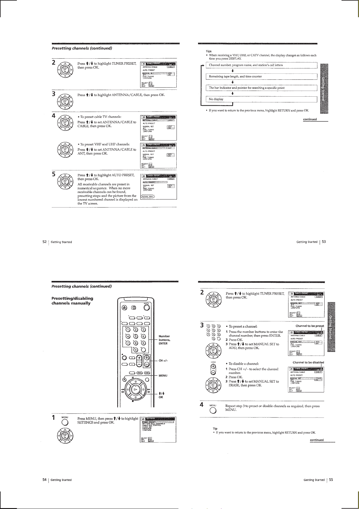
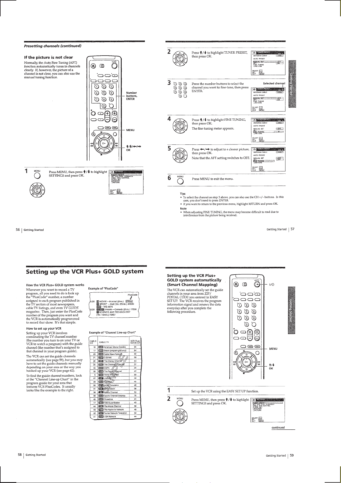
Presetting channels ····························································1-12
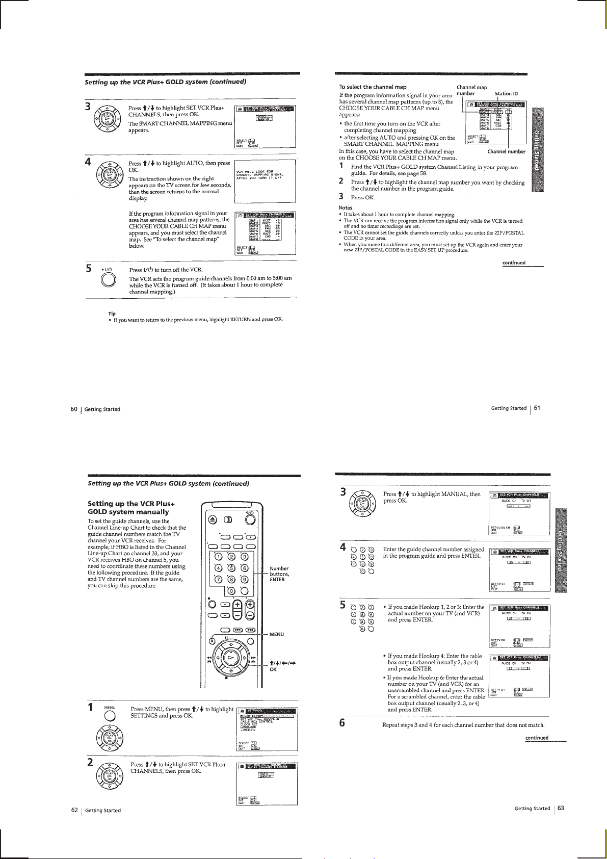
Setting up the VCR Plus+ GOLD system ························· 1-14
Basic Operations
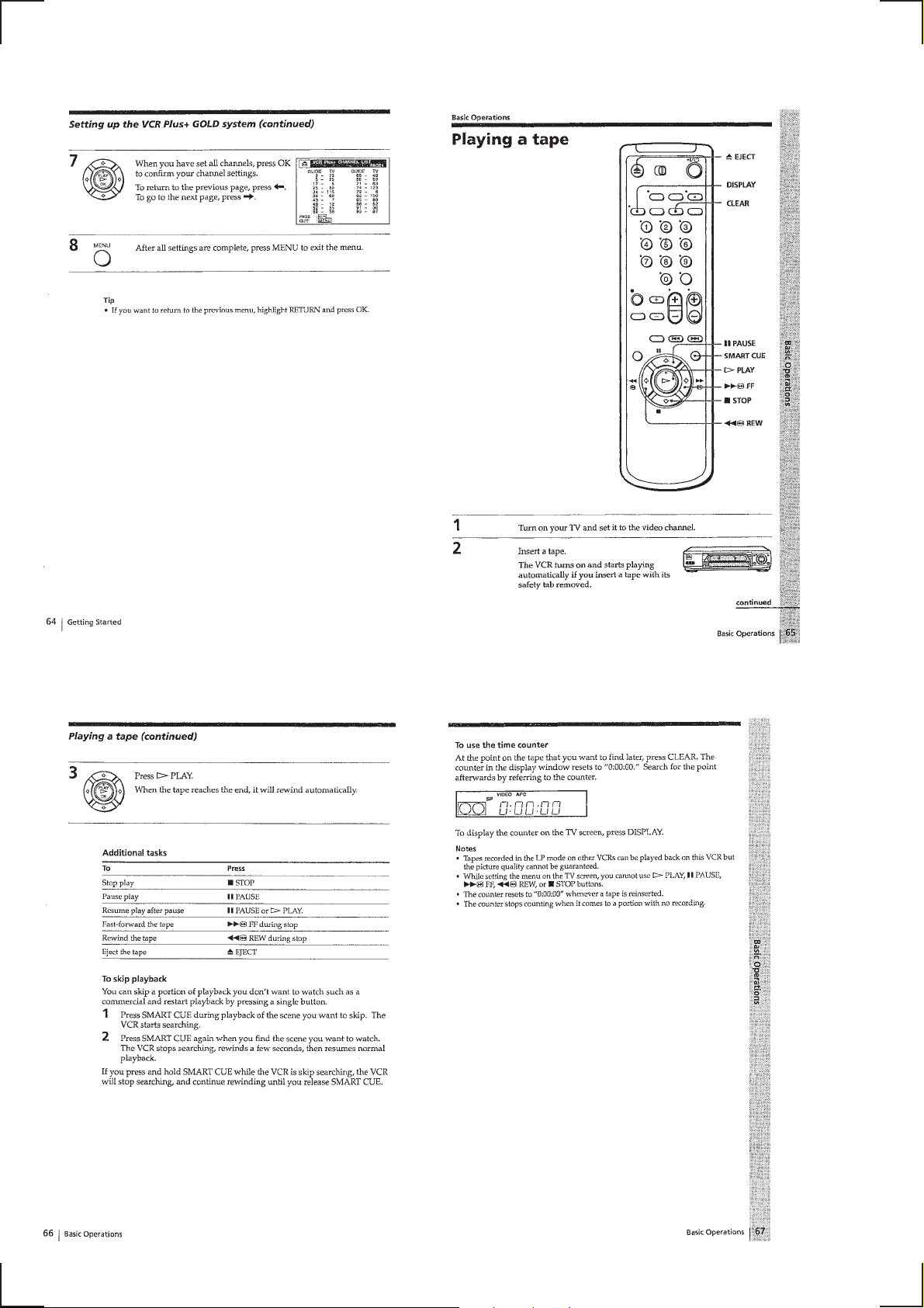
Playing a tape ····································································1-16
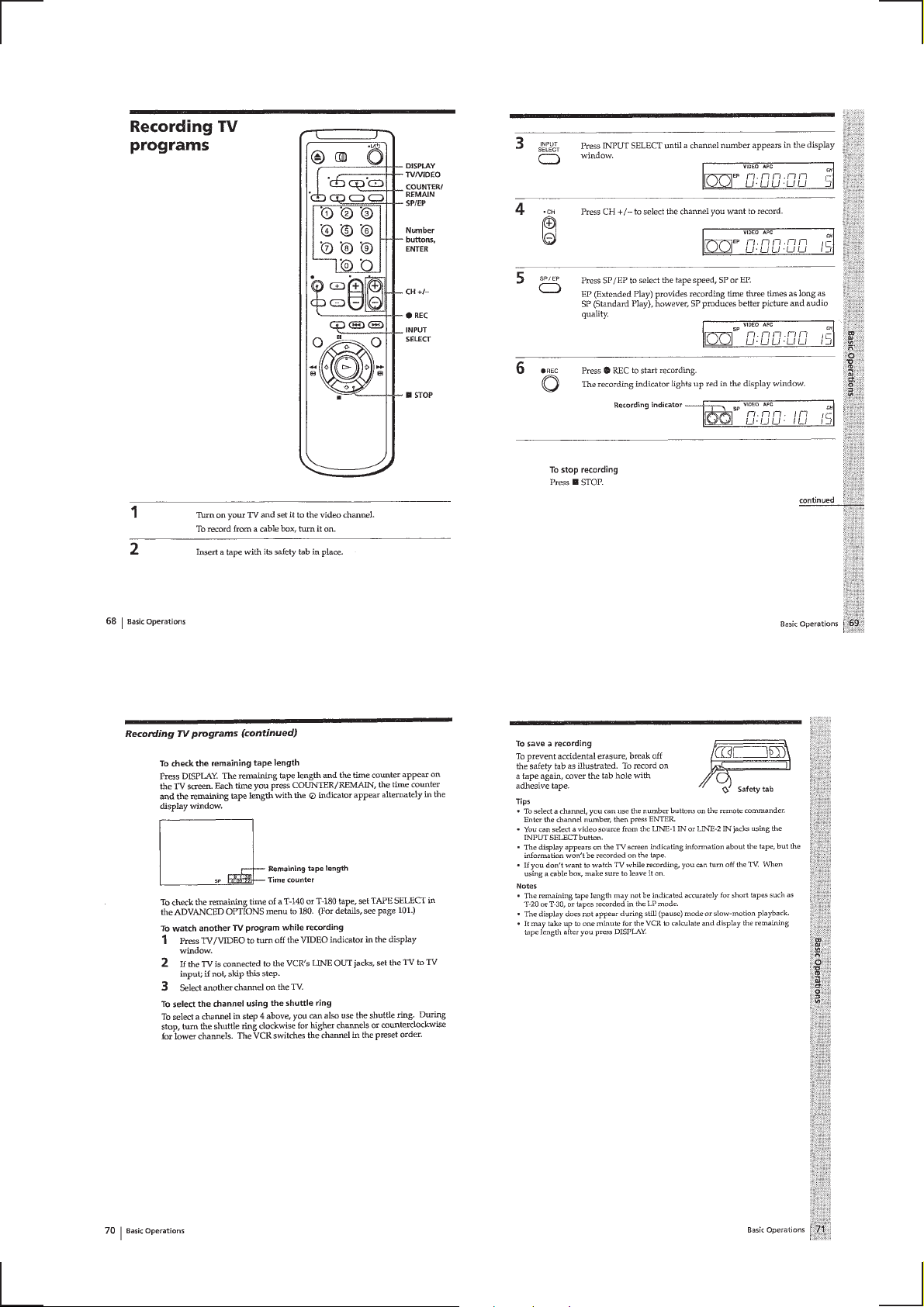
Recording TV programs ····················································1-17
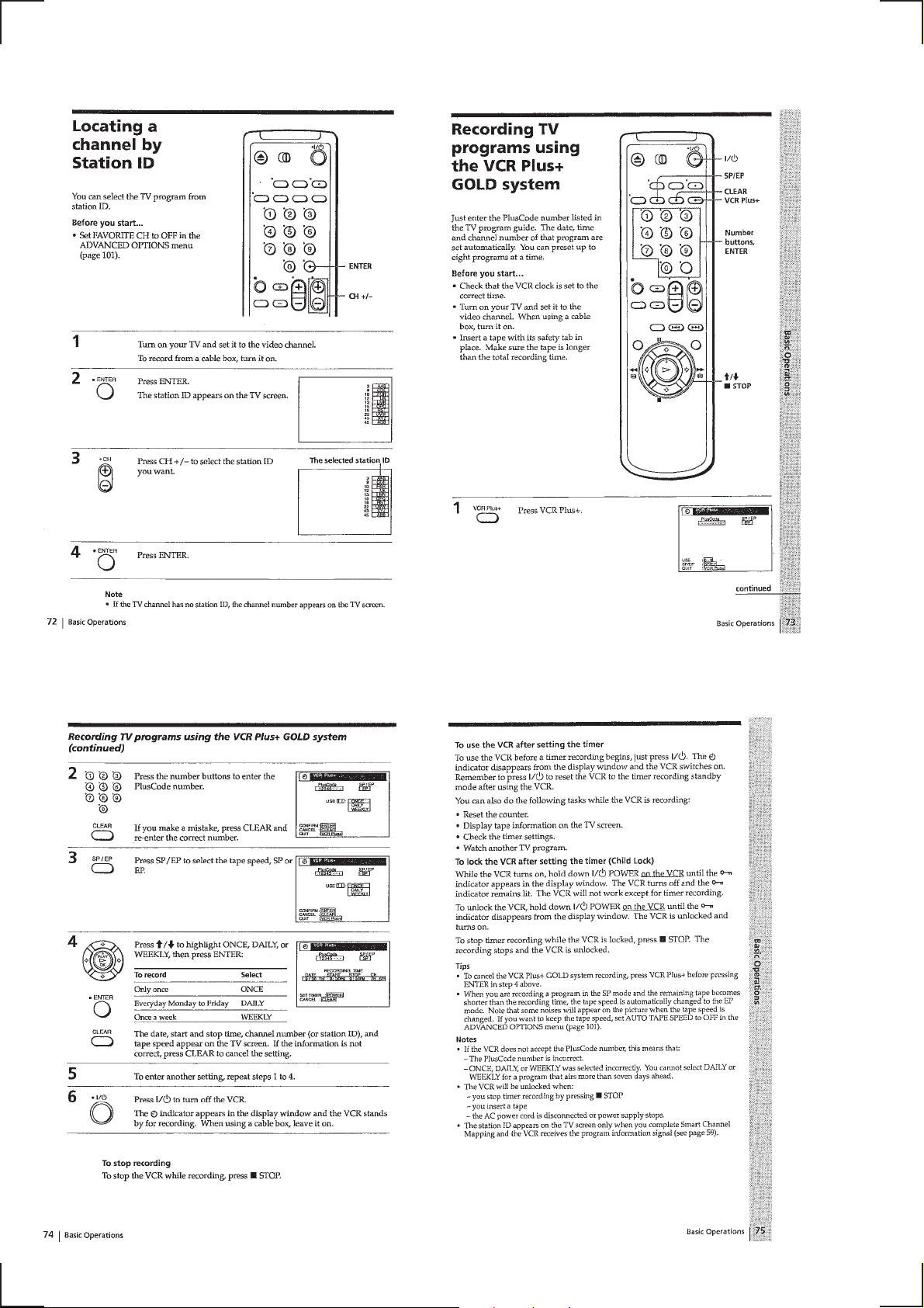
Locating a channel by Station ID······································1-18
Recording TV programs using
the VCR Plus+ GOLD system ··········································1-18
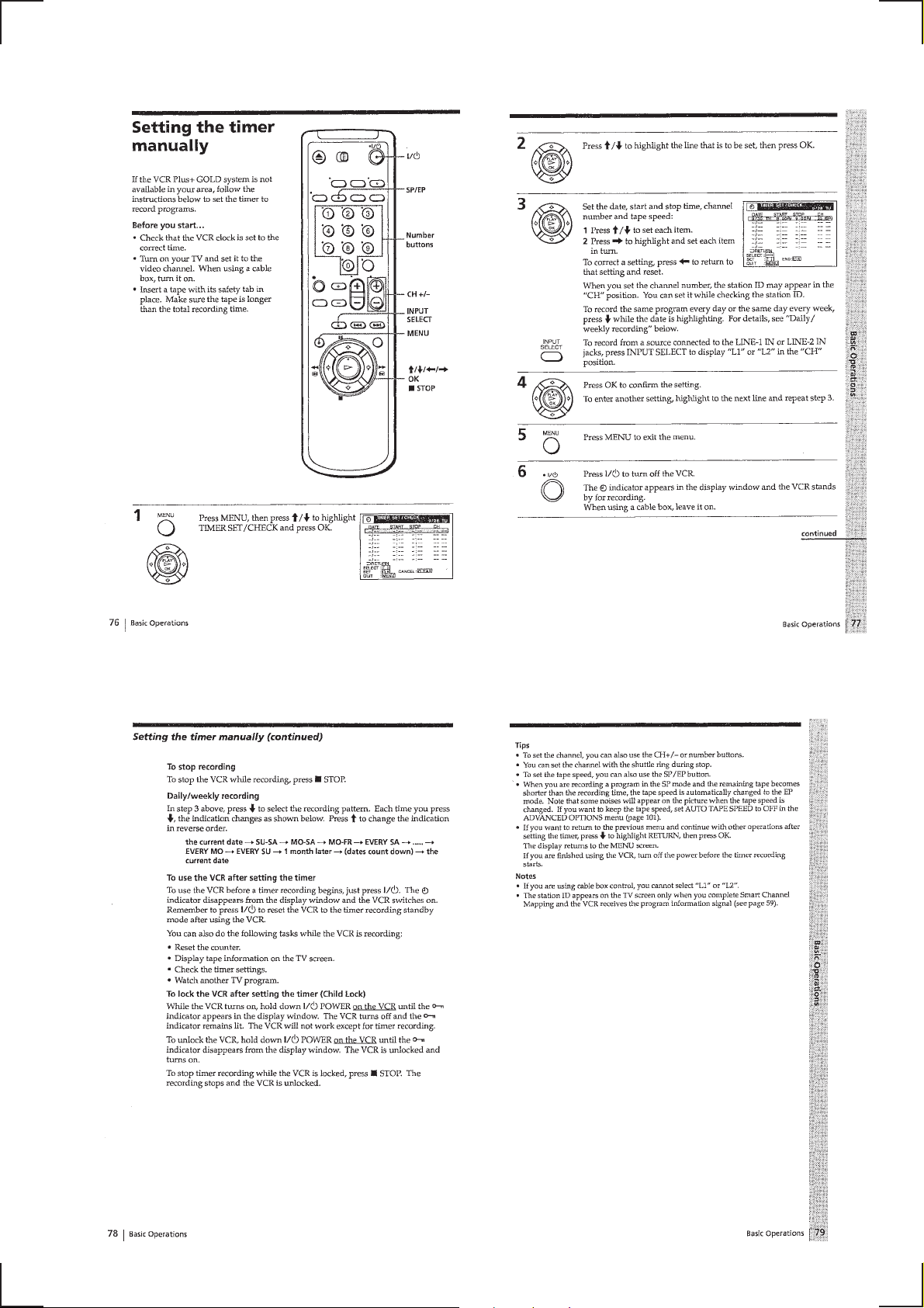
Setting the timer manually ················································1-19
Additional Operations
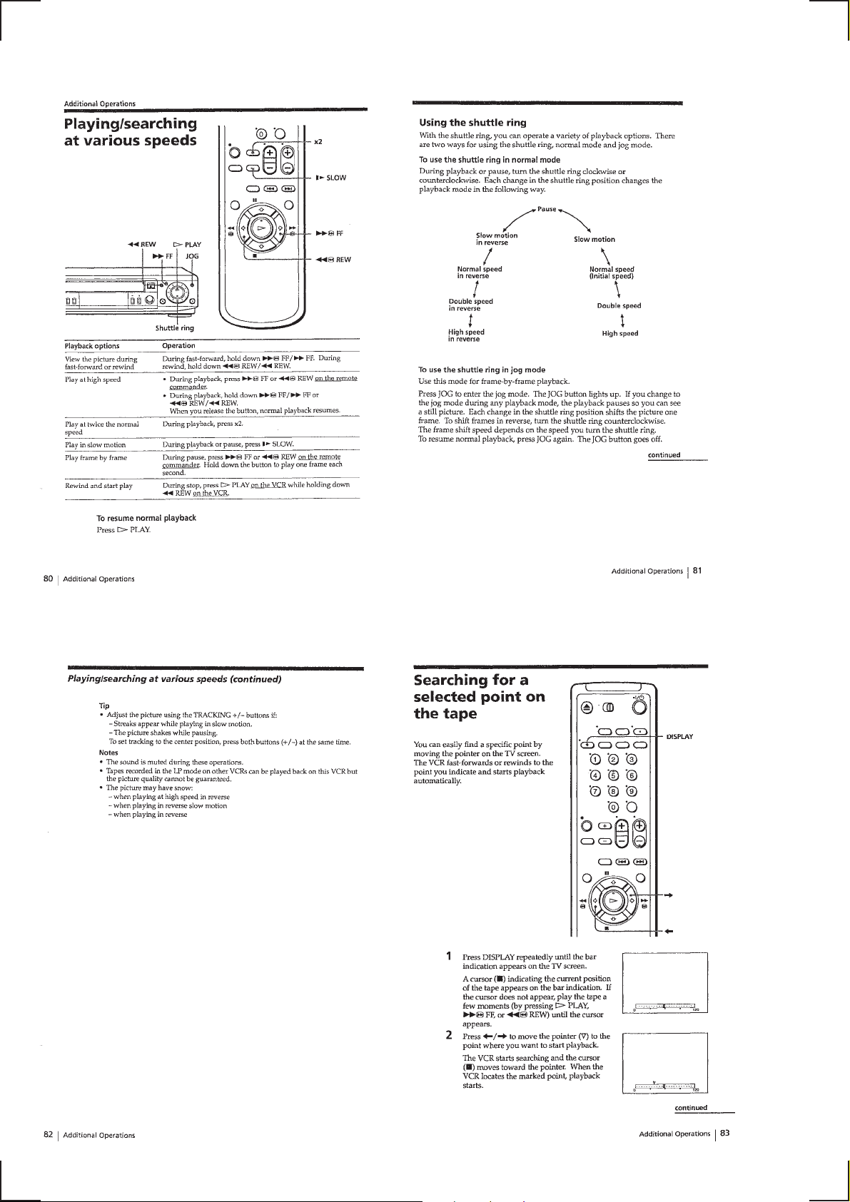
Playing/searching at various speeds··································1-20
Searching for a selected point on the tape························· 1-20
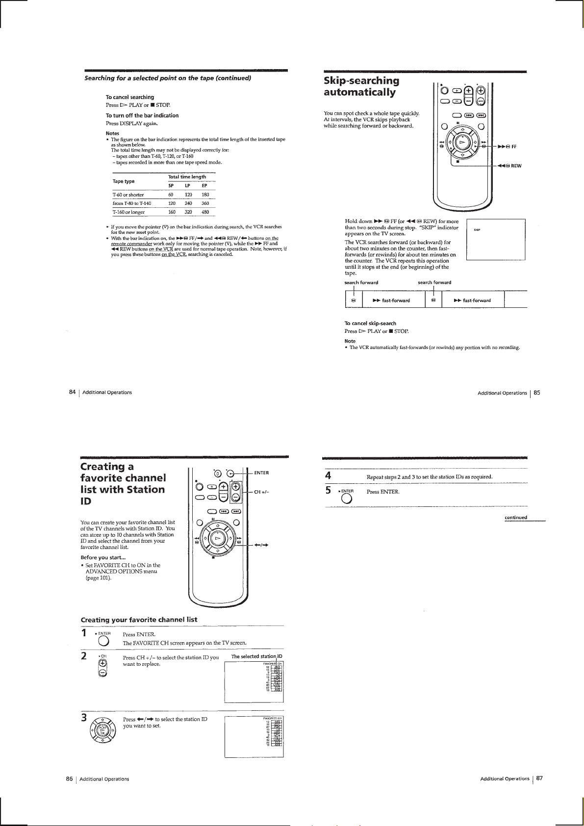
Skip-searching automatically ············································1-21
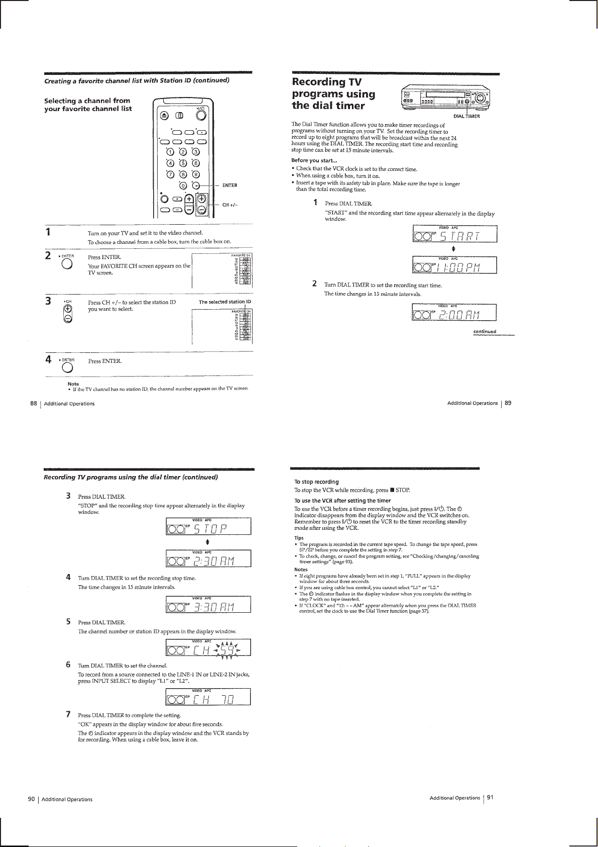
Creating a favorite channel list with Station ID ················1-21
Recording TV programs using the dial timer····················1-22
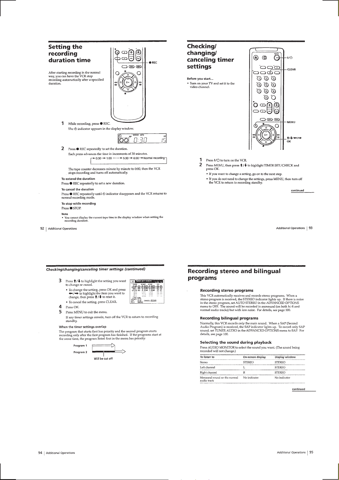
Setting the recording duration time···································1-23
Checking/changing/canceling timer settings·····················1-23
Recording stereo and bilingual programs ·························1-23
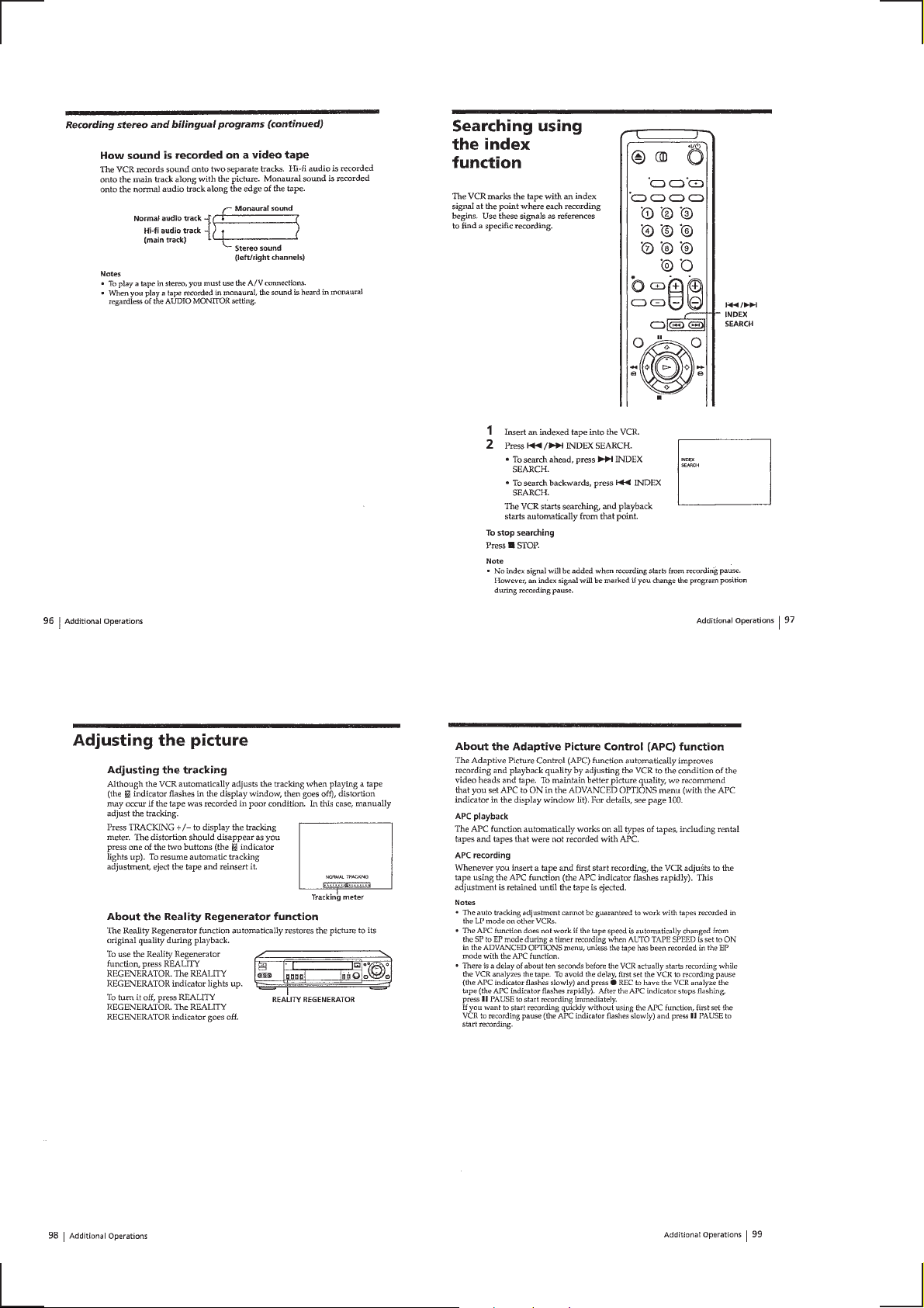
Searching using the index function ···································1-24
Adjusting the picture ·························································1-24
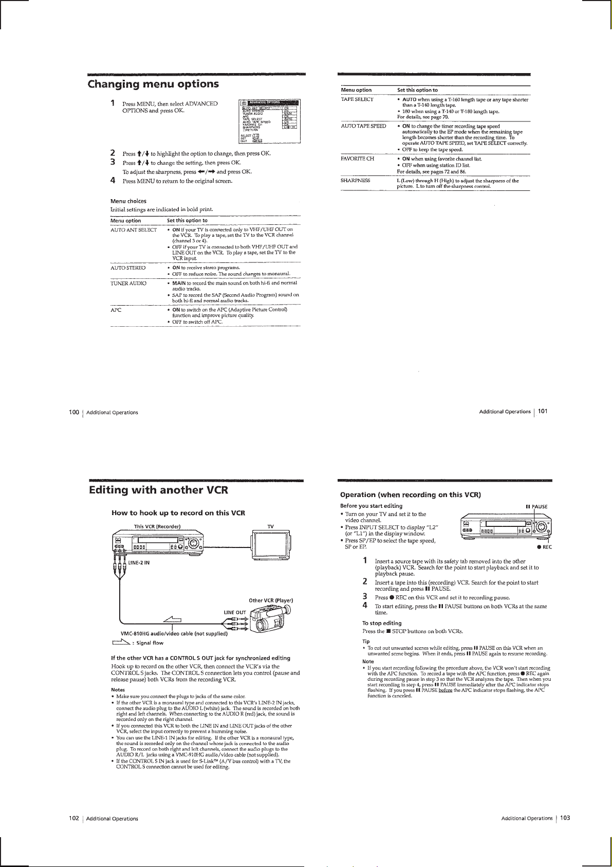
Changing menu options·····················································1-25
Editing with another VCR················································· 1-25
Additional information
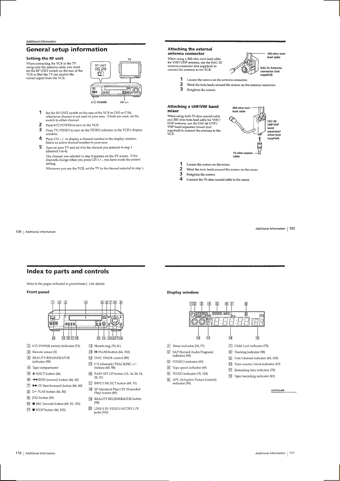
General setup information ·················································1-26
Index to parts and controls ················································1-26
2. DISASSEMBLY
2-1. CASE, FRONT PANEL BLOCK ASSEMBLY ··············2-1
2-2. MF-316 BOARD, DM-84 BOARD, DI-71 BOARD ······2-1
2-3. REAR PANEL ·································································2-2
2-4. MA-342 BOARD ····························································2-2
2-5. MECHANISM DECK····················································· 2-3
2-6. INTERNAL VIEWS························································2-4
2-7. CIRCUIT BOARDS LOCATION ···································2-5
3. BLOCK DIAGRAMS
3-1. OVERALL BLOCK DIAGRAM ····································3-1
3-2. VIDEO BLOCK DIAGRAM ··········································3-3
3-3. SERVO/SYSTEM CONTROL/TUNER
BLOCK DIAGRAM ·······················································3-5
3-4. AUDIO BLOCK DIAGRAM ··········································3-7
3-5. POWER BLOCK DIAGRAM········································· 3-9
4. PRINTED WIRING BOARDS AND
SCHEMATIC DIAGRAMS
4-1. FRAME SCHEMATIC DIAGRAM································4-3
4-2. PRINTED WIRING BOARDS AND SCHEMATIC
DIAGRAMS···································································· 4-5
• MA-342 (VIDEO, AUDIO, SERVO/SYSTEM
CONTROL,TUNER) PRINTED WIRING BOARD ··4-5
• MA-342 (1/8) (REC/PB AMP) SCHEMATIC
DIAGRAM ··································································4-7
• MA-342 (2/8) (VIDEO/AUDIO) SCHEMATIC
DIAGRAM ··································································4-9
• MA-342 (3/8) (SERVO/SYSTEM CONTROL)
SCHEMATIC DIAGRAM·········································4-11
• MA-342 (4/8) (AUDIO)
SCHEMATIC DIAGRAM·········································4-13
• MA-342 (5/8) (TUNER) SCHEMATIC
DIAGRAM ································································4-15
• MA-342 (6/8) (FRONT) SCHEMATIC
DIAGRAM ································································4-17
• MA-342 (7/8) (POWER SUPPLY) SCHEMATIC
DIAGRAM ································································4-19
• MA-342 (8/8) (V SET) SCHEMATIC DIAGRAM ··4-21
• DM-84 (TAPE OPERATION) PRINTED
WIRING BOARD ·····················································4-23
• DM-84 (TAPE OPERATION) SCHEMATIC
DIAGRAM ································································4-24
• MF-316 (POWER, EJECT SWITCH) PRINTED
WIRING BOARD ·····················································4-25
• MF-316 (POWER, EJECT SWITCH) SCHEMATIC
DIAGRAM ································································4-26
• DI-71 (DIAL TIMER SWITCH) PRINTED WIRING
BOARD AND SCHEMATIC DIAGRAM ················4-27
• AR-20 (ARC) PRINTED WIRING BOARD AND
SCHEMATIC DIAGRAM·········································4-28
5. INTERFACE, IC PIN FUNCTION
DESCRIPTION
5-1. SYSTEM CONTROL — MECHANISM BLOCK
INTERFACE (MA-342 BOARD IC160) ························ 5-1
5-2. SYSTEM CONTROL — SERVO PERIPHERAL
CIRCUIT INTERFACE (MA-342 BOARD IC160) ·······5-1
5-3. SYSTEM CONTROL — SYSTEM CONTROL
PERIPHERAL CIRCUIT INTERFACE
(MA-342 BOARD IC160)··············································5-2
5-4. SYSTEM CONTROL AND RF MODULATOR
— INPUT SELECTION BLOCK INTERFACE
(MA-342 BOARD IC160)···············································5-2
5-5. SYSTEM CONTROL — VIDEO/RP BLOCK
INTERFACE (MA-342 BOARD IC160) ························ 5-2
5-6. SYSTEM CONTROL — AUDIO BLOCK INTERFACE
(MA-342 BOARD IC160)···············································5-2
5-7. SERVO/SYSTEM CONTROL MICROPROCESSOR
PIN FUNCTIONS (MA-342 BOARD IC160)················5-3
6. ADJUSTMENTS
6-1 MECHANICAL ADJUSTMENTS ·································6-1
6-2. ELECTRICAL ADJUSTMENTS ···································6-1
2-1. PREPARATION BEFORE ADJUSTMENT ···················6-1
2-1-1.Equipment Required ························································6-1
2-1-2.Equipment Connection ····················································6-1
2-1-3.Set-up of Adjustment·······················································6-1
2-1-4.Alignment Tape ·······························································6-1
2-1-5.Input/Output Levels and Impedance ······························· 6-2
2-1-6.Adjustment Sequence ······················································6-2
2-2. POWER SUPPLY CHECK ·············································6-2
2-2-1.Output Voltage Check (MA-342 Board) ·························6-2
2-3. SERVO SYSTEM CHECK ·············································6-3
2-3-1.RF Switching Position Adjustment (MA-342 Board) ·····6-3
2-4. AUDIO SYSTEM ADJUSTMENT·································6-3
2-4-1.Hi-Fi Audio System Adjustment (Hi-Fi model only) ······6-3
2-4-2.Hi-Fi Switching Position Adjustment
(MA-342 Board)······························································6-4
2-4-3.Normal Audio System Adjustment··································6-4
2-4-4.ACE Head Adjustment ···················································· 6-4
2-4-5.E-E Output Level Check ·················································6-4
2-4-6.Frequency Response Check·············································6-4
2-5. ADJUSTING PARTS LOCATION DIAGRAM ·············6-6
7. REPAIR PARTS LIST
7-1 EXPLODED VIEWS ······················································ 7-1
7-1-1.FRONT PANEL AND UPPER CASE SECTION ··········7-1
7-1-2.CHASSIS SECTION·······················································7-2
7-1-3.MECHANISM DECK SECTION-1 ·······························7-3
7-1-4.MECHANISM DECK SECTION-2 ·······························7-4
7-1-5.MECHANISM DECK SECTION-3 ·······························7-5
7-2. ELECTRICAL PARTS LIST ··········································7-6
— 3 —
SER VICE NOTE
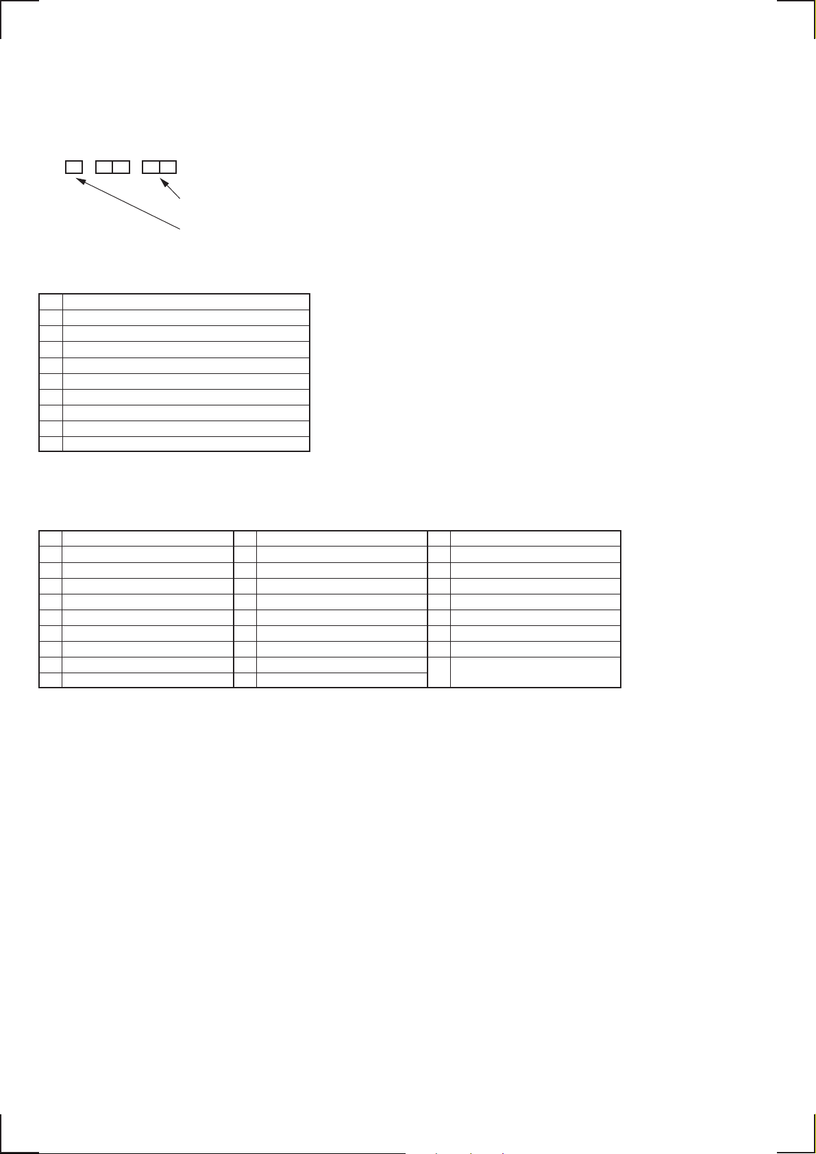
1. ERROR CODE INDICATION
• Error codes are indicated using the lower 5 digits in the fluorescent display tube.
“At this time, Colon “:” between character is not indicated.”
Mode code indication when the error has occurred.
Error code
ERROR CODE
0 No error
1 Cam encoder error Loading direction
2 Cam encoder error Unloading direction
3 T reel error
4 S reel error
5 Capstan error
6 Drum error
7 Error on initializing
8 Cassette loading error
9 Reserve
MODE CODE
0 Power-on eject 10 FWD x1 20 REW play
1 P ower-on initial 11 FWD x2 21 Cas. loading
2 Power-off eject 12 CUE 22 Tape loading
3 Power-off stop 13 PB-pause 23 Power-off loading
4 FF 14 RVS-pause 24 Mecha. error (Power on)
5 REW 15 RVS x1 25 Power-on eject initial
6 REC 16 RVS x2 26 Power-off eject initial
7 REC- pause 17 REV 27 APC REC
8 P ower-on stop 18 Power-off initial 28 Cas. loading
9 PB 19 Mecha. error (Power off) (No auto PB check)
— 4 —
SECTION 1
GENERAL
SLV-789HF/792HF/799HF
This section is extracted from
instruction manual.
1-1
1-2
1-3
1-4
1-5
1-6
1-7
1-8
1-9
1-10
1-11
1-12
1-13
1-14
1-15
1-16
1-17
1-18
1-19
1-20
1-21
1-22
1-23
1-24
1-25
1-26
 Loading...