

Sony SLV-789HF User Manual
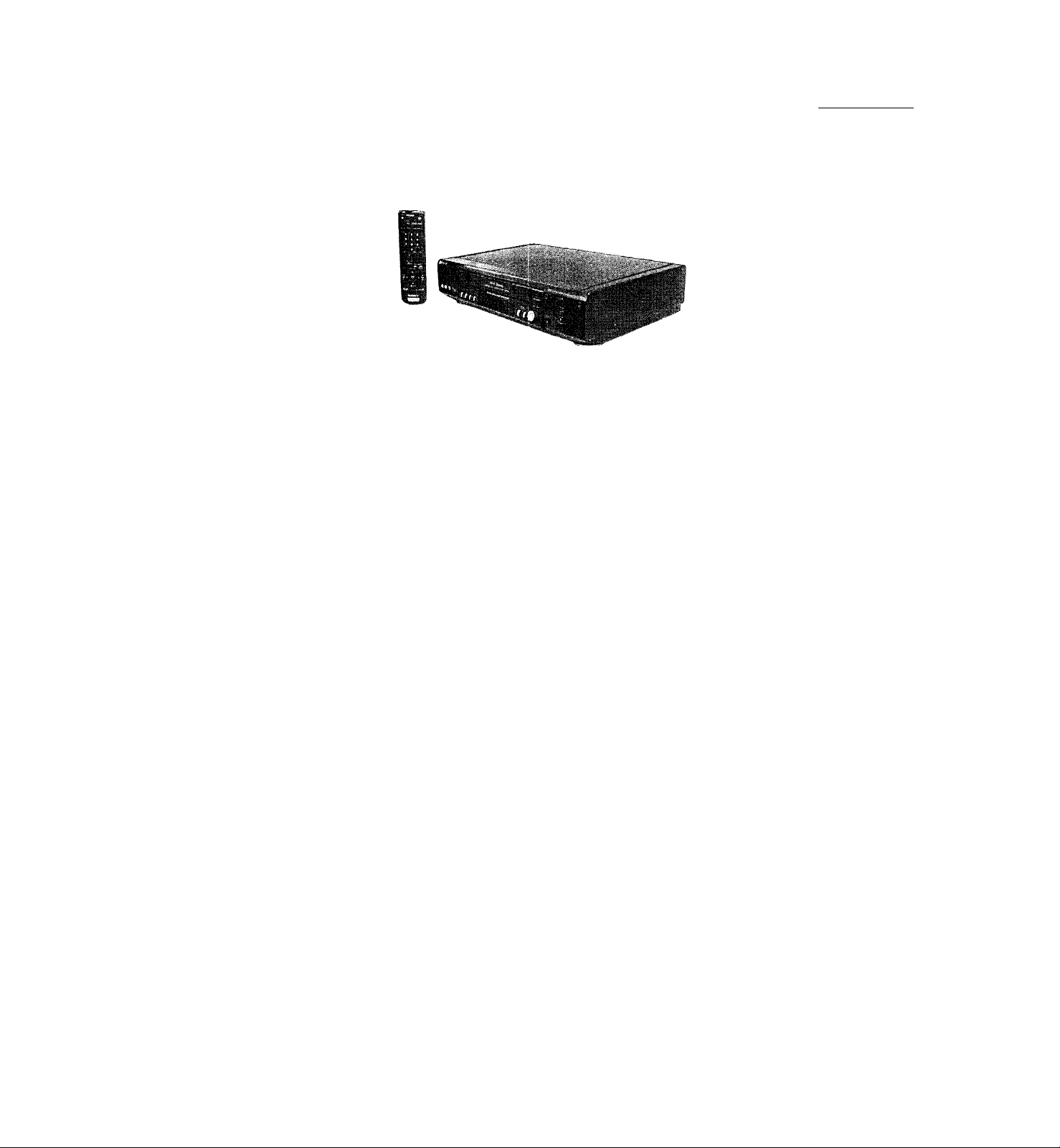
SLV-789HF/792HF/799HF
RMT-V267A
c SERVICE MANUAL
Photo: SLV-799HF
RMT-V267A
Refer to the SERVICE MANUAL of VMS MECHANICAL ADJUSTMENT VI for MECHANICAL ADJUSTMENTS. (9-921-647-11)
SPECIFICATIONS
US Model
SLV-789HF/799HF
Canadian Model
SLV-789HF/792HF/799HF
VMS
S MECHANISM
System
K.
ForiTia i
VHS NTSC Standard
Video I'ecording system
Rotary head helical scanning FM system
Video heads
Double azimuth four heads
Video .signal
NrSC color, EIA standards
Tape s]5ced
SF'; 3335 mm/s (1 Vs inches/s)
FI': 11.11 mm/s (^/i6Ìnches/s)
LI’: 16.67mm/s (“/u inches/s),
playback only
record ing/playback time
8 lu^. in EP mode (with T-160 tape)
Fast-forward and rewind time
A|iprox. 3 min. (with T-120 tape)
Tuner section
Channel coverage
Vl-IF2tol3
13TF 14 to 69
C/'lTV A-8 to A-1, A to W, W-(-l to W-t-84
Antenna
75-ohm antenna terminal for VHF/UHF
Inputs and outputs
LINE-1 IN and -2 IN
VIDEO IN, phono jack (1 each)
Input signal: 1 Vp-p, 75 ohms, unbalanced,
sync negative
AUDIO IN, phono jacks (2 each)
Input level: 327 irVrms
Input impedcmce: more than 47 kilohms
LINE OUT
VIDEO OUT, phono jack (1)
Output signal: 1 Vp-p, 75 ohms, unbalanced,
sync negative
AUDIO OUT, phono jacks (2)
Standard output .327 mVrms
Load impedance; 47 kilohms
Output impedance: less than 10 kilohms
S-LINK (CONTROL S IN) (SI .V-792HF/799HK)
Minijack (1)
CABLE BOX CONTROL (CONTROL S OUT)
Stereo mini jack (j)lug in p>ower) (1)
Timer section
Clock
Quartz locked
Timer indication
12-hour cycle
Timer setting
8 programs per month (max.)
Tower back-up
Built-in self-charging capacitor
Back-up duration: up to 1 hour at a time
General
Power requirements
l20VAC,60Hz
Power consumption
24 W
Operating temperature
5®Cto4(PC(4rFtol04®F)
Storage temperature
-20'’C to 60"C (^“F to 140"F)
Dimensions
Approx. 430 X 100 X 292.5 mm (w/h/d)
(Approx. 17 X 4 X 11 V« inches) including
projecting parts and controls
Mass
Approx. 4.1 kg (9 lb 1 oz)
Supplied accessories
Remote commander (1)
Size AA (R6) batteries (2)
75-ohm coaxial cable with F-type connectors (1)
Audio/video cable (3-phono, 1-mini to 3-phono,
1-mini) (1) (SLV-792HH7799HH)
Cable Mouse (cable box controller) (1)
Design and specifications are subject to diange
without notice.
ENERGY Star is a U3. registered mark.
As an Energy Star Partner, Sony Corporation
has determined that tills product meets the
ENERGY Star guidelines for energy efficiency.
(SI .V-/97HF/799HF)
VIDEO CASSETTE RECORDER

1
c
L ^
TABLEE OF
SERVICE NOTE
I. HRROR CODE INDICATION
1. GENERAL
Gelling Slaricd
U ipacking ...............................................................................
Selling up Ihe reinóle commander
Hookups ...................................................................................
Seleeling a language..............................................................
Selling llie clock
Selling up ihe cable box eonlrol
I’leselling channels.............................................................. I
Selling up lire VCR Plus-t- GOLD system
Basie Operalions
Playing a lape.......................................................................1-16
Recording TV programs.....................................................1-17
Loealing a channel by Slation ID
Recording'TV programs using
ill." VCR Plus-r GOLD syslem
Silling Ihe timer manually ................................................1-19
Addit onal Operations
Playing/searehing at various speeds
Searching for a selected point on the tape.....................1-20
Skip-searching automalieall}............................................1-21
Creating ;i favorile channel list with Slation ID..........1-21
Recording TV programs using the dial timer................1-22
Setling the recording duration time.................................1-22
(’heeking/ehanging/eanceling timer sellings
Recording stereo and bilingual programs
Si-arching using the index function
AiJiusting the picture..........................................................1-24
/■
\
Changing menu options
Frditing with another VCR................................................1-25
Addit onal inlornialion
G'.’iieral setup infonnation
Index to parts and controls ...............................................1-26
....................................................................
......................................................
.....................................
.......................................
...................
....................................
.......................................
...............................
................
.....................
................................
...............................................
2. DISASSEMBLY
2-1. CASH, FRONT PANEL Bl.OCK ASSEMBLY..........2-1
2-2. ME-216 BOARD, DM-84 BOARD, Dl-71 BOARD..2-1
2-2. REAR PANEL
2-4. MA-,242 BOARD
2-5. MECHANISM DECK
2-6. INTERNAL VIEWS
2-7. CIRCUIT BOARDS LOCATION..................................2-5
...................................................................
............................................................
......................................................
.........................................................
3. BLOCK DIAGRAMS
.2-1. OVERALL BLOCK DIAGRAM
2-2. VIDEO Bl.OCK DIAGRAM...........................................2-2
2-2. SERVO/SYSTEM CONTROL/TUNER
BLOC’K DIAGRAM ........................................................2-5
2-4. AUDIO BLOCK DIAGRAM
2-5. POWER BIXX'K DIAGRAM.........................................2-9
...................................
..........................................
4. PRINTED WIRING BOARDS AND
SCHEMATIC DIAGRAMS
4 1. FRAME SC’HEM.ATK' DIAGRAM
4-2. PRIN TED WIRING BOARDS AND SCHEMATIC
DIAGRAMS........................................................................4-5
• MA-242 (VIDEO. AUDIO. SERVO/SYSTEM
CON'TROL.TUNER) PRIN TED WIRING BOARD 4 5
• MA-242 (1/8) (RLCVPB AMP) SCHEMATIC
DIAGRAM .....................................................................4-7
• MA-242 (2/8) (VIDEO/AUDIO) SniHMATIC
DIAGRAM .....................................................................4-9
• MA-242 (.2/8) (SERVO/SY.STEM CON'TROL)
cr M 11 . N 1 A'l'U ' I V I \ CM) \ \ 1 II
............................
-I I
I
-12
-14
I
1-18
1-18
1-20
1-22
1-22
1-24
1-25
1-26
2-2
2-2
2-2
2-4
.2-1
2-7
4-2
M
I -2
1-9
1-9
CONTENTS
• MA-,242 (5/8) ( TUNER) SCHEMATIC
DIAGRAM ..................................................................4-15
• MA-,242 (6/8) (FRONT) SCHEMATIC
DIAGRAM ..................................................................4-17
• MA-242 (7/8) (POWER SUPPLY) SC’IIEMATIC
DIAGRAM ..................................................................4-19
• MA-,242 (8/8) (V SET) SCTIEMA'TIC DIAGRAM •4-21
• DM-84 (TAPE OPERATION) PRINTHT)
W'lRlNG BOARD .....................................................4-22
• DM-84 ( TAPE OPERATION) SC'HFIMATIC
DIAGRAM
• MF-216 (POWTIR, E.IFXT SWIl’CH) PRIN TED
WIRING BOARD
• MF-216 (POWER, EJECT SWITCH) SCHEMATIC
DIAGRAM ..................................................................4-26
• DI-71 (DIAL TIMER SWITCH) PRIN TED WIRING
BOARD AND SCHEMATIC DIAGRAM
• AR-20 (ARC) PRINTED WIRING BOARD AND
SCHEMATJC DIAGRAM
.................................................................
.....................................................
...........
........................................
5. INTERFACE, 1C PIN FUNCTION
DESCRIPTION
5-1. SYSTEM (X)NTROL —MECHANISM BLOCK
IN TERFACE (MA-242 BOARD ICI60)....................5-1
5-2. SY.STEM CONTROL — SERVO PERIPHERAL
CIRCUIT INTERFACE (MA-242 BOARD ICI60)
5-2. SYSTEM CON'TROL — SYSTEM CON'TROL
PERIPHERAL CIRCUIT IN TERFACE
(MA-,242 BOARD K'160).............................................5-2
5-4. SYSTEM CONTROL AND RE MODLII .A'TOR
— INPU T SELECTION BLOCK INTERFACE
(MA-242 BOARD ICI60)
5-5. SYS'TTIM CONTROL — VIDEO/RP BLOC’K
INTERFACE (MA-242 BOARD IC160)
5-6. SYSTEM CONTROL — AUDIO BLOCK INTERFACE
(MA-,242 BOARD IC160)
5- 7. STIRVO/SYS'TEM CONTROL MICROPROC'HSSOR
PIN FUNCTIONS (MA-,242 BOARD 1C 160).........5-2
...............................................
.....................
.............................................
6. ADJUSTMENTS
6- 1 MECHANICAL ADJUSTMENTS
6- 2. ELECTRICAL ADJU,STMENTS ..............................6-1
2-1. PREPARATION BEFORE ADJUSTMEN T
2-1 -1. Equipment Required.....................................................6-1
2-1 -2. Equipment Conneelion.................................................6-1
2-1 -2. Set-up of Adjustment
2-1-4. Alignment Tape
2-1-5. Inpnl/Output Levels and Iinpedanee
2-1 -6. Adjustment Sequenee....................................................6-2
2-2. POWER SLIPPI,Y CHECK
2-2-1 .Output Voltage CJieek (MA-242 Board)
2-2. SERVO SYSTEM CHECK
2-2-1. RF Svvitehing Position Adjustment (MA-242 Board)
2-4. AUDIO SY.STEM ADJUSTMEN T
2-4-1.1 li-F'i Audio Syslem Adjustment (1 li-F'i model only)
2-4-2. Hi-Fi Swilehing Position Adjustment
(MA-242 Board)................................................................6-4
2-4-2. Normal Audio System Adjustment
2-4-4. ,V(’E Head Adjustment ................................................6-4
2-4-5. Fi-lt Onl[)iit Level Cheek ............................................6-4
2-4 6. l-ie(|ueney Response ('heek
2-5. ADJUSTING PARTS LOCATION DTAGRAM
...................................................
..............................................................
..............................................
...............................................
...............................
................
........................
.................
...............................
.............................
..........................................
.........
7. REPAIR PARTS LIST
7- 1 EXPLODED VIEWS
7-1-1. FRONT PANFIL AND UPPER (’ASE SEC TION .7-1
7-1-2.CHASSIS SHCH'ION......................................................7-2
.....................................................
4-24
4-25
4-27
4-28
....
5-2
5-2
5-2
6-1
6-1
6-1
6-1
б-С
6-2
6-2
6-2
6 2
6-4
6-4
6-6
7-1
5-1
.........
.......
6-2
6-2

SAFETY CHECK-OUT
After correcting the original service problem, perform the following
safety checks before releasing the set to the customer.
1. Check the area of your repair for unsoldered or poorly-soldered
connections. Check the entire board surface for solder splashes
and bridges.
2. Check the interboard wiring to ensure that no wires are
"pinched" or contact high-wattage resistors.
3. Look for unauthorized replacement parts, particularly
transistors, that were installed during a previous repair. Point
them out to tlie customer and recommend their replacement.
4. Look for parts which, though functioning, show obvious signs
of deterioration. Point them out to the customer and
recommend their replacement.
.3. Check the line cord for cracks and abrasion.
Recommend the replacement of any such line cord to the
customer.
6. Check tile B-i- voltage to see it is at the values specified.
7. C'lieck the antenna terminals, metal trim, "metallized" knobs,
screws, and all other exposed metal parts for AC leakage.
Check Icakasie as described below.
To Exposed Metal
Parts on Set
\
I . ,- J - ,
0.f5pF= 1.51^1 i /
< .: j ’ I J (U./O V)
AC
LEAKAGETEST
Tile AC leakage from any exposed metal part to earth ground and
from all exposed metal parts to any exposed metal part having a
return to chassis, must not exceed 0..5mA (300 microampers).
Leakage current can be measured by any one of three methods.
1. A commercial leakage tester, such as the Simpson 220 or RC’A
TW-540A. Follow the manufacturers' instrtictions to use these
instruments.
2. A battery-operated AC milliammeter. The Data Precision 243
digital multimeter is suitable for this job.
3. Measuring the voltage drop across a resistor by means of a
VOM or battery-operated AC voltmeter. The "limit" indication
is 0.75V, so analog meters must have an accurate low voltage
scale. The Simpson 250 and Sanwa SH-63Trd are examples
of a passive VOM that is suitable. Nearly all battery operated
digital multimeters that have a 2V AC range arc suitable. (See
Fig. A)
—
Earth Ground
Fig. A. Using an AC voltmeter to check AC leakage.
SAFETY-RELATED COMPONENT WARNING!!
COMPONENTS IDENTIFIED BY MARK /t OR DOTTED LINE WITH
MARK st ON THE SCHEMATIC DIAGRAMS AND IN THE PARTS
LIST ARE CRITICAL TO SAFE OPERATION. REPLACE THESE
COMPONENTS WITH SONY PARTS WHOSE PART NUMBERS
APPEAR AS SHOWN IN THIS MANUAL OR IN SUPPLEMENTS
ATTENTION AU COMPOSANT AYANT RAPPORT
LES COMPOSANTS IDENTIFÉS PAR UNE MARQUE A SUR LES
DIAGRAMMES SCHÉMATIQUES ET LA LISTE DES PIÈCES SONT
CRITIQUES POUR LA SÉCURITÉ DE FONCTIONNEMENT. NE
REMPLACER CES COMPOSANTS QUE PAR DES PIÈSES SONY
DONT LES NUMÉROS SONT DONNÉS DANS CE MANUEL OU
1-ЧАМО I cro c»i 100СЛЯ1ГМТС DI im irQ РДР QOMV
À LA SÉCURITÉ!
SERVICE NOTE
1. ERROR CODE INDICATION
• HiTor codes arc indicated using the lower 5 digits in tlie fluorescent display tube.
"At this time. Colon between chtiracter is not indicated.”
□ CID
Mode code indication when the error htis occurred.
Hrror code
ERROR CODE
0 No error
I Cam encoder error Loading direction
2
Cam encoder error Unloading direction
r reel error
-b
z..
S reel error
Capsttin error
() Drum error
7
Error on initializing
8 Cassette loading error
0
Reserve
MODE CODE
0
Power-on eject lO
Power-on initial
Power-off eject 12 CUE
2
3
I’ower-off stop L3 PB-pause
4 FF I4
.S
RFW
() rf:c 16
7
REC- pause
<s P(rwcr-o/i stop
<)
PB
II FWD x2
15
17 REV
18 Power-off initial
I9
FWD XI
RVS-pause
RVS xl
RVS x2
Media, error (Power off)
20 REW play
Cas. loading
2I
22 Tape loading
23 Power-off loading
Media, error (Power on)
24
Power-on eject initial
25
Power-off eject initial
26
APC REC
27
Cas. loading
28
(No auto PB check)
SECTION 1
GENERAL
SLV-789HF/792HF/799HF
This section is extracted from
instruction manual.
c
A
Getting Started
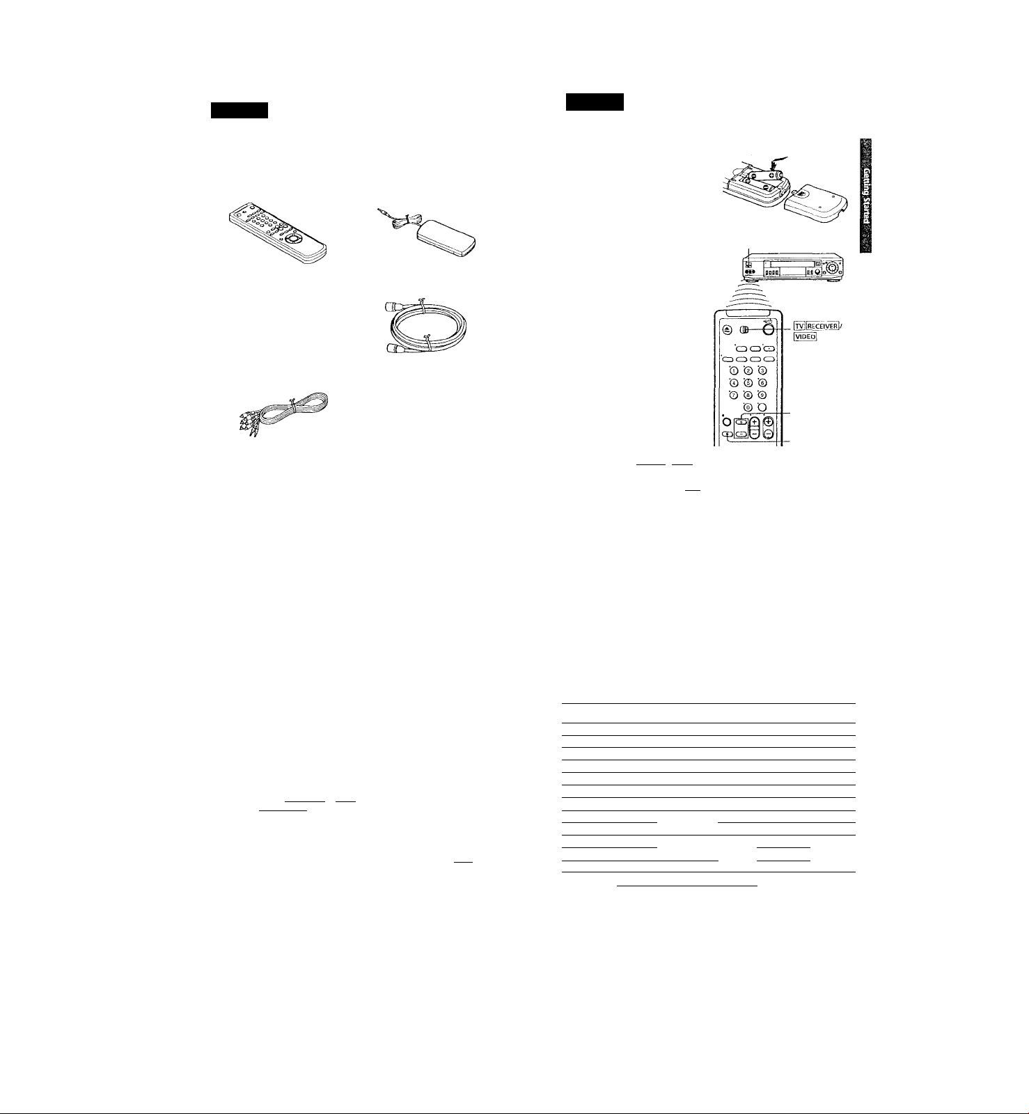
Step 1
Unpacking
Chect that you have received the following iteiris with the VCR:
• Rentote commander • Cable Mouse (cable box controller)
* Siz< AA (R6) batteries
’ Audio/video cable (3-phono, 1-mini
to 3-phono, 1-mini)
■ 75-ohm coaxial cable with F-type
connectors
Step 2
Setting up the remote commander
Inserting the batteries
Insert two size AA (R6) batteries
by nratching the + and — on the
batteries to the diagram inside the
battery compartment.
Insert the negative (-) end first,
then push in and down until the
positive (-♦-) end dicks into position.
Using the remote commander Remote sensor
You can use tliis remote
commander to operate this VCR
and a Sony TV or AV receiver.
Buttons on the remote
commander marked with a dot
(•) can be used to operate your
Sony TV.
The RECEIVER VOL +/- and
MUTING buttons can be used to
operate your Sony AV receiver.
RECEIVER VOL+/-
To operate Set [RECEIVErI <(VÍD'e6| to
a Sony TV
or aV receiver
and point at the remote sensor on the VCK
ITVIIRECEIVERI and point at Uie remote sensor on the TV or AV
receiver
4 j Gettini) Started
5fep 2; Setting up the remote commander (continued)
Notes
• With normal use, the batteries should last about three to six months.
• If you do not use the remote commander for an extended period of time, remove
the batteries to avoid possible damage from battery Icakage.
• LX) not use a new battery with an old one.
• Do not use different types of batteries.
• Some Sony AV receivers may not be operated with the remote commander.
Controlling other TVs with the remote commander
The remote commander is preprogrammed to control non-Sony TVs. If your
TV is listed in the table below, set the appropriate nuinufacturer's code
number.
Set rfVliRECEfVHRi/IVrDEOl at tlie top of the remote commander to
ItvIIrëœîverT
Hold down l/d), and enter your TV's code nuntber(s) using the number
buttons. Then release I/Ô.
Now you can use the 1/(1), VOL +/-, CH +/-, and TV/VIDEO buttons to
control your TV. You can also use the buttons marked with a dot {•) to
control a Sony TV. To control the VCR, reset ITv IfRECEIVE^ / IVIDE(5lto
LvidedJ -
Code numbers of controllable TVs
If more than one code number is listed, try entering them one at a time until
you find the one that works with your TV.
Manufacturer
Manufacturer
Sony
Akai
AOC 04
Centurion 12
Coronado 03
Curis-Mathes
Daytron
Emerson
Fisher
General Electric
Gold Star
Hitachi
J.C.I’cnny
Code
number
01 JVC 09
04 KMC
Magnavox
Marantz 04,13
MGA/Mitsubishi
12 NEC
12 Pataasonic 06,19
03,04,14 PhiJeo
11 Philips
Pioneer 16 Wards
06,10
Portland 03
03,04,17
02,03 Quasar
Radio Shac k 05,14
04,12
Notes
• If the TV uses a different remote coninil system from tlie one pn>grammeil to work
witli the VCR, you carmot control your TV witli the remote comirrander.
• If you enter a new code number, the code number previously entered will be erased.
• When you replace the batteries of the remote commander, the code numlx;r may
change. Set the appropriate code number every time you replace tlie batteries.
Manufacturer Code
Code
number
RCA
03 Sampo
03, 08,12 Sanyo
Scott
Sears
W,12,13,17
Sharp
04,12
Sylvania
Teknika 03, 08,14
03,04
Toshiba 07
08
Yorx 12
/.enith 15
Û6, 18
Getting Started | 5
number
04,10
12
11
12
07,10,11
03, 05,18
08,12
03, 04, 12
A
Hookups
Selecting the best hookup option
There arc many ways in which your V’CR can be hooked up. To hook up
your VCR so that it works best for you, first scan through the table below.
Tixen uso the accompanying diagrains and procedures on the following
pages to set up your VCR.
If you have
IV that has audio/video inputs
Cable box that is compatible with the
VCR's cable box control feature
No cable box or incompatible cable Ixix
with only a few scrambled channels
Antenna only, no cable TV
Incompatible cable box with many
scrambled channels
DiRbCrV* digital salcllile receiver
Incompatible cable box with only a few
scrambled channels, using an A/8
switch
After you've completed the connections, follow the instructions for setup.
During setup, if you need more details on the procedure described, page
mimbers are provided where you can find complete, step-by-step
instructions-
After you've completed the setup, you're ready to use your VCR.
Procedures differ depending on the hookup you used. For an overview,
refer to "Quick reference to using the VCR" on the back cover.
Before you get started
• Turn off the power to all equipment.
• Do not connect the AC power cords until all of the connections are
completed.
• De sure you make connectioius firmly. Ixaose cormcctions may cause
picture distortion.
• If your IV doesn’t match any of the examples provided, see your nearest
Sony dealer or qualified technician.
Audio/video (AAf) hookup, then Pages 9 and ti)
follow one of the hoiikups below.
Hookup 1
Hookup 2
Hookup 3
Hookup 5
Hookup 6
Pages 11 to 1<l
Pages 15 to Ifi
Pages 19 to 22
Pages 27 to 29
Pages 30 to 3!i
If your TV has audio/video (A/V) input jacks, you will get a better pichrre
and sound if you hook up your VCR using these connections. In addition,
for a tnie "home theater" experience, you should connect the audio outf'uts
of your VCR or TV to your stereo system. If your TV doesn't have A/V
inputs, sec the following pages for antenna or cable hookups.
If your TV has the S-Link’'*'" (A/V bus control) functum, hook up your VCR
using the connection shown on page 10. Your TV will automatically switch
to the A/V inputs for your VCR when you play back or operate menu on the
VCR.
If you're not plannii\g to use your VCR to record programs, you're finished
setting up the VCR after you've made the connections shown on pages 9 and
10. If you want to record off-air or off your cable TV system, complete these
connections first, and then go to the following pages for antenna or cable
hookups.
' Ls a trademark of Sony Corporation.
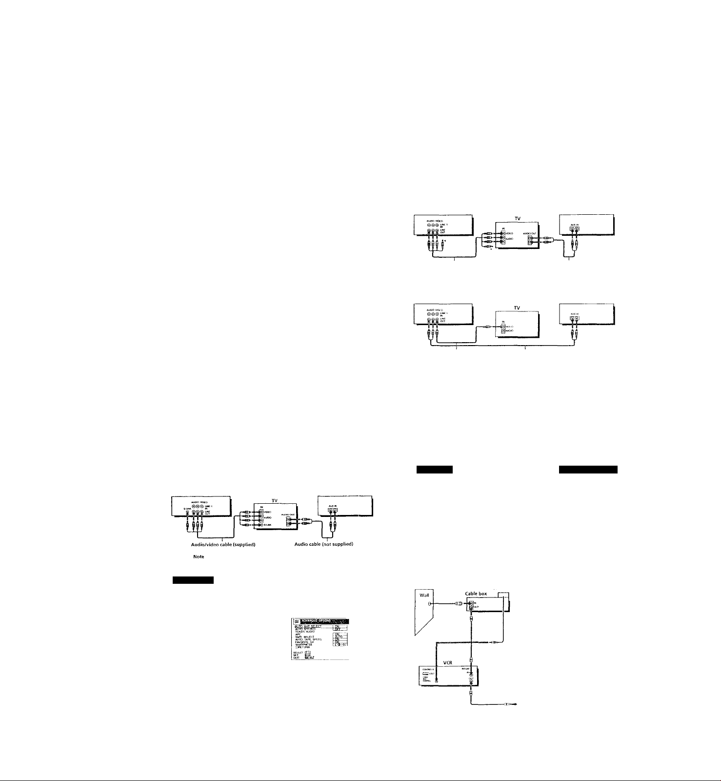
□ Use this hookup if your TV has stereo jacks
VCR
Audio/video cable (supplied) Audio cable (not supplied)
Stereo receiver
' Do not connect the miniplugs for this hookup.
m Use this hookup if your TV doesn't have stereo jacks
VCR Stereo receiver
Video cable (not supplied] Audio cable (not supplied)
• DlKl-X'l'V is a trademark of DIRhCTV', Inc.,.
, Getting Started
Step 3: Hookups (continued)
Use this hookup if your TV has the S-Link^“ function
VCR Stereo receiver
* To play a tape in stereo, you must use the A/V connection.
.AA/ hookup
Jh VCR setup
After you've connected your 'IV and completed antenna or cable hool.vipi,
use the following procedure to set up the VCR.
Press MENU and select
ADVANCED OPTIONS.
If of Hughes Electronics Coqioralio
Set AUTO ANT SELECT
to OFF and press OK.
Getting Started 1 9
Hookup" 'tPages 11 to 14
Using cable box control
Recommended use
You should use this hookup if you have a cable box, especially if your c able
system scrambles all or most channels. This htx)kup allows the VCR's cable
box control feature to control the channel on the cable box, simplifying the
recording process. A list of compatible cable boxes is on pages 47 to 49.
What you can do with this hookup
• Record any channel using the VCR's cable box control feature to select
channels on the cable box
What you can't do
• Record with the cable box turned off
• Record one channel wMfe watching another channel
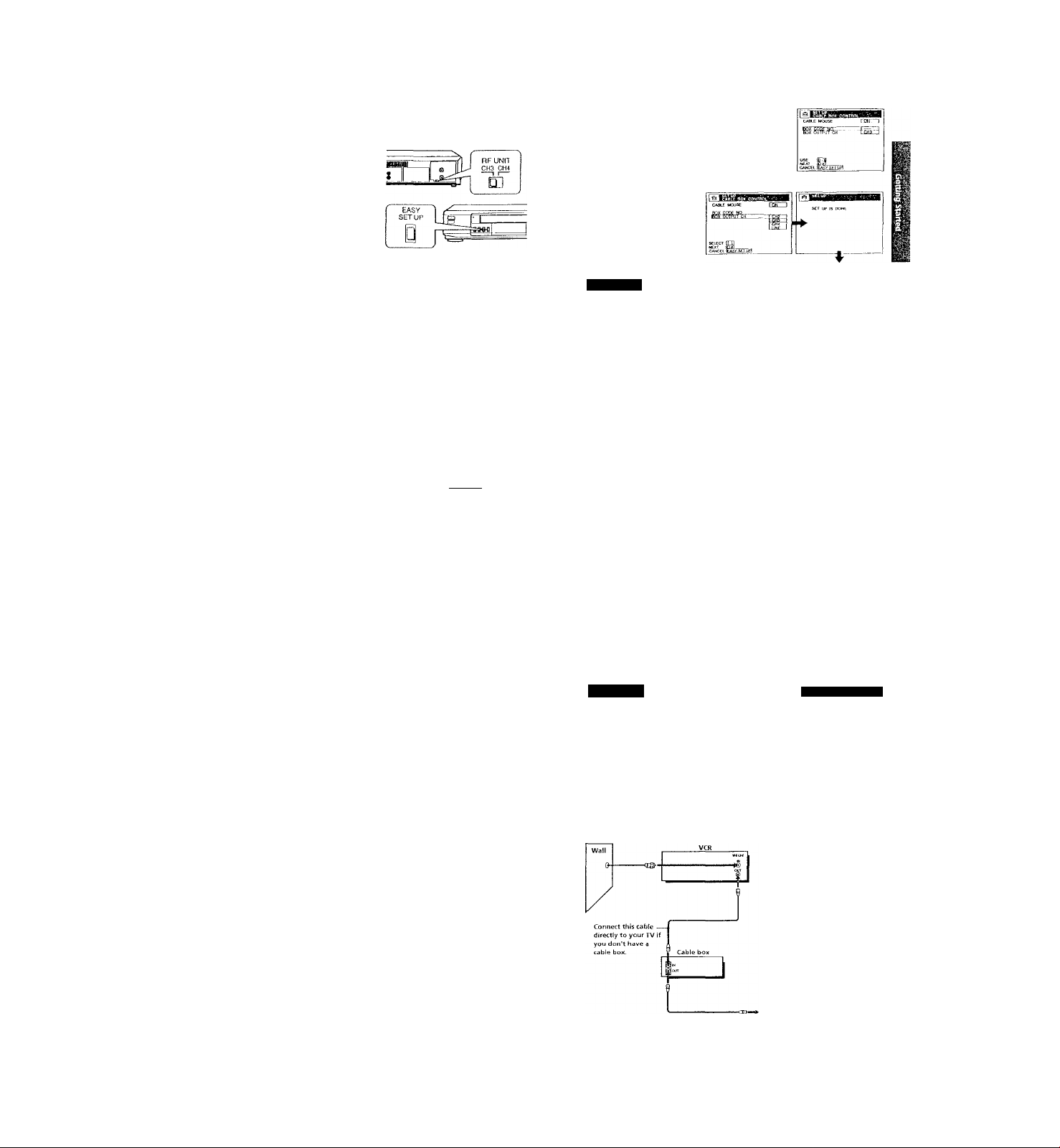
Cable Mouse
Rear of TV
VHF/UHF
-
----
@A
L®J
UHF
Match the type of
connector on your
TV; A, B, or C.
For connector types
B and C, no UHF
connection is
required.
Caution
For details, see page 100-
Connections between the VCR's VHF/UHT connector and the antenna teniiiniils o!
die TV receiver .should be made only assJiowji in the following inslriiclion.s, ] ailiin'
to do so may result in operation that violates the regulations of the Federal
Communications Commission regarding the use and operation of RF devices. Never
<xmnecl the output of the VCK to an antenna or make simullanwus (parallel) a nfonn.i
and VCR connections at the antenna tenninaLs of your receiver.
Note to CATV system installer (in USA)
ITis reminder Ls provided to call the CATV system iivstaller's attention to Arti< le H20
40 of the NEC that [irovides guidelines for proper grounding and, in parficulai,
s[)ecino,s that (he cable ground shall be connected to ll\e gniunding system of Ino
building, as close to the point of cable entry as practical.
Positioning the Cable Mouse
i’lacu the Cable Mouse so lh.it it
hangs out over the cable box
Side view
continued
с
f
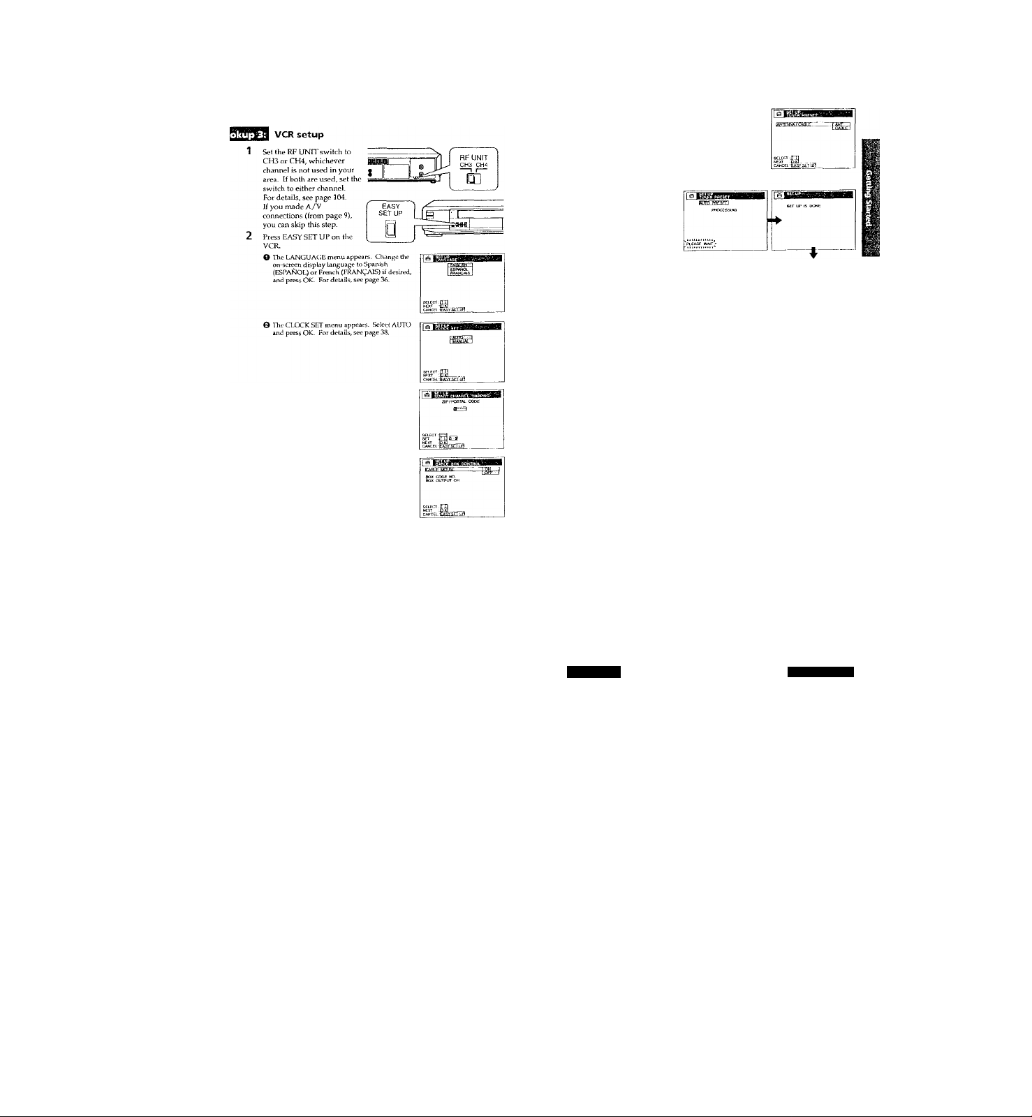
Step 3: Hookups (continued)
VCR setup
Set the RF UNIT switch to
CH3 or CH4, wiuchever
channel is not used in your
area. If both are used, set the
switch to either chaimel.
For details, see page 104.
If you made A/V
connections (from page 9),
you can skip tiris step.
Turn on your cable box.
I’ress EASY SET UP on ttie VCR.
O Tlie LANGUAGE menu appears. Change the
on-screen display language to Spanish
(ESPAÑOL) or French (FRANÇAIS) ii desired,
and press OK. Por details, see page 36.
0 The CLOCK SET menu appears. Select AUTO
and press OK. For details, see page 38.
© Tl-ic SMART CHANNEL MAPPING menu
appears. Press to enter the ZIP/
POSTAT.CODE in your area and press OK. (You
can also use Uie nun^er buttons to enter the
ZIP/l'OSTALCODE.)
О The CABLE 1ЮХ CONTROL menu appe.irs.
Select ON. For details, schí page 46.
ìl’^T
CABif Mouse
© Enter your cable box code number and press
OK. For details, see page 46.
O Select your cable box output channel and press OK.
Normal display
HopkuprI:
The VCR Plus+ GOLD system channel setup
1 Press MENU, then select SETTINGS and press
OK,
2 Select SET VCR Plus+ Cl 1ANNEI.S and press
OK.
3 Select AUTO and press OK.
--
X
.1
12 I Getting Started
Step 3: Hookups (continued)
The VCR receives the program information signal from 0:(Ю am to 5;(Ю am
while the VCR is turned off, and set up the channel for the VCR Plus+
GOLD system recording. After channel setup is finished, you can record TV
programs using tlie VCR Plus+ GOLD system. For details, see page 59.
Notes
• To use the Smart Channel Mapping feature, leave (he cable box on.
• It takes about 1 hour to complete channel setup.
• The VCR can receive the program information signal only while the VCR is turned
off and no timer recordings arc set.
• If the channels in your area don’t carry the program information signals, set the
program guide channels manually. For details, see page 62.
• If the CHOOSE YOUR CABLE CH MAP menu appears the first time you turn on
the VCR after finishing clLannel setup, select the MAP number. For details, sec
page 61.
Automatic clock setting
Once you've set up the VCR, it automatically sets the clock the first time you
turn off the VCR. After that, whenever you him off the VCR, it checks the
time and adjusts the clock, even for Daylight Saving Time. The VCR sets the
clock by picking up a time signal provided by some TV channels.
If you want to use the timer to record right away, or if the charmels in уош'
area do not carry time signals, sc‘t the clock manually. For details, see
page 41.
Note
• lb use the Auto Clock Set feature, leave the cable box on.
4 Press !/(!) to turn off the VCR.
,Hookup 2
No cable box, or incompatible cable box with only a
few scrambled channels
Recommended use
Use this hookup if you do not have a cable box. Also u-se this hookup if your
cable company cannot supply a cable box that is compatible with the VCR's
cable box control feature, and your cable system scrambles only a few
channels.
What you can do with this hookup
• Record any unscrambled clianne! by selecting the channel on the VCR
What you can't do
• Record scrambled cliannels that require a cable box
Rear of TV
VHF/UHE
‘ Pages 15'to t8
Match the type
■—gx
of connector on
your TV: A B. or
C.
For connector
types B and C,
no UHF
connection is
required.
c,
step 3: Hookups (continued)
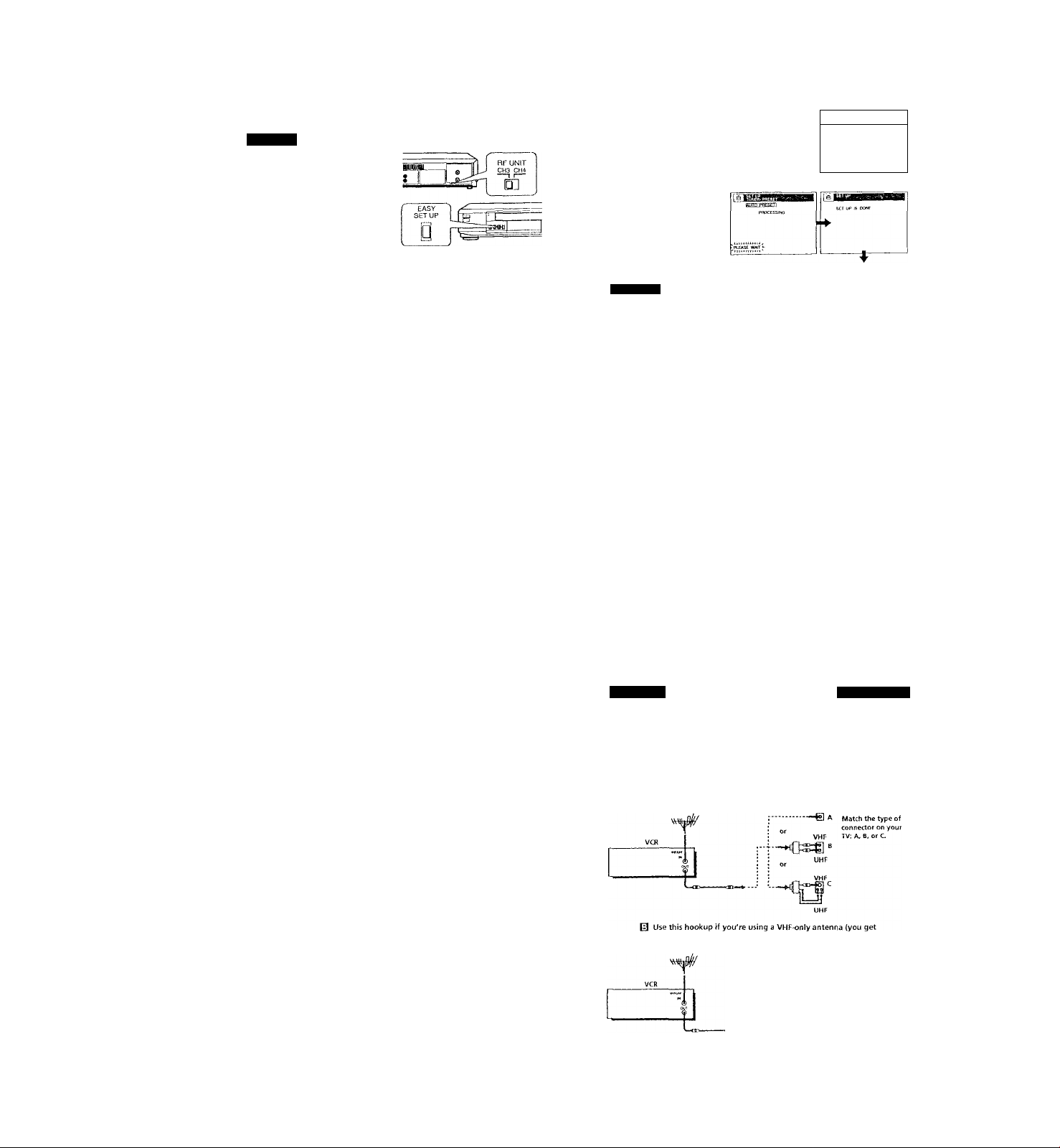
Hpokup¿
H VCR setup
1 Set the RF UNIT switd> to
CH3 or CH4, whichever
channel is not used in your
area. If both are used, set
the switch to either channel.
For details, see page 104.
If you made А/V
connections (from page 9),
you can skip this step.
2 Press EASY SET UP on
the VCRO The LANGUAGE menu appears. Change the
on-screcn display language lu Spanish
(ESPAÑOL) or French (HtANgALS) if desired,
and press OK. For details, see page 36.
O The CIOCK SET menu appears. Select AUTO
and press OK. For details, see page ,38.
© The SMART CHANNEL Mapping menu
appears. Press to enter the ZliV
POSTAL CODE in your area and press OK. (Yoi
can also use Ute number buttons to enter the
ДР/POSTALCODE.)
O The CABLE BOX CON TROL, menu appears.
5k?lcct OIT and press OK.
SrrjJH
0 The TUNER PRESET menu appears. Set
ANTENNA/CABLE to CABIE and press OK.
For details, sec page 52.
О Tire AUTO PRESET starts.
: Hookup 2
I The VCR Plus+ GOLD system channel setup
1 Press MENU, then select SETTINGS and press
OK.
2 Select SET VCR Plus+ CHANNELS and press
OK.
3 Select AUTO and press OK.
4 Prc.ss l/Ci) to turn off the VCR.
швшшяваши
StLECri .[ПП
'^г-гЛИ
Normal display
\Ш1
1 f ■ I Getting Started
Step 3: Hookups (continued)
The VCR receives the program infonnation sigr\al from 0;00 am to 5:00 :im
while the VCR is turned off, and set up the channel for the VCR Plus+
GOLD system recording. After channel setup is finished, you can record TV
progranis using the VCR Plus+ GOl.D system. For details, sec page ,39.
Notes
• It takes about 1 hour to complete charrnel setup.
• The VCR can receive the prograin information signal only while the VCR is turned
off and no liinor recordings are set.
• Jf Uie channels in your area don't carry the program information signals, set tlie
program guide channels manually. For details, see page 62.
• If the CHCXl'tSE YOUK CABLE CH MAP menu appears the first time you turn on
the VCR after finishing channel setup, select the MAP number. For details, see
page 61.
Automatic clock setting
Once you've set up the VCR, it automatically sets the clock the first time you
turn off the VCR. After that, whenever you turn off tire VCR, it checks the
time and adjusts the clock, even for Daylight Saving Time. The VCR sets the
clock by picking up a time signal provided by some TV channels.
If you want to use the timer to record right away, or if the channels in yovr
area do not carry time signals, set the clock manually. For details, see
page 43.
Getting Started I 17
Hobkup 3 rPagefr19:to'22 ^
Antenna hookup
Make the following connections if you're using an antenna (if you don'l
have cable TV).
□ Use this hookup if you're using;
• VHF/UHF antenna (you get channels 2-13 and channels 14 and higher)
• UHF-only antenna (you get channels 14 and higher)
• Separate VHF and UHF antennas
Rear of TV
VHF/UHF
channels 2-13 only)
If you cannot connect your antenna cable to the VCR directly
If your antenna cable is a fiat cable (,300-ohm twin lead cable), attach an external
anteniaa connector (not supplied) so you can connect the cable to tl\o VHIVUHi- IN
connector. If you have separate cables for VHi- and UHF antennas, you should use a
U/V band mixer (not supplied) For details, see page ¡05
Rear of TV
VHF/UHF Match the type of
■—e A connector on your
TV; A B, or C.
VHF
For connector types
--t] “
B and C no UHF
UHF
connection is
required.
VHF
—
UHF
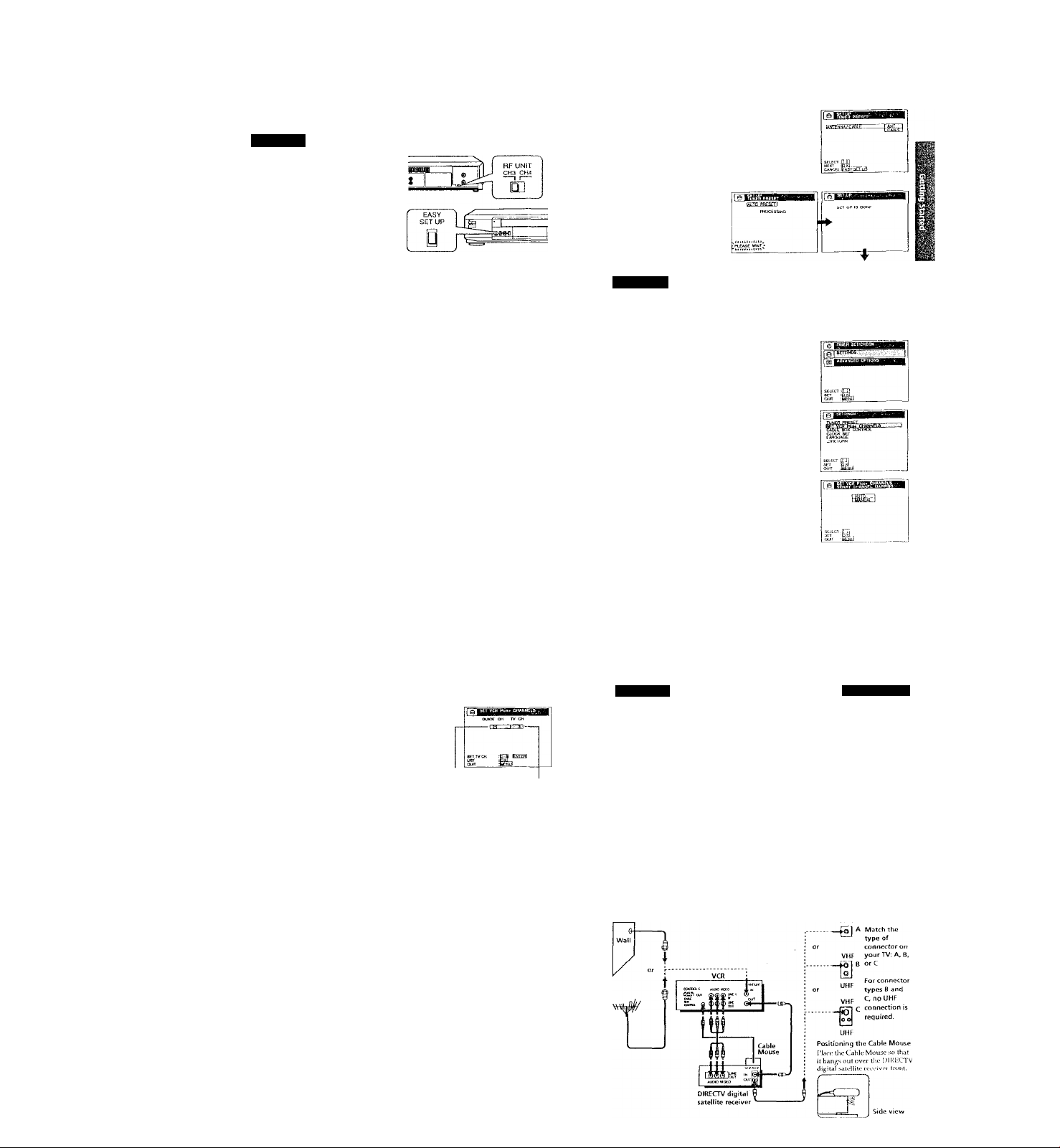
step 3: Hookups (continued)
0 The TUNER PRIiSET menu appears Set
ANPENNA/CABLE (o ANT and press OK. For
detaUs, sec page 52.
Ш
t
G Tlie AUTO PRESIH' starts.
Normal display
и^ИЕЕЯ Plus+ GOLD system channel setup
1 Press MENU, then select SETTINGS and press (^j|
OK.
2 5ieiect SET VCR Plus t- CHANNELS and press
O The SMART O lANMEL MAPPING menu
appears. Press f/♦/♦"/•♦ to enter the ZIP/
POSTAL CODE in your area and press OK. (You
can also use the number buttorcs to enter the
r
ZrP/POSTAl.CODE.)
О The CABLE ЮХСОКТКО! i
Select OPF and press OK.
OK.
3 Select AUTO and press OK.
■’Ё,
4 Press l/(!) to turn off the VCR.
e;(
201 Getting Started
sup 3: Hookups (continued)
The VCR receives the program information signal from 0:(X) am to 5;00 am
while the VCR is turned off, and set up the channel for the VCR Plus+
GOLD system recording. After channel setup is finished, you can record TV
programs using the VCR Plus+ GOLD system. For details, see page 59.
Notes
• U lakes about 1 hour to complete channel setup.
• The VCR can receive the program information signal only while the VCR is turned
off and no timer recordings are set.
• If die channels in your area don't carry tiie program information signals, set the
program guide channels manually. For details, see page 62.
• If the CHOOSE YOUR CABLE CH MAlP menu appears the first time you turn on
the VCR after finishing channel setup, select die MAP number. For details, see
page 61.
Automatic clock setting
Once you've set up the VCR, it aulomaticalJy sets the clock the first time you
turn off the VCR. After that, whenever you turn off the VCR, it checks the
time and adjusts the clcxrk, even for Daylight Saving Tune. The VCR sets the
clock by picking up a time signal provided by some TV channels.
If you want to use the timer to record right away, or if the charmels in your
area do not carry time signals, set the cltKk manually. For details, see
page 43.
Hookup 4
Incompatible cable box with many scrambled
channels
Recommended use
Use this hookup if your cable company cannot supply a cable box that is
compatible with the VCR's cable box control feature, and your cable system
scrambles all or most channels.
What you can do with this hookup
• Record any channel by selecting the channel on the cable box
What you can't do
• Record with the cable box timned off
• Record one channel while watching another channel
Rear ofTV
VHF/UHF
--
VHF
[Oj
UHF
Getting Started j 21
Page«!2'?.tp26:
Match the type of
connector on your
TV: A, B, or C.
For connector
types B and C. no
UHF connection
is required.
-cm—»- —
step 3: Hookups (continued)
Hookup 4; VCR setup
1 Set the RF UNIT switch to
CH3 or CH4, whichever
channel is not used in your
area. If both are used, set the
switch to either channelFor details, see page 104.
If you made A/V
connections (from page 9),
you can skip this step.
Turn on your cable boxPress EASY SET UP on the VCR.
O The LANGUAGE menu appears. Change the
on-screen display language to Spanish
(ESPAÑOL) or French (FRANÇAIS) if desired,
and press OK. For details, sec page 36.
^ The CLOCK SET menu app>ears. Select
MANUAL and press OK. Then set the clock
manually and press OK. For details, sec
page 44.
Hookup 4
0 The TUNER PRESET menu appears. Set
ANTENNA/CABLE to ANT and press OK. For
detaUs, see page 52.
Ô The AUTO PRESET starts.
Normal display
I The VCR Plus+ GOLD system channel setup
Find the VCR Plus+ GOLD system Chaimd Listing in your program
guide. For details, see page 58.
Enter all the channels you want to record and the cable box output
channel (usually 2, 3, or 4). For details, see page 62.
O Press MENU, tlien select SETTINGS and press
OK.
241 Getting Started
Step 3: Hookups (continued)
Automatic dock setting
To use the Auto Clock Set feature with this hookup, you need to manually
select a channel that carries a time signal:
1 Tune the cable box to a channel tl\at carries a time signal.
2 Select AUTO in the CLOCK SET menu to turn on the Auto Ckx:k Set
3 Turn off the VCR. It automatically sets the clock and adju.sts for
If you want to use the timer to record right away, or if the channeLs in your
area do not carry time signals, set the clock manually. For details, see
page 4.3.
Note
• To use tlic Auto CKx:k Set feature, leave the cable box on.
O The SMART CHANNEL MAPPING menu
appears- Press to enter the ZIP/
POSTAL CODE in your area and press OK. (You
can also use the number buttons to enter the
ZIP/POSTALCODE.)
O The CABLE BOX CONTROL menu appears.
Select OFF and press OK.
O Enter the program guide channel, then the cable
box output channel.
Program guide channel
0 Press OK.
© Press MENU to exit the menu.
feature.
Daylight Savmg Tune by picking up the time signal.
Cable box output chani
O Select SET VCR Flus+ CHANNEIS and press
OK.
0 Select MANUAL and press OK.
Hookup 5
DIRECTV digital satellite receiver
Recommended use
Use this hookup if you have a DIRECTV digital satellite receiver. It allows
the VCR's cable box control feature to control the cixannel on the DIREC/I'V
digital satellite receiver, simplifying the recording process. A list of
compatible DIRECTV digital satellite receivers is on page 49.
The DIRECTV System is a satellite broadcast that provides superior digitalquality video and crisp digital-quality audio. A variety of program packages
are available through your program providers. It also has program guides
that are sorted by program categories.
What you can do with this hookup
• Record any channels using the VCR's cable box control feature ti ^ '
channels on the DIRECTV digital satellite receiver.
What you can't do
• Record with the DUUiCTV digital satellite receiver turned off
• Record any charmels from cable or an antenna
(To record channels from cable or an antenna, turn off tlie cable box control
feature.)
• Use a cable box
• Record prograim witli the VCR Plus^-GOLD system ° ^
‘ ^ \ /Ur /1 ILir
Gettino i'.iited I 25
Pages 27,te.29
 Loading...