

Sony SLV-772HF, SLV-772HF3 Schematics
SLV-772HF/779HF
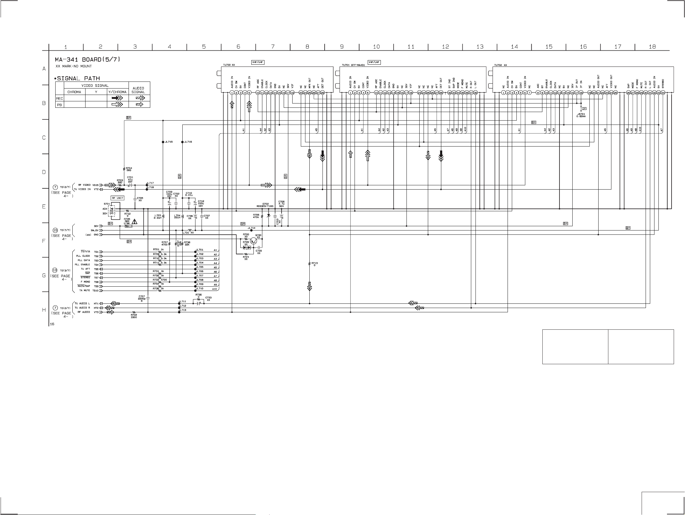
MA-341 (5/7) (TUNER) SCHEMATIC DIAGRAM
— Ref. No. MA-341 Board; 1,000 Series —
10
For schematic diagram
• Refer to page 4-5 for printed wiring board.
20
11
10
Note :
The components identified by
mark ! or dotted line with mark
! are critical for safety.
Replace only with part number
specified.
Note :
Les composants identifiés par
une marque ! sont cr itiques
pour la sécurité.
Ne les remplacer que par une
pièce portant le numéro spécifié.
4-15
4-16
TUNER
MA-341(5/7)
SLV-772HF/779HF
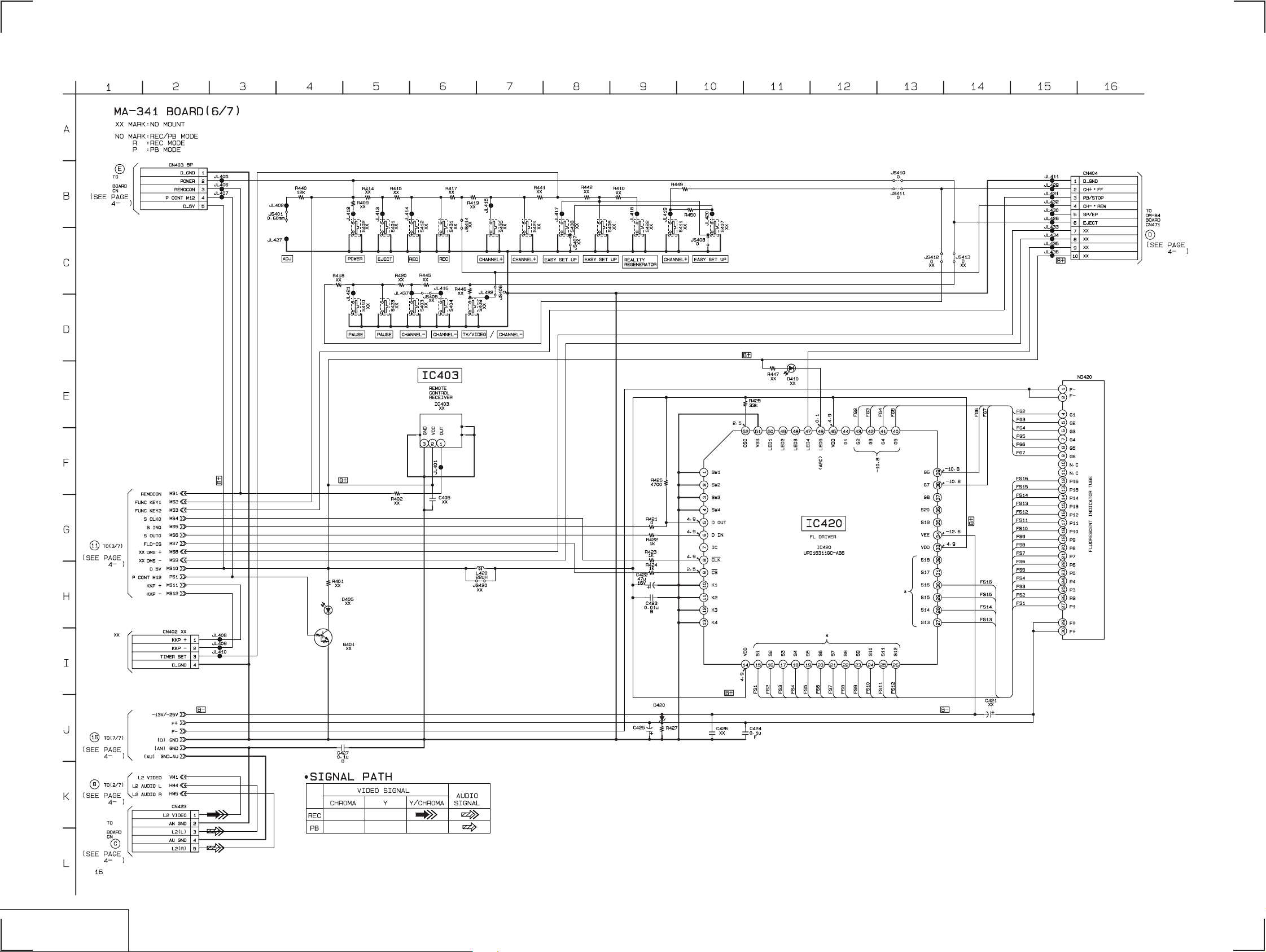
MA-341 (6/7) (MODE CONTROL) SCHEMATIC DIAGRAM
— Ref. No. MA-341 Board; 1,000 Series —
MF-316
461
23
For schematic diagram
• Refer to page 4-5 for printed wiring board.
6P
2.7k
27k
22
20
MF-316
491
23
11
RD5.6ES-T1B3
10
1.5k
50V
10
MODE CONTROL
MA-341(6/7)
4-17 4-18

SLV-772HF/779HF
MA-341 (7/7) (POWER SUPPLY) SCHEMATIC DIAGRAM
— Ref. No. MA-341 Board; 1,000 Series —
6.8M
DIA.5
For schematic diagram
• Refer to page 4-5 for printed wiring board.
1000p
0.033
AGC1A-V0
0.0022
120
200V
4.7
50V
100p
2SC4054P
MPG06D-6052PKG3
22 1/4W
15
13
15
8
11
120
620
0.0047
50V
AU02A-V0
0.47
1/4W
50V
56
47
50V
1uH
2.7
2W
0.01
470
1uH
10V
47
50V
Note :
The components identified by
mark ! or dotted line with mark
! are critical for safety.
Replace only with part number
specified.
Note :
Les composants identifiés par
une marque ! sont cr itiques
pour la sécurité.
Ne les remplacer que par une
pièce portant le numéro spécifié.
9
17
4-19 4-20
POWER SUPPLY
MA-341(7/7)

MF-316 (POWER/EJECT SWITCH) SCHEMATIC DIAGRAM
MA-341
VIDEO, AUDIO,
SERVO/SYSTEM CONTROL,
TUNER, POWER SUPPLY
MF-316
(POWER, EJECT SWITCH)
DM-84
(TAPE OPARATION)
— Ref. No. MF-316 Board; 2,000 Series —
LED DRIVER
IC461
REMOTE
CONTROL
RECEIVER
4-23 4-24E
 Loading...