

Sony MDS-SP55,CMT-SP55MD,CMT-SP55TC Service Manual
1
MDS-SP55
SPECIFICATIONS
SERVICE MANUAL
MINIDISC DECK
Model Name Using Similar Mechanism MDS-JE330
MD Mechanism Type MDM-5A
Optical Pick-up Type KMS-260B/S1NP
AEP Model
UK Model
E Model
System MiniDisc digital audio system
Laser Semiconductor laser (λ=780 nm)
Emission duration: continuous
Laser output Max. 44.6 µW*
*This output is the value
measured at a distance of 200 mm
from the objective lens surface on
the Optical Pick-up Block with
7 mm aperture.
Sampling frequency 44.1 kHz
Frequency response 20 Hz – 20 kHz
Inputs
DIGITAL OPTICAL CD IN: Optical
DIGITAL OPTICAL AUX IN: Optical
Output
DIGITAL OPTICAL OUT: Optical
General
Dimensions (w/h/d) incl. projecting parts and controls
Approx. 202 × 101 × 298 mm
Mass Approx. 1.7 kg
Supplied accessories System cable (1)
Digital cable (1)
Design and specifications are subject to change
without notice.
MDS-SP55 is the MD section in CMT -SP55MD ,
and MDS-SP55 is sold in the option as a
minidisk deck of CMT-SP55TC.
Ver 1.1 2001. 06
9-929-537-12
2001F0200-1
© 2001.6
Sony Corporation
Home Audio Company
Shinagawa Tec Service Manual Production Group
2
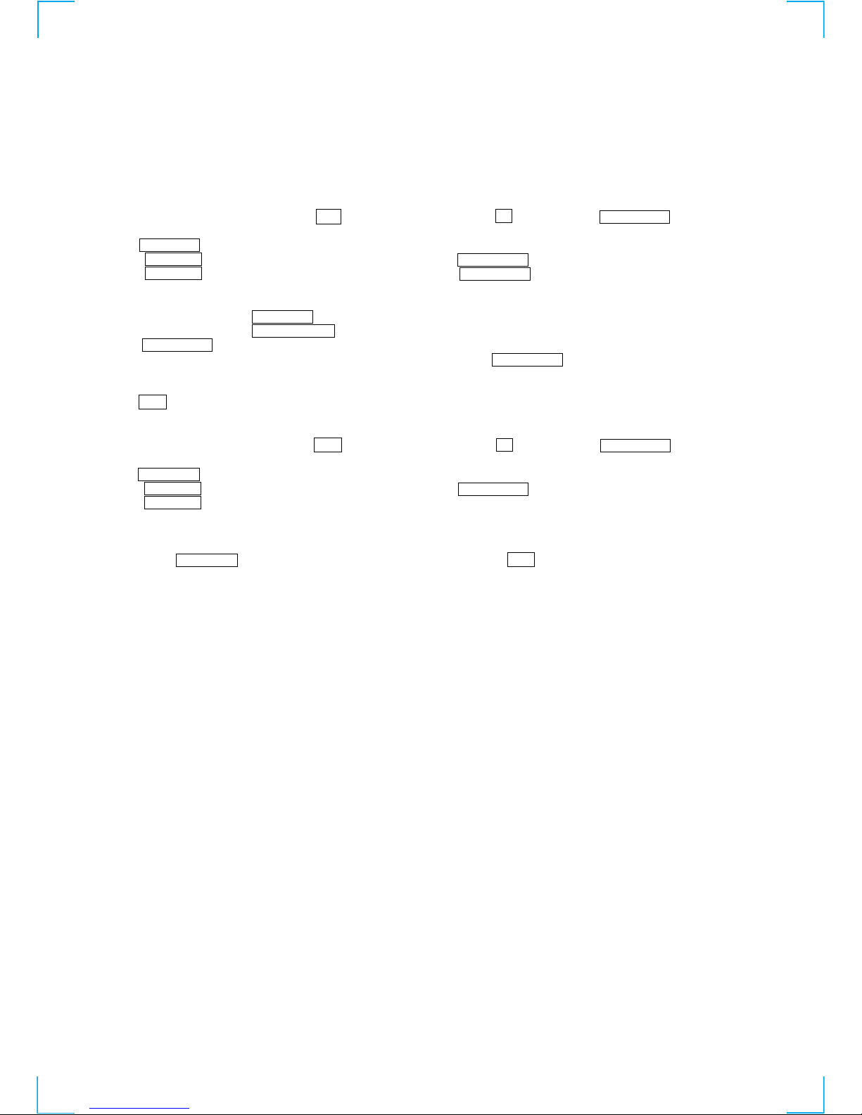
SELF-DIAGNOSIS FUNCTION
The self-diagnosis function consists of error codes for customers which are displayed automatically when errors occur, and error codes which
show the error history in the test mode during servicing. For details on how to view error codes for the customer, refer to the following box
in the instruction manual. For details on how to check error codes during servicing, refer to the following “Procedure for using the SelfDiagnosis Function (Error History Display Mode)”.
Procedure for using the Self-Diagnosis Function (Error History Display Mode).
Note: Perform the self-diagnosis function in the “error history display mode” in the test mode. The following describes the least required
procedure. Be careful not to enter other modes by mistake. If you set other modes accidentally, press the MENU/NO button (MD)
to exit the mode.
1. When the power OFF (STANDBY), press the ?/1 button (TA) while pressing the s button (MD) and ENTER/YES button (MD)
together.
2. Press the MENU/NO button, and when “Check” is displayed.
3. Rotate the l L knob (MD) and when “[Service]” is displayed, press the ENTER/YES button (MD).
4. Rotate the l L knob (MD) and display “ERR DP MODE”.
5. Pressing the ENTER/YES button (MD) sets the error history mode and displays “total rec”.
6. Select the contents to be displayed or executed using the l L knob (MD).
7. Pressing the CD SYNC REC button (MD) and to execute the contents selected.
8. Pressing the CD SYNC REC button (MD) another time returns to step 5.
9. Pressing the MENU/NO button (MD) displays “ERROR DP MODE” and exits the error history mode.
10.To exit the test mode, press the ?/1 button (TA). The unit sets into the STANDBY state, the disc is ejected, and the test mode ends.
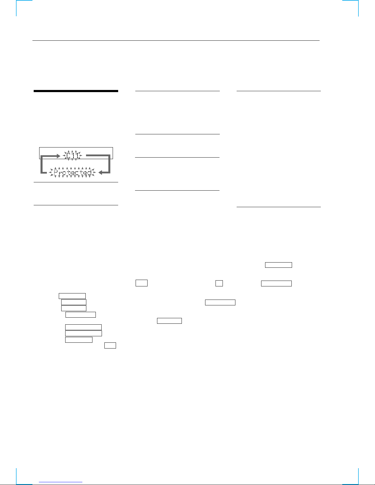
Self-diagnosis Display
This system has a Self-diagnosis display function
to let you know if there is a system malfunction.
The display shows a code made up of three letters
and a message alternately to show you the
problem. To solve the problem refer to the
following list. If any problem persists, consult
your nearest Sony dealer.
C11/Protected
The MD is protected against erasure.
cRemove the MD and slide the tab to close the
slot (See page 11).
C12/Cannot Copy
You tried to record a CD or MD with a format
that the system does not support, such as a CDROM.
cRemove the disc and turn off the system once,
then turn it on a
g
ain.
C13/REC Error
Recording could not be performed properly.
cMove the system to a stable place, and start
recording over from the beginning.
The MD is dirty or scratched, or the MD does
not meet the standards.
cReplace the MD and start recording over from
the beginning.
C13/Read Error
The MD deck cannot read the disc information
properly.
cRemove the MD once, then insert it again.
C14/Toc Error
The MD deck cannot read the disc information
properly.
cReplace the MD.
cErase all the recorded contents of the MD
using the All Erase function (See page 32).
C41/Cannot Copy
The sound source is a copy of a commercially
available music software, or you tried to record
a CD-R (Recordable CD).
cThe Serial Copy Management System
prevents making a digital copy .
You cannot record a CD-R (see page 43).
C71/Check OPT-IN
This appears momentarily because of the signal
of the digital broadcast during recording.
cThere is no affect on the recorded contents.
No component is connected to the DIGITAL
OPTICAL IN jack, or a digital component is
not connected properly.
cConnect a digital component to the DIGITAL
OPTICAL IN jack properly using a digital
connecting cable (an optical cable) (not
supplied (See page 39).
The connected digital component is not turned
on.
cSee the operating instructions supplied with
the connected component and confirm
whether the component is turned on.
The digital connecting cable (an optical cable)
connected to the DIGITAL OPTICAL IN jack
is pulled out, or the connected digital
component is turned off during digital
recording.
cConnect the cable, or turn on the digital
component.
3
Displays the recording time.
Displayed as “rssssssh”.
The displayed time is the total time the laser is set to the high power state.
This is about 1/4 of the actual recording time.
The time is displayed in decimal digits from 0h to 65535h.
Displays the play time.
Displayed as “pssssssh”. The time displayed is the total actual play time. Pauses are not counted.
The time is displayed in decimal digits from 0h to 65535h.
Displays the total number of retries during recording and number of retry errors during play.
Displayed as “rss pss”.
“r” indicates the retries during recording while “p” indicates the retry errors during play.
The number of retries and retry errors are displayed in hexadecimal digits from 00 to FF.
Displays the total number of errors.
Displayed as “total ss”.
The number of errors is displayed in hexadecimal digits from 00 to FF.
Displays the 10 latest errors.
Displayed as “0s E@@”.
s indicates the history number. The smaller the number, the more recent is the error. (00 is the latest).
@@ indicates the error code.
Refer to the following table for the details. The error history can be switched by rotating the l L knob (MD).
Mode which erases the “retry err”, “total err”, and “err history” histories.
When returning the unit to the customer after completing repairs, perform this to erase the past error history,
After pressing the CD SYNC REC button (MD) when “er refresh” appears, press ENTER/YES button (MD) to
erase the history.
“Complete!!” will be displayed momentarily.
Be sure to check the following when this mode has been executed.
• The data has been erased.
• The mechanism operates normally when recording and play are performed.
Mode which erases the “total rec” and “total play” histories.
These histories serve as approximate indications of when to replace the optical pick-up.
If the optical pick-up has been replaced, perform this operation and erase the history.
After pressing the CD SYNC REC button (MD) when “tm refresh?” is displayed, press the ENTER/YES button
(MD) to erase the history.
“Complete!” will be displayed momentarily.
Be sure to check the following when this mode has been executed.
• The data has been erased.
• The mechanism operates normally when recording and play are performed.
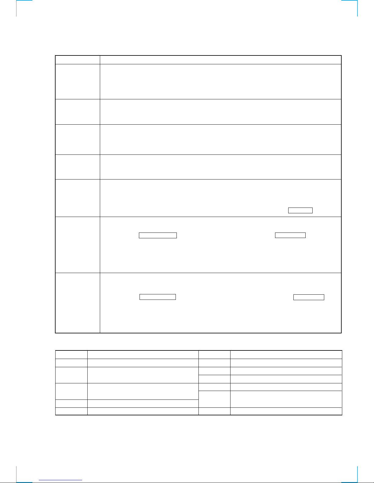
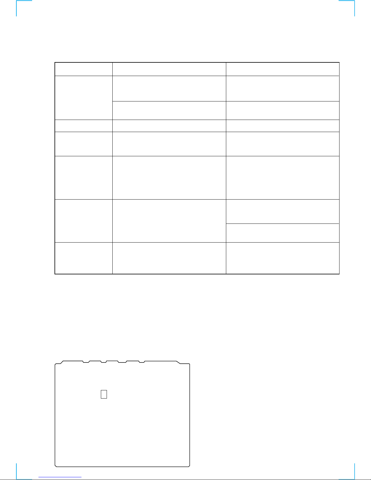
ITEMS OF ERROR HISTORY MODE ITEMS AND CONTENTS
Selecting the Test Mode
Display
total rec
total play
retry err
total err
err history
er refresh
tm refresh?
Details of History
No error
Read error. PTOC cannot be read
(DISC ejected)
TOC error. UTOC error
(DISC not ejected)
Loading error
Address cannot be read (Servo has deviated)
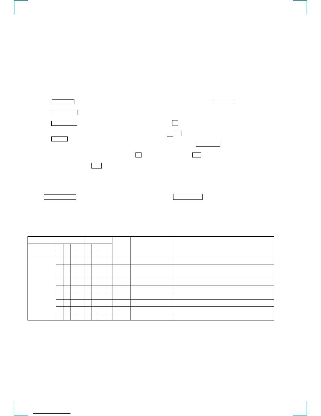
Table of Error Codes
Error Code
E00
E01
E02
E03
E04
E05
E06
E07
E08
E09
E0A
FOK has deviated
Cannot focus (Servo has deviated)
Recording retry
Recording retry error
Playback retry error
(Access error)
Play retry error (C2 error)
Details of Error
Error Code
Details of Error
4
CAUTION
Use of controls or adjustments or performance of procedures
other than those specified herein may result in hazardous radiation exposure.
Notes on chip component replacement
• Never reuse a disconnected chip component.
• Notice that the minus side of a tantalum capacitor may be
damaged by heat.
Flexible Circuit Board Repairing
• Keep the temperature of soldering iron around 270˚C
during repairing.
• Do not touch the soldering iron on the same conductor of the
circuit board (within 3 times).
• Be careful not to apply force on the conductor when soldering
or unsoldering.
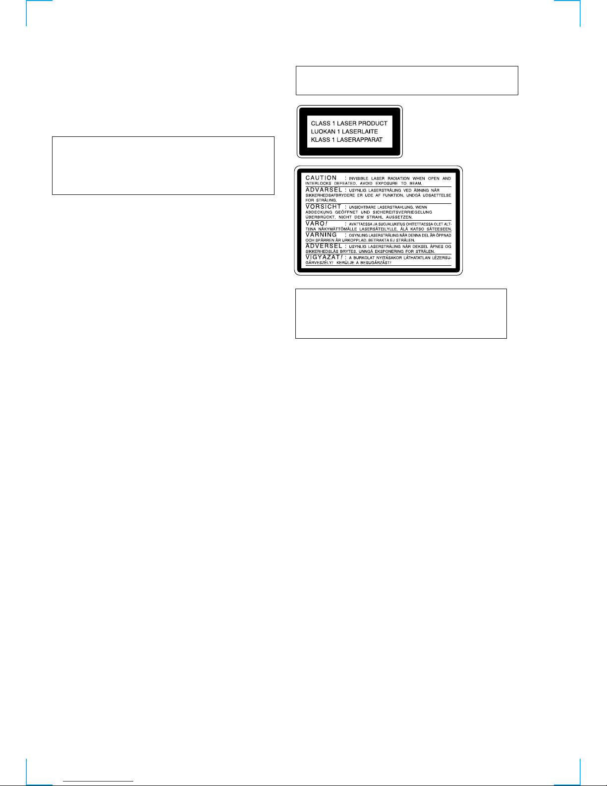
Laser component in this product is capable of emitting radiation
exceeding the limit for Class 1.
This appliance is classified as
a CLASS 1 LASER product.
The CLASS 1 LASER PRODUCT MARKING is located on
the rear exterior.
This caution
label is located
inside the unit.
CAUTION
Danger of explosion if battery is incorrectly replaced.
Replace only with the same or equivalent type recommended by
the equipment manufacturer.
Discard used batteries according to manufacture’s instructions.
ADVARSEL!
Lithiumbatteri - Eksplosionsfare ved fejlagtig håndtering.
Udskiftning må kun ske med batteri af samme fabrikat og type.
Levér det brugte batteri tilbage til leverandøren.
ADVARSEL
Eksplosjonsfare ved feilakting skifte av batteri.
Benytt samme batteritype eller en tilsvarende type anbefalt av
apparatfabrikanten.
Brukte batterier katterier kasseres i henhold til fabrikantens
VARNIG
Explosionsfara vid felaktigt batteribyte.
Använd samma batterityp eller en likvärdig typ som rekommenderas
av apparattillverkaren.
Kassera använt batteri enligt gällande föreakrifter.
VAROITUS
Parist voi räjähtää, jos se on virheellisesti asennettu.
Vaihda paristo ainoastaan laitevalmistajan suosittelemaan tyyppiin.
Hävitä käytetty paristo valmistajan ohjeiden mukaisesti.
SAFETY-RELATED COMPONENT WARNING !!
COMPONENTS IDENTIFIED BY MARK 0 OR DOTTED LINE
WITH MARK 0 ON THE SCHEMATIC DIAGRAMS AND IN
THE PARTS LIST ARE CRITICAL TO SAFE OPERATION.
REPLACE THESE COMPONENTS WITH SONY PARTS
WHOSE PART NUMBERS APPEAR AS SHOWN IN THIS
MANUAL OR IN SUPPLEMENTS PUBLISHED BY SONY.

5
TABLE OF CONTENTS
1. SERVICING NOTE .......................................................... 6
2. GENERAL ........................................................................ 13
3. DISASSEMBLY
3-1. Case ..................................................................................... 14
3-2. Front Panel Assy ................................................................. 14
3-3. MD Mechanism Deck (MDM-5A) ..................................... 15
3-4. Main Board ......................................................................... 15
3-5. Slider (Cam) ........................................................................ 16
3-6. BD Board ............................................................................ 16
3-7. Over Write Head ................................................................. 17
3-8. Optical Pick-up (KMS-260A/J1N) ..................................... 17
3-9. Spindle Motor, Sled Motor ................................................. 17
4. TEST MODE ..................................................................... 18
5. ELECTRICAL ADJUSTMENTS ............................... 22
6. DIAGRAMS
6-1. Block Diagrams
• BD Section ....................................................................... 32
• Main Section .................................................................... 33
6-2. Printed Wiring Board – BD Section – ................................. 34
6-3. Schematic Diagram – BD (1/2) Section – ........................... 35
6-4. Schematic Diagram – BD (2/2) Section – ........................... 36
6-5. Schematic Diagram – Main (1/2) Section – ........................ 37
6-6. Schematic Diagram – Main (2/2) Section – ........................ 38
6-7. Printed Wiring Board – Main Section – .............................. 39
6-8. Printed Wiring Board – Panel Section – ............................. 40
6-9. Schematic Diagram – Panel Section – ................................ 41
6-10. Schematic Diagram – BD Switch Section – .................... 42
6-11. Printed Wiring Board – BD Switch Section – .................. 42
6-12. IC Block Diagrams ........................................................... 42
6-13. IC Pin Functions ............................................................... 45
7. EXPLODED VIEWS
7-1. Case and Front Panel Section ............................................. 50
7-2. Mechanism Deck Section (MDM-5A) ................................ 51
7-3. Base Unit Section (MBU-5A) ............................................. 52
8. ELECTRICAL PARTS LIST ........................................ 53
MODEL IDENTIFICATION
— BACK PANEL —
• Abbreviation
AED : North European model
MY : Malaysia model
SP : Singapore model
HK : Hong kong model
KR : Korea model
MODEL
AEP, UK, AED models
HK, MY, SP models
KR model
PARTS No.
4-229-665-0s
4-229-665-2s
4-229-665-3s
Parts No.

6
SECTION 1
SERVICING NOTE
This unit cannot be repaired by itself.
When repairing, connect the whole system except for the speaker.
CD Text Display
• This unit displays CD text.
Text is displayed for the first 50 track only and will not be displayed from the 51st track onwards. Do not suspect a fault in this case.
In some cases, some special characters will not be displayed and may be replaced by other characters. Do not suspect a fault in this case.
Cold Reset
• The cold reset clears all data including preset data stored in the RAM to initial conditions. Execute this mode when returning the set to the
customer.
Procedure :
1. When the power ON, press the ?/1 button (TA) while pressing the TUNING MODE button (ST) and ML buttons (CD) together.
2. “COLD RESET” is displayed on the fluorescent indicator tube and reset is executed.
Hot Reset
• This mode reset the preset data kept in the memory. The hot reset mode functions same as if the power cord is plugged in and out.
Procedure :
1. When the power ON, press the ?/1 button (TA) while pressing the TUNING MODE button (ST) and lm buttons (CD) together.
2. Turn off the unit and reset is executed.
GC Test Mode
Procedure :
1. When the power ON, press the ?/1 button (TA) while pressing the TUNING MODE button (ST) and PLAY MODE buttons (CD)
together.
2. LCD are all turned on.
3. Press TUNING MODE button (ST) to enter the model destination indecation mode. “SP55 CE2” or “SP55 ASIA2” appears.
4. Every pressing of TUNING MODE button (ST) changes the display in the following order.
MC Version t CD Version t ST Version t TC Version t TA Version t TM Version t model destination display.
5. Press DISPLAY button (ST) and the date appears as “ 00615a ”
Every pressing of DISPLAY button (ST) changes the display in the Version display and model destination display.
6. Press TUNER/BAND button (ST) to enter the key check mode.
7. In the key check mode, the fluorescent indicator tube displays “Key 0 Vol 0”. Each time a button is pressed, “Key” value increases.
However, once a button is pressed, it is no longer taken into account.
“Vol” Value increases like “1, 2, 3 ...” if rotating VOLUME knob (TA) in the clockwise direction, or decreases like “0, 9, 8 ...” if rotating
in the counterclockwise diretion.
8. To exit from this mode, disconnect the power cord.

7
JIG FOR CHECKING BD BOARD WAVEFORM
The special jig (J-2501-149-A) is useful for checking the waveform of the BD board. The names of terminals and the checking items to be
performed are shown as follows.
GND : Ground
I+3V : For measuring IOP (Check the deterioration of the optical pick-up laser)
IOP : For measuring IOP (Check the deterioration of the optical pick-up laser)
TEO : TRK error signal (Traverse adjustment)
VC : Reference level for checking the signal
RF : RF signal (Check jitter)
RF
VC
TEO
For
MDM-3
For
MDM-5
A
IOP
I-3V
VC
RF
TEO
IOP
I+3V
GND
VC
RF
TEO
IOP
I+3V
GND
1
5
1
6
CN110
RF
5P connector
6P connecto
r
VC
TEO
IOP
I+3V
GND
Mechanism deck
8
IOP DATA RECORDING AND DISPLAY WHEN OPTICAL PICK-UP AND NON-VOLATILE MEMORY (IC171 OF
BD BOARD) ARE REPLACED
The IOP value labeled on the optical pick-up can be recorded in the non-volatile memory. By recording the value, it will eliminate the need
to look at the value on the label of the optical pick-up. When replacing the optical pick-up or non-volatile memory (IC171 of BD board),
record the IOP value on the optical pick-up according to the following procedure.
Record Precedure:
1. When the power OFF (STANDBY), press the ?/1 button (TA) while pressing the s button (MD) and ENTER/YES button (MD)
together.
2. Press the MENU/NO button (MD), and when “Check” is displayed.
3. Rotate the l L knob (MD) to display “MD [Service]”, and press the ENTER/YES button (MD).
4. Rotate the l L knob (MD) to display “MD lop Write”, and press the ENTER/YES button (MD).
5. The display becomes “MD Ref=@@@.@” (@ is an arbitrary number) and the numbers which can be changed will blink.
6. Input the IOP value written on the optical pick-up.
To select the number : Press the MENU/NO button (MD), and when “Check” is displayed.
To select the digit : Press the CD SYNC REC button (MD).
7. When the ENTER/YES button (MD) is pressed, the display becomes “MD Measu=@@@.@” (@ is an arbitrary number).
8. As the adjustment results are recorded for the 6 value. Leave it as it is and press the ENTER/YES button (MD).
9. “MD Complete!” will be displayed momentarily. The value will be recorded in the non-volatile memory and the display will become
“MD Iop Write”.
10. Press the ?/1 button (TA) to complete.
Display Precedure:
1. When the power OFF (STANDBY), press the ?/1 button (TA) while pressing the s button (MD) and ENTER/YES button (MD)
together.
2. Press the MENU/NO button (MD), and when “Check” is displayed.
3. Rotate the l L knob (MD) to display “MD [Service]”, and press the ENTER/YES button (MD).
4. Rotate the l L knob (MD) to display “MD lop Read”.
5. “MD @@.@/##.#” is displayed and the recorded contents are displayed.
@@.@ : indicates the Iop value labeled on the pick-up.
##.# : indicates the Iop value after adjustment
6. To end, press the MENU/NO button (MD) to display “MD Iop Read”. Then press the ?/1 button (TA).
9
• 0.9 mW power
Specified value : 0.84 to 0.92 mW
• 7.0 mW power
Specified value : 6.8 to 7.2 mW
lop (at 7mW)
• Labeled on the optical pick-up
Iop value ± 10mA
• Traverse waveform
Specified value : Below 10% offset
• Error rate check
Specified value : For points a, b, and c
C1 error : Below 220
AD error : Below 2
• Error rate check
Specified value:
a.When using test disc (MDW-74/GA-1)
C1 error : Below 80
AD error : Below 2
b.When using check disc (TDYS-1)
C1 error : Below 50
• CPLAY error rate check
Specified value:
C1 error : Below 80
AD error : Below 2
• Unsatisfactory if displayed as T=@@ (##) [NG]
NG
(@@, ## are both arbitrary numbers)
CHECKS PRIOR TO PARTS REPLACEMENT AND ADJUSTMENTS
Before performing repairs, perform the following checks to determine the faulty locations up to a certain extent.
Details of the procedures are described in “5 Electrical Adjustments”.
Laser power check
(5-6-2 : See page 24)
Traverse check
(5-6-3 : See page 24)
Focus bias check
(5-6-4 : See page 25)
C PLAY check
(5-6-5 : See page 25)
Self-recording/playback
check
(REC/PLAY)
(5-6-6 : See page 25)
TEMP check
(Temperature
compensation
offset check)
(5-6-1 : See page 24)
Criteria for Determination
(Unsatisfactory if specified value is not satisfied)
• Clean the optical pick-up
• Adjust again
• Replace the optical pick-up
• Replace the optical pick-up
• Replace the optical pick-up
• Replace the optical pick-up
• Replace the optical pick-up
If always unsatisfactory:
• Replace the overwrite head
• Check for disconnection of the circuits around the
overwrite head
If occasionally unsatisfactory:
• Check if the overwrite head is distorted
• Check the mechanism around the sled
• Check for disconnection of the circuits around D101
(BD board)
• Check the signals around IC101, IC121, CN102,
CN103 (BD board)
Measure if unsatisfactory:
Note:
The criteria for determination above is intended merely to determine if satisfactory or not, and does not serve as the specified value for
adjustments.
When performing adjustments, use the specified values for adjustments.
FORCED RESET
The system microprocessor can be reset in the following procedure.
Use these procedure when the unit cannot be operated normally due to the overrunning of the microprocessor, etc.
Procedure :
Remove the short-pin attached to CN821, and power off or del AC cable, and then attach it again. Remove the AC code, and wait for about
five seconds, and turn on the power again, and put the short-pin.
[MAIN BOARD] (Component Side)
CN821
10
RETRY CAUSE DISPLAY MODE
• In this test mode, the causes for retry of the unit during recording can be displayed on the fluorescent indicator tube. During playback, the
“track mode” for obtaining track information will be set.
This is useful for locating the faulty part of the unit.
• The following will be displayed :
During recording and stop : Retry cause, number of retries, and number of retry errors.
During playback : Information such as type of disc played, part played, copyright.
These are displayed in hexadecimal.
Procedure:
1. Load a recordable disc whose contents can be erased, into the unit.
2. Press the MENU/NO button (MD). When “Edit/Menu” is displayed on the LCD display, Rotate the l L knob (MD) to display
“All Erase??”.
3. Press the ENTER/YES button (MD).
4. “All Erase??” is displayed on the LCD display.
5. Press the ENTER/YES button (MD) to display “Complete!!”, and press the s button (MD) immediately. Wait for about 10 seconds
while pressing the button.
6. When the “MD Blank disk” displayed on the LCD display goes off, release the s button (MD).
7. Press the z REC button (MD) to enter recording standby. Then press the S button (MD) and start recording. In about 2 seconds, the
record mode retry cause is displayed. (Fig.1) If recording cannot be performed, rotate the FUNCTION konb (TA) and set a different
section.
8. To check the “track mode”, stop recording by pressing s button (MD) and press the H button (MD) to start play and the track
information in the play mode appears.
9. To exit the test mode, press the ?/1 button (TA), and turn OFF the power. When “STNDBY” disappears, disconnect the power plug
from the outlet. If the test mode cannot be exited, refer to “Forced Reset”on page 9.
} Address (Physical address on disc)
Hexadecimal
Bit
Binary
Higher Bits Lower Bits
84218421
b7 b6 b5 b4 b3 b2 b1 b0
00000001
00000010
00000100
00001000
00010000
00100000
01000000
10000000
When track jump (shock) is detected
When ADER was counted more than five times
continuously
When ADIP address is not continuous
When DIN unlock is detected
When not in focus
When ABCD signal level exceeds the specified range
When CLV is unlocked
When access operation is not performed normally
Hexa-
decimal
shock
ader5
Discontinuous address
DIN unlock
FCS incorrect
IVR rec error
CLV unlock
Access fault
Cause of Retry Occurring conditions
01
02
04
08
10
20
40
80
Fig. 1 Reading the Test Mode Display
(During recording and stop)
RTs@@c##c**
Fluorescent display tube display
@@ : Cause of retry
## : Number of retries
** : Number of retry errors
Fig. 2 Reading the Test Mode Display
(During playback)
@@####**$$
Fluorescent display tube display
@@ : Parts No. (name of area named on TOC)
## : Cluster
** : Sector
$$ : Track mode (Track information such as copyright
information of each part)
Reading the Display:
Convert the hexadecimal display into binary display. If more than two causes, they will be added.
Example
When 42 is displayed:
Higher bit : 4 = 0100 t b6
Lower bit : 2 = 0010 t b1
In this case, the retry cause is combined of “CLV unlock” and “ader5”.
When A2 is displayed:
Higher bit : A = 1010 t b7+b5
Lower bit : 2 = 0010 t b1
The retry cause in this case is combined of “Access fault”, “IVR rec error”, and “ader5”.
Reading the Retry Cause Display
11
Hexadecimal
Bit
Binary
Higher Bits Lower Bits
84218421
b7 b6 b5 b4 b3 b2 b1 b0
00000001
00000010
00000100
00001000
00010000
00100000
01000000
10000000
Hexa-
decimal
Details
01
02
04
08
10
20
40
80
Emphasis OFF
Monaural
This is 2-bit display. Normally 01.
01:Normal audio. Others:Invalid
Audio (Normal)
Original
Copyright
Write prohibited
When 0 When 1
Emphasis ON
Stereo
Invalid
Digital copy
No copyright
Write allowed
Reading the Display:
Convert the hexadecimal display into binary display. If more than two causes, they will be added.
Example When 84 is displayed:
Higher bit : 8 = 1000 t b7
Lower bit : 4 = 0100 t b2
In this case, as b2 and b7 are 1 and others are 0, it can be determined that the retry cause is combined of “Emphasis OFF”, “Monaural”,
“Original”, “Copyright exists”, and “Write allowed”.
Example When 07 is displayed:
Higher bit : 0 = 1000 t All 0
Lower bit : 7 = 0111 t b0+b1+b2
In this case, as b0, b1, and b2 are 1 and others are 0, it can be determined that the retry cause is combined of “Emphasis ON”, “Stereo”,
“Original”, “Copyright exists”, and “Write prohibited”.
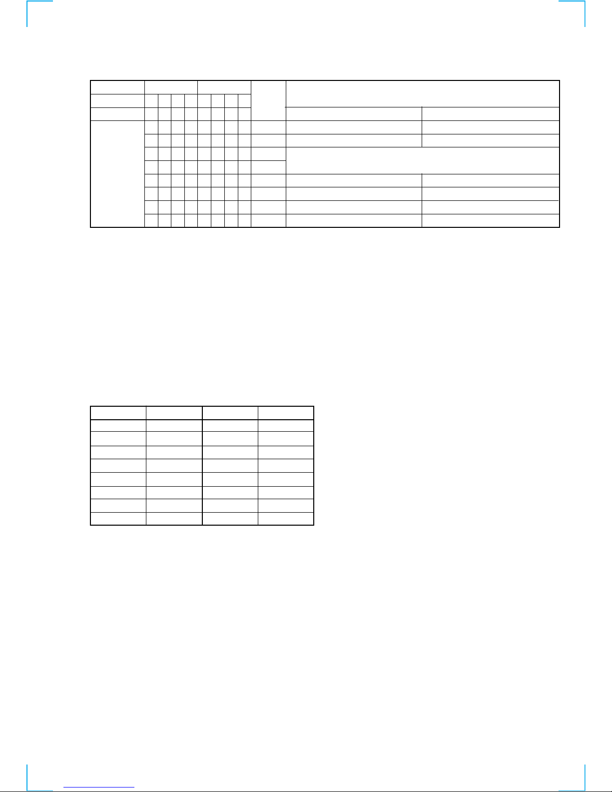
Hexadecimal t Binary Conversion Table
Hexadecimal Binary Hexadecimal Binary
0
1
2
3
4
5
6
7
8
9
A
B
C
D
E
F
0000
0001
0010
0011
0100
0101
0110
0111
1000
1001
1010
1011
1100
1101
1110
1111
Reading the Track Mode Display
12
SERVICING POSITION
1. Remove the four screws securing the upper case, and remove the upper case.
2. Remove the three screws A securing the rear panel.
3. Remove the two craws B securing the MAIN board.
4. Remove the MAIN board with the rear panel.
A
B
B
13
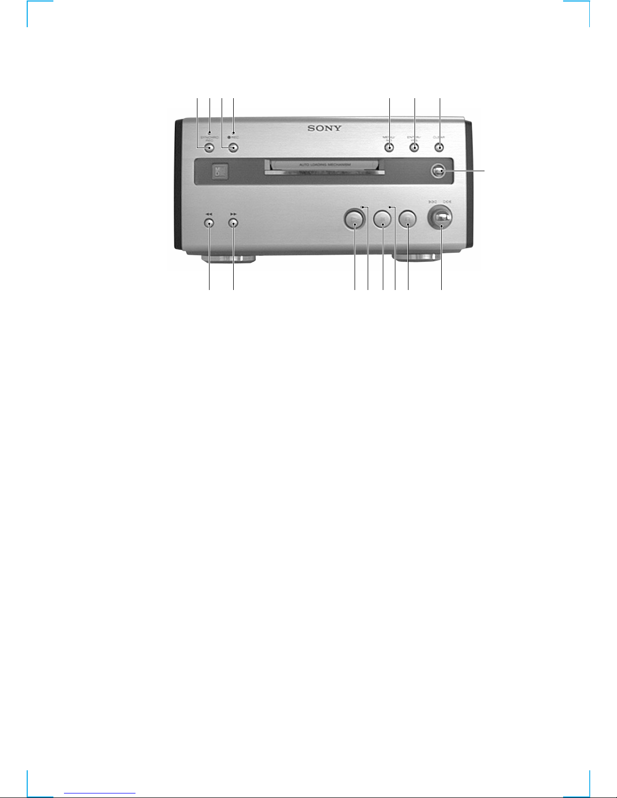
SECTION 2
GENERAL
1 CD SYNC REC button
2 CD SYNC REC indicator
3 z REC button
4 z REC indicator
5 MENU/NO button
6 ENTER/YES button
7 CLEAR button
8 A button
9 l L knob
q; s button
qa S indicator
qs S button
qd H insdicator
qf H button
qg M button
qh m button
1 42 5 6 7
8
90qsqf qaqgqh
3
qd
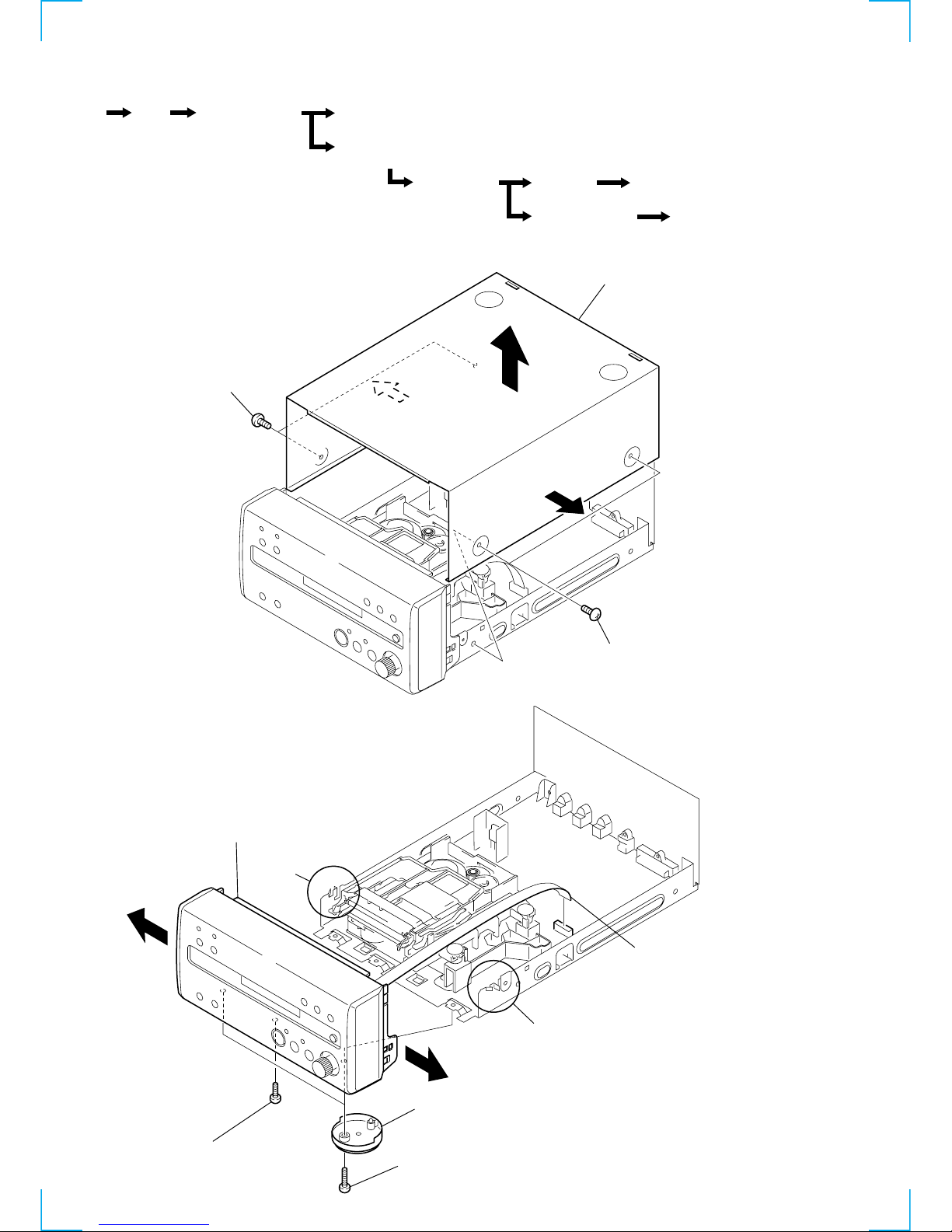
14
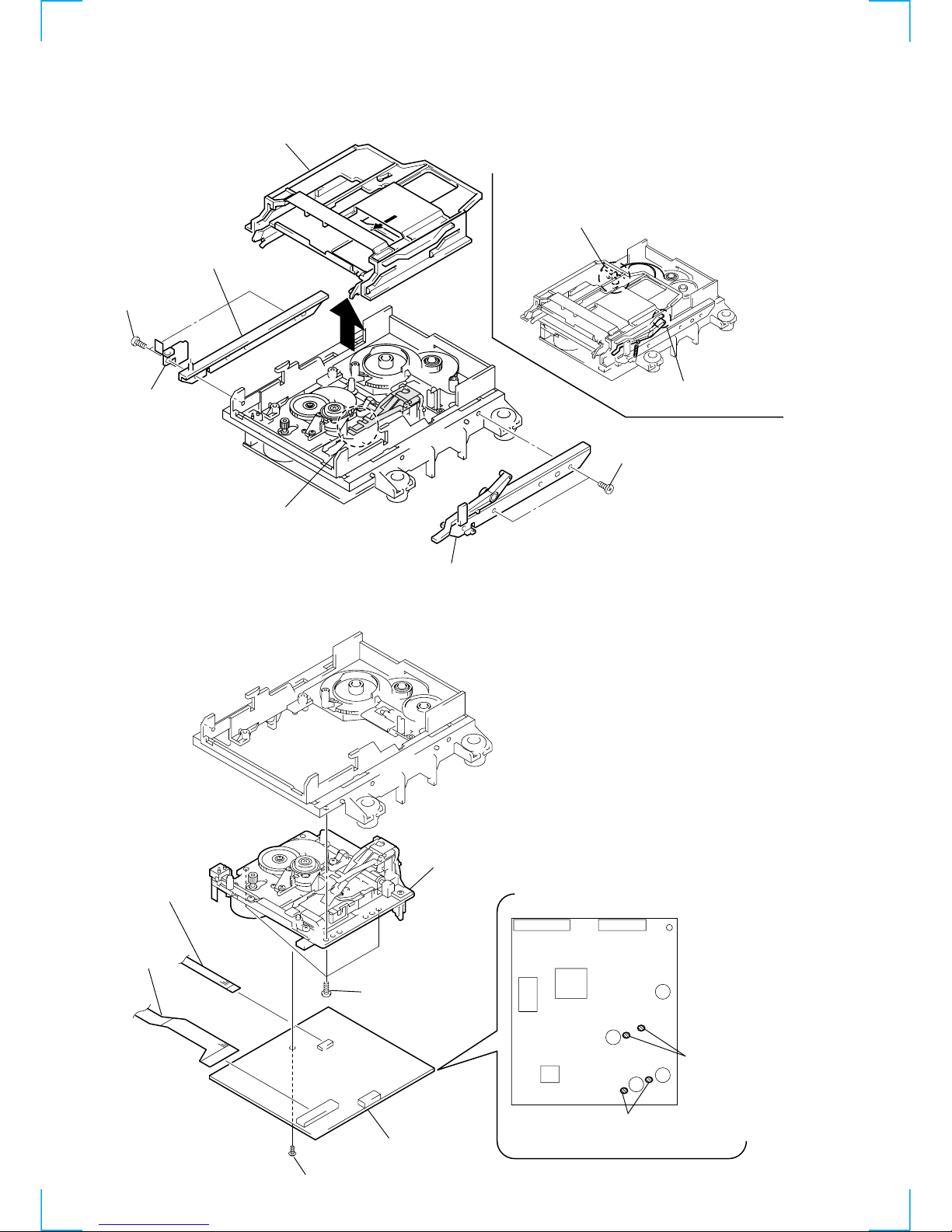
3-1. CASE
3-2. FRONT PANEL ASSY
Note: Follow the disassembly procedure in the numerical order given.
SECTION 3
DISASSEMBLY
1 two screws
(case 3 TP2)
4 case
1 two screws
(case 3 TP2)
2
2
3
1 flat type wire (11 core
)
(CN791)
4 screw (BVTP 3x12)
5 front panel assy
2 two screws
(BVTP 3x12)
3 two foot assy's
claws
claws
Set Case Front Panel Assy
MD Mechanism Deck (MDM-5A)
(Page 15)
Slider (Cam)
(Page 16)
BD Board
(page 16)
Spindle Motor, Sled Motor
(page 17)
Optical pick-up
(page 17)
Over Write Head
(Page17)
Main Board
(Page 15)
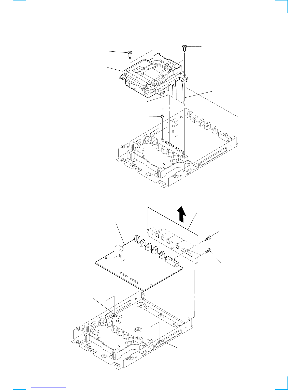
15
3-3. MD MECHANISM DECK
(MDM-5A)
3-4. MAIN BOARD
1 flat type wire (23 core)
(CN702)
2 flat type wire (21 core)
(CN501)
5 MD mechanism deck
3 connector
(CN701)
4 two screws
(BVTPWH M3)4 two screws
(BVTPWH M3)
2 three screw
s
(BVTP 3x8)
4 claw
4 claw
3 panel back
1 six screws
(BVTP 3x8)
5 main board
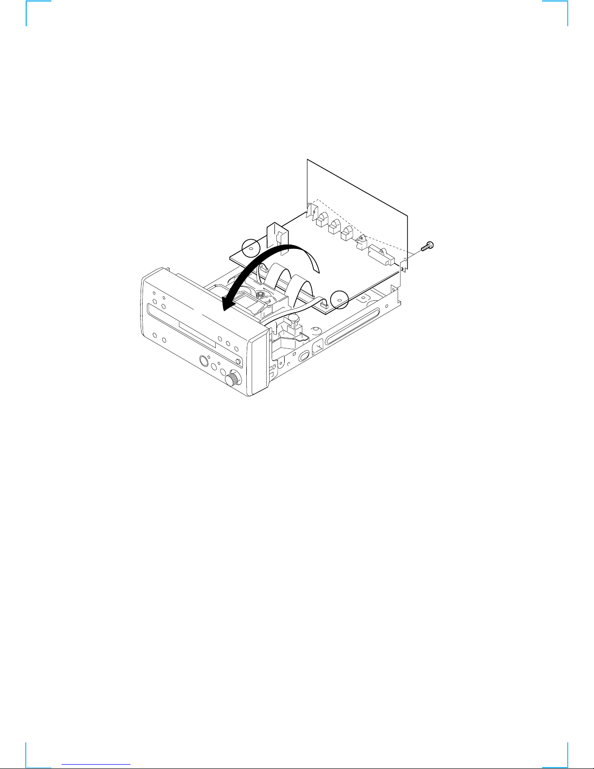
16
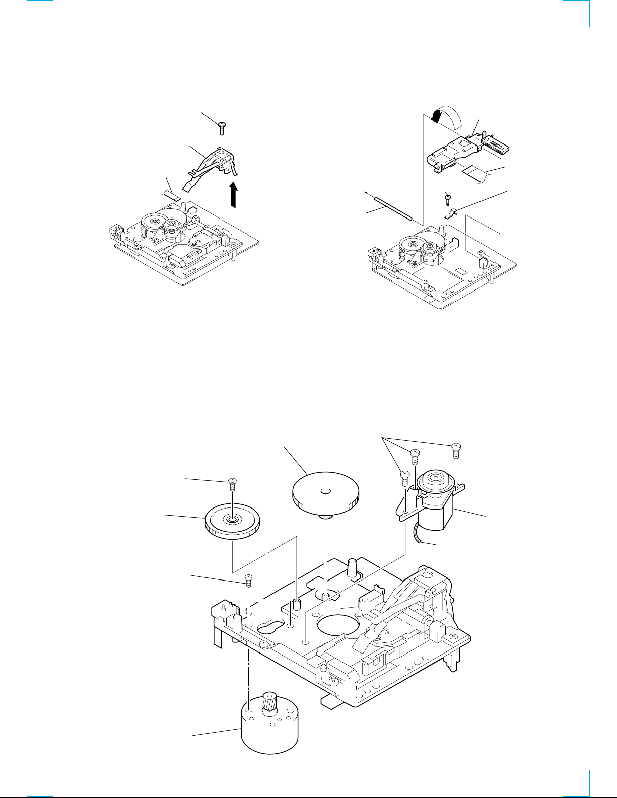
3-5. SLIDER (CAM)
• Note for installation of Slider (CAM)
Set the shaft of Cam gear to
be at the position in the figure.
Set the shaft of Lever (O/C) to
be at the position in the figure.
6 slider (cam)
2 bracket (guide L)
5 bracket (guide R)
4 two screws
(BTP 2.6x6)
1 two screws
(BTP 2.6x6)
3 leaf spring
A
When attaching the slider (cam),
this part of the over write head should
be inside arrow A.
2 base unit (MBU-5A)
1 three screws
(BTP 2.6x6)
5 screw
(M 1.7x4)
8 BD (MD) board
6 flexible board
7 flexible board
CN104
CN101
CN110
spindle motor
3 Remove the two solders.
Read wire's color
Red : +
Black :
-
4 Remove the two solders.
sled motor
-
+
3-6. BD BOARD
17
3-7. OVER WRITE HEAD
1 flexible board
2 screw (P 1.7x6)
3 over write head
(HR901)
1 screw (B 2x8)
3 main shaft
2 leaf spring
(SHAFT)
4 flexible board
5 optical pick-up (for MD
)
A
5 spindle motor
(M901)
7 sled motor
(M902)
4 three screws
(B 2x5)
6 two screws
(P 1.7x2.5)
1 screw (M1.7)
3 gear (SL-B)
2 gear (SL-A)
The BD (MD) board is soldered
at two parts.
(See page 16.)
3-8. OPTICAL PICK-UP
(KMS-260B/S1NP)
3-9. SPINDLE MOTOR, SLED MOTOR
Note:
Turn the optical pick-up
inside out, and pull out
the flexible board.
18
SECTION 4
TEST MODE
4-1. PRECAUTIONS FOR USE OF TEST MODE
• As loading related operations will be performed regardless of the test mode operations being performed, be sure to check that the disc is
stopped before setting and removing it.
Even if the A button (MD) is pressed while the disc is rotating during continuous playback, continuous recording, etc., the disc will not
stop rotating.
Therefore, it will be ejected while rotating.
Be sure to press the A button (MD) after pressing the MENU/NO button (MD) and the rotation of disc is stopped.
4-1-1. Recording laser emission mode and operating buttons
• Continuous recording mode (MD CREC MODE)
• Laser power check mode (MD LDPWR CHECK)
• Laser power adjustment mode (MD LDPWR ADJUST)
• Traverse (MO) check (MD EF MO CHECK)
• Traverse (MO) adjustment (MD EF MO ADJUST)
• When pressing the z REC button (MD).
4-2. SETTING THE TEST MODE
The following are two methods of entering the test mode.
1. Rotate the FUNCTION knob (TA), and set the function to “MD” before hand. When the power OFF (STANDBY), press the ?/1 button
(TA) while pressing the s button (MD) and ENTER/YES button (MD) together.
2. Press the MENU/NO button (MD), and when “MD Check” is displayed.
3. When the test mode is set, “MD [Check]” will be displayed. Rotate the l L knob (MD) switches between the following four
groups; ···Tt MD Check Tt MD Adjust Tt MD Service Tt MD Develop Tt ···.
4-3. EXITING THE TEST MODE
Press the ?/1 button (TA). The disc is ejected when loaded, and “Standby” display blinks, and the STANDBY state is set.
4-4. BASIC OPERATIONS OF THE TEST MODE
All operations are performed using the l L knob (MD), ENTER/YES button (MD), and MENU/NO button (MD).
The functions of these buttons are as follows.
Function name
l L knob (MD)
ENTER/YES button (MD)
MENU/NO button (MD)
Function
Changes parameters and modes
Proceeds onto the next step. Finalizes input.
Returns to previous step. Stops operations.
 Loading...