

Page 1
4-230-661-11(1)
MiniDisc Deck
Operating Instructions
MDS-PC3
2000 Sony Corporation
Page 2
WARNING
To prevent fire or shock hazard, do not
expose the unit to rain or moisture.
Do not install the appliance in a confined space, such
as a bookcase or built-in cabinet.
This appliance is classified as a CLASS 1 LASER
product.
The CLASS 1 LASER PRODUCT MARKING is
located on the bottom exterior.
The following caution label is located inside the unit.
IN NO EVENT SHALL SELLER BE LIABLE
FOR ANY DIRECT, INCIDENTAL OR
CONSEQUENTIAL DAMAGES OF ANY
NATURE, OR LOSSES OR EXPENSES
RESULTING FROM ANY DEFECTIVE
PRODUCT OR THE USE OF ANY PRODUCT.
For the customers in the U.S.A.
This symbol is intended to alert the user to
the presence of uninsulated “dangerous
voltage” within the product’s enclosure that
may be of sufficient magnitude to constitute
a risk of electric shock to persons.
This symbol is intended to alert the user to
the presence of important operating and
maintenance (servicing) instructions in the
literature accompanying the appliance.
If you have any questions about this product, you may
call:
Sony Customer Information Services Center 1-800488-7669
2
The number below is for the FCC related matters
only.
Declaration of Conformity
Trade name: SONY
Model No.: CAV-MN10
Responsible Party: Sony Electronics Inc.
Address: 1 Sony Drive, Park Ridge,
Telephone No.: 201-930-6972
This device complies with Part 15 of the FCC Rules.
Operation is subject to the following two conditions:
(1) This device may not cause harmful interference,
and (2) this device must accept any interference
received, including interference that may cause
undesired operation.
NJ. 07656 USA
INFORMATION
This equipment has been tested and found to comply
with the limits for a Class B digital device, pursuant
to Part 15 of the FCC Rules. These limits are
designed to provide reasonable protection against
harmful interference in a residential installation. This
equipment generates, uses, and can radiate radio
frequency energy and, if not installed and used in
accordance with the instructions, may cause harmful
interference to radio communications. However,
there is no guarantee that interference will not occur
in a particular installation. If this equipment does
cause harmful interference to radio or television
reception, which can be determined by turning the
equipment off and on, the user is encouraged to try to
correct the interference by one or more of the
following measures:
• Reorient or relocate the receiving antenna.
• Increase the separation between the equipment and
receiver.
• Connect the equipment into an outlet on a circuit
different from that to which the receiver is
connected.
• Consult the dealer or an experienced radio/TV
technician for help.
CAUTION
You are cautioned that any changes or modification
not expressly approved in this manual could void
your authority to operate this equipment.
Owner’s Record
The model and serial numbers are located on the
bottom of the unit. Record the serial number in the
space provided below. Refer to them whenever you
call upon your Sony dealer regarding this product.
Model No. MDS-PC3
Serial No.
For the customers in Canada
CAUTION
TO PREVENT ELECTRIC SHOCK, DO NOT USE
THIS POLARIZED AC PLUG WITH AN
EXTENSION CORD, RECEPTACLE OR OTHER
OUTLET UNLESS THE BLADES CAN BE FULLY
INSERTED TO PREVENT BLADE EXPOSURE.
Page 3

Welcome!
Thank you for purchasing the
Sony MiniDisc Deck. Before
operating the deck, please read
this manual thoroughly and
retain it for future reference.
About This
Manual
The instructions in this manual
are for the MDS-PC3 MiniDisc
Deck.
Conventions
• Controls in these instructions
are those on the supplied
remote; these may, however,
be substituted by controls on
the deck that are similarly
named, or, when different,
appear in the instructions
within parentheses.
Example: Press x (or x/Z
on the deck).
• z indicates hints and tips for
making the task easier.
Table of Contents
Location and
Function of Parts
Front Panel Parts
Description......................4
Remote Parts
Description......................5
Using the Display ..............6
Getting Started
Before You Start the
Hookup ...........................8
Hooking Up .......................9
Recording on MDs
Notes on Recording .........11
Recording on an MD .......12
Adjusting the Recording
Level ............................. 14
Recording for Long
Times ............................ 15
Recording Tips ................ 16
Marking Track Numbers
While Recording
(Track Marking)............18
Synchro-recording With the
Audio Component of Your
Choice (Music Synchro-
recording)......................20
Editing Recorded
MDs
Erasing Tracks ................. 29
Dividing Tracks ............... 31
Combining Tracks ...........33
Moving Tracks ................ 34
Naming Tracks or MDs ... 35
Undoing the Last Edit......38
Changing the Track Level
After Recording
(S.F Edit).......................39
Other Functions
Fade In and Fade Out
Recording/Playback ...... 42
Additional Information
Precautions ...................... 43
Handling MDs .................44
System Limitations .......... 44
Troubleshooting...............46
Specifications .................. 47
Display Messages ............48
Edit Menu Table .............. 49
Setup Menu Table ...........50
Self-Diagnosis
Function ........................ 51
Index .................. Back cover
Playing MDs
Playing an MD.................21
Playing a Specific Track..22
Locating a Particular Point
in a Track ......................22
Playing Tracks
Repeatedly .................... 23
Playing Tracks in Random
Order (Shuffle Play)......24
Creating Your Own Program
(Program Play) .............. 25
Tips for Recording From
MDs to Tape ................. 27
3
Page 4
Location and Function of Parts
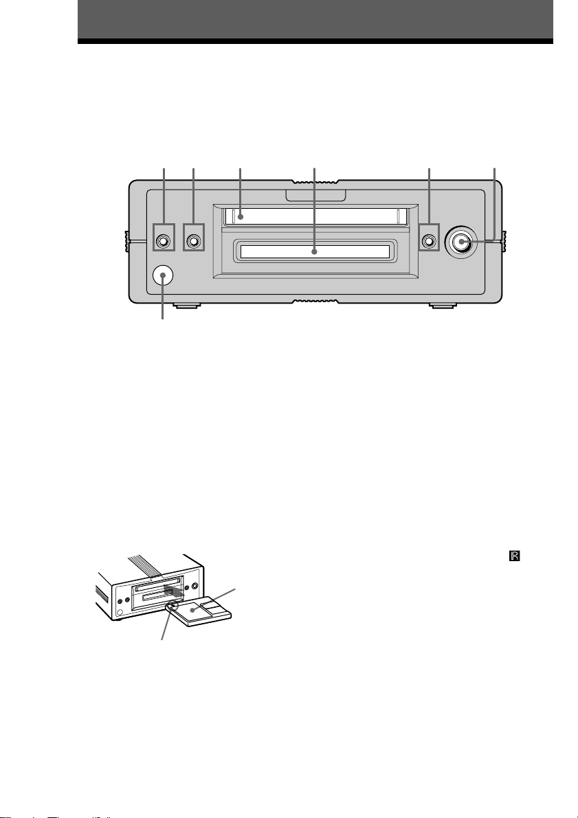
Front Panel Parts Description
This chapter tells you about the location and function of the various buttons and controls on the front panel
and the supplied remote. Further details are provided on the pages indicated in the parentheses.
It also tells you about the information that appears in the display window.
1723 4 5 6
?/1 z x/Z
g
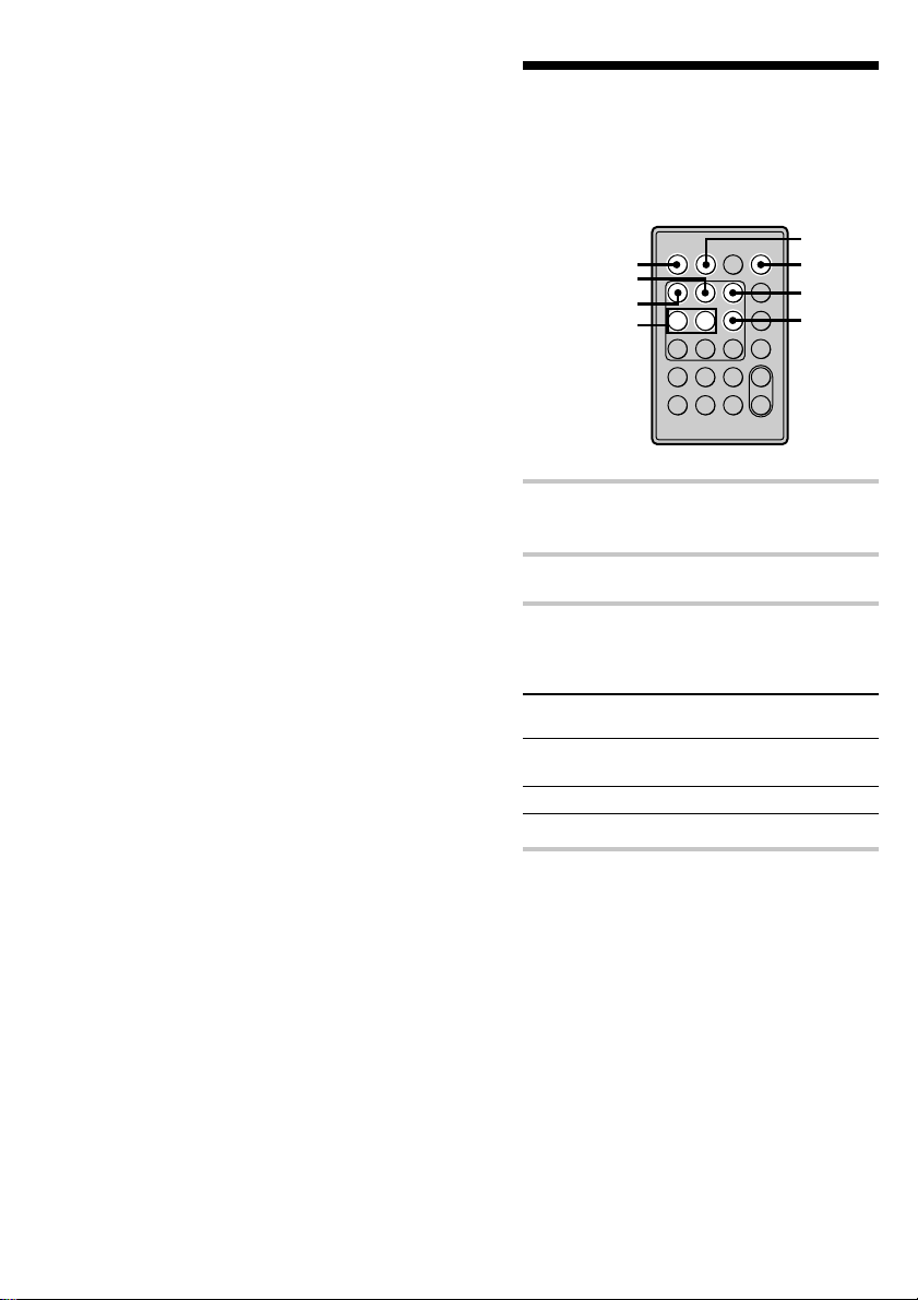
1 ?/1 (power) switch (12, 21)
Press to turn the deck on. When you turn the
deck on, the switch indicator turns off. When
you press the switch again, the deck turns off and
the indicator lights up red.
2 z button (13, 17, 18)
Press to record on the MD, monitor the input
signal, or mark track numbers.
3 MD insertion slot
Insert the MD as illustrated below.
With the labeled
side up
.>
PUSHu
5 x/Z button (13, 21, 29)
Press to stop play, stop recording, or cancel the
selected operation.
Press to eject the MD while the deck is stopped.
6 ./> control, u button (13, 21,
22, 25, 28)
Turn to locate tracks.
Press to start play, pause play, or pause recording.
Press to carry out the selected operation.
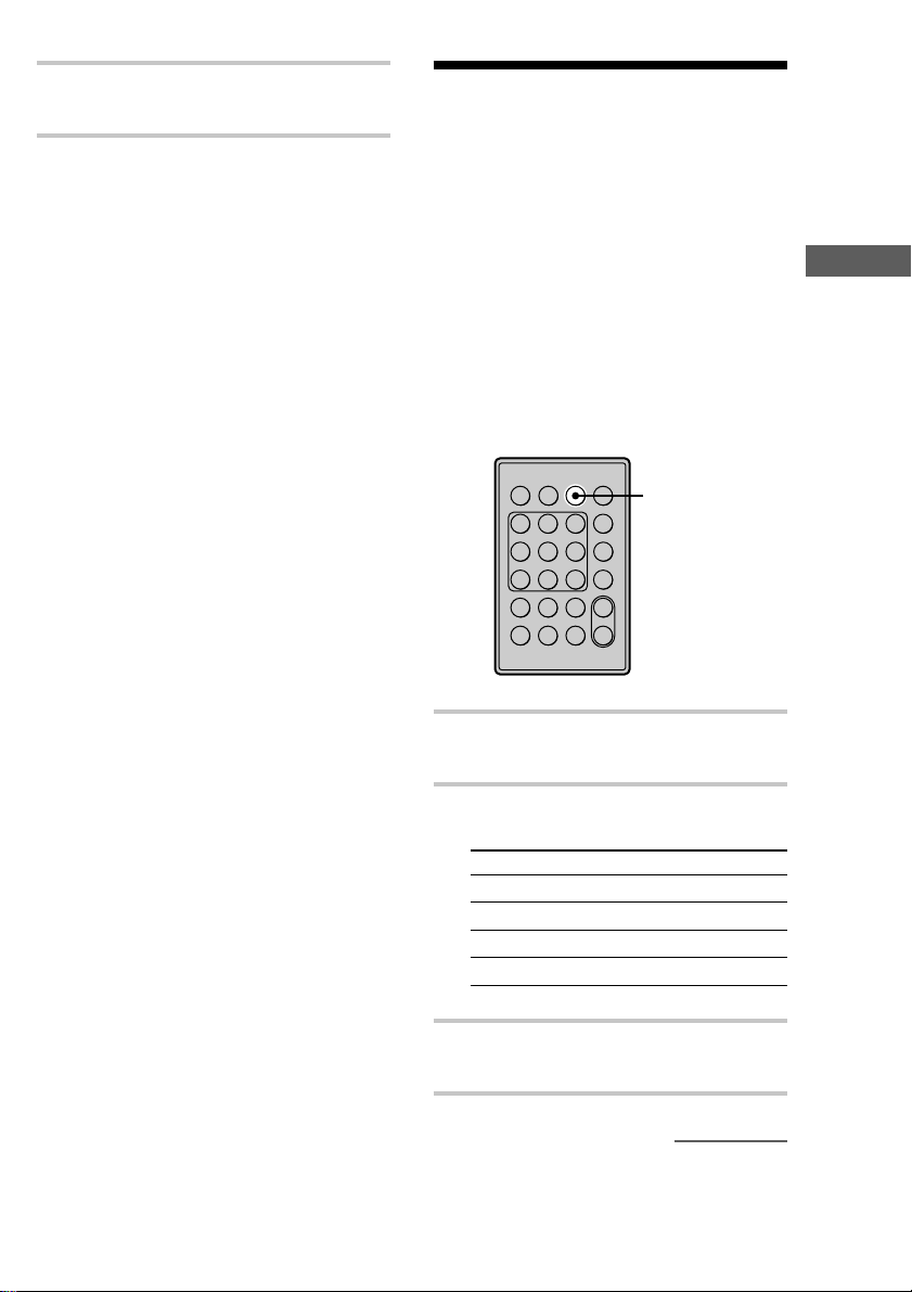
7 Remote sensor
Point the remote towards this window ( ) for
remote operations.
With the arrow pointing
towards the deck
4 Display window (6, 7)
Shows various information.
4
Page 5
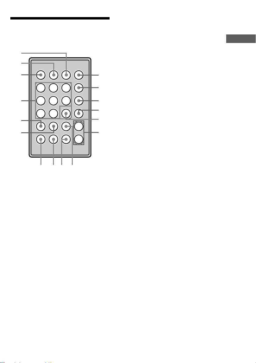
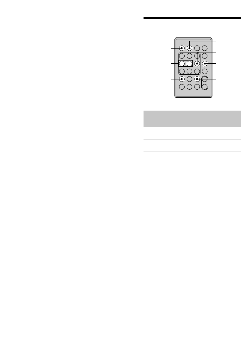
Remote Parts
Description
qh
qg
qf
qd
qs
qa
1 ?/1 (power) switch (12, 21)
Press to turn the deck on. When you turn the
deck on, the ?/1 switch indicator on the deck
turns off. When you press the switch again, the
deck turns off and the indicator lights up red.
2 PLAY MODE button (24, 25)
Press to select Shuffle Play or Program Play.
3 DISPLAY button (6, 16, 25, 35)
Press to select the information to be displayed in
the window, or to select the type of characters to
be input.
4 MUSIC SYNC button (20)
Press to start Music Synchro-recording.
5 FADER button (42)
Press to perform Fade-in Recording/Playback or
Fade-out Recording/Playback.
6 LEVEL +/– buttons (14, 21)
Press to adjust the recording level and the output
level of the PHONES jack and ANALOG OUT
jacks.
7 YES button (15, 25, 28)
Press to carry out the selected operation.
8 CLEAR button (26, 36)
Press to cancel the selection.
EJECT INPUT
6
(
=+
0)
MENU/NO NAME EDIT/
REPEAT AyB CLEAR
REC MODE
Pp
r
FADER
YES
SELECT
q; 98 7
1/u
PLAY MODE
DISPLAY
MUSIC SYNC
+
LEVEL
–
g
1
2
3
4
5
6
9 AyB button (23)
Press to select Repeat A-B Play.
0 REPEAT button (23)
Press to play tracks repeatedly.
qa NAME EDIT/SELECT button (37)
Press to add the name or change the name of a
track or MD.
qs MENU/NO button (15, 25, 28)
Press to display “Edit Menu” or “Setup Menu.”
qd N button (13, 21)
Press to start play or recording.
X button (13, 21)
Press to pause play or recording. Press again to
resume play or recording.
x button (13, 21, 29)
Press to stop play, recording, or cancel the
selected operation.
./> buttons (13, 21, 22, 25, 28)
Press to locate tracks, select a menu item, or
select a character to be input.
z button (13, 17, 18)
Press to record on the MD, monitor the input
signal, or mark track numbers.
m/M buttons (22, 26, 36)
Press to locate a portion within a track, change
the contents of a program, or shift the cursor.
qf EJECT Z button (13, 21)
Press to eject the MD.
qg INPUT button (12)
Press to select the input jack (or connector) of the
program source to be recorded.
qh REC MODE button (15)
Press to select one of the following four
recording modes: Mono (monaural recording),
stereo (stereo recording), LP2 (2 times normal
recording time), and LP4 (4 times normal
recording time).
Location and Function of Parts
5
Page 6
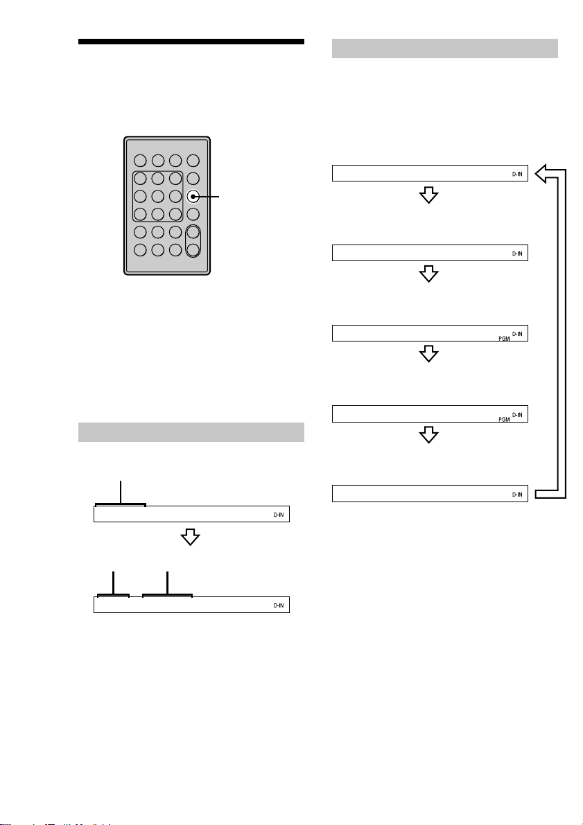
Using the Display
The display window shows information about the
MD or track. This section describes the
information that appears for each deck status.
While the deck is stopped
Press DISPLAY repeatedly to change the
display.
Each press of the button changes the display as
follows:
Xx
z
?/1
DISPLAY
Z
N
.>
mM
+
–
g
Note
The type of information (e.g., total number of tracks,
recorded time, remaining time, track or disc name)
which was last displayed will continue to appear until
you change it by pressing DISPLAY, even if you
change the deck operation status. For example, if the
remaining time was displayed when you stop the
deck, the remaining time will continue to appear
when you begin playing the same MD again or a
different one.
When you insert an MD
The display automatically changes as follows:
Disc name
SONGS
Total number
of tracks
Total recorded
time
Total number of tracks and total
recorded time (default display)
14Tr 44.22
Press
Remaining recordable time on the
MD (recordable MDs only)*
-63.51
Press
Order of the programmed tracks**
12t 4 t 61
Press
The number and total playing time of the
programmed tracks**
3Tr 12.56
Press
Disc name
SONGS
* Not shown for the premastered discs.
** This display appears only when “PGM” appears.
Press
14Tr 44.22
6
Page 7
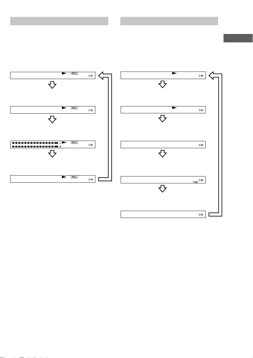
While the deck is recording
Press DISPLAY repeatedly to change the
display.
Each press of the button changes the display as
follows:
While the deck is playing
Press DISPLAY repeatedly to change the
display.
Each press of the button changes the display as
follows:
Location and Function of Parts
Track number and recorded time of
the current track (default display)
15Tr 44.22
Press
Remaining recordable time on the MD
-63.02
Press
Level of the input signal
Press
Track name
SONGS
Press
Track number and elapsed time of the
current track (default display)
1Tr 0.12
Press
Track number and remaining time of
the current track
1Tr-2.51
Press
Remaining recordable
time on the MD
-45.25
Press
Order of the programmed
tracks*
12t 4 t 61
Press
Track name
Track2
* The display appears only when “PGM” appears.
Press
7
Page 8
Getting Started
Before You Start the
Hookup
Checking the supplied
accessories
This MD deck comes with the following items:
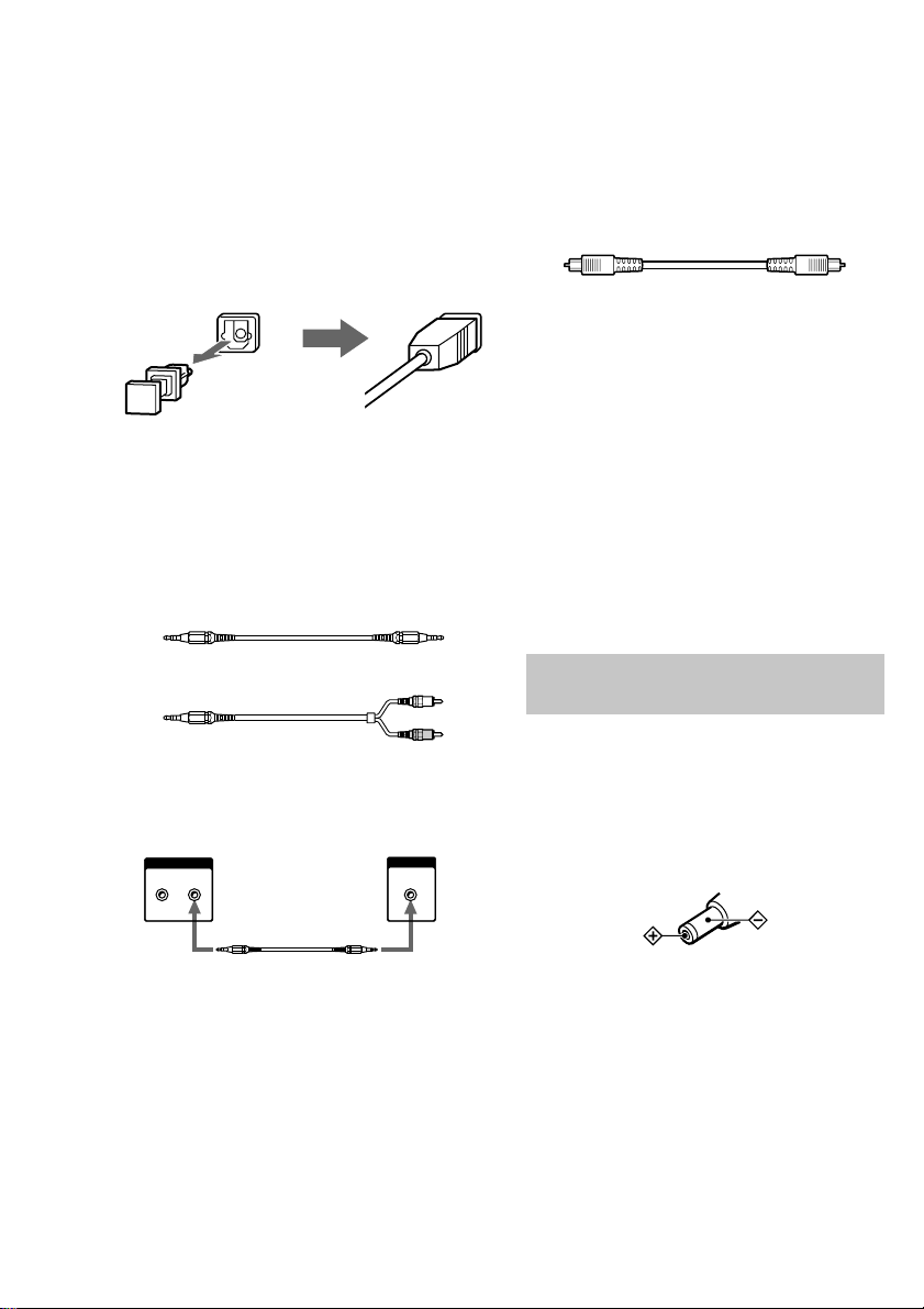
• AC power adaptor (1)
• Audio connecting cord
(stereo mini-plug × 1 y stereo mini-plug × 1)
(1)
• Optical cable (1)
• Remote commander (remote) RM-D52M (1)
• PC connecting kit PCLK-MN10* (1)
* Required for operation by personal computer. For
details, refer to the operating instructions supplied
with the PCLK-MN10.
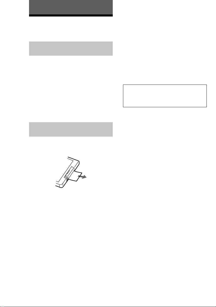
Before using the supplied
remote
The supplied remote already contains a battery.
Before using the remote, pull out the insulating
sheet to allow the power to flow from the battery.
z
When to replace the battery
Under normal conditions, the battery should last for
about six months. When the remote no longer
operates the deck, replace the battery with new one.
Notes on lithium battery
• Keep the lithium battery out of the reach of the
children. Should the battery be swallowed,
immediately consult a doctor.
• Wipe the battery with a dry cloth to assure a good
contact.
• Be sure to observe the correct polarity when
inserting the battery.
• Do not hold the battery with metallic tweezers,
otherwise a short-circuit may occur.
WARNING
Battery may explode if mistreated.
Do not recharge, disassemble, or dispose of in
fire.
To avoid battery leakage
If you don’t use the remote for an extended period of
time, remove the battery to avoid possible damage
from battery leakage and corrosion.
8
Page 9
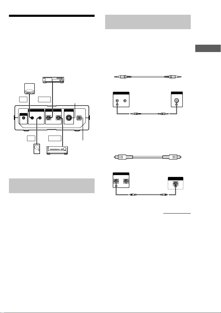
Hooking Up
The MD deck can be connected to PCs with PC
LINK capability (such as the VAIO-series of
PCs), peripheral devices such as portable CD
players, and active speakers. Make sure all devices
are turned off before you hook them up.
CD player or digital CS tuner,
etc. with optical digital
Portable CD
player, etc.
LINE
OUT
PHONES
Active
speakers,
etc.
l : Signal flow
Connecting the MD deck to a
personal computer
Use the PCLK-MN10 PC connecting kit
(supplied) to connect the PC to the MD deck
through the PC LINK jack on the back of the MD
deck. By connecting the MD deck to a PC, you
will be able to select and play MD tracks and do
various editing operations on the PC screen.
For more details, refer to the manual supplied with
the PC connecting kit.
connection capability
OPTICAL
OUT
Ç
(VARIABLE)
IN OUTIN OUT
(OPTICAL)
LINE
IN
OPTICAL
IN
Ç
Amplifier, etc. with
optical digital
connection capability
For PC connecting
kit PCLK-MN10
Ç
PC LINKDIGITALANALOG
!
DC IN
Ç
For AC
power
adaptor
9V
Connecting the MD deck with
an audio component
The MD deck is capable of recording from both
analog and digital sources.
When recording from an analog
source
Required connecting cord
Audio connecting cord (supplied)
Portable CD
player, etc.MDS-PC3
ANALOG
(VARIABLE)
IN OUT
Ç
l : Signal flow
When recording from a digital
source
Required connecting cord
Optical digital cable (supplied)
MDS-PC3
DIGITAL
IN OUT
(OPTICAL)
l : Signal flow
CD player, etc. with optical
digital connection capability
Ç
LINE
OUT
OPTICAL
OUT
continued
Getting Started
9
Page 10
Hooking Up (continued)
Notes
• Insert plugs into jacks firmly. Loose connections
may be a cause of noise or malfunction in the MD
deck.
• When connecting an optical digital cable, take the
caps off the connectors and insert the cable plugs
straight in the jacks until you hear a click.
When a plug is not completely inserted, “C71” and
“Din Unlock” may alternate in the display.
Do not bend or tie the optical cable.
Connecting the MD deck to
active speakers, etc.
Required connecting cord
Audio connecting cord (stereo mini-plug × 1 y
stereo mini-plug × 1) (supplied) or audio connecting
cord (stereo mini-plug× 1 y pin-plug × 2)
Connecting the MD deck to a
system stereo or an amplifier
By connecting the MD deck to a system stereo or to
an amplifier with optical digital input jacks, you can
enjoy listening to MDs on the speakers connected to
the system stereo or the amplifier.
Required connecting cord
Optical digital cable (supplied)
z
You can change the output level
of the ANALOG OUT jacks
1While the deck is stopped, press MENU/NO twice
to display “Setup Menu.”
2Press ./> repeatedly (or turn ./> on
the deck) until “Aout” appears, then press YES (or
./> on the deck).
3Press ./> repeatedly (or turn ./> on
the deck) to change the output level, then press YES
(or ./> on the deck).
4Press MENU/NO.
You can also change the level with LEVEL +/–. In
such a case, note that the output level of the PHONES
jack will change with the output level of the
ANALOG OUT jacks (page 21).
or
The example below shows the MD deck connected to
active speakers with an audio connecting cord (stereo
mini-plug × 1 y stereo mini-plug × 1) (supplied).
Active speakers, etc.MDS-PC3
ANALOG
(VARIABLE)
IN OUT
Ç
l : Signal flow
10
LINE
Connecting the AC power
adaptor
Connect the AC power adaptor to the DC IN 9 V jack
on the MD deck and to a wall outlet.
Notes
• Do not connect the AC power adaptor to a switched
outlet.
• Use only the supplied AC power adaptor. Do not
IN
use any other AC power adaptor.
Polarity of the plug
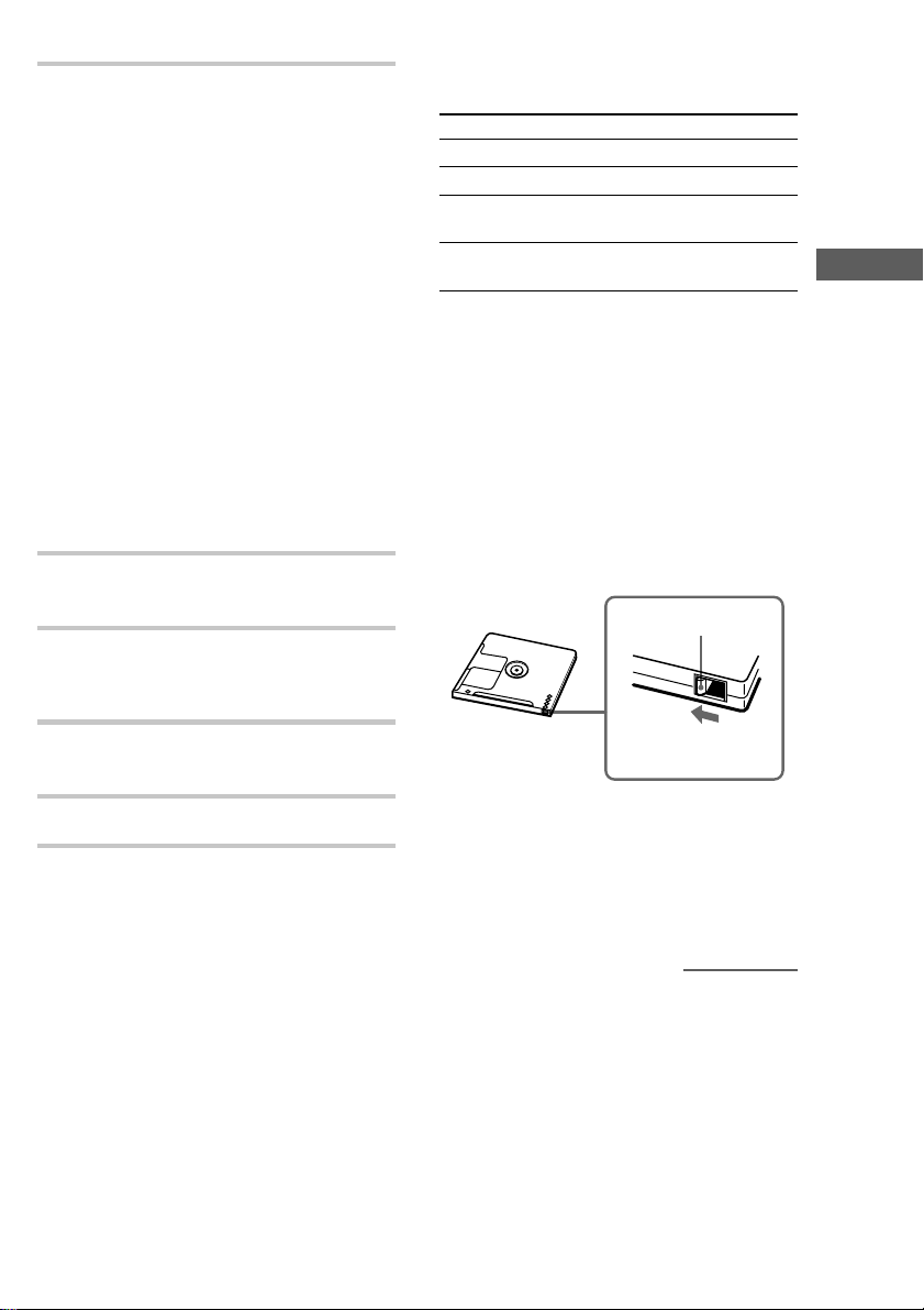
Page 11

Recording on MDs
Notes on Recording
About indications which
appear while recording
When “Protected” and “C11”
alternate in the display
The record-protect slot is open and the MD is
record-protected. To record on the MD, slide the
tab to close the slot. For details, see “To prevent
accidental erasure of the recorded material” on
page 13.
When “Din Unlock” and “C71”
alternate in the display
• The digital component selected with INPUT is
not connected correctly. Check the connection.
• The selected digital component is not turned on.
Turn on the component.
When “Cannot Copy” and “C41”
alternate in the display
The MD deck uses the Serial Copy Management
System. MDs recorded through the digital input
connector can’t be copied to other MDs or DAT
tapes through the digital output connector. For
details, see “Guide to the Serial Copy
Management System” on page 11.
When “Tr” flashes in the display
The MD deck is recording over existing track(s)
(“Recording on an MD” on page 13). The
indication stops flashing when the deck reaches
the end of the recorded portion.
About indications which
appear after recording
When “TOC” lights up in the
display
Recording has finished but the TOC (Table of
Contents) on the MD has not been updated to
reflect the recording results. The recording will be
lost if you disconnect the AC power adaptor while
the indication is on. The TOC will be updated
only when you eject the MD or turn off the MD
deck.
When “TOC Writing” flashes in
the display
The deck is updating the TOC. Do not disconnect
the AC power adaptor or move the deck while the
indication flashes.
Automatic conversion of
digital sampling rates during
recording
A built-in sampling rate converter automatically
converts the sampling frequency of various digital
sources to the 44.1 kHz sampling rate of the MD
deck. This allows you to monitor and record
sources such as 32- or 48-kHz DAT tapes or
satellite broadcasts, as well as the CDs and MDs.
Please note that 22.05- or 96-kHz digital sources
can’t be recorded on this deck.
Guide to the Serial Copy
Management System
Digital audio components, such as CDs, MDs, and
DATs make it easy to produce high-quality copies
of music by processing music as a digital signal.
To protect copyrighted music sources, this deck
uses the Serial Copy Management System which
allows you to make only a single copy of a
digitally recorded source through digital-to-digital
connections.
Recording on MDs
Getting Started/Recording on MDs
continued
11
Page 12
Notes on Recording (continued)
You can make only a firstgeneration copy* through a
digital-to-digital connection.
Examples are given as follows:
• You can make a copy of a commercially
available digital sound program (for example, a
CD or MD), but you can’t make a second copy
from the first-generation copy.
• You can make a copy of a digital signal from a
digitally recorded analog sound program (for
example, an analog record or a music cassette
tape) or from a digital satellite broadcast
program, but you can’t make a second copy
from the first-generation copy.
* A first-generation copy means the first recording of
a digital audio source through the deck’s digital
input connector. For example, if you record from a
CD player connected to the DIGITAL (OPTICAL)
IN connector, that copy is a first-generation copy.
Note
The restrictions of the Serial Copy Management
System don’t apply when you make a recording
through the analog-to-analog connections.
Recording on an MD
The operations for normal recording are explained
below. If the MD has recorded material on it, the
deck will automatically start recording from the
end of the recorded portion.
INPUT
Xx
Select
Optical In
?/1
?/1
x
z
+
–
g
Z
Z
X
N
N
./>
.> z
mM
1 Press ?/1 to turn on the deck.
The switch indicator on the deck turns off.
2 Insert a recordable MD (page 4).
3 Press INPUT repeatedly to select the
input jack (connector) connected to the
program source.
If the source is connected
to the
DIGITAL (OPTICAL) IN
connector
LINE (ANALOG) IN jack Analog In
12
4 If necessary, select the recording mode.
For details, see “Recording for Long Times”
on page 15.
Page 13
5 If necessary, locate the point on the MD
to start recording from.
If you want to record on a new MD or start
recording from the end of the recorded
portion, go to step 6.
To record over from the
beginning of an existing MD
track
Press ./> repeatedly (or turn
./> on the deck) until the number of
the track to be recorded over appears.
To record over from the middle
of an MD track
Press ./> repeatedly (or turn
./> on the deck) until the number of
the track to be recorded over appears, then
press N (or NX on the deck) to start
playback. Press X (or NX on the deck),
then z at the point you want to start
recording from.
6 Press z.
The deck changes to recording pause.
7 If necessary, adjust the recording level.
For details, see “Adjusting the Recording
Level” on page 14.
Operations you may want to do
during recording
To Press
Stop recording x (or x/Z on the deck)
Pause recording X (or NX on the deck)
Resume recording
after pausing
Eject the MD EJECT Z (or x/Z on the
N or X (or NX on the
deck)
deck) after stopping recording
When you pause recording
The track number increases by one. For example,
if you paused recording while recording track 4,
the track number will be 5 when you resume
recording.
To prevent accidental erasure of
the recorded material
To make it impossible to record on an MD, slide
the record-protect tab in the direction of the arrow
(see illustration below) to open the slot. To enable
recording, close the slot.
Bottom side
of the MD
Record-protect tab
Recording on MDs
8 Press N or X (or NX on the deck).
Recording starts.
9 Start playing the program source.
Slide in the direction
of arrow
z
To play the tracks you just
recorded
Press N (or NX on the deck) immediately after
stopping recording.
The deck starts to play from the first track of the
material just recorded.
continued
13
Page 14
Recording on an MD (continued)
z
To play from the first track of the
MD after recording
1Press x (or x/Z on the deck) again after stopping
recording.
2Press N (or NX on the deck).
The deck starts to play from the first track of the
MD.
Note
You can’t record over existing material when Shuffle
Play (page 24) or Program Play (page 25) has been
selected. “Impossible” appears in the display at this
time.
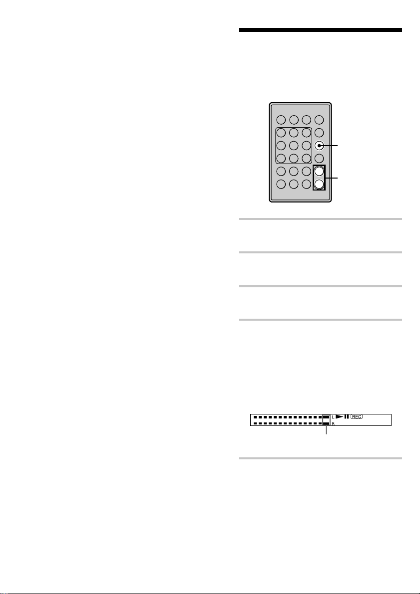
Adjusting the Recording
Level
Do the procedure below to adjust the recording
level.
Xx
?/1
+
–
DISPLAY
LEVEL +/–
g
Z
N
.> z
mM
1 Do steps 1 to 6 of “Recording on an
MD” on pages 12 and 13.
2 Play the portion of the program source
with the strongest output.
3 Press DISPLAY repeatedly until the
peak level meters appear.
14
4 While monitoring the sound, press
LEVEL +/– repeatedly (or turn
./> on the deck) to adjust the
recording level to its highest level
without turning on the rightmost
indicators on the peak level meters.
Occasional lighting of the indicators is
acceptable.
Make sure that those indicators do
not always turn on.
5 Stop playing the program source.
Page 15
?/1
Z
N
Xx
.> z
mM
–
+
g
REC MODE
6 To start recording, continue from step 8
of “Recording on an MD” on page 13.
z
You can adjust the recording
level during recording or recording
pause
Press LEVEL +/– repeatedly.
z
To display the level of the
strongest signal
The Peak Hold function continuously displays the
level of the strongest signal that has been input.
Do the procedure below to turn Peak Hold on.
1While the deck is stopped, press MENU/NO twice
to display “Setup Menu.”
2Press ./> repeatedly (or turn ./> on
the deck) until “P.Hold” appears, then press YES
(or ./> on the deck).
3Press ./> (or turn ./> on the deck)
to select “P.Hold On,” then press YES (or ./
> on the deck).
4Press MENU/NO.
To turn Peak Hold off, selecte “P.Hold Off” in step 3
above.
z
You can also change the input
level of the ANALOG IN jacks or
DIGITAL IN connector by accessing
the “Setup Menu”
1While the deck is stopped, press MENU/NO twice
to display “Setup Menu.”
2Press ./> repeatedly (or turn ./> on
the deck) until “Ain” (for the analog input) or “Opt”
(for the digital input) appears, then press YES (or
./> on the deck).
3Press ./> repeatedly (or turn ./> on
the deck) to change the input level, then press YES
(or ./> on the deck).
4Press MENU/NO.
Note
The maximum recording level is + 18.0 dB for digital
recordings, and +12.0 dB for analog recordings. The
maximum recording level may still be inadequate for
producing a proper recording if the output level of the
source component is extremely low.
Recording for Long
Times
In addition to normal stereo recording, this deck
has two recording modes: LP2 and LP4. When
recording in LP2 mode, you can record 2 times the
normal recordable time, and in LP4 mode, you can
record 4 times the normal recordable time. In
addition, the recordable time for monaural
recording is approximately double the stereo
recording time.
Note
MDs recorded in LP2 or LP4 mode can be played
back only on decks that support the MD LP format.
Conventional MD decks cannot play MDs recorded in
LP2 or LP4 mode.
1 Do steps 1 to 3 of “Recording on an
MD” on page 12.
2 Press REC MODE repeatedly to select
the recording mode.
To record in Select to light up
Stereo (factory setting) no indicator
LP2 stereo LP2
LP4 stereo LP4
Monaural Mono
Recording on MDs
3 Do steps 5 to 9 of “Recording on an
MD” on page 13.
continued
15
Page 16
Recording for Long Times
(continued)
Notes
• Even if you press REC MODE during recording or
recording pause, you cannot change the recording
mode.
• Even if you select the monaural recording mode, the
sound from the speakers will be the same as the
source sound (e.g. Stereo source sound will be as it
is).
z
LP Stamp function works during
recording in LP2 or LP4 mode
A track recorded in LP2 or LP4 mode is given an
identification code which is displayed only when you
attempt to play that track on an MD deck which does
not support LP modes. “LP:” appears in the display
at this time. To turn off this function, do the
procedure below.
1While the deck is stopped or playing, press MENU/
NO twice.
“Setup Menu” appears in the display.
2Press ./> repeatedly (or turn ./> on
the deck) until “LPstamp On” appears, then press
YES (or ./> on the deck).
3Press ./> (or turn ./> on the deck)
to select “LPstamp Off,” then press YES (or ./
> on the deck).
4Press MENU/NO.
To turn on the LP Stamp function again, select
“LPstamp On” in step 3 above.
Notes
•“LP:” does not appear when the track is played back
on the MD deck that supports the MD LP format.
• When the LP Stamp function is on, the maximum
number of text characters that can be stored on the
MD decreases.
• When you divide a track that was recorded with the
LP Stamp function on, the “LP:” code is copied to
the newly created track.
Recording Tips
INPUT
Z
Z
N
./>
.>
mM
Checking the remaining
recordable time on the MD
Press DISPLAY repeatedly.
While the deck is The following information
Stopped Total number of tracks and
Recording Recorded time of the current
For details, see pages 6 and 7.
?/1
Xx
z
r
DISPLAY
+
YESMENU/NO
–
g
appears
total recorded time t
Remaining recordable time on
the MD t Order of the
programmed tracks t
Number of the programmed
tracks and total playing time
the programmed tracks t
Disc name
track t Remaining
recordable time on the MD t
Input level indication t
Track name
16
Page 17

Monitoring the input signal
(Input Monitor)
You can monitor the selected input signal even
when you’re not recording it.
1 Press EJECT Z (or x/Z on the deck)
to eject the MD.
2 Press INPUT repeatedly to select the
jacks (connectors) which the signal you
want to monitor is being input.
3 Press z.
When “A-IN” is selected
The analog signal input from the LINE
(ANALOG) IN jacks is output to the
DIGITAL (OPTICAL) OUT connector after
A/D conversion, and then to the LINE
(ANALOG) OUT jacks after D/A
conversion. “AD - DA” appears in the
display at this time.
When “D-IN” is selected
The digital signal input from the DIGITAL
(OPTICAL) IN connector first passes
through the sampling rate converter, and then
output to the DIGITAL (OPTICAL) OUT
connector, and then to the LINE (ANALOG)
OUT jacks after D/A conversion. “- DA”
appears in the display at this time.
To stop monitoring the signal
Press x (or x/Z on the deck).
Erasing blank portions
automatically (Smart Space/
Auto Cut)
The deck can be set to automatically erase any
blanks that are produced when the signal is
interrupted during recording. The function which
activates (Smart Space or Auto Cut) depends on
the length of the interruption, as described below.
Smart Space
If the signal is interrupted for less than 30
seconds, Smart Space replaces the blank portion
with a blank space of about three seconds, then
continues the recording. “Smart Space” appears
in the display during this time.
Auto Cut
If the signal is interrupted for about 30 seconds,
Auto Cut replaces the blank portion with a blank
space of about three seconds, then pauses the
recording. “Auto Cut” appears in the display
during this time.
Do the procedure below to turn Smart Space and
Auto Cut on or off.
1 While the deck is stopped, press
MENU/NO twice.
“Setup Menu” appears in the display.
2 Press ./> repeatedly (or turn
./> on the deck) until “S.Space”
appears, then press YES (or ./>
on the deck).
3 Press ./> repeatedly (or turn
./> on the deck) to select the
setting, then press YES (or ./>
on the deck).
To Select
Turn on Smart Space
and Auto Cut
Turn off Smart Space
and Auto Cut
S.Space On (factory setting)
S.Space Off
Recording on MDs
4 Press MENU/NO.
continued
17
Page 18

Recording Tips (continued)
Notes
• If you start recording with no signal input, Smart
Space and Auto Cut will not operate regardless of
the setting.
• Smart Space does not affect the order of the track
numbers being recorded, even if the blank space
occurs in the middle of a track.
• If the deck stays in recording-pause for about 10
minutes after the Auto Cut operation, the recording
operation will be automatically ended.
• Auto Cut is automatically turned on or off in
tandem with Smart Space.
• If you turn off the deck or disconnect the AC power
adaptor, the deck will store the last setting
(“S.Space On” or “S.Space Off”) and apply it the
next time you turn on the deck.
Marking Track Numbers
While Recording
(Track Marking)
You can mark track numbers either manually or
automatically while recording. By marking track
numbers at specific points, you can quickly locate
the points later or edit the MD easily.
Marking track numbers
manually (Manual Track
Marking)
Press z at the point where you want to
add a track number while recording.
18
Marking track numbers
automatically (Automatic
Track Marking)
When recording from a CD player or MD deck
connected to the DIGITAL (OPTICAL) IN
connector, the deck marks track numbers in the
same sequence as the source. When recording
from other sources connected to the DIGITAL
(OPTICAL) IN connector or a source connected to
the LINE (ANALOG) IN jacks, do the procedure
below to mark track numbers automatically.
Page 19

1 While the deck is stopped, press
MENU/NO twice.
“Setup Menu” appears in the display.
2 Press ./> repeatedly (or turn
./> on the deck) until “T.Mark”
appears, then press YES (or ./>
on the deck).
3 Press ./> (or turn ./> on
the deck) to select a desired setting, then
press YES (or ./> on the deck).
To Select
Turn on Automatic
Track Marking
Turn off Automatic
Track Marking
T.Mark LSync (factory
setting)
T.Mark Off
4 Press MENU/NO.
“L.SYNC” lights up.
The deck marks a track number whenever the
input signal level drops to –50 dB (the
trigger level for Automatic Track Marking)
or below for at least 1.5 seconds and then
rises over –50 dB.
To change the trigger level for
Automatic Track Marking
Do the procedure below to change the signal level
that triggers Automatic Track Marking.
1While the deck is stopped, press MENU/NO twice.
“Setup Menu” appears in the display.
2Press ./> repeatedly (or turn ./> on
the deck) until “LS(T)” appears, then press YES (or
./> on the deck).
3Press ./> repeatedly (or turn ./> on
the deck) to select the level, then press YES (or
./> on the deck).
You can set the level at any value between
–72 dB and 0 dB, in 2-dB steps.
4Press MENU/NO.
z
Additional information on
Automatic Track Marking
• When recording from a CD player or MD deck
connected to the DIGITAL (OPTICAL) IN
connector, the entire material may be recorded as a
single track in the following cases:
— When you consecutively record the same track
two or more times using single-track repeat
play.
— When you consecutively record two or more
tracks with the same track number but from
different CDs or MDs.
— When you record tracks from certain CD or
multi-disc players.
In such cases, divide the track by editing function
(page 31).
Recording on MDs
continued
19
Page 20

?/1
Z
N
Xx
.>
z
mM
–
+
g
MUSIC SYNC
Marking Track Numbers While
Recording (continued)
• Track marking may not occur in the following
tracks:
— Tracks that are less than 4 seconds long (in
stereo, monaural, or LP2 stereo mode).
— Tracks that are less than 8 seconds long (in LP4
stereo mode).
• When recording from a component connected to the
LINE (ANALOG) IN jacks with “T.Mark Off”
selected or when recording from a DAT deck or
DBS tuner connected to the DIGITAL (OPTICAL)
IN connector, the entire material may be recorded
as a single track.
• When recording from a DAT deck or DBS tuner
connected to the DIGITAL (OPTICAL) IN
connector, the deck will mark a track number
whenever the sampling frequency of the input
signal changes, regardless of the track marking
parameter setting (“T.Mark LSync” or “ T.Mark
Off”).
z
You can mark track numbers
even after recording has finished
See “Dividing Tracks” on page 31.
Notes
• If you turn off the deck or disconnect the AC power
adaptor, the deck will store the last settings
(“T.Mark LSync” or “ T.Mark Off” and the trigger
level) and apply them the next time you turn on the
deck.
• The entire contents of a radio broadcast or a cassette
may be recorded as a single track if it contains
static.
Synchro-recording With
the Audio Component of
Your Choice
(Music Synchro-recording)
The Music Synchro-recording allows you to
automatically synchronize recording on the MD
deck with the playing of the selected program
source. The Track Marking function, however,
will differ according to the program source. For
details, see “Marking Track Numbers While
Recording” on page 18.
1 Do steps 1 to 5 of “Recording on an
MD” on pages 12 and 13.
2 Press MUSIC SYNC.
The deck changes to recording pause.
20
3 Start playing the program source.
Recording starts automatically.
To stop Music Synchro-recording
Press x (or x/Z on the deck).
Note
During Music Synchro-recording, Smart Space and
Auto Cut will operate regardless of their setting
(“S.Space On” or “S.Space Off”) (page 17).
Page 21

Playing MDs
Playing an MD
The operations for normal play are explained
below.
N
./>
Z
Z
N
.>
mM
Xx
z
?/1
+
–
g
?/1
X
x
LEVEL +/–
Operations you may want to do
during play
To Press
Stop play x (or x/Z on the deck)
Pause play X (or NX on the deck)
Resume play after
pausing
Locate a succeeding
track
Locate the beginning
of the current track
or a preceding track
Eject the MD EJECT Z (or x/Z on the
N or X (or NX on the
deck)
> repeatedly (or turn
./> clockwise on the
deck)
. repeatedly (or turn
./> counterclockwise
on the deck)
deck) after stopping play
Playing MDs
Recording on MDs/Playing MDs
1 Turn on the amplifier and select MD on
the amplifier.
2 Press ?/1 to turn on the deck.
The switch indicator on the deck turns off.
3 Insert an MD (page 4).
4 If necessary, press ./>
repeatedly (or turn ./> on the
deck) to locate the track you want to
start playing from.
If you want to play from the first track, go to
step 5.
5 Press N (or NX on the deck).
The deck starts to play.
6 Adjust the volume on the amplifier.
z
When you play an MD recorded in
LP2 or LP4 stereo mode
“LP2” or “LP4” appears in the display when you
press N (or NX on the deck).
z
Using headphones
Connect headphones to the PHONES jack on the rear
of the deck. You can adjust the volume of the
headphones with LEVEL +/–. The output level of the
ANALOG OUT jacks changes with the volume of the
headphones, from – dB to 0 dB. This output is
factory set at – 14.0 dB. When recording from the
deck to another audio component, be sure to set the
output level to 0 dB (“ATT” turns off in the display).
21
Page 22

Playing a Specific Track
?/1
Z
N
Xx
.>
z
mM
–
+
g
m/M
Locating a Particular
You can use the following procedure while the
deck is playing, stopped, or paused to quickly find
the beginning of the next track you want to play.
Z
N
N
./>
Xx
.>
mM
Locating a track
To go to Do the following:
The next or a
succeeding track
during play
A preceding track
during play
The beginning of the
current track during
play
A specific track while
the deck is stopped
z
To locate the last track of the MD
quickly
While the deck is stopped, press . repeatedly (or
turn ./> counterclockwise on the deck).
z
If you locate a track while the
deck is stopped or paused
The deck will still be stopped or paused at the
beginning of the located track.
22
Press > repeatedly (or turn
./> clockwise on the
deck).
Press . repeatedly (or turn
./> counterclockwise
on the deck).
Press .(or turn ./>
counterclockwise on the deck)
once.
Press ./> repeatedly
(or turn ./> on the
deck) until the track number
you want to go to appears in
the display, then press N (or
NX on the deck).
Point in a Track
You can locate a particular point in a track during
play or play pause.
?/1
z
+
–
g
Locating a point while
monitoring the sound
Hold down m/M during play.
You will hear intermittent playback as the disc
goes forward or reverse. When you reach the
point, release the button.
Notes
• If the disc reaches the end while you’re pressing
M, the deck stops.
• Tracks that are only a few seconds long may be too
short for monitoring. For such tracks, play the MD
at normal speed.
Locating a point by observing
the time indication
Hold down m/M during play pause.
The elapsed playing time of the track appears in
the display. When you reach the point, release the
button. No sound is output during this time.
z
When “- Over -” appears in the
display
The disc has reached the end while you’re pressing
M. Press m (or turn ./>
counterclockwise on the deck) to go back.
Page 23

Playing Tracks
Repeatedly
You can play an entire MD repeatedly. This
function can be used with Shuffle Play to repeat
all the tracks in random order (page 24), or with
Program Play to repeat all the tracks in the
program (page 25). You can also repeat a specific
track or portion within a track.
Z
N
.>
mM
REPEAT
AyB
?/1
Xx
z
M
+
–
g
To stop Repeat All Play
Press x (or x/Z on the deck).
To resume normal play
Press REPEAT repeatedly until “Repeat Off”
appears in the display.
Repeating the current track
(Repeat 1 Play)
While the track you want to repeat is being
played, press REPEAT repeatedly until
“Repeat 1” appears in the display.
Repeat 1 Play starts.
To stop Repeat 1 Play
Press x (or x/Z on the deck).
To resume normal play
Press REPEAT repeatedly until “Repeat Off”
appears in the display.
Playing MDs
Note
If you turn off the deck or disconnect the AC power
adaptor, the deck will store the last setting of the
repeat play (“Repeat All” and “Repeat 1” only) and
recall it the next time you turn on the deck.
Repeating all the tracks on
the MD (Repeat All Play)
Press REPEAT repeatedly until “Repeat
All” appears in the display.
When you play an MD, the deck repeats the tracks
as follows:
When the play modeisThe deck repeats
Normal play (page 21) All the tracks in sequence
Shuffle Play (page 24) All the tracks in random
order
Program Play (page 25) All the tracks in the
program in sequence
Repeating a specific portion
within a track (Repeat A-B
Play)
You can specify one portion within a track to be
played repeatedly. Note that the portion that you
specify must be within the boundaries of a single
track.
1 While the deck is playing, press AyB
at the starting point (point A) of the
portion to be played repeatedly.
“REP A-” lights up and “B” flashes in the
display.
2 Continue playing the track or press M
to locate the ending point (point B),
then press AyB.
“REP A-B” lights up and Repeat A-B Play
starts.
continued
23
Page 24

Playing Tracks Repeatedly
(continued)
To stop Repeat A-B Play and
resume normal play
Press REPEAT or CLEAR.
z
You can set a new starting point
and ending point during Repeat A-B
Play
You can change the current ending point to a new
starting point, then specify a new ending point to
repeat a portion right after the current portion.
1During Repeat A-B Play, press AyB.
The current ending point changes to the new
starting point (point A).
“REP A-” lights up and “B” flashes in the display.
2Locate the new ending point (point B) and press
AyB.
“REP A-B” lights up and the deck starts to repeat
the newly specified portion.
Playing Tracks in
Random Order
When you select Shuffle Play, the deck plays all
the tracks on the MD in random order.
Z
N
N
1 While the deck is stopped, press PLAY
MODE repeatedly until “SHUF” lights
up in the display.
2 Press N (or NX on the deck).
Shuffle Play starts.
; appears while the deck is “shuffling” the
tracks.
Xx
.>
mM
(Shuffle Play)
?/1
PLAY MODE
z
+
–
g
24
To resume normal play
While the deck is stopped, press PLAY MODE
repeatedly until “SHUF” turns off.
z
You can locate tracks during
Shuffle Play
Press ./> repeatedly (or turn ./> on
the deck).
• To locate the next track or a later track to be played,
press > repeatedly (or turn ./> clockwise
on the deck).
• To locate the beginning of the current track, press
. (or turn ./> counterclockwise on the
deck). Note that you can’t locate and play the
tracks that have already been played once.
Page 25

Creating Your Own
N
(Program Play)
Z
N
.>
mM
?/1
Xx
z
+
–
p
PLAY MODE
DISPLAY
YES
CLEAR
g
Program
You can pick out the tracks that you like and
specify the playback order in a program
containing up to 25 tracks.
./>
m/M
Programming the tracks
1 While the deck is stopped, press
MENU/NO twice.
“Setup Menu” appears in the display.
2 Press ./> repeatedly (or turn
./> on the deck) until “Program
?” appears, then press YES (or ./
> on the deck).
3 Press ./> repeatedly (or turn
./> on the deck) until the track
number you want to add to the program
appears, then press M (or ./>
on the deck).
If you entered the wrong track
number
Press m/M repeatedly until the wrong
track number flashes, then do step 3 above
again.
To check the total playing time
of the program
Press DISPLAY.
4 Repeat step 3 to enter other tracks.
5 Press YES.
“Complete!!” appears and the program is
completed.
6 Press PLAY MODE repeatedly until
“PGM” lights up in the display.
7 Press N (or NX on the deck).
Program Play starts.
To stop Program Play
Press x (or x/Z on the deck).
To resume normal play
Press PLAY MODE repeatedly until “PGM” turns
off.
z
You can change the program
number of a track
If you press m while “0” is flashing, the number of
the last track in the program will begin to flash. You
can change the number at this time. You can also
change the number by pressing CLEAR to clear the
current number, and then entering the new number.
z
The program remains even after
Program Play ends or is stopped
Press N (or NX on the deck) to play the program
again.
Notes
• If you eject the MD or disconnect the AC power
adaptor, the program will be lost.
• The display shows “- - - . - -” when the total playing
time of the program exceeds 999 minutes.
•“ProgramFull!” appears when you program 25th
track.
continued
Playing MDs
25
Page 26

Creating Your Own Program
(continued)
Checking the contents of the
program
While the deck is stopped and “PGM”
lights up, press DISPLAY repeatedly.
The first several tracks in the program appear in
the display. To see the rest of the program, press
> repeatedly (or turn ./> clockwise on
the deck).
Changing the contents of the
program
While the deck is stopped and “PGM” lights up,
do steps 1 and 2 of “Programming the tracks” on
page 25, followed by one of the procedures below:
To Do the following:
Erase a track Press m/M repeatedly
Erase all tracks Press CLEAR repeatedly until
Add a track at the
beginning of the
program
Adding a track in the
middle of the program
Add a track to the end
of the program
Replace a track Press m/M repeatedly
until the number of the
unwanted track flashes, then
press CLEAR.
all the track numbers
disappear.
Press m repeatedly until “0”
flashes before the first track
number, then do steps 3 to 5
of “Programming the tracks”
on page 25.
Press m/M repeatedly
until the number of the track
right after the position where
you wish to insert a track
begins to flash. Then press
./> repeatedly (or turn
./> on the deck) until
“0” flashes. Do steps 3 to 5 of
“Programming the tracks” on
page 25.
Press M repeatedly until “0”
flashes after the last track
number, then do steps 3 to 5
of “Programming the tracks”
on page 25.
until the number of the track
to be changed flashes, then do
steps 3 to 5 of “Programming
the tracks” on page 25.
26
Page 27

Tips for Recording From
MDs to Tape
Xx
z
?/1
+
YES
–
g
Z
N
./>
MENU/NO
.>
mM
Inserting blanks between
tracks during play (Auto Space)
The deck can be set to automatically insert a threesecond blank between tracks during play. This
function is useful when you’re recording from an
MD to an analog tape since the three-second blank
enables you to use the Multi-AMS function later
to locate the beginning of tracks on the tape.
1 While the deck is stopped, press
MENU/NO twice.
“Setup Menu” appears in the display.
Pausing after each track (Auto
Pause)
You can set the deck so that it pauses after each
track to give you time to locate the next track to be
recorded.
1 While the deck is stopped, press
MENU/NO twice.
“Setup Menu” appears in the display.
2 Press ./> repeatedly (or turn
./> on the deck) until “Auto
Off” appears, then press YES (or ./
> on the deck).
3 Press ./> repeatedly (or turn
./> on the deck) to select the
setting, then press YES (or ./>
on the deck).
To Select
Turn on Auto Pause Auto Pause
Turn off Auto Pause Auto Off (factory setting)
4 Press MENU/NO.
Playing MDs
2 Press ./> repeatedly (or turn
./> on the deck) until “Auto
Off” appears, then press YES (or ./
> on the deck).
3 Press ./> repeatedly (or turn
./> on the deck) to select the
setting, then press YES (or ./>
on the deck).
To Select
Turn on Auto Space Auto Space
Turn off Auto Space Auto Off (factory setting)
4 Press MENU/NO.
Notes
• If you select “Auto Space” and record a selection
containing multiple track numbers (for example, a
medley or symphony), blank spaces will be created
on the tape in between the various sections.
• If you turn off the deck or disconnect the AC power
adaptor, the deck will store the last setting (“Auto
Space” or “Auto Off”) and recall it the next time
you turn on the deck.
To resume play after pausing
Press N (or NX on the deck).
Note
If you turn off the deck or disconnect the AC power
adaptor, the deck will store the last setting (“Auto
Pause” or “Auto Off”) and recall it the next time you
turn on the deck.
27
Page 28

Editing Recorded MDs
Xx
z
?/1
+
YES
–
g
./>
m/M
MENU/NO
Z
N
.>
mM
Brief descriptions of buttons
used to edit MDs
The buttons below are used to erase, divide, move,
or combine tracks on the MD.
Note
The operation of these buttons is different when
naming a track or MD. For details, see “Naming
Tracks or MDs” on page 35.
MENU/NO button: Press to edit tracks. While
editing, press to cancel editing.
./> buttons: Press to select an editing
operation or track number. You can also use these
buttons to specify points in a track for erasure or
track division. You can also perform the same
operation by turning ./> on the deck.
YES button: Press to enter a selection. You can
also perform the same operation by pressing
./> on the deck.
m/M buttons: Press to specify the unit
(minute, second, or frame) by which the MD is
advanced when you press ./> repeatedly.
You can also use these buttons to locate the end
point of the portion to be erased.
For further details on the function of each button,
see the sections on editing operations.
About indication which
appears while editing
When “Protected” and “C11”
alternate in the display
The record-protect slot is open. To edit the MD,
slide the tab to close the slot. For details, see “To
prevent accidental erasure of the recorded
material” on page 13.
About indications which
appear after editing
When “TOC” lights up in the
display
Editing has finished but the TOC (Table of
Contents) on the MD has not been updated to
reflect the editing results. The editing will be lost
if you disconnect the AC power adaptor while the
indication is on. The TOC will be updated only
when you eject the MD or turn off the MD deck.
When “TOC Writing” flashes in
the display
The deck is updating the TOC. Do not disconnect
the AC power adaptor or move the deck while the
indication flashes.
28
Page 29

Erasing Tracks
You can erase a track or part of a track simply by
specifying the number of the track or the portion
within a track to be erased. You can also erase all
the tracks on an MD at one time.
Erasing a track
Specify the number of the track you want to erase.
Example: Erasing the second
track
AAA BBB CCC DDD
1 2 3 4
AAA CCC DDD
1 2 3
When you erase a track, all the tracks after the one
erased are automatically renumbered. For
example, if you erase track number 2, the previous
track number 3 becomes track number 2 and the
previous track number 4 becomes track number 3,
and so on.
1 While the deck is stopped, playing, or
paused, press MENU/NO.
“Edit Menu” appears in the display.
2 Press ./> repeatedly (or turn
./> on the deck) until “Tr Erase
?” appears, then press YES (or ./
> on the deck).
The deck starts to play the track indicated by
the number in the display.
3 Press ./> repeatedly (or turn
./> on the deck) until the track
number you want to erase appears.
4 Press YES (or ./> on the deck).
“Complete!!” appears for a few seconds and
the track is erased. The track following the
erased track starts to play. If the erased track
is the last one on the MD, the track preceding
the erased track starts to play.
To cancel the operation
Press MENU/NO or x (or x/Z on the deck).
z
If “Erase ???” appears in step 4
above
The track has been record-protected on another MD
deck. If you still want to erase the track, press YES
(or ./> on the deck) again while the indication
appears.
z
To avoid confusion when erasing
more than one track
Start erasing from the highest numbered track. This
way you’ll avoid renumbering the tracks that you plan
to erase.
z
You can undo the erasure
For details, see “Undoing the Last Edit” on page 38.
Erasing all the tracks on an
MD
Do the procedure below to erase all the tracks,
track names, and disc name at once.
1 While the deck is stopped, playing, or
paused, press MENU/NO.
“Edit Menu” appears in the display.
2 Press ./> repeatedly (or turn
./> on the deck) until “All Erase
?” appears, then press YES (or ./
> on the deck).
“All Erase ??” appears in the display.
3 Press YES (or ./> on the deck).
“Complete!!” appears for a few seconds and
all the tracks, track names, and disc name are
erased.
To cancel the operation
Press MENU/NO or x (or x/Z on the deck).
z
You can undo the erasure
For details, see “Undoing the Last Edit” on page 38.
continued
Editing Recorded MDs
29
Page 30

Erasing Tracks (continued)
Erasing a portion of a track
You can easily erase a portion of a track by
specifying the starting and ending points of the
erasure.
This is useful for erasing the unnecessary portions
of a track recorded from a satellite or FM
broadcast.
Example: Erasing portion “B2”
of the second track
AAA BBB
1 2 3
AAA
1 2 3
B1 B3B2
BBB
B1 B3
CCC
CCC
1 While the deck is stopped, playing, or
paused, press MENU/NO.
“Edit Menu” appears in the display.
2 Press ./> repeatedly (or turn
./> on the deck) until “A-B
Erase ?” appears, then press YES (or
./> on the deck).
3 Press ./> repeatedly (or turn
./> on the deck) until the
number of the track containing the
portion to be erased flashes, then press
YES (or ./> on the deck).
“- Rehearsal -” and “Point A ok?” alternate
in the display and the deck repeatedly plays
the first several seconds of the track starting
from the point where you pressed YES (or
./> on the deck).
4 While monitoring the sound, press
./> repeatedly (or turn ./
> on the deck) to locate the starting
point of the portion to be erased (point
A).
You can shift point A one frame at a time.*
The time indication (“m (minute),” “s
(second),” and “f (frame = 1/86 second)”) of
the current point is displayed and several
seconds of the track from that point play
back repeatedly.
* Or 2 frames in LP2 stereo mode, or 4 frames
in LP4 stereo mode.
To find a point quickly
Specify a unit (minute, second, or frame) by
which the MD is advanced when you press
./> repeatedly (or turn ./> on
the deck).
To do this, press m/M in step 4
repeatedly to select “m,” “s,” or “f.” The
selected unit flashes in the display.
5 Repeat step 4 until you’ve located point
A.
6 Press YES (or ./> on the deck)
to enter point A.
“Point B set” appears and several seconds of
the track from point A play back repeatedly.
7 Continue playing the track or press M
to locate the ending point of the portion
to be erased (point B), then press YES
(or ./> on the deck).
“A-B Ers” and “Point B ok?” alternate in the
display and a few seconds of the track before
point A and after point B play back
repeatedly.
30
8 Repeat step 4 until you’ve located point
B.
Page 31

9 Press YES (or ./> on the deck)
to enter point B.
“Complete!!” appears for a few seconds and
the portion between point A and B is erased.
To cancel the operation
Press MENU/NO or x (or x/Z on the deck).
z
You can undo the erasure
For details, see “Undoing the Last Edit” on page 38.
Note
In the following cases, “Impossible” appears in the
display:
— Point B comes before point A. Reposition point B
so that it comes after point A.
— The tracks can’t be combined because repeated
editing has been done to the track(s). This is a
technical limitation of the MD system and is not a
mechanical error.
Dividing Tracks
You can divide a recorded track at any point
simply by adding a track mark at that point. This
is especially useful when you want to divide
recorded material which contains multiple tracks
but only one track number (see page 18), or when
you want to locate a certain point in the track.
Example: Dividing the second
track
AAA
1 2 3
AAA
1 2 3 4
When you divide a track, the total number of
tracks increases by one and all tracks following
the divided track are automatically renumbered.
BBB
B1 B2
BBB
B1 B2
1 While the deck is stopped, playing, or
paused, press MENU/NO.
“Edit Menu” appears in the display.
2 Press ./> repeatedly (or turn
./> on the deck) until “Divide
?” appears, then press YES (or ./
> on the deck).
CCC
CCC
-
Editing Recorded MDs
3 Press ./> repeatedly (or turn
./> on the deck) until the
number of the track you want to divide
flashes, then press YES (or ./>
on the deck).
“-Rehearsal-” appears in the display and the
deck repeatedly plays the first several
seconds of the track starting from the point
where you press YES (or ./> on the
deck).
continued
31
Page 32

Dividing Tracks (continued)
4 While monitoring the sound, press
./> repeatedly (or turn ./
> on the deck) to locate the dividing
point.
You can shift point A one frame at a time.*
The time indication (“m,” “s ,” and “f ”) of
the current point is displayed and several
seconds of the track from that point play
back repeatedly.
* Or 2 frames in LP2 stereo mode, or 4 frames
in LP4 stereo mode.
To find a point quickly
Specify a unit (minute, second, or frame) by
which the MD is advanced when you press
./> repeatedly (or turn ./> on
the deck).
To do this, press m/M in step 4
repeatedly to select “m,” “s,” or “f.” The
selected unit flashes in the display.
5 Repeat step 4 until you’ve located the
dividing point.
6 Press YES (or ./> on the deck).
“Complete!!” appears for a few seconds and
the track is divided. The deck starts to play
the newly created track. Note that new track
has no name.
To cancel the operation
Press MENU/NO or x (or x/Z on the deck).
z
You can undo the track division
For details, see “Undoing the Last Edit” on page 38.
z
You can divide tracks while
recording
For details, see “Marking Track Numbers While
Recording” on page 18.
32
Page 33

Combining Tracks
This function allows you to combine any two
tracks into a single track. The two tracks need not
to be consecutive nor chronological. You can
combine several tracks into a single medley, or
several independently recorded portions into a
single track. When you combine two tracks, the
total number of tracks decreases by one and all
tracks following the combined track are
renumbered.
Example: Combining the second
track and the fourth track
AAA BBB DDDCCC
1 2 43
AAA BBB
1 2 3
If both of the combined tracks have a track name,
the name of the second track is erased.
BBB
DDD
1 While the deck is stopped, playing, or
paused, press MENU/NO.
“Edit Menu” appears in the display.
2 Press ./> repeatedly (or turn
./> on the deck) until “Combine
?” appears, then press YES (or ./
> on the deck).
CCC
4 Press ./> repeatedly (or turn
./> on the deck) until the
number of the second track of the two to
be combined appears, then press YES
(or ./> on the deck).
“Complete!!” appears for a few seconds and
the tracks are combined. The deck starts to
play the combined track.
To cancel the operation
Press MENU/NO or x (or x/Z on the deck).
z
You can undo the combination
For details, see “Undoing the Last Edit” on page 38.
Notes
-
• If “Impossible” appears in the display, the tracks
can’t be combined because repeated editing has
been done to the track(s). This is a technical
limitation of the MD system and is not a mechanical
error.
• You cannot combine tracks which were recorded in
different recording modes.
Editing Recorded MDs
3 Press ./> repeatedly (or turn
./> on the deck) until the
number of the first track of the two to
be combined appears, then press YES
(or ./> on the deck).
The display for selecting a second track
appears and the deck plays the portion where
joining will occur (the end of the first track
and the beginning of the track following it)
repeatedly.
33
Page 34

Moving Tracks
This function lets you change the order of any
track.
Example: Moving the second
track after the third track
AAA BBB CCC DDD
1 2 3 4
AAA BBBCCC DDD
1 32 4
After you move a track, the tracks are renumbered
automatically.
1 While the deck is stopped, playing, or
paused, press MENU/NO.
“Edit Menu” appears in the display.
2 Press ./> repeatedly (or turn
./> on the deck) until “Move ?”
appears, then press YES (or ./>
on the deck).
3 Press ./> repeatedly (or turn
./> on the deck) until the
number of the track to be moved
appears, then press YES (or ./>
on the deck).
To cancel the operation
Press MENU/NO or x (or x/Z on the deck).
z
You can undo the track move
For details, see “Undoing the Last Edit” on page 38.
4 Press ./> repeatedly (or turn
./> on the deck) until the new
track position appears, then press YES
(or ./> on the deck).
“Complete!!” appears for a few seconds and
the track is moved. The deck starts to play
the moved track.
34
Page 35

Naming Tracks or MDs
You can enter a name for a recorded MD as well
as for individual tracks. Names can consist of
uppercase and lowercase letters, numbers, and
symbols. A total number of 1,700 characters can
be stored for all the names on the MD.
Xx
z
?/1
DISPLAY
+
YES
–
CLEAR
g
Z
N
./>
m/M
MENU/NO
Note
If you name a track while it is being recorded, be sure
to finish the naming operation before the track ends.
If the track ends before you finish, the entered
character data will be discarded and the track will
remain unnamed. Also, you can’t name tracks while
the deck is recording over existing material.
.>
mM
Naming a track or MD
1 While the deck is stopped, playing, or
paused, press MENU/NO to display
“Edit Menu.” If you want to name a
track that is currently being recorded,
go to step 3.
2 Press ./> repeatedly (or turn
./> on the deck) until “Name ?”
appears, and then press YES (or ./
> on the deck).
3 Press ./> repeatedly (or turn
./> on the deck) until “Nm In ?”
appears, and then press YES (or ./
> on the deck).
While the deck is recording, a flashing cursor
appears in the display and you can enter a
name for the track currently being recorded.
In this case, go to step 5.
4 Press ./> repeatedly (or turn
./> on the deck) until the
number of the track (when naming a
track) or “Disc” (when naming the MD)
flashes, then press YES (or ./>
on the deck).
The cursor begins to flash in the display and
it becomes possible to type in the name. In
step 4, when the track number that you select
begins to flash, the track will automatically
begin to play, allowing you hear the track as
you name it.
Editing Recorded MDs
5 Press DISPLAY repeatedly to select the
character type.
To select Press repeatedly until
Uppercase letters “A” appears in the
display
Lowercase letters “a” appears in the display
Numbers or symbols* “0” appears in the display
* The following symbols can be selected:
' – / , . ( ) : ! ? & + < > _ = " ; # $ % @ `
A
To enter a space
Press M while the cursor is flashing. You
cannot enter a space at the beginning of the
name.
6 Press ./> repeatedly (or turn
./> on the deck) to select a
character.
The character flashes.
D
To change a selected character
Repeat step 5 and 6.
continued
35
Page 36

Naming Tracks or MDs
(continued)
7 Press YES (or ./> on the deck).
The flashing character is entered and lights
continuously and the cursor shifts to the
right.
D
If you’ve selected numbers
Press the corresponding number button.
The number is entered and the cursor shifts
to the right.
8 Repeat steps 5 to 7 to enter the rest of
the name.
To change a character
Press m/M repeatedly until the character
to be changed flashes, then repeat steps 5 to
7.
To erase a character
Press m/M repeatedly until the character
to be erased flashes, then press CLEAR.
9 Press YES.
The whole name appears in the display.
“Complete !!” appears for a few seconds and
the track or the MD is named.
To cancel the operation
Press MENU/NO or x (or x/Z on the deck).
z
You can undo the naming of a
track or MD
For details, see “Undoing the Last Edit” on page 38.
Copying a track or disc name
You can copy an existing track or disc name and
use it to name another track on the same disc or
the disc itself.
1 While the deck is stopped, playing, or
paused, press MENU/NO.
“Edit Menu” appears in the display.
2 Press ./> repeatedly (or turn
./> on the deck) until “Name ?”
appears, then press YES (or ./>
on the deck).
3 Press ./> repeatedly (or turn
./> on the deck) until “Nm
Copy ?” appears, then press YES (or
./> on the deck).
4 Press ./> repeatedly (or turn
./> on the deck) until the
number of the track (when copying the
track name) or “Disc” (when copying
the disc name) flashes, then press YES
(or ./> on the deck) to copy the
selected name.
When “No Name” appears in the
display
The selected track or disc has no name.
5 Press ./> repeatedly (or turn
./> on the deck) until the
number of the track (when naming a
track) or “Disc” (when naming a disc)
flashes, then press YES (or ./>
on the deck) to enter the copied name.
“Complete!!” appears for a few seconds and
the name is copied.
36
Page 37

To cancel the operation
Press MENU/NO or x (or x/Z on the deck).
z
When “Overwrite ??” appears in
step 5 above
The track or the disc selected in step 5 already has a
name. If you wish to replace the name, press YES (or
./> on the deck) again while the indication
appears in the display.
z
You can undo the copying of a
track or disc name
For details, see “Undoing the Last Edit” on page 38.
Renaming a track or MD
1 Press NAME EDIT/SELECT while the
deck is in one of the operating statuses
below, depending on what you want to
rename.
To rename a track
Press while the deck is playing, paused,
recording, or stopped with the track number
displayed.
To rename the MD
Press while the deck is stopped with no track
number displayed.
A track or disc name appears in the display.
2 Hold down CLEAR until the selected
name is erased completely.
3 Do steps 6 to 9 of “Naming a track or
MD” on pages 35 and 36.
Erasing a track or disc name
Use this function to erase the name of a track or
disc.
1 While the deck is stopped, playing,
recording, or paused, press MENU/NO.
“Edit Menu” appears in the display.
2 Press ./> repeatedly (or turn
./> on the deck) until “Name ?”
appears, then press YES (or ./>
on the deck).
If the deck is recording, go to step 3.
Editing Recorded MDs
3 Press ./> repeatedly (or turn
./> on the deck) until “Nm
Erase ?” appears, then press YES (or
./> on the deck).
If you do the erasure while
recording
“Complete!!” appears for a few seconds and
the name is erased in step 3.
It is not necessary to go to step 4 in this case.
4 Press ./> repeatedly (or turn
./> on the deck) until the
number of the track (when erasing the
track name) or “Disc” (when erasing the
disc name) flashes, then press YES (or
./> on the deck).
“Complete!!” appears for a few seconds and
the name is erased.
To cancel the operation
Press MENU/NO or x (or x/Z on the deck).
z
You can undo the erasing of a
track or disc name
For details, see “Undoing the Last Edit” on page 38.
continued
37
Page 38

Naming Tracks or MDs
(continued)
Undoing the Last Edit
Erasing all the names on the
MD
You can erase all the track names and the disc
name on an MD in a single operation.
1 While the deck is stopped, playing, or
paused, press MENU/NO.
“Edit Menu” appears in the display.
2 Press ./> repeatedly (or turn
./> on the deck) until “Name ?”
appears, then press YES (or ./>
on the deck).
3 Press ./> repeatedly (or turn
./> on the deck) until “Nm All
Ers ?” appears, then press YES (or
./> on the deck).
“Nm All Ers??” appears in the display.
4 Press YES (or ./> on the deck).
“Complete!!” appears for a few seconds and
all the names on the MD are erased.
To cancel the operation
Press MENU/NO or x (or x/Z on the deck).
z
You can undo the erasing of all
the names on the MD
For details, see “Undoing the Last Edit” on page 38.
z
You can erase all the recorded
tracks and names on the MD
For details, see “Erasing all the tracks on an MD” on
page 29.
You can undo the last edit operation and restore
the contents of the MD to the condition that
existed before the operation. Note, however, that
you can’t undo an edit operation if you perform
any of the following operations after the edit:
• Press z or MUSIC SYNC on the remote
• Press z on the deck
• Turn off the deck or eject the MD
• Disconnect the AC power adaptor.
Xx
z
?/1
+
YES
–
g
./>
MENU/NO
Z
N
.>
mM
1 While the deck is stopped and no track
number appears in the display, press
MENU/NO.
“Edit Menu” appears in the display.
2 Press ./> repeatedly (or turn
./> on the deck) until “Undo ?”
appears.
“Undo ?” doesn’t appear if no editing has
been done.
38
Page 39

3 Press YES (or ./> on the deck).
One of the following messages appears
depending on the last edit operation.
Last edit operation Message
Erasing a track
Erasing all the tracks on
an MD
Erasing a portion of a track
Dividing a track Divide Undo?
Combining tracks CombineUndo?
Moving a track Move Undo?
Naming a track or MD
Copying a track or disc name
Renaming a track or MD Name Undo?
Erasing a track or disc name
Erasing all the names on the
MD
Erase Undo?
4 Press YES (or ./> on the deck).
“Complete!!” appears for a few seconds and
the MD is restored to the condition that
existed before the edit operation.
To cancel the operation
Press MENU/NO or x (or x/Z on the deck).
Changing the Track
Level After Recording
(S.F Edit)
You can change the volume of recorded tracks
using S.F (Scale Factor) Edit. The original track
is recorded over at the new recording level. When
changing the recording level, you can change the
overall level, gradually increase the signal level at
the start of the track, or gradually decrease the
level at the end of the track.
Xx
?/1
+
YES
–
g
Z
N
./>
MENU/NO
.> z
mM
Changing the overall level of a
track
1 While the deck is stopped, playing, or
paused, press MENU/NO.
“Edit Menu” appears in the display.
Editing Recorded MDs
2 Press ./> repeatedly (or turn
./> on the deck) until “S.F Edit
?” appears, then press YES (or ./
> on the deck).
3 Press ./> repeatedly (or turn
./> on the deck) until “Tr Level
?” appears, then press YES (or ./
> on the deck).
continued
39
Page 40

Changing the Track Level After
Recording (S.F Edit) (continued)
4 Press ./> repeatedly (or turn
./> on the deck) until the track
number whose level you want to change
appears, then press YES (or ./>
on the deck).
“Level 0dB” appears in the display.
5 While monitoring the sound, press
./> repeatedly (or turn ./
> on the deck) to change the track
level without turning on the rightmost
indicators on the peak level meters.
You can set the level at any value between
–12 dB to +12 dB, in 2-dB steps.
Make sure that those indicators do
not always turn on.
6 Press YES (or ./> on the deck).
“S.F Edit ok?” appears in the display.
7 Press YES (or ./> on the deck).
The deck starts recording over the original
track in the specified level. “S.F Edit:
XX%” appears to show the recording
progress while the track is being recorded
over. The process takes approximately equal
to or longer than the playback time of the
track. When the process finishes,
“Complete!!” appears in the display for a few
seconds.
Changing the level gradually
at the beginning or the end of
the track
1 While the deck is stopped, playing, or
paused, press MENU/NO.
“Edit Menu” appears in the display.
2 Press ./> repeatedly (or turn
./> on the deck) until “S.F Edit
?” appears, then press YES (or ./
> on the deck).
3 Press ./> repeatedly (or turn
./> on the deck) until “Fade In
?” (when increasing the level gradually
at the beginning of the track) or “Fade
Out ?” (when decreasing the level
gradually at the end of the track)
appears, then press YES (or ./>
on the deck).
4 Press ./> repeatedly (or turn
./> on the deck) until the track
number whose level you want to change
appears, then press YES (or ./>
on the deck).
“Time 5.0s” appears in the display.
5 While monitoring the sound, press
./> repeatedly (or turn ./
> on the deck) to change duration of
the increase or decrease of the level.
The deck plays the portion that will be
recorded over. You can set the duration at
any value between 1 second and 15 seconds,
in 0.1-second steps.
40
6 Press YES (or ./> on the deck).
“S.F Edit ok?” appears in the display.
Page 41

7 Press YES (or ./> on the deck).
The deck starts recording over the specified
portion of the original track. “S.F Edit:
XX%” appears to show the recording
progress while the portion is being recorded
over. When the process finishes,
“Complete!!” appears in the display for a few
seconds.
To cancel the operation
Press MENU/NO or x (or x/Z on the deck) in
steps 1 to 6 above. After you press YES (or
./> on the deck) in step 7, you can’t cancel
the operation.
Notes
• Do not disconnect the AC power adaptor or move
the deck while the recording is in progress. This
may damage the recording data preventing
recording from being performed properly.
• You can’t change the level of tracks recorded in
LP2 or LP4 mode.
• Do not use an MD that is damaged or dirty. This
may prevent the track from being recorded
properly.
• Repeated changes of the track level using the S.F
Edit function results in poor sound quality.
• Once the track level has been changed, the track
level will not return to the exact original level, even
if you attempt to return it by performing the S.F
Edit function again. Note also that you cannot undo
the S.F Edit function.
Editing Recorded MDs
41
Page 42

Other Functions
Fade In and Fade Out
Recording/Playback
Fade-in Recording/playback gradually increases
the signal level at the start of recording/playback.
Fade-out Recording/playback gradually decreases
the signal level at the end of recording/playback.
Z
N
.>
mM
Note
The output level of the DIGITAL (OPTICAL) OUT
connector does not vary during recording or playback.
Fade-in Recording/Playback
During recording/playback pause, press
FADER.
b flashes in the display and the deck performs
Fade-in Recording/Playback for five seconds until
the counter reaches “0.0s.”
?/1
Xx
z
FADER
+
–
g
z
You can change the duration of
Fade-in and Fade-out Recording/
Playback
1While the deck is stopped, press MENU/NO twice.
“Setup Menu” appears in the display.
2Press ./> repeatedly (or turn ./> on
the deck) to select the setting, then press YES (or
./> on the deck).
To change the duration of Select
Fade-in Recording/Playback F.in
Fade-out Recording/Playback F.out
3Press ./> repeatedly (or turn ./> on
the deck) to select the duration, then press YES (or
./> on the deck).
Both the Fade-in and Fade-out durations can be set
in 0.1-second steps.
To set the duration in 1-second steps, use m/M
instead.
4Press MENU/NO.
Fade-out Recording/Playback
During recording/playback, press FADER.
B flashes in the display and the deck performs
Fade-out Recording/Playback for five seconds
until the counter reaches “0.0s, ” then pauses.
42
Page 43

Additional Information
Precautions
On safety
• Should any solid object or liquid fall into the
cabinet, unplug the deck and have it checked by
qualified personnel before operating it any
further.
• The use of optical instruments with this product
will increase eye hazard.
On power sources
• Before operating the deck, check that the
operating voltage of the deck is identical with
your local power supply. The operating voltage
is indicated on the nameplate on the AC power
adaptor.
• The unit is not disconnected from the AC
power source (mains) as long as it is connected
to the wall outlet, even if the unit itself has been
turned off.
• If you are not going to use the deck for a long
time, be sure to disconnect the AC power
adaptor from the wall outlet. To disconnect the
AC power adaptor, grasp the plug itself; never
pull the cord.
• AC power adaptor must be changed only at the
qualified service shop.
On condensation in the deck
If the deck is brought directly from a cold to a
warm location, or is placed in a very damp room,
moisture may condense on the lenses inside the
deck. Should this occur, the deck may not operate
properly. In this case, remove the MD and leave
the deck turned on for about an hour until the
moisture evaporates.
On cleaning
Clean the cabinet, panel and controls with a soft
cloth slightly moistened with a mild detergent
solution. Do not use any type of abrasive pad,
scouring powder or solvent such as alcohol or
benzine.
Replacing the battery in the
remote
Slide out and remove the battery case, and insert a
new lithium battery CR2025 with the + side facing
up. And then, slide the battery case back in.
A lithium battery CR2025
1
1 Keep pushing.
2 Pull out.
CAUTION
Danger of explosion if battery is incorrectly replaced.
Replace the battery only with the same or equivalent
type recommended by the manufacturer. Discard
used batteries according to the manufacturer’s
instructions.
If you have any questions or problems concerning
your deck, please consult your nearest Sony
dealer.
2
Additional Information
Other Functions/Additional Information
On the MiniDisc cartridge
• Do not open the shutter to expose the MD.
• Do not place the cartridge where it will be
subject to extremes of sunlight, temperature,
moisture or dust.
43
Page 44

Handling MDs
System Limitations
The MD is enclosed in a cartridge to protect the
disc from debris or fingerprints and to make it
easy to handle.
However, the presence of debris or a warped
cartridge may inhibit the disc from operating
properly. To assure that you can always listen to
the highest quality music, follow the precautions
below:
• Do not touch the internal disc directly. Forcing
the shutter open may damage the internal disc.
• Be sure to stick the labels supplied with the MD
to the appropriate positions. The shape of the
labels may vary depending on the MD brand.
Proper location
of the labels
Shutter
Where to keep the MDs
Do not place the cartridge where it may be
exposed to direct sunlight or extremely high heat
and humidity.
Regular maintenance
Wipe dust and debris from the surface of the
cartridge with a dry cloth.
The recording system in your deck is radically
different from those used in cassette and DAT
decks and is characterized by the limitations
described below. Note, however, that these
limitations are due to the inherent nature of the
MD recording system itself and not to mechanical
causes.
“Disc Full” appears in the display
even before the MD has reached
the maximum recording time
When 255 tracks have been recorded on the MD,
“Disc Full” appears regardless of the total
recorded time. More than 255 tracks can’t be
recorded on the MD. To continue recording, erase
unnecessary tracks or use another recordable MD.
“Disc Full” appears before the
maximum number of tracks is
reached
Fluctuations in emphasis within tracks are
sometimes interpreted as track intervals,
incrementing the track count and causing “Disc
Full” to appear.
The remaining recording time
does not increase even after
erasing numerous short tracks
Tracks under 12 seconds* in length are not
counted and so erasing them may not lead to an
increase in the recording time.
* When recording in stereo mode. (Approx. 24
seconds in mono or LP2 mode, and approx. 48
seconds in LP4 mode.)
44
Page 45

The total recorded time and the
remaining recordable time on
the MD may not total the
maximum recording time
Recording is done in minimum units of 2
seconds* each, no matter how short the material.
The contents recorded may thus be shorter than
the maximum recording capacity. Disc space may
also be further reduced by scratches.
* When recording in stereo mode. (Approx. 4 seconds
in mono or LP2 mode, and approx. 8 seconds in
LP4 mode.)
Limitations when recording over
an existing track
• The correct remaining recordable time may not
be displayed.
• You may find it impossible to record over a
track if that track has been recorded over
several times already. If this happens, erase the
track (see page 29).
• The remaining recordable time may be
shortened out of proportion to the total recorded
time.
• Recording over a track to eliminate noise is not
recommended since this may shorten the
duration of the track.
• You may find it impossible to name a track
while recording over an existing track.
Tracks created through editing
may exhibit sound dropout as
you’re searching for a point
while monitoring the sound.
Some tracks can’t be combined
with others
Tracks may not be combined if they have been
edited.
Track numbers are not marked
correctly
Incorrect assignment or marking of track numbers
may result when CD tracks are divided into
several smaller tracks during digital recording.
Also, when the Automatic Track Marking is
activated during recording, track numbers may not
be marked as in the original, depending on the
program source.
“TOC Reading” appears for a
long time
If the inserted recordable MD is brand new, “TOC
Reading” appears in the display longer than for
MDs that have already been used.
The correct recorded/playing
time may not be displayed
during playback of MDs recorded
in monaural mode.
Additional Information
45
Page 46

Troubleshooting
If you experience any of the following difficulties
while using the deck, use this troubleshooting
guide to help you remedy the problem. Should
any problem persist, consult your nearest Sony
dealer.
The deck does not operate or operates
poorly.
• The MD may be dirty or damaged. Replace
the MD.
• Only ?/1 is operable while the MD deck is
being controlled by a personal computer.
The deck does not play.
• Moisture has formed inside the deck. Take
the MD out and leave the deck in a warm
place for several hours until the moisture
evaporates.
• The deck is not on. Press ?/1 to turn the
deck on.
• The deck may not be connected to the
amplifier correctly. Check the connection.
• The MD is inserted in the wrong direction.
Slide the MD into the disc slot with the label
side up and the arrow pointing towards the
slot.
• The MD may not be recorded. Replace the
disc with one that has been recorded.
The sound has a lot of static.
• Strong magnetism from a television or a
similar device is interfering with operations.
Move the deck away from the source of
strong magnetism.
The deck does not record.
• The MD is record-protected. Slide the recordprotect tab and close the slot.
• The deck is not connected properly to the
program source. Check the connection.
• Select the correct program source using
INPUT.
• The recording level is not adjusted properly.
Adjust the recording level.
• A premastered MD is inserted. Replace it
with a recordable MD.
• There is not enough time left on the MD.
Replace it with another recordable MD with
fewer recorded tracks, or erase unnecessary
tracks.
• There has been a power failure or the AC
power adaptor has been disconnected during
recording. Data recorded to that point may be
lost. Repeat the recording procedure.
46
A message and a three-digit alphanumeric
code alternate in the display.
• The Self-Diagnosis Function is on. See the
table on page 51.
Note
If the deck does not operate properly even after
you’ve attempted the prescribed remedies, turn off the
deck, then reinsert the AC power adaptor into the AC
power outlet.
Page 47

Specifications
System MiniDisc digital audio system
Disc MiniDisc
Laser Semiconductor laser (λ = 780 nm)
Laser output Less than 44.6 µW*
Laser diode Material: GaAlAs
Revolutions (CLV) 400 rpm to 900 rpm
Error correction Advanced Cross Interleave Reed
Sampling frequency 44.1 kHz
Coding Adaptive Transform Acoustic
Modulation system EFM (Eight-to-Fourteen
Number of channels 2 stereo channels
Frequency response 5 to 20,000 Hz ±0.5 dB
Signal-to-noise ratio Over 94 dB during playback
Wow and flutter Below measurable limit
Inputs
LINE (ANALOG) IN Jack type: stereo-mini
DIGITAL (OPTICAL) IN Connector type: square optical
Emission duration: continuous
* This output is the value
measured at a distance of
200 mm from the objective lens
surface on the Optical Pick-up
Block with 7 mm aperture.
Solomon Code (ACIRC)
Coding (ATRAC)
Modulation)
Impedance: 47 kilohms
Rated input: 500 mVrms
Minimum input: 125 mVrms
Impedance: 660 nm (optical wave
length)
General
Where purchased Power requirements*
U.S.A. and Canada 120 V AC, 60 Hz
Other countries 220 – 230 V AC, 50/60 Hz
*Using an AC power adaptor (supplied)
Power consumption 7 W
Dimensions (approx.) 152 × 52 × 255 mm (6 × 2
Mass (approx.) 1.0 kg (2 lb 4 oz)
1
10
/8 inches) (w/h/d) incl.
projecting parts and controls
Supplied accessories
See page 8.
US and foreign patents licensed from Dolby
Laboratories Licensing Corporation.
Design and specifications are subject to change
without notice.
1
/8 ×
Additional Information
Outputs
LINE (ANALOG) OUT (VARIABLE)
DIGITAL (OPTICAL) OUT
PHONES Jack type: stereo-mini
Jack type: stereo-mini
Rated output: 1 Vrms (at
50 kilohms)
Load impedance: Over 10 kilohms
Connector type: square optical
Rated output: –18 dBm
Impedance: 660 nm (optical wave
length)
Rated output: 5 mW
Load impedance: 32 ohms
47
Page 48

Display Messages
The following table explains the various messages
that appear in the display. Messages are also
displayed by the deck’s Self-Diagnosis function
(see page 49).
Message Meaning
Auto Cut The Auto Cut function is on
(page 17).
Blank Disc A new (blank) or erased MD
has been inserted.
Cannot Copy An attempt was made to make
a second copy from a digitally
dubbed MD (page 11).
Cannot Edit An attempt was made to edit
the MD during Program or
Shuffle Play, or to edit an MD
recorded in LP2 or LP4 stereo
recording mode. Or the MD
is record-protected.
Disc Full The MD is full (page 44).
Impossible The deck cannot do the
specified operation.
Incomplete!! Fade-in or Fade-out recording
or playback was not
successfully done due to
vibrations applied to the deck
or scratches or dirt on the
disc.
Initialize (flashing) The Setup Menu settings have
been lost, the material on the
MD was not properly
recorded, or the status of the
deck before the power was
last turned off was not
memorized. (This message
flashes in the display for
about four seconds when you
turn off the deck by pressing
?/1.)
Name Full The naming capacity of the
MD has reached its limit
(about 1,700 characters).
No Change You performed S.F. Edit
without specifying the
recording level, resulting in
no change of recording level.
No Disc There is no MD in the deck.
No Name The track or disc has no name.
No Program!! You tried to start Program
Play when no program exists.
Premastered An attempt was made to
record on a premastered MD.
ProgramFull! The program contains the
maximum number of tracks.
You cannot add any more
tracks.
REMOTE The MD deck is being
controlled by an external
device connected to the
deck.*
S.F Edit! You tried to do another
operation while the S.F Edit is
in progess. You cannot
perform any other operations
at this time.
S.F Edit NOW You pressed +/1 while in S.F
Edit (changing the recording
level after recording, Fade-in,
or Fade-out) mode. If you
turn off the deck while in S.F
Edit mode, any changes that
you have made will not saved
properly. Finish the editing
and exit S.F Edit mode before
turning off the deck. If you
wish to turn off the deck at
this time, press +/1 again
while this indication appears
in the display.
Smart Space The Smart Space function is
on (page 17).
Text Protect The CD-TEXT information
being recorded is protected
and can’t be copied.
TOC Reading The deck is checking the TOC
(Table Of Contents) on the
MD.
* If “REMOTE” appears under other circumstances,
turn off the deck, then turn it on again.
48
Page 49

Edit Menu Table
The following table provides a quick guide to the various editing functions that you can perform using the
Edit Menu.
To access the Edit Menu
Press MENU/NO to display “Edit Menu.”
Note
The available menu items may vary according to the current status of the deck.
Menu item Sub-item Function Reference page(s)
Name ? Nm In ? Names a track or an MD. 35
Nm Erase ? Erases a name. 37
Nm All Ers ? Erases all the names on an MD. 38
Nm Copy ? Copies a name to a track or an MD. 36
Tr Erase ? — Erases a track. 29
Move ? — Moves a track. 34
Combine ? — Combines tracks. 33
Divide ? — Divides a track. 31
A-B Erase ? — Erases a portion of a track. 30
All Erase ? — Erases all the tracks on an MD. 29
S.F Edit ? Tr Level ? Changes the overall track level after recording. 39
Fade In ? Changes the level at the beginning of a track after recording. 40
Fade Out ? Changes the level at the end of a track after recording. 40
Undo ? — Undoes the last edit operation. 38
Setup ? — Enters Setup Menu (page 50) directly. —
Additional Information
49
Page 50

Setup Menu Table
The following table provides an overview of the various Setup Menu items, including their parameters,
factory settings, and reference page in the manual.
To access the Setup Menu
While the deck is stopped, press MENU/NO twice to display “Setup Menu.”
Menu item Function Parameters Factory
Program ? Creates a program. ——25
T.Mark Turns Automatic Track Marking on or off. Off/LSync LSync 19
LS(T) Changes the trigger level for Automatic Track Marking. –72 to 0dB* –50 dB 19
Auto Turns Auto Space and Auto Pause on or off. Off/Space/Pause Off 27
S.Space Turns Smart Space and Auto Cut on or off. On/Off On 17
P.Hold Continuously displays the level of the strongest signal. On/Off On 15
F.in Sets the duration of Fade-in Recording/playing 1.0 to 15.0 s 5.0 s 42
F.out Sets the duration of Fade-out Recording/playing 1.0 to 15.0 s 5.0 s 42
Stereo Rec Selects the recording mode. Stereo (no
Ain Changes the input level of the ANALOG IN jacks – to 12.0 dB 0.0 dB 15
Opt
Aout Changes the output level of the ANALOG OUT jacks – to 0.0 dB –14 dB 10
LPstamp Turns LP Stamp function on or off. On/Off On 16
* Adjustable in 2 dB steps.
Changes the input level of the DIGITAL (OPTICAL) IN
connector
indication)/LP2/
LP4/Mono
– to 18.0 dB
setting
Stereo
0.0 dB 15
Reference
page(s)
To recall a factory setting
Press CLEAR while selecting the parameter.
15
50
Page 51

Self-Diagnosis Function
The deck’s self-diagnosis function automatically checks the condition of the MD deck when an error
occurs, then issues a three-digit code and an error message on the display. If the code and message
alternate, find them in the following table and perform the indicated countermeasure. Should the problem
persist, consult your nearest Sony dealer.
Three-digit code/Message Cause/Remedy
C11/Protected The inserted MD is record-protected.
, Take out the MD and close the record-protect slot (page 13).
C12/Cannot Copy An attempt was made to play a disc that is not compatible with this deck
(MD data disc, etc.).
, Replace the disc.
C13/Rec Error The recording was not made properly.
, Set the deck in a stable surface, and repeat the recording procedure.
The inserted MD is dirty (with smudges, fingerprints, etc.), scratched, or
substandard in quality.
, Replace the disc and repeat the recording procedure.
C13/Read Error The deck could not read the TOC on the MD properly.
, Take out the MD and insert it again.
C14/Toc Error The deck could not read the TOC on the MD properly.
, Insert another disc.
, If possible, erase all the tracks on the MD (page 29).
C41/Cannot Copy The digitally dubbed material cannot be recorded digitally (page 11).
C71/Din Unlock The sporadic appearance of this message is caused by the digital signal being
recorded. This will not affect the recording.
While recording from a digital component connected through the DIGITAL
(OPTICAL) IN connector, the digital connecting cable was unplugged or the
digital component turned off.
, Connect the cable or turn the digital component back on.
E0001/MEMORY NG There is an error in the internal data that the deck needs in order to operate.
, Consult your nearest Sony dealer.
E0101/LASER NG There is a problem with the optical pickup.
, Consult your nearest Sony dealer.
Additional Information
51
Page 52

Index
A
Accessories 8
Audio connecting cord 8, 9, 10
Auto Cut 17
Auto Pause 27
Auto Space 27
Automatic Track Marking
additional information 19
how to 18
trigger level 19
B
Battery 8, 43
Blank
erasing during recording. See
Smart Space and Auto Cut
inserting during play. See
Auto Space
C
Combining 33
Connection. See Hookups
D
Displaying
disc name 6
remaining recordable time 6
total number of tracks 6
total recorded time 6
track name 7
Dividing 31
E
Erasing
a name 37
a portion of a track 30
a track 29
all names 38
all tracks 29
F, G
Fade-in Recording 42
Fade-out Recording 42
H
Hookups
analog 9
digital 9
PC LINK 9
personal computer 9
I, J, K
Input Monitor 17
L
Level
input signal 7
output signal. See Output
level
recording 14
Locating
particular point 22
tracks 22
LP Stamp function 16
M
Manual Track Marking 18
MD (MiniDisc)
ejecting 13, 21
inserting 4
premastered 6
recordable 6, 12
record-protect tab 13
Monitoring input signal. See
Input Monitor
Moving 34
Music Synchro-recording 20
N
Naming
copying 36
how to 35
renaming 37
O
Optical cable 9, 10
Output level 21
P, Q
Pausing
after each track. See Auto
Pause
play 21
recording 13
Peak Hold 15
Peak level meters 15
Playing
from the first track 21
specific track. See Locating
Program Play
changing the contents 26
checking the contents 26
programming 25
R
Recording
how to 12
long times 15
mode 15
over existing tracks 13
Remote 5, 8
Repeat A-B Play 23
Repeat All Play 23
Repeat 1 Play 23
Repeating
a portion. See Repeat A-B
Play
all tracks. See Repeat All
Play
current track. See Repeat 1
Play
S
Sampling rate converter 11
SCMS. See Serial Copy
Management System
Serial Copy Management System
11
S.F Edit
changing overall track level
39
changing track level at the
beginning 40
changing track level at the
end 40
Shuffle Play 24
Smart Space 17
T
Table of contents. See TOC
Time Machine Recording 19
TOC 11, 28
U, V, W, X, Y, Z
Undoing 38
52Sony Corporation
 Loading...