

Page 1
LCD Monitor
2-593-277-14 (1)
Operating Instructions
LMD-1410/1420
LMD-2010/2020
© 2005 Sony Corporation
Page 2

English
Owner’s Record
The model and serial numbers are located at the rear.
Record these numbers in the spaces provided below.
Refer to these numbers whenever you call upon your
Sony dealer regarding this product.
Model No. ____________________
Serial No. ____________________
WARNING
To prevent fire or shock hazard, do not expose
the unit to rain or moisture.
To avoid electrical shock, do not open the
cabinet. Refer servicing to qualified personnel
only.
This unit contains substances which can pollute the
environment if disposed carelessly.
Please contact our nearest representative office or your
local environmental office in case of disposal of this
unit.
WARNING
THIS APPARATUS MUST BE EARTHED.
For the customers in Europe
This product with the CE marking complies with both
the EMC Directive (89/336/EEC) and the Low Voltage
Directive (73/23/EEC) issued by the Commission of the
European Community.
Compliance with these directives implies conformity to
the following European standards:
• EN60065: Product Safety
• EN55103-1: Electromagnetic Interference (Emission)
• EN55103-2: Electromagnetic Susceptibility
(Immunity)
This product is intended for use in the following
Electromagnetic Environment(s):
E1 (residential), E2 (commercial and light industrial),
E3 (urban outdoors), E4 (controlled EMC environment,
ex. TV studio).
For the Customers in the USA
This equipment has been tested and found to comply
with the limits for a Class A digital device, pursuant to
Part 15 of the FCC Rules. These limits are designed to
provide reasonable protection against harmful
interference when the equipment is operated in a
This symbol is intended to alert the user to
the presence of uninsulated “dangerous
voltage” within the product’s enclosure that
may be of sufficient magnitude to constitute
a risk of electric shock to persons.
This symbol is intended to alert the user to
the presence of important operating and
maintenance (servicing) instructions in the
literature accompanying the appliance.
commercial environment. This equipment generates,
uses, and can radiate radio frequency energy and, if not
installed and used in accordance with the instruction
manual, may cause harmful interference to radio
communications. Operation of this equipment in a
residential area is likely to cause harmful interference in
which case the user will be required to correct the
interference at his own expense.
You are cautioned that any changes or modifications not
In the event of a malfunction or when maintenance is
necessary, consult an authorized Sony dealer.
expressly approved in this manual could void your
authority to operate this equipment.
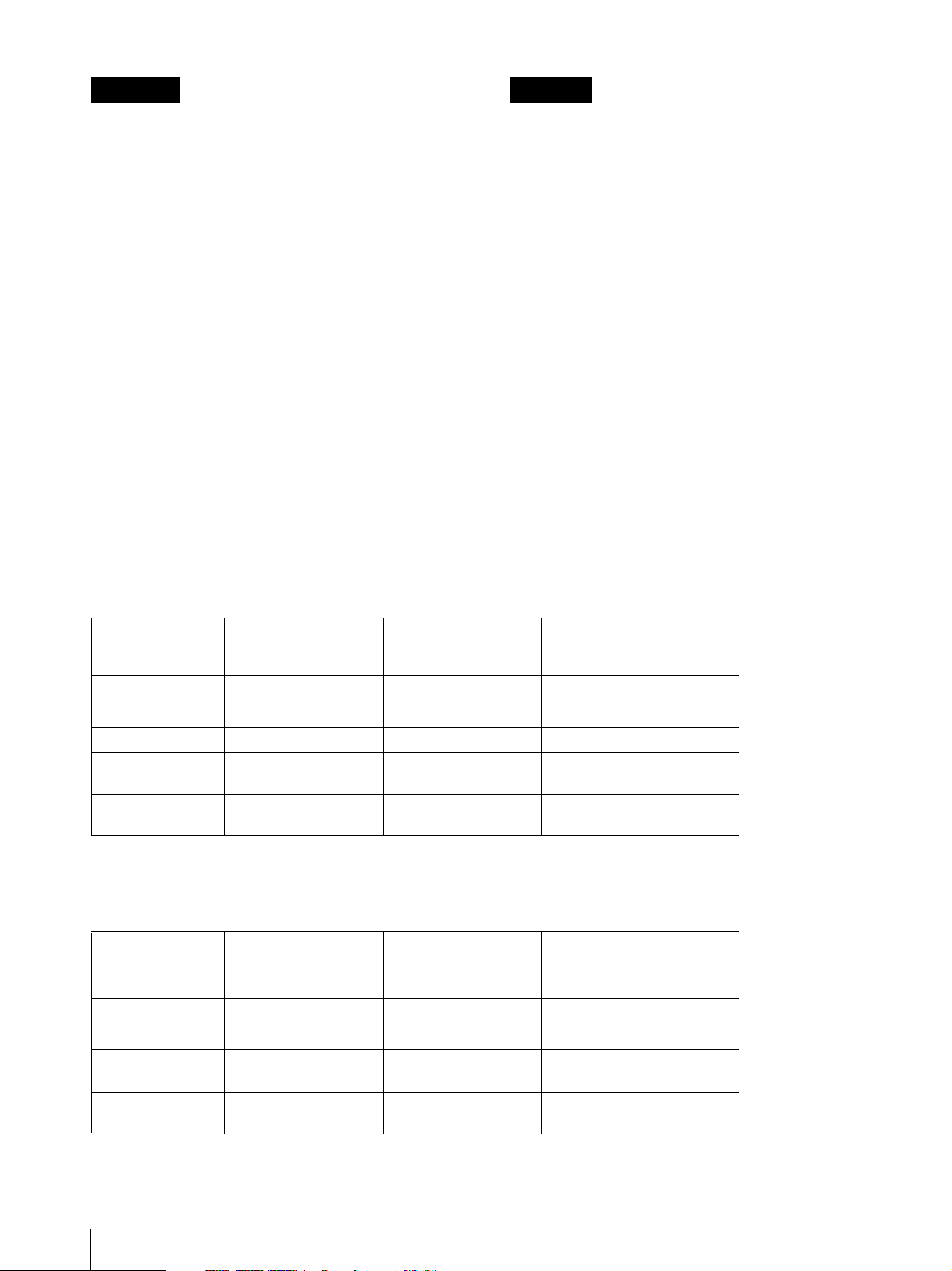
Warning on power connection
Use a proper power cord for your local power supply.
The United States,
Canada
Plug type VM0233 COX-07/636
Female end VM0089 COX-02/VM0310B VM0303B
Cord type SVT H05VV-F CEE(13)53rd (O, C)
Rated Voltage &
Current
Safety approval UL/CSA VDE VDE
10A/125V 10A/250V 10A/250V
Continental Europe UK, Ireland, Australia,
New Zealand
_ 1)
1) Use an appropriate rating plug which is applied to local regulations.
2
Page 3

The shielded interface cable recommended in this
manual must be used with this equipment in order to
comply with the limits for a digital device pursuant to
Subpart B of Part 15 of FCC Rules.
Attention-when the product is installed in Rack:
1.Prevention against overloading of branch
circuit
When this product is installed in a rack and is supplied
power from an outlet on the rack, please make sure that
the rack does not overload the supply circuit.
2.Providing protective earth
When this product is installed in a rack and is supplied
power from an outlet on the rack, please confirm that the
outlet is provided with a suitable protective earth
connection.
3.Internal air ambient temperature of the rack
When this product is installed in a rack, please make
sure that the internal air ambient temperature of the rack
is within the specified limit of this product.
4.Prevention against achieving hazardous
condition due to uneven mechanical loading
When this product is installed in a rack, please make
sure that the rack does not achieve hazardous condition
due to uneven mechanical loading.
5.Install the equipment while taking the
operating temperature of the equipment into
consideration
Please ensure the amount of air flow required for safe
operation of this product.
For the operating temperature of the equipment, refer to
the specifications of the Operation Manual.
Important Safety Instructions
• Read these instructions.
• Keep these instructions.
• Heed all warnings.
• Follow all instructions.
• Do not use this apparatus near water.
• Clean only with dry cloth.
• Do not block any ventilation openings. Install in
accordance with the manufacturer's instructions.
• Do not install near any heat sources such as radiators,
heat registers, stoves, or other apparatus (including
amplifiers) that produce heat.
• Do not defeat the safety purpose of the polarized or
grounding-type plug. A polarized plug has two blades
with one wider than the other. A grounding type plug
has two blades and a third grounding prong. The wide
blade or the third prong are provided for your safety.
If the provided plug does not fit into your outlet,
consult an electrician for replacement of the obsolete
outlet.
• Protect the power cord from being walked on or
pinched particularly at plugs, convenience
receptacles, and the point where they exit from the
apparatus.
• Only use attachments/accessories specified by the
manufacturer.
• Use only with the stand or bracket specified by the
manufacturer, or sold with the apparatus.
• Unplug this apparatus during lightning storms or
when unused for long periods of time.
• Refer all servicing to qualified service personnel.
Servicing is required when the apparatus has been
damaged in any way, such as power-supply cord or
plug is damaged, liquid has been spilled or objects
have fallen into the apparatus, the apparatus has been
exposed to rain or moisture, does not operate
normally, or has been dropped.
3
Page 4
Français Deutsch
AVERTISSEMENT
Afin d'éviter tout risque d'incendie ou
d'électrocution, ne pas exposer cet appareil à la
pluie ou à l'humidité.
Des courants de hautes tensions dangereuses
sont présents à l'intérieur de cet appareil. Ne
pas ouvrir le coffret. Se reporter à un personnel
qualifié uniquement.
Dans le cas d'une défaillance ou de nécessité d'entretien,
consulter un revendeur Sony autorisé.
Cet appareil contient des substances susceptibles de
causer une pllution de l'environnement si elles sont
éliminées de façon non conforme. Consultez votre
bureau local de préservation de l'environnement pour
savoir comment vous débarrasser de cet appareil.
AVERTISSEMENT
CET APPAREIL DOIT ETRE RELIE A LA TERRE.
WARNUNG
Um Feuergefahr und die Gefahr eines
elektrischen Schlages zu vermeiden, darf das
Gerät weder Regen noch Feuchtigkeit
ausgesetzt werden.
Im Inneren des Geräts liegt gefährliche
Hochspannung an. Öffnen Sie niemals das
Gehäuse, und überlassen Sie
Wartungsarbeiten stets nur einem Fachmann.
Sollten am Gerät Probleme auftreten oder eine Wartung
erforderlich werden, wenden Sie sich an einen
autorisierten Sony -Händler.
Dieses Gerät enthält Substanzen, die bei unsachgemäßer
Entsorgung die Umwelt belasten. Bitten wenden Sie
sich an unsere nächste Niederlassung oder an Ihr
Umweltschutzamt, wenn Sie das Gerät entsorgen
wollen.
WARNUNG
DIESES GERÄT MUSS GEERDET WERDEN.
Avertissement concernant le raccordement au secteur
Utilisez un cordon d'alimentation adapté à la tension secteur.
Etats-Unis, Canada Europe
continentale
Type de fiche VM0233 COX-07/636
Extrémité femelle VM0089 COX-02/VM0310B VM0303B
Type de cordon SVT H05VV-F CEE(13)53rd (O, C)
Intensité et tension
nominales
Certification de
sécurité
10A/125V 10A/250V 10A/250V
UL/CSA VDE VDE
Royaume-Uni, Irlande,
Australie, NouvelleZélande
_ 1)
1) Utilisez une fiche présentant les valeurs nominales appropriées et conforme à la réglementation locale en vigueur.
Warnhinweis zum Netzanschluss
Verwenden Sie ein für die Stromversorgung in Ihrem Land geeignetes Netzkabel.
USA, Kanada Kontinental-Europa Großbritannien, Irland,
Steckertyp VM0233 COX-07/636
Buchse VM0089 COX-02/VM0310B VM0303B
Kabeltyp SVT H05VV-F CEE(13)53rd (O, C)
Nennspannung &
Stromstärke
Sicherheitszertifizi
erung
10A/125V 10A/250V 10A/250V
UL/CSA VDE VDE
Australien, Neuseeland
_ 1)
1) Verwenden Sie einen geeigneten Netzstecker, der die örtlichen Bestimmungen erfüllt.
4
Page 5

Español Italiano
ADVERTENCIA
ATTENZIONE
Per evitare incendi o cortocircuiti,
Para evitar incendios o el riesgo de
electrocución, no exponga la unidad a la lluvia
ni a la humedad.
Dentro de la unidad existen altas tensiones
peligrosas. No la abra. En caso de avería,
solicite los servicios de personal cualificado.
En caso de mal funcionamiento o cuando sea necesario
el servicio de mantenimiento, consulte a su proveedor
l'apparecchio non deve essere esposto alla
pioggia o all'umidità.
All'interno del televisore sono presenti tensioni
pericolosamente alte. Non aprire
l'apparecchio. Per le riparazioni, rivolgersi
esclusivamente a personale specializzato.
Nel caso di malfunzionamenti o di necessarie
riparazioni dell'apparecchio, consultare un rivenditore
autorizzato Sony.
Sony.
Questo apparecchio contiene sostanze che possono
Esta unidad contiene sustancias que pueden contaminar
el medio ambiente si no se desecha adecuadamente.
Póngase en contacto con nuestro departamento de
representatión más próximo o con el departamento local
de medio ambiente cuando vaya a desechar esta unidad.
ADVERTENCIA
ESTE APARATO DEBE CONECTARSE A TIERRA.
inquinare l'amibiente se non vengono smaltite con le
dovute cautele. Per informazioni sulle normative in caso
di smaltimento di questo apparecchio, si prega di
contattare il nostro rappresentatnte locale o il centro di
informazioni ambientali di zona.
AVVERTENZA
QUESTO APPARECCHIO DEVE ESSERE
COLLEGATO A MASSA.
Advertencia sobre la conexión de alimentación
Utilice un cable de alimentación adecuado al suministro eléctrico loca.
Estados Unidos y
Canadá
Tipo de enchufe VM0233 COX-07/636
Extremo hembra VM0089 COX-02/VM0310B VM0303B
Tipo de cable SVT H05VV-F CEE(13)53rd (O, C)
Corriente y tensión
nominal
Aprobación de
seguridad
10A/125V 10A/250V 10A/250V
UL/CSA VDE VDE
Europa continental Reino Unido, Irlanda,
Australia y Nueva
Zelanda
_ 1)
1) Utilice un enchufe de valor nominal adecuado que cumpla con la normativa local.
Avvertenza sul collegamento dell'alimentazione
Utilizzare un cavo di alimentazione adeguato all'alimentazione del Paese in cui ci si trova.
Stati Uniti, Canada Europa
continentale
Tipo di spina VM0233 COX-07/636
Terminale
femmina
Tipo di cavo SVT H05VV-F CEE(13)53rd (O, C)
Tensione e corrente
nominale
Approvazione di
sicurezza
VM0089 COX-02/VM0310B VM0303B
10A/125V 10A/250V 10A/250V
UL/CSA VDE VDE
Regno Unito, Irlanda,
Australia, Nuova Zelanda
Giappone
_ 1)
1) Utilizzare una presa con voltaggio adeguato conforme alle normative locali.
5
Page 6
Pour les clients européens
Ce produit portant la marque CE est conforme à la fois
à la Directive sur la compatibilité électromagnétique
(EMC) (89/336/CEE) et à la Directive sur les basses
tensions (73/23/CEE) émises par la Commission de la
Communauté européenne.
La conformité à ces directives implique la conformité
aux normes européennes suivantes:
• EN60065: Sécurité des produits
• EN55103-1: Interférences électromagnétiques
(émission)
• EN55103-2: Sensibilité électromagnétique
(immunité)
Ce produit est prévu pour être utilisé dans les
environnements électromagnétiques suivants:
E1 (résidentiel), E2 (commercial et industrie légère), E3
(urbain extérieur) et E4 (environnement EMC contrôlé
ex. studio de télévision).
Für Kunden in Europa
Dieses Produkt besitzt die CE-Kennzeichnung Und
erfüllt die EMV-Richtlinie (89/336/EWG) sowie die
Niederspannungsrichtlinie (73/23/EWG) der EGKommission.
Angewandte Normen:
• EN60065: Sicherheitsbestimmungen
• EN55103-1: Elektromagnetische Verträglichkeit
(Störaussendung)
• EN55103-2: Elektromagnetische Verträglichkeit
(Störfestigkeit)
Dieses Produkt ist für den Einsatz unter folgenden
elektromagnetischen Bedingungen ausgelegt:
E1 (Wohnbereich), E2 (kommerzieller und in
beschränktem Maße industrieller Bereich), E3
(Stadtbereich im Freien) und E4 (kontrollierter EMVBereich, z. B. Fernsehstudio).
Para los usuarios en Europa
Este producto con la marca CE cumple con las
Directivas EMC (89/336/CEE) y de Baja Tensión (73/
23/CEE) emitidas por la Comisión de la Comunidad
Europea.
El cumplimiento de estas directivas implica la
conformidad con los siguientes estándares europeos:
• EN60065: Seguridad del producto
• EN55103-1: Interferencias electromagnéticas
(Emisión)
• EN55103-2: Susceptibilidad electromagnética
(Inmunidad)
Este producto está diseñado para utilizarse en los
siguientes entornos electromagnéticos:
E1 (residencial), E2 (comercial e industria ligera), E3
(exteriores urbanos) y E4 (entorno de EMC controlada,
ej. estudio de TV).
Per i clienti in Europa
Questo prodotto recante il marchio CE è conforme sia
alla direttiva sulla compatibilità elettromagnetica
(EMC) (89/336/CEE) che alla direttiva sulle basse
tensioni (73/23/CEE) emesse dalla Commissione della
Comunità Europea.
La conformità a queste direttive implica la conformità
alle seguenti normative europee:
• EN60065: Sicurezza dei prodotti
• EN55103-1: Interferenza elettromagnetica (Emissione)
• EN55103-2: Sensibilità ai disturbi elettromagnetici
(Immunità)
Il presente prodotto è stato progettato per l’impiego in
uno o più dei seguenti ambienti elettromagnetici:
E1 (residenziale), E2 (commerciale e di industria
leggera), E3 (esterni urbani) e E4 (ambiente controllato
EMC, ad esempio uno studio televisivo).
6
Page 7
7
Page 8

Table of Contents
Precaution .............................................................. 9
On Safety ............................................................ 9
On Installation .................................................... 9
Handling the LCD Screen .................................. 9
About the Fluorescent Tube ............................... 9
On Cleaning ....................................................... 9
On Repacking ..................................................... 9
On Mounting on a Rack ................................... 10
On Fan Error .................................................... 10
Features ................................................................ 10
Location and Function of Parts and Controls .. 12
Front Panel ....................................................... 12
Input Signals and Adjustable/Setting Items ..... 14
Rear Panel ........................................................ 15
Installing to the Rack .......................................... 17
Connecting the AC Power Cord ......................... 18
Attaching the Input Adaptor .............................. 18
Selecting the Default Settings ............................. 19
Selecting the Menu Language ............................ 20
Using the Menu .................................................... 21
Adjustment Using the Menus ............................. 22
Items ................................................................. 22
Adjusting and Changing the Settings ............... 23
STATUS menu............................................. 23
COLOR TEMP/BAL menu ......................... 23
USER CONTROL menu.............................. 23
USER CONFIG menu.................................. 24
REMOTE PARALLEL menu...................... 25
KEY INHIBIT menu.................................... 25
Troubleshooting ................................................... 26
Specifications ....................................................... 26
Dimensions ........................................................... 29
LMD-1410/1420 .......................................... 29
LMD-2010/2020 .......................................... 30
8
Page 9

Precaution
On Safety
• If a still picture is displayed for a long time, a residual
image may appear. The residual image will eventually
disappear.
• The screen and the cabinet become warm during
operation. This is not a malfunction.
• Operate the unit only with a power source as specified
in the “Specifications” section.
• A nameplate indicating operating voltage, power
consumption, etc., is located on the rear panel.
• Should any solid object or liquid fall into the cabinet,
unplug the unit and have it checked by qualified
personnel before operating it any further.
• Do not drop or place heavy objects on the power cord.
If the power cord is damaged, turn off the power
immediately. It is dangerous to use the unit with a
damaged power cord.
• Unplug the unit from the wall outlet if it is not to be
used for several days or more.
• Disconnect the power cord from the AC outlet by
grasping the plug, not by pulling the cord.
• The socket-outlet shall be installed near the equipment
and shall be easily accessible.
On Installation
• Allow adequate air circulation to prevent internal heat
build-up.
Do not place the unit on surfaces (rugs, blankets, etc.)
or near materials (curtains, draperies) that may block
the ventilation holes.
• Do not install the unit in a location near heat sources
such as radiators or air ducts, or in a place subject to
direct sunlight, excessive dust, mechanical vibration
or shock.
Handling the LCD Screen
• Bright or dark points of lights (red, blue or green) may
appear on the LCD screen. This is not a malfunction.
The LCD screen is made with high-precision
technology with more than 99.99 % of the picture
elements intact. However, some picture elements may
not appear intermittently.
• Do not leave the LCD screen facing the sun as it can
damage the LCD screen. Take care when you place
the unit by a window.
• Do not push or scratch the LCD monitor’s screen. Do
not place a heavy object on the LCD monitor’s screen.
This may cause the screen to lose uniformity.
• If the unit is used in a cold place, horizontal lines or a
residual image may appear on the screen. This is not
a malfunction. When the monitor becomes warm, the
screen returns to normal.
About the Fluorescent Tube
A specially designed fluorescent tube is installed as the
lighting apparatus for this unit. If the LCD screen
becomes dark, unstable or does not turn on, consult your
Sony dealer.
On Cleaning
Before cleaning
Be sure to disconnect the AC power cord from the AC
outlet.
On cleaning the monitor screen
The monitor screen surface is especially treated to
reduce reflection of light.
As incorrect maintenance may impair the performance
of the monitor, take care with respect to the following:
• Wipe the screen gently with a soft cloth such as a
cleaning cloth or glass cleaning cloth.
• Stubborn stains may be removed with a soft cloth such
as a cleaning cloth or glass cleaning cloth lightly
dampened with water.
• Never use solvent such as alcohol, benzene or thinner,
or acid, alkaline or abrasive detergent, or chemical
cleaning cloth, as they will damage the screen surface.
On cleaning the cabinet
• Clean the cabinet gently with a soft dry cloth.
Stubborn stains may be removed with a cloth lightly
dampened with mild detergent solution, followed by
wiping with a soft dry cloth.
• Use of alcohol, benzene, thinner or insecticide may
damage the finish of the cabinet or remove the
indications on the cabinet. Do not use these chemicals.
• If you rub on the cabinet with a stained cloth, the
cabinet may be scratched.
• If the cabinet is in contact with a rubber or vinyl resin
product for a long period of time, the finish of the
cabinet may deteriorate or the coating may come off.
On Repacking
Do not throw away the carton and packing materials.
They make an ideal container which to transport the
unit.
Precaution
9
Page 10

On Mounting on a Rack
Leave 1U space empty above and below the monitor to
ensure adequate air circulation or install a fan to
maintain the monitor’s performance.
If you have any questions about this unit, contact your
authorized Sony dealer.
On Fan Error
The fan for cooling the unit is built in. When the “FAN
ERROR” message is displayed, turn off the power and
contact an authorized Sony dealer.
About this manual
The instructions in this manual are for the following
four models:
•LMD-1410
•LMD-1420
•LMD-2010
•LMD-2020
The illustration of LMD-1420 is used for the
explanations.
Any differences in specifications are clearly indicated
in the text.
Features
The LMD-1410 and the LMD-1420 are a 14-type, the
LMD-2010 and the LMD-2020 are a 20-type LCD
monitor.
High brightness LCD panel
Because of the monitor’s high brightness, high contrast,
high speed response, and wide viewing angle
technology, it can be used under various lighting
conditions.
Rack mount monitors
The LMD-1410/1420 can be installed in a standard 19inch rack using an optional rack mounting bracket MB526 and the LMD-2010/2020 can be installed using MB-
527. This is essential when space is paramount in
crowded OB vehicles.
Monitor stand with tilt function
As the stand with tilt function is euipped for the monitor,
you can use it easily on the desk top. When you mount
the monitor to the rack, remove the stand.
Lightweight, thin design
The lightweight, thin design reduces the load for an OB
vehicle and the space needed for installation.
3-color tally lamp (LMD-1420/2020)
The tally lamp lights in red, green or amber to monitor
each input picture and check the on-air mode.
Two color system available
The monitor can display NTSC and PAL signals by
connecting this unit. The appropriate color system is
selected automatically.
Blue only mode (LMD-1420/2020)
In the blue only mode, an apparent monochrome display
is obtained with all three of the R/G/B cathodes driven
with a blue signal. This facilitates color saturation and
phase adjustments and observation of VCR noise.
Analog RGB/component input connectors
Analog RGB or component signals from video
equipment can be input through these connectors.
Y/C input connectors
The video signal, split into the luminance signal (Y) and
the chrominance signal (C), can be input through this
connector.
SDI optional input (LMD-1420/2020)
SDI signals can be available when input adaptor BKM320D (optional) is attached.
10
Features
Page 11

External sync input (LMD-1420/2020)
When the EXT SYNC button is in the on position, the
unit can be operated on the sync signal supplied from an
external sync generator.
Automatic termination (connector with
mark only)
The input connector is terminated internally at 75 ohms
when nothing has been connected to the output
connector. If a cable is connected to the output
connector, the internal terminal is automatically released
and the signals input to the input connector are output to
the output connector (loop-through).
Select color temperature and gamma mode
You can select the color temperature from among two
(high and low) settings and gamma mode from among
five settings. You can also adjust the color temperature
to the appropriate setting.
Aspect setting
You can set the monitor to 4:3 or 16:9 display mode
according to the input video signal.
Various markers (LMD-1420/2020)
Displays frame boundaries such as the center marker,
safe area marker, etc. and supports the various film
aspect ratios.
Scan setting
You can set the display size to -3% under scan or 5%
over scan mode.
On-screen menus
You can set the appropriate settings according to the
connected system by using the on-screen menus.
Key inhibit function
You can inhibit a key, function to prevent misoperation.
Select language display
You can select from seven display languages English,
French, German, Spanish, Italian, Japanese and
Chinese.
External remote control function
You can directly select the input signal, aspect, etc., by
operating the equipment connected to the PARALLEL
REMOTE terminal.
Features
11
Page 12

Location and Function of Parts and Controls
Front Panel
LMD-1420/2020
1
LINE A LINE B SDI SCAN ASPECT
qf
LMD-1410/2010
EXT
RGB/
LINE A LINE B SDI SCAN ASPECT
COMPONENT
qd
qs qa 0 9 8 7 6 5 4 3 2
RESET
MENU VOLUME POWER
KEY
INHIBIT
ENTER
RGB/
LINE A LINE B SCAN
COMPONENT
EXT
BLUE
RGB/
SYNC
ONLY
COMPONENT
BLUE
SYNC
ONLY
RESET
RESET
MENU VOLUME POWER
ENTER
MENU VOLUME POWER
ENTER
INHIBIT
INHIBIT
KEY
KEY
qdqfqs qa 7 5 4 3 2
12
RGB/
LINE A LINE B SCAN
COMPONENT
RESET
MENU VOLUME POWER
ENTER
Location and Function of Parts and Controls
KEY
INHIBIT
Page 13

a Tally lamp (LMD-1420/2020)
You can check the status of the monitor by the color of
the tally lamp.
The tally lamp lights in red, green or amber according to
the input signals.
b POWER switch and indicator
Press to turn on the power. The indicator turns on. Press
again to turn off the power.
c KEY INHIBIT indicator
When the key inhibit function works, the indicator
lights.
For the key inhibit function, refer to “KEY INHIBIT
menu” on page 25.
j SDI button
Press to monitor the signal from the OPTION IN
connector.
k RGB/COMPONENT button
Press to monitor the signal through the RGB/
COMPONENT input connectors.
l LINE B button
Press to monitor the signal through the LINE B input
connectors.
m LINE A button
Press to monitor the signal through the LINE A input
connectors.
d VOLUME buttons
Press the + button to increase the volume or the – button
to decrease it.
e Menu operation buttons
Displays or sets the on-screen menu.
M/m/</, (arrow) buttons
Select the menu or make various adjustments.
MENU button
Press to display the on-screen menu.
Press again to clear the menu.
RESET button
Resets the value of an item back to the previous
value. This button functions when the menu item is
adjusted (displayed) on the screen.
ENTER button
Press to confirm a selected item on the menu.
f ASPECT select button
Sets the aspect ratio of the picture, 4:3 or 16:9.
n Speakers
The audio signal which is selected by the input select
button on the front panel is output.
g SCAN select button
You can change the scan size of the picture. When you
press the button, the scan size is changed to normal (5%
over scan), under (-3% under scan) or ZOOM (LMD1420/2020 only) set on the menu (see page 25).
h BLUE ONLY button
Press this button to eliminate the red and green signals.
Only blue signal is displayed as an apparent
monochrome picture on the screen. This facilitates
“chroma” and “phase” adjustments and observation of
VCR noise.
i EXT SYNC (external sync) button
Press to operate the unit on an external sync signal
through the EXT SYNC IN connector.
The EXT SYNC button works when the component/
RGB signals are input.
Location and Function of Parts and Controls
13
Page 14

Input Signals and Adjustable/ Setting Items
Input signal
Item Video, Y/C B & W Component RGB SDI (LMD-1420/2020)
D1
CONTRAST
BRIGHT
CHROMA
PHASE
APERTURE
COLOR TEMP
COMP LEVEL
NTSC SETUP
GAMMA
SCAN
ASPECT
MARKER (LMD-1420/2020)
BLUE ONLY (LMD-1420/2020)
*
aaaa a
aaaa a
a
a (NTSC)
aaa
aaaa a
×
××× ×
××
a (NTSC) a
(480/60I)
aaaa a
aaaa a
aaaa a
aaaa a
a
×
a
a
×
×
××
a
a
×× ×
aa a
* When a component signal (480/60I) is input, this can
be switchable.
a : Adjustable/can be set
× : Not adjustable/cannot be set
14
Location and Function of Parts and Controls
Page 15

Rear Panel
LMD-1420/2020
21345678
LMD-1410/2010
LINE A
IN OUT
LINE A
PARALLEL REMOTE RGB/COMPONENT
LINE B
IN OUT
IN OUT
VIDEO
IN OUT
AUDIO
VIDEO
IN OUT
AUDIO
AC IN
IN OUT
IN OUT
IN OUT
OPTION
AUDIO IN
G/Y
B/P
R/P
OPTION IN
EXT
IN OUT
B
SYNC
IN OUT
AUDIO
R
AC IN
VIDEO
IN OUT
AUDIO
PARALLEL REMOTE RGB/COMPONENT
LINE B
IN OUT
VIDEO
IN OUT
AUDIO
IN OUT
G/Y
IN OUT
B/P
B
IN OUT
R/P
R
OPTION
AUDIO IN
EXT
IN OUT
SYNC
IN OUT
AUDIO
OPTION IN
45678
LINE A
LINE A
PARALLEL REMOTE RGB/COMPONENT
IN OUT
G/Y
LINE B
IN OUT
IN OUT
VIDEO
IN OUT
AUDIO
IN OUT
IN OUT
B/P
B
IN OUT
AUDIO
R/P
R
VIDEO
AC IN
IN OUT
AUDIO
AC IN
IN OUT
IN OUT
PARALLEL REMOTE RGB/COMPONENT
VIDEO
AUDIO
LINE B
IN OUT
VIDEO
IN OUT
AUDIO
IN OUT
G/Y
IN OUT
B/P
B
IN OUT
R/P
R
OPTION
AUDIOINOPTION
EXT
IN OUT
SYNC
IN OUT
AUDIO
IN
a OPTION IN connector (D-sub 9-pin, female)
(LMD-1420/2020)
When optional Sony input adaptor BKM-320D is
connected, SDI signals are input.
Press the SDI button to select the signal.
Note
Do not install the equipment other than BKM-320D.
It causes to damage the unit or the equipment.
b OPTION AUDIO IN connector (LMD-1420/
2020)
If the BKM-320D is installed in the OPTION IN
connector, input an audio signal into this connector.
Press the SDI button to monitor the audio signal.
c EXT SYNC IN/OUT (external sync) connectors
(BNC) (LMD-1420/2020)
Press the EXT SYNC button to use the sync signal
through this connector.
IN connector
When this unit operates on an external sync signal,
connect the reference signal from a sync generator
to this connector.
Note
When inputting a video signal with the jitters, etc.
the picture may be disturbed. We recommend using
the TBC (time base corrector).
OUT connector
Loop-through output of the IN connector. Connect
to the external sync input of video equipment to be
synchronized with this unit.
When the cable is connected to this connector, the
75-ohm termination of the input is automatically
released, and the signal input to the IN connector is
output from this connector.
Location and Function of Parts and Controls
15
Page 16

d RGB/COMPONENT connectors
Analog RGB signal or component (Y, P
B, PR) signal
input connectors and their loop-through output
connectors.
Press the RGB/COMPONENT button on the front panel
to monitor the signal input through these connectors.
G/Y, B/P
B, R/PR IN/OUT (BNC)
These are the input/output connectors for an analog
RGB and a component (Y, P
B, PR) signal. Unless
an external sync signal is input, the monitor is
synchronized with the sync signal contained in the
G/Y signal.
AUDIO IN/OUT (RCA pin)
When using an analog RGB or a component signal
as a video signal, use these jacks for the input/
output of an audio signal. Connect them to the
audio input/output jacks on equipment such as a
VCR.
e PARALLEL REMOTE terminal (modular
connector)
Forms a parallel switch and controls the monitor
externally.
For safety, do not connect the connector for peripheral
device wiring that might have excessive voltage to this
modular connector.
Y/C IN/OUT (4-pin mini-DIN)
These are the input/output connectors for a Y/C
separate signal. Connect them to the Y/C separate
input/output connectors on equipment such as a
VCR, video camera, or another monitor.
VIDEO IN/OUT (BNC)
These are the input/output connectors for a
composite video signal. Connect them to the
composite video input/output connectors on
equipment such as a VCR, video camera, or another
monitor.
AUDIO IN/OUT (RCA pin)
These are the input/output jacks for an audio signal.
Connect them to the audio input/output jacks on
equipment such as a VCR.
h AC IN socket
Connect the supplied AC power cord.
For details on the pin assignment and factory setting
function assigned to each pin, see page 28.
f LINE B connectors
Line input connectors for composite video and audio
signals and their loop-through output connectors.
Press the LINE B button on the front panel to monitor
the signal input through these connectors.
VIDEO IN/OUT (BNC)
These are the input/output connectors for a
composite video signal. Connect them to the
composite video input/output connectors on
equipment such as a VCR, video camera, or another
monitor.
AUDIO IN/OUT (RCA pin)
These are the input/output jacks for an audio signal.
Connect them to the audio input/output jacks on
equipment such as a VCR.
g LINE A connectors
Line input connectors for Y/C separate, composite video
and audio signals and their loop-through output
connectors.
Press the LINE A button on the front panel to monitor
the input signal through these connectors.
If you input signals to both Y/C IN and VIDEO IN, the
signal input to the Y/C IN is selected.
16
Location and Function of Parts and Controls
Page 17

Installing to the Rack
1
Remove the screws (4) to remove the stand.
LMD-2010/2020
LINE A
PARALLEL REMOTE RGB/COMPONENT
IN OUT
VIDEO
AC IN
IN OUT
AUDIO
2
Attach the unit to the rack after attaching the
OPTION
AUDIO IN
IN OUT
G/Y
LINE B
IN OUT
VIDEO
IN OUT
AUDIO
OPTION IN
EXT
IN OUT
IN OUT
B/P
B
SYNC
IN OUT
IN OUT
AUDIO
R/P
R
mounting bracket.
LMD-1410/1420
L
I
N
E
A
L
I
N
E
R
G
B
B
/
C
O
M
P
O
N
E
N
T
S
D
E
I
X
T
S
Y
N
B
C
L
U
E
O
N
L
Y
S
C
A
N
A
S
P
E
C
T
M
E
N
U
R
E
S
E
T
V
O
L
U
M
E
E
N
T
E
R
K
E
Y
I
N
H
I
B
I
L
I
N
E
A
L
I
N
E
R
G
B
B
/
C
O
M
P
O
N
E
N
T
S
D
E
I
X
T
S
Y
N
B
C
L
U
E
O
N
L
Y
S
C
A
N
A
S
P
E
C
T
M
E
N
U
R
E
S
E
T
V
O
L
U
M
E
E
N
T
E
R
P
O
W
E
R
K
E
Y
I
N
H
I
B
I
T
P
O
W
E
R
T
Installing to the Rack
17
Page 18

Connecting the AC
Attaching the Input
Power Cord
Connect the supplied AC power cord as illustrated.
1
Plug the AC power cord into the AC IN socket on
the rear panel. Then, attach the AC plug holder
(supplied) to the AC power cord.
AC IN socket
L
I
N
E
A
IN O
U
T
VIDEO
AC
IN
IN O
U
T
AUDIO
AC power cord
AC plug holder (Supplied)
Adaptor
LMD-1420/2020
Before attaching the input adaptor, disconnect the power
cord.
Note
Do not install the equipment other than BKM-320D.
It causes to damage the unit or the equipment.
2
Slide the AC plug holder over the cord until it locks.
L
IN
E
A
I
N
O
U
T
VIDEO
AC IN
I
N
O
U
T
AUDIO
To remove the AC power cord
Pull out the AC plug holder while pressing the lock
levers.
18
Connecting the AC Power Cord / Attaching the Input Adaptor
Page 19

Selecting the Default Settings
When you turn on the unit for the first time after
purchasing it, select the area where you intend to use this
unit from among the options.
The default setting values for each area
3
1
5
4
3
3
1NORTH AMERICA Low BETA7.5 7.5
2LATIN AMERICA
PAL&PAL-N AREA
NTSC&PAL-M AREA OTHER AREA Low BETA7.5 7.5
ARGENTINA Low SMPTE 0
PARAGUAY Low SMPTE 0
URUGUAY Low SMPTE 0
3AFRICA AUSTRALASIA
EUROPE MIDDLE-EAST
4ASIA EXCEPT JAPAN
NTSC AREA Low BETA7.5 7.5
PAL AREA Low SMPTE 0
5JAPAN High SMPTE 0
2
COLOR
TEMP
COMP
LEVEL
Low SMPTE 0
SETUP
NTSC
RGB/
LINE A LINE B SDI SCAN ASPECT
COMPONENT
RESET
EXT
BLUE
SYNC
ONLY
MENU VOLUME POWER
ENTER
RESET
MENU VOLUME POWER
KEY
INHIBIT
ENTER
KEY
INHIBIT
2~3 1
1
Press the POWER switch.
The power is turned on and the SELECT SETTING
screen appears.
1North America
S E L E C T S E T T I N G
x N O R T H A M E R I C A
• L A T I N A M E R I C A
• A F R I C A A U S T R A L A S I A
E U R O P E M I D D L E - E A S T
• A S I A E X C E P T J A P A N
• J A P A N
2
Press the M or m button to select the area where you
intend to use the unit and press the , or ENTER
button.
If you select either LATIN AMERICA or ASIA
EXCEPT JAPAN, one of the following screens
appears.
2Latin America
3Africa Australia/New
Zealand, Europe, Middle
East, Russia
4Asia Except Japan
5Japan
2 If LATIN AMERICA is selected:
PAL&PAL-N area
L A T I N A M E R I C A
x P A L & P A L - N A R E A
A R G E N T I N A
P A R A G U A Y
U R U G U A Y
• N T S C & P A L - M A R E A
O T H E R A R E A
Argentina
Paraguay
Uruguay
NTSC&PAL-M area
Other area
Selecting the Default Settings
19
Page 20

4 If ASIA EXCEPT JAPAN is selected:
Customers who will use this unit in the shaded
areas shown in the map below should select NTSC
AREA.
Other customers should select PAL AREA.
Selecting the Menu Language
You can select one of seven languages (English, French,
German, Spanish, Italian, Japanese, Chinese) for
displaying the menu and other on-screen displays.
The current settings are displayed in place of the x
marks on the illustrations of the menu screen.
A S I A E X C E P T J A P A N
x N T S C A R E A
• P A L A R E A
3
Press the M or m button to narrow the area further
NTSC area
PAL area
and then press the , or ENTER button.
The SELECT SETTING screen disappears and the
menu item settings suitable for the selected area are
applied.
Note
When you have selected the wrong area, set the
following items using the menu.
COLOR TEMP (on page 23)
COMP LEVEL(on page 24)
NTSC SETUP (on page 24)
See “The default setting values for each area” (on
page 19) on the setting value.
RGB/
LINE A LINE B SDI SCAN ASPECT
COMPONENT
RESET
EXT
BLUE
SYNC
ONLY
MENU VOLUME POWER
ENTER
RESET
MENU VOLUME POWER
KEY
INHIBIT
ENTER
KEY
INHIBIT
3~5 2 1
1
Press the POWER switch to turn on the unit.
2
Press the MENU button.
The menu appears.
The menu presently selected is shown as a yellow
button.
STATUS (1/2) Rr
FORMAT xxxxx
xxxxxxxx
COLOR TEMP xxxx
GAMMA x
COMP LEVEL xxxxx
NTSC SETUP xx
RGB/COMP SEL xxxx
SCAN MODE xxxx
20
Selecting the Menu Language
Page 21

3
Press the M or m button to select the following
menu, then press the , or ENTER button.
LMD-1410/2010: USER CONFIG (User
Configuration) menu
LMD-1420/2020: USER CONFIG 1/2 (User
Configuration 1/2) menu
The setting items (icons) in the selected menu are
displayed in yellow.
LMD-1410/2010
.
USER CONFIG
· RGB/COMP SEL xxxx
· COMP LEVEL xxxxx
· NTSC SETUP x
· GAMMA x
· FORMAT DISP xxxx
xLANGUAGE ENGLISH
· PIC DELAY MIN xxx
LMD-1420/2020
USER CONFIG (1/2) Rr
· RGB/COMP SEL xxxx
· COMP LEVEL xxxxx
· NTSC SETUP x
· GAMMA x
· FORMAT DISP xxxx
xLANGUAGE ENGLISH
Using the Menu
The unit is equipped with an on-screen menu for making
various adjustments and settings such as picture control,
input setting, set setting change, etc. You can also
change the menu language displayed in the on-screen
menu.
To change the menu language, see “Selecting the Menu
Language” on page 20 (GB).
The current settings are displayed in place of the x
marks on the illustrations of the menu screen.
RESET
MENU VOLUME POWER
KEY
INHIBIT
ENTER
EXT
BLUE
RGB/
SYNC
LINE A LINE B SDI SCAN ASPECT
ONLY
COMPONENT
4
Press the M or m button to select “LANGUAGE,”
then press the , or ENTER button.
The selected item is displayed in yellow.
5
Press the M or m button to select a language, then
press the ENTER button.
The menu changes to the selected language.
LMD-1410/2010
.
USER CONFIG
· RGB/COMP SEL xxxx
· COMP LEVEL xxxxx
· NTSC SETUP x
· GAMMA x
· FORMAT DISP xxxx
xLANGUAGE ENGLISH
· PIC DELAY MIN xxx
LMD-1420/2020
USER CONFIG (1/2) Rr
· RGB/COMP SEL xxxx
· COMP LEVEL xxxxx
· NTSC SETUP x
· GAMMA x
· FORMAT DISP xxxx
xLANGUAGE ENGLISH
To clear the menu
Press the MENU button.
The menu disappears automatically if a button is not
pressed for one minute.
RESET
MENU VOLUME POWER
ENTER
KEY
INHIBIT
2~4 1
1
Press the MENU button.
The menu appears.
The menu presently selected is shown as a yellow
button.
STATUS (1/2) Rr
FORMAT xxxxxxxxx
xxxxxxxx
COLOR TEMP xxx
GAMMA x
COMP LEVEL xxxxx
NTSC SETUP x
RGB/COMP SEL xxxx
SCAN MODE xxxx
2
Use the M or m button to select a menu, then press
the , or ENTER button.
The menu icon presently selected is shown in
yellow and setting items are displayed.
LMD-1410/2010
.
USER CONFIG
· RGB/COMP SEL xxxx
· COMP LEVEL xxxxx
· NTSC SETUP x
· GAMMA x
· FORMAT DISP xxxx
xLANGUAGE ENGLISH
· PIC DELAY MIN xxx
Using the Menu
21
Page 22

LMD-1420/2020
USER CONFIG (1/2) Rr
· RGB/COMP SEL xxxx
· COMP LEVEL xxxxx
· NTSC SETUP x
· GAMMA x
· FORMAT DISP xxxx
xLANGUAGE ENGLISH
3
Select an item.
Use the M or m button to select the item, then press
the , or ENTER button.
The item to be changed is displayed in yellow.
Note
If the menu consists of multiple pages, press M or
m to go to the desired menu page.
4
Make the setting or adjustment on an item.
When changing the adjustment level:
To increase the number, press the M button.
To decrease the number, press the m button.
Press the ENTER button to confirm the number,
then restore the original screen.
When changing the setting:
Press the M or m button to change the setting.
Press the ENTER button to confirm the setting.
Notes
Adjustment Using the Menus
Items
The screen menu of this monitor consists of the
following items.
STATUS (the items indicate the
current settings.)
FORMAT
COLOR TEMP
GAMMA
COMP LEVEL
NTSC SETUP
RGB/COMP SEL
SCAN MODE
DISPLAY
OPTION
COLOR TEMP/BAL
COLOR TEMP
MANUAL ADJ
• An item displayed in blue cannot be accessed.
You can access the item if it is displayed in white.
• If the key inhibit has been turned on, all items are
displayed in blue. To change any of the items,
turn the key inhibit to OFF first.
For details on the key inhibit, see page 25.
To clear the menu
Press the MENU button.
The menu disappears automatically if a button is not
pressed for one minute.
About the memory of the settings
The settings are automatically stored in the monitor
memory.
To reset items that have been adjusted
Pressing the RESET button while you are adjusting any
of the menu items resets the menu item to the previous
setting.
USER CONTROL
CONTROL
USER CONFIG
RGB/COMP SEL
COMP LEVEL
NTSC SETUP
GAMMA
FORMAT DISP
LANGUAGE
MARKER (LMD-1420/2020 only)
CENTER MARKER (LMD-1420/2020 only)
SAFETY AREA (LMD-1420/2020 only)
MARKER LEVEL (LMD-1420/2020 only)
MARKER MAT (LMD-1420/2020 only)
SCAN (LMD-1420/2020 only)
PIC DELAY MIN
22
Adjustment Using the Menus
Page 23

REMOTE PARALLEL
1 PIN
2 PIN
3 PIN
4 PIN
6 PIN
7 PIN
8 PIN
KEY INHIBIT
KEY INHIBIT
COLOR TEMP/BAL menu
The COLOR TEMP/BAL menu is used for adjusting the
picture white balance.
You need to use the measurement instrument to adjust
the white balance.
Recommended: Konicaminolta color analyzer CA-210
COLOR TEMP/BAL
xCOLOR TEMP xxxx
MANUAL ADJ
· ADJUST GAIN···
· ADJUST BIAS···
· COPY FROM xxx
Adjusting and Changing the Settings
STATUS menu
The STATUS menu is used to display the current status
of the unit. The following items are displayed:
STATUS (1/2) Rr
FORMAT xxxxx
xxxxxxxx
COLOR TEMP xxxx
GAMMA x
COMP LEVEL xxxxx
NTSC SETUP xx
RGB/COMP SEL xxxx
SCAN MODE xxxx
STATUS (2/2) Rr
DISPLAY
LMD-1420 xxxxxxx
OPTION
BKM-320D
•Signal format
• Color temperature
• Gamma
• Component level
•NTSC setup
• RGB/COMP SEL
•Scan mode
•Display
•Option
Submenu Setting
COLOR TEMP Select the color temperature from
among HIGH, LOW and USER
setting.
MANUAL ADJ If you set the COLOR TEMP to
USER setting, the item displayed is
changed from blue to white, which
means you can adjust the color
temperature.
• ADJUST GAIN...: Adjusts the
color balance (GAIN).
• ADJUST BIAS...: Adjusts the
color balance (BIAS).
• COPY FROM: If you select
HIGH or LOW, the white
balance data for the selected
color temperature will be
copied in the user setting.
USER CONTROL menu
The USER CONTROL menu is used for adjusting the
picture.
Items that cannot be adjusted depending on the input
signal are displayed in blue.
USER CONTROL
CONTROL
xCONTRAST x
· BRIGHT x
· CHROMA x
· PHASE x
· APERTURE xxx
· ASPECT xxx
Adjustment Using the Menus
23
Page 24

Submenu Setting
CONTROL You can adjust the picture.
• CONTRAST: Adjusts the picture
contrast.
• BRIGHT: Adjusts the picture
brightness.
• CHROMA: Adjusts color intensity.
The higher the setting, the greater
the intensity. The lower the setting,
the lower the intensity.
• PHASE: Adjusts color tones. The
higher the setting, the more
greenish the picture. The lower the
setting, the more purplish the
picture.
• APERTURE: Adjusts the picture
sharpness. The higher the setting,
the sharper the picture.
For details of input signals and adjustable/
setting items, see page 14.
ASPECT (LMD1410/2010 only)
Sets the aspect ratio of the picture to 4:3 or
16:9.
USER CONFIG menu
You can select a language, etc.
Items that cannot be adjusted depending on the input
signal are displayed in blue.
LMD-1410/2010
.
USER CONFIG
x RGB/COMP SEL xxxx
· COMP LEVEL xxxxx
· NTSC SETUP x
· GAMMA x
· FORMAT DISP xxx
· LANGUAGE xxx
· PIC DELAY MIN xxx
LMD-1420/2020
USER CONFIG (1/2) Rr
x RGB/COMP SEL xxxx
· COMP LEVEL xxxxx
· NTSC SETUP x
· GAMMA x
· FORMAT DISP xxx
· LANGUAGE xxx
USER CONFIG (2/2) Rr
xMARKER xxx
· CENTER MARKER xxx
· SAFETY AREA xxx
· MARKER LEVEL x
· MARKER MAT xxx
· SCAN xxxx
· PIC DELAY MIN xxx
Submenu Setting
RGB/COMP SEL When a signal input via the RGB/
COMPONENT connector is being
monitored, based on the signal being
input, select RGB or COMP.
COMP LEVEL Select the component level from among
three modes.
• SMPTE for 100/0/100/0 signal
• BETA 0 for 100/0/75/0 signal
• BETA 7.5 for 100/7.5/75/7.5 signal
NTSC SETUP Select the NTSC setup level from two
modes.
The 7.5 setup level is used mainly in
North America. The 0 setup level is used
mainly in Japan.
GAMMA Selects the appropriate gamma mode.
You can select from among 5 settings.
When “3” is selected, the setting is
roughly same as the gamma mode of the
CRT (2.2).
FORMAT DISP Select the display mode of the signal
format.
• ON: The format is always displayed.
• OFF: The display is hidden.
• AUTO: The format is displayed for
about 10 seconds when the input
of the signal begins.
LANGUAGE You can select the menu or message
language from among seven languages.
• ENGLISH: English
• DEUTSCH: German
• FRANÇAIS: French
• ITALIANO: Italian
• ESPAÑOL: Spanish
• : Japanese
• : Chinese
MARKER When the frame of the film is displayed
on the screen, select the aspect ratio
according to the film.
• When 16:9 aspect ratio is selected
with the ASPECT button
You can select from among 4:3,
15:9, 14:9, 13:9 and OFF.
• When 4:3 aspect ratio is selected
with the ASPECT button
You can select from among 16:9
and OFF.
CENTER MARKER Select ON to display the center mark of
the picture and OFF not to display.
SAFETY AREA Select the safe area size for the aspect
ratio determined by the ASPECT button.
You can select from among OFF, 80%,
85%, 88%, 90% and 93%.
MARKER LEVEL Sets the luminance to display the
MARKER and SAFETY AREA.
When the setting is low, the marker is
displayed dark.
MARKER MAT Selects whether you put mat on the
outside of the marker display.
• OFF: No mat is put.
• HALF: Gray mat is put.
• BLACK: Black mat is put.
24
Adjustment Using the Menus
Page 25

Submenu Setting
SCAN Sets the scan size of the picture. Select
from “OFF” and “ZOOM” mode.
PIC DELAY MIN Selects to set the delay by the picture
NORMAL
SCAN (5 %
OVE RSCAN )
processing to the minimum level when
the signal is input.
• OFF: Mode for giving precedence to
the picture quality (recommended
mode). It takes longer than “ON”
for processing the picture.
• ON: The processing time is short. As
the line flicker is displayed in this
mode, it is available for checking
the line flicker of the telop work
and so on.
Input
4
3
9
16
• – – – (“– – –”: No function is assigned.)
•LINE A
•LINE B
•RGB/COMP
• 16:9
•4:3
• UNDER
• NORMAL
• ZOOM (LMD-1420/2020 only)
• TALLY R (LMD-1420/2020 only)
• TALLY G (LMD-1420/2020 only)
• EXT SYNC (LMD-1420/2020 only)
• BLUE ONLY (LMD-1420/2020 only)
• 16:9 MARKER (LMD-1420/2020 only)
• 15:9 MARKER (LMD-1420/2020 only)
• 14:9 MARKER (LMD-1420/2020 only)
• 13:9 MARKER (LMD-1420/2020 only)
• 4:3 MARKER (LMD-1420/2020 only)
• CENTER MARKER (LMD-1420/2020 only)
• SAFETY AREA 80% (LMD-1420/2020 only)
• SAFETY AREA 85% (LMD-1420/2020 only)
• SAFETY AREA 88% (LMD-1420/2020 only)
• SAFETY AREA 90% (LMD-1420/2020 only)
• SAFETY AREA 93% (LMD-1420/2020 only)
• SDI (LMD-1420/2020 only)
UNDER
SCAN
Output
ZOOM
4
3
–
16
9
REMOTE PARALLEL menu
Select the PARALLEL REMOTE connector pins for
which you want to change the function.
You can assign various functions to 1 to 4 pins and 6 to
8 pins. The following lists the functions you can assign
to the pins.
REMOTE PARALLEL
x1PIN xxxxx
· 2PIN xxxxx
· 3PIN xxxxxxx
· 4PIN xxxxxxx
· 6PIN xxxxxxxx
· 7PIN xxxxxxxxx
· 8PIN xxxx
If you use the PARALLEL REMOTE function, you
need to connect cables. For more details, see page 28.
KEY INHIBIT menu
KEY INHIBIT
xKEY INHIBIT xxx
You can lock the setting so that they cannot be changed
by an unauthorized user.
Select OFF or ON.
If you set ON, all items are displayed in blue, indicating
the items are locked.
Adjustment Using the Menus
25
Page 26

Troubleshooting
Specifications
This section may help you isolate the cause of a problem
and as a result, eliminate the need to contact technical
support.
• The display is colored in green or purple t Select
the correct input by pressing RGB/COMPONENT
button.
• The unit cannot be operated t The key protection
function works. Set the KEY INHIBIT setting to OFF
in the KEY INHIBITmenu.
Picture performance
LCD panel a-Si TFT Active Matrix
Picture size LMD-1410/1420: 14 type
283 × 212 × 354 mm (W/H/
Diagonal) (11
LMD-2010/2020: 20 type
408 × 306 × 510 mm (W/H/
Diagonal) (16
inches)
Resolution 640 × 480 dots (VGA)
Viewing angle 85°/85°/85°/85° (typical)
Scan Under –3 %
Normal 5 %
Aspect 4:3
Display color LMD-1410/1420: 16,200,000
LMD-2010/2020: 16,700,000
1
/4 × 83/8 ×14 inches)
1
/8 × 121/8 ×201/8
Input/output connectors
Input
LINE A input connectors
Y/C input 4-pin mini-DIN (1)
VIDEO input
BNC type (1), 1 Vp-p
synchronization
AUDIO input
RCA pin (1), –5 dBu 47 kilohms or
higher
LINE B input connectors
VIDEO input
BNC type (1), 1 Vp-p
synchronization
AUDIO input
RCA pin (1), –5 dBu 47 kilohms or
higher
RGB/COMPONENT input connectors BNC type (3)
RGB input 0.7 Vp-p
Component input
0.7 Vp-p
AUDIO input
RCA pin (1), –5 dBu 47 kilohms or
±3 dB, (Sync On Green, 0.3
Vp-p negative sync.)
±3 dB, (75 % chrominance
standard color bar signal)
higher
±3 dB, negative
±3 dB, negative
26
Troubleshooting / Specifications
Page 27

OPTION AUDIO input jacks (LMD-1420/2020)
RCA pin (2), –5 dBu 47 kilohms or
higher
External synchronized input (LMD-1420/2020)
BNC type (1), 0.3 to 4 Vp-p
negative polarity binary
PARALLEL REMOTE input terminal
Parallel remote
Modular connector 8-pin (1)
Output
LINE A output connectors
Y/C output 4-pin mini-DIN (1), Loop-through,
with 75 ohms automatic terminal
function
VIDEO output
BNC type (1), Loop-through, with 75
ohms automatic terminal function
AUDIO output
RCA pin (1), Loop-through
LINE B output connectors
VIDEO output
BNC type (1), Loop-through, with 75
ohms automatic terminal function
AUDIO output
RCA pin (1), Loop-through
RGB/COMPONENT output connectors
RGB/Component output
BNC type (3), Loop-through, with
75 ohms automatic terminal
function
AUDIO output
RCA pin (1), Loop-through
EXT SYNC output connector (LMD-1420/2020)
BNC type (1), Loop-through, with
75 ohms automatic terminal
function
Built-in speaker output
0.5 W (mono)
General
Power AC100 – 240 V, 50/60 Hz
Power consumption
LMD-1410: Maximum: approx. 48 W
1.2 A – 0.6 A
LMD-1420: Maximum: approx. 51 W
1.2 A – 0.6 A
LMD-2010: Maximum: approx. 84 W
1.2 A – 0.6 A
LMD-2020: Maximum: approx. 87 W
1.2 A – 0.6 A
Peak inrush current
(1) Power ON, current probe method:
90 A (LMD-1410/1420),
64 A (LMD-2010/2020)
(2) Hot switching inrush current,
measured in accordance with
European standard EN55103-1:
12 A (LMD-1410/1420/2010/2020)
Dimensions LMD-1410/1420: Approx. 343 × 354 ×
264 mm (not including the
projection parts)
5
(13
/8 × 14 ×101/2 inches)
(w/h/d)
LMD-2010/2020: Approx. 470× 441 ×
264 mm (not including the
projection parts)
5
(18
/8 × 173/8 × 101/2 inches)
(w/h/d)
Mass LMD-1410: Approx. 6.5 kg
(14 lb 5 oz)
LMD-1420: Approx. 6.8 kg
(14 lb 16 oz)
LMD-2010: Approx. 8.7 kg
(19 lb 3 oz)
LMD-2020: Approx. 9.2 kg
(20 lb 5 oz)
Operating conditions
Temperature0 °C to 35 °C (32 °F to 95 °F)
Recommended temperature
20 °C to 30 °C (68 °F to 86 °F)
Humidity 30% to 85% (no condensation)
Pressure 700 hPa to 1060 hPa
Storage and transport conditions
Temperature–10 °C to 40 °C (14 °F to 104 °F)
Humidity 0% to 90%
Pressure 700 hPa to 1060 hPa
Accessories supplied
AC power cord (1)
AC plug holder (1)
Operating Instructions (1)
CD-ROM (1)
Warranty Card (1)
Using the CD-ROM Manual (1)
Optional accessories
Rack mount bracket for 14 type
monitor MB-526
Rack mount bracket for 20 type
monitor MB-527
SDI input adaptor BKM-320D
Design and specifications are subject to change without
notice.
Specifications
27
Page 28

Pin assignment
PARALLEL REMOTE terminal
Modular connector
(8-pin)
1
8
Pin number Functions
1 Designating LINE A input signal
2 Designating LINE B input signal
3 Designate RGB/COMPONENT input signal
4 16:9
5 GND
6 4:3
7 Selecting under
8 Selecting normal
You can allocate functions using the REMOTE
PARALLEL menu (see page 25).
Wiring required to use the Remote Control
Connect the function you want to use with a Remote
Control to the Ground (Pin 5).
Video signal formats
The unit is applicable to the following signal formats.
Input
System Total lines Active lines Frame rate Scanning format Aspect ratio Signal standard
575/50I (PAL) 625 575 25 2:1 interlace 16:9/4:3 EBU N10
480/60I (NTSC) 525 483 30 2:1 interlace 16:9/4:3 SMPTE 253M
(PAL: ITU-R BT.624)
(NTSC: SMPTE 170M)
Output
System Effective picture size Frame rate Scanning format
575/50I (PAL) 640 × 480 50 Progressive
480/60I (NTSC) 640 × 480 60 Progressive
When an optional input adaptor is installed, the unit is applicable to the following signal formats.
When BKM-320D is installed
Input
System Signal standard BKM-320D
575/50I ITU-R BT.656
480/60I SMPTE 259M
a
a
28
Specifications
Page 29

Side
Dimensions
LMD-1410/1420
Front
343 (13 5/8)
EXT
BLUE
RGB/
SYNC
LINE A LINE B SDI SCAN ASPECT
Rear
ONLY
COMPONENT
RESET
MENU VOLUME POWER
KEY
INHIBIT
ENTER
/2)165.9 (6
1
138.1 (5
/8)
5
/2)2.5
1
213.8 (8
/8)
1
(
Bottom
76.2
(3)
86.8 (3 1/2)
264.4 (10 1/2)
204.3 (8 1/8)
96.8 (3
7
/8)
4-M5
(3)
76.2
)
4
/
3
67.7
(2
/16)
7
100 (4)
36 (1
100 (4)
)
8
/
5
114.6 (4
1
165.1 (6
216.3 (8
/2)
5
/8)
Unit: mm (inches)
LINE A
PARALLEL REMOTE RGB/COMPONENT OPTION
IN OUT
AUDIO IN
G/Y
LINE B
IN OUT
IN OUT
IN OUT
IN OUT
VIDEO
IN OUT
AUDIO
VIDEO
AC IN
IN OUT
AUDIO
OPTION IN
EXT
IN OUT
B/P
B
SYNC
IN OUT
AUDIO
R/P
R
Dimensions
29
Page 30

LMD-2010/2020
Side
Front
Rear
470 (18 5/8)
EXT
BLUE
RGB/
SYNC
ONLY
LINE A LINE B SDI SCAN ASPECT
COMPONENT
100 (4)
RESET
MENU VOLUME POWER
KEY
INHIBIT
ENTER
87 (3 1/2)
80.6
1
/4)
(3
/4)211.7 (8
1
182.3 (7
/8)
3
/8)
1
/4)
3
67.7
256.8 (10
1
2.5
96.8
264.4 (10 1/2)
/8)
(
Bottom
(3
7
/8)
(2
204.3 (8 1/8)
4-M5
(3)
76.2
)
8
/
3
100 (4)
34.7 (1
LINE A
PARALLEL REMOTE RGB/COMPONENT OPTION
IN OUT
AUDIO IN
G/Y
IN OUT
IN OUT
OPTION IN
EXT
IN OUT
B/P
B
SYNC
IN OUT
AUDIO
R/P
R
LINE B
IN OUT
IN OUT
VIDEO
VIDEO
AC IN
IN OUT
IN OUT
AUDIO
AUDIO
165.1 (6
216.3 (8
1
/2)
5
/8)
/8)
5
(4
114.6
Unit: mm (inches)
30
Dimensions
Page 31

Sony Corporation
 Loading...