

Page 1
Multi-Input LCD Monitor
3-856-830-05 (3)
LMD-1041
取扱説明書
Operating Instructions
Bedienungsanleitung
Mode d’emploi
Manual de instrucciones
Istruzioni per l’uso
お買い上げいただきありがとうございます。
電気製品は安全のための注意事項を守らないと、
警告
この取扱説明書には、事故を防ぐための重要な注意事項と製品の取
り扱いかたを示しています。この取扱説明書をよくお読みのうえ、
製品を安全にお使いください。お読みになったあとは、いつでも見
られるところに必ず保管してください。
火災や人身事故になることがあります。
J
EN
D
F
ES
I
1996 by Sony Corporation
Page 2
Owner’s Record
The model and serial numbers are located at the rear of the unit.
Record the serial number in the space provided below. Refer to
these numbers whenever you call upon your service representative
regarding this product.
Model No. LMD-1041 Serial No.
WARNING
To prevent fire or shock hazard, do not expose the unit to rain
or moisture.
Dangerously high voltages are present inside the set. Do not
open the cabinet. Refer servicing to qualified personnel only.
This equipment has been tested and found to comply with the
limits for a Class B digital device, pursuant to Part 15 of the FCC
Rules. These limits are designed to provide reasonable protection
against harmful interference in a residential installation. This
equipment generates, uses, and can radiate radio frequency energy
and, if not installed and used in accordance with the instructions,
may cause harmful interference to radio communications.
However, there is no guarantee that interference will not occur in a
particular installation. If this equipment does cause harmful
interference to radio or television reception, which can be
determined by turning the equipment off and on, the user is
encouraged to try to correct the interference by one or more of the
following measures:
– Reorient or relocate the receiving antenna.
– Increase the separation between the equipment and receiver.
– Connect the equipment into an outlet on a circuit different from
that to which the receiver is connected.
– Consult the dealer or an experienced radio/TV technician for
help.
You are cautioned that any changes or modifications not expressly
approved in this manual could void your authority to operate this
equipment.
INFORMATION
This product complies with Swedish National Council for
Metrology (MPR) standards issued in December 1990 (MPR ll) for
very low frequency (VLF) and extremely low frequency (ELF).
Hinweise
• Aus ergonomischen Gründen wird empfohlen, die
Grundfarbe Blau nicht auf dunklem Untergrund zu
verwenden (schlechte Erkennbarkeit, Augenbelastung bei zu
geringem Zeichenkontrast).
• Aus ergonomischen Gründen sollten nur Darstellungen auf
dunklem Hintergrund bei Vertikalfrequenzen ab
60 Hz (ohne Zeilensprung) benutzt werden.
• Die Konvergenz des Bildes kann sich auf Grund des
Magnetfeldes am Ort der Aufstellung aus der korrekten
Grundeinstellung verändern. Zur Korrektur empfiehlt es sich
deshalb, die Regler an der Frontseite für Konvergenz so
einzustellen, daß die getrennt sichtbaren Farblinien für Rot,
Grün und Blau bei z.B. der Darstellung eines Buchstabens zur
Deckung (Konvergenz) gelangen.
Siehe hierzu auch die Erklärungen zu Konvergenz.
NOTICE
This notice is applicable for USA/Canada only.
If shipped to USA/Canada, install only a UL LISTED/CSA
LABELLED power supply cord meeting the following
specifications:
SPECIFICATIONS
Plug Type Nema-Plug 5-15p
Cord Type SVT or SJT, minimum 3 × 18
AWG
Length Maximum 15 feet
Rating Minimum 7A, 125V
NOTICE
Cette notice s’applique aux Etats-Unis et au Canada
uniquement.
Si cet appareil est exporté aux Etats-Unis ou au Canada, utiliser
le cordon d’alimentation portant la mention UL LISTED/CSA
LABELLED et remplissant les conditions suivantes:
SPECIFICATIONS
Type de fiche Fiche Nema 5-15 broches
Cordon Type SVT ou SJT, minimum 3 × 18
AWG
Longueur Maximum 15 pieds
Tension Minimum 7A, 125V
INFORMATION
Ce produit est conforme aux normes du Swedish National Council
for Metrology de décembre 1990 (MPR ll) en ce qui concerne les
fréquences très basses (VLF) et extrêmement basses (ELF).
Hinweis
Dieses Gerät erfüllt bezüglich tieffrequenter (very low frequency)
und tiefstfrequenter (extremely low frequency) Strahlung die
Vorschriften des „Swedish National Council for Metrology (MPR)“
vom Dezember 1990 (MPR ll).
INFORMACIÓN
Este producto cumple las normas del Consejo Nacional Sueco para
Metrología (MPR) emitidas en diciembre de 1990 (MPR ll) para
frecuencias muy bajas (VLF) y frecuencias extremadamente bajas
(ELF).
Dieses Gerät entspricht den folgenden europäischen EMVVorschriften für Betrieb in Wohngebieten, gewerblichen Gebieten
und Leichtindustriegebieten.
EN55022/1987 Klasse B
EN50082-1/1992
EN60555-2/1987
This monitor is Energy Star
Compliant when used with a
computer equipped with VESA
Display Power Management
Signaling (DPMS). As an
International
ENERGY STAR
Partner, Sony Corporation has
determined that this product
meets the International
ENERGY
STAR Program for energy
efficiency.
この装置は、情報処理装置等電波障害自主規制協議会
(
の装置は、家庭環境で使用することを目的としています
が、この装置がラジオやテレビジョン受信機に近接して
使用されると、受信障害を引き起こすことがあります。
取扱説明書に従って正しい取り扱いをしてください。
)の基準に基づく第二種情報技術装置です。こ
VCCI
2
Page 3
目次
安全のために ..........................................................................................................
安全点検リスト ......................................................................................................
使用上のご注意 ....................................................................................................
各部の名称と働き ................................................................................................
接続する................................................................................................................
設置する................................................................................................................
調整する................................................................................................................
インデックスモードで使用する.........................................................................
主な仕様................................................................................................................
故障かな?と思ったら.........................................................................................
4
8
10
11
15
16
17
18
19
20
J
EN
F
D
ES
I
3
Page 4
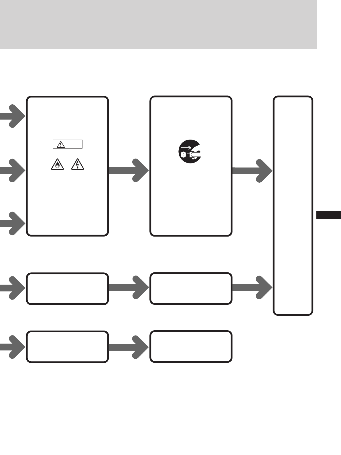
警告
ソニー製品は正しく使用すれば事故がおきないように、安全には
十分配慮して設計されています。しかし、まちがった使いかたを
すると、火災などにより死亡など人身事故になることがあり危険
です。事故を防ぐために次のことを必ずお守りください。
安全のために
v
安全のための注意事項を守る
この冊子の注意事項をよくお読みください。
定期的に点検する
警告表示の意味
取扱説明書および製品で
は、次のような表示をし
ています。表示の内容を
よく理解してから本文を
お読みください。
警告
この表示の注意事項を守
らないと、火災・感電な
どにより死亡や大けがな
ど人身事故の原因となり
ます。
お買い上げ時とその後1年に1度は「安全点検リスト」(8ページ)に
従って点検してください。
故障したら使わない
すぐにお買い上げ店またはソニーのサービス窓口に修理をご依頼
ください。
万一、異常が起きたら
・煙が出たら
・変なにおいや音がしたら
・内部に水などが入ったら
・内部に異物が入ったら
・ モニターを落としたり、
キャビネットを破損したと
きは
1電源を切る
b
2電源プラグをコンセント
から抜く
3お買い上げ店またはソ
ニーのサービス窓口に修
理を依頼する
注意
この表示の注意事項を守
らないと、感電やその他
の事故によりけがをした
り周辺の家財に損害を与
えたりすることがありま
す。
注意を促す記号
火災
行為を禁止する記号
禁止
水場での
使用禁止
感電
分解禁止
接触禁止
4
行為を指示する記号
プラグをコン
セントから抜く
Page 5
下記の注意を守らないと
警告
火災
感電
火災・感電により死亡や
大けがの原因となります。
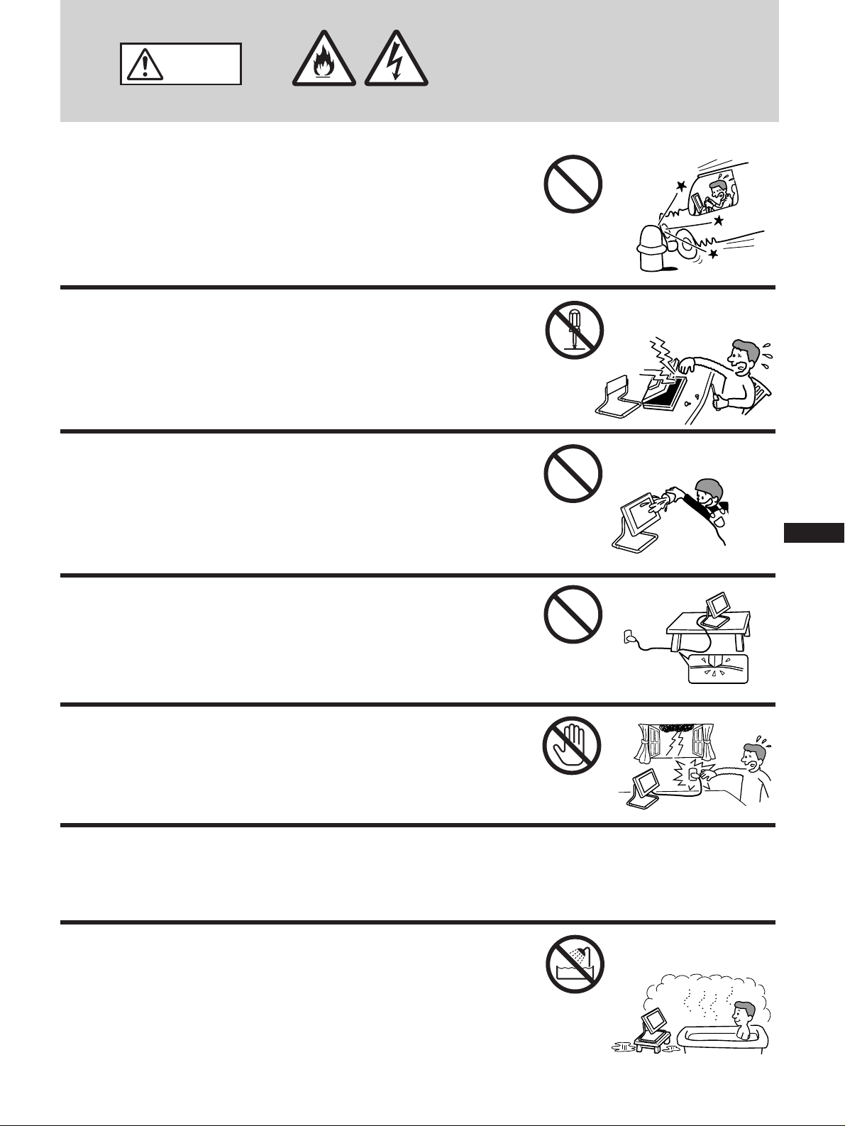
自動車の中では使わない
本機は車載仕様ではありません。
分解や改造をしない
内部には電圧の高い部分があり、裏ぶたを開けたり改造したりす
ると、火災や感電、故障の原因となります。
内部の点検や修理はお買い上げ店またはソニーサービス窓口にご
依頼ください。
内部に水や異物を入れない
禁止
分解禁止
水や異物が入ると火災の原因となります。万一、水や異物が入っ
た場合は、すぐに本体の電源スイッチを切り、電源プラグをコン
セントから抜いて、お買い上げ店またはソニーサービス窓口にご
依頼ください。
電源コードを傷つけない
電源コードを傷つけると、火災や感電の原因となります。
万一電源コードが傷んだ場合は、お買い上げ店またはソニーサー
ビス窓口に交換をご依頼ください。
雷が鳴りだしたら、電源プラグに触れない
感電の原因となります。
付属の電源コードを使用する
それ以外の電源コードを使用すると、火災や感電の原因となりま
す。
禁止
J
EN
F
D
禁止
ES
I
接触禁止
水のある場所に置かない
水が入ったり、濡れたり、風呂場で使うと、火災や感電の原因と
なります。雨天や降雪中の窓際でのご使用には特にご注意くださ
い。
水場での
使用禁止
5
Page 6
下記の注意を守らないとけがをしたり周辺の家財
注意
に損害を与えたりすることがあります。
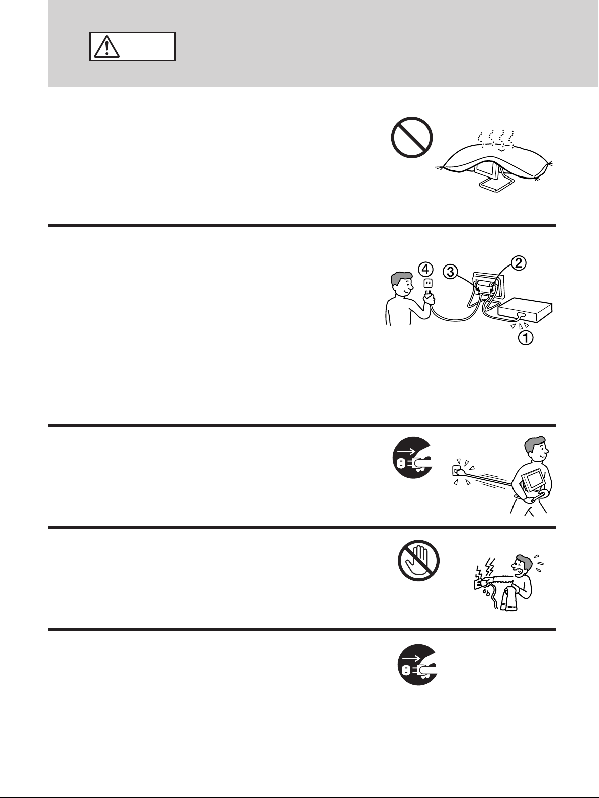
通風孔をふさがない
通風孔をふさぐと内部に熱がこもり、ケースが変形したり、火災
の原因となることがあります。通風を確保するために、製品の周
囲にはものを置かないでください。
・ あお向けにしない。
・ 布や布団を上に置かない。
電源プラグをつなぐのは、コンピューター機器ある
いはビデオ機器との接続が終わってから
電源プラグをコンセントに差し込んだまま接続すると、感電の原
因となることがあります。
接続が終わったあと、モニターの電源コードをモニター本体につ
ないでから、壁のコンセントに差してください。
禁止
電源コードを抜くときは壁側コンセントから抜く
壁側コンセントからではなく、モニター側から先に抜くと感電す
ることがあります。抜くときは右図の
ときは必ずコードでなくプラグをもって抜いてください。
4321
の順です。抜く
移動させるときは、電源プラグを抜く
電源プラグを差し込んだまま移動させると、電源コードが傷つ
き、火災や感電の原因となることがあります。
運ぶときは、衝撃を与えないように注意してください。
濡れた手で電源プラグにさわらない
濡れた手で電源プラグの抜き差しをすると、感電の原因となるこ
とがあります。
旅行などで長期間、ご使用にならないときは、電源
プラグをコン
セントから抜く
接触禁止
プラグを抜く
安全のため、必ず電源プラグをコンセントから抜いてください。
6
プラグをコン
セントから抜く
Page 7
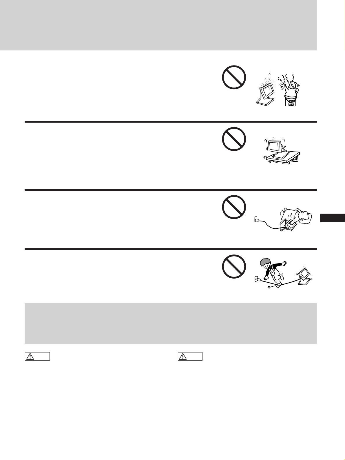
湿気やほこり、油煙、湯気の多い場所や、虫の入り
やすい場所、直射日光が当たる場所、熱器具の近く
に置かない
火災や感電の原因となることがあります。
安定した場所に設置する
ぐらついた台の上や傾いた所等に置くと、製品が落ちてけがの原
因となることがあります。
壁に取り付ける場合には、「設置する」(16ページ)をご参照の
上、十分に強度があり、落下しないところに取り付けてくださ
い。
通電中の製品に長時間ふれない
温度が相当上がることがあります。
長時間皮膚が触れたままになっていると、低温やけどの原因にな
ることがあります。
コード類は正しく配置する
電源コードやAVコードは足に引っかけると製品の落下や転倒な
どにより怪我の原因となることがあるため、十分注意して接続・
配置してください。
禁止
禁止
J
禁止
EN
F
D
ES
禁止
I
電池についての安全上のご注意
漏液、発熱、発火、破裂、誤飲などを避けるため、下記の注意事項を必ずお守りください。
警告
火の中に入れない。ショートさせたり、分解、加熱しな
•
い。
乾電池は充電しない。
•
指定された種類の電池を使用する。
•
注意
+と−の向きを正しく入れる。
•
電池を使い切ったとき、長時間使用しないときは、取り
•
出しておく。
新しい乾電池と使用した乾電池、種類の違う乾電池を混
•
ぜて使わない。
もし電池の液が漏れたときは、電池入れの液をよくふき
とってから、新しい電池を入れてください。万一、液が身
体や衣服についたときは、水でよく洗い流してください。
7
Page 8
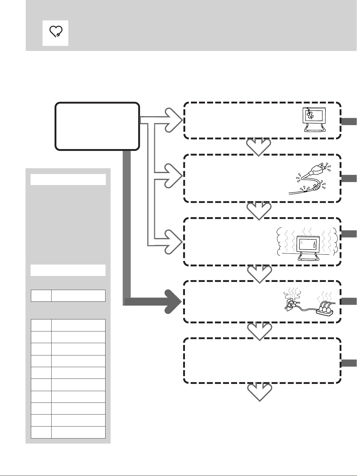
愛情点検
安全点検リスト
□印のチェック項目の中に1つでも
「はい」があると危険です。
そのときはすぐに対処してください。
スタート
設置したらすぐにチェックを!
そのあとの点検は
設置したすぐあとの
回目のチェックですか?
1
チェックのしかた
” 点検日を下記の欄にご記入
ください。
” 右図の矢印をたどりながら
各項目の□にチェックして
いきます。
” 故障内容(あれば)を下記に
ご記入ください。
点検日/故障内容
1年に1
度。
は
い
いいえ
□故障のまま使っている
□電源を入れても画像が出ないこと
がある
□画像が途切れたり、乱れたりする
いいえ
□電源コードを動かすと、電源が
入ったり切れたりする
□電源コードが折れ曲がっている、
キズついている
□電源コードやプラグが異常に熱い
いいえ
□本体が異常に熱い
□異常な熱や煙が発生したり、変
な臭いや音(パチパチ)がする
□通気孔から水や異物が入った形
跡がある
いいえ
回目、お買い上げ時
1
年月
/
回目以降,1年ごと
2
年月
/
年月
/
年月
/
年月
/
年月
/
年月
/
年月
/
年月
/
年月
/
年月
/
□たこ足配線している
□電源コードが他のものの下敷き
になっている
いいえ
□布やテーブルクロスで通風孔をふさいでいる
□油煙、湯気、湿気、ほこりの多いところに置い
ている
□不安定な置きかたをしている
いいえ
OK!
これからも安全に
お使いください。
8
Page 9
はい
1すぐに電源プラグを抜い
て使用を中止してくださ
い。
警告
はい
はい
はい
火災
そのままお使いになります
と火災・感電の原因となる
ことがあります。
そのままお使いになります
と事故の原因となることが
あります。
感電
プラグをコン
セントから抜く
2お買い上げ店、またはソ
ニーのサービス窓口にご
相談ください。
電源コードは専用のコンセ
ントにつなぎ、上には何も
のせないでください。
残りの項目も
チェックして
ください。
J
EN
F
D
ES
I
はい
そのままお使いになります
と事故の原因となることが
あります。
油気、湿気の少ない、換気
のよい場所に置いてくださ
い。
9
Page 10
使用上のご注意
置いてはいけない場所
使用中、保管中にかかわらず、次のような場所に置かない
でください。故障の原因になります。
異常に高温になる場所
•
炎天下や夏場の窓を閉め切った自動車内はとくに高温に
なり、放置すると変形したり、故障したりすることがあ
ります。
直射日光の当たる場所、熱器具の近く
•
変形したり、故障したりすることがあります。
激しい振動のある場所
•
強力な磁気のある場所
•
砂地、砂浜などの砂ぼこりの多い場所
•
海辺や砂地、あるいは砂ぼこりが起こる場所などでは、
砂がかからないようにしてください。故障の原因になる
ばかりか、修理できなくなることがあります。
液晶画面を太陽にむけたままにしない
•
液晶画面を傷めてしまいます。窓際や室外に置くときな
どはご注意ください。
電源接続について
付属の電源コードをお使いください。
安全のため電源コードにはアース線が
付けられています。コンセントにプラ
グを差し込む前に必ずアース線をアー
スへ接続してください。
プラグ形状例
AC100V
用
液晶画面について
液晶画面を強く押したり、ひっかいたり、上にものを置
•
いたりしないでください。画面にムラが出たり、液晶パ
ネルの故障の原因になります。
寒い所でご使用になると、画像が尾を引いて見えること
•
がありますが、故障ではありません。温度が上がると元
に戻ります。
静止画を継続的に表示した場合、残像を生じることがあ
•
りますが、時間の経過とともに元に戻ります。
画面上に常時点灯している輝点(赤、青、緑など)がある
•
場合がありますが、故障ではありません。
液晶パネルは非常に精密な技術で作られており、
99.99%
けや常時点灯する画素があります。
使用中に画面やケースが熱くなりますが、故障ではあり
•
ません。
以上の有効画素がありますが、
0.01%
の画素欠
蛍光管について
本機は内部照明装置として専用蛍光管を使用しております
が、この蛍光管には寿命があります。画面が暗くなった
り、チラついたり、点灯しないときは、新しい専用蛍光管
に取り替えてください。蛍光管の交換については、お買い
上げ店またはソニーサービス窓口にお問い合わせくださ
い。
パワーセーブ機能について
信号入力がなくなると「
にバックライトが消えます。信号が再入力されると、自動
的にバックライトが点灯します。
NO. SYNC
」と表示され、約5秒後
ファンモーターの回転異常保護装置に
ついて
本機に搭載されているファンモーターには、異常停止する
と自動的に電源を切る保護装置が付いています。異常停止
すると、「
ます。この場合は、すぐに電源プラグを抜いて、お買い上
げ店またはソニーサービス窓口に点検や修理をご依頼くだ
さい。
WARNING
」表示が出て、約60秒後に電源が切れ
お手入れについて
お手入れをする前に、必ず電源プラグをコンセントから
•
抜いてください。
液晶の画面は特殊加工がされていますので、なるべく画
•
面にふれないようにしてください。また画面の汚れを拭
き取るときは、柔らかく乾いた布で拭き取ってくださ
い。
アルコール、シンナー、ベンジンなどは使わないでくだ
•
さい。変質したり、塗装がはげたりすることがありま
す。
化学ぞうきんをご使用の際は、その注意書きに従ってく
•
ださい。
殺虫剤のような揮発性のものをかけたり、ゴムやビニー
•
ル製品に長時間接触させると、変質したり、塗装がはげ
たりすることがあります。
使用について
強力な電波を出すところや放射線のある場所で使わない
•
でください。
ラジオチューナーなどの受信機器の近くなどで使うと、
•
機器側に雑音が入ることがあります。
本機は、低温において電源投入時に、ビデオ信号のアン
•
ダースキャンモードにて、ジッターや二重映りがしばら
くの間、まれに起こる場合があります。そのときは、数
分間信号を入力したまま通電してからご使用ください。
リモコン取り扱い上のご注意
落としたり、踏みつけたり、中に液体をこぼしたりしな
•
いよう、ていねいに扱ってください。
直射日光が当たるところ、暖房器具のそばや湿度が高い
•
ところには置かないでください。
10
Page 11
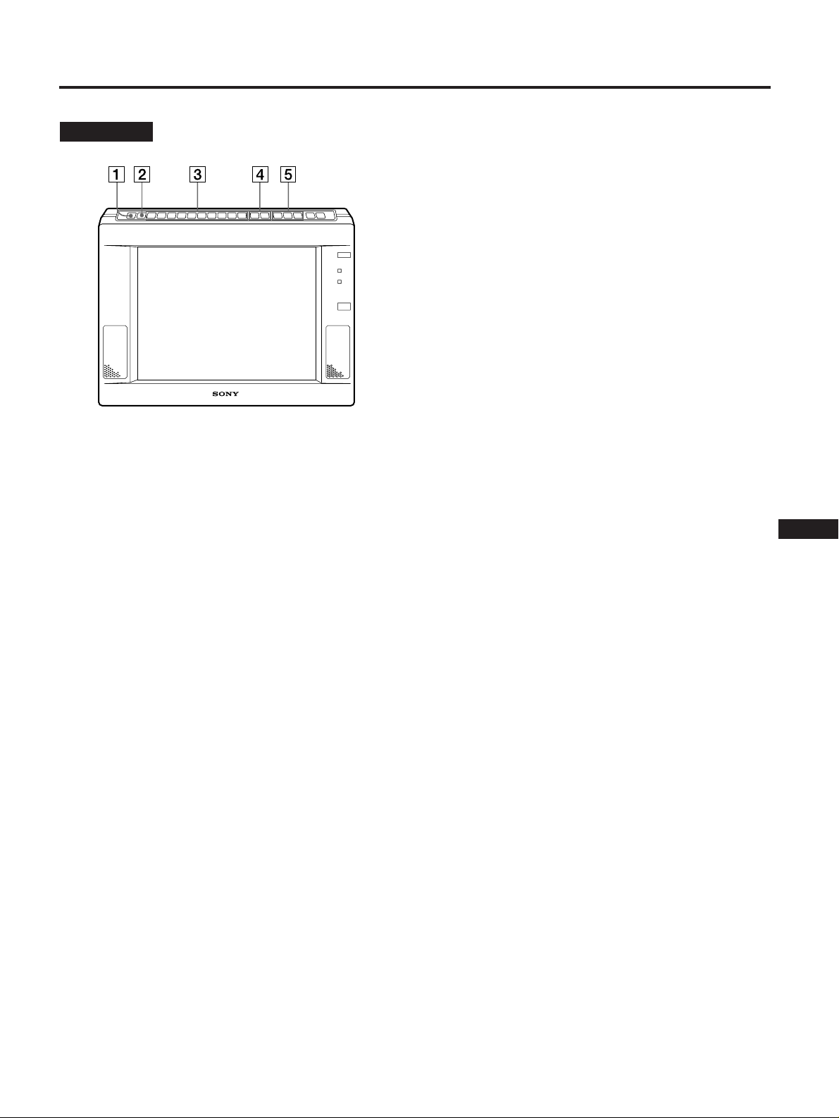
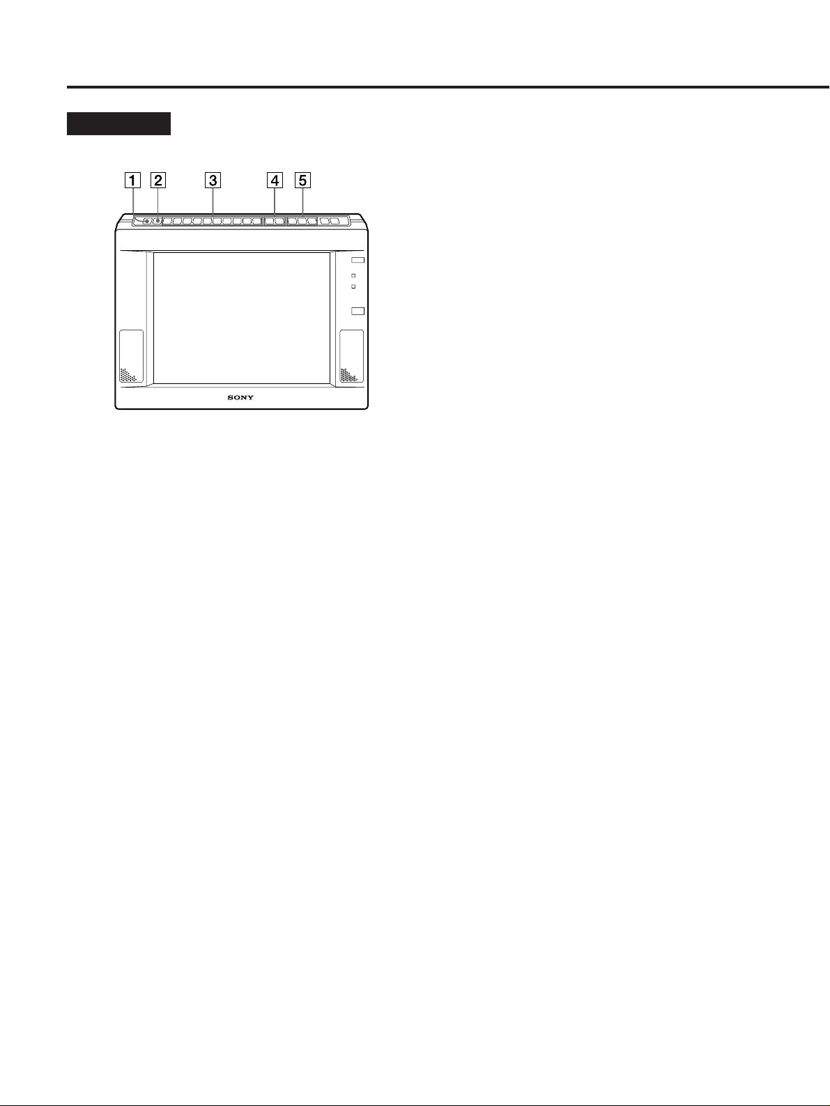
各部の名称と働き
前面・上面
1
INDEX
本機のインデックス番号を表示するときに押します(
ページ)。
本機には
本機を
号を使い、特定のセットを選んでリモコン操作するこ
とができます。
2
U SCAN
ビデオ画面の大きさと表示範囲を切り換えるときに押
します。
ボタン
台ごとにインデックス番号を設定できます。
1
台以上使用しているとき、このインデックス番
2
(アンダースキャン)ボタン
3 調整項目ボタン
調整したい項目のボタンを押した後、+/ーボタン4
で調整します。
入力信号により、調整できる項目が異なります。次
ページの表をご覧ください。
V POS
コンピューター信号の画像の、垂直方向の位置を調整
します。
H PH
コンピューター信号およびビデオ信号の画像の、水平
方向の位相ずれによるジッターや文字ぼけ、色のにじ
みを調整します。
H SIZE
コンピューター信号およびアンダースキャンモード時
のビデオ信号の画像の、水平方向の大きさを調整しま
す。
ボタン
ボタン
ボタン
18
H POS
コンピューター信号およびアンダースキャンモード時
のビデオ信号の画像の、水平方向の位置を調整しま
す。
SHARP
LINE AとLINE B
画像の輪郭を調整します。
COLOR
LINE AとLINE B
色の濃さを調整します。
HUE
LINE AとLINE B
色合いを調整します。
ます。
PIC
各信号の画像のコントラストを調整します。
LIGHT
画面の輝度(バックライト)を調整します。(
角は変わりません。)
BRT
画面の輝度を調整します。(
す。)
ボタン
ボタン
ボタン
ボタン
ボタン
ボタン
ボタン
、または
、または
、または
NTSC
LINE C (YUV)
LINE C (YUV)
LINE C (YUV)
方式の信号のみ調整でき
の信号の、
の信号の、
の信号の、
LCD
の視野角を調整しま
LCD
の視野
4 +/ーボタン
調整ボタン3で選んだ項目を調整します。
5 信号入力ボタン
映したい信号を選びます。
LINE A
LINE A
ます。
LINE B
LINE B
ます。
LINE C
LINE C
ます。押すたびに
モードが切り換わります。
た信号によってモード(コンピューター信号か
RGB
コンピューター信号についてのご注意
水平方向の大きさによっては、文字などに色の付いた影が
出ることがあります。
付かない大きさにしてください。
ボタン
端子!ªに入力されている映像/音声信号を選び
ボタン
端子!•に入力されている映像/音声信号を選び
ボタン
端子!¶に入力されている映像/音声信号を選び
RGB
信号と
YUV(Y/B-Y/R-Y)
モードでは、入力され
RGB
信号の
VIDEO
信号か)が自動的に切り換わります。
H PH、H SIZE、H POS
調整で色が
J
EN
F
D
ES
I
11
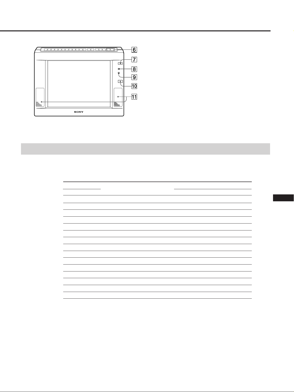
Page 12
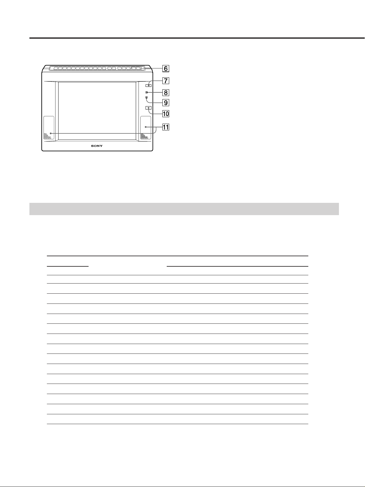
各部の名称と働き
6
VOLUME
音量を調節します。
7
POWER
電源を入/切します。
8
POWER
POWER
(緑)。
9
STANDBY
POWER
(赤)。
!º リモコン受光部
!¡ スピーカー
入力信号と調整できる項目
各入力信号で機能する調整項目ボタンは、下表のとおりです。
〇 調整できます。( )内は、アンダースキャンモード時のみ調整できます。
× 調整できません。
+/ーボタン
スイッチ
ランプ
スイッチ7が「入」になっていると点灯します
ランプ
スイッチ7が「切」になっていると点灯します
入力信号
調整項目ボタン
INDEX
U SCAN
V POS
H PH
H SIZE
H POS
SHARP
COLOR
HUE
PIC
LIGHT
BRT
RESET
VOLUME +/–
MUTING
*
のみ調整できます。
NTSC
LINE A LINE B LINE C
COMPUTER VIDEO RGB YUV
〇〇 〇 〇 〇
〇〇 × 〇 〇
×× 〇 × ×
〇〇 〇 〇 〇
×(〇) ×(〇) 〇 ×(〇) ×(〇)
×(〇) ×(〇) 〇 ×(〇) ×(〇)
〇〇 × × 〇
〇〇 × × 〇
〇* 〇* × × 〇*
〇〇 〇 〇 〇
〇〇 〇 〇 〇
〇〇 〇 〇 〇
〇〇 〇 〇 〇
〇〇 〇 〇 〇
〇〇 〇 〇 〇
12
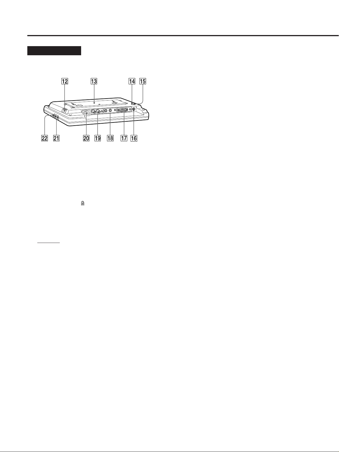
Page 13
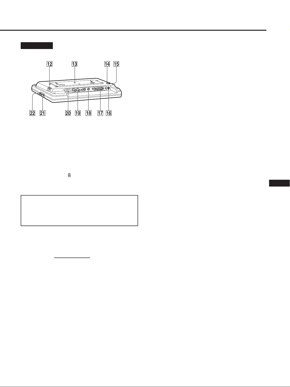
後面・下面
!¶
(
(ラインC信号入力)端子
LINE C
アナログ
Y/R-Y
端子(3列Dサブ15ピン)
IN
映像機器やコンピューターの
Y/B-Y/R-Y
(コンピューター/
RGB
)信号入力です。
)信号出力端子と接続します。
VIDEO)/YUV(Y/B-
出力端子または
RGB
YUV
!™
MAIN POWER
本機の主電源を入れるときに押します
(主電源)スイッチ
!£ 取り付け板
壁にかけたり、付属のスタンドを取り付けて卓上に置
いて使ったりすることができます。
!¢ 盗難防止用ロック( )
市販の盗難防止用ケーブル(
続することができます。
盗難防止用ロックは、
バーセキュリティシステム
内総販売代理店の連絡先は、日本ポラロイド株式会社
電子映像事業部です。
*マイクロセーバーセキュリティシステムは
社の登録商標です。
!∞
「
!§
(リセット)ボタン
RESET
度押すと、下記の項目を除く、調整を工場出荷時の設
2
定に戻します。
リセットされない項目
INDEX」「U SCAN」「LIGHT」「MUTE」「DISP
CONTROL
他の機器のコントロール端子を接続すると、接続した
機器で本機を調整できます。信号プロトコルは
プロトコルです。
(コントロール)端子(4ピン)
Kensington
Kensington
社製のマイクロセー
*
に対応しています。日本国
社製)などを接
Kensington
」
VISCA
AUDIO IN
映像機器やコンピューターの音声ライン出力と接続し
ます。
!•
LINE B
NTSC/PAL
Y/C IN
映像機器の
Y/C OUT
Y/C IN
ルー出力されます。なにもつながれていないと、
信号を自動的に75
IN
AUDIO IN
映像機器の音声出力と接続します。
!ª
LINE A
NTSC/PAL
す。
VIDEO IN
映像機器のコンポジットビデオ信号出力端子と接続し
ます。
VIDEO OUT
VIDEO IN
ルー出力されます。なにもつながれていないと、
VIDEO IN
AUDIO IN
映像機器の音声出力と接続します。
@º
AC IN
付属の電源コードをつなぎます。
@¡
CONTROL S IN/OUT
子
ソニーの機器の
のリモコンでシステム全体をコントロールすることが
できます。
(音声入力)端子(ピン)
(ラインB信号入出力)端子
方式の
(入力)端子(4ピン)
ビデオ信号出力端子と接続します。
Y/C
(出力)端子(4ピン)
端子に入力された映像信号がそのままループス
(音声入力)端子(ピン)
(ラインA信号入出力)端子
方式のコンポジットビデオ信号の入出力で
(ビデオ入力)端子(
(ビデオ出力)端子(
端子に入力された信号がそのままループス
信号を自動的に75
(音声入力)端子(ピン)
(電源入力)コネクター
信号の入出力です。
Y/C
に終端します。
Ω
(コントロールS信号入出力)端
CONTROL S
型)
BNC
型)
BNC
に終端します。
Ω
端子と接続すると、1台
Y/C
J
EN
F
D
ES
I
@™
PHONES
ヘッドホン(別売り)をつなぎます。
(ヘッドホン)端子
13
Page 14
ill025
各部の名称と働き
リモコン
1
MUTING
音を消すときに押します。もう一度押すと、音が出ま
す(17ページ)。
2
DISPLAY
画面表示を出すときに押します。もう一度押すと、消
えます。
3
U SCAN
画面の大きさと表示範囲を切り換えるときに押しま
す。
4POWER
電源を入/切します。
ボタン
ボタン
ボタン
スイッチ
7 +/ーボタン
調整項目ボタン!¡で選んだ項目を調整します。
8
+/ーボタン
VOL
音量を調節します。
9 電池入れ
型乾電池を2本入れます。
単
3
!º
RESET
2
定に戻します。
リセットされない項目
「
ボタン
度押すと、下記の項目を除く、調整を工場出荷時の設
INDEX」「U SCAN」「LIGHT」「MUTE」「DISP
!¡ 調整項目ボタン
調整したい項目のボタンを押して、+/ーボタン7で
調整します。
各ボタンは、本体と同じ働きをします(
!™
!£
ボタン
ID ON
インデックスモードにするときに押します(
ジ)。
ボタン
SET
インデックス番号を設定するときに使います(
ジ)。
本機には1台ごとにインデックス番号を設定できます。
本機を
号を使い、特定のセットを選んでリモコン操作するこ
とができます。
台以上使用しているとき、このインデックス番
2
ページ)。
11
18
電池の入れかた
」
ペー
18
ペー
5 信号入力ボタン
映したいライン信号を選びます。
LINE A
LINE A
ます。
LINE B
LINE B
ます。
LINE C
LINE C
信号または映像/音声信号を選びます。押すたびに、
どちらかの信号に切り換わります。
6
ID OFF
インデックスモードを出て、通常モードに戻るときに
押します(18ページ)。
14
ボタン
端子!ªに入力されている映像/音声信号を選び
ボタン
端子!•に入力されている映像/音声信号を選び
ボタン
端子!¶に入力されているコンピューター/音声
ボタン
電池入れのふたを押しながらずらす。
1
単3型乾電池を2本入れる。
2
ふたを元に戻す。
3
乾電池について
乾電池の使いかたを誤ると、液もれや破裂のおそれがあり
ます。次のことは必ずお守りください。
と’の向きを正しく入れてください。
• ‘
新しい乾電池と使用した乾電池、または種類の違う乾電
•
池を混ぜて使用しないでください。
乾電池は充電できません。
•
長い間乾電池を使わないときは、取り出しておいてくだ
•
さい。
液もれがおこったときは、電池入れについた液をよく拭き
取ってから、新しい乾電池を入れてください。
Page 15
接続する
接続上のご注意
各機器の電源を切ってから接続を行ってください。
•
接続ケーブルはそれぞれの端子の形状に合ったものをお
•
使いください。
プラグはしっかり差し込んでください。接続が悪いとノ
•
イズの原因になります。
コードを抜くときは、必ずプラグを持って抜いてくださ
•
い。
各機器の取扱説明書もあわせてご覧ください。
•
外部コントロール入力端子および外部コントロール出力
•
端子の接続には、ソニー製の専用ケーブル(別売り)をお
使いください。
接続例
パソコン、
業務用カメラ、
など
VTR
ビデオカメラ、
ディスクプレーヤー、ゲーム機
など
• LINE C
(別売り)をお使いください。
コンピューター ケーブル
Macintosh
VGA
PC-98
1)
MacintoshはApple Computer Inc.
2)
VGAはIBM
3)
PC-98
信号 ケーブル
端子の接続には、下表のソニー製専用ケーブル
1)
2)
3)
は日本電気(株)の登録商標です。
SMF-401
アダプター
SMF-401
SMF-401
変換アダプター
の登録商標です。
YUV SMF-400
VIDEO-RGB SMF-400
業務用
VTR
VTR
、レーザー
プレーヤーなど
と市販の
と市販の
、レーザーディスク
Macintosh
PC-98
の登録商標です。
用変換
シリーズ用
J
EN
アナログ
出力、コンポー
ネント信号出力
(
RGB
)へ
YUV
他の機器のコン
トロール端子へ
他のモニターの
へ
Y/C IN
音声出力
端子へ
電源コンセントへ
他のモニターの
VIDEO IN
へ
電源コード
(付属)
S
端子へ
YC-5V
ブルなど
RK-G129
映像出力
ケー
ケーブルなど
RK-G67
他のモニターの
コントロール
出力へ
ケーブルなど
F
D
ES
S
I
他のモニターの
コントロール
入力へ
S
15
Page 16
設置する
付属のスタンドを取り付けて卓上に置いたり、壁に取り付
けたりすることができます。
スタンドを取り付ける
スタンドの取り付け部を、モニターの取り付け板
1
に差し込む。
付属のネジで、スタンドを仮留めする。
2
ill028
壁に取り付ける
ご注意
本機の重量(
•
取り付けてください。
取り付けネジは、市販の
•
取り付ける
落下防止ネジをはずして、取り付け板を取りはず
1
す。
取り付け板を壁の梁に市販のネジで固定する。
2
のネジ
4mm
)を支えることができる強度のある壁に
2kg
のものをお使いください。
4mm
落下防止ネジ
壁
高さを調節してから、ネジをしっかり締める。
3
モニターの裏面に、落下防止板(付属)をかける。
3
取り付け板にモニターをかける。
4
手順2と同じネジで、落下防止板を固定する。
5
16
Page 17
調整する
本機上面のボタン、またはリモコンを使って調整します。
画質を調整する
各信号ごとに独立して調整することができます。
調整したい信号の入力ボタンを押して、信号を入
1
力する。
LINE A LINE B LINE C
調整したい項目の調整項目ボタンを押す。
2
選ばれた項目と調整値を示すバー表示が画面に出ま
す。
例:
COLOR
を選んだ場合
音量を調節する
VOLUME
音が出ないようにする
リモコンの
もう一度押すと、音が出ます。
+/ーボタンで調節する。
VOLUME
MUTING
ボタンを押す。
MUTING
J
COL
画面を見ながら、+/ーボタンで調整する。
3
調整が終わったら
約5秒後に自動的にバー表示が消えます。
出荷時の設定に戻す
裏面の
RESET
直径
2.5mm
バックライトの輝度調整を除く、すべての調整値が工場出
荷時の状態に戻ります。
ボタンを2回押す。
程度のものを差し込んで押します。
RESET
EN
F
D
ES
I
17
Page 18
インデックスモードで使用する
本機を数台、
コンを使って調整をすると、接続している全部のモニター
が一緒に調整されます(通常モード)。
個別のモニターをリモコンで調整したいときは、モニター
のインデックス番号とリモコンのインデックス番号を合わ
せてから、調整します(インデックスモード)。
CONTROL S
端子で接続してあるとき、リモ
個別のモニターを操作する
調整したいモニターの
1
画面にモニターのインデックス番号が出ます。
リモコンの
2
画面にリモコンのインデックス番号が出ます。
モニターとリモコンのインデックス番号が同じで
3
あることを確認する。
4 SET
画面表示の色が、緑色から黄色に変わります。
調整する(18ページ)。
5
ID ON
ボタンを押す。
INDEX
ボタンを押す。
ボタンを押す。
インデックス番号を設定する
モニターのインデックス番号は、工場出荷時すべて「0」に設
定されています。
モニターのインデックス番号とリモコンのインデックス番
号を同じにしてから、調整します。
モニターの
1
画面にモニターのインデックス番号が出ます。
INDEX
モニターの+/ーボタンで変えたい番号にする。
2
リモコンの
3
INDEX
ID OFF
ボタンを押す。
INDEX ON
SET INDEX COMMANDER INDEX
No.0
モニターのインデックス番号
No.
ボタンを押す。
調整が終わったら、リモコンの
6
押す。
通常モードに戻ります。
手順4で、インデックス番号が 違う状態で
ンを押すと
画面表示の色が緑色から赤色に変わります。
PRESS ID ON KEY OR ID OFF KEY
ON COMMANDER
SET INDEX COMMANDER INDEX
No.0
調整をする場合は、
•
の番号をモニターと同じ番号に設定します。
調整を中断する場合は、
•
デックスモードから出ます。
No. 1
ボタンを押してからリモコン
ID ON
ID OFF
ID OFF
ボタンを押して、イン
ボタンを
ボタ
SET
18
Page 19
主な仕様
入力信号フォーマット
VIDEO
:
NTSC3.58、 PAL4.43
:動作周波数
RGB
fh 15kHz 〜 36kHz
fv 45Hz
AUDIO
VIDEO
信号レベル
音声入力:
ヘッドホン出力:16
スピーカー音声出力:
信号レベル
コンポジット:
Y/C
–5dBs 47k
: Y 1Vp-p
C(Burst)
NTSC 0.286Vp-p
PAL 0.3Vp-p
VIDEO RGB
信号レベル
R、G、B:0.7Vp-p
:
1.0Vp-p
YUV
C SYNC
信号レベル
R-Y、B-Y:0.7Vp-p
:
Y
1.0Vp-p(SYNC 0.3V
信号入力レベル
RGB
セパレートシンク:
コンポジットシンク:
シンクオングリーン:
外部コントロール
プロトコル
VISCA
パネル
LCD
パネルタイプ:
a-Si TFT
画面サイズ:
実表示:
NTSC:約10.1
PAL:約10.3
RGB:640 × 480
有効画素数:
画素数:
電源電圧
消費電力量
AC100〜240V、50〜60Hz
28W
スタンバイ時
最大外形寸法
約
(突起部含まず)
質量 約
付属品 リモコン(1)
リモコン用乾電池(
スタンド(
スタンド留めネジ(
落下防止板(
電源コード(
640RGB × 480
(最大)
305×215.3×57.4mm
2kg
)
1
〜
73Hz
以上
Ω
以上
Ω
0.5W+0.5W
1Vp-p
±2dB
(75
±2dB
にて)
(75
Ω
±2dB
含む)
レベル ネガ、ポジ
TTL
レベル ネガ
TTL
0.3Vp-p
アクティブマトリックス
インチ
10.4
インチ
インチ
ドット、
99.9%
ドット
(最大)
7W
(幅/高さ/奥行き)
)
2
)
2
)
1
)
1
Ω
±2dB
(75
ネガ
にて)
(75
にて)
Ω
10.4
にて)
Ω
インチ
LINE C
モード
ピン番号
入力端子ピン配置
5
10
15 11
1
6
COMPUTER VIDEO RGB YUV
1 R R R-Y
2G G Y
3 B B B-Y
4 GND GND GND
5NCNCNC
6 GND GND GND
7 GND GND GND
8 GND GND GND
9 GND GND GND
10 NC NC NC
11 GND GND GND
12 NC NC NC
13 H/HV C SYNC
14 V
15
外部接続不可 外部接続不可 外部接続不可
外部接続不可 外部接続不可
外部接続不可
J
EN
F
D
ES
I
本機の仕様および外観は、改良のため予告なく変更するこ
とがありますが、ご了承ください。
19
Page 20

故障かな?と思ったら
修理にお出しになる前に、もう一度点検してください。そ
れでも正常に動作しないときは、お買い上げ店またはソ
ニーサービス窓口にお問い合わせください。
こんなときは 次のことを確認してください 参照ページ
画像が出ない
POWER
•
•
ランプも
電源コードがきちんとつながれていますか?
電源スイッチは入っていますか?
STANDBY
ランプも点灯しない場合
15
12
「
NO SYNC
ジが出た
画像が乱れている
コンピューターの画像が画面
の中央からずれている、画像
の大きさが合っていない
」というメッセー
POWER
•
•
•
•
•
•
マッキントッシュ用変換アダプターを使用している場合
•
ビデオ同期信号が本機の仕様に対応していますか?
画像調整を行ってください。
「
H POS
ランプが点灯している場合
接続機器の電源は入っていますか?
映したい信号が正しく選択されていますか?
コンピューターモードで使用している場合は、コンピューターのキー
ボードのキーのどれかを押してみてください。
信号ケーブルは正しく接続されていますか?(マッキントッシュや、
一部の
す。)
信号ケーブルのピンが曲がっていませんか?
同期信号は本機の仕様に適合していますか?(水平:15〜
直:
45〜73Hz
アダプターのスイッチは正しく設定されていますか?(アダプターの
説明書で確認してください。)
」、「
シリーズの場合は、市販の変換アダプターが必要で
PC-98
)
V POS
」、「
H SIZE
」ボタンで調整してください。
36kHz
11
15
、垂
12,17
12,17
コンピューターの画像がくっ
きりしていない
ビデオの画像がくっきりして
いない
LINE C
れる
ビデオ画像が縮小されている
画像は出るが音が出ない
色がつかない、色がおかし
い、画面が暗い
リモコンで操作できない
の画像が2画面に分か
20
「
「
」、「
H PH
SHARP
LINE C
U SCAN
音量が下がりきっていませんか?
•
ヘッドホンをつないでいませんか?
•
画面に「
•
H POS
」ボタンで調整してください。
ボタンをもう一度押してください。
ボタンを押してください。
MUTE
MUTING
画質を調整してください。
リモコンの電池が消耗していませんか?
」、「
H SIZE
」が表示されていませんか?
ボタンを押してください。
」ボタンで調整してください。
12,17
12,17
17
11
17
17
12,17
14
Page 21
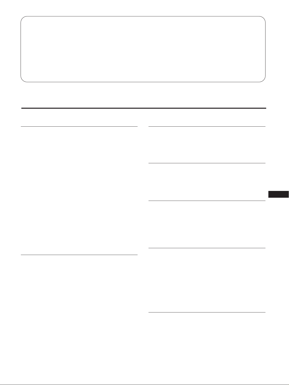
Table of Contents
Precautions ..................................................................................................................3
Functions of Controls.................................................................................................4
Connections ................................................................................................................. 8
Installation ................................................................................................................... 9
Adjustments .............................................................................................................. 10
Using the unit in index mode .................................................................................11
Specifications............................................................................................................. 12
Troubleshooting........................................................................................................ 13
Precautions
Using the unit
• Use the unit under stable temperatures between 0 °C and
40 °C (32 °F and 104 °F).
• Prevent internal heat build-up by allowing adequate air
circulation. Do not place the unit on surfaces (rugs,
blankets, etc.) or near materials (curtains, draperies) that
may block the ventilation holes.
• Do not install the unit near heat sources such as radiators
or air ducts, nor in a place subject to direct sunlight,
excessive dust, mechanical vibration or shock.
• Do not place the unit near equipment which generates
magnetism, such as a converter or high voltage power
lines.
• Do not use the unit near equipment which generates a
strong electric field or radiation.
• Do not use the unit near an AM/FM tuner. The unit may
cause noise on the tuner.
• When you turn on the unit and display the video signal in
under-scan mode in low temperature, you may find jitter
or double-image. This is not a malfunction of the unit.
Wait for a few minutes until jitter or double-image
automatically disappears.
Notes on handling the LCD screen
• Do not leave the LCD screen facing the sun as it can
damage the LCD screen. Take care when you place the
unit by a window.
• Do not push or scratch the LCD screen. Do not put a
heavy object on the LCD screen. This may cause
malfunction and the display may not appear uniform.
• If the unit is used in a cold place, a residual image may
appear on the screen. This is not a malfunction of the unit.
When the unit becomes warm, the screen returns to
normal.
• If a still picture is displayed for a long time, a residual
image may appear. The residual image will disappear in a
while.
• Bright points of light (red, blue or green) may appear
constantly on the LCD screen. This is not a malfunction.
The LCD screen is made with high-precision technology
and has more than 99.9 % of effective picture elements.
However, 0.01 % of picture elements may not appear or
some picture elements may appear constantly.
• The screen and the cabinet become warm during
operation. This is not a malfunction.
Replacement of the fluorescent tube
An exclusive fluorescent tube is installed as the lighting
apparatus of this unit. If the LCD screen becomes dark,
unstable or does not turn on, replace the fluorescent tube
with an new one. Consult your Sony dealer.
Power saving function
When there is no input signal, “NO. SYNC” appears on the
screen and the backlight turns off after about 5 seconds.
When a signal is input again, the backlight turns on
automatically.
If the fan motor stops suddenly
If the fan motor stops suddenly, the power of this unit is
turned off automatically to protect the fan motor.
If the fan motor stops suddenly, “WARNING” appears on
the LCD screen and the power is turned off after about 60
seconds. If this happens, disconnect the power cord and
consult your Sony dealer.
Maintenance
• Make sure to disconnect the power cord before cleaning
the unit.
• Avoid robbing the LCD screen as it can damage the LCD
screen. Use a dry and soft cloth to wipe the LCD screen.
• Clean the cabinet, panel and controls with a soft cloth
lightly moistened with a mild detergent solution. Do not
use any type of abrasive pad, scouring powder or solvent,
such as alcohol or benzine.
Notes on handling the remote
commander
• Handle the remote commander carefully. Do not drop or
step on the remote commander. Keep liquid away from
the remote commander.
• Do not place the remote commander under direct
sunlight, near heat sources or in a humid place.
J
EN
D
F
ES
I
3
Page 22
Functions of Controls
Front • Top
1 INDEX button
Shows the index number of the unit (page 11).
You can assign an index number to each unit. When
two or more units are installed at the same location, use
this index number to select a unit you want to control
using the remote commander.
COLOR button
Adjusts the color density for the LINE A, LINE B or
LINE C (YUV) signal.
HUE button
Adjusts the hue for the LINE A, LINE B or LINE C
(YUV) signal. Works with NTSC video signal only.
PIC button
Adjusts the picture contrast for all signals.
LIGHT button
Adjusts the brightness of the screen (backlight). (The
LCD angle against field of view does not change.)
BRT button
Adjusts the brightness of the screen. (The LCD angle
against field of view is adjusted.)
4 +/– buttons
Adjusts the selected parameter.
5 Signal input button
Selects the input signal.
LINE A button
Selects the video/audio signal input through the LINE
A connectors !ª.
2 U SCAN (under scan) button
Switches the size and viewable area of the image.
3 Adjusting parameter button
After selecting a parameter with these buttons, adjust
with the +/– buttons 4.
Adjusting parameters differs depending on the input
signal. See the table on the next page.
V POS button
Adjusts the picture position in the vertical direction for
the computer signal.
H PH button
Corrects the jitter, unclear characters and color bleeding
caused by the horizontal phase difference for the
computer signal and the video signal.
H SIZE button
Adjusts the picture size in the horizontal direction for
the computer signal and the video signal in under-scan
mode.
H POS button
Adjusts the picture position in the horizontal direction
for the computer signal and the video signal in underscan mode.
LINE B button
Selects the video/audio signal input through the LINE B
connectors !•.
LINE C button
Selects the video/audio signal input through the LINE
C connectors !¶. Each time you press the button, the
RGB signal mode and YUV (Y/B-Y/R-Y) signal mode
switches. In the RGB signal mode, the computer mode
or the VIDEO RGB mode switches automatically
depending on the input signal.
Note on the computer signal
The characters may have colored shade in some horizontal
sizes. Adjust the H PH, H SIZE or H POS parameter so that
the shade disappears.
SHARP button
Adjusts the picture sharpness for the LINE A, LINE B or
LINE C (YUV) signal.
4
Page 23
6 VOLUME +/– button
Adjusts the sound volume.
7 POWER switch
Turns power on or off.
8 POWER indicator
Lights in green when the POWER switch 7 is turned
on.
9 STANDBY indicator
Lights in red when the POWER switch 7 is turned off.
0 Remote sensor
!¡ Speaker
Input signal and adjustable parameters
The following table shows which parameters can be adjusted for each input signal.
Yes: You can adjust (Only possible in under-scan mode appears in parenthesis)
No: You cannot adjust
Input signal LINE A LINE B LINE C
Parameter button Computer Video RGB YUV
INDEX Yes Yes Yes Yes Yes
U SCAN Yes Yes No Yes Yes
V POS No No Yes No No
H PH Yes Yes Yes Yes Yes
H SIZE No (Yes) No (Yes) Yes No (Yes) No (Yes)
H POS No (Yes) No (Yes) Yes No (Yes) No (Yes)
SHARP Yes Yes No No Yes
COLOR Yes Yes No No Yes
HUE Yes * Yes * No No Yes *
PIC Yes Yes Yes Yes Yes
LIGHT Yes Yes Yes Yes Yes
BRT Yes Yes Yes Yes Yes
RESET Yes Yes Yes Yes Yes
VOLUME +/– Yes Yes Yes Yes Yes
MUTING Yes Yes Yes Yes Yes
* For NTSC only
J
EN
D
F
ES
I
5
Page 24
Functions of Controls
Rear • Bottom
!™ MAIN POWER switch
Turns on or off the main power of the unit.
!£ Hanging plate
You can hang the unit on the wall, or attach the stand
and place on a table.
!¢ Security lock ( )
You can attach the Kensington’s security cable (not
supplied).
!ª LINE A signal input/output connectors
Inputs/outputs the Composite signal of NTSC/PAL
system.
VIDEO IN connector (BNC)
Connect to the composite video signal output of video
equipment.
VIDEO OUT connector (4-pin)
Loop-though output of the VIDEO IN connector. When
no cable is connected, VIDEO IN signal is terminated at
75 Ω.
AUDIO IN connector (phono)
Connect to the audio output of video equipment.
@º AC IN connector
Plug in an AC power cord.
@¡ CONTROL S IN/OUT connector
Connect to the CONTROL S jacks of other Sony
equipment. It is then possible to control the whole
system with a single remote commander.
@™ PHONES jack
Connect headphones (not supplied).
!∞ RESET button
Recalls factory settings of the adjusting parameters
excluding INDEX, U SCAN, LIGHT, MUTE and DISP.
Press twice.
!§ CONTROL connector (4-pin)
Connect to the control jack of the equipment with which
you want to control this unit. The signal protocol is
VISCA.
!¶ LINE C signal input connectors
Inputs the analog RGB (computer/video)/YUV (Y/BY/R-Y) signal.
IN connector (3-row D-Sub 15-pin)
Connect to the RGB or YUV (Y/B-Y/R-Y) signal output
of video equipment or a computer.
AUDIO IN connector (phono)
Connect to the audio output of video equipment or a
computer.
!• LINE B signal input/output connectors
Inputs/outputs the Y/C signal of NTSC/PAL system.
Y/C IN connector (4-pin)
Connect to the Y/C video signal output of video
equipment.
Y/C OUT connector (4-pin)
Loop-though output of the Y/C IN connector. When no
cable is connected, Y/C IN signal is terminated at 75 Ω.
AUDIO IN connector (phono)
Connect to the audio output of video equipment.
6
Page 25

Remote Commander
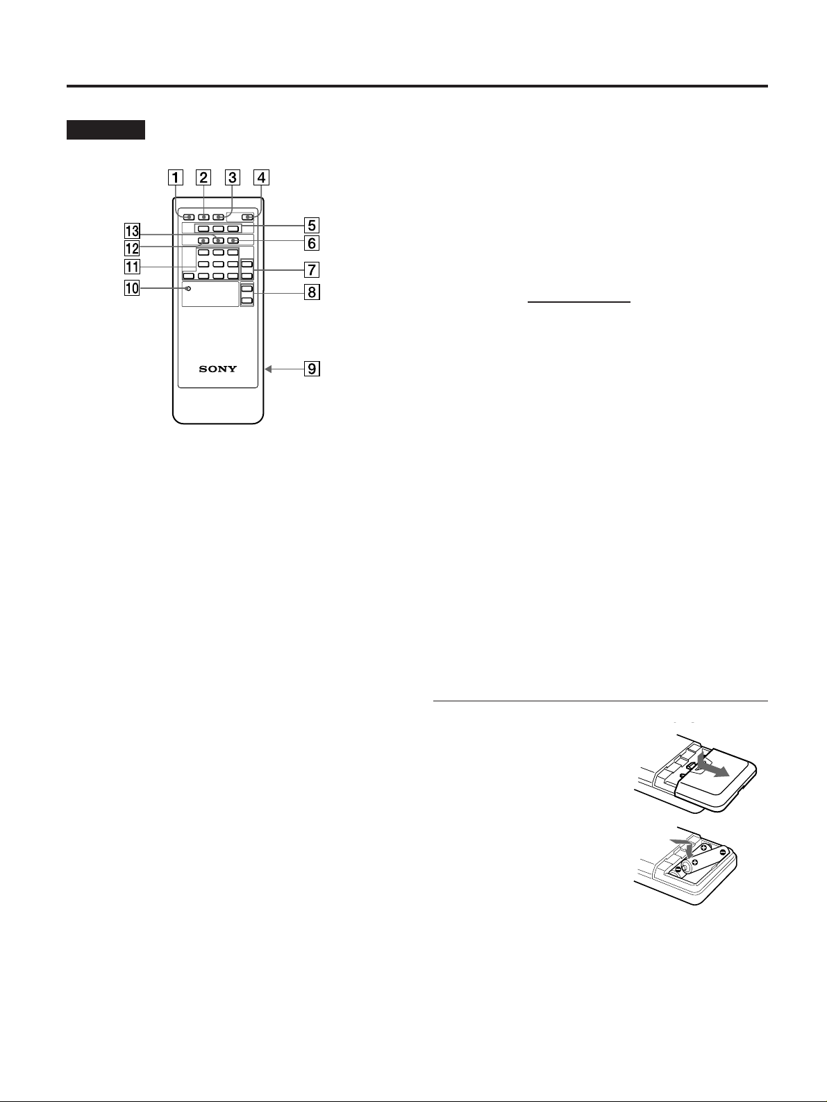
!º RESET button
Recalls factory settings of the adjusting parameters
excluding INDEX, U SCAN, LIGHT, MUTE and DISP.
Press twice.
!¡ Adjusting parameter button
After selecting an adjusting parameter with these
buttons, adjust with the +/- buttons 7.
The function of each button is identical with those on
the monitor.
!™ ID ON button
Switches from normal mode to index mode (page 11).
!£ SET button
Sets the index number (page 11).
You can assign an index number to each unit. When
two or more units are installed at the same location, use
this index number to select a unit you want to control
using the remote commander.
1 MUTING button
Mutes the sound. Press again to cancel muting (page 9).
2 DISPLAY button
Displays the indicator. Press again to turn off the
indicator.
3 U SCAN button
Switches the screen size and image area.
4 POWER switch
Turns power on or off.
5 Signal input button
Selects the input signal.
LINE A button
Selects the video/audio signal input through the LINE
A connectors !ª.
LINE B button
Selects the video/audio signal input through the LINE
B connectors !•.
LINE C button
Selects the computer/audio signal or the video/audio
signal input through the LINE C connectors !¶. Each
press of this button selects either signal alternately.
Inserting the batteries
1 Slide the lid to remove it.
2 Insert two size AA (R6) batteries by matching the ‘
and ’ on the batteries to the ‘ and ’ in the battery
compartment.
3 Slide the lid to replace it.
Battery life
You can expect the remote commander to operate for about
six months (using Sony SUM-3 (NS) batteries) before the
batteries run down. When the batteries no longer operate
the remote commander, replace all the batteries with new
ones.
J
EN
D
F
ES
I
6 ID OFF button
Switches from index mode to normal mode (page 11).
7 +/– buttons
Adjusts the selected parameter.
8 VOL +/– button
Adjusts the sound volume.
9 Battery compartment
Insert two size AA (R6) batteries.
To avoid battery leakage
If you are not going to use the remote commander for a long
time, remove the batteries to avoid damage caused by
corrosion from battery leakage.
7
Page 26

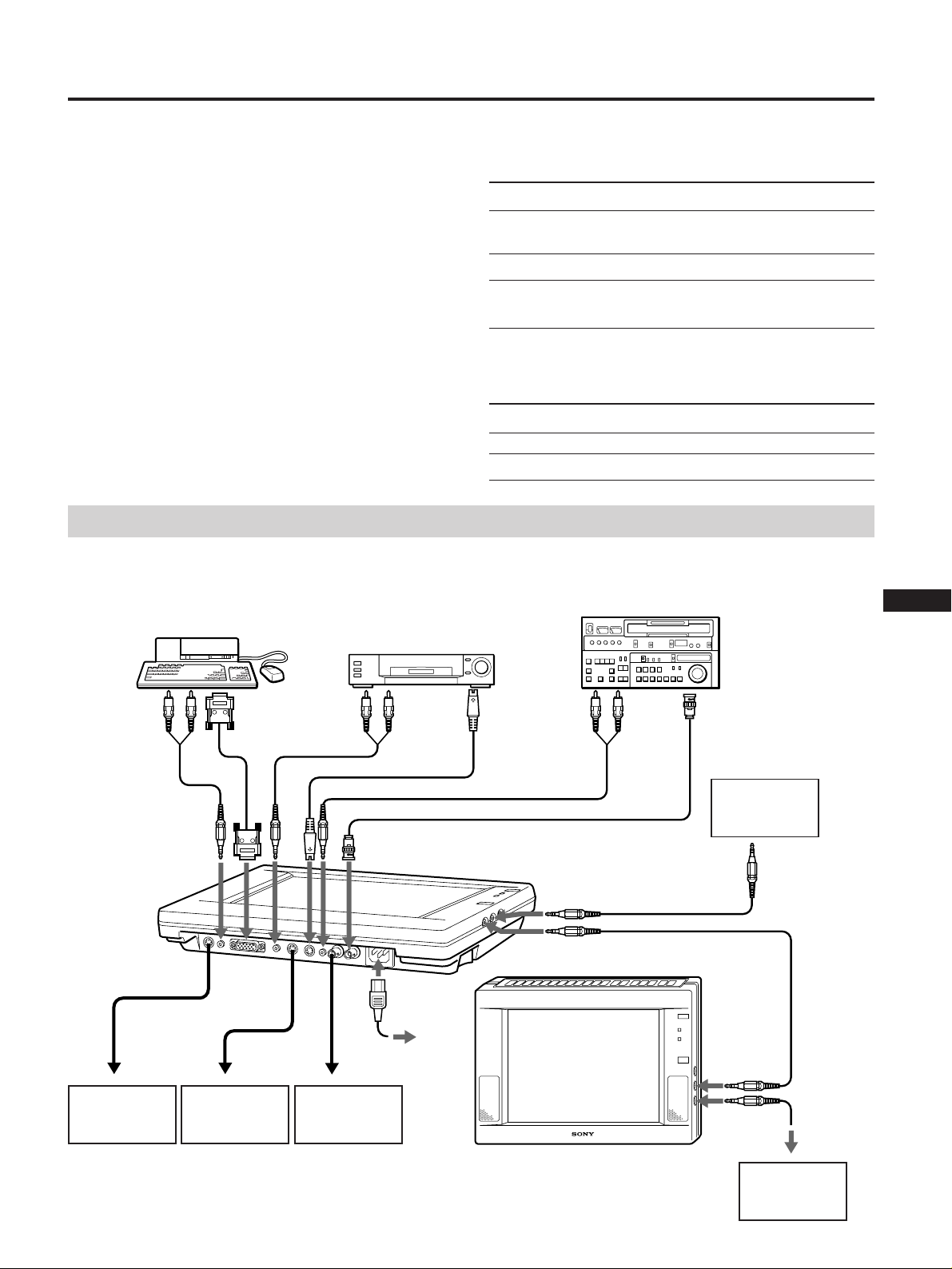
Connections
Before you get started
• First make sure that the power of each piece of equipment
is turned off.
• Use connecting cables suitable for the equipment to be
connected.
• Insert the cable connectors fully into the jacks. A loose
connection may cause hum and other noise.
• To disconnect the cable, pull out by grasping the plug.
• Use the following Sony cable (not supplied) to connect the
LINE C connector.
Computer Cable
Macintosh
VGA
PC-98
1)
2)
3)
Never pull the cable itself.
• Read the instruction manual of the equipment to be
connected.
• Use the Sony specific cable (not supplied) to connect the
external control jacks.
1) Macintosh is a registered trademark of Apple Computer
Inc.
2) VGA is a registered trademark of IBM.
3) PC-98 is a registered trademark of NEC Corporation.
Signal Cable
YUV SMF-400
Video-RGB SMF-400
Example of the equipment to be connected
Personal computer,
institutional video
camera/VTR, etc.
VTR, laser disc player,
video game, etc.
SMF-401 and Macintosh adaptor (not
supplied)
SMF-401
SMF-401 and PC-98 series adaptor (not
supplied)
Institutional VTR, laser
disc player, etc.
to analog RGB
output or
component signal
(YUV) output
to control
jack of other
equipment
to Y/C IN of
other
monitor
to audio
output
to VIDEO IN of
other monitor
Power cord
(supplied)
to a wall outlet
to S video
output
YC-5V cable,
etc.
RK-G129 cable, etc.
to control S
output of
other monitor
RK-G67 cable, etc.
8
to control S
input of other
monitor
Page 27

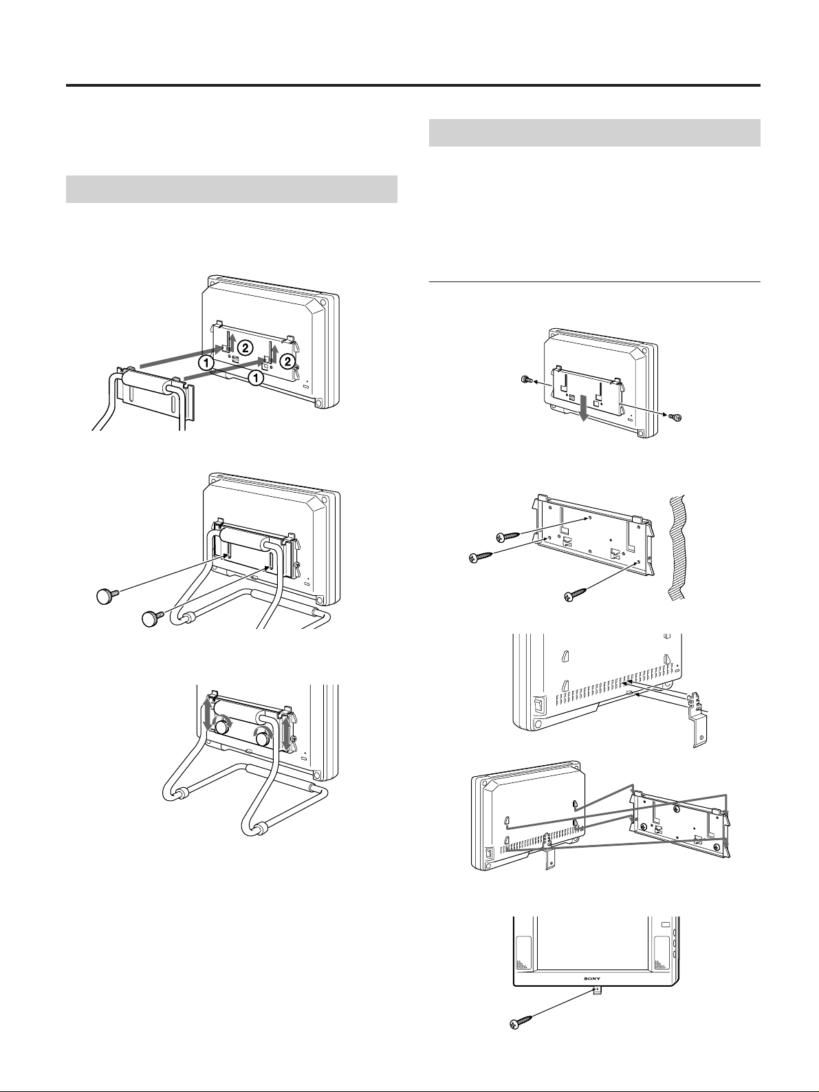
Installation
You can attach the stand to the unit and place on a table, or
hang the unit on the wall.
Attaching the stand
1 Align and insert the connecting plate of the
stand to the hanging plate of the monitor.
ill028
2 Loosely install the supplied screw.
Hanging on the wall
Caution
• Make sure that the wall is strong enough to hold 2 kg (4
lb 7 oz) weight.
• Use the 4 mm (3/16 inches) screw (not supplied).
Hanging on the wall
1 Remove the screws and remove the hanging plate
from the monitor.
Screw (to prevent the
monitor from falling)
2 Secure the hanging plate to the wall using the 4 mm
(3/16 inches) screws (not supplied).
Make sure that you attach the hanging plate to the cross
beam of the wall.
Wall
J
3 Adjust the height of the monitor, and tighten the
screws.
3 Hang the supplied plate to the rear of the monitor.
This plate is to prevent the monitor from falling.
4 Hang the monitor onto the hanging plate.
5 Secure the plate you hanged in step 3 with the same
screw as in step 2.
EN
D
F
ES
I
9
Page 28

Adjustments
You can make adjustments using the buttons on either the
monitor or the remote commander.
Adjusting the picture
You can make adjustments for each signal separately.
1 Press the signal input button of the signal you want
to adjust.
LINE A LINE B LINE C
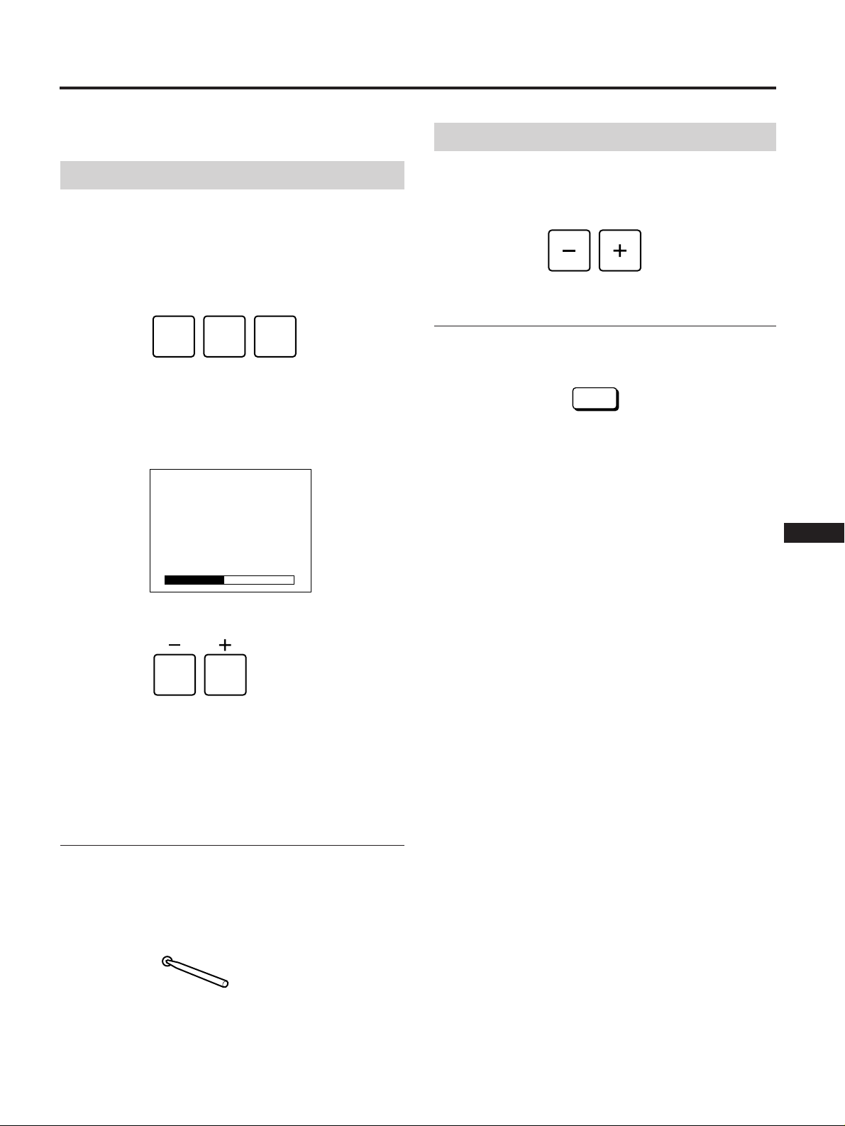
2 Select the parameter by pressing the adjustment
parameter buttons.
The selected parameter and its present setting in the bar
display appear.
Example: for the color adjustment
Adjusting the sound
Press the VOLUME + or – button.
VOLUME
Muting the sound
Press the MUTING button on the remote commander.
MUTING
Press again to cancel muting.
COL
3 Press the + or – button to adjust while watching the
picture.
When you finished the adjusting
The bar display automatically disappears after about 5
seconds.
Resetting the adjustment to the factory
setting
Press the RESET button using an object of 2.5 mm (1/8
inch) diameter.
All the parameters, except the backlight brightness, are reset
to the factory setting.
RESET
10
Page 29

Using the unit in index mode
When more than two monitors are connected via the
CONTROL S connector, you can adjust all the connected
monitors simultaneously using the remote commander
(Normal mode).
If you want to adjust a specific monitor using the remote
commander, set the remote commander to the same index
number as the monitor (Index mode).
Adjusting a specific monitor
1 Press the INDEX button on the monitor you want to
adjust.
The index number of the monitor appears.
2 Press the ID ON button on the remote commander.
The index number of the remote commander appears.
3 Confirm that the index numbers of the monitor and
the remote commander are the same.
4 Press the SET button.
The on-screen display changes from green to yellow.
5 Begin adjusting (page 10).
6 When you finish adjusting, press the remote
commander’s ID OFF button.
The monitor returns to normal mode.
If you press the SET button in step 4 when the
index numbers are different
The on-screen display changes from green to red.
Setting the index number
The monitor’s index number is set to “0” at the time of
delivery.
To adjust a specific monitor, first identify the index number
of the monitor and set the remote commander to the same
number, then begin adjusting.
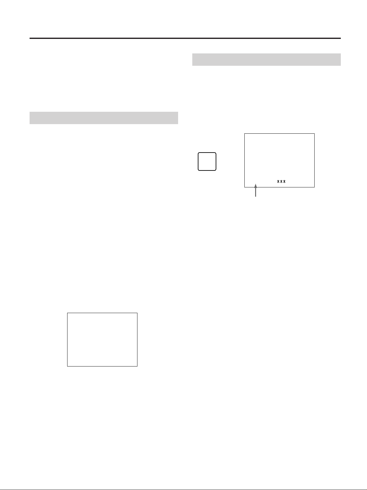
1 Press the INDEX button on the monitor.
The index number of the monitor appears.
INDEX ON
INDEX
SET INDEX COMMANDER INDEX
No.0
Monitor’s index number
2 Press the +/– buttons on the monitor to change the
index number.
3 Press the ID OFF button on the remote commander.
No.
J
EN
D
F
PRESS ID ON KEY OR ID OFF KEY
ON COMMANDER
SET INDEX COMMANDER INDEX
No.0
• To continue adjusting, press the ID ON button and set
the remote commander’s index number to the same as
that of the monitor.
• To cancel adjusting, press the ID OFF button and exit
from the index mode.
No. 1
ES
I
11
Page 30

Specifications
Input signal format VIDEO:
NTSC3.58, PAL4.43
RGB:
Operating frequency:
fh: 15 kHz — 36 kHz
fv: 45 Hz — 73 Hz
Audio signal level Audio input: –5 dBs, 47 kΩ or more
Headphones output: 16 Ω or more
Speaker output: 0.5 W + 0.5 W
Video signal level Composite:
1 Vp-p ± 2 dB (at 75 Ω)
Y/C: Y 1 Vp-p ± 2 dB (at 75 Ω)
C (Burst)
NTSC 0.286 Vp-p ± 2 dB (at
75 Ω)
PAL 0.3 Vp-p ± 2 dB (at 75 Ω)
Video RGB signal level
R, G, B: 0.7 Vp-p
C Sync: 1.0 Vp-p
YUV signal level R-Y, B-Y: 0.7 Vp-p
Y: 1.0 Vp-p (including Sync 0.3 V)
RGB signal input level
Separate Sync: TTL level, negative,
positive
Composite Sync: TTL level, negative
Sync-on-Green: 0.3 Vp-p, negative
External control VISCA protocol
LCD panel Panel type: a-Si TFT Active Matrix
Picture size: 10.4 inches
Image area:
NTSC Approx. 10.1 inches
PAL Approx. 10.3 inches
RGB 640 × 480 dots, 10.4 inches
Effective picture elements: 99.9 %
Picture elements: 640 RGB × 480 dots
Power requirements AC 100 – 240 V, 50 – 60 Hz
Power consumption Max. 28 W
Stand-by Max. 7 W
Dimensions Approx. 305 × 215.3 × 57.4 mm
(w/h/d)
1
/8 × 8 1/2 × 2 3/8 in.)
(12
not incl. projecting parts and controls
Mass Approx. 2 kg (4 lb 7 oz)
Supplied accessories
Remote commander (1)
R6 (size AA) batteries for remote
commander (2)
Stand (1)
Screws to secure the stand (2)
Plate (1)
Power cord (1)
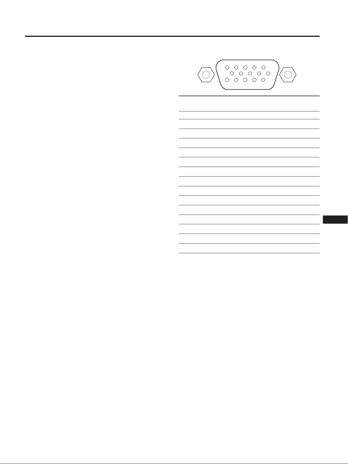
LINE C connector – pin assignment
5
10
15 11
Mode Computer VIDEO RGB YUV
Pin No.
1RRR-Y
2GGY
3BBB-Y
4 GND GND GND
5NCNCNC
6 GND GND GND
7 GND GND GND
8 GND GND GND
9 GND GND GND
10 NC NC NC
11 GND GND GND
12 NC NC NC
13 H/HV C SYNC External
14 V External connection is not
15 External connection is not possible.
1
6
connection is not
possible.
possible.
Design and specifications are subject to change without
notice.
12
Page 31

Troubleshooting
This section may help you isolate a problem and, as a result,
eliminate the need to contact technical support, allowing
continued productivity.
Symptom Check these items Page
No picture
“NO SYNC” message appears
Picture is scrambled
Computer picture is not
centered or sized properly
Computer picture is fuzzy
Video picture is fuzzy
LINE C picture is divided into
two
Video picture size is reduced
If neither POWER indicator nor STANDBY indicator is lit
• The power cord is properly connected.
• The power switch is in the ON position.
If the POWER indicator is lit
• The connected equipment is turned on.
• The desired signal is selected.
• If you are using the unit in computer mode, press any key on the
keyboard of the computer.
• The signal cable is correctly connected. (You need a commercially
available adaptor to connect Macintosh and some PC-98 series
computer.)
• No pins are bent or pushed in the connector of the cable.
• The video sync signal is within that specified for the monitor?
If you are using the Macintosh adaptor
• The dip switch is set correctly. (See the manual of the adaptor.)
The video sync signal is within that specified for the monitor.
Adjust the picture.
Adjust “H POS,” “V POS,” or “H SIZE.”
Adjust “H PH,” “H POS,” or “H SIZE.”
Adjust “SHARP.”
Press the LINE C button again.
Press the U SCAN button.
8
5
4
8
5, 10
5, 10
5, 10
5, 10
4
4
J
EN
D
F
ES
No sound
No color, unnatural color, or
dark
Remote commander does
not operate
• The volume is not turned down completely.
• The headphones are not connected.
• If “MUTE” is indicated on the screen, press the MUTING button.
Adjust the picture.
The battery may be exhausted.
10
10
5, 10
7
I
13
Page 32

14
Page 33

Inhalt
Sicherheitsmaßnahmen..............................................................................................3
Lage und Funktion der Teile und Bedienelemente ...............................................4
Anschließen des Geräts ............................................................................................. 8
Aufstellen des Geräts ................................................................................................. 9
Einstellungen............................................................................................................. 10
Verwenden des Geräts im Indexmodus................................................................ 11
Technische Daten...................................................................................................... 12
Störungsbehebung.................................................................................................... 13
Sicherheitsmaßnahmen
Betrieb des Geräts
• Verwenden Sie das Gerät bei Temperaturen zwischen
0 °C und 40 °C, und vermeiden Sie starke
Temperaturschwankungen.
• Achten Sie auf ausreichende Luftzufuhr, damit sich im
Gerät kein Wärmestau bildet. Stellen Sie das Gerät nicht
auf Oberflächen wie Teppichen oder Decken oder in der
Nähe von Materialien wie Gardinen oder Wandbehängen
auf, die die Lüftungsöffnungen blockieren könnten.
• Stellen Sie das Gerät nicht in der Nähe von Wärmequellen
wie Heizkörpern oder Warmluftauslässen oder an Orten
auf, an denen es direktem Sonnenlicht, außergewöhnlich
viel Staub, mechanischen Vibrationen oder Stößen
ausgesetzt ist.
• Stellen Sie das Gerät nicht in der Nähe von Geräten auf,
die Magnetfelder generieren, wie z. B. Stromrichter oder
Hochspannungsleitungen.
• Verwenden Sie das Gerät nicht in der Nähe von Geräten,
die ein starkes elektrisches Feld oder starke elektrische
Strahlung generieren.
• Verwenden Sie das Gerät nicht in der Nähe eines AM/
UKW-Radios. Das Gerät kann beim Radioempfang
Rauschen verursachen.
• Wenn Sie das Gerät einschalten und das Videosignal im
Underscan-Modus bei niedrigen Temperaturen anzeigen
lassen, können Bildzittern und Doppelbilder auftreten.
Dies ist jedoch keine Fehlfunktion des Geräts. Warten Sie
einige Minuten, bis das Bildzittern bzw. die Doppelbilder
von selbst wieder verschwinden.
Hinweise zum LCD-Monitor
Bildpunkte nicht, andere dagegen konstant angezeigt
werden.
• Bildschirm und Gehäuse erwärmen sich beim Betrieb.
Dies ist keine Fehlfunktion.
Auswechseln der Leuchtstoffröhre
Als Lichtquelle ist in diesem Gerät eine spezielle
Leuchtstoffröhre eingebaut. Wenn die LCD-Anzeige
dunkler bzw. instabil wird oder sich der Monitor nicht
einschalten läßt, ersetzen Sie die Leuchtstoffröhre durch
eine neue. Wenden Sie sich dazu an Ihren Sony-Händler.
Energiesparfunktion
Wird kein Eingangssignal erkannt, so erscheint “NO.
SYNC” auf dem Monitor, und die Hintergrundbeleuchtung
wird nach ca. 5 Sekunden ausgeschaltet. Wird wieder ein
Signal eingespeist, schaltet sich die
Hintergrundbeleuchtung automatisch wieder ein.
Wenn der Ventilatormotor plötzlich stoppt
Wenn der Ventilatormotor plötzlich stoppt, wird die
Stromversorgung des Geräts zum Schutz des Motors
automatisch ausgeschaltet.
Wenn der Ventilatormotor plötzlich stoppt, erscheint
“WARNING” auf dem LCD-Monitor, und das Gerät wird
nach ca. 60 Sekunden ausgeschaltet. Trennen Sie in einem
solchen Fall das Gerät vom Netzstrom, und wenden Sie sich
an Ihren Sony-Händler.
J
EN
D
F
ES
I
• Setzen Sie den LCD-Monitor keinem direktem
Sonnenlicht aus, da er sonst beschädigt werden könnte.
Diese Gefahr besteht besonders, wenn Sie das Gerät in der
Nähe eines Fensters aufstellen.
• Drücken Sie nicht auf den LCD-Monitor, und zerkratzen
Sie ihn nicht. Stellen Sie keine schweren Gegenstände auf
den LCD-Monitor, da sonst Fehlfunktionen auftreten
können und die Anzeige möglicherweise nicht mehr
gleichförmig ist.
• Wird das Gerät an einem Ort mit niedrigen Temperaturen
eingesetzt, so kann auf dem Monitor ein Nachbild
erscheinen. Dies ist jedoch keine Fehlfunktion des Geräts.
Sobald das Gerät warm wird, erscheint wieder ein
normales Bild.
• Wird längere Zeit ein Standbild angezeigt, so kann ein
Nachbild erscheinen. Das Nachbild verschwindet nach
einiger Zeit von selbst.
• Auf dem LCD-Bildschirm sind unter Umständen
permanent helle Lichtpunkte (rot, blau oder grün) zu
sehen. Dies ist keine Fehlfunktion. Der LCD-Bildschirm
ist ein Präzisionsgerät mit über 99,9 % effektiver
Bildpunkte. Dennoch ist es möglich, daß 0,01 % der
Reinigung
• Trennen Sie das Gerät vom Netzstrom, bevor Sie das
Gerät reinigen.
• Reiben Sie nicht fest über den LCD-Monitor, da er sonst
beschädigt werden könnte. Wischen Sie den LCD-Monitor
mit einem trockenen, weichen Tuch vorsichtig ab.
• Reinigen Sie Gehäuse, Bedienfeld und Bedienelemente
mit einem weichen Tuch, das Sie leicht mit einem milden
Reinigungsmittel angefeuchtet haben. Verwenden Sie
keine Scheuermittel, Scheuerschwämme oder
Lösungsmittel wie Alkohol oder Benzin.
Hinweise zur Fernbedienung
• Behandeln Sie die Fernbedienung mit Sorgfalt. Lassen Sie
die Fernbedienung nicht fallen, und treten Sie nicht
darauf. Halten Sie Flüssigkeiten von der Fernbedienung
fern.
• Setzen Sie die Fernbedienung nicht direktem Sonnenlicht
aus, und halten Sie sie von Wärmequellen und
Feuchtigkeit fern.
3
Page 34

Lage und Funktion der Teile und Bedienelemente
Vorderseite • Oben
1 Taste INDEX
Zum Anzeigen der Indexnummer des Geräts (Seite 11).
Sie können jedem Gerät eine Indexnummer zuweisen.
Werden zwei oder mehr Geräte an einem Ort installiert,
können Sie anhand der Indexnummer das Gerät
auswählen, das über die Fernbedienung bedient
werden soll.
2 Taste U SCAN (Underscan -
Bildverkleinerung)
Zum Umschalten der Bildgröße und des
Anzeigebereichs.
3 Parameterauswahltasten
Nachdem Sie den einzustellenden Parameter mit einer
dieser Tasten gewählt haben, stellen Sie mit den Tasten
+/– 4 den gewünschten Wert ein.
Welche Parameter eingestellt werden können, hängt
vom jeweiligen Eingangssignal ab (siehe Tabelle auf
nächster Seite).
Taste V POS
Zum Einstellen der vertikalen Bildposition bei
Computersignalen.
Taste H PH
Zum Korrigieren des Zitterns, der unscharfen
Zeichendarstellung und der Farbunschärfe, verursacht
durch die horizontale Phasendifferenz des
Computersignals und des Videosignals.
Taste H SIZE
Zum Einstellen der Bildbreite bei Computersignalen
und bei Videosignalen im Underscan-Modus.
Taste H POS
Zum Einstellen der horizontalen Bildposition bei
Computersignalen und bei Videosignalen im
Underscan-Modus.
Taste SHARP
Zum Einstellen der Bildschärfe bei LINE A-, LINE Boder LINE C-Signalen (YUV).
Taste COLOR
Zum Einstellen der Farbintensität bei LINE A-, LINE Boder LINE C-Signalen (YUV).
Taste HUE
Zum Einstellen des Farbtons bei LINE A-, LINE B- oder
LINE C-Signalen (YUV). Funktioniert nur bei NTSCVideosignalen.
Taste PIC
Zum Einstellen des Bildkontrasts bei allen Signalen.
Taste LIGHT
Zum Einstellen der Monitorhelligkeit
(Hintergrundbeleuchtung). Der Winkel der LCDElemente gegenüber dem Gesichtsfeld ändert sich
dadurch nicht.
Taste BRT
Zum Einstellen der Monitorhelligkeit. Der Winkel der
LCD-Elemente gegenüber dem Gesichtsfeld wird
eingestellt.
4 Tasten +/–
Zum Einstellen des Wertes für den ausgewählten
Parameter.
5 Signaleingangstasten
Zum Auswählen des Eingangssignals.
Taste LINE A
Zum Auswählen des Video-/Audiosignals, das über die
LINE A-Anschlüsse !ª eingespeist wird.
Taste LINE B
Zum Auswählen des Video-/Audiosignals, das über die
LINE B-Anschlüsse !• eingespeist wird.
Taste LINE C
Zum Auswählen des Video-/Audiosignals, das über die
LINE C-Anschlüsse !¶ eingespeist wird. Mit jedem
Tastendruck wird zwischen dem RGB-Signalmodus und
dem YUV-Signalmodus (Y/B-Y/R-Y) umgeschaltet. Im
RGB-Signalmodus wird je nach Eingangssignal
automatisch zwischen dem Computermodus und dem
VIDEO RGB-Modus umgeschaltet.
Hinweis zum Computersignal
Je nach Bildbreite können bei der Zeichendarstellung farbige
Schatten zu sehen sein. Sie können in diesem Fall die
Einstellung des Parameters H PH, H SIZE und H POS so
ändern, daß der Schatten nicht mehr zu sehen ist.
4
Page 35

6 Taste VOLUME +/–
Zum Einstellen der Lautstärke.
7 Schalter POWER
Zum Ein- und Ausschalten des Geräts.
8 Anzeige POWER
Leuchtet grün, wenn das Gerät am Schalter POWER 7
eingeschaltet wurde.
9 Anzeige STANDBY
Leuchtet rot, wenn das Gerät am Schalter POWER 7
ausgeschaltet wurde.
0 Fernbedienungssensor
!¡ Lautsprecher
Eingangssignale und einstellbare Parameter
Aus der folgenden Tabelle geht hervor, welche Parameter bei den jeweiligen Eingangssignalen eingestellt werden können.
Ja: Parameter kann eingestellt werden (Steht “Ja” in Klammern, kann Parameter nur im Underscan-Modus eingestellt werden.)
Nein: Parameter kann nicht eingestellt werden
Eingangssignal LINE A LINE B LINE C
Parameterauswahltaste Computer Video RGB YUV
INDEX Ja Ja Ja Ja Ja
U SCAN Ja Ja Nein Ja Ja
V POS Nein Nein Ja Nein Nein
H PH Ja Ja Ja Ja Ja
H SIZE Nein (Ja) Nein (Ja) Ja Nein (Ja) Nein (Ja)
H POS Nein (ja) Nein (Ja) Ja Nein (Ja) Nein (Ja)
SHARP Ja Ja Nein Nein Ja
COLOR Ja Ja Nein Nein Ja
HUE Ja* Ja* Nein Nein Ja*
PIC JaJaJaJa Ja
LIGHT Ja Ja Ja Ja Ja
BRT JaJaJaJa Ja
RESET Ja Ja Ja Ja Ja
VOLUME +/– Ja Ja Ja Ja Ja
MUTING Ja Ja Ja Ja Ja
J
EN
D
F
ES
I
* Nur bei NTSC
5
Page 36

Lage und Funktion der Teile und Bedienelemente
Rückseite • Unten
!™ Schalter MAIN POWER
Zum Ein- bzw. Ausschalten der Hauptstromversorgung
des Geräts.
!£ Wandmontageplatte
Sie können das Gerät an der Wand montieren oder den
Ständer anbringen und das Gerät auf einem Tisch
aufstellen.
!¢ Sicherheitsschloß ( )
Sie können ein Kensington-Sicherheitskabel (nicht
mitgeliefert) anbringen.
!∞ Taste RESET
Durch zweimaliges Drücken dieser Taste werden alle
werkseitigen Parameterwerte mit Ausnahme von
INDEX, U SCAN, LIGHT, MUTE und DISP wieder in
Kraft gesetzt.
!§ Anschluß CONTROL (4polig)
Verbinden Sie diesen Anschluß mit der Steuerbuchse
des Geräts, mit dem Sie den LCD-Monitor steuern
möchten. Das Signalprotokoll ist VISCA.
!¶ LINE C-Signaleingangsanschlüsse
Zum Einspeisen von analogen RGB-Signalen
(Computer/Video) bzw. YUV-Signalen (Y/B-Y/R-Y).
Anschluß IN (3reihiger, 15poliger D-SubAnschluß)
Sie können diesen Anschluß mit dem RGB- oder YUVSignalausgang (Y/B-Y/R-Y) eines Videogeräts oder
Computers verbinden.
!• LINE B-Signaleingangs-/
–ausgangsanschlüsse
Zum Einspeisen/Ausgeben der Y/C-Signale im NTSC/
PAL-System.
Anschluß Y/C IN (4polig)
Zum Verbinden mit dem Y/C-Videosignalausgang
eines Videogeräts.
Anschluß Y/C OUT (4polig)
Durchschleifausgang des Anschlusses Y/C IN. Ist kein
Kabel angeschlossen, so ist das Y/C IN-Signal mit 75 Ω
abgeschlossen.
Anschluß AUDIO IN (Cinchbuchse)
Zum Verbinden mit dem Audioausgang eines
Videogeräts.
!ª LINE A-Signaleingangs-/
–ausgangsanschlüsse
Zum Einspeisen/Ausgeben der FBAS-Signale im
NTSC/PAL-System.
Anschluß VIDEO IN (BNC)
Zum Verbinden mit dem FBAS-Signalausgang eines
Videogeräts.
Anschluß VIDEO OUT (4polig)
Durchschleifausgang des Anschlusses VIDEO IN. Ist
kein Kabel angeschlossen, so ist das VIDEO IN-Signal
mit 75 Ω abgeschlossen.
Anschluß AUDIO IN (Cinchbuchse)
Zum Verbinden mit dem Audioausgang eines
Videogeräts.
@º Anschluß AC IN
Zum Anschließen eines Netzkabels.
@¡ Anschluß CONTROL S IN/OUT
Sie können diesen Anschluß mit der Buchse CONTROL
S anderer Sony-Geräte verbinden. Dann läßt sich das
gesamte System mit einer einzigen Fernbedienung
steuern.
@™ Buchse PHONES
Zum Anschließen von Kopfhörern (nicht mitgeliefert).
Anschluß AUDIO IN (Cinchbuchse)
Zum Verbinden mit dem Audioausgang eines
Videogeräts oder Computers.
6
Page 37

Fernbedienung
1 Taste MUTING
Zum Stummschalten des Tons. Durch erneutes Drücken
der Taste läßt sich die Stummschaltung aufheben
(Seite 9).
2 Taste DISPLAY
Zum Einschalten der Anzeige. Durch erneutes Drücken
der Taste schalten Sie die Anzeige wieder aus.
3 Taste U SCAN
Zum Umschalten der Bildgröße und des
Anzeigebereichs.
4 Schalter POWER
Zum Ein- und Ausschalten des Geräts.
5 Signaleingangstasten
Zum Auswählen des Eingangssignals.
Taste LINE A
Zum Auswählen des Video-/Audiosignals, das über die
LINE A-Anschlüsse !ª eingespeist wird.
9 Batteriefach
Legen Sie zwei R6-Batterien (Größe AA) in dieses Fach
ein.
0 Taste RESET
Durch zweimaliges Drücken dieser Taste werden alle
werkseitigen Parameterwerte mit Ausnahme von
INDEX, U SCAN, LIGHT, MUTE und DISP wieder in
Kraft gesetzt.
!¡ Parameterauswahltasten
Nachdem Sie den einzustellenden Parameter mit einer
dieser Tasten gewählt haben, stellen Sie mit den Tasten
+/– 7 den gewünschten Wert ein.
Die Funktion der einzelnen Tasten ist mit denen am
LCD-Monitor identisch.
!™ Taste ID ON
Zum Umschalten vom normalen in den Indexmodus
(Seite 11).
!£ Taste SET
Zum Einstellen der Indexnummer (Seite 11).
Sie können jedem Gerät eine Indexnummer zuweisen.
Werden zwei oder mehr Geräte an einem Ort installiert,
können Sie anhand der Indexnummer das Gerät
auswählen, das über die Fernbedienung bedient
werden soll.
Einlegen der Batterien
1 Schieben Sie die Batteriefachabdeckung in
Pfeilrichtung, und nehmen Sie sie ab.
2 Legen Sie zwei R6-Batterien (Größe AA)
polaritätsrichtig ein, so daß die Markierungen ‘ und
’ auf den Batterien mit den Markierungen ‘ und ’
im Batteriefach übereinstimmen.
J
EN
D
F
ES
I
Taste LINE B
Zum Auswählen des Video-/Audiosignals, das über die
LINE B-Anschlüsse !• eingespeist wird.
Taste LINE C
Zum Auswählen des Computer-/Audiosignals oder des
Video-/Audiosignals, das über die Anschlüsse LINE C
!¶ eingespeist wird. Mit jedem Tastendruck auf diese
Taste wird zwischen diesen Signalen gewechselt.
6 Taste ID OFF
Zum Umschalten vom Index- in den normalen Modus
(Seite 11).
7 Tasten +/–
Zum Einstellen des Wertes für den ausgewählten
Parameter.
8 Taste VOL +/–
Zum Einstellen der Lautstärke.
3 Schieben Sie die Abdeckung wieder über das
Batteriefach.
Lebensdauer der Batterien
Bei Verwendung von SUM-3-Batterien (NS) von Sony
können Sie die Fernbedienung ca. sechs Monate benutzen,
bevor die Batterien schwach werden. Wenn sich die
Fernbedienung nicht mehr benutzen läßt, ersetzen Sie alle
Batterien durch neue.
So vermeiden Sie Schäden durch auslaufende
Batterien
Soll die Fernbedienung längere Zeit nicht benutzt werden,
nehmen Sie die Batterien heraus, um Schäden durch
korrodierende oder auslaufende Batterien zu vermeiden.
7
Page 38

Anschließen des Geräts
Vorbereitungen
• Achten Sie darauf, daß alle anzuschließenden Geräte
ausgeschaltet sind.
• Verwenden Sie nur Verbindungskabel, die für die
anzuschließenden Geräte geeignet sind.
• Stecken Sie die Kabelstecker ganz in die Buchsen. Lose
Verbindungen können Störgeräusche verursachen.
• Ziehen Sie immer am Stecker, wenn Sie ein Kabel lösen
möchten. Ziehen Sie nie am Kabel selbst.
• Beachten Sie die Bedienungsanleitung der
anzuschließenden Geräte.
• Verwenden Sie ein Sony-spezifisches Kabel (nicht
mitgeliefert), um eine Verbindung zu den externen
Steuerbuchsen herzustellen.
Beispiele für anzuschließende Geräte
• Verwenden Sie eins der folgenden Kabel von Sony (nicht
mitgeliefert), um eine Verbindung zum LINE C-Anschluß
herzustellen.
Computer Kabel
Macintosh
VGA
PC-98
1) Macintosh ist ein eingetragenes Warenzeichen von
2) VGA ist ein eingetragenes Warenzeichen von IBM.
3) PC-98 ist ein eingetragenes Warenzeichen der NEC
Signal Kabel
YUV SMF-400
Video-RGB SMF-400
1)
2)
3)
Apple Computer Inc.
Corporation.
SMF-401 und MacintoshAdapter (nicht mitgeliefert)
SMF-401
SMF-401 und Adapter für
PC-98-Serie (nicht mitgeliefert)
PC, professioneller
Videokamera/
Videorecorder etc.
an analogen
RGB-Ausgang
oder
Farbdifferenzsignalausgang
(YUV)
Videorecorder, Laser-DiscPlayer, Videospielekonsole etc.
an
Audioausgang
Netzkabel
(mitgeliefert)
an SVideoausgang
Kabel YC-5V
etc.
Kabel RK-G129 etc.
Professioneller
Videorecorder, LaserDisc-Player etc.
an Ausgang
CONTROL S
eines anderen
Monitors
Kabel RK-G67 etc.
an
Steuerbuchse
anderer
Geräte
8
an Y/C IN
eines
anderen
Monitors
an Netzsteckdose
an VIDEO IN
eines
anderen
Monitors
an Eingang
CONTROL S
eines anderen
Monitors
Page 39

Aufstellen des Geräts
Sie können den Ständer am Gerät anbringen und es auf
einem Tisch aufstellen oder es ohne Ständer an der Wand
montieren.
Anbringen des Ständers
1 Richten Sie die Verbindungsplatte des Ständers an
der Wandmontageplatte des Monitors aus, und
setzen Sie die Verbindungsplatte in die
Wandmontageplatte ein.
2 Befestigen Sie den Ständer mit den mitgelieferten
Schrauben, aber ziehen Sie die Schrauben noch nicht
fest an.
Montieren des Geräts an der Wand
1 Lösen Sie die Schrauben, und entfernen Sie die
Wandmontageplatte vom Monitor.
Schraube (verhindert,
daß der Monitor
herunterfällt)
2 Befestigen Sie die Wandmontageplatte an der Wand.
Verwenden Sie Schrauben mit einer Länge von 4 mm
(nicht mitgeliefert).
Achten Sie darauf, die Wandmontageplatte an einem
Träger in der Wand zu befestigen.
Wand
3 Hängen Sie die mitgelieferte Platte an der Rückseite
des Monitors ein.
Diese Platte verhindert, daß der Monitor herunterfällt.
J
EN
3 Stellen Sie die Höhe des Monitors ein, und ziehen Sie
dann die Schrauben fest an.
Montieren des Geräts an der Wand
Vorsicht
• Achten Sie darauf, daß die Wand stabil genug ist, um ein
Gewicht von 2 kg zu tragen.
• Verwenden Sie Schrauben mit einer Länge von 4 mm
(nicht mitgeliefert).
D
F
ES
I
4 Hängen Sie den Monitor in die Wandmontageplatte
ein.
5 Befestigen Sie die in Schritt 3 eingehängte Platte mit
derselben Schraube wie in Schritt 2 an der Wand.
9
Page 40

Einstellungen
Sie können die Einstellungen mit Hilfe der Tasten am
Monitor oder auf der Fernbedienung vornehmen.
Einstellen des Bildes
Die Einstellungen sind für jedes Eingangssignal getrennt
vorzunehmen.
1 Drücken Sie die Signaleingangstaste, die dem
einzustellenden Signal entspricht.
LINE A LINE B LINE C
2 Wählen Sie den Parameter mit den
Parameterauswahltasten aus.
Der ausgewählte Parameter und die aktuelle Einstellung
erscheinen in Form einer Balkenanzeige.
Beispiel: Einstellen der Farbe
Einstellen der Lautstärke
Drücken Sie die Taste VOLUME + oder –.
VOLUME
Stummschalten des Tons
Drücken Sie die Taste MUTING auf der Fernbedienung.
MUTING
Durch erneutes Drücken der Taste schalten Sie den Ton
wieder ein.
COL
3 Stellen Sie den Parameterwert mit der Taste + oder –
ein, während Sie die Anzeige auf dem Monitor
beobachten.
Nachdem Sie die Einstellung vorgenommen haben
Die Balkenanzeige verschwindet nach ca. 5 Sekunden
automatisch.
Zurücksetzen der Einstellungen auf die
werkseitigen Werte
Drücken Sie die Taste RESET mit einem Gegenstand mit
einem Durchmesser von 2,5 mm.
Alle Parameter außer der Helligkeit der
Hintergrundbeleuchtung werden auf die werkseitigen
Einstellungen zurückgesetzt.
RESET
10
Page 41

Verwenden des Geräts im Indexmodus
Wenn mehr als zwei Monitore über den Anschluß
CONTROL S angeschlossen sind, können Sie alle
angeschlossenen Monitore über die Fernbedienung
gleichzeitig bedienen (normaler Modus).
Sie können jedoch auch nur einen bestimmten Monitor mit
der Fernbedienung einstellen, indem Sie an der
Fernbedienung die Indexnummer des entsprechenden
Monitors einstellen (Indexmodus).
Einstellen eines bestimmten
Monitors
1 Drücken Sie die Taste INDEX des Monitors, den Sie
einstellen möchten.
Die Indexnummer des Monitors wird angezeigt.
2 Drücken Sie die Taste ID ON auf der Fernbedienung.
Die Indexnummer der Fernbedienung wird angezeigt.
3 Überprüfen Sie, ob die Indexnummern am Monitor
und an der Fernbedienung identisch sind.
4 Drücken Sie die Taste SET.
Die Farbe der Bildschirmanzeige wechselt von grün zu
gelb.
5 Beginnen Sie mit dem Einstellvorgang (Seite 10).
Einstellen der Indexnummer
Bei Auslieferung ist die Indexnummer des Monitors auf “0”
eingestellt.
Zum Einstellen eines bestimmten Monitors müssen Sie
zunächst die Indexnummer des Monitors bestimmen.
Stellen Sie dann die Fernbedienung auf diese Nummer ein,
und nehmen Sie die gewünschten Einstellungen vor.
1 Drücken Sie die Taste INDEX am Monitor.
Die Indexnummer des Monitors wird angezeigt.
INDEX ON
INDEX
SET INDEX COMMANDER INDEX
No.0
Indexnummer des Monitors
2 Ändern Sie die Indexnummer mit den Tasten +/– am
Monitor.
3 Drücken Sie die Taste ID OFF auf der Fernbedienung.
No.
J
EN
6 Nachdem Sie die gewünschten Einstellungen
vorgenommen haben, drücken Sie die Taste ID OFF
auf der Fernbedienung.
Der Monitor wechselt wieder in den normalen Modus.
Wenn Sie bei unterschiedlichen Indexnummern in
Schritt 4 die Taste SET drücken
Die Farbe der Bildschirmanzeige wechselt von grün zu rot.
PRESS ID ON KEY OR ID OFF KEY
ON COMMANDER
SET INDEX COMMANDER INDEX
No.0
• Wenn Sie den Einstellvorgang fortsetzen möchten,
drücken Sie die Taste ID ON und stellen die
Indexnummer an der Fernbedienung auf die des Monitors
ein.
• Wenn Sie abbrechen wollen, drücken Sie die Taste ID OFF
und beenden den Indexmodus.
No. 1
D
F
ES
I
11
Page 42

Technische Daten
Eingangssignalformat
VIDEO:
NTSC3.58, PAL4.43
RGB:
Betriebsfrequenz:
fh: 15 kHz - 36 kHz
fv: 45 Hz - 73 Hz
Audiosignalpegel Audioeingang: –5 dBs, mindestens
47 kΩ
Kopfhörerausgang: mindestens 16 Ω
Lautsprecherausgang: 0,5 W + 0,5 W
Videosignalpegel FBAS:
1 Vp-p ± 2 dB (bei 75 Ω)
Y/C: Y 1 Vp-p ± 2 dB (bei 75 Ω)
C (Burst)
NTSC 0,286 Vp-p ± 2 dB (bei
75 Ω)
PAL 0,3 Vp-p ± 2 dB (bei 75 Ω)
Video-RGB-Signalpegel
R, G, B: 0,7 Vp-p
C-Sync: 1,0 Vp-p
YUV-Signalpegel R-Y, B-Y: 0,7 Vp-p
Y: 1,0 Vp-p (einschl. Sync. 0,3 V)
RGB-Signaleingangspegel
Getrenntes Sync.-Signal: TTL-Pegel,
negativ, positiv
Zusammengesetztes Sync.-Signal:
TTL-Pegel, negativ
Grünsignal mit Sync: 0,3 Vp-p, negativ
Externe Steuerung VISCA-Protokoll
LCD-Bildschirm Typ: a-Si-TFT-Aktivmatrix
Bildgröße: 10,4 Zoll
Bildbereich:
NTSC ca. 10,1 Zoll
PAL ca. 10,3 Zoll
RGB 640 x 480 Punkte, 10,4 Zoll
Effektive Bildelemente: 99,9 %
Bildelemente: 640 × 480 Punkte (RGB)
Betriebsspannung 100 - 240 V Wechselspannung,
50 - 60 Hz
Leistungsaufnahme max. 28 W
Bereitschaft max. 7 W
Abmessungen ca. 305 × 215,3 × 57,4 mm (B/H/T)
ausschl. vorspringender
Teile und Bedienungselemente
Gewicht ca. 2 kg
Mitgeliefertes Zubehör
Fernbedienung (1)
R6-Batterien (Größe AA) für
Fernbedienung (2)
Ständer (1)
Schrauben zum Befestigen des
Ständers (2)
Platte (1)
Netzkabel (1)
LINE C-Anschluß - Stiftbelegung
5
10
15 11
Modus Computer VIDEO RGB YUV
Stiftnr.
1RRR-Y
2GGY
3BBB-Y
4 GND GND GND
5NCNCNC
6 GND GND GND
7 GND GND GND
8 GND GND GND
9 GND GND GND
10 NC NC NC
11 GND GND GND
12 NC NC NC
13 H/HV C SYNC Externer
14 V Externer Anschluß nicht
15 Externer Anschluß nicht möglich.
1
6
Anschluß nicht
möglich.
möglich.
Änderungen, die dem technischen Fortschritt dienen,
bleiben vorbehalten.
12
Page 43

Störungsbehebung
Dieser Abschnitt soll es Ihnen ermöglichen, die Ursache
eines Problems selbst zu erkennen, so daß Sie sich nicht an
den technischen Kundendienst wenden müssen und ohne
größere Unterbrechungen weiterarbeiten können.
Symptom Ursache/Abhilfemaßnahme Seite
Kein Bild
Meldung “NO SYNC” erscheint
Bild verzerrt
Zentrierung oder Größe des
Computerbildes nicht korrekt
Computerbild verschwommen
Videobild verschwommen
LINE C-Bild zweigeteilt
Anzeige POWER und Anzeige STANDBY leuchten nicht:
• Das Netzkabel muß korrekt angeschlossen sein.
• Der Netzschalter muß sich in der Position ON befinden.
Anzeige POWER leuchtet:
• Die angeschlossenen Geräte müssen eingeschaltet sein.
• Das gewünschte Signal muß ausgewählt sein.
• Wenn Sie das Gerät im Computermodus verwenden, drücken Sie eine
beliebige Taste an der Tastatur des Computers.
• Das Signalkabel muß korrekt angeschlossen sein. Zum Anschluß an
einen Macintosh und an einige Computer der PC-98-Serie benötigen Sie
einen handelsüblichen Adapter.
• Die Stifte am Kabelanschluß dürfen nicht verbogen oder eingedrückt
sein.
• Das Videosynchronisationssignal muß in dem für den Monitor
angegebenen Bereich liegen.
Sie verwenden den Macintosh-Adapter:
• Der Dip-Schalter muß korrekt eingestellt sein (siehe Anleitung zum
Adapter).
Das Videosynchronisationssignal muß in dem für den Monitor
angegebenen Bereich liegen.
Stellen Sie das Bild ein.
Stellen Sie “H POS”, “V POS” oder “H SIZE” ein.
Stellen Sie “H PH”, “H POS” oder “H SIZE” ein.
Stellen Sie “SHARP” ein.
Drücken Sie nochmals die Taste LINE C.
8
5
4
8
5, 10
5, 10
5, 10
5, 10
4
J
EN
D
F
ES
I
Videobild verkleinert
Kein Ton
Keine Farbe, unnatürliche
Farben oder dunkler Bildschirm
Fernbedienung funktioniert
nicht
Drücken Sie die Taste U SCAN.
• Die Lautstärke darf nicht völlig heruntergedreht sein.
• Die Kopfhörer dürfen nicht angeschlossen sein.
• Wenn “MUTE” auf dem Bildschirm erscheint, drücken Sie die Taste
MUTING.
Stellen Sie das Bild ein.
Die Batterien sind möglicherweise erschöpft.
4
10
10
5, 10
7
13
Page 44

14
Page 45

Table des matières
Précautions ..................................................................................................................3
Fonction des commandes .......................................................................................... 4
Raccordement..............................................................................................................8
Installation ................................................................................................................... 9
Réglages .....................................................................................................................10
Utilisation de l’appareil en mode d’index ............................................................ 11
Spécifications............................................................................................................. 12
Dépannage .................................................................................................................13
Précautions
Utilisation de l’appareil
• Utilisez cet appareil sous des conditions de température
stables comprises entre 0 °C et 40 °C (32 °F et 104 °F).
• Veillez à assurer une circulation d’air suffisante de façon à
éviter une surchauffe interne de l’appareil. Ne posez pas
l’appareil sur des surfaces molles (nappes, couvertures,
etc.) ou à proximité de textiles (rideaux) susceptibles
d’obstruer les orifices de ventilation.
• N’installez pas l’appareil à proximité de sources de
chaleur telles que des radiateurs et des conduits de
ventilation. De même, ne l’exposez pas au rayonnement
direct du soleil, à la poussière, à l’humidité, aux
vibrations ou aux chocs mécaniques.
• N’installez pas l’appareil à proximité d’équipements
générant des champs magnétiques comme un
convertisseur ou des lignes à haute tension.
• N’utilisez pas l’appareil à proximité d’équipements qui
génèrent de puissants champs électriques ou des
radiations.
• N’utilisez pas l’appareil à proximité d’un syntoniseur
AM/FM. L’appareil risquerait de provoquer des parasites
dans le syntoniseur.
• Lorsque vous mettez l’appareil sous tension et que vous
affichez le signal vidéo en mode de sous-balayage sous de
faibles températures, il se peut que vous observiez des
sautillements ou des images doubles. Il ne s’agit pas d’un
dysfonctionnement de l’appareil. Attendez quelques
minutes que les sautillements ou les images doubles aient
automatiquement disparu.
Remarques sur la manipulation de l’écran LCD
• Ne laissez pas l’écran LCD dirigé vers le soleil, car vous
risqueriez sinon de l’endommager. Soyez prudent lorsque
vous placez l’appareil près d’une fenêtre.
• N’appuyez pas et n’éraflez pas l’écran LCD. Ne placez
pas d’objets lourds sur l’écran LCD. Cela risque de
provoquer un dysfonctionnement et l’affichage ne serait
plus uniforme.
• Si vous utilisez l’appareil dans un endroit froid, une
image rémanente risque d’apparaître sur l’écran. Il ne
s’agit pas d’un dysfonctionnement de l’appareil. L’écran
reviendra à l’affichage normal dès que l’appareil sera à sa
température normale de fonctionnement.
• Si une image fixe reste affichée pendant une période
prolongée, une image rémanente risque d’apparaître.
Cette image rémanente disparaîtra peu après.
• Des points lumineux (rouges, bleus ou verts) peuvent
apparaître de façon constante sur l’écran LCD. Il ne s’agit
pas d’un dysfonctionnement. La construction de l’écran
LCD fait appel à une technologie de haute précision et
l’écran comporte plus de 99,9 % d’éléments d’image
effectifs. Il se peut cependant que 0,01 % des éléments
d’image n’apparaissent pas ou que certains éléments
d’image apparaissent de façon constante.
• L’écran et le châssis s’échauffent en cours d’utilisation. Il
ne s’agit pas d’un dysfonctionnement.
Remplacement du tube fluorescent
La source lumineuse est constituée par un tube fluorescent
exclusif. Si l’écran LCD s’assombrit, si l’affichage devient
instable ou si l’écran ne se met pas sous tension, remplacez
le tube fluorescent. Consultez votre revendeur Sony.
Fonction d’économie d’énergie
S’il n’y a pas de signal d’entrée, l’indication “NO. SYNC”
apparaît sur l’écran et le rétroéclairage s’éteint au bout
d’environ 5 secondes. Dès qu’un signal d’entrée est à
nouveau transmis, le rétroéclairage se remet
automatiquement sous tension.
Si le moteur du ventilateur s’arrête
brusquement
Si le moteur du ventilateur s’arrête brusquement, l’appareil
se met automatiquement hors tension de façon à protéger le
moteur du ventilateur. Si le moteur du ventilateur s’arrête
brusquement, l’indication “WARNING” apparaît sur l’écran
LCD et l’alimentation est coupée au bout d’environ 60
secondes. Si cela se produit, débranchez le cordon
d’alimentation et consultez votre revendeur Sony.
Entretien
• N’oubliez pas de débrancher le cordon d’alimentation
avant de nettoyer l’appareil.
• Ne frottez pas trop fortement l’écran LCD pour éviter de
l’endommager. Essuyez-le simplement à l’aide d’un
chiffon doux et sec.
• Nettoyez le châssis, le panneau et les commandes à l’aide
d’un chiffon doux légèrement imprégné d’une solution
détergente neutre. N’utilisez pas de tampons abrasifs, de
poudre à récurer ou de solvants tels que de l’alcool ou du
benzène.
Remarques sur la manipulation de la
télécommande
• Manipulez la télécommande avec précautions. Ne laissez
pas tomber la télécommande et ne marchez pas dessus.
Gardez la télécommande à l’écart des liquides.
• Ne placez pas la télécommande sous le rayonnement
direct du soleil, à proximité de sources de chaleur ou
dans un endroit humide.
3
J
EN
D
F
ES
I
Page 46

Fonction des commandes
Avant • Haut
1 Touche INDEX
Affichage du numéro d’index de l’appareil (page 11).
Vous pouvez attribuer un numéro d’index à chaque
appareil. Si deux appareils ou plus sont installés au
même endroit, utilisez ce numéro d’index pour
sélectionner l’appareil que vous voulez commander au
moyen de la télécommande.
2 Touche U SCAN (sous-balayage)
Commute le format et la zone de visualisation de
l’image.
3 Touche de réglage des paramètres
Après avoir sélectionné un paramètre à l’aide de ces
touches, réglez-le avec les touches 4 +/–.
Le réglage des paramètres diffère suivant le signal
d’entrée. Reportez-vous au tableau à la page suivante.
Touche V POS
Réglage de la position de l’image suivant l’axe vertical
pour le signal ordinateur.
Touche COLOR
Réglage de la densité des couleurs pour le signal LINE
A, LINE B ou LINE C (YUV).
Touche HUE
Réglage de la tonalité pour le signal LINE A, LINE B ou
LINE C (YUV). Uniquement opérant sur le signal vidéo
NTSC.
Touche PIC
Réglage du contraste de l’image pour tous les signaux.
Touche LIGHT
Réglage de la luminosité de l’écran (luminosité).
(L’angle de l’écran LCD par rapport au champ de
visualisation ne change pas.)
Touche BRT
Réglage de la luminosité de l’écran. (L’angle de l’écran
LCD par rapport au champ de visualisation est ajusté.)
4 Touche +/–
Réglage du paramètre sélectionné.
5 Touche d’entrée de signal
Sélection du signal d’entrée.
Touche LINE A
Sélection du signal audio/vidéo entré via les
connecteurs !ª LINE A.
Touche LINE B
Sélection du signal audio/vidéo entré via les
connecteurs !• LINE B.
Touche LINE C
Sélection du signal audio/vidéo entré via les
connecteurs !¶ LINE C. Chaque fois que vous appuyez
sur cette touche, le mode de signal RVB et le mode de
signal YUV (Y/B-Y/R-Y) commutent. Dans le mode de
signal RVB, le mode ordinateur ou le mode VIDEO RGB
commutent automatiquement en fonction du signal
d’entrée.
Touche H PH
Correction du sautillement, des caractères flous et des
traînées de couleur provoquées par le déphasage
horizontal pour le signal ordinateur et le signal vidéo.
Touche H SIZE
Réglage de la taille de l’image suivant l’axe horizontal
pour le signal ordinateur et le signal vidéo en mode de
sous-balayage.
Touche H POS
Réglage de la position de l’image suivant l’axe
horizontal pour le signal ordinateur et le signal vidéo en
mode de sous-balayage.
Touche SHARP
Réglage de la netteté de l’image pour le signal LINE A,
LINE B ou LINE C (YUV).
4
Remarque sur le signal ordinateur
Les caractères peuvent projeter une ombre colorée dans
certaines tailles horizontales. Réglez le paramètre H PH, H
SIZE ou H POS de façon à ce que ces ombres disparaissent.
6 Touche VOLUME +/–
Réglage du volume sonore.
Page 47

7 Commutateur POWER
Mise sous et hors tension.
8 Indicateur POWER
S’allume en vert lorsque le commutateur 7 POWER
est activé.
9 Indicateur STANDBY
S’allume en rouge lorsque le commutateur 7 POWER
est désactivé.
0 Capteur de télécommande
!¡ Haut-parleur
Signal d’entrée et paramètres réglables
Le tableau ci-dessous indique quels paramètres peuvent être réglés pour chaque signal d’entrée.
Oui : Vous pouvez régler (Est possible qu’en mode de sous-balayage lorsque c’est indiqué entre parenthèses.)
Non : Vous ne pouvez pas régler
Signal d’entrée LINE A LINE B LINE C
Touche de paramètre Ordinateur RVB vidéo YUV
INDEX Oui Oui Oui Oui Oui
U SCAN Oui Oui Non Oui Oui
V POS Non Non Oui Non Non
H PH Oui Oui Oui Oui Oui
H SIZE Non (Oui) Non (Oui) Oui Non (Oui) Non (Oui)
H POS Non (Oui) Non (Oui) Oui Non (Oui) Non (Oui)
SHARP Oui Oui Non Non Oui
COLOR Oui Oui Non Non Oui
HUE Oui * Oui * Non Non Oui *
PIC Oui Oui Oui Oui Oui
LIGHT Oui Oui Oui Oui Oui
BRT Oui Oui Oui Oui Oui
RESET Oui Oui Oui Oui Oui
VOLUME +/– Oui Oui Oui Oui Oui
MUTING Oui Oui Oui Oui Oui
J
EN
D
F
ES
I
* NTSC uniquement
5
Page 48

Fonction des commandes
Arrière • Dessous
!™ Commutateur MAIN POWER
Pour la mise sous ou hors tension de l’appareil.
!£ Plaquette de suspension
Vous pouvez suspendre l’appareil au mur ou le fixer
sur le support et l’installer sur une table.
!¢ Verrouillage de sécurité ( )
Vous pouvez attacher le câble de sécurité Kensington
(non fourni).
!∞ Touche RESET
Pour restaurer à leur valeur par défaut les paramètres
réglables, à l’exclusion de INDEX, U SCAN, LIGHT,
MUTE et DISP. Appuyez deux fois.
!§ Connecteur CONTROL (4 broches)
Pour le raccordement à la prise de commande de
l’appareil avec lequel vous voulez commander cet
appareil. Le protocole de signal est VISCA.
!¶ Connecteurs d’entrée de signal LINE C
Entrée du signal RVB analogique (ordinateur/vidéo)/
YUV (Y/B-Y/R-Y).
Connecteur IN (D-Sub à 3 rangées et 15
broches)
Pour le raccordement à la sortie de signal RVB ou YUV
(Y/B-Y/R-Y) d’un appareil vidéo ou d’un ordinateur.
!• Connecteurs d’entrée/sortie de signal
LINE B
Entrée/sortie du signal Y/C d’un système NTSC/PAL.
Connecteur Y/C IN (4 broches)
Pour le raccordement à la sortie de signal vidéo Y/C
d’un appareil vidéo.
Connecteur Y/C OUT (4 broches)
Sortie en boucle directe du connecteur Y/C IN. Si
aucun câble n’est raccordé, le signal Y/C IN est terminé
à 75 Ω.
Connecteur AUDIO IN (phono)
Pour le raccordement à la sortie audio d’un appareil
vidéo.
!ª Connecteurs d’entrée/sortie de signal
LINE A
Entrée/sortie du signal composite du système NTSC/
PAL.
Connecteur VIDEO IN (BNC)
Pour le raccordement à la sortie de signal composite
d’un appareil vidéo.
Connecteur VIDEO OUT (4 broches)
Sortie en boucle directe du connecteur VIDEO IN. Si
aucun câble n’est raccordé, le signal VIDEO IN est
terminé à 75 Ω.
Connecteur AUDIO IN (phono)
Pour le raccordement à la sortie audio d’un appareil
vidéo.
@º Connecteur AC IN
Pour le branchement d’un cordon d’alimentation.
@¡ Connecteur CONTROL S IN/OUT
Pour le raccordement aux prises CONTROL S d’un
autre appareil Sony. Il est alors possible de commander
tout le système à l’aide d’une seule et unique
télécommande.
@™ Prise PHONES
Pour le branchement d’un casque d’écoute (non fourni).
Connecteur AUDIO IN (phono)
Pour le raccordement à la sortie audio d’un appareil
vidéo ou d’un ordinateur.
6
Page 49

Télécommande
1 Touche MUTING
Coupure momentanée du son. Appuyez à nouveau sur
cette touche pour désactiver la coupure du son (page 9).
0 Touche RESET
Pour restaurer à leur valeur par défaut les paramètres
réglables, à l’exclusion de INDEX, U SCAN, LIGHT,
MUTE et DISP. Appuyez deux fois.
!¡ Touche de réglage des paramètres
Après avoir sélectionné un paramètre à régler à l’aide
de ces touches, réglez avec les touches 7 +/–.
La fonction de chaque touche est identique à celle des
touches du moniteur.
!™ Touche ID ON
Commutation du mode normal et du mode d’index
(page 11).
!£ Touche SET
Définition du numéro d’index (page 11).
Vous pouvez attribuer un numéro d’index à chaque
appareil. Si deux appareils ou plus sont installés au
même endroit, utilisez ce numéro d’index pour
sélectionner l’appareil que vous voulez commander au
moyen de la télécommande.
Installation des piles
2 Touche DISPLAY
Affichage de l’indicateur. Appuyez à nouveau sur cette
touche pour désactiver l’indicateur.
3 Touche U SCAN
Commutation du format d’écran et de la zone d’image.
4 Commutateur POWER
Mise sous ou hors tension.
5 Touche d’entrée de signal
Sélection du signal d’entrée.
Touche LINE A
Sélection de l’entrée de signal audio/vidéo via les
connecteurs !ª LINE A.
Touche LINE B
Sélection de l’entrée de signal audio/vidéo via les
connecteurs !• LINE B.
Touche LINE C
Sélection du signal audio/ordinateur ou de l’entrée du
signal vidéo/audio via les connecteurs !¶ LINE C.
Chaque pression sur cette touche permet de
sélectionner l’un des deux signaux.
6 Touche ID OFF
Commutation du mode d’index et du mode normal
(page 11).
7 Touches +/–
Réglage du paramètre sélectionné.
1 Faites glisser le couvercle pour l’enlever.
2 Introduisez deux piles AA (R6) en faisant
correspondre les côtés (‘) et (’) des piles aux côtés
(‘) et (’) du compartiment à piles.
3 Refaites glisser le couvercle pour le refermer.
Autonomie des piles
La télécommande offre une autonomie d’utilisation
d’environ six mois (avec des piles Sony SUM-3 (NS)).
Lorsque les piles sont plates et que la télécommande devient
inopérante, remplacez les piles.
Pour éviter une fuite des piles
Si vous prévoyez de ne pas utiliser la télécommande
pendant une période prolongée, retirez les piles de façon à
éviter tout dommage causé par une fuite des piles et la
corrosion subséquente.
J
EN
D
F
ES
I
8 Touche VOL +/–
Réglage du volume sonore.
9 Compartiment à piles
Introduisez deux piles AA (R6).
7
Page 50

Raccordement
Avant de commencer
• Mettez d’abord tous les appareils hors tension.
• Utilisez des câbles de connexion convenant aux appareils
à raccorder.
• Introduisez les connecteurs de câble à fond dans les
prises. Une connexion lâche risque de provoquer un
ronflement et des parasites.
• Pour débrancher le câble, saisissez-le par la fiche. Ne tirez
jamais sur le câble proprement dit.
• Lisez le mode d’emploi de l’appareil à raccorder.
• Utilisez le câble Sony spécifique (non fourni) pour le
raccordement des prises de commande externe.
Exemple d’appareil à raccorder
• Utilisez le câble Sony suivant (non fourni) pour raccorder
le connecteur LINE C.
Ordinateur Câble
Macintosh
1)
Adaptateur SMF-401 et
Macintosh (non fourni)
2)
VGA
PC-98
3)
SMF-401
Adaptateur SMF-401 et PC-98
(non fourni)
1) Macintosh est une marque déposée d’Apple Computer
Inc.
2) VGA est une marque déposée d’IBM.
3) PC-98 est une marque déposée de NEC Corporation.
Signal Câble
YUV SMF-400
Vidéo-RVB SMF-400
Ordinateur personnel,
caméra vidéo/
magnétoscope
professionnel, etc.
vers une sortie
RVB analogique
ou une sortie de
signal
composante (YUV)
Magnétoscope, lecteur de
disques laser, jeux vidéo, etc.
vers une
sortie audio
Cordon
d’alimentation
(fourni)
Magnétoscope, lecteur de
disques laser
professionnels, etc.
vers une sortie
S-VIDEO
Câble YC-5V,
etc.
Câble RK-G129, etc.
vers la sortie
CONTROL S
de l’autre
moniteur
Câble RK-G67, etc.
vers la prise
de commande
de l’autre
appareil
8
vers les
prises Y/C IN
de l’autre
moniteur
vers une prise
murale
vers la prise
VIDEO IN de
l’autre
moniteur
vers l’entrée
CONTROL S
de l’autre
moniteur
Page 51

Installation
Vous pouvez fixer le support sur l’appareil et l’installer sur
une table ou suspendre l’appareil au mur.
Fixation du support
1 Alignez la plaque de connexion du support et
introduisez-la dans la plaque de suspension du
moniteur.
2 Vissez légèrement la vis fournie.
Suspension au mur
Attention
• Assurez-vous que le mur est suffisamment robuste pour
supporter un poids de 2 kg (4 pouces 7 onces).
• Utilisez la vis de 4 mm (
Suspension au mur
1 Déposez la vis et la plaque de suspension de
l’appareil.
2 Fixez la plaque de suspension au mur. Utilisez les vis
de 4 mm (3⁄16 livres) (non fournies).
Fixez la plaque de suspension sur une traverse du mur.
3
⁄16 livres) (non fournie).
Vis (pour éviter que
l’appareil tombe)
mur
J
3 Ajustez la hauteur du moniteur et serrez les vis.
3 Suspendez la plaque fournie à l’arrière du moniteur.
Cette plaque est destinée à éviter que l’appareil tombe.
4 Suspendez l’appareil à la plaque de suspension.
5 Fixez la plaque suspendue à l’étape 3 au moyen de la
même vis qu’à l’étape 2.
EN
D
F
ES
I
9
Page 52

Réglages
Vous pouvez effectuer les réglages à l’aide des touches du
moniteur ou de la télécommande.
Réglage de l’image
Vous pouvez procéder séparément au réglage de chaque
signal.
1 Appuyez sur la touche d’entrée du signal que vous
voulez régler.
LINE A LINE B LINE C
2 Sélectionnez le paramètre en appuyant sur les
touches de réglage de paramètre.
Le paramètre sélectionné et son réglage actuel
apparaissent dans l’indicateur à barres.
Exemple : pour le réglage des couleurs
Réglage du son
Appuyez sur la touche VOLUME + ou –.
VOLUME
Coupure du son
Appuyez sur la touche MUTING de la télécommande.
MUTING
Appuyez à nouveau sur cette touche pour désactiver la
coupure du son.
COL
3 Appuyez sur la touche + ou – pour régler les couleurs
tout en regardant l’image.
Lorsque vous avez terminé le réglage
L’indicateur à barres disparaît automatiquement au bout
d’environ 5 secondes.
Restauration des réglages aux valeurs par
défaut
Appuyez sur la touche RESET à l’aide d’un objet de 2,5
1
⁄8 pouces) de diamètre.
mm (
Tous les paramètres, à l’exception de la luminosité du
rétroéclairage, sont ramenés aux valeurs par défaut.
RESET
10
Page 53

Utilisation de l’appareil en mode
d’index
Si deux moniteurs ou plus sont raccordés via le connecteur
CONTROL S, vous pouvez régler simultanément tous les
moniteurs raccordés à l’aide de la télécommande (mode
normal).
Si vous voulez régler un moniteur spécifique à l’aide de la
télécommande, réglez la télécommande sur le numéro
d’index du moniteur en question (mode d’index).
Réglage d’un moniteur
spécifique
1 Appuyez sur la touche INDEX du moniteur que vous
voulez régler.
Le numéro d’index du moniteur apparaît.
2 Appuyez sur la touche ID ON de la télécommande.
Le numéro d’index de la télécommande apparaît.
3 Vérifiez si les numéros d’index du moniteur et de la
télécommande sont identiques.
4 Appuyez sur la touche SET.
L’écran d’affichage passe du vert au jaune.
5 Procédez au réglage (page 10).
Réglage du numéro d’index
Le numéro d’index du moniteur est réglé sur “0” au
moment de la livraison.
Pour régler un moniteur spécifique, identifiez d’abord le
numéro d’index de ce moniteur, réglez ensuite la
télécommande sur le même numéro et procédez au réglage
voulu.
1 Appuyez sur la touche INDEX du moniteur.
Le numéro d’index du moniteur apparaît.
INDEX ON
INDEX
SET INDEX COMMANDER INDEX
No.0
Numéro d’index du moniteur
2 Appuyez sur les touches +/– du moniteur pour
modifier le numéro d’index.
3 Appuyez sur la touche ID OFF de la télécommande.
No.
J
EN
6 Lorsque vous avez terminé le réglage, appuyez sur la
touche ID OFF de la télécommande.
Le moniteur revient en mode normal.
Si vous appuyez sur la touche SET à l’étape 4 dans
le cas où les numéros d’index sont différents
L’écran d’affichage passe du vert au rouge.
PRESS ID ON KEY OR ID OFF KEY
ON COMMANDER
SET INDEX COMMANDER INDEX
No.0
• Pour poursuivre le réglage, appuyez sur la touche ID ON
et réglez le même numéro d’index pour la télécommande
et le moniteur.
• Pour annuler le réglage, appuyez sur la touche ID OFF et
quittez le mode d’index.
No. 1
D
F
ES
I
11
Page 54

Spécifications
Format du signal d’entrée
VIDEO :
NTSC3.58, PAL4.43
RVB :
Fréquence de service :
fh : 15 kHz - 36 kHz
fv : 45 Hz - 73 Hz
Niveau du signal audio
Entrée audio : –5 dBs, 47 kΩ ou plus
Sortie casque d’écoute : 16 Ω ou plus
Sortie haut-parleur : 0,5 W + 0,5 W
Niveau du signal vidéo
Composite :
1 Vp-p ± 2 dB (à 75 Ω)
Y/C : Y 1 Vp-p ± 2 dB (à 75 Ω)
C (séparation)
NTSC 0,286 Vp-p ± 2 dB
(à 75 Ω)
PAL 0,3 Vp-p ± 2 dB (à 75 Ω)
Niveau du signal vidéo RVB
R, V, B : 0,7 Vp-p
Sync C : 1,0 Vp-p
Niveau signal YUV R-Y, B-Y : 0,7 Vp-p
Y : 1,0 Vp-p (y compris Sync 0,3 V)
Niveau d’entrée du signal RVB
Sync séparée : niveau TTL, négative,
positive
Sync composite : niveau TTL, négative
Sync sur vert : 0,3 Vp-p, négative
Commande externe Protocole VISCA
Panneau LCD Type de panneau : Matrice active a-Si
TFT
Format d’image : 10,4 pouces
Zone d’image :
NTSC Approx. 10,1 pouces
PAL Approx. 10,3 pouces
RVB 640 × 480 points, 10,4 pouces
Pixels effectifs : 99,9 %
Pixels : 640 RVB × 480 points
Alimentation 100 - 240 V CA, 50 - 60 Hz
Consommation électrique
Max. 28 W
Veille Max. 7 W
Dimensions Approx. 305 × 215,3 × 57,4 mm (l/h/p)
Masse Approx. 2 kg (4 livres 7 onces)
Accessoires fournis
1
⁄8 × 8 1⁄2 × 2 3⁄8 pouces), saillies et
(12
commandes non comprises
Télécommande (1)
Piles R6 (AA) pour la télécommande
(2)
Support (1)
Vis de fixation du support (2)
Plaquette (1)
Cordon d’alimentation (1)
Connecteur LINE C - Attribution des broches
5
10
15 11
Mode Ordinateur VIDEO RGB YUV
N° de broche
1RRR-Y
2GGY
3BBB-Y
4 GND GND GND
5NCNCNC
6 GND GND GND
7 GND GND GND
8 GND GND GND
9 GND GND GND
10 NC NC NC
11 GND GND GND
12 NC NC NC
13 H/HV C SYNC Raccordement
14 V Raccordement externe
15 Raccordement externe impossible.
1
6
externe
impossible.
impossible.
La conception et les spécifications sont sujettes à
modifications sans préavis.
12
Page 55

Dépannage
Cette section peut vous aider à identifier un problème et
donc à vous éviter de prendre contact avec un service
d’assistance technique, ce qui garantit la continuité de votre
productivité.
Symptôme Vérifiez les éléments suivants Page
Pas d’image
Le message “NO SYNC”
apparaît.
L’image est brouillée.
Le centrage ou le format de
l’image ordinateur est incorrect.
L’image ordinateur est floue.
Si ni l’indicateur POWER ni l’indicateur STANDBY n’est allumé
• Le cordon d’alimentation n’est pas correctement branché.
• Le commutateur d’alimentation est sur la position ON.
Si l’indicateur POWER est allumé
• L’équipement raccordé est sous tension.
• Le signal voulu a été sélectionné.
• Si vous utilisez l’appareil en mode d’ordinateur, appuyez sur une touche
quelconque du clavier ou de l’ordinateur.
• Le câble de signal est correctement branché. (Vous avez besoin d’un
adaptateur disponible dans le commerce pour raccorder les ordinateurs
Macintosh et certains ordinateurs de la série PC-98.)
• Aucune broche n’est pliée ni enfoncée dans le connecteur du câble.
• Le signal de synchronisation vidéo est conforme au signal spécifié pour le
moniteur ?
Si vous utilisez un adaptateur Macintosh
• Le microcommutateur est réglé correctement. (Voir le mode d’emploi de
l’adaptateur.)
Le signal de synchronisation vidéo est conforme au signal spécifié pour le
moniteur.
Réglez l’image.
Réglez “H POS,” “V POS” ou “H SIZE.”
Réglez “H PH,” “H POS” ou “H SIZE.”
8
5
4
8
5, 10
5, 10
5, 10
J
EN
D
F
L’image vidéo est floue.
L’image LINE C est divisée en
deux.
Pas de son
Pas de couleurs, couleurs non
naturelles ou foncées
La télécommande est
inopérante.
Réglez “SHARP.”
Appuyez à nouveau sur la touche LINE C.
Appuyez sur la touche U SCAN.
• Le volume n’est pas réduit au minimum.
• Le casque d’écoute n’est pas branché.
• Si “MUTE” est indiqué à l’écran, appuyez sur la touche MUTING.
Réglez l’image.
Il se peut que les piles soient à plat.
5, 10
4
4
10
10
5, 10
7
ES
I
13
Page 56

14
Page 57

Indice
Precauciones
Precauciones ................................................................................................................3
Funciones de los controles ........................................................................................ 4
Conexiones .................................................................................................................. 8
Instalación.................................................................................................................... 9
Ajustes ........................................................................................................................ 10
Empleo de la unidad en modo de índice .............................................................. 11
Especificaciones ........................................................................................................12
Solución de problemas............................................................................................. 13
Uso de la unidad
• Emplee la unidad con temperaturas estables
comprendidas entre 0 °C y 40 °C (32 °F y 104 °F).
• Para prevenir el recalentamiento interno, procure que la
unidad reciba ventilación. No la coloque sobre superficies
(mantas, alfombras, etc.) ni cerca de materiales (cortinas,
tapetes) que puedan bloquear los orificios de ventilación.
• No instale la unidad cerca de fuentes térmicas, como
radiadores o conductos de aire caliente, ni en un lugar
expuesto a la luz solar directa, polvo excesivo, vibraciones
o golpes mecánicos.
• No la sitúe cerca de equipos que generen magnetismo,
como transformadores o tendidos eléctricos de alta
tensión.
• No emplee la unidad cerca de equipos que generen
campos eléctricos intensos o radiaciones.
• No la utilice cerca de sintonizadores de AM/FM, ya que
la unidad puede producir ruido en el sintonizador.
• Cuando encienda la unidad y visualice la señal de vídeo
en el modo de subexploración a bajas temperaturas,
puede encontrarse con inestabilidad o una imagen doble.
Esto no es un fallo de funcionamiento. Espere varios
minutos hasta que desaparezca automáticamente la
inestabilidad o la imagen doble.
Notas sobre el manejo de la pantalla LCD
• No deje la pantalla LCD de forma que quede orientada
hacia el sol, ya que éste puede dañarla. Tenga cuidado
cuando sitúe la unidad junto a una ventana.
• No presione ni arañe la pantalla LCD. No coloque objetos
pesados sobre ella, ya que pueden producirse fallos de
funcionamiento y es posible que la imagen no aparezca
con uniformidad.
• Si emplea la unidad en un lugar frío, es posible que
aparezca una imagen residual en la pantalla; esto no es un
fallo de funcionamiento de la unidad. Cuando ésta se
caliente, la pantalla volverá a su estado normal.
• Si muestra en pantalla una imagen fija durante mucho
tiempo, es posible que aparezca una imagen residual. Esta
desaparecerá en unos instantes.
• Es posible que aparezcan constantemente puntos
brillantes (rojos, azules o verdes) en la pantalla LCD. Esto
no es un fallo de funcionamiento.
La pantalla LCD está fabricada con tecnología de alta
precisión y dispone de más del 99,9 % de elementos de
imagen efectiva. No obstante, es posible que el 0,01 % de
elementos de imagen no aparezca o que ciertos elementos
de imagen aparezcan constantemente.
• La pantalla y el exterior se calientan durante el
funcionamiento. Esto no supone ningún defecto.
Sustitución del tubo fluorescente
Como dispositivo de iluminación, la unidad dispone de un
tubo fluorescente exclusivo. Si la pantalla LCD se oscurece,
se inestabiliza o si no se activa, sustituya el tubo
fluorescente por otro nuevo. Consulte con el proveedor
Sony.
Función de ahorro de energía
Si no existe señal de entrada, la pantalla mostrará “NO.
SYNC” y la retroiluminación se desactivará transcurridos 5
segundos aproximadamente. Al introducirse de nuevo una
señal, la retroiluminación se activará automáticamente.
Si el motor del ventilador se detiene
repentinamente
Si el motor del ventilador se detiene repentinamente, la
unidad se desactivará automáticamente para proteger dicho
motor. Igualmente, la pantalla LCD mostrará “WARNING”
y la alimentación se desactivará transcurridos 60 segundos
aproximadamente. Si esto ocurre, desconecte el cable de
alimentación y consulte con el proveedor Sony.
Mantenimiento
• Asegúrese de desconectar el cable de alimentación antes
de limpiar la unidad.
• Evite frotar la pantalla LCD, ya que puede dañarla.
Emplee un paño seco y suave para limpiar la pantalla.
• Limpie el exterior, el panel y los controles con un paño
suave ligeramente humedecido con una solución
detergente poco concentrada. No utilice estropajos
abrasivos, detergente en polvo ni disolventes, como
alcohol o bencina.
Notas sobre el manejo del mando a distancia
• Maneje el mando a distancia cuidadosamente. No lo deje
caer ni lo pise. Mantenga los productos líquidos alejados
del mando a distancia.
• No sitúe el mando a distancia bajo la luz solar directa,
cerca de fuentes térmicas ni en lugares húmedos.
3
J
EN
D
F
ES
I
Page 58

Funciones de los controles
Parte frontal • Superior
1 Botón INDEX
Permite mostrar el número de índice de la unidad
(página 11).
A cada unidad puede asignarle un número de índice. Si
instala dos o más unidades en el mismo lugar, emplee
este número de índice para seleccionar la unidad que
desee controlar con el mando a distancia.
2 Botón U SCAN (subexploración)
Permite cambiar el tamaño y el área visualizable de la
imagen.
3 Botón de ajuste de parámetros
Después de seleccionar un parámetro con estos botones,
realice el ajuste con los botones 4 +/–.
El ajuste de parámetros varía en función de la señal de
entrada. Consulte la tabla de la página siguiente.
Botón V POS
Permite ajustar la posición de la imagen en dirección
vertical de la señal del ordenador.
Botón COLOR
Permite ajustar la densidad del color para la señal LINE
A, LINE B o LINE C (YUV).
Botón HUE
Permite ajustar el matiz para la señal LINE A, LINE B o
LINE C (YUV). Funciona sólo con señales de vídeo
NTSC.
Botón PIC
Permite ajustar el contraste de la imagen para todas las
señales.
Botón LIGHT
Permite ajustar el brillo de la pantalla
(retroiluminación). (El ángulo LCD contra el campo de
visualización no varía.)
Botón BRT
Permite ajustar el brillo de la pantalla. (El ángulo LCD
contra el campo de visualización se ajusta.)
4 Botones +/–
Permite ajustar el parámetro seleccionado.
5 Botón de entrada de señal
Permite seleccionar la señal de entrada.
Botón LINE A
Permite seleccionar la señal de vídeo/audio introducida
mediante los conectores LINE A !ª.
Botón LINE B
Permite seleccionar la señal de vídeo/audio introducida
mediante los conectores LINE B !•.
Botón LINE C
Permite seleccionar la señal de vídeo/audio introducida
mediante los conectores LINE C !¶. Cada vez que
pulse el botón, el modo de señal RGB y YUV (Y/B-Y/
R-Y) cambia. En el modo de señal RGB, el modo de
ordenador o el modo VIDEO RGB cambia
automáticamente en función de la señal de entrada.
Botón H PH
Permite corregir la inestabilidad de la imagen, los
caracteres borrosos y la decoloración del color
producidos por la diferencia de fase horizontal de la
señal del ordenador y la señal de vídeo.
Botón H SIZE
Permite ajustar el tamaño de la imagen en dirección
horizontal de la señal del ordenador y la señal de vídeo
en el modo de subexploración.
Botón H POS
Permite ajustar la posición de la imagen en dirección
horizontal de la señal del ordenador y la señal de vídeo
en el modo de subexploración.
Botón SHARP
Permite ajustar la nitidez de la imagen para la señal
LINE A, LINE B o LINE C (YUV).
4
Nota sobre la señal del ordenador
Es posible que los caracteres presenten sombras coloreadas
en determinados tamaños horizontales. Ajuste el parámetro
H PH, H SIZE o H POS de forma que las sombras
desaparezcan.
Page 59

6 Botón VOLUME +/–
Permite ajustar el volumen del sonido.
7 Interruptor POWER
Permite activar y desactivar la alimentación.
8 Indicador POWER
Se ilumina en color verde al activar el interruptor
POWER 7.
9 Indicador STANDBY
Se ilumina en color rojo al desactivar el interruptor
POWER 7.
0 Sensor remoto
!¡ Altavoz
Señal de entrada y parámetros ajustables
En la siguiente tabla se muestran los parámetros que pueden ajustarse para cada señal de entrada.
Sí: Es posible realizar el ajuste (entre paréntesis cuando sólo es posible en el modo de subexploración).
No: No es posible realizar el ajuste
Señal de entrada LINE A LINE B LINE C
Botón de parámetro Ordenador Vídeo RGB YUV
INDEX Sí Sí Sí Sí Sí
U SCAN Sí Sí No Sí Sí
V POS No No Sí No No
H PH Sí Sí Sí Sí Sí
H SIZE No (Sí) No (Sí) Sí No (Sí) No (Sí)
H POS No (Sí) No (Sí) Sí No (Sí) No (Sí)
SHARP Sí Sí No No Sí
COLOR Sí Sí No No Sí
HUE Sí * Sí * No No Sí *
PIC SíSíSí SíSí
LIGHT Sí Sí Sí Sí Sí
BRT SíSíSí SíSí
RESET Sí Sí Sí Sí Sí
VOLUME +/– Sí Sí Sí Sí Sí
MUTING Sí Sí Sí Sí Sí
J
EN
D
F
ES
I
* Sólo para NTSC
5
Page 60

Funciones de los controles
Parte posterior • Inferior
!™ Interruptor MAIN POWER
Permite activar y desactivar la alimentación principal
de la unidad.
!£ Placa de montaje en pared
Es posible montar la unidad en la pared o fijar el
soporte y colocarla sobre una mesa.
!¢ Bloqueo de seguridad ( )
Es posible conectar el cable de seguridad Kensington
(no suministrado).
!∞ Botón RESET
Permite recuperar los valores de fábrica de los
parámetros de ajuste, excluyendo INDEX, U SCAN,
LIGHT, MUTE y DISP. Púlselo dos veces.
!§ Conector CONTROL (4 pines)
Conéctelo a la toma de control del equipo con el que
desee controlar esta unidad. El protocolo de señal es
VISCA.
!¶ Conectores de entrada de señal LINE C
Introducen la señal RGB (ordenador/vídeo)/YUV
(Y/B-Y/R-Y) analógica.
Conector IN (D-sub de 3 filas y 15 pines)
Conéctelo a la salida de señal RGB o YUV (Y/B- Y/R-Y)
de un equipo de vídeo o de un ordenador.
!• Conectores de entrada/salida de señal
LINE B
Introducen/envían la señal Y/C de sistema NTSC/
PAL.
Conector Y/C IN (4 pines)
Conéctelo a la salida de señal de vídeo Y/C de un
equipo de vídeo.
Conector Y/C OUT (4 pines)
Salida derivada del conector Y/C IN. Si no conecta
ningún cable, la señal Y/C IN tendrá una
terminación de 75 Ω.
Conector AUDIO IN (fono)
Conéctelo a la salida de audio de un equipo de vídeo.
!ª Conectores de entrada/salida de señal
LINE A
Introducen/envían la señal compuesta de sistema
NTSC/PAL.
Conector VIDEO IN (BNC)
Conéctelo a la salida de señal de vídeo compuesta de
un equipo de vídeo.
Conector VIDEO OUT (4 pines)
Salida derivada del conector VIDEO IN. Si no conecta
ningún cable, la señal VIDEO IN tendrá una
terminación de 75 Ω.
Conector AUDIO IN (fono)
Conéctelo a la salida de audio de un equipo de vídeo.
@º Conector AC IN
Enchufe aquí un cable de alimentación de CA.
@¡ Conector CONTROL S IN/OUT
Conéctelo a las tomas CONTROL S de otro equipo
Sony. De esta forma será posible controlar todo el
sistema con un solo mando a distancia.
@™ Toma PHONES
Conecte aquí los auriculares (no suministrados).
Conector AUDIO IN (fono)
Conéctelo a la salida de audio de un equipo de vídeo o
de un ordenador.
6
Page 61

Mando a distancia
1 Botón MUTING
Permite desactivar el sonido. Vuelva a pulsarlo para
recuperar el sonido (página 9).
9 Compartimiento de las pilas
Inserte dos pilas tamaño AA (R6).
0 Botón RESET
Permite recuperar los valores de fábrica de los
parámetros de ajuste, excluyendo INDEX, U SCAN,
LIGHT, MUTE y DISP. Púlselo dos veces.
!¡ Botón de ajuste de parámetros
Después de seleccionar un ajuste de parámetro
con estos botones, realice el ajuste con los botones 7
+/–.
La función de los botones es la misma que la de los
botones del monitor.
!™ Botón ID ON
Permite pasar del modo normal al modo de índice
(página 11).
!£ Botón SET
Permite definir el número de índice (página 11).
A cada unidad puede asignarle un número de índice. Si
instala dos o más unidades en el mismo lugar, emplee
este número de índice para seleccionar la unidad que
desee controlar con el mando a distancia.
2 Botón DISPLAY
Permite mostrar el indicador. Vuelva a pulsarlo para
desactivar el indicador.
3 Botón U SCAN
Permite cambiar el tamaño de la pantalla y el área de
imagen.
4 Interruptor POWER
Permite activar y desactivar la alimentación.
5 Botón de entrada de señal
Permite seleccionar la señal de entrada.
Botón LINE A
Permite seleccionar la señal de vídeo/audio introducida
mediante los conectores LINE A !ª.
Botón LINE B
Permite seleccionar la señal de vídeo/audio introducida
mediante los conectores LINE B !•.
Botón LINE C
Permite seleccionar la señal del ordenador/audio o de
vídeo/audio introducida mediante los conectores LINE
C !¶. Cada pulsación de este botón selecciona
alternativamente dichas señales.
6 Botón ID OFF
Permite pasar del modo de índice al modo normal
(página 11).
7 Botones +/–
Permiten ajustar el parámetro seleccionado.
Inserción de las pilas
1 Deslice la tapa para retirarla.
2 Inserte dos pilas tamaño AA (R6) de forma que las
polaridades ‘ y ’ de las pilas coincidan con las del
compartimiento de las mismas.
3 Deslice la tapa para volver a colocarla.
Duración de las pilas
El período de tiempo de funcionamiento del mando a
distancia con las pilas es de seis meses aproximadamente
(pilas Sony SUM-3 (NS)). Si el mando no responde,
sustituya todas las pilas por otras nuevas.
Para evitar fuga de pilas
Si no va a utilizar el mando a distancia durante un largo
período de tiempo, extraiga las pilas para evitar daños
causados por la corrosión de la fuga de pilas.
J
EN
D
F
ES
I
8 Botón VOL +/–
Permite ajustar el volumen del sonido.
7
Page 62

Conexiones
Antes de comenzar
• Compruebe en primer lugar que ha desactivado la
alimentación de todos los componentes del equipo.
• Emplee cables de conexión adecuados para el equipo que
va a conectar.
• Inserte firmemente los conectores del cable en las tomas,
ya que una conexión floja puede causar zumbidos y otros
ruidos.
• Para desconectar el cable, tire del enchufe, nunca del
propio cable.
• Lea el manual de instrucciones del equipo que va a
conectar.
• Emplee el cable específico Sony (no suministrado) para
conectar las tomas de control externo.
Ejemplo del equipo que va a conectarse
• Emplee el siguiente cable Sony (no suministrado) para
conectar el conector LINE C.
Ordenador Cable
Macintosh
2)
VGA
PC-98
1) Macintosh es una marca registrada de Apple
Computer Inc.
2) VGA es una marca registrada de IBM.
3) PC-98 es una marca registrada de NEC Corporation.
Señal Cable
YUV SMF-400
Vídeo-RGB SMF-400
1)
SMF-401 y adaptador
Macintosh (no suministrado)
SMF-401
3)
SMF-401 y adaptador de la
serie PC-98 (no suministrado)
Ordenador personal,
videocámara/
videograbadora
estándar, etc.
a la salida RGB
analógica o a la
salida de señal de
componente (YUV)
Videograbadora, reproductor de
discos láser, videojuegos, etc.
a la salida de
audio
Cable de
alimentación
(suministrado)
Videograbadora
estándar, reproductor
de discos láser, etc.
a la salida de S
vídeo
Cable YC-5V,
etc.
Cable RK-G129, etc.
a salida de
control S de
otro monitor
Cable RK-G67, etc.
a la toma de
control de
otro equipo
8
a Y/C IN de
otro monitor
a una toma mural
a VIDEO IN
de otro
monitor
a entrada de
control S de
otro monitor
Page 63

Instalación
ill028
Es posible fijar el soporte a la unidad y colocarla sobre una
mesa o montar la unidad en la pared.
Fijación del soporte
1 Alinee e inserte la placa de conexión del soporte a la
placa de montaje en pared del monitor.
2 Instale el tornillo suministrado sin apretarlo.
Montaje en la pared
1 Extraiga los tornillos y retire la placa de montaje en
pared del monitor.
Tornillo (para evitar
que la unidad se
caiga)
2 Fije la placa de montaje en la pared.
Emplee los tornillos de 4 mm (no suministrados).
Asegúrese de fijar la placa de montaje a una viga
transversal de la pared.
Pared
3 Monte la placa suministrada en la parte posterior del
monitor.
La finalidad de esta placa es evitar que la unidad se
caiga.
J
EN
D
3 Ajuste la altura del monitor y apriete los tornillos.
Montaje en la pared
Precaución
• Asegúrese de que la pared tiene la capacidad para
soportar un peso de 2 kg.
• Utilice un tornillo de 4 mm (no suministrado).
F
ES
I
4 Coloque la unidad sobre la placa de montaje.
5 Fije la placa que ha montado en el paso 3 con el
mismo tornillo del paso 2.
9
Page 64

Ajustes
Es posible realizar ajustes con los botones del monitor o del
mando a distancia.
Ajuste de la imagen
Es posible realizar los ajustes por separado para cada señal.
1 Pulse el botón de entrada de señal correspondiente a
la señal que desee ajustar.
LINE A LINE B LINE C
2 Seleccione el parámetro pulsando los botones de
ajuste de parámetros.
Aparecerán el parámetro seleccionado y su ajuste actual
en la indicación de barra.
Ejemplo: ajuste del color
Ajuste del sonido
Pulse el botón VOLUME + o –.
VOLUME
Desactivación del sonido
Pulse el botón MUTING del mando a distancia.
MUTING
Vuelva a pulsarlo para recuperar el sonido.
COL
3 Pulse el botón + o – para realizar el ajuste mientras
visualiza la imagen.
Una vez finalizado el ajuste
La indicación de barra desaparecerá automáticamente
transcurridos aprox. 5 segundos.
Recuperación de los ajustes de fábrica
Pulse el botón RESET con un objeto de 2,5 mm de
diámetro.
Todos los parámetros, excepto el correspondiente al brillo
de retroiluminación, recuperarán los ajustes de fábrica.
RESET
10
Page 65

Empleo de la unidad en modo de índice
Si conecta más de dos monitores mediante el conector
CONTROL S, es posible ajustar simultáneamente todos los
monitores conectados con el mando a distancia (Modo
normal).
Si desea ajustar un monitor específico con el mando a
distancia, ajuste éste en el mismo número de índice que el
del monitor (Modo de índice).
Ajuste de un monitor
específico
1 Pulse el botón INDEX del monitor que desee ajustar.
Aparecerá el número de índice del monitor.
2 Pulse el botón ID ON del mando a distancia.
Aparecerá el número de índice del mando a distancia.
3 Compruebe que los números de índice del monitor y
del mando a distancia son iguales.
4 Pulse el botón SET.
El color de la indicación en pantalla cambia de verde a
amarillo.
5 Comience el ajuste (página 10).
6 Una vez finalizado el ajuste, pulse el botón ID OFF
del mando a distancia.
El monitor volverá al modo normal.
Ajuste del número de índice
El número de índice del monitor está ajustado en “0” en el
momento de su entrega.
Para ajustar un monitor específico, identifique en primer
lugar el número de índice de éste y ajuste el mando a
distancia en el mismo número; a continuación, comience el
ajuste.
1 Pulse el botón INDEX del monitor.
Aparecerá el número de índice del monitor.
INDEX ON
INDEX
SET INDEX COMMANDER INDEX
No.0
Número de índice del monitor
2 Pulse los botones +/– del monitor para cambiar el
número de índice.
3 Pulse el botón ID OFF del mando a distancia.
No.
J
EN
D
Si los números de índice son diferentes y pulsa el
botón SET en el paso 4
El color de la indicación en pantalla cambia de verde a rojo.
PRESS ID ON KEY OR ID OFF KEY
ON COMMANDER
SET INDEX COMMANDER INDEX
No.0
• Para continuar el ajuste, pulse el botón ID ON y ajuste el
número de índice del mando a distancia en el mismo que
el del monitor.
• Para cancelar el ajuste, pulse el botón ID OFF y salga del
modo de índice.
No. 1
F
ES
I
11
Page 66

Especificaciones
Formato de señal de entrada
VIDEO:
NTSC3.58, PAL4.43
RGB:
Frecuencia de funcionamiento:
fh: 15 kHz - 36 kHz
fv: 45 Hz - 73 Hz
Nivel de señal de audio
Entrada de audio: –5 dBs, 47 kΩ o más
Salida de auriculares: 16 Ω o más
Salida de altavoz: 0,5 W + 0,5 W
Nivel de señal de vídeo
Compuesta:
1 Vp-p ± 2 dB (a 75 Ω)
Y/C: Y 1 Vp-p ± 2 dB (a 75 Ω)
C (Señal de sincronización)
NTSC 0,286 Vp-p ± 2 dB
(a 75 Ω)
PAL 0,3 Vp-p ± 2 dB (a 75 Ω)
Nivel de señal RGB de vídeo
R, G, B: 0,7 Vp-p
Sincronización C: 1,0 Vp-p
Nivel de señal YUV R-Y, B-Y: 0,7 Vp-p
Y: 1,0 Vp-p (incluida sincronización de
0,3 V)
Nivel de entrada de señal RGB
Sincronización separada: nivel TTL,
negativa, positiva
Sincronización compuesta: nivel TTL,
negativa
Sincronización en verde:
0,3 Vp-p, negativa
Control externo Protocolo VISCA
Panel LCD Tipo de panel: a-Si TFT Active Matrix
Tamaño de imagen: 10,4 pulgadas
Area de imagen:
NTSC Aprox. 10,1 pulgadas
PAL Aprox. 10,3 pulgadas
RGB 640 × 480 puntos, 10,4
pulgadas
Elementos de imagen efectiva: 99,9 %
Elementos de imagen: 640 RGB × 480
puntos
Requisitos de alimentación
CA 100 - 240 V, 50 - 60 Hz
Consumo de energía Máx. 28 W
En espera Máx. 7 W
Dimensiones Aprox. 305 × 215,3 × 57,4 mm
(an/al/prf), excluyendo partes y
controles salientes.
Masa Aprox. 2 kg
Accesorios suministrados
Mando a distancia (1)
Pilas R6 (tamaño AA) para el mando a
distancia (2)
Soporte (1)
Tornillos de fijación del soporte (2)
Placa (1)
Cable de alimentación (1)
Conector LINE C - asignación de pines
5
10
15 11
Modo Ordenador VIDEO RGB YUV
Pin nº
1RRR-Y
2GGY
3BBB-Y
4 GND GND GND
5NCNCNC
6 GND GND GND
7 GND GND GND
8 GND GND GND
9 GND GND GND
10 NC NC NC
11 GND GND GND
12 NC NC NC
13 H/HV C SYNC No es posible
14 V No es posible realizar conexión
15 No es posible realizar conexión externa.
1
6
realizar conexión
externa.
externa.
Diseño y especificaciones sujetos a cambios sin previo aviso.
12
Page 67

Solución de problemas
Esta sección le resultará de utilidad para aislar problemas,
eliminando así la necesidad de ponerse en contacto con
servicio técnico e interrumpir la productividad.
Problema Compruebe lo siguiente Página
Ausencia de imagen
Aparece el mensaje “NO SYNC”
La imagen aparece codificada
La imagen del ordenador no
aparece centrada o el tamaño
es incorrecto
La imagen del ordenador es
borrosa
La imagen de vídeo es borrosa
La imagen de LINE C se divide
en dos
Si los indicadores POWER y STANDBY no se iluminan
• El cable de alimentación está correctamente conectado.
• El interruptor de alimentación se encuentra en la posición ON.
Si el indicador POWER está iluminado
• El equipo conectado está activado.
• Se ha seleccionado la señal deseada.
• Si está empleando la unidad en modo de ordenador, pulse cualquier tecla
del teclado del ordenador.
• El cable de señal está correctamente conectado. (Es necesario un
adaptador, disponible en las tiendas del ramo, para conectar un
Macintosh y determinados ordenadores de la serie PC-98.)
• Las clavijas del conector del cable no están dobladas ni dañadas.
• La señal de sincronización de vídeo se encuentra dentro del margen
especificado para el monitor.
Si emplea el adaptador Macintosh
• El interruptor DIP está correctamente ajustado. (Consulte el manual del
adaptador.)
La señal de sincronización de vídeo se encuentra dentro del margen
especificado para el monitor.
Ajústela.
Ajuste “H POS”, “V POS” o “H SIZE”.
Ajuste “H PH”, “H POS” o “H SIZE”.
Ajuste “SHARP”.
Vuelva a pulsar el botón LINE C.
8
5
4
8
5, 10
5, 10
5, 10
5, 10
4
J
EN
D
F
ES
I
El tamaño de la imagen de
vídeo se reduce
Ausencia de sonido
Ausencia de color, éste no es
natural o es oscuro
El mando a distancia no
funciona
Pulse el botón U SCAN.
• No ha bajado el volumen por completo.
• No ha conectado los auriculares.
• Si la pantalla muestra “MUTE”, pulse el botón MUTING.
Ajuste la imagen.
Es posible que las pilas estén agotadas.
4
10
10
5, 10
7
13
Page 68

14
Page 69

Indice
Precauzioni
Precauzioni .................................................................................................................. 3
Funzioni dei comandi ................................................................................................4
Collegamenti ...............................................................................................................8
Installazione ................................................................................................................ 9
Regolazioni ................................................................................................................ 10
Uso di un apparecchio specifico in modo indice ................................................. 11
Caratteristiche tecniche............................................................................................ 12
Guida alla soluzione dei problemi .........................................................................13
Uso dell’apparecchio
• Utilizzare l’apparecchio a una temperatura costante
compresa fra 0 °C e 40 °C.
• Evitare il surriscaldamento interno prevedendo
un’adeguata circolazione dell’aria. Non collocare
l’apparecchio su tappetini o materiali simili né accanto a
materiali come tendaggi che potrebbero bloccare i fori di
ventilazione.
• Non installare l’apparecchio vicino a fonti di calore come
radiatori o condotti d’aria né in luoghi esposti alla luce
diretta del sole, a polvere eccessiva, o soggetti a vibrazioni
meccaniche o scosse.
• Non collocare l’apparecchio vicino ad apparecchiature che
generano campi magnetici, come convertitori o linee ad
alta tensione.
• Non utilizzare l’apparecchio vicino a generatori di potenti
campi elettrici o di radiazioni.
• Non utilizzare l’apparecchio nei pressi di un
sintonizzatore AM/FM. L’apparecchio potrebbe
disturbare la ricezione delle stazioni radiofoniche.
• Quando si accende l’apparecchio e si visualizza il segnale
video in modo di sottoscansione a bassa temperatura, è
possibile che si producano tremolii o un’immagine
sdoppiata. Ciò non è dovuto a un cattivo funzionamento
dell’apparecchio. Aspettare qualche minuto finché il
tremolio o l’immagine sdoppiata non scompaiono.
Note sull’uso dello schermo LCD
• Non lasciare lo schermo LCD rivolto verso il sole poiché
potrebbe subire danni. Usare cautela se si colloca
l’apparecchio vicino a una finestra.
• Non esercitare pressione né graffiare lo schermo LCD.
Non posare alcun oggetto pesante sullo schermo LCD.
Ciò potrebbe causare un cattivo funzionamento e
l’immagine visualizzata potrebbe non essere uniforme.
• Se l’apparecchio viene utilizzato in un luogo freddo, sullo
schermo potrebbe apparire un’immagine residua. Questo
non è indice di cattivo funzionamento dell’apparecchio.
Non appena l’apparecchio si riscalda, lo schermo si
normalizza.
• Se viene visualizzata un’immagine statica per un lungo
periodo, sullo schermo potrebbe apparire un’immagine
residua, che però scomparirà poco dopo.
• Dei punti luminosi (rossi, blu o verdi) potrebbero apparire
in maniera costante sul monitor LCD. Non si tratta di un
cattivo funzionamento.
Il monitor LCD è frutto di una tecnologia ad alta
precisione, con oltre il 99,99% di punti effettivi. Tuttavia,
0,01% degli elementi dell’immagine potrebbero non
apparire o alcuni elementi dell’immagine potrebbero
apparire in maniera costante.
• Lo schermo e il rivestimento si riscaldano durante il
funzionamento. Non si tratta di un cattivo
funzionamento.
Sostituzione del tubo fluorescente
All’interno dell’apparecchio è stato installato un tubo
fluorescente esclusivo, come dispositivo di illuminazione. Se
l’immagine dello schermo LCD diventa scura, oscilla o non
si accende, sostituire il tubo fluorescente con un tubo nuovo.
Contattare il proprio rivenditore Sony.
Funzione di risparmio energetico
In assenza di un segnale di ingresso, l’indicazione “NO.
SYNC” appare sullo schermo e la luminosità di fondo si
spegne dopo circa 5 secondi. Non appena viene ricevuto
nuovamente un segnale, la luminosità di fondo si accende
automaticamente.
Se il motorino della ventola si arresta
improvvisamente
Se il motorino della ventola si arresta improvvisamente,
l’alimentazione dell’apparecchio si interrompe
automaticamente per proteggere il motorino della ventola.
Se il motorino della ventola si arresta improvvisamente,
l’indicazione “WARNING” appare sullo schermo LCD e
l’alimentazione si interrompe dopo circa 60 secondi. In tal
caso, scollegare il cavo di alimentazione e contattare il
proprio rivenditore Sony.
Manutenzione
• Assicurarsi di scollegare il cavo di alimentazione prima di
procedere alla pulizia dell’apparecchio.
• Evitare di strofinare lo schermo LCD poiché potrebbe
danneggiarsi. Per pulire lo schermo LCD utilizzare un
panno asciutto e morbido.
• Pulire il rivestimento, il pannello e i comandi con un
panno morbido leggermente imbevuto con una soluzione
detergente neutra. Non utilizzare mai spugnette o polveri
abrasive, né solventi come alcol e benzene.
Note sull’uso del telecomando
• Maneggiare il telecomando con cautela. Fare attenzione a
non farlo cadere e a non calpestarlo. Tenere a distanza
ogni tipo di liquido.
• Non collocare il telecomando sotto la luce diretta del
sole, vicino a fonti di calore o in un luogo umido.
3
J
EN
D
F
ES
I
Page 70

Funzioni dei comandi
Lato frontale • Lato superiore
1 Tasto INDEX
Indica il numero di indice dell’apparecchio (pagina 11).
È possibile assegnare ad ogni apparecchio un numero
di indice. Quando due o più apparecchi sono installati
nello stesso luogo, il numero di indice permette di
selezionare l’apparecchio che si desidera operare
mediante il telecomando.
2 Tasto U SCAN (sottoscansione)
Cambia la dimensione e l’area visibile dell’immagine.
3 Tasto di regolazione parametri
Dopo aver selezionato un parametro con questi tasti,
effettuare le regolazioni con i tasti +/– 4.
La regolazione dei parametri cambia a seconda del
segnale d’ingresso. Vedere la tabella alla pagina
seguente.
Tasto V POS
Regola la posizione dell’immagine in direzione verticale
per il segnale del computer.
Tasto COLOR
Regola l’intensità del colore per il segnale LINE A, LINE
B o LINE C (YUV).
Tasto HUE
Regola la tonalità cromatica per il segnale LINE A, LINE
B o LINE C (YUV). Funziona solo con il segnale video
NTSC.
Tasto PIC
Regola il contrasto dell’immagine per tutti i segnali.
Tasto LIGHT
Regola la luminosità dello schermo (luminosità di
fondo). (L’angolazione LCD rispetto al campo visivo
non viene modificata).
Tasto BRT
Regola la luminosità dello schermo. (L’angolazione LCD
rispetto al campo visivo non cambia). (L’angolazione
LCD rispetto al campo visivo viene regolata).
4 Tasti +/–
Regola il parametro selezionato.
5 Tasto segnale di ingresso
Seleziona il segnale d’ingresso.
Tasto LINE A
Seleziona l’ingresso del segnale video/audio attraverso
i connettori LINE A !ª.
Tasto LINE B
Seleziona l’ingresso del segnale video/audio attraverso
i connettori LINE B !•.
Tasto LINE C
Seleziona l’ingresso del segnale video/audio attraverso
i connettori LINE C !¶. Ad ogni pressione del tasto, i
modi del segnale RGB e del segnale YUV (Y/B-Y/R-Y)
vengono alternati. In modo del segnale RGB, il modo
del computer o il modo VIDEO RGB si alternano
automaticamente a seconda del segnale d’ingresso.
Tasto H PH
Corregge la distorsione dell’immagine, i caratteri
confusi e le frange di colore causati dalla differenza
della fase orizzontale per il segnale del computer e il
segnale video.
Tasto H SIZE
Regola la dimensione dell’immagine in direzione
orizzontale per il segnale del computer e il segnale
video in modo di sottoscansione.
Tasto H POS
Regola la posizione dell’immagine in direzione
orizzontale per il segnale del computer e il segnale
video in modo di sottoscansione.
Tasto SHARP
Regola la nitidezza dell’immagine per il segnale LINE
A, LINE B o LINE C (YUV).
4
Nota sul segnale del computer
I caratteri possono presentare delle ombrature in alcune
dimensioni orizzontali. Regolare il parametro H PH, H SIZE
o H POS fino a eliminare l’ombratura.
Page 71

6 Tasto VOLUME +/–
Regola il volume dell’audio.
7 Interruttore POWER
Spegne e accende l’alimentazione.
8 Indicatore POWER
Diventa verde quando l’interruttore POWER 7 viene
acceso.
9 Indicatore STANDBY
Diventa rosso quando l’interruttore POWER 7 viene
spento.
0 Sensore di comandi a distanza
!¡ Diffusore
Segnale d’ingresso e parametri regolabili
La tabella seguente indica i parametri che possono essere regolati per ogni segnale d’ingresso.
Sì: La regolazione è possibile (quando è possibile solo in modo di sottoscansione appare tra parentesi)
No: La regolazione non è possibile
Segnale d’ingresso LINE A LINE B LINE C
Tasto parametri Computer Video RGB YUV
INDEX Sì Sì Sì Sì Sì
U SCAN Sì Sì No Sì Sì
V POS No No Sì No No
H PH Sì Sì Sì Sì Sì
H SIZE No (Sì) No (Sì) Sì No (Sì) No (Sì)
H POS No (Sì) No (Sì) Sì No (Sì) No (Sì)
SHARP Sì Sì No No Sì
COLOR Sì Sì No No Sì
HUE Sì * Sì * No No Sì *
PIC SìSìSìSìSì
LIGHT Sì Sì Sì Sì Sì
BRT SìSìSìSìSì
RESET Sì Sì Sì Sì Sì
VOLUME +/– Sì Sì Sì Sì Sì
MUTING Sì Sì Sì Sì Sì
J
EN
D
F
ES
I
* Solo per NTSC
5
Page 72

Funzioni dei comandi
Retro • Lato inferiore
!™ Interruttore MAIN POWER
Accende e spegne l’alimentazione principale
dell’apparecchio.
!£ Piastra per applicazione alla parete
È possibile appendere l’apparecchio alla parete o
posarlo su un tavolo dopo averne fissato il supporto.
!¢ Cavo di sicurezza ( )
È possibile collegare all’apparecchio il cavo di sicurezza
Kensington (non in dotazione).
!∞ Tasto RESET
Ripristina le impostazioni di fabbrica dei parametri di
regolazione compresi INDEX, U SCAN, LIGHT, MUTE
e DISP. Premere due volte.
!§ Connettore CONTROL (4-pin)
Collegare alla presa di controllo dell’apparecchiatura
con cui si desidera controllare l’apparecchio. Il
protocollo del segnale è VISCA.
!¶ Connettori d’ingresso segnale LINE C
Immettono il segnale analogico RGB (computer/
video)/YUV (Y/B-Y/R-Y).
!• Connettori ingresso/uscita segnale LINE B
Per l’ingresso e l’uscita del segnale Y/C del sistema
NTSC/PAL.
Connettore Y/C IN (4-pin)
Collegare all’uscita del segnale video Y/C
dell’apparecchiatura video.
Connettore Y/C OUT (4-pin)
Uscita a circuito aperto del connettore Y/C IN. Quando
nessun cavo è collegato, il segnale Y/C IN termina a
75 Ω.
Connettore AUDIO IN (fono)
Collegare all’uscita audio dell’apparecchiatura video.
!ª Connettori ingresso/uscita segnale LINE A
Per l’ingresso e l’uscita del segnale composito del
sistema NTSC/PAL.
Connettore VIDEO IN (BNC)
Collegare all’uscita del segnale video composito
dell’apparecchiatura video.
Connettore VIDEO OUT (4-pin)
Uscita a circuito aperto del connettore VIDEO IN.
Quando nessun cavo è collegato, il segnale VIDEO IN
termina a 75 Ω.
Connettore AUDIO IN (fono)
Collegare all’uscita audio dell’apparecchiatura video.
@º Connettore AC IN
Collegare un cavo di alimentazione CA.
@¡ Connettore CONTROL S IN/OUT
Collegare alle prese CONTROL S degli altri apparecchi
Sony. Fatto questo sarà possibile controllare tutto il
sistema mediante un unico telecomando.
@™ Presa PHONES
Collegare le cuffie (non in dotazione).
Connettore IN (3-vie D-Sub 15-pin)
Collegare all’uscita del segnale RGB o YUV (Y/B-Y/RY) dell’apparecchiatura video o del computer.
Connettore AUDIO IN (fono)
Collegare all’uscita audio dell’apparecchiatura video o
del computer.
6
Page 73

Telecomando
1 Tasto MUTING
Esclude l’audio. Premere nuovamente per annullare la
funzione (pagina 9).
9 Scomparto pile
Inserire due pile R6 (formato AA).
0 Tasto RESET
Ripristina le impostazioni di fabbrica dei parametri di
regolazione compresi INDEX, U SCAN, LIGHT, MUTE
e DISP. Premere due volte.
!¡ Tasto regolazione parametri
Dopo aver selezionato un parametro con questi tasti,
effettuare le regolazioni con i tasti 7 +/– .
Le funzioni dei tasti sono identiche a quelle del
monitor.
!™ Tasto ID ON
Alterna fra il modo indice e il modo normale
(pagina 11).
!£ Tasto SET
Imposta il numero di indice (pagina 11).
È possibile assegnare un numero di indice ad ogni
apparecchio. Quando due o più apparecchi sono
installati nello stesso luogo, il numero di indice
permette di selezionare l’apparecchio che si desidera
operare con il telecomando.
2 Tasto DISPLAY
Visualizza l’indicatore. Premere nuovamente per
spegnere l’indicatore.
3 Tasto U SCAN
Cambia la dimensione dello schermo e dell’area
dell’immagine.
4 Interruttore POWER
Accende e spegne l’alimentazione.
5 Tasto Ingresso segnale
Seleziona il segnale d’ingresso.
Tasto LINE A
Seleziona l’ingresso del segnale video/audio mediante i
connettori LINE A !ª.
Tasto LINE B
Seleziona l’ingresso del segnale video/audio mediante i
connettori LINE B !•.
Tasto LINE C
Seleziona l’ingresso del segnale del computer o del
segnale video/audio mediante i connettori LINE C !¶.
Ad ogni pressione del tasto questi segnali vengono
selezionati in alternanza.
6 Tasto ID OFF
Alterna fra il modo indice e il modo normale
(pagina 11).
7 Tasti +/–
Regola i parametri selezionati.
Inserimento delle pile
1 Far scivolare il coperchio per toglierlo.
2 Inserire due pile R6 (formato AA) facendo
corrispondere i segni ‘ e ’ sulle pile con i segni
sullo scomparto.
3 Far scivolare il coperchio per rimetterlo.
Durata delle pile
Il telecomando può funzionare per circa sei mesi (se si
usano pile Sony SUM-3 (NS)) prima che le pile comincino
ad esaurirsi. Non appena il telecomando comincia a non
funzionare più, sostituire le pile vecchie con pile nuove.
Per evitare perdite di elettrolita
Se non si utilizza il telecomando per un lungo periodo,
togliere le pile per evitare danni dovuti alla perdita di
elettrolita e alla corrosione.
J
EN
D
F
ES
I
8 Tasto VOL +/–
Regola il volume dell’audio.
7
Page 74

Collegamenti
Prima di iniziare
• Assicurarsi innanzitutto che l’alimentazione di ogni
elemento dell’apparecchiatura sia scollegata.
• Utilizzare cavi di collegamento adatti all’apparecchiatura
da allacciare.
• Inserire completamente i connettori dei cavi nelle prese.
Se il collegamento è lasco, potrebbe provocare ronzii e
altri disturbi.
• Per scollegare il cavo, tirare afferrando la presa. Non
tirare mai il cavo stesso.
• Leggere il manuale di istruzioni dell’apparecchiatura da
collegare.
• Utilizzare il cavo Sony specifico (non in dotazione) per
collegare le prese di controllo esterno.
Esempio di apparecchiatura da collegare
• Utilizzare i seguenti cavi Sony (non in dotazione) per
collegare il connettore LINE C.
Computer Cavo
Macintosh
2)
VGA
3)
PC-98
1) Macintosh è un marchio registrato di Apple Computer
Inc.
2) VGA è un marchio registrato di IBM.
3) PC-98 è un marchio registrato di NEC Corporation.
Segnale Cavo
YUV SMF-400
Video-RGB SMF-400
1)
SMF-401 e adattatore
Macintosh (non in dotazione)
SMF-401
SMF-401 e adattatore serie
PC-98 (non in dotazione)
all’uscita
analogica RGB
o uscita del
segnale
componente
(YUV)
Personal computer,
videocamera/
videoregistratore
professionale, ecc.
videoregistratore, lettore
dischi laser, giochi video, ecc.
all’uscita audio
Cavo di
alimentazione
(in dotazione)
videoregistratore
professionale, lettore
di dischi laser, ecc.
all’uscita S
video
cavo YC-5V,
ecc.
cavo RK-G129, ecc.
all’uscita del
controllo S
dell’altro
monitor
cavo RK-G67, ecc.
alla presa di
controllo di
un’altra
apparecchiatura
8
a Y/C IN di
un altro
monitor
alla presa di rete
a VIDEO IN
di un altro
monitor
all’ingresso
del controllo
S dell’altro
monitor
Page 75

Installazione
L’apparecchio può essere collocato su un tavolo, dopo avere
applicato l’apposito supporto all’apparecchio, oppure può
essere appeso alla parete.
Applicazione del supporto
1 Facendo combaciare la parti, incastrare la piastra di
collegamento del supporto alla piastra per
l’applicazione alla parete.
2 Avvitare la vite in dotazione senza serrarla.
Operazioni per l’applicazione alla parete
1 Estrarre le viti e staccare la piastra dal monitor.
Avvitare (per evitare
che l’apparecchio
cada)
2 Fissare la piastra alla parete mediante le viti da 4 mm
(non in dotazione).
Assicurarsi di montare la piastra sulla trave incrociata
della parete.
parete
3 Agganciare la piastra sul retro del monitor.
Questa piastra serve per evitare che l’apparecchio cada.
J
3 Regolare l'altezza del monitor e serrare le viti.
Operazioni per l’applicazione
alla parete
4 Agganciare l’apparecchio alla piastra per
l’applicazione alla parete.
5 Fissare la piastra agganciata al passo 3 con la stessa
vite utilizzata al passo 2.
EN
D
F
ES
I
Attenzione
• Assicurarsi che la parete sia abbastanza robusta da poter
sostenere un peso di 2 kg.
• Utilizzare una vite da 4 mm (non in dotazione).
9
Page 76

Regolazioni
Le regolazioni possono essere effettuate mediante i tasti sia
sul monitor che sul telecomando.
Regolazione dell’immagine
Ogni segnale può essere regolato separatamente.
1 Premere il tasto d’ingresso segnale del segnale che si
desidera regolare.
LINE A LINE B LINE C
2 Selezionare il parametro premendo i tasti di
regolazione parametri.
Il parametro selezionato e la sua attuale impostazione
appaiono sul display.
Esempio: Regolazione del colore.
Regolazione dell’audio
Premere il tasto VOLUME + o –.
VOLUME
Esclusione dell’audio
Premere il tasto MUTING sul telecomando.
MUTING
Premere nuovamente per annullare l’azione.
COL
3 Premere i tasti + o – per effettuare la regolazione
mentre si guarda l’immagine.
Terminata la regolazione
L’indicazione sul display scompare automaticamente dopo
circa 5 secondi.
Ripristino dell’impostazione di fabbrica
Premere il tasto RESET con un oggetto appuntito dal
diametro di 2,5 mm.
Tutti i parametri, eccetto la luminosità di fondo, vengono
riportati all’impostazione di fabbrica.
RESET
10
Page 77

Uso di un apparecchio specifico in modo
indice
Quando più di due monitor sono collegati tramite il
connettore CONTROL S, è possibile regolare
simultaneamente tutti i monitor collegati utilizzando il
telecomando (modo normale).
Se si desidera regolare uno specifico monitor con il
telecomando, impostare il telecomando sullo stesso numero
di indice del monitor in questione (modo indice).
Regolazione di un monitor
specifico
1 Premere il tasto INDEX sul monitor che si desidera
regolare.
Appare il numero di indice del monitor.
2 Premere il tasto ID ON sul telecomando.
Appare il numero di indice del telecomando.
3 Confermare che i numeri di indice del monitor e del
telecomando sono uguali.
4 Premere il tasto SET.
5 Iniziare la regolazione (pagina 10).
6 Terminata la regolazione, premere il tasto ID OFF sul
telecomando.
Il monitor ritorna al modo normale.
Se si preme il tasto SET al passo 4 quando i numeri
di indice sono diversi
Il display a schermo cambia da verde a rosso.
Impostazione del numero di
indice
Alla consegna, il numero di indice del monitor è impostato
su “0”.
Per regolare un monitor specifico, identificare innanzitutto
il numero di indice del monitor e impostare il telecomando
sullo stesso numero, iniziare quindi la regolazione.
1 Premere il tasto INDEX sul monitor.
Il numero di indice del monitor appare.
INDEX ON
INDEX
SET INDEX COMMANDER INDEX
No.0
Numero di indice del monitor
2 Premere i tasti +/– sul monitor per modificare il
numero di indice.
3 Premere il tasto ID OFF sul telecomando.
No.
J
EN
D
F
ES
PRESS ID ON KEY OR ID OFF KEY
ON COMMANDER
SET INDEX COMMANDER INDEX
No.0
• Per continuare la regolazione, premere il tasto ID ON ed
impostare come numero di indice del telecomando lo
stesso numero di indice del monitor.
• Per annullare la regolazione, premere il tasto ID OFF ed
uscire dal modo di impostazione dell’indice.
No. 1
I
11
Page 78

Caratteristiche tecniche
Formato del segnale d’ingresso
VIDEO:
NTSC3.58, PAL4.43
RGB:
Frequenza operativa:
fo: 15 kHz - 36 kHz
fv: 45 Hz - 73 Hz
Livello del segnale audio
Ingresso audio: –5 dB, 47 kΩ o oltre
Uscita cuffie: 16 Ω o oltre
Uscita diffusore: 0,5 W + 0,5 W
Livello del segnale video
Composito:
1 Vp-p ± 2 dB (a 75 Ω)
Y/C: Y 1 Vp-p ± 2 dB (a 75 Ω)
C (segnale di sincronizzazione)
NTSC 0,286 Vp-p ± 2 dB
(a 75 Ω)
PAL 0,3 Vp-p ± 2 dB (a 75 Ω)
Livello del segnale video RGB
R, G, B: 0,7 Vp-p
Sinc C: 1 Vp-p
Livello del segnale YUV
R-Y, B-Y: 0,7 Vp-p
Y: 1 Vp-p (compresa la
sincronizzazione 0,3 V)
Livello del segnale d’ingresso RGB
Sinc separata: Livello TTL, negativo,
positivo
Sinc composita: Livello TTL, negativo
Sinc-su-verde: 0,3 Vp-p, negativo
Controllo esterno Protocollo VISCA
Pannello LCD Tipo di pannello: a-Si TFT Matrice
attiva
Dimensione dell’immagine: 10,4 pollici
Area dell’immagine:
NTSC Circa 10,1 pollici
PAL Circa 10,3 pollici
RGB 640 × 480 punti, 10,4 pollici
Elementi dell’immagine effettivi:
99,9 %
Elementi dell’immagine: 640 RGB ×
480 punti
Alimentazione AC 100 - 240 V, 50 - 60 Hz
Consumo energetico Max. 28 W
Stand-by Max. 7 W
Dimensioni Circa 305 × 215,3 × 57,4 mm (l/a/p)
esclusi comandi e parti sporgenti
Peso Circa 2 kg
Accessori in dotazione
Telecomando (1)
Pile R6 (formato AA) per telecomando
(2)
Supporto (1)
Vite per l’applicazione del supporto
(2)
Piastra (1)
Cavo di alimentazione (1)
Connettore LINE C - assegnazione dei pin
5
10
15 11
Modo Computer VIDEO RGB YUV
N. pin
1RRR-Y
2GGY
3BBB-Y
4 GND GND GND
5NCNCNC
6 GND GND GND
7 GND GND GND
8 GND GND GND
9 GND GND GND
10 NC NC NC
11 GND GND GND
12 NC NC NC
13 H/HV C SYNC Collegamento
14 V Collegamento esterno non
possibile.
15 Collegamento esterno non possibile.
1
6
esterno non
possibile.
Il disegno e le caratteristiche tecniche sono soggetti a
modifiche senza preavviso.
12
Page 79

Guida alla soluzione dei problemi
Questa sezione può servire ad isolare eventuali problemi
riscontrati e di conseguenza può eliminare la necessità di
fare appello all’assistenza tecnica, consentendo una
produttività costante.
Problema Verificare questi punti Pagina
Assenza di immagine
Appare il messaggio “NO SYNC”
L’immagine è indecifrabile
L’immagine del computer
non è centrata o della
giusta dimensione
L’immagine del computer
è sfocata
Se entrambi gli indicatori POWER e STANDBY sono spenti
• Verificare che il cavo di alimentazione sia collegato correttamente.
• Verificare che l’interruttore POWER sia impostato su ON.
Se l’indicatore POWER è acceso
• Verificare che l’apparecchiatura collegata sia accesa.
• Verificare che il segnale desiderato sia selezionato.
• Se si utilizza l’apparecchio in modo computer, premere un qualsiasi tasto
sulla tastiera del computer.
• Verificare che il cavo segnale sia collegato correttamente. (Per collegare
Macintosh e alcuni computer della serie PC-98 è necessario un adattatore
disponibile in commercio).
• Verificare che non ci siano piedini piegati o schiacciati nel connettore del
cavo.
• Il segnale sincrono del video è uno di quelli specificati per il monitor?
Se si utilizza l’adattatore Macintosh
• Verificare che l’interruttore Dip sia impostato correttamente. (Consultare
il manuale dell’adattatore).
Verificare che il segnale sincrono del video sia uno di quelli specificati per il
monitor.
Regolare l’immagine.
Regolare mediante i tasti “H POS”, “V POS” o H SIZE”.
Regolare mediante i tasti “H PH”, “V POS” o H SIZE”.
8
5
4
8
5, 10
5, 10
5, 10
J
EN
D
F
ES
L’immagine del video
è sfocata
L’immagine LINE C
è divisa in due
La dimensione dell’immagine
del video è ridotta
Assenza di audio
Assenza di colore, colore
innaturale o scuro
Il telecomando non funziona
Regolare mediante il tasto “SHARP”.
Premere nuovamente il tasto LINE C.
Premere il tasto U SCAN.
• Verificare che il volume non sia completamente abbassato.
• Verificare che le cuffie non siano collegate.
• Se appare l’indicazione “MUTE” sullo schermo, premere il tasto
MUTING.
Regolare l’immagine.
Verificare che le batterie non siano scariche.
5, 10
4
4
10
10
5, 10
7
I
13
Page 80

Sony Corporation Printed in Japan
 Loading...