


KV-42DRC700
Table of contents
 Loading...
TRINITRON
®
COLOR TELEVISION
SERVICE MANUAL
DX-1A
CHASSIS
MODEL NAME REMOTE COMMANDER DESTINATION CHASSIS NO.
KV-42DRC700
RM-Y184 E SCC-S48F-A
Self Diagnosis
Supported model
9-965-920-01
KV-42DRC700
RM-Y184

— 3 —
KV-42DRC700
TABLE OF CONTENTS
Specifi cations ................................................................................. 4
Warnings and Cautions .................................................................. 5
Safety Check-Out ........................................................................... 6
Self-Diagnostic Function................................................................. 7
1. Disassembly
1-1. Rear Cover Removal.............................................................. 9
1-2. Chassis Assembly Removal................................................... 9
1-3. Service Position ..................................................................... 9
1-4. Picture Tube Removal .......................................................... 10
Anode Cap Removal Procedure................................................... 10
2. Set-Up Adjustments
2-1. Beam Landing ...................................................................... 11
2-2. V-PIN and V-CEN Adjustment .............................................. 12
2-3. Convergence ........................................................................ 12
2-3.1. Vertical and Horizontal Static Convergence ............. 12
2-3.2. Operation of BMC (Hexapole) Magnet..................... 12
2-3.3. TLH Plate Adjustment .............................................. 12
2-3.4. Screen Corner Convergence ................................... 13
2-3.5. Dynamic Convergence Adjustments ........................ 13
2-4. Focus Adjustment................................................................. 13
2-5. Screen (G2).......................................................................... 13
2-6. Picture Quality Adjustments ................................................. 14
2-6.1. Video Input - Two Picture Sub Contrast
Adjustment ............................................................... 14
2-6.2. Video Input - Sub Hue/Sub Color Adjustment.......... 14
2-6.3. RF Input - Two Picture Sub Contrast Adjustment ..... 15
2-6.4. RF Input - Sub Hue/Sub Color Adjustment .............. 15
2-7. White Balance (CRT) and Sub Bright Adjustment ............... 16
2-8. Raster Center Adjustment .................................................... 16
2-9. Picture Distortion Adjustments............................................. 16
2-9.1. NTSC (DRC) Full Mode Adjustment ........................ 16
2-9.2. 1080i HD Mode Adjustment ..................................... 17
2-9.3. Vertical Compressed Mode Check and
Confi rmation............................................................. 17
SECTION TITLE PAGE
3. Safety Related Adjustments
3-1.
X
RV8001, RV8002 Confi rmation Method and
HV Service Adjustments ...................................................... 18
3-2. B+ Max Confi rmation ........................................................... 18
3-3. HV Service Flowchart .......................................................... 18
4. Circuit Adjustments
4-1. Setting the Service Adjustment Mode.................................. 19
4-1.1. Resetting the Data ................................................... 19
4-2. Memory Write Confi rmation Method .................................... 19
4-3. Remote Adjustment Buttons and Indicators ......................... 19
4-4. Service Data Lists ................................................................ 20
5. Diagrams
5-1. Circuit Boards Location ........................................................ 48
5-2. Printed Wiring Board and Schematic Diagram Information.. 48
5-3. Block Diagram and Schematics
Block Diagram...................................................................... 49
A Board ................................................................................ 54
B Board ................................................................................ 61
BC Board.............................................................................. 75
C Board ................................................................................ 78
D Board ................................................................................ 81
DH Board ............................................................................. 88
HA Board.............................................................................. 90
HB Board.............................................................................. 92
S Board ................................................................................ 93
U Board ................................................................................ 94
W Board ............................................................................... 96
5-4. Semiconductors ................................................................... 98
6. Exploded Views
6-1. Chassis ............................................................................... 100
6-2. Picture Tube ........................................................................ 101
7. Electrical Parts List ....................................................................... 102
SECTION TITLE PAGE
— 4 —
KV-42DRC700
TruSurround is a trademark of
SRS Labs, Inc. SRS and the SRS
symbol are registered trademarks
of SRS Labs, Inc. in the United
States and in select foreign coun-
tries. SRS and TruSurround are
incorporated under license from SRS Labs, Inc. and are protected
under United States Patent Nos. 4,748,669 and 4,841,572 with
numerous additional issued and pending foreign patents. Pur-
chase of this product does not convey the right to sell recordings
made with the TruSurround technology.
Television system
American TV standard, NTSC
Channel coverage
VHF: 2-13/ UHF: 14-69/ CATV: 1-125
Picture tube
FD Trinitron
®
tube
Visible screen size
40-inch picture measured diagonally
Actual screen size
42-inch measured diagonally
Antenna
75 ohm external terminal for VHF/UHF
Supplied Accessories
Remote Commander RM-Y184
Two Size AA (R6) Batteries
Optional Accessories
Connecting cables: VMC-10/30HG, VMC-810S/820/830HGS, VMC-810S/820S,
RKG69HG, RKC-515HG
TV Stand: SV-40XBR7
SPECIFICATIONS
SRS (SOUND RETRIEVAL SYSTEM)
The SRS (SOUND RETRIEVAL SYSTEM) is manufactured by
Sony Corporation under license from SRS Labs, Inc. It is covered
by U.S. Patent No. 4,748,669. Other U.S. and foreign patents
pending.
The word ‘SRS’ and the SRS symbol are registered trade-
marks of SRS Labs, Inc. BBE and BBE symbol are trademarks of
BBE Sound, Inc. and are licensed by BBE Sound, Inc. under U.S.
Patent No. 4,638,258 and 4,482,866.
Design and specifi cations are subject to change without notice.
1)
1 Vp-p 75 ohms unbalanced, sync negative
2)
Y: 1 Vp-p 75 ohms unbalanced, sync negative
C: 0.286 Vp-p (Burst signal), 75 ohms
3)
More than 408 mVrms at the maximum volume setting (variable)
More than 408 mVrms (fi x)
4)
500
m
Vrms (100% modulation), Impedance: 47 kilohms
5)
Y: 1.0 Vp-p, 75 ohms, sync negative;
PB: 0.7 Vp-p, 75 ohms
PR: Vp-p, 75 ohms
TruSurround
™
by SRS
®
KV-42DRC700
Power requirements 120V, 60 Hz
Number of inputs/outputs
Video
1)
4
S Video
2)
3
Audio
3)
6
Audio Out
4)
1
Y,P
B
, P
R
5)
2
Monitor Out 1
Control-S (in/out) YES
Speaker output(W)
7.5W x 2
15W Subwoofer
Power Consumption(W)
In use(Max) 245W
In standby 2W
Dimensions(W/H/D)
(mm)
1093 x 836 x 665 mm
(in)
43
1
/
8
x 33 x 26
1
/8
in
Mass
(kg) 138 kg
(lbs) 304 lbs.

— 5 —
KV-42DRC700
WARNINGS AND CAUTIONS
CAUTION
Short circuit the anode of the picture tube and the anode cap to the metal chassis, CRT shield, or carbon painted on the CRT,
after removing the anode.
WARNING!!
An isolation transformer should be used during any service to avoid possible shock hazard, because of live chassis. The chassis of
this receiver is directly connected to the AC power line.
! SAFETY-RELATED COMPONENT WARNING!!
Components identifi ed by shading and
!
mark on the schematic diagrams, exploded views, and in the parts list are critical for
safe operation. Replace these components with Sony parts whose part numbers appear as shown in this manual or in supplements
published by Sony. Circuit adjustments that are critical for safe operation are identifi ed in this manual. Follow these procedures
whenever critical components are replaced or improper operation is suspected.
ATTENTION!!
Apres avoir deconnecte le cap de l’anode, court-circuiter l’anode du tube cathodique et celui de l’anode du cap au chassis metallique
de l’appareil, ou la couche de carbone peinte sur le tube cathodique ou au blindage du tube cathodique.
Afi n d’eviter tout risque d’electrocution provenant d’un chássis sous tension, un transformateur d’isolement doit etre utilisé lors de tout
dépannage. Le chássis de ce récepteur est directement raccordé à l’alimentation du secteur.
! ATTENTION AUX COMPOSANTS RELATIFS A LA SECURITE!!
Les composants identifi es par une trame et par une marque
!
sur les schemas de principe, les vues explosees et les listes de
pieces sont d’une importance critique pour la securite du fonctionnement. Ne les remplacer que par des composants Sony dont
le numero de piece est indique dans le present manuel ou dans des supplements publies par Sony. Les reglages de circuit dont
l’importance est critique pour la securite du fonctionnement sont identifi es dans le present manuel. Suivre ces procedures lors de
chaque remplacement de composants critiques, ou lorsqu’un mauvais fonctionnement suspecte.
— 6 —
KV-42DRC700
To Exposed Metal
Parts on Set
0.15 F
1.5 K Ω
AC
Voltmeter
(0.75 V)
Earth Ground
Trouble Light
AC Outlet Box
Ohmmeter
Cold Water Pipe
SAFETY CHECK-OUT
After correcting the original service problem, perform the following
safety checks before releasing the set to the customer:
1. Check the area of your repair for unsoldered or poorly soldered
connections. Check the entire board surface for solder splashes and
bridges.
2. Check the interboard wiring to ensure that no wires are “pinched” or
touching high-wattage resistors.
3. Check that all control knobs, shields, covers, ground straps, and
mounting hardware have been replaced. Be absolutely certain that
you have replaced all the insulators.
4. Look for unauthorized replacement parts, particularly transistors,
that were installed during a previous repair. Point them out to the
customer and recommend their replacement.
5. Look for parts which, though functioning, show obvious signs of
deterioration. Point them out to the customer and recommend their
replacement.
6. Check the line cords for cracks and abrasion. Recommend the
replacement of any such line cord to the customer.
7. Check the B+ and HV to see if they are specifi ed values. Make sure
your instruments are accurate; be suspicious of your HV meter if sets
always have low HV.
8. Check the antenna terminals, metal trim, “metallized” knobs, screws,
and all other exposed metal parts for AC leakage. Check leakage
as described below.
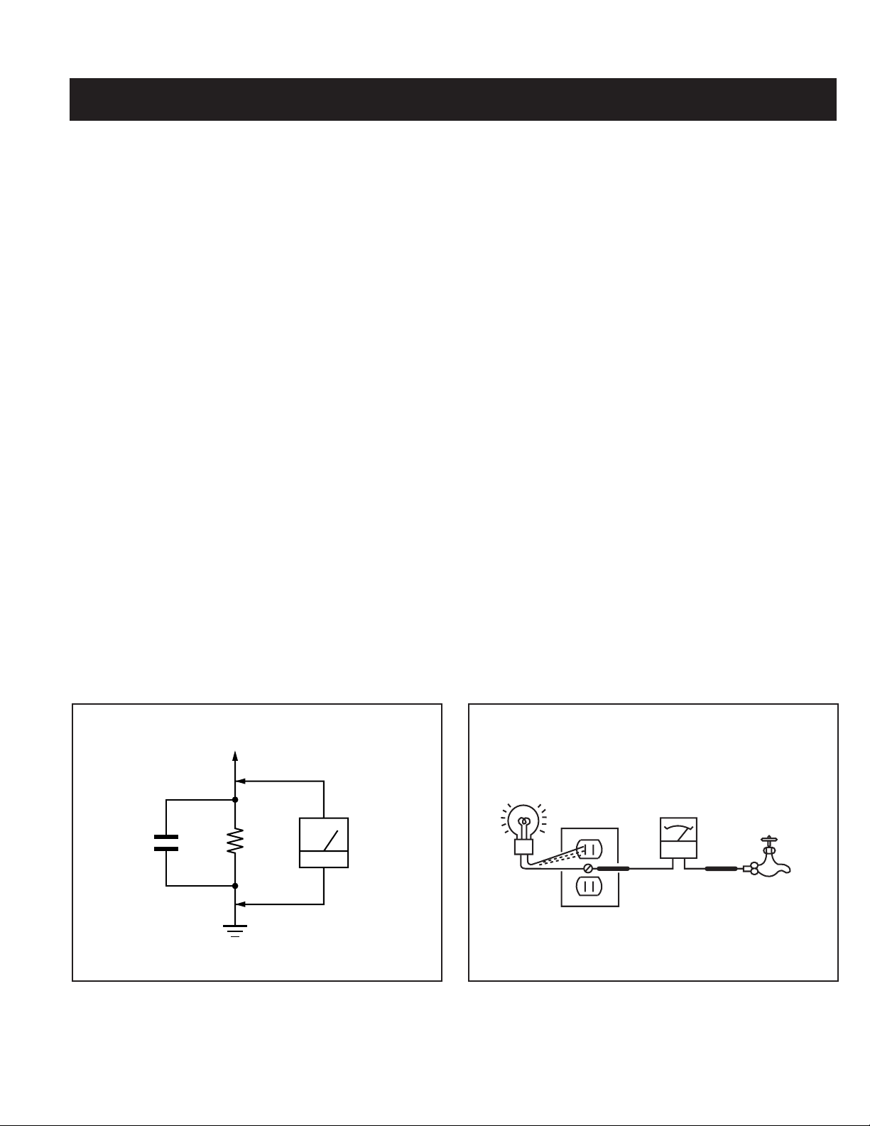
Leakage Test
The AC leakage from any exposed metal part to earth ground and from
all exposed metal parts to any exposed metal part having a return to
chassis, must not exceed 0.5 mA (500 microamperes). Leakage current
can be measured by any one of three methods.
1. A commercial leakage tester, such as the Simpson 229 or
RCA WT-540A. Follow the manufacturers’ instructions to use these
instructions.
2. A battery-operated AC milliampmeter. The Data Precision 245 digital
multimeter is suitable for this job.
3. Measuring the voltage drop across a resistor by means of a VOM
or battery-operated AC voltmeter. The “limit” indication is 0.75 V,
so analog meters must have an accurate low voltage scale. The
Simpson’s 250 and Sanwa SH-63TRD are examples of passive
VOMs that are suitable. Nearly all battery-operated digital multimeters
that have a 2 VAC range are suitable (see Figure A).
How to Find a Good Earth Ground
A cold-water pipe is a guaranteed earth ground; the cover-plate retaining
screw on most AC outlet boxes is also at earth ground. If the retaining
screw is to be used as your earth ground, verify that it is at ground
by measuring the resistance between it and a cold-water pipe with an
ohmmeter. The reading should be zero ohms.
If a cold-water pipe is not accessible, connect a 60- to 100-watt trouble-
light (not a neon lamp) between the hot side of the receptacle and the
retaining screw. Try both slots, if necessary, to locate the hot side on the
line; the lamp should light at normal brilliance if the screw is at ground
potential (see Figure B).
Figure A. Using an AC voltmeter to check AC leakage. Figure B. Checking for earth ground.

— 7 —
KV-42DRC700
SELF-DIAGNOSTIC FUNCTION
Display of STANDBY/STEREO LED Flash Count
Diagnostic items Flash count
Lamp OFF 3 sec.
Lamp ON 0.3 sec.
Lamp OFF 0.3 sec.
STANDBY/STEREO LED
+B Overcurrent (OCP) 2 times
+B Overvoltage (OVP) 3 times
Vert. Deflection Stopped 4 times
White Balance Failure 5 times
Low B OCP/OVP 6 times
Horiz. Deflection Stopped 7 times
Stopping the STANDBY/STEREO LED Flash
Turn off the power switch on the TV main unit or unplug the power cord from the outlet to stop the STANDBY/STEREO LAMP from fl ashing.
Self-Diagnostic Screen Display
For errors with symptoms such as “power sometimes shuts off” or “screen sometimes goes out” that cannot be confi rmed, it is possible to bring up
past occurrences of failure on the screen for confi rmation.
The units in this manual contain a self-diagnostic function. If an error occurs, the STANDBY/STEREO LED will automatically begin to fl ash. The number
of times the LED fl ashes translates to a probable source of the problem. A defi nition of the STANDBY/STEREO LED fl ash indicators is listed in the
instruction manual for the user’s knowledge and reference. If an error symptom cannot be reproduced, the Remote Commander can be used to review
the failure occurrence data stored in memory to reveal past problems and how often these problems occur.
Diagnostic Test Indicators
When an error occurs, the STANDBY/STEREO LED will fl ash a set number of times to indicate the possible cause of the problem. If there is more
than one error, the LED will identify the fi rst of the problem areas.
Results for all of the following diagnostic items are displayed on screen. No error has occurred if the screen displays a “0”.
No. of times STANDBY/
Diagnostic Item STEREO lamp fl ashes Display Result Probable Cause Location Detected Symptoms
Power does not turn on Does not light • Power cord is not plugged in. • Power does not come on.
• Fuse is burned out F6001 (A Board). • No power is supplied to the TV.
• AC power supply is faulty.
+B Overcurrent (OCP) 2 times 2:0 or 2:1 • H.OUT (Q5030) is shorted (D Board). • Power does not come on.
(See Note 1) • +B PWM (Q5003) is shorted (D Board). • Load on power line is shorted.
• IC9001, IC9002, IC9003 is shorted (C Board).
+B Overvoltage (OVP) 3 times 3:0 or 3:1 • IC6505 is faulty (D Board). • Has entered standby mode.
Vertical Defl ection Stopped 4 times 4:0 or 4:1 • ± 15V is not supplied (D Board). • Has entered standby state after
• IC5004 is faulty (D Board). horizontal raster.
• Vertical defl ection pulse is stopped.
• Power line is shorted or power
supply is stopped.
White Balance Failure 5 times 5:0 or 5:1 • Video OUT (IC9001-IC9003) is faulty (C Board). • No raster is generated.
(not balanced) • CRT drive (IC201) is faulty (A Board). • CRT Cathode current detection
• G2 is improperly adjusted (See Note 2). reference pulse output is small.
LOW B OCP/OVP 6 times 6:0 or 6:1 • +5 line is overloaded (A, B Boards). • No picture.
(overcurrent/overvoltage) • +5 line is shorted (A, B Boards).
(See Note 3) • IC6007 is faulty (A Board).
Horizontal Defl ection Stopped 7 times 7:0 or 7:1 • No picture.
Note 1: If a +B Overcurrent is detected, stoppage of the Vertical Defl ection is detected simultaneously. The symptom that is diagnosed fi rst by the microcontroller is displayed on screen.
Note 2: Refer to Screen (G2) Adjustment in Section 2-5. of this manual.
Note 3: If STANDBY/STEREO LED fl ashes six (6) times, unplug the unit and wait 10 seconds before performing the adjustment.
Self Diagnosis
Supported model
* One fl ash count is not used for self-
diagnostic.

— 8 —
KV-42DRC700
SELF DIAGNOSIS
2: +B OCP N/A
3: +B OVP N/A
4: V STOP 0
5: AKB 1
6: LOWB 0
7: H-STOP 0
101: WDT 24
Handling of Self-Diagnostic Screen Display
Since the diagnostic results displayed on the screen are not automatically cleared, always check the self-diagnostic screen during repairs. When you
have completed the repairs, clear the result display to “0”.
Unless the result display is cleared to “0”, the self-diagnostic function will not be able to detect subsequent faults after completion of the repairs.
Clearing the Result Display
To clear the result display to “0”, press buttons on the Remote Commander sequentially when the diagnostic screen is displayed, as shown below:
Channel
8
ENTER
Quitting the Self-Diagnostic Screen
To quit the entire self-diagnostic screen, turn off the power switch on the Remote Commander or the main unit.
Self-Diagnostic Circuit
+B Overcurrent (OCP)
Occurs when an overcurrent
(more than 6A) on the +B
(135V) line is detected by
R6598/R6591. It will cause
Q6520 to turn on and force the
AC relay to turn off through
Q6532 and Q6530.
+B Overvoltage (OVP)
Occurs when 1) overvoltage
(more than +140V) on the
+B (135V) line is detected by
IC6505, or 2) an overvoltage
(more than 7.5 V) on the unreg
7V line is detected by D6014.
The AC relay will turn off
through Q6532 and Q6530.
Vertical Defl ection Stopped
Occurs when an absence of
the vertical defl ection pulse
is detected by IC201. Power
supply will shut down when
waveform interval exceeds 2
seconds.
White Balance Failure
If the RGB levels* do not balance within 2 seconds after the power is turned on, this error will be detected by IC201. TV will stay on, but there
will be no picture.
*(Refers to the RGB levels of the AKB detection Ref pulse that detects 1K).
Low B OCP/OVP Error
Occurs when set 5V is out.
Horizontal Defl ection Stopped
Occurs when either: 1) a +B overcurrent is detected (IC5007), or 2) overheating is detected (Thermistor TH5002).
Numeral “0” means that no fault
was detected.
Numeral “1” means a fault was detected
one time only.
To Bring Up Screen Test
In standby mode, press buttons on the Remote Commander sequentially,
in rapid succession, as shown below:
DISPLAY
Channel
5
Sound volume
-
Power ON.
AKB
VPROT
HPROT
SCL
SDA
IC701
MAIN UCOM
STBY LED
HA
STR
STBY-LED
OCP
OVP
LOW B ERR
AC RLY
CLKO
DATO
29
30
69
43
45
44
48
Q6532
Q6530
D6537
D6501
Q6527
RY6501
SET ON
200V OCP
+B OCP
OVP
D8027
D8003
0
0
I
UNREG 7V
D6014
D6018
SET 5V
26
25
58
35
34
CRT
VDY -
R5125
R5104 R5105
IC5007
214
Q5018
I5V
2
1
3
OVP
Q6522
STBY 5V
Q6524
Q6521
IC6505
+B OVP
+B
Q6520
IC6007
IC201
Y/C JUNGLE
D
A
A
A
D

— 9 —
KV-42DRC700
1-1. REAR COVER REMOVAL
1-2. CHASSIS ASSEMBLY REMOVAL 1-3. SERVICE POSITION
SECTION 1: DISASSEMBLY
2
1
1
1
CAUTION! - Heat sink on IC5004 is -15V. Care must be
taken not to allow heat sink to touch any other components.
2
Gently pull the chassis assembly away from the bezel.
1
Pull up and rotate both the A and D Boards in order to
service the unit.
Remove 22 (+BVTP 4x16) screws from areas
indicated with a circle or line.
Chassis
Assembly

— 10 —
KV-42DRC700
1
Discharge the anode of the CRT and remove the
anode cap.
2
Unplug all interconnecting leads from the defl ection
yoke, neck assembly, degaussing coils and CRT
grounding strap.
3
Remove the Speaker Assemblies.
4
Remove the C Board from the CRT.
5
Remove the chassis assembly.
6
Loosen the neck assembly fi xing screw and remove.
7
Loosen the defl ection yoke fi xing screw and remove.
8
Place the set with the CRT face down on a cushion
and remove the degaussing coil holders.
9
Remove the degaussing coils.
10
Remove the CRT grounding strap and spring tension
devices.
11
Unscrew the four CRT fi xing screws [located on each
CRT corner] and remove the CRT [Take care not to
handle the CRT by the neck].
1-4. PICTURE TUBE REMOVAL
WARNING: BEFORE REMOVING THE ANODE CAP
High voltage remains in the CRT even after the power is disconnected. To avoid electric shock,
discharge CRT before attempting to remove the anode cap. Short between anode and CRT
coated earth ground strap.
Coated
Earth
Ground
Strap
ANODE CAP REMOVAL PROCEDURE
WARNING: High voltage remains in the CRT even after the power is disconnected. To avoid electric shock, discharge CRT before attempting to remove
the anode cap. Short between anode and coated earth ground strap of CRT.
NOTE: After removing the anode cap, short circuit the anode of the picture tube and the anode cap to either the metal chassis, CRT shield, or
carbon painted on the CRT.
REMOVAL PROCEDURES
HOW TO HANDLE AN ANODE CAP
1. Do not use sharp objects which may cause damage to the surface of the
anode cap.
2. To avoid damaging the anode cap, do not squeeze the rubber covering too hard.
A material fi tting called a shatter-hook terminal is built into the rubber.
3. Do not force turn the foot of the rubber cover. This may cause the shatter-hook
terminal to protrude and damage the rubber.
2
1
3
4
5
6
7
8
9
10
11
a
b
Anode Button
c
Turn up one side of the rubber cap in
the direction indicated by arrow
a
.
Use your thumb to pull the rubber
cap fi rmly in the direction indicated
by arrow
b
.
When one side of the rubber cap separates from
the anode button, the anode cap can be removed
by turning the rubber cap and pulling it in the
direction of arrow
c
.
— 11 —
KV-42DRC700
The following adjustments should be made when a complete
realignment is required or a new picture tube is installed.
These adjustments should be performed with rated power supply
voltage unless otherwise noted.
The controls and switch should be set as follows unless otherwise
noted:
VIDEO MODE: STANDARD (RESET)
SECTION 2: SET-UP ADJUSTMENTS
Perform the adjustments in order as follows:
1. Beam Landing
2. Convergence
3. Focus
4. Screen (G2)
5. White Balance
Test Equipment Required:
1. Color Bar Pattern Generator
2. Degausser
3. DC Power Supply
4. Digital Multimeter
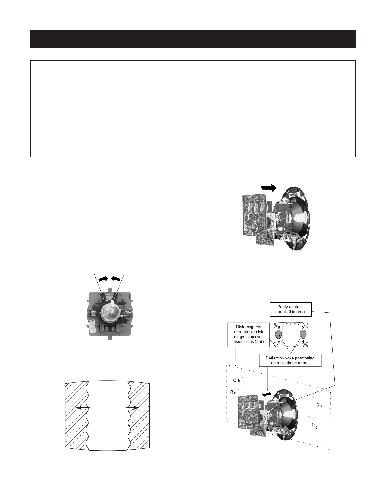
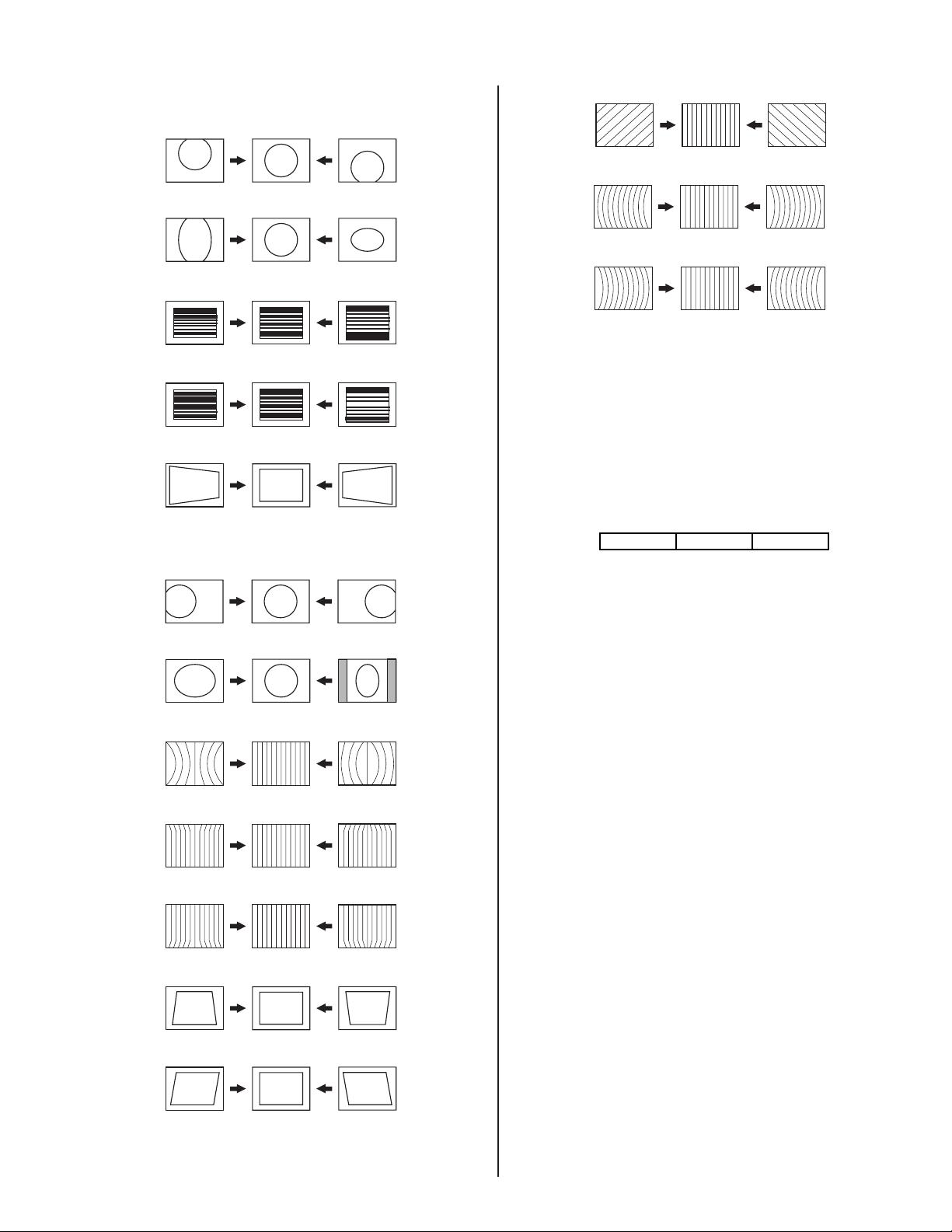
2-1. BEAM LANDING
Preparation:
• Input a white pattern signal.
• Face the picture tube in an East or West direction to reduce the
infl uence of geomagnetism.
NOTE: Do not use the hand degausser; it magnetizes the CRT .
1. Input white pattern from pattern generator. Set the PICTURE control
to maximum, and the BRIGHTNESS control to standard.
2. Perform Focus, G2 and White Balance adjustments.
3. Loosen the defl ection yoke mounting screw, and set the purity control
to the center as shown below:
Purity Control
4. Input a green pattern from the pattern generator.
5. Move the defl ection yoke backwards, and adjust with the purity control
so that green is in the center and red and blue are even on both
sides.
Blue Red
Green
6. Move the defl ection yoke forward, and adjust so that the entire screen
becomes green.
7. Switch over the raster signal to red and blue and confi rm the
condition.
8. When the position of the defl ection yoke is determined, tighten it with
the defl ection yoke mounting screw.
9. If landing at the corner is not right, adjust it by using the disk magnets.
Purity control
corrects this area.
Deflection yoke positioning
corrects these areas.
Disk magnets
or rotatable disk
magnets correct
thses areas (a-d).
b
d
a
c

— 12 —
KV-42DRC700
2-2. V-PIN AND V-CEN ADJUSTMENT
Preparation:
• Input a cross hatch pattern signal.
• Face the picture tube in a North/South direction and correct rotation.
• Set Video Mode to: Standard (Reset)
1. Adjust service mode CXA2150D-1 04 V-CEN so that the top pin and
bottom pin are symmetrical from top to bottom.
2. Adjust service mode CXA2150D-1 05 V-PIN so that the top pin and
bottom pin are symmetrical from top to bottom.
3. Lines should be straight from left to right. Check landing for side
effect.
2-3. CONVERGENGE
Preparation:
• Set the CONTRAST and BRIGHTNESS control to 50%.
• Input HD dot pattern.
2-3.1. VERTICAL AND HORIZONTAL STATIC
CONVERGENCE
1. Disconnect the dynamic convergence before adjusting static
convergence (CN5510), except for minor touch-up.
2. Adjust H.STAT convergence, RV9001, to converge red, green, and
blue dots in the center of the screen.
3. Adjust V. STAT magnet to converge red, green and blue dots in the
center of the screen.
R
G
B
Center dot
RV9001
V. S TAT
V.STAT magnet
R G B
4. Tilt the V.STAT magnet and adjust static convergence to open or close
the V.STAT magnet.
B
G
R
B
G
R
1
2-3.2. OPERATION OF BMC (HEXAPOLE)
MAGNET
The respective dot positions result from moving each magnet interact.
Perform the following adjustments while tracking.
1. Use the V.STAT tabs to adjust the red, green and blue dots so that
they line up at the center of the screen (move the dots in a horizontal
direction).
HMC Correction HMC Correction
RGB
A=B
AB
R
GB
A
>
B
AB
RGB
A=B
AB
R
GB
A
<
B
AB
VMC Correction
R
G
B
C
<
D
C
D
R
G
B
C=D
VMC Correction
R
G
B
C
<
D
C
D
R
G
B
C=D
2-3.3. TLH PLATE ADJUSTMENT
Preparation:
• Input a cross hatch pattern signal.
• Adjust PICTURE QUALITY to Standard, PICTURE and
BRIGHTNESS to 50%, and OTHER to Standard.
• Adjust unbalanced horizontal convergence of red and blue dots by
adjusting the TLH Plate on the defl ection yoke.
TLH Plate
RV9002
RV9001
W Board
C Board
TLV
XCV
TLH+
TLH-
RB
(B)(R)
BR
(R)(B)
1. Adjust XCV core to balance X axis.
2. Adjust the vertical red and blue convergence with V.TILT (TLV VR).
Note: Perform adjustments while tracking Item 1.

— 13 —
KV-42DRC700
2-3.4. SCREEN-CORNER CONVERGENCE
Preparation:
• Input a cross hatch pattern signal.
1. Affi x a permalloy assembly corresponding to the misconverged areas.
d
c
a
b
a-d: screen-corner
misconvergence
a
b
cd
2-3.5. DYNAMIC CONVERGENCE
ADJUSTMENTS
Set dynamic convergence using the following service mode adjustment
data.
NO.
Register
Function Data Length Initial Data
1 YBWU VCA9 0-63 31
2 YBWL VCA10 0-63 31
3 RSAP DC-AMP1 0-63 31
4 RUBW VCA5 0-63 31
5 RLBW VCA6 0-63 31
6 LSAP DC-AMP2 0-63 31
7 LUBW VCA10 0-63 31
8 LLBW VCA2 0-63 31
CXA8070AP
1. YBWU (Upper Y-BOW)
BR BR
2. YBWL (Bottom BOW)
BR BR
3. RSAP (Right AMP)
RB
4. RUBW (Right Side Upper C-BOW)
BR
5. RLBW (Right Side Bottom C-BOW)
RB
6. LSAP (Left AMP)
BR
7. LUBW (Left Side Upper C-BOW)
BR
8. LLBW (Left Side Bottom C-BOW)
BR
2-4. FOCUS ADJUSTMENT
1. Input a dot signal.
2. Set Video Mode to STANDARD.
3. Adjust focus VR counter-clockwise to confi rm that the dot’s shape is
centered.
4. Input a HP monoscope signal.
5. Confi rm center focus with focus VR.
FOCUS
DOT SHAPE:
2-5. SCREEN (G2)
1. Input a monoscope pattern (NTSC).
2. Set to service mode and adjust as follows:
CXA2150P-2
NO.
Disp.
Item Avg.
0 ALBK ALL_BLK 0
3. Adjust RV9002 on the C Board so that the voltage on red, green and
blue cathodes is 175 ± 2 VDC.
4. Adjust the hotizontal line at the top of the screen so it is cut off.
Note: Never set ALBK to 1 when external power supply is connected
to cathode.

— 14 —
KV-42DRC700
2-6. PICTURE QUALITY ADJUSTMENTS
Preparation:
• Set PRO MODE (Picture: MAX, GAMMA: 0).
• Dynamic-color: Off (=Trinitron: MID).
• Set the Service Mode to the following:
NO. Name Control Function Avg. Data
06 UDCL Dynamic Color: OFF 0
08 UGRAM GRAMMA 5
15 DCTR DC-TRAN 2
16 DPIC DYNAMIC PIC: OFF 1
C2150P-4
1. Input signal (480i):
• Color Bar Video 75 IRE (White) 75% modulation 7.5% Set-up.
• Color Bar RF 75 IRE (White) 75% modulation 7.5% Set-up.
2-6.1. VIDEO INPUT - TWO PICTURE SUB
CONTRAST ADJUSTMENT
Preparation:
• Input a Color Bar signal to VIDEO 1 (75 IRE 75%).
• Set picture mode: P&P (PRO MODE).
1. Set to Service Mode and adjust as follows:
NO. Name Control Function Avg. Data
00 UPIC PICTURE 63
02 UCOL COLOR 0
NO. Name Control Function Avg. Data
01 RGBS R ON 4
2150P-4
2150P-2
INITIAL DATA (IMPORTANT)
NO. Name Control Function Avg. Data
23 SCON SUB-CONT 8
NO. Name Control Function Avg. Data
00 YLEV Y-OUT 23
NO. Name Control Function Avg. Data
00 YLEV Y-OUT 23
2150P-4
2103-1
2103-2
2. Connect oscilloscope to Pin 1 of CN9001 (R.DRV) on the C Board.
3. Adjust MAIN (left) side contrast according to Service Mode for SCON.
NO. Name Control Function
02 SCON SUB-CONT
2103-1
4. Adjust SUB (right) side contrast according to Service Mode for SCON.
NO. Name Control Function
02 SCON SUB-CONT
2103-2
white
black
GND
VR2
VR1
VR1-VR2 = VR = 2.08 ± 0.05 Vp-p
5. Write data from Steps 3 and 4 above, into memory.
2-6.2. VIDEO INPUT - SUB HUE/SUB COLOR
ADJUSTMENT
Preparation:
• Input a Color Bar signal to VIDEO 1 (75 IRE 75%).
• Set picture mode: P&P (PRO MODE).
1. Set to Service Mode and adjust as follows:
NO. Name Control Function Avg. Data
00 UPIC PICTURE 63
02 UCOL COLOR 31
NO. Name Control Function Avg. Data
01 RGBS R ON 7
2150P-4
2150P-2
2. Connect an oscilloscope to Pin 5 of CN9001 (B. DRV) on the C Board.
3. Adjust MAIN (left) side color according to Service Mode for SCOL.
4. Adjust MAIN (left) side color according to Service Mode for SHUE.
NO. Name Control Function
03 SCOL SUB-COL
04 SHUE SUB-HUE
2103-1
5. Adjust SUB (right) side color according to Service Mode for SCOL.
6. Adjust SUB (right) side color according to Service Mode for SHUE.
NO. Name Control Function
03 SCOL SUB-COL
04 SHUE SUB-HUE
2103-2
— 15 —
KV-42DRC700
VB4
VB3VB2VB1
COLOR: VB1 < VB4 (=VB1 + 0~90 mV)
HUE: VB2 < VB3 (=VB2 + 0~90 mV)
(HUE: Adjust data -2 STEP)
7. Write data into memory.
2-6.3. RF INPUT - TWO PICTURE SUB
CONTRAST ADJUSTMENT
Preparation:
• Input a Color Bar signal to RF (75 IRE 75%).
• Set picture mode: P&P (PRO MODE).
1. Set to Service Mode and adjust as follows:
NO. Name Control Function Avg. Data
00 UPIC PICTURE 63
02 UCOL COLOR 0
NO. Name Control Function Avg. Data
01 RGBS R ON 4
2150P-4
2150P-2
INITIAL DATA (IMPORTANT)
NO. Name Control Function Avg. Data
23 SCON SUB-CONT 8
NO. Name Control Function Avg. Data
00 YLEV Y-OUT 23
NO. Name Control Function Avg. Data
00 YLEV Y-OUT 23
2150P-4
2103-1
2103-2
Note: Use the same average data as 2-6.1., Items 3 - 4 after the
adjustment.
2. Connect an oscilloscope to Pin 1 of CN9001 (R. DRV) on the C
Board.
3. Adjust MAIN (left) side contrast according to service mode for SCON.
NO. Name Control Function
02 SCON SUB-CONT
2103-1
4. Adjust SUB (right) side contrast according to Service Mode for SCON.
NO. Name Control Function
02 SCON SUB-CONT
2103-2
white
black
GND
VR2
VR1
VR1-VR2 = VR = 2.08 ± 0.05 Vp-p
5. Write data from Steps 3 - 4 above, into memory.
2-6.4. RF INPUT - SUB HUE/SUB COLOR
ADJUSTMENT
Preparation:
• Input a Color Bar signal to RF (75 IRE 75%).
• Set picture mode: P&P (PRO MODE).
1. Set to Service Mode and adjust as follows:
NO. Name Control Function Avg. Data
00 UPIC PICTURE 63
02 UCOL COLOR 31
NO. Name Control Function Avg. Data
01 RGBS R ON 7
2150P-4
2150P-4
INITIAL DATA (IMPORTANT)
NO. Name
Control Function
Avg. Data
24 CLOF OFFSET for UCOL 8
25 HUOF OFFSET for UHUE 4
NO. Name
Control Function
Avg. Data
01 CLEV CB & CR-OUT 20
20 CBOF CB-OFFSET 31
21 CROF CR-OFFSET 31
NO. Name
Control Function
Avg. Data
01 CLEV CB & CR-OUT 19
20 CBOF CB-OFFSET 31
21 CROF CR-OFFSET 31
2150P-4
2103-1
2103-2
Note: Use the same average data as 2-6.2., Items 3-6 after the
adjustment.
2. Connect an oscilloscope to pin 5 of CN9001 (B. DRV) on the C Board.
3. Adjust MAIN (left) side color according to Service Mode for SCOL.
4. Adjust MAIN (left) side color according to Service Mode for SHUE.
NO. Name Control Function
Avg. Data
03 SCOL SUB COLOR Adjust
04 SHUE
SUB HUE
Fix: 8
2103
-
1
5. Adjust SUB (right) side color according to Service Mode for SCOL.

— 16 —
KV-42DRC700
6. Adjust SUB (right) side color according to Service Mode for SHUE.
NO. Name Control Function Avg. Data
03 SCOL SUB COLOR Adjust
04 SHUE SUB HUE
Fix: 5
2103-2
VB4
VB3VB2VB1
COLOR: VB1 < VB4 (=VB1 + 0~90 mV)
HUE: VB2 < VB3 (=VB2 + 0~90 mV)
(HUE: Adjust data -2 STEP)
7. Write data into memory.
2-7. WHITE BALANCE (CRT) AND SUB
BRIGHT ADJUSTMENT
Preparation
• Input an all white 480I (15.734 KHz) signal into the VIDEO 1 input
terminal to perform the White Balance (highlight, cut-off) adjustments.
The parameters to adjust are in the CXA2150P in Service Mode.
1. Set the following:
Picture: Full Mode
Pro Mode
Color: Center
2. Adjust White Balance in the Service Mode and set the following data:
NO. Name Control Function Avg. Data
05 RDRV R-DRIVE Fix: 46
06 GDRV G-DRIVE Adjust
07 BDRV B-DRIVE Adjust
08 RCUT R-CUT OFF Fix: 41
09 GCUT G-CUT OFF Adjust
10 BCUT B-CUT OFF Adjust
21
5
0P
-
1
3. Adjust Sub Brightness: Input an all black signal (to IRE 7.5% set up)
480i (15.75 KHz) signal into the VIDEO 1 input terminal. Adjust the
following parameter of CXA2150P-1:
4. Check Initial Data (Important).
NO. Name Control Function Avg. Data
04 SBRT SUB-BRIGHT 20
CXA2150P-1
NO. Name Control Function Avg. Data
00 SBOT SUB-BRT OFFSET 7
12 SBOF SUB-BRT OFFSE
T
63
2150P-1
5. Repeat Steps 2-4.
2-8. RASTER CENTER ADJUSTMENT
Preparation:
• Input a monoscope signal.
• Set to NTSC (DRC) mode.
1. Set to Service Mode and adjust as follows:
NO.
Name Control Function Avg. Data
06 AGNG AGING 1, AGING 2 2
NO.
Name Control Function Avg. Data
02 HSIZ Horiz Size Adjust
NO.
Name Control Function Avg. Data
00 HBLK Blanking Enable 0
CXA2150P-2
CXA2150D-2
CXA2150D-3
2. Reduce HSIZ to see sides of raster.
3. Adjust H-Center with CXA2150D-2 00.
4. Adjust to the best screen position with H-CENT and write data.
5. Restore aging, HSIZ and HBLK to original condition.
2-9. PICTURE DISTORTION ADJUSTMENTS
2-9.1. NTSC (DRC) FULL MODE
ADJUSTMENT
1. Face the picture tube in an east-west direction.
2. Complete V-PIN and V-CEN adjsuments fi rst (A2150-D1 05 V-PIN,
A2150-D1 04 V-CEN).
3. Input a monoscope and crosshatch signal. Adjust the picture
distortion with the following service parameters to balance the best
condition for these two signals.
A2150-D1 00 VPOS
A2150-D1 01 VSIZ
A2150-D1 02 VLIN
A2150-D1 03 VSCO
A2150-D1 04 VCEN
A2150-D1 05 VPIN
A2150-D1 07 HTPZ
A2150-D2 01 HPOS
A2150-D2 02 HSIZ
A2150-D2 03 SLIN
A2150-D2 04 MPIN
A2150-D2 06 UCP
A2150-D2 07 LCP
A2150-D2 13 PPHA
A2150-D2 14 VANG
A2150-D2 15 LANG
A2150-D2 16 VBOW
A2150-D2 17 LBOW
Note: Make sure that the picture size is within specs. Vertical size is
11.7 ± 0.1 sq. and horizontal size is 15.6 ± 0.1 sq.
4. Write data into memory and then set the screen to 1080i mode.
— 17 —
KV-42DRC700
CXA2150D-1
0. VPOS (V-POSITION)
1. VSIZ (V-SIZE)
2. VLIN (V-LINE)
3. VSCO (VS-COR)
7. HTPZ (H-TRAPEZOID)
CXA2150D-2
1. HPOS (H-POSITION)
2. HSIZ (H-SIZE)
5. PIN (PIN AMP)
6. UCP (UP COR PIN COR)
7. LCP (LOW CO PIN COR)
13. PPHA (PIN PHASE)
14. VANG (AFC-ANGLE)
15. LANG (L-ANGLE)
16. VBOW (AFC-BOW)
17. LBOW (L-BOW)
2-9.2. 1080i HD MODE ADJUSTMENT
1. Input a 1080i cross-hatch signal and an HD monoscope signal that
contains overscan markers.
2. Adjust the raster position per Section 2-8., only if this procedure was
not performed for full mode.
3. Adjust the geometry similar to Full DRC mode. Vertical size is 11.7
± 0.1 sq. and horizontal size is 15.6 ± 0.1 sq., if monoscope signal is
available. Otherwise, set the Vertical size to 91.0 ± 0.6% scan and
Horizontal size as 91.0 ± 0.6% scan.
4. Use the following register to adjust the horizontal parameter:
A
2150-D2 01 HPOS
Note: If necessary, touch up the geometry using the data register
listed above for Full mode.
5. Write the data into memory.
2-9.3. VERTICAL COMPRESSED MODE
CHECK AND CONFIRMATION
1. Input a monoscope and crosshatch signal.
2. Check vertical compressed mode.

— 18 —
KV-42DRC700
SECTION 3: SAFETY RELATED ADJUSTMENTS
3-2. B+ MAX CONFIRMATION
Standard............................................................................ 135.3 ± 1 VDC
Check Condition:
AC input voltage: 120 (± 2) VAC at Board Adjustment Process
130 (± 2) VAC at QC
120 (± 2) VAC at Overall Adjustment (after aging)
Note: If using a stabilized power supply, make sure that the distortion
factor is 3% or less.
Setting Mode:........................................................................... Full mode
Signal Input:................................................ Cross-hatch of NTSC at QC
Initial Setting:........................................................ Reset condition at QC
Confi rm Point:.......................................Across C6544 for B+ of D Board
3-1. X RV8001, RV8002 CONFIRMATION METHOD AND HV SERVICE ADJUSTMENTS
3-3. HV SERVICE FLOWCHART
Is T8001
Changed?
Is D-Board
Replaced?
Replace RV8001, RV8002 with the same value:
HV project adjust and inspection
1. Turn RV8001 fully counter-clockwise.
2. Turn set on with black video signal then adjust RV8002 slowly to obtain
35.5kV.
3. Turn RV8001 clockwise slowly until hold down operation initially activates.
4. Adjust RV8002 clockwise, then turn the set on. Change video to white field then
slowly turn RV8002 counter-clockwise to get 34.8 ± 0.2kV. Confirm set does
NOT TURN OFF at this condition. If yes, then repeat from step 1 again.
5. Finally, set back RV8002 to 31.50kv + 0.2kv at video cut off (black video).
Start
No
Ye s
Change any
or
marked parts
Ye s
No
Ye s
No
Start from
the beginning.
Ye s
Is +B, Vd and
hold down
confirmed?
Finish for
hold-down
check.
Confirm +B, Vd and check hold-down on the D Board video with no signal (standard
reset mode) as follows:
1. Confirm +B across C6544 to make sure that it is 135.3 ± 1 Vdc.
2. Confirm Vd at Pin 2 CN5506 or at TP-Vd for 4.3V
<
Vd
<
4.65 Vdc.
3. Apply 5.5 ± 0.5 Vdc at Pin 2 of CN5506, then confirm that set holds down.
If all adjustments are complete, then seal and secure RV8001, RV8002 with
epoxy to prevent any possible misadjustment by non-trained technical
service.

— 19 —
KV-42DRC700
4-1. SETTING THE SERVICE ADJUSTMENT
MODE
1. Standby mode (Power off).
2. Press the following buttons on the Remote Commander within one
second of each other:
DISPLAY
Channel
5
Sound Volume
+
Power
SERVICE ADJUSTMENT MODE VIEW
2150P-1 0 +7 SERVICE
SBOT TV
Device Item Data Item
Register
Item
F/A FLAG:
CBA FLAG:
WSL: 0
READING THE MEMORY
1. Enter into Service Mode.
2. Press
0
on the Remote Commander.
3. Press
ENTER
to read memory.
ADJUSTING THE PICTURE
1. Enter into Service Mode
2. Press
2
or
5
on the remote to select the device item.
3. Press
1
or
4
on the remote to select an item.
4. Press
3
or
6
on the remote to change the data.
5. Press
MUTING
then
ENTER
to write into memory.
4-1.1. RESETTING THE DATA
Note: Be careful when using the remote! It will clear and re-initialize
ALL NVM data including defl ection adjustment data if not reset
properly as follows:
RESETTING THE DEFLECTION NVM DATA
1. Enter into Service Mode.
2. Press
7
, then
MENU
, and then press
ENTER
on the remote.
RESETTING THE SYSTEM NVM DATA
1. Enter into Service Mode.
2. Press
7
, then
9
, and then press
ENTER
on the remote.
RESETTING THE SYSTEM NVM DATA
1. Enter into Service Mode.
2. Press
8
and then press
ENTER
on the remote.
4-2. MEMORY WRITE CONFIRMATION
METHOD
1. After adjustment, pull out the plug from the AC outlet, then replace the
plug in the AC outlet again.
2. Turn the power switch ON and set to Service Mode.
3. Call the adjusted items again to confi rm they were adjusted.
4-3. REMOTE ADJUSTMENT BUTTONS AND
INDICATORS
SECTION 4: CIRCUIT ADJUSTMENTS
ELECTRICAL ADJUSTMENTS BY REMOTE COMMANDER
Use the Remote Commander (RM-Y184) to perform the circuit adjustments in this section.
Test Equipment Required: 1. Pattern generator 2. Frequency counter 3. Digital multimeter 4. Audio oscillator
RM-Y184
WRITE
INTO MEMORY
ITEM UP
ITEM DOWN
TEST
RESET
DEVICE UP
DATA UP
DATA DOWN
DEVICE DOWN
EXECUTE
READ
MEMOR
Y
— 20 —
KV-42DRC700
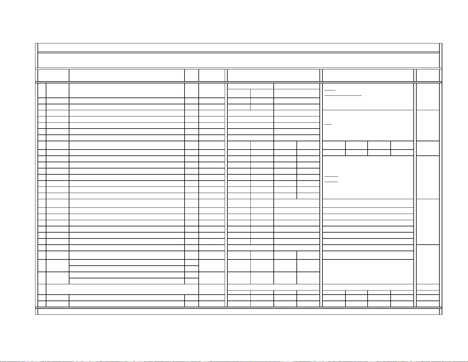
4-4. SERVICE DATA LISTS
Device Name
Device Reference
Number
Slave Address Comment
# 1 3D-COMB µPD64082 IC3501 / BC-board B8h (W) & B9h (R) W&R: Write & Read
# 2-1 CXA2103-1 (Main) IC3048 (Main) / B-board 9Ah
# 2-2 CXA2103-2 (Sub) IC3110 (Sub) / B-board 9Eh
# 3-1 CXA2150P-1
# 3-2 CXA2150P-2
# 3-3 CXA2150P-3
# 3-4 CXA2150P-4
# 4-1 CXA2150D-1
# 4-2 CXA2150D-2
# 4-3 CXA2150D-3
# 5 CXA2151 CXA2151Q IC3001 / B-board 84h
# 6 D-CON
V
CXA8070P IC5513 / D-board DEh
# 7 CXA2026 CXA2026AS IC5511 / D-board 8Eh
# 8 AP
BH3868FS
IC7001 / A-board 82h
# 9 TRUS NJM2180M IC4101 / S-board 2Eh
Controlled through CXA1315M ( IC4103 / S-board / 48h )
# 10 MID1 CXD9509AQ IC3408 / B-board 2Eh
Controlled through MID-XA Micro ( IC3090 / B-board / 64h )
# 11 MID2 CXD9509AQ IC3408 / B-board 2Eh
Controlled through MID-XA Micro ( IC3090 / B-board / 64h )
# 12 MID3 CXD9509AQ IC3408 / B-board 2Eh
Controlled through MID-XA Micro ( IC3090 / B-board / 64h )
# 13 MID5 CXD9509AQ IC3408 / B-board 2Eh
Controlled through MID-XA Micro ( IC3090 / B-board / 64h )
# 14
OSD
M306V2ME-153FP IC701 / A-board 60h DX1A-2001 S
y
stem Micro
{
V1.0
}
µPD64082 IC3501 / BC-board B8h (W) & B9h (R)
CXA2103Q IC3048 (Main) / B-board 9Ah
CXA2150Q IC201 / A-board 86h
# 16 ID1 CXD2085M IC3603 / B-board 40h
IC3602 (Main) / B-board
68h (Main)
IC3601 (Sub) / B-board
6Ch (Sub)
# 18
OP
M306V2ME-153FP IC701 / A-board 60h DX1A-2001 S
y
stem Micro
{
V1.0
}
# 19
ID
M306V2ME-153FP IC701 / A-board 60h DX1A-2001 S
y
stem Micro
{
V1.0
}
86hCXA2150Q
IC201 / A-board
IC201 / A-board
CXP85840A-039Q
SNNR
CXA2103Q
CXA2150Q 86h
DX1A-2001* Service List ------ Contents & Notes
Category Number & Name
# 15
# 17
CCD&VCHIP
CCD&Vchip Micro (V2.14)
DX1A-2001 CCD&Vchip Micro
s
MB94918RPF-G-137-BND (MASK), Software Version 12/08/00, IC3090/B-board (Slave Address: 64h)
CXP85840A-039Q (MASK), Software Version 2.14, IC3602/B-board (Main/Slave Address: 68h) & IC3601/B-board (Sub/Slave Address:
Note:
* This service list is used for DX1A-2001 ONLY. Some service data is the same in DX1A-2001 & 2000, as noted in the data sheets.
DX1A-2001 System Micro &
Notes for Services
DX1A-2001 MID-XA Micro
M306V2ME-153FP (MASK), Software Version 1.0, IC701/A-board (Slave Adress: 60h)
The system micro name, software&patch versions, and the status of NVM devices are displayed only when in the service catergory
(#19): ID.
— 21 —
KV-42DRC700
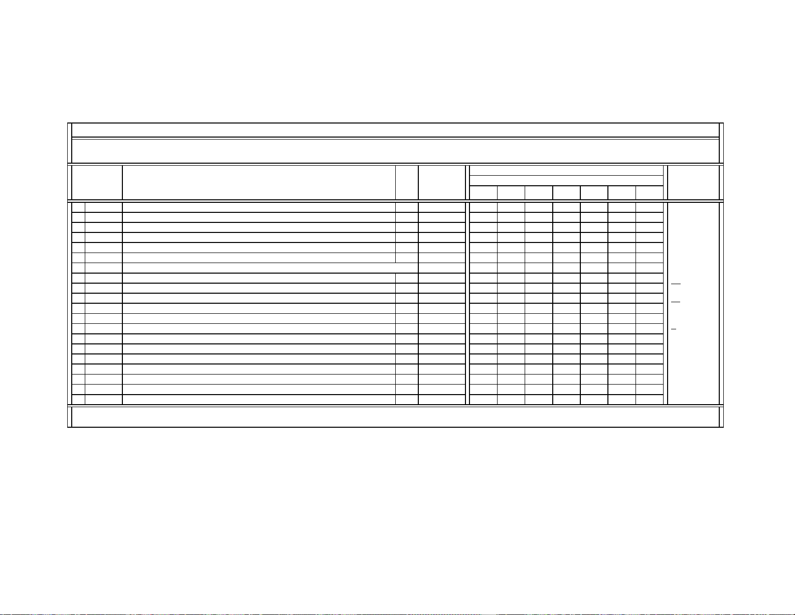
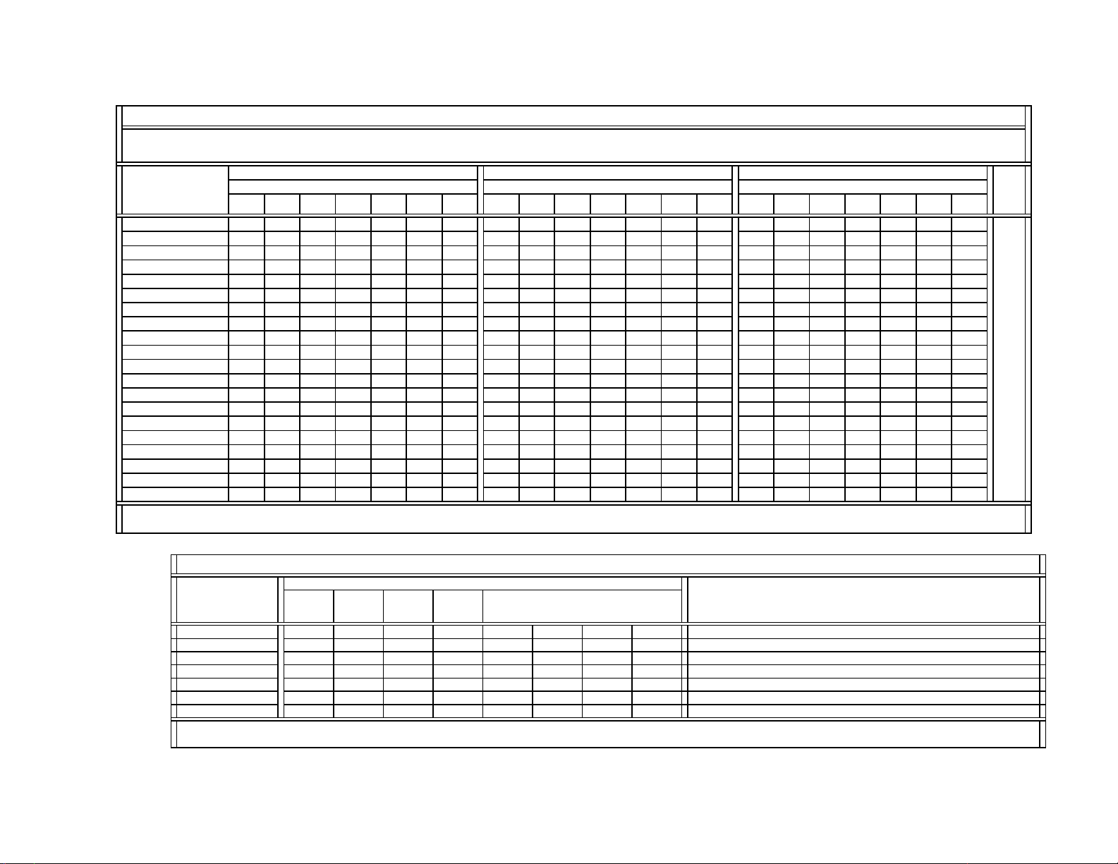
SERVICE DATA LISTS
Control Register
Function & Link
Data
Type
Data
Range
Comment
Standard
Non-standard
Standard Non-standard
0
NRMD
O
p
eration mode settin
g
0~30133
1
YAPS
Y-output correction
(
V-a
p
erture com
p
ensation & Y-
p
eakin
g
filterin
g)
C 0~3 3
2
CLKS
S
y
stem clock settin
g
C 0~3 1
Standard
Non-standard
Standard Non-standard
3
NSDS
Selection for standard/non-standard si
g
nal
p
rocessin
g
0~30000
4
MSS
Selection for inter-frame/inter-line
p
rocessin
g
C 0~3 0
5
KILS
Killer
p
rocessin
g
selection C 0~3 1
6
CDL
C-signal phase with respect to the Y-signal
(
Fine ad
j
ustment at 70 ns/ste
p)
C 0~7 3
NRMD Setting-based Control Table for DYCO, DYGA, DCCO, DCGA NRMD = 0 NRMD = 1 NRMD = 2 NRMD = 3
7
DYCO
DY detection corin
g
level
(
Y motion detection corin
g)
0~15 2222
8
DYG
A
DY detection
g
ain
(
Y motion detection
g
ain
)
0~15 10 10 10 10
9
DCCO
DC detection corin
g
level
(
C motion detection corin
g)
0~15 5555
10
DCG
A
DC detection
g
ain
(
C motion detection
g
ain
)
0~15 5555
11
Y
NRL
Frame recersive YNR nonlinear filter limit level C 0~3 1
12
CNRL
Frame recersive CNR nonlinear filter limit level C 0~3 1
UHF/VHF Video1~4 Video5&6
13
VTRH
Hysteresis for Hsync non-standard signal detection
(
out-of-Hs
y
nc intra-field
)
0~3 1 1 1
14
VTRR
Sensitivity for Hsync non-standard signal detection
(
out-of-Hs
y
nc intra-field
)
0~3 1 1 1
15
LDSR
Sensitivity for frame non-standard signal detection
(
out-of-Hs
y
nc inter-frame
)
0~3 2 2 2
VM = Off VM = Low VM = Mid VM = High
16
VAPG
V-a
p
erture com
p
ensation
g
ain 0~70234
17
VAPI
V-a
p
erture com
p
ensation conver
g
ence
p
oint 0~31 4 4 4
SNNR = 0 SNNR = 1 SNNR = 2 SNNR = 3
18
Y
PFT
Y
p
eakin
g
filter
(
BPF
)
center fre
q
uenc
y
0~30000 0
19
Y
PFG
Y
p
eakin
g
filter
(
BPF
)
g
ain 0~15 7012 3
Note: The same 3D-COMB service data is used for DX1A-2001&2000.
SVideoUHF/VHF & CVideo
DX1A-2001&2000 SERVICE LIST (#1): 3D-COMB / mPD64082 (Part-1/4)
VAPG1 Data Based on MENU/VM Setting
Device Name: mPD64082GF { 3D-Comb Filter / NEC } / IC3501 (BC-board) / P/N: 8-759-594-44 (SB#: V7372)
Slave Address: B8h (Write Address) / B9h (Read Address)
CVideo (CV): CVideo1~4 inputs
SVideo (SV)
: SVideo1~3 inputs
C
: Common data
Video1~4
: CVideo1~4 & SVideo1~3 inputs
Video5&6
: YPbPr-480i/480p/1080i inputs
Data Initial/Average Setting
(32V&36V CRTs)
Register
No & Name
SVideoUHF/VHF & CVideo
This setting continues to
the next page.
SNNR Setting-based Control Table for YPFT & YHFG
SNNR Setting (-Offset)
8
VM&SNNR Setting-based Control Table for VAPG & VAPI
VAPG= VAPG1 - VAPG2
Register
No & Name
SNNR = 0 SNNR = 1 SNNR = 2 SNNR = 3
#16 VAPG
(
cont.
)
0000
Data Initial/Average Setting
(32V&36V CRTs)
Comment
DX1A-2001&2000 SERVICE LIST (#1): 3D-COMB / mPD64082 (Part-2/4)
Note: The same 3D-COMB service data is used for DX1A-2001&2000.
VAPG2 Data Based on SNNR/Offset-setting

— 22 —
KV-42DRC700
SERVICE DATA LISTS
Control Register
Function & Link
Data
Type
Data
Range
Comment
SNNR Setting-based Control Table for YHCO & YHCG SNNR = 0 SNNR = 1 SNNR = 2 SNNR = 3
(Not SNNR Offset Dat
a
20
YHCO
Y output high frequency component coring 0~3 1 1 1 1
21
YHCG
Y output high frequency component coring gain 0, 1 0 0 0 0
22
HSSL
Hsync slice level C 0~15 12
23
VSSL
Vsync slice level C 0~15 8
24
ADCL
ADC clock delay C 0~3 3
NRMD Setting-based Control Table for D2GA NRMD = 0 NRMD = 1 NRMD = 2 NRMD = 3
25
D2GA
Moving detection gain 0~7 4 4 4 4
26
KILR
Killer detection reference C 0~15 3
27
OP1
Option1:
Selection of comb filter & recursive noise reduction t
yp
es
C 0, 1 1
UHF/VHF CVideo1 SVideo1
28
NR1
Noise reduction on/off 0, 1 0 0 1
29
NR2
SNNR control on/off C 0, 1 0
30
WSL
Noise level detection data 0~255
31
HPLL H-PLL filter
(
Must be set to 1 when MN si
g
nal is input.
)
C
0, 1 1
32
BPLL
Burst PLL filter
C
0, 1 1
33
FSCF
Burst extraction gain
C
0, 1 0
34
PLLF
PLL loop gain
C
0, 1 1
UHF/VHF Video1~4 Video5&6
35
CC3N
Selection of a line-comb filter C separation filter characteristic 0, 1 0 0 0
36
HDP
Fine adjustment of the system H-phase C 0~7 5
37
BGPS
Internal burst gate start position
{Gate Start Position from Hsync center = 0.25 x BGPS +
2
(
ms
)}
C 0~15 4
38
BGPW
Internal burst gate width
{
Gate Width = 0.25 x BGPW + 0.5
(
ms
)}
C 0~15 10
39
TEST
Test bit {0: Normal mode, 1: Test mode (forbidden settin
g
C 0, 1 0
40
WSC
Amount of noise detection coring C 0~3 1
Video5&6
41
LIND
DRC-M line-doubling setting for non-standard signals
Micro
0~63 2
42
PFGO
(YPFG offset at GR on) --- Not used for DX1A --- 0~7 3
Register
No. & Name
Data Initial/Average Setting
(32V&36V CRTs)
C: Common data
1 Byte Data from Read Register WSL
This setting is used for non-standard
signals
such as Play Station signals.
Note: The same 3D-COMB service data is used for DX1A-2001&2000.
(Not used for DX1A)
UHF/VHF & Video1~4
0
YHCO&YHCG
settings are sent
directl
y
to 3D-Comb
DX1A-2001&2000 SERVICE LIST (#1): 3D-COMB / mPD64082 (Part-3/4)
This setting continues to
the next page.
Video1~4
: CVideo1~4 & SVideo1~3
inputs
Video5&6
: YPbPr-480i/480p/1080i
Register
No & Name
CVideo2 SVideo2 CVideo3 SVideo3
#28 NR1
(
cont.
)
0101
Comment
DX1A-2001&2000 SERVICE LIST (#1): 3D-COMB / mPD64082 (Part-4/4)
Note: The same 3D-COMB service data is used for DX1A-2001&2000.
Data Initial/Average Setting
(32V&36V CRTs)
— 23 —
KV-42DRC700
SERVICE DATA LISTS
Control Register
Function & Link
Data
Type
Data
Range
Note
P&P-Left
(M)-DRC
P&P-Left
(M)-1080i
P&P-Left
(M)-DRC
P&P-Left
(M)-480i
0
Y
LEV
Y-Out
g
ain 0~63 23 27* 35 31*
1
CLEV
Cb&Cr-Out
g
ains 0~63 20 55* 37 31*
2
SCON
Sub contrast
Adj.
0~15
3
SCOL
Sub color
Adj.
0~15
4
SHUE
Sub hue Ad
j
. 0~15
5
Y
DL
Y
Y/C dela
y
time 0~3
SNNR Data-related Settings UHF/VHF CVideo SVideo
Y
PbPr
480i
SNNR=0
(
-offset
)
SNNR=1
(
-offset
)
SNNR=2
(-offset)
SNNR=3
(
-offset
)
6
SHAP
Shar
p
ness 0~15 6444 0123
7
SHF0
Shar
p
ness f0 selector 0~3 0000
8
PREO
Shar
p
ness
p
re/over-shoot ratio 0~3 3000
9
BPF0
Chroma band filter f0 settin
g
0~3 3000
10
BPFQ
Chroma band filter Q settin
g
0~3 0333
11
BPSW
Chroma band filter on/off 0, 1 1000
12
TRAP
Y bolck chroma tra
p
filter on/off 0, 1 0000
13
LPF
YPbPr-Out
p
ut LPF on/off 0, 1 0000
UHF/VHF Video
Y
PbPr
480i
14
AFCG AFC Loo
p
Gain
(
PLL between Hs
y
nc & HVCO
)
0, 1 1 0 0
15
CDMD
V countdown s
y
stem mode selector 0~3 3 3 3
16
SSMD
H&Vs
y
nc slide level settin
g
0~3 0 0 0
17
HMSK
Maskin
g
of macrovision si
g
nal on/off 0, 1 1 1 1
18
HALI
H automatic ad
j
ustment on/off 0, 1 0 0 0
19
PPH
A
H TIM
p
hase ad
j
ustment for video 0~15 7 7 7
P&P-Left
(M)-DRC
P&P-Left
(M)-1080i
P&P-Left
(M)-DRC
P&P-Left
(M)-480i
Cb-Offset1 of Cb IN (Pin34)
Cb-Offset2 of EXT Cb (Pin38)
Cr-Offset1 of Cr IN (Pin35)
Cr-Offset2 of EXT Cr (Pin39)
Single
UBLK = 0 UBLK = 1 UBLK = 2 UBLK = 3 UBLK = 4 UBLK = 5 UBLK = 6 UBLK = 7 UBLK = 0~7
22
ATPD
Auto-
p
edestal Inflection Point 0~3 0
123
1232 0
23
DCTR
DC Transmission Ratio 0~3 0
111
2223 0
Adj.: Adjusted data
[Adj.-2steps]: The adjusted data - 2 steps
CVideo
: CVideo1~4 Inputs
SVideo
: SVideo1~3 Inputs
*: Settings not used
(31): The center setting = 31
UHF/VHF
7 [7]
31*31 31* 31
CXA2150P-4/#13 UBLK Setting-related Controls for ATPD & DCTR
31*
7 [7]
Data Initial/Average Setting
(32V&36V CRTs)
Video: CVideo1~4 & SVideo1~3 Inputs
P&P-Left (M)-1080i&480i
: If P&P-Left is
1080i/480p signal, the signal from the main
chroma decoder is sent to MID/VDO input.
*: Settings not used
31*0~(31)~63
YPbPr-480i
UHF/VHF & Video
8 [Adj.-2steps]
UHF/VHF & Video
0
Video
7 [7]
7 [7]
7 [Adj.-2steps]
0
P&P & Favorite
CBOF
3131
CROF
0~(31)~63
YPbPr-480i
P&P & Favorite
Note: The same CXA2103 service data (Main&Sub) is used for DX1A-2001&2000.
20
21
Register
No & Name
Data Initial Setting & [Average Data]
(32V&36V CRTs)
DX1A-2001&2000 SERVICE LIST (#2-1):
CXA2103-1 {Main}
Device Name: CXA2103Q { NTSC-YCT (Chroma Decoder) / SONY } / IC3048 (B-board) / P/N: 8-752-089-50 (SBorSD#: NA)
Slave Address: 9Ah { Main }
— 24 —
KV-42DRC700
SERVICE DATA LISTS
Control Register
Function & Link
Data
Type
Data
Range
Note
P&P-Right
(S)
P&P-Right
(S)-DRC
0
Y
LEV
Y-Out
g
ain 0~63 23 28
1
CLEV
Cb&Cr-Out
g
ains 0~63 18 24
2
SCON
Sub contrast
Adj.
0~15
3
SCOL
Sub color
Adj.
0~15
4
SHUE
Sub hue Ad
j
. 0~15
5
Y
DL
Y
Y/C dela
y
time 0~3
SNNR Data-related Settings UHF/VHF CVideo SVideo
SNNR=0
(
-offset
)
SNNR=1
(
-offset
)
SNNR=2
(-offset)
SNNR=3
(
-offset
)
6
SHAP
Shar
p
ness 0~15 6 4 4 0 1
2
3
7
SHF0
Shar
p
ness f0 selector 0~3 0 0 0
8
PREO
Shar
p
ness
p
re/over-shoot ratio 0~3 3 0 0
9
BPF0
Chroma band filter f0 settin
g
0~3 0 0 0
10
BPFQ
Chroma band filter Q settin
g
0~3 0 0 0
11
BPSW
Chroma band filter on/off 0, 1 0 0 0
12
TRAP
Y bolck chroma tra
p
filter on/off 0, 1 0 0 0
13
LPF
YPbPr-Out
p
ut LPF on/off 0, 1 0 0 0
UHF/VHF Video
14
AFCG AFC Loo
p
Gain
0, 1 1 0
15
CDMD
V countdown s
y
stem mode selector 0~3 3 3
16
SSMD
H&Vs
y
nc slide level settin
g
0~3 0 0
17
HMSK
Maskin
g
of macrovision si
g
nal on/off 0, 1 1 1
18
HALI
H automatic ad
j
ustment on/off 0, 1 0 0
19
PPH
A
H TIM
p
hase ad
j
ustment for video 0~15 7 7
P&P-Right
(S)
P&P-Right
(S)-DRC
P&P-Right
(S)
P&P-Right
(S)-DRC
Cb-Offset1 of Cb IN
(
Pin34
)
Cb-Offset2 of EXT Cb
(
Pin38
)
Cr-Offset1 of Cr IN
(
Pin35
)
Cr-Offset2 of EXT Cr
(
Pin39
)
Single
UBLK = 0 UBLK = 1 UBLK = 2 UBLK = 3 UBLK = 4 UBLK = 5 UBLK = 6 UBLK = 7 UBLK = 0~7
22
ATPD
Auto-
p
edestal Inflection Point 0~3 0
123
12
3
20
23
DCTR
DC Transmission Ratio 0~3 0
111
22
2
30
Note: The same CXA2103 service data (Main&Sub) is used for DX1A-2001&2000.
00
7 [7] 7 [7]
UHF/VHF Video
7 [7]
Data Initial/Average Setting
(32V&36V CRTs)
Device Name: CXA2103Q { NTSC-YCT (Chroma Decoder) / SONY } / IC3110 (B-board) / P/N: 8-752-089-50 (SBorSD#: NA)
Slave Address: 9Eh { Sub }
Register
No & Name
DX1A-2001&2000 SERVICE LIST (#2-2):
CXA2103-2 {Sub}
7 [7]
31* 31*
UHF/VHF & CVideo
31*310~(31)~63
31 31
21
CROF
0~(31)~63
YPbPr-480i
31*
CBOF
UHF/VHF & Video
Data Initial Setting & [Average Data]
(32V&36V CRTs)
P&P & Favorite P&P & Favorite
20
5 [Adj.-2steps] 7 [Adj.-2steps]
Adj.: Adjusted data
[Adj.-2steps]: The adjusted data - 2 steps
*: Settings not used
(31): The center setting = 31
CVideo
: CVideo1~4 Inputs
SVideo
: SVideo1~3 Inputs
31
Video
: CVideo1~4 & SVideo1~3 Inputs
P&P-Right (S)-DRC
: If P&P-Left is 1080i/
480p signal, the signal from the sub chroma
decoder is switched to DRC path.
CXA2150P-4/#13 UBLK Setting-related Controls for ATPD & DCTR

— 25 —
KV-42DRC700
SERVICE DATA LISTS
Control Register
Function & Link
Data
Type
Data
Range
Comment
UHF
V
HF
CV SV
YPbPr
480i
YPbPr
480
p
YPbPr
1080i
P&P
0 SBOT Offset for SBRT 0~
(
7
)
~157777777
1 YOF Y_OFFSET: DC-offset for Y si
g
nal 0~
(
7
)
~150000000
2 CBOF CB_OFFSET: DC-offset for Cb si
g
nal
0~(31)~63
31 31 31 33 30 31 13
3 CROF CR_OFFSET: DC-offset for Cr si
g
nal
0~(31)~63
31 31 31 42 36 31 23
4 SBRT SUB_BRIGHT: Sub Bri
g
h
t
0~63
5 RDRV R_DRIVE: R out
p
ut drive C
0~63
6 GDRV G_DRIVE: G out
p
ut drive Ad
j
.
0~63
7 BDRV B_DRIVE: B out
p
ut drive Ad
j
.
0~63
8 RCUT R_CUTOFF: R out
p
ut cutof
f
C
0~63
9 GCUT G_CUTOFF: G out
p
ut cutof
f
Ad
j
.
0~63
10 BCUT B_CUTOFF: B out
p
ut cutof
f
Ad
j
.
0~63
Pro
11 WBSW
WB_SW: White balance offset on/off
(
Related to UTMP settin
g
s
)
0, 1
0
12 SBOF Offset for SBRT 0~
(
63
)
~127 63
13 RDOF Offset for RDRV 0~
(
63
)
~127 63
14 GDOF Offset for GDRV 0~
(
63
)
~127 63
15 BDOF Offset for BDRV 0~
(
63
)
~127 63
16 RCOF Offset for RCUT 0~
(
63
)
~127 63
17 GCOF Offset for GCUT 0~
(
63
)
~127 63
18 BCOF Offset for BCUT 0~
(
63
)
~127 63
Data Initial Settings & [Average Data]
(32V&36V CRTs)
Register
No & Name
1
(Warm)
63
MovieVivid
0
(Cool)
46
36 [36]
Device Name: CXA2150AQ { CRT Driver / SONY } / IC201 (A-board) / P/N: 8-752-093-35 (SBorSD#: NA)
Slave Address: 86h
DX1A-2001&2000 SERVICE LIST (#3-1):
CXA2150P-1 {Picture Controls: P1}
20 [20]
63
63**
63
33 [33]
66**
63
0
(Neutral)
63
Standard
63
63**
66**
41
63 60
63
63
63
11 [11]
22 [22]
73**
75**
Note:
The same CXA2150 service data is used for DX1A-2001&2000.
63
CV:
CVideo1~4
SV
:
SVideo1~3
( ): Settings at
center
Adj.
:
Adjusted data
C
:
Common data
Initial Setting
= [Avg. Data]
63
63
60
**: The color
temperature
offset data

— 26 —
KV-42DRC700
SERVICE DATA LISTS
Control Register
Function & Link
Data
Type
Data
Range
Comment
0 ALBK
PIC_ON: RGB output including AKB reference pulse on/of
f
(
Settin
g
= 0 for
p
ower on reset
)
--- G2 ad
j
ustment re
g
ister settin
g
C 0, 1 1
1 RGBS
R_ON/G_ON/B_ON: R/G/B outputs on/of
f
(
AKB reference
p
usle can not be turned on/off.
)
(
0
,
1/0
,
1/0
,
1
)
C 0~7 7
2 BLKB
BLK_BTM: RGB output bottom limit level (Black Limit)
(
AKB reference
p
usle DC-volta
g
e
)
C 0~3 3
3 LIML PLIMIT_LEV: Threshold level for excessivel
y
hi
g
h in
p
uts
(
White Limi
t
C 0~3 0
4 PABL P_ABL: DC-level in RGB out
p
ut detection for PEAK ABL C
0~15
15
5 SABL S_ABL: S_ABL
g
ain C 0~3 0
6 AGNG
AGING_W/AGING_B: AGING_W/AGING_B modes on/of
f
(
Set luminance to 80/01IRE flat-field si
g
nal.
)
C
0~3
(
0
,
1/0
,
1
)
0
7 AKBO AKBOFF: Automatic/Manual-Cutoff settin
g
C 0, 1 0
YPbPr
480i
YPbPr
480
p
YPbPr
1080i
P&P
8 SYPH SYNC_PHASE: Hs
y
nc dela
y
with res
p
ect to Video
(
100%: H-
p
eriod
)
0~3 0000
9 CLPH CLP_PHASE: Internal clam
p
p
ulse
p
hase
(
100%: H-
p
eriod
)
0~3 3333
10 CLG
A
CLP_GATE: Switch for the
g
ated internal clam
p
p
ulse with Hs
y
nc in
p
u
t
0, 1 0000
11 JAXS JAXIS: Color axis switch 0, 1
12 BLKO BLKO: Blankin
g
switch 0, 1
0
3
Video1~4:
CVideo1~4 &
SVideo1~3
Note:
The same CXA2150 service data is used for DX1A-2001&2000.
U/VHF &
Video1~4
C:
Common data
0
Data Initial/Average Settings
(32V&36V CRTs)
0
Register
No & Name
DX1A-2001&2000 SERVICE LIST (#3-2):
CXA2150P-2 {Picture Controls: P2}
Device Name: CXA2150AQ { CRT Driver / SONY } / IC201 (A-board) / P/N: 8-752-093-35 (SBorSD#: NA)
Slave Address: 86h
0
— 27 —
KV-42DRC700
SERVICE DATA LISTS
UHF
V
HF
CV SV
YPbPr
480i
YPbPr
480p
YPbPr
1080i
P&P
0 SYSM SYSTEM: Si
g
nal bandwidth settin
g
0~3 1111122
1 UVML VM_LEV: VM_OUT level
C
0~3 3
2 VMMO S
y
stem Micro
p
in#40 0, 1 0000000
3 VMCR VM_COR: VM_OUT corin
g
level 0~3 3333333
4 VMLM VM_LMT: VM_OUT limit level 0~3 3333333
5 VMF0 VM_F0: VM_f0 0~3 2222222
6
V
MDL VM_DLY: VM_OUT
p
hase
(
defined b
y
p
hase difference from R_OUT
)
0~3 3333313
7 SHOF Offset for USHP = SHOF x 4 0~3 2223302
8 SHF0 SHP_F0: Shar
p
ness circuit f0 0, 1 1111101
9 PROV PRE/OVER: Y si
g
nal
p
re/over-shoot ratio 0~3 3331303
10 F1LV SHP_F1: Shar
p
ness for hi
g
her f0
(
4.2/5.6 MHz
@
NORMAL mode
)
0~3 0333333
11 CDSP SHP_CD: Shar
p
ness in
p
art of hi
g
h color saturation 0~3 3333333
12 LTLV LTI_LEV: Luminance transient im
p
rovement
(
LTI
)
0~3 3333333
13 LTMD LTI_MODE: LTI mode settin
g
0~3 0000001
14 CTLV CTI_LEV: Chrominance transient im
p
rovement
(
CTI
)
0~3 0000020
15 CTMD CTI_MODE: CTI mode settin
g
0~3 0000000
16 UBOF Offset for UBRT
(
Picture clarit
y
ad
j
ustment
)
0~
(
7
)
~15 11 11 11 11 11 14 11
17 UCOF Offset for UCOL = UCOF x 2
(
Picture clarit
y
ad
j
ustment
)
0~3 3333303
18 UHOF Offset for UHUE
(
Picture clarit
y
ad
j
ustment
)
0~3 2222222
19 MIDE MID enhancement settin
g
0~15 333711------
Comment
Picture Mode: Vivid
Data Initial/Average Settings (32V&36V CRTs)
Device Name: CXA2150AQ { CRT Driver / SONY } / IC201 (A-board) / P/N: 8-752-093-35 (SBorSD#: NA)
Slave Address: 86h
Data
Range
Control Register
Function & Link
These settings
continue to
the next page.
CV
:
CVideo1~4
SV
:
SVideo1~3
C
:
Common data
( ): Settings at
center
Data
Type
Note:
The same CXA2150 service data are used for DX1A-2001&2000.
Register
No & Name
DX1A-2001&2000 SERVICE LIST (#3-3):
CXA2150P-3 {Picture Controls: P3} (Part-1/3)
— 28 —
KV-42DRC700
SERVICE DATA LISTS
UHF
VHF
CV SV
YPbPr
480i
YPbPr
480p
YPbPr
1080i
P&P
UHF
V
HF
CV SV
YPbPr
480i
YPbPr
480p
YPbPr
1080i
P&P
UHF
VHF
CV SV
YPbPr
480i
YPbPr
480p
YPbPr
1080i
P&P
#0 SYSM
(
cont.
)
1111122 1111122 1111122
#1 UVML
(
cont.
)
300
#2 VMMO
(
cont.
)
0000000 0000000 0000000
#3 VMCR
(
cont.
)
3333333 3333333 3333333
#4 VMLM
(
cont.
)
3333333 3333333 3333333
#5 VMF0
(
cont.
)
2222222 2222222 2222222
#6 VMDL
(
cont.
)
1333313 1111113 1111113
#7 SHOF
(
cont.
)
0333302 0333303 0111101
#8 SHF0
(
cont.
)
0111101 0000001 0000001
#9 PROV
(
cont.
)
3331303 3331303 3331303
#10 F1LV
(
cont.
)
0333333 0000003 0000003
#11 CDSP
(
cont.
)
3333333 0000000 0000000
#12 LTLV
(
cont.
)
2222223 0000000 0000000
#13 LTMD
(
cont.
)
1111111 1111001 1111001
#14 CTLV
(
cont.
)
0000020 0000000 0000000
#15 CTMD
(
cont.
)
0000000 0000000 0000000
#16 UBOF
(
cont.
)
7777777 7777777 7777777
#17 UCOF
(
cont.
)
3333303 0000000 0000000
#18 UHOF
(
cont.
)
2222222 0000000 0000000
#19 MIDE
(
cont.
)
222610------ 11159------ 00048------
See
next
page
Picture Mode: Standard
Data Initial/Average Settings (32V&36V CRTs) Data Initial/Average Settings (32V&36V CRTs)
DX1A-2001&2000 SERVICE LIST (#3-3): CXA2150P-3 {Picture Controls: P3} (Part-2/3)
Note
Note:
The same CXA2150 service data are used for DX1A-2001&2000.
Data Initial/Average Settings
(32V&36V CRTs)
Register
No & Name
Picture Mode: Movie Picture Mode: Pro
#1 UVML
(
cont.
)
0000
#3 VMCR
(
cont.
)
0 + 1 + 2 + 3
#10 F1LV
(
cont.
)
0 - 1 - 2 - 3
#11 CDSP
(
cont.
)
0000
#12 LTLV
(
cont.
)
0000
#14 CTLV
(
cont.
)
0000
#19 MIDE
(
cont.
)
0000
Register
No & Name
Note:
The same CXA2150 service data are used for DX1A-2001&2000.
Data Initial/Average Settings
(32V&36V CRTs)
Comment
SNNR=0
(Offset)
SNNR=1
(Offset)
SNNR=2
(Offset)
SNNR=3
(Offset)
DX1A-2001&2000 SERVICE LIST (#3-3): CXA2150P-3 {Picture Controls: P3} (Part-3/3)

— 29 —
KV-42DRC700
SERVICE DATA LISTS
Control Register
Function & Link
Data
Type
Data
Range
Comment
Pro
0 UPIC PICTURE: Picture
0~63
31
1 UBRT BRIGHT: Bri
g
htness
0~63
31
2 UCOL COLOR: Colo
r
0~63
31
3 UHUE HUE: Hue
0~63
31
SNNR Setting-related Controls for USHP
4 USHP SHARPNESS: Sharpness 0~63 31
5 UTMP Color Tem
p
erature
(
0: Warm, 1: Neutral, 2: Cool
)
0~2 1
6 UDCL DCOL: D
y
namic color settin
g
0~3 2
YPbPr
480i
YPbPr
480p
YPbPr
1080i
7 AXIS COL_AXIS: Color matrix settin
g
0~3 3 3 3
YPbPr
480i
YPbPr
480p
YPbPr
1080i
8 UGAM
G
A
MM
A
/G
A
MM
A_
L
:
RGB
output
G
A
MM
A correct
i
on sett
i
ng
(B
7~6
)
GAMMA
_
L: Sli
g
ht GAMMA correction on/off
(
B
)
0~7
(
0~3/0
,
1
)
777
9 AGAM GAMMA/GAMMA_L (Av Pro user control) --- Void Data
0~7
(
0~3/0
,
1
)
---
UGAM Setting-related Controls for GSBO, GCOO, GHUO
UGAM
= 7
UGAM
= 6
UGAM
= 5
UGAM
= 4
UGAM
= 3
UGAM
= 2
UGAM
= 1
10 GSBO
Offset for SBRT
(
8 t
yp
es of GSBO data based on UGAM values
)
0~3 0000000
11 GCOO Offset for UCOL 0~3 0000000
12 GHUO Offset for UHUE 0~3 0000000
YPbPr
480i
YPbPr
480p
YPbPr
1080i
13 UBLK Item # 15~18
p
ack FI data controls 0~7 7 7 7
14 ABL
K
(
Av Pro user control
)
--- Void Data --- 0~7
UBLK Setting-related Controls for DCTR
15 DCTR
DC_TRAN: Y signal DC transmission
(
8 t
yp
es of DCTR data based on UBLK values
)
0~3 3 3 3
16 DPIC DPIC_LEV: Y si
g
nal AUTO PEDESTAL level 0~3 2 2 2
17 DSBO Offset for SBRT 0~
(
7
)
~15 7 7 7
18 ABLM ABL_MODE: ABL mode 0~3 1 1 1
31
35
26
50
1
1
These settings
continue to
the next page.
( ): Settings at
center
This setting
continues to
the next page.
These settings
continue to
the next page.
2
77
77
P&P
UHF/VHF
Video1~4
P&P
Picture Mode: Vivid
UHF/VHF
Video1~4
3
2
Picture Mode: Vivid / Standard / Movie
0 (Void data)
3
0
P&P
UHF/VHF
Video1~4
2
42
2
40V
34
Register
No & Name
31
Standard
7
2
1
3
7
Picture Mode: Vivid
2
1
48
Device Name: CXA2150AQ { CRT Driver / SONY } / IC201 (A-board) / P/N: 8-752-093-35 (SBorSD#: NA) Slave Address: 86h
Device Name: CXD2085M { ID-1 Decoder / SONY } / IC3603 (B-board) / P/N: 8-752-395-13 (SD#: S98511B) Slave Address: 40h
DX1A-2001&2000 SERVICE LIST (#3-4): CXA2150P-4 {Picture Controls: P4} (Part-1/4)
40V
28
Movie
31
22
34
These settings
continue to
the next page.
Video1~4
:
CVideo1~4 &
SVideo1~3
Settings for
36V CRTs
are used for
initial
settings.
Data Initial/Average Settings
(32V&36V CRTs)
Vivid
33
31
40V
63
Note:
The same CXA2150 service data are used for DX1A-2001&2000.

— 30 —
KV-42DRC700
SERVICE DATA LISTS
Register
No & Name
Note
SNNR Setting
(
-Offset
)
SNNR
= 0
SNNR
= 1
SNNR
= 2
SNNR
= 3
#4 USHP
(
cont.
)
0134
YPbPr
480i
YPbPr
480p
YPbPr
1080i
#7 AXIS
(
Cont.
)
333
YPbPr
480i
YPbPr
480p
YPbPr
1080i
YPbPr
480i
YPbPr
480p
YPbPr
1080i
YPbPr
480i
YPbPr
480p
YPbPr
1080i
#8 UGAM (Cont.) 222 000 000
UGAM
= 0
#10 GSBO
(
cont.
)
0
#11 GCOO
(
cont.
)
0
#12 GHUO
(
cont.
)
0
YPbPr
480i
YPbPr
480p
YPbPr
1080i
YPbPr
480i
YPbPr
480p
YPbPr
1080i
YPbPr
480i
YPbPr
480p
YPbPr
1080i
#13 UBLK
(
Cont.
)
444 111 000
#15 DCTR (Cont.
)
222 111 111
#16 DPIC
(
Cont.
)
111 111 000
#17 DSBO
(
Cont.
)
777 777 777
#18 ABLM
(
Cont.
)
111 000 000
Note:
The same CXA2150 service data are used for DX1A-2001&2000.
Data Initial/Average Settings
(32V&36V CRTs)
Picture Mode: Standard
Picture Mode: Standard
22
3
P&P
Data Initial/Average Settings
(32V&36V CRTs)
Data Initial/Average Settings
(32V&36V CRTs)
DX1A-2001&2000 SERVICE LIST (#3-4): CXA2150P-4 {Picture Controls: P4} (Part-2/4)
00
U/VHF
Video1~4
Picture Mode: Pro
P&P
3
UHF/VHF
Video1~4
UHF/VHF
Video1~4
4
2
1
1
1
7
1
4
0
1
Picture Mode: Pro
UHF/VHF
Video1~4
0
7
0
P&P
Picture Mode: Movie
UHF/VHF
Video1~4
7
P&P
P&P
0
7
00
See
next
pages
1
Picture Mode: Movie Picture Mode: Pro
001
P&P
U/VHF
Video1~4
2 0
P&P
U/VHF
Video1~4
0
7
1
1
7
1
11
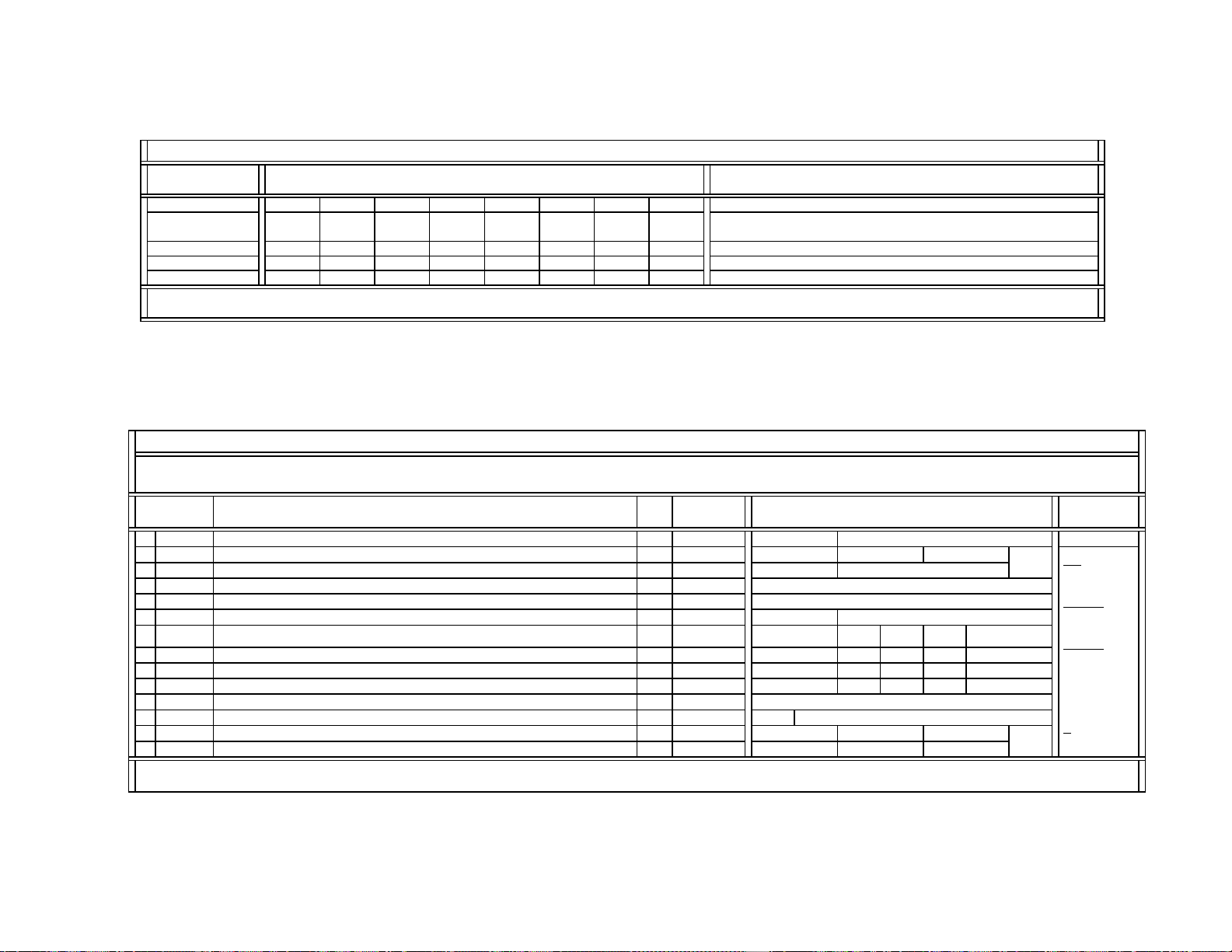
— 31 —
KV-42DRC700
SERVICE DATA LISTS
Register
No & Name
Comment
UBLK = 7 UBLK = 6 UBLK = 5 UBLK = 4 UBLK = 3 UBLK = 2 UBLK = 1 UBLK = 0
#15 DCTR (Cont.) 32221111
#16 DPIC
(
Cont.
)
23213210
#17 DSBO
(
Cont.
)
77777777
#18 ABLM
(
Cont.
)
10010000
Note:
The same CXA2150 service data are used for DX1A-2001&2000.
Data Initial/Average Settings
(32V&36V CRTs)
DX1A-2001&2000 SERVICE LIST (#3-4): CXA2150P-4 {Picture Controls: P4} (Part-3/4)
Control Register
Function & Link
Data
Type
Data
Range
Comment
19 ABL
T
ABL_TH: ABL correct detection Vth control
0~15
20 ABLC Control of CXA2026
{
0Ch -- DAC0
}
(
*
)
0~255
21 EPOF Offset for UPIC = EPOF x
(
UPIC/63
)
(
for
p
ower save
)
--- Void Data ---
0~31
ID-1 and P&P Modes
22 SPOF Offset for UPIC = SPOF x
(
UPIC/64
)
--- Data Not Used ---
0~31
YPbPr
480i
YPbPr
480p
YPbPr
1080i
23 SCON SUB_CONTRAST: SUB PICTURE
0~15
464
24 CLOF Offset for UCOL 0~
(
7
)
~15 10 9 7
25 HUOF Offset for UHUE
0~7~15
333
CXD2085 Service Controls
26 IDSW Switch for activatin
g
the selection in #27 DATA C 0, 1 0
27 DAT
A
Selection of
g
eometr
y
-forced vertical com
p
ression modes
C 0~3
0
UHF/VHF
Video1~4
Vcomp1
P&P
Full
8
Vcomp2
8
0 (Not used)
66
4
Note:
The same CXA2150 service data are used for DX1A-2001&2000.
DX1A-2001&2000 SERVICE LIST (#3-4): CXA2150P-4 {Picture Controls: P4} (Part-4/4)
Full:
480p/960i
(4x3)
Vcomp1
:
480p/960i
(16x9)
Vcomp2
:
1080i
(16x9)
( ): Settings at
center
C
:
Common data
Data Initial/Average Settings
(32V&36V CRTs)
Register
No & Name
0
0
2
8
Full
8
1
Vcomp1 Vcomp2
4
Loading...