

Sony KP-46C70, KP-48S70, KP-48S72, KP-53N74, KP-53S70 Service manual
SERVICE MANUAL
RA-3
CHASSIS
MODEL COMMANDER DEST. CHASSIS NO.
–––––– –––––––––––– ––––– –––––––––––
KP-43T70
KP-43T70
KP-46C70
KP-46C70
KP-48S70
KP-48S70
KP-48S72
RM-Y906 US SCC-P14GA
RM-Y906 Canadian SCC-P14GA
RM-Y906 US SCC-P14JA
RM-Y906 Canadian SCC-P14JA
RM-Y906 US SCC-P14HA
RM-Y906 Canadian SCC-P14HA
RM-Y906 US SCC-P14KA
MODEL COMMANDER DEST. CHASSIS NO.
–––––– –––––––––––– ––––– –––––––––––
KP-48S72
KP-53N74
KP-53N74
KP-53S70
KP-53S70
KP-61S70
KP-61S70
RM-Y906 Canadian SCC-P14KA
RM-Y906 US SCC-P14EA
RM-Y906 Canadian SCC-P14EA
RM-Y906 US SCC-P14DA
RM-Y906 Canadian SCC-P14DA
RM-Y906 US SCC-P14FA
RM-Y906 Canadian SCC-P14FA
DVD/
SAT/
POWER
MUTING
VTR
CABLE
TV
FUNCTION
SYSTEM
OFF
DVD/VTR SAT/CABLE
TV
TV/VTR
FREEZE
SWAP PIP
m
N
M
AUDIO
POSITION ACTIVE
X
xz
ANT
TV/VIDEO
SLEEP
PICTURE
DISPLAYMTS/SAP
CC
MODE
2
1
3
5
6
4
8
7
9
JUMP
ENTER
0
INDEX
GUIDE
RESET
MENU
VOL CH
CODE SET
TV
RM-Y906
MICROFILM
∗ Please file according to model size. .......
43
46
48
53 61
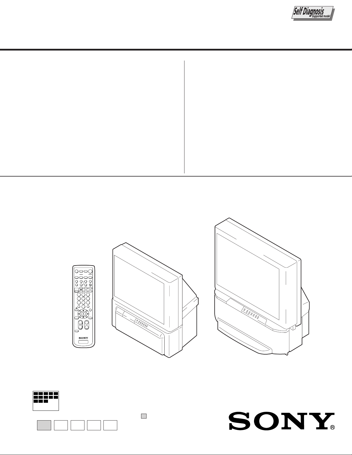
KP-43T70 KP-46C70/48S70/48S72/53N74/
53S70/61S70
COLOR REAR VIDEO PROJECTOR

KP-43T70/46C70/48S70/
48S72/53N74/53S70/61S70
RM-Y906
SPECIFICATIONS
Projection system
3 picture tubes, 3 lenses, horizontal in-line system
Picture tube
7-inch high-brightness monochrome tubes (6.3 raster size),
with optical coupling and liquid cooling system
Projection lenses
High performance, large diameter hybrid lens F1.05
Television system
American TV standard
Channel coverage
VHF: 2–13/UHF: 14 –69/CATV: 1 – 125
Antenna
75 ohm external terminal for VHF/UHF
Screen size (measured diagonally)
43 inches (KP-43T70)
46 inches (KP-46C70)
48 inches (KP-48S70/48S72)
53 inches (KP-53S70/53N74)
61 inches (KP-61S70)
Inputs/outputs
VIDEO 1 IN
VIDEO 2 INPUT
S VIDEO IN (4-pin mini DIN):
Y: 1 Vp-p, 75-ohms unbalanced, sync negative
C: 0.286 Vp-p (Burst signal), 75 ohms
VIDEO (phono jack): 1 Vp-p, 75-ohms unbalanced, sync
negative
AUDIO (phono jacks): 500 mVrms (100% modulation),
Impedance: 47 kilohms
VIDEO 3 IN
S VIDEO IN (4-pin mini DIN):
Y: 1 Vp-p, 75-ohms unbalanced, sync negative
C: 0.286 Vp-p (Burst signal), 75 ohms
VIDEO (phono jack): 1 Vp-p, 75-ohms unbalanced, sync
negative
Y: 1 Vp-p, 75 ohms, sync negative
PB: 0.7 Vp-p, 75 ohms
PR: 0.7 Vp-p, 75 ohms
AUDIO (phono jacks): 500 mVrms (100% modulation),
Impedance: 47 kilohms
MONITOR OUT
VIDEO (phono jack): 1 Vp-p, 75-ohms unbalanced, sync
negative
AUDIO (phono jacks): 470 mVrms (100% modulation),
Impedance: 47 kilohms
AUDIO (VAR/FIX) OUT (phono jacks): 500 mVrms (100%
modulation)
CONTROL S OUT: minijack
Speaker
For KP-53N74
5
Tweeter: 66 mm (2
Woofer: 130 mm (5
/8”) x 2
1
/8”) x 2
For KP-43T70/46C70/48S70/48S72/53S70/61S70
100 mm (4”) x 2
Speaker output
15W x 2 (KP-43T70/46C70/48S70/48S72/53S70/61S70)
20 W x 2 (KP-53N74)
Power requirement
120 V AC, 60 Hz
Power consumption
In use (Max.): 160 W
In standby: 1 W
Dimensions (W/H/D)
5
965 x 1,058 x 510 mm (38 x 41
/8 x 20 1/8 inches)
(KP-43T70)
7
1,064 x 1,310 x 572 mm (41
/8 x 51 5/8 x 22 1/2 inches)
(KP-46C70)
1
1,105 x 1,338 x 579 mm (43
/2 x 52 5/8 x 22 3/4 inches)
(KP-48S70)
1
1,105 x 1,338 x 579 mm (43
/2 x 52 5/8 x 22 3/4 inches)
(KP-48S72)
7
1,216 x 1,417 x 632 mm (47
/8 x 55 3/4 x 24 7/8 inches)
(KP-53S70)
1,216 x 1,417 x 632 mm (47
7
/8 x 55 3/4 x 24 7/8 inches)
(KP-53N74)
1,370 x 1,560 x 670 mm (54 x 61
3
/8 x 26 3/8 inches)
(KP-61S70)
Mass
64.6 kg (141 lbs 10 oz) (KP-43T70)
61.6 kg (135 lbs 13 oz) (KP-46C70)
64 kg (141 lbs 2 oz) (KP-48S70)
67 kg (147 lbs 11 oz) (KP-48S72)
67.6 kg (149 lbs) (KP-53S70)
75.2 kg (165 lbs 13 oz) (KP-53N74)
84.6 kg (186 lbs 8 oz) (KP-61S70)
Supplied accessories
Remote control RM-Y906 (1)
Batteries (2) size AA (R6)
Optional accessories
Connecting cables
RK-G34, RK-74A, RK-G69HG, VMC-10HG,
VMC-720M, VMC-810S/820S, YC-15V/30V
U/V mixer EAC-66
Design and specifications are subject to change without notice.
– 2 –
SAFETY CHECK-OUT
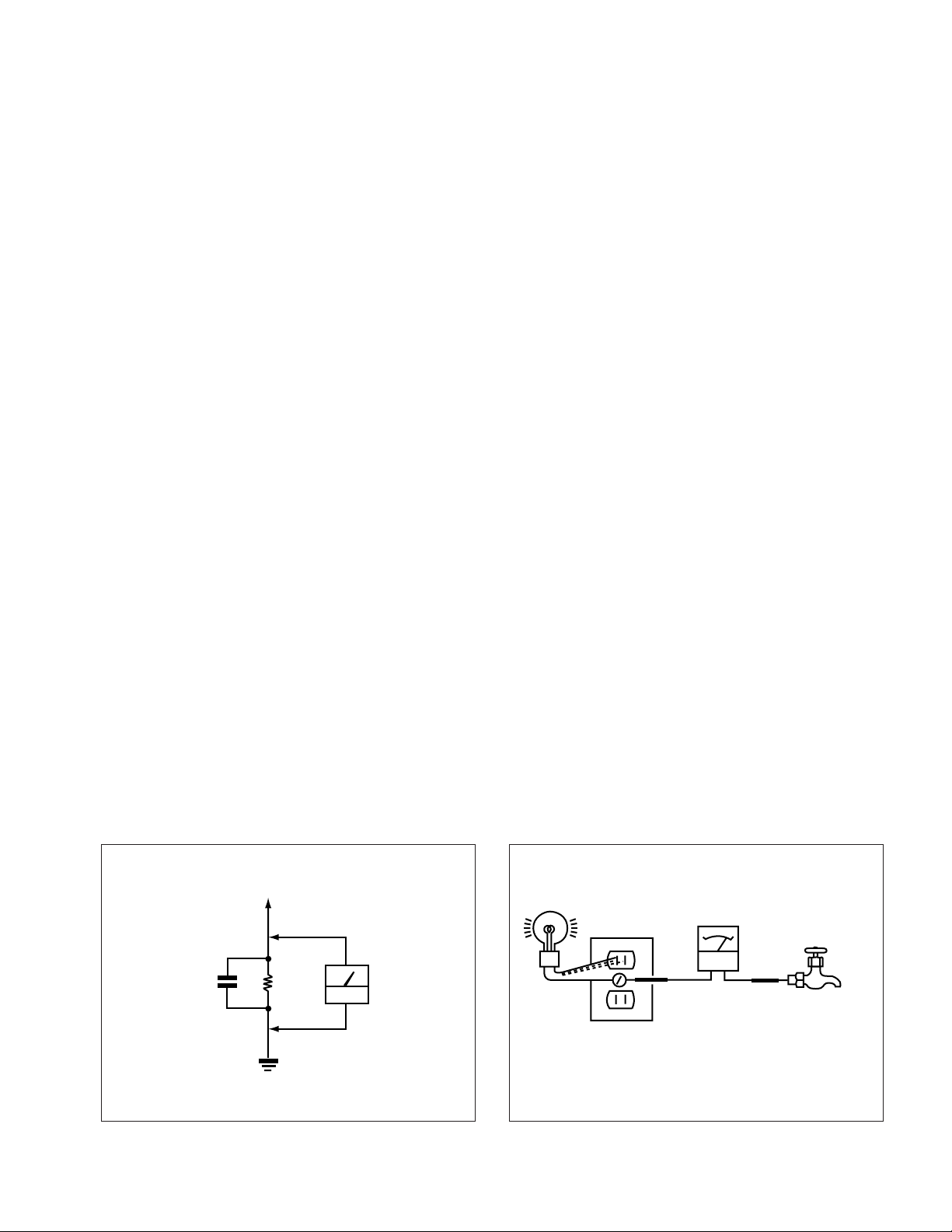
Fig. B. Checking for earth ground.
Trouble Light
AC Outlet Box
Ohmmeter
Cold-water Pipe
( US model only )
KP-43T70/46C70/48S70/
48S72/53N74/53S70/61S70
RM-Y906
After correcting the original service problem, perfom the follow-
ing safety checks before releasing the set to the customer:
l. Check the area of your repair for unsoldered or poorly-sol-
dered connections. Check the entire board surface for solder
splashes and bridges.
2. Check the interboard wiring to ensure that no wires are
“pinched” or contact high-wattage resistors.
3. Check that all control knobs, shields, covers, ground straps,
and mounting hardware have been replaced. Be absolutely
certain that you have replaced all the insulators.
4. Look for unauthorized replacement parts, particularly transistors, that were installed during a previous repair. Point them
out to the customer and recommend their replacement.
5. Look for parts which, through functioning, show obvious
signs of deterioration. Point them out to the customer and
recom mend their replacement.
6. Check the line cords for cracks and abrasion. Recommend
the replacement of any such line cord to the customer.
7. Check the condition of the monopole antenna (if any). Make
sure the end is not broken off, and has the plastic cap on it.
Point out the danger of impalement on a broken antenna to
the customer, and recommend the antenna’s replacement.
8. Check the B+ and HV to see they are at the values specified.
Make sure your instruments are accurate;be suspicious of
your HV meter if sets always have low HV.
9. Check the antenna temminals, metal trim, “metallized” knobs,
screws, and all other exposed metal parts for AC leakage.
Check leakage as described below.
LEAKAGE TEST
The AC leakage from any exposed metal part to earth ground and
from all exposed metal parts to any exposed metal part having a
return to chassis, must not exceed 0.5mA (500 microampers) . Leakage current can be measured by any one of three methods.
1. A commercial leakage tester, such as the Simpson 229 or
RCA WT-540A. Follow the manufacturers’ instructions to
usc these instruments.
2. A battery-operated AC milliammeter . The Data Precision 245
digital multimeter is suitable for this job.
3. Measuring the voltage drop across a resistor by means of a
VOM or battery-operated AC voltmeter. The “limit” indication is 0.75V, so analog meters must have an accurate lowvoltage scale. The Simpson 250 and Sanwa SH-63Trd are
examples of a passive VOM that is suitable. NearIy all battery operated digital multimeters that have a 2V AC range
are suitable. (See Fig. A)
HOW TO FIND A GOOD EARTH GROUND
A cold-water pipe is guaranteed earth ground;the cover-plate retaining screw on most AC outlet boxes is also at earth ground. If
the retaining screw is to be used as your earth-ground, verify that it
is at ground by measuring the resistance between it and a coldwater pipe with an ohmmeter. The reading should be zero ohms. If
a cold-water pipe is not accessible, connect a 60-l00 watts trouble
light (not a neon lamp) between the hot side of the receptacle and
the retaining screw. Try both slots, if necessary, to locate the hot
side of the line, the lamp should light at normal brilliance if the
screw is at ground potential. (See Fig. B)
Fig. A. Using an AC voltmeter to check AC leakage.
1.5
µ
F
To Exposed Metal
Parts on Set
1.5k
Ω
Earth Ground
AC
voltmeter
(0.75V)
– 3 –
KP-43T70/46C70/48S70/
48S72/53N74/53S70/61S70
RM-Y906
SELF DIAGNOSIS FUNCTION
1. Summary of Self-Diagnosis Function
• This device includes a self-diagnosis function.
• In case of abnormalities, the TIMER/STANDBY indicator automatically blinks. It is possible to predict the abnormality location
by the number of blinks. The Instruction Manual describes blinking of the TIMER/STANDBY indicator.
• If the symptom is not reproduced sometimes in case of a malfunction, there is recording of whether a malfunction was generated
or not. Operate the remote command to confirm the matter on the screen and to predict the location of the abnormality.
2. Diagnosis Items and Prediction of Malfunction Location
• When a malfunction occurs the TIMER/STANDBY indicator only blinks for one of the following diagnosis items. In case of two
or more malfunctions, the item which first occurred blinks. If the malfunctions occurred simultaneously, the item with the lower
blink count blinks first.
• The screen display displays the results regarding all the diagnosis items listed below. The display “ 0 ” means that no malfunctions occurred.
metisisongaiD
NOtonrewoP•0
noitcetedPCOB+semit2.tiucrichcaenimetsysylppusrewopfotiucrictrohS
noitcetedPVOB+semit3
potsnoitcelfedlacitreVsemit4
noitcetedytilamronbatuooediVsemit5
potsnoitcelfedlatnoziroHsemit6
noitcetedytilamronbaoiduAsemit8
YBDNATS/REMIT
retacidnI
sknilbforebmuN
.nepo106F
.nepo706R
.nepo276R
.tiucric
noitcnuflamdesoppuSnoitidnoC
tiucrictrohs106Q
]metsySylppuSrewoPniaM[
.nekorbera216Rdna106CI
tiucric-trohs106RDV
.nepo87nip306T
.nekorbsi)tuoV(9051CI
)draobA(022,912,812Q
.nepo615,515C
.nekorbsi)elgnuJCY(602CI
.nepo204,104SP
]metsySylppuSrewoPybdnatS[
.nekorbsi)reffuBesluPV(5051Q
.nekorbsi).pmaoiduA(604CI
sisongaid-fleS
,yalpsidneercs
stluseR:metisisongaiD
.rewopehtnonruttonnaC
.knilbt'nseodDEL
edomybdnatsehtotseoG
enilB+fotiucrictrohS
edomybdnatsehtotseoG
tiucricylppusrewopfonoitcnuflaM
.detumsilangis
draobCnisrehtodna167,237,507Q,tuooediV
.sisongaidflesehtrofsknilbnehtdna
.raeppat'nseodretsaR000potSH:6
.tuotonsidnuosehT
edomybdnatsehtotseoG
oedivnehtdnaA,yllatnozirohenilenootseogretsaR
,sdnoces03.xorppasknilbDELYBDNATS/REMIT
000PCOB+:2
000PVOB+:3
000potSV:4
000BKA:5
000oiduA:8
* : 000 the range of values for number of operations is 000-255. For 256 or higher there is
no count up and the number remains at 255.
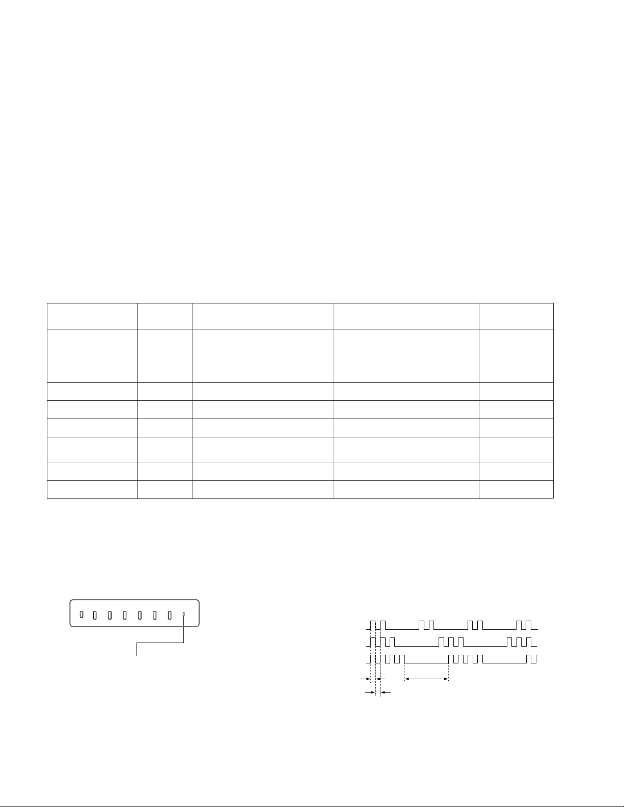
3. Blinking count display of TIMER/STAVDBY indicator
* One blink is not used for self-diagnosis.
< FRONT PANEL >
VOLUME
–+
TV/VIDEO
FLASH FOCUS
CHANNEL
–+
POWER
•EXAMPLE
TIMER/STAND BY
<Diagnosis Items> <Number of Blinks>
• +B overcurrent 2 times
• +B overvoltage 3 times
TIMER/STANDBY indicator
• Vertical deflection stop 4 times
Lamp ON : 0.3 seconds
Lamp OFF : 0.3 seconds
Release of TIMER/STANDBY indicator blinking.
• The TIMER/STANDBY indicator blinking display is released by turning OFF the power switch
on the TV main unit or removing the plug from the power.
– 4 –
Lamp OFF :
3.0 seconds
KP-43T70/46C70/48S70/
48S72/53N74/53S70/61S70
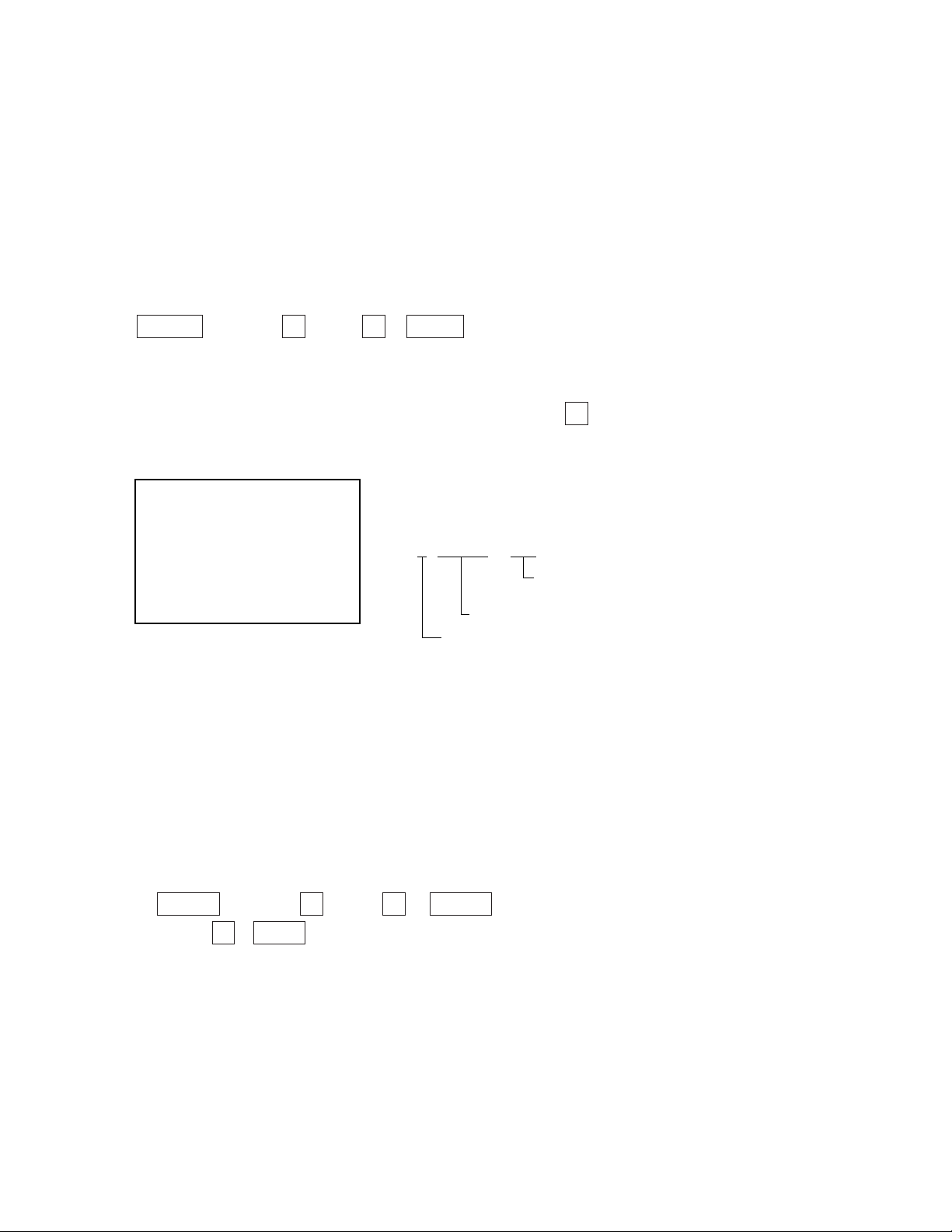
4. Self-diagnosis screen displays
• In cases of malfunctions where it is not possible to determine the symptom such as when the power goes off occasionally or when
the screen disappears occasionally, there is a screen display on whether the malfunction occurred or not in the past (and whether
the detection circuit operated or not) in order to allow confirmation.
<Screen Display Method>
• Quickly press the remote command button in the following order from the standby state.
DISPLAY b Channel 5 b VOL – b POWER
˘
Be aware that this differs from the method of
entering the service mode (volume + ).
Self-diagnosis screen display
RM-Y906
Self Check
2 : +B OCP 000
3 : +B OVP 000
4 : V Stop 000
5 : AKB 000
6 : H Stop 000
7 : HV 000
8 : Audio 000
101 : WDT 000
÷
2 : +B OCP 000
Diagnosis
Results
000 the range of values for number of
operations is 000-255.
For 256 or higher there is no count up
and the number remains at 255.
5. Self-Diagnosis Screen Display
• The results display is not automatically cleared. In case of repairs and after repairs, check the self-diagnosis screen and be sure
to return the results display to “ 0 ”.
• If the results display is not returned to “ 0 ” it will not be possible to judge a new malfunction after completing repairs.
<Method of Clearing Results Display>
1. Power off (Set to the standby mode)
2. DISPLAY b Channel 5 b VOL + b POWER (Service Mode)
3. Channel 8 b ENTER (Test reset = Factory preset condition)
<Method of Ending Self Diagnosis Screen>
• When ending the self-diagnosis screen completely, turn the power switch OFF on the remote commander or the main unit.
– 5 –
KP-43T70/46C70/48S70/
48S72/53N74/53S70/61S70
RM-Y906
6. Self-diagnosis function operation
OCP Low B and +B line detect DET SHORT, and shut-down POWER ON RELAY.
Reset by turning power on/off.
In case of +B is loaded approx. 1.3A or more, microcomputer detects it via IC651.
OVP In case of +B becomes approx. 150V or more, POWER ON RELAY shuts down and microcomputer detects it via IC651.
Reset by turning power on/off just the same as OCP.
V Stop In case of microcomputer detects 2 seconds or more interval of V Pulse, Reference Pulse turns off by turning off the picture
signal in YC Jungle IC (IC206).
After the picture signal turns off, V Pulse is regenerated 2 seconds or more, the picture signal turns on.
AKB IK detection. Makes LED blinking in case of microcomputer doesn’t detect IK returns of IC206 CXA2147Q 30 seconds or more.
H Stop In case of HV becomes 33kV or more, IC502 detects it and shut-down H Drive Pulse.
Microcomputer receives H Stop data from IC206 and makes LED blinking.
Audio In case of DC component overlaps the output of Audio Amp., microcomputer detects it and makes LED blinking.
Microcomputer forces to shut down the power.
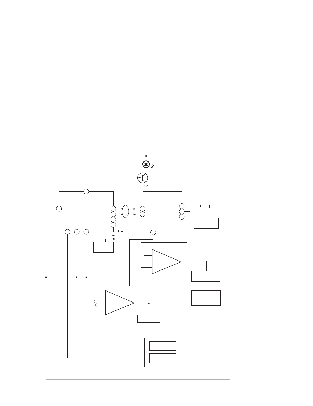
Self-diagnosis block diagram
8
20 21 22
55
IC002
µProcessor
TIMER/STANDBY
IC064
EEPROM
Audio AMP
5. AKB
6. H STOP
49
47
50
48
IC406
D1201
BUS
5. AKB
Q006
3
4
IC206
CXA2147
YCJ
43
35
34
6. HV STOP
IC1502
HV Detector
27
IC1509
V Drive
Q1505
V Pulse Buffer
C Board
4. V.STOP (V Pulse)
3. OVP
2. OCP
Audio
IC651
OVP Buffer
OCP Buffer
DC Detect
OVP DETECT
OCP DETECT
– 6 –

TABLE OF CONTENTS
KP-43T70/46C70/48S70/
48S72/53N74/53S70/61S70
RM-Y906
Section Title Page
–––––– –––– ––––
SELF DIAGNOSIS FUNCTION............................................ 4
1. GENERAL
Remote Control ....................................................................... 9
Precautions .............................................................................. 9
Installing and Connecting the Projection TV ........................ 10
Basic Set Up .......................................................................... 15
Using Your New Projection TV ............................................ 16
Adjusting Your SET UP (menus) .......................................... 19
Operating Video Equipment.................................................. 30
Operating a Cable Box or Satellite Receiver (SAT).............. 31
Troubleshooting .................................................................... 31
2. DISASSEMBLY
2-1. Rear Board Removal ................................................. 33
2-2. Chassis Assy Removal .............................................. 33
2-3. Service Position ......................................................... 33
2-4. HA Board and HB Board Removal
(Except KP-43T70) ................................................... 33
2-5. HA Board and HB Board Removal(KP-43T70) ....... 34
2-6. Mirror Cover Removal .............................................. 34
2-7. Beznet Assy Removal ............................................... 34
2-8. HC Board and S Board Removal .............................. 34
2-9. A Board and G Board Removal ................................ 35
2-10. Picture Tube Removal ............................................... 35
2-11. High-Voltage Cable Installation and Removal.......... 35
3. SET-UP ADJUSTMENTS
3-1. Screen Voltage Adjustment (Rough Alignment) ....... 36
3-2. Focus Lens Adjustment ............................................. 36
3-3. Screen (G2) Adjustment ............................................ 36
3-4. Focus VR Adjustment ............................................... 36
3-5. Deflection York Tilt Adjustment ............................... 37
3-6. 2-Pole Magnet Adjustment (Green, Red) .................. 37
3-7. 4-Pole Magnet Adjustment........................................ 37
3-8. Defocus Adjustment (Blue) ....................................... 37
3-9. Electrical Adjustment by Remote Commander ......... 38
3-10. Registration Adjustment ............................................ 43
3-11. Auto Registration Error Code List ............................ 46
4. SAFETY RELATED ADJUSTMENTS
4-1. HV Regulation Circuit Check and Adjustment ......... 47
4-2. HV Hold Down Circuit Operation and Adjustment .. 47
4-3. +B Max Voltage Confirmation .................................. 47
4-4. +B OVP Confirmation .............................................. 48
Section Title Page
–––––– –––– ––––
5. CIRCUIT ADJUSTMENTS
5-1. TV Input Sub Contrast Adjustment
(VPNT-SCON) .......................................................... 49
5-2. Video Input Sub-HUE and Sub-Color Adjustment .......
(VPNT-SHUE, SCOL) .............................................. 49
5-3. Component Input Sub-HUE and SubColorAdjustment
(DAC-UVSH, UVSC) ............................................... 49
5-4. P & P Sub Contrast Adjustment (SC-SYDR)............ 49
5-5. Sub-HUE, Sub-Color and Main Contrast Adjustment ..
(MC-MYDR, MSHU, MSCL, SC-SSHU, SSCL) .... 50
5-6. Bar Display Position Adjustment (OP-DISP) ........... 50
5-7. PIP Position Adjustment (PI-PIPH, PIPV)................ 50
7. DIAGRAMS
6-1. Block Diagram (1)..................................................... 51
Block Diagram (2)..................................................... 53
Block Diagram (3)..................................................... 59
Block Diagram (4)..................................................... 63
Block Diagram (5)..................................................... 65
6-2. Frame Schematic Diagram ........................................ 67
6-3. Circuit Boards Location ............................................ 70
6-4. Printed Wiring Boards and Schematic Diagrams ...... 70
• A (1/3)Board ........................................................... 71
• A (2/3)Board ........................................................... 75
• A (3/3)Board ........................................................... 79
• G Board................................................................... 87
• CG Board ................................................................ 94
• CR Board ................................................................ 95
• CB Board ................................................................ 95
• HA Board ................................................................ 97
• HC Board ................................................................ 97
• HB Board ................................................................ 98
6-5. Semiconductors ......................................................... 99
7. EXPLODED VIEWS
7-1. Cover (KP-43T70) .................................................. 101
7-2. Cover (KP-46C70/48S70/48S72)............................ 102
7-3. Cover (KP-53N73/53S70/61S70) ........................... 103
7-4. Chassis (KP-43T70) ................................................ 104
7-5. Chassis (Except KP-43T70) .................................... 105
7-6. Picture Tube ............................................................ 106
8. ELECTRICAL PARTS LIST ................................. 107
– 7 –

KP-43T70/46C70/48S70/
48S72/53N74/53S70/61S70
RM-Y906
SHORT CIRCUIT THE ANODE OF THE PICTURE TUBE AND THE
(CAUTION)
ANODE CAP TO THE METAL CHASSIS, CRT SHIELD, OR CARBON PAINTED ON THE CRT, AFTER REMOVING THE ANODE.
WARNING!!
AN ISOLATION TRANSFORMER SHOULD BE USED DURING
ANY SERVICE TO AVOID POSSIBLE SHOCK HAZARD, BECAUSE OF LIVE CHASSIS.
THE CHASSIS OF THIS RECElVER IS DIRECTL Y CONNECTED
TO THE AC POWER LINE.
SAFETY-RELATED COMPONENT WARNING!!
COMPONENTS IDENTIFIED BY SHADING AND MARK ! ON THE
SCHEMATIC DIAGRAMS, EXPLODED VIEWS AND IN THE
PARTS LIST ARE CRITICAL TO SAFE OPERATION. REPLACE
THESECOMPONENTS WITH SONY P ARTS WHOSE PART NUMBERS APPEAR AS SHOWN IN THIS MANUAL OR IN SUPPLEMENTS PUBLISHED BY SONY. CIRCUIT ADJUSTMENTS THAT
ARE CRITICAL T O SAFEOPERATION ARE IDENTIFIED IN THIS
MANUAL. FOLLOW THESE PROCEDURES WHENEVER CRITICAL COMPONENTS ARE REPLACED OR IMPROPER OPERATION IS SUSPECTED.
APRES A VOIR DECONNECTE LE CAP DE L ’ANODE, COUR TCIR-
(ATTENTION)
CUITER L’ANODE DU TUBE CATHODIQUE ET CELUI DE
L’ANODE DU CAP AU CHASSIS METALLIQUE DE L’APPAREIL,
OU AU COUCHE DE CARBONE PEINTE SUR LE TUBE CATHOD-
IQUE OU AU BLINDAGE DU TUBE CATHODIQUE.
ATTENTION!!
AFIN D’EVITER TOUT RISQUE DELECTROCUTION PROVENANT D’UN CHÁSSIS SOUS TENSION, UN TRANSFORMA TEUR
D’ISOLEMENT DOIT ETRE UTILISÉ LORS DE TOUT DEPANNAGE.
LE CHÁSSIS DE CE RECEPTEUR EST DIRECTEMENT RACCORDÉ Á L’ALIMENTATION SECTEUR.
ATTENTION AUX COMPOSANTS RELATIFS ÁLA
SÉCURITÉ!!
LES COMPOSANTS IDENTIFIÉS PAR UNE TRAME ET PAR UNE
MAPQUE ! SUR LES SCHÉMAS DE PRINCIPE, LES VUES EX-
PLOSÉES ET LES LISTES DE PIECES CONT D’UNEIMPORTANCE
CRITIQUE POUR LA SÉCURITÉ DU FONCTIONNEMENT. NE LES
REMPLACER QUE PAR DES COMPOSANTS SONY DONT LE
NUMÉRO DE PIÉCE EST INDIQUÉ DANS LE PRÉSENT MANUEL OU DANS DES SUPPLÉMENTS PUBLIÉS PAR SONY. LES
RÉGLAGES DE CIRCUIT DONT L’IMPOR TANCE EST CRITIQUE
POUR LA SÉCURITÉ DU FONCTIONNEMENT SONT IDENTIFIES
DANS LE PRÉSENT MANUEL. SUIVRE CES PROCÉDURES
LORS DE CHAQUE REMPLACEMENT DE COMPOSANTS CRITIQUES, OU LORSQU’UN MAUVAIS FONCTIONNEMENT EST
SUSPECTÉ.
– 8 –
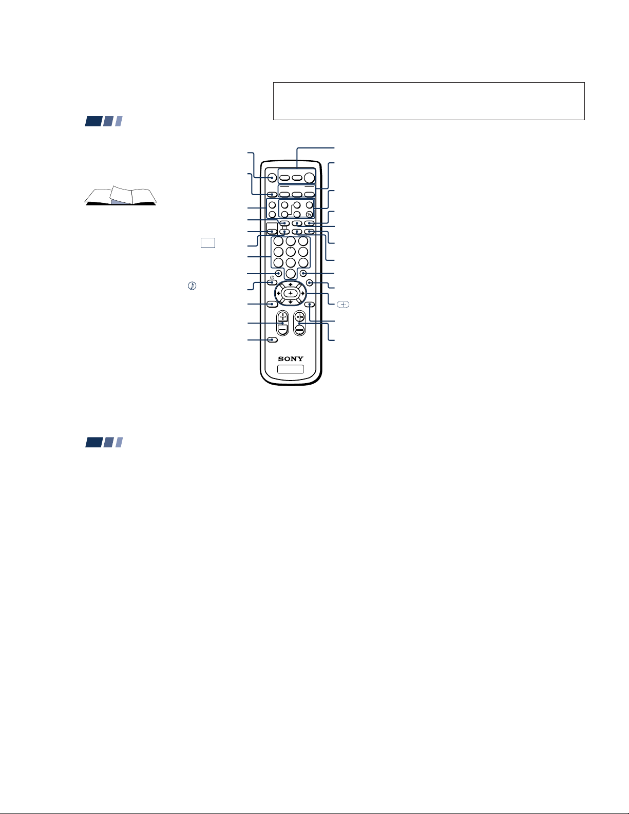
Remote Control
SECTION 1
GENERAL
The operating instructions mentioned here are partial abstracts from the
Operating Instructions Manual. The page numbers of the Operating
Instruction Manual remain as in the manual. (Part no : 3-866-565-11)
In the instructions that follow, we will
refer to the buttons on your remote control.
Keep this flap unfolded and use this page
for reference.
VCR/DVD/MDP
operation buttons
SLEEP
PICTURE MODE
0 – 9 buttons
JUMP
(for SAT, page 45)
INDEX
(pages 19, 22, 23)
VOL +/–
MUTING
(page 16)
SYSTEM OFF
(page 18)
(page 44)
(page 18)
(pages 16, 22)
CC
(page 18)
(page 16)
(page 17)
(pages 18, 23)
RESET
(page 16)
CODE SET
(pages 43, 45)
POWER
(pages 16, 44, 45)
TV
TV
M
FUNCTION
(pages 16, 44, 45)
PIP operation
buttons
(page 19)
TV/VIDEO
(pages 17, 19)
ANT
(page 20)
DISPLAY
(page 17)
MTS/SAP
(pages 18, 23)
ENTER
(page 16)
GUIDE
(page 45)
V/v/B/b and
buttons
(page 21)
MENU
(page 21)
CH +/–
(page 16)
DVD/
SAT/
VTR
CABLE
FUNCTION
DVD/VTR SAT/CABLE
FREEZE
SWAP PIP
m
N
AUDIO
POSITION ACTIVE
xz
ANT
SLEEP
CC
2
1
5
4
8
7
JUMP
0
VOL CH
ENTER
POWER
TV/VIDEO
DISPLAYMTS/SAP
3
6
9
GUIDE
MENU
MUTING
SYSTEM
OFF
TV/VTR
X
PICTURE
MODE
INDEX
/
RESET
CODE SET
Getting to know the buttons on the
remote control
Names of the buttons on the remote control are
presented in different colors to represent the
available functions.
Button color
Transparent .... Press to select the component
Green ............... Buttons relevant to power
Label color
White ............... TV/VTR (VCR)/MDP/DVD
Yellow .............. PIP operation buttons
you want to control; e.g. VTR
(VCR)/MDP/DVD Player,
SAT (satellite receiver)/
CABLE, or projection TV.
operations, like turning the
projection TV, SAT/CABLE, or
VTR (VCR)/MDP/DVD Player
on or off
Player/SAT (satellite
receiver
)/CABLE operation
buttons
Blue .................. SAT operation buttons
Green ............... S-Link operation buttons
TV
Pink .................. DVD Player operation buttons
For a detailed explanation of most buttons, see
“Watching the TV” on page 16.
Precautions
Installing and Connecting the Projection TV (continued)
Safety
• Operate the projection TV only on 120 V
AC.
• The plug is designed, for safety purposes,
to fit into the wall outlet only one way. If
you are unable to insert the plug fully
into the outlet, contact your dealer.
• If any liquid or solid object should fall
inside the cabinet, unplug the projection
TV immediately and have it checked by
qualified service personnel before
operating it further.
• If you will not be using the projection TV
for several days, disconnect the power by
pulling the plug itself. Never pull on the
cord.
For details concerning safety precautions, see the
supplied leaflet “IMPORTANT SAFEGUARDS.”
2
Note on cleaning
Clean the cabinet of the projection TV with a
dry soft cloth. To remove dust from the
screen, wipe it gently with a soft cloth.
Stubborn stains may be removed with a cloth
slightly dampened with solution of mild
soap and warm water. Never use strong
solvents such as thinner or benzine for
cleaning.
If the picture becomes dark after using the
projection TV for a long period of time, it
may be necessary to clean the inside of the
projection TV. Consult qualified service
personnel.
Installing
• To prevent internal heat buildup, do not
block the ventilation openings.
• Do not install the projection TV in a hot
or humid place, or in a place subject to
excessive dust or mechanical vibration.
• Avoid operating the projection TV at
temperatures below 5° C (41° F).
• If the projection TV is transported
directly from a cold to a warm location,
or if the room temperature changes
suddenly, the picture may be blurred or
show poor color. In this case, please wait
a few hours to let the moisture evaporate
before turning on the projection TV.
• To obtain the best picture, do not expose
the screen to direct illumination or direct
sunlight. It is recommended to use spot
lighting directed down from the ceiling
or to cover the windows that face the
screen with opaque drapery. It is
desirable to install the projection TV in a
room where the floor and walls are not of
a reflective material.
– 9 –
Installing and Connecting the Projection TV
Carrying Your Projection TV
Carrying the projection TV requires three or
more people.
For KP-46C70/48S70/48S72/53S70/
53N74/61S70
The projection TV has been equipped with
casters for easy movement on a hard surface.
Please move your projection TV using the
casters.
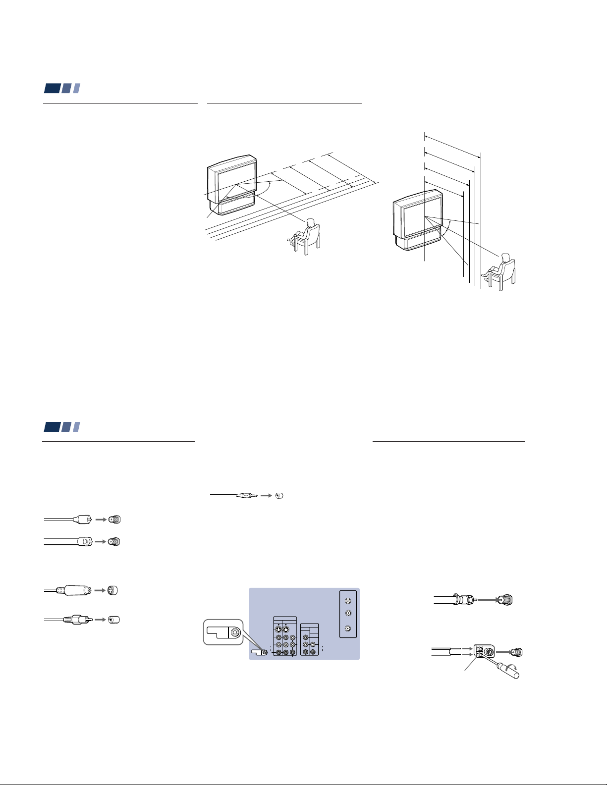
Installing the Projection TV
Recommended viewing area
(Horizontal)
60°
60°
min. 1.8m (approx. 6 ft.)
min. 1.5m (approx. 5 ft.)
43"
60°
min. 2.4m (approx. 8 ft.)
min. 2.1m (approx. 7 ft.)
53"
46", 48"
Recommended viewing area
(Vertical)
min. 2.4m (approx. 8ft.)
61"
min. 2.1m (approx. 7ft.)
53"
61"
min. 1.8m (approx. 6ft.)
46", 48"
min. 1.5m (approx. 5ft.)
43"
20°
20°
3
Installing and Connecting the Projection TV (continued)
Connector Types
You may find it necessary to use some of the
following connector types during set up.
Coaxial cable
Standard TV cable and antenna cable
Plug Type
Push into connection.
Screw-on Type
Screw into connection.
S Video cable
High quality video cable for enhanced
picture quality
Audio/Video cable
Video - Yellow
Audio (Left) - White
Audio (Right) - Red
Some DVD Players and DTV Receivers are
equipped with the following three video
connectors.
Y - Green
B (CB, Cb or B–Y) - Blue
P
P
R (CR, Cr or R–Y) - Red
4
Align guides and
push into connection.
Push into connection.
CONTROL S cable
Sony cable for CONTROL S connection. This
feature is exclusive to Sony products and
allow greater control of all Sony equipment.
Push into connection.
About the CONTROL S OUT jack
To control other Sony equipment with the
projection TV’s remote control, connect the
CONTROL S IN jack of the equipment to the
CONTROL S OUT jack on the projection TV
with the CONTROL S cable.
(Rear of projection TV)
AUX
TO
CONVERTER
IN
CONTROL S
OUT
CONTROL S
VIDEO 1 VIDEO 3
S VIDEO
VIDEO
L
(MONO)
AUDIO
R
OUT
COMPONENT
MONITOR AUDIO
Y
P
B
PR
OUT
(VAR/FIX)
VHF/UHF
VIDEO
L
(MONO)
AUDIO
R
Making Connections
Connecting directly to a cable or
an antenna
The connection you choose will depend on
the cable found in your home. Newer homes
will be equipped with standard coaxial cable
(see A); older homes will probably have 300ohm twin lead cable (see
homes may contain both (see
Use 75-ohm coaxial cable for improved
picture quality (see
A
• VHF only
or
• VHF/UHF
or
• Cable
B
• VHF only
or
• UHF only
or
• VHF/UHF
Antenna connector
B
); still other
A
).
75-ohm
coaxial cable
300-ohm twin
lead cable
C
).
(Rear of
projection TV)
VHF/UHF
(Rear of
projection TV)
VHF/UHF
– 10 –
C
75-ohm coaxial cable
• VHF
(Rear of
projection TV)
VHF/UHF
and
EAC-66 U/V mixer
• UHF
(not supplied)
300-ohm twin lead cable
Cable or antenna
This is the simplest connection. Connection is
made directly from the cable or antenna to
the projection TV.
(Rear of projection TV)
Coaxial cable
VHF/UHF
Cable and antenna
You may find it convenient to use the
following set up if your cable provider does
not feature local channels that you are able to
receive using an antenna.
(Rear of projection TV)
Coaxial cable
(No connection “TO
CONVERTER” in this case)
Antenna cable
AUX
TO CONVERTER
VHF/UHF
Select Cable or ANT mode by pressing ANT
on the remote control.
Connecting a cable box
Some pay cable TV systems use scrambled or
encoded signals that require a cable box* to
view all channels.
Also, set “Cable” to “On” in the Channel Set
Up menu (page 27).
(Rear of projection TV)
Coaxial cable
IN
*Cable box
OUT
VHF/UHF
Cable box and cable
Some pay cable TV systems use scrambled or
encoded signals requiring a cable box* only for
certain channels (e.g. HBO, SHOWTIME, etc.)
*Cable box
Scrambled
channels
75-ohm coaxial cable
(not supplied)
CATV cable
(unscrambled channels)
For this set up, you can switch between
scrambled channels (through your cable
box), and normal (CATV) channels by
pressing ANT on your remote control.
Notes:
• You may be able to program your Sony
remote control to operate your cable box.
(see “Operating a Cable Box or Satellite
Receiver (SAT)” on page 45)
• During PIP or Favorite Channel viewing,
the AUX input can only be viewed in the
main picture.
(Rear of projection TV)
AUX
TO CONVERTER
(Signal)
VHF/UHF
5
Installing and Connecting the Projection TV (continued)
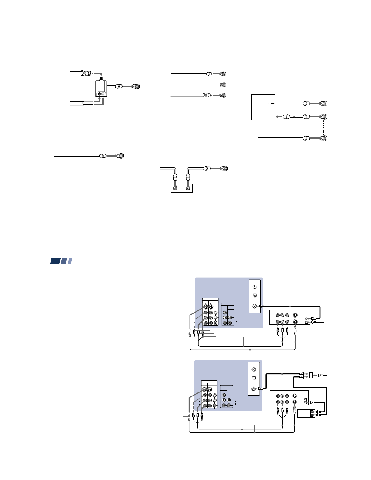
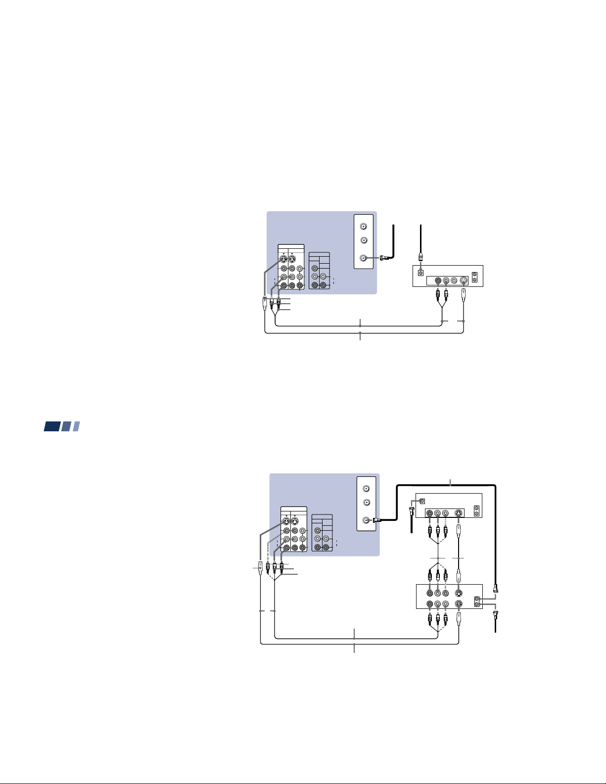
Connecting a cable TV system/
antenna to a VCR
1 Attach the coaxial cable from the
incoming cable connection or antenna to
VHF/UHF IN on the VCR.
2 Using a coaxial cable, connect VHF/UHF
OUT on the VCR to VHF/UHF on the
projection TV.
3 Using AUDIO and S VIDEO* cables,
connect AUDIO and S VIDEO OUT on the
VCR to AUDIO and S VIDEO IN on the
projection TV (White-AUDIO Left, RedAUDIO Right**).
Connecting a VCR and projection
TV to a cable box
1 Connect the single (input) jack of the
splitter to the incoming cable connection,
and connect the other two (output) jacks
(using the coaxial cable) to IN on the cable
box and VHF/UHF on the projection TV.
2 Using a coaxial cable, connect OUT on the
cable box to VHF/UHF IN on the VCR.
3 Using AUDIO and S VIDEO* cables,
connect AUDIO and S VIDEO OUT on the
VCR to AUDIO and S VIDEO IN on the
projection TV (White-AUDIO Left, RedAUDIO Right**).
6
S VIDEO
S VIDEO
Disconnect all power sources before making any connections.
(Rear of projection TV)
AUX
TO
IN
VIDEO 1 VIDEO 3
S VIDEO
VIDEO
L
(MONO)
AUDIO
R
COMPONENT
VIDEO
AUDIO-L
AUDIO-R
MONITOR AUDIO
Y
P
B
PR
(Rear of projection TV)
IN
VIDEO 1 VIDEO 3
S VIDEO
VIDEO
L
(MONO)
AUDIO
R
COMPONENT
VIDEO
AUDIO-L
AUDIO-R
MONITOR AUDIO
Y
B
P
PR
OUT
(VAR/FIX)
VIDEO
L
(MONO)
AUDIO
R
VMC-810S/820S
(not supplied)
OUT
(VAR/FIX)
VIDEO
L
(MONO)
AUDIO
R
VMC-810S/820S
(not supplied)
CONVERTER
VHF/UHF
YC-15V/30V
(not supplied)
AUX
TO
CONVERTER
VHF/UHF
YC-15V/30V
(not supplied)
Coaxial cable
2
AUDIO R AUDIO L VIDEO
LINE
IN
LINE
OUT
Coaxial cable
AUDIO R AUDIO L VIDEO
LINE
IN
LINE
OUT
S VIDEO
VCR
VHF/UHF
OUT
IN
3
1
Splitter (not supplied)
S VIDEO
VCR
VHF/UHF
OUT
IN
OUT
IN
Cable box
3
2
1
Cable/
Antenna
Cable/
Antenna
– 11 –
Note:
• To view scrambled channels through the
cable box, select the video input which the
cable box is connected to by pressing TV/
VIDEO.
* If your VCR is not equipped with S VIDEO, use a
VIDEO cable (yellow) instead of the S VIDEO
cable.
** If you are connecting a monaural VCR, connect
only the single audio output to the left (MONO)
input on the projection TV.
Connecting a satellite receiver
(SAT)
1 Connect the cable from the satellite
antenna to the satellite receiver.
2 Attach the coaxial cable from the incoming
cable connection or antenna to VHF/UHF
on the projection TV.
3 Using AUDIO and S VIDEO cables,
connect AUDIO and S VIDEO OUT on the
satellite receiver to AUDIO and S VIDEO
IN on the projection TV (White-AUDIO
Left, Red-AUDIO Right).
Note:
• To view input from the satellite receiver,
select the video input which the satellite
receiver is connected to by pressing TV/
VIDEO on the remote control.
Disconnect all power sources before making any connections.
(Rear of projection TV)
IN
VIDEO 1 VIDEO 3
S VIDEO
VIDEO
L
(MONO)
AUDIO
R
MONITOR AUDIO
Y
P
B
PR
COMPONENT
S VIDEO
AUDIO-L
AUDIO-R
CONVERTER
OUT
(VAR/FIX)
VHF/UHF
VIDEO
L
(MONO)
AUDIO
R
RK-74A (not supplied)
YC-15V/30V (not supplied)
Cable/
Antenna
AUX
TO
Satellite antenna
cable
12
SATELLITE IN
AUDIO R AUDIO L VIDEO
LINE OUT
S VIDEO
SAT
VHF/UHF
IN
OUT
3
7
Installing and Connecting the Projection TV (continued)
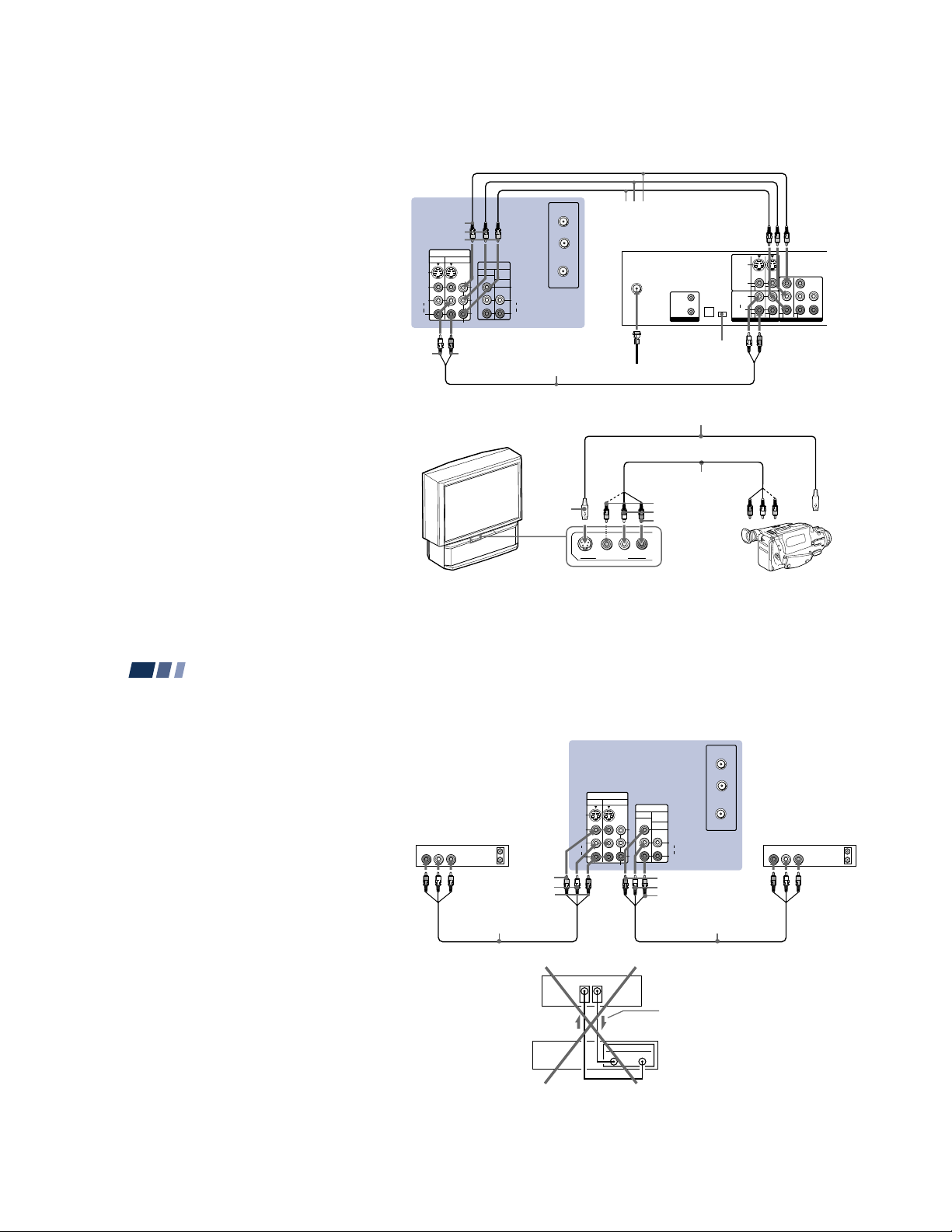
Connecting a satellite receiver
(SAT) and a VCR
1 Connect the cable from the satellite
antenna to the satellite receiver.
2 Attach the coaxial cable from the
incoming cable connection or antenna to
VHF/UHF IN on the VCR.
3 Using a coaxial cable, connect VHF/UHF
OUT on the VCR to VHF/UHF on the
projection TV.
4 Using AUDIO and S VIDEO* cables,
connect AUDIO and S VIDEO OUT on the
satellite receiver to AUDIO and S VIDEO
IN on the VCR.
5 Using AUDIO and S VIDEO* cables,
connect AUDIO and S VIDEO OUT on the
VCR to AUDIO and S VIDEO IN on the
projection TV (White-AUDIO Left, RedAUDIO Right).
If your VCR is not equipped with S VIDEO, use a
*
VIDEO cable (yellow) instead of the S VIDEO
cable.
Note:
• To view input from the satellite receiver or
VCR, select the video input which your
satellite receiver or VCR is connected to
by pressing TV/VIDEO on the remote
control.
8
S VIDEO
(Rear of projection TV)
IN
VIDEO 1 VIDEO 3
S VIDEO
VIDEO
L
(MONO)
AUDIO
R
VIDEO
5
Disconnect all power sources before making any connections.
SATELLITE IN
AUDIO R AUDIO L VIDEO
LINE
OUT
AUDIO R AUDIO L VIDEO
LINE
IN
LINE
OUT
Coaxial cable
SAT
VHF/UHF
S VIDEO
OUT
IN
YC-15V/
30V
4
(not
supplied)
S VIDEO
VHF/UHF
OUT
IN
MONITOR AUDIO
Y
B
P
PR
COMPONENT
AUDIO-L
AUDIO-R
3
AUX
TO
CONVERTER
OUT
(VAR/FIX)
VHF/UHF
VIDEO
L
(MONO)
AUDIO
R
1
Satellite
antenna
cable
VMC-810S/
820S (not
supplied)
VCR
2
VMC-810S/820S (not supplied)
Cable/
Antenna
YC-15V/30V (not supplied)
– 12 –
Connecting a DTV (digital television) receiver
Before connecting, be sure to read the
Operating Instructions of the DTV receiver.
1 Attach the coaxial cable from the roof
antenna to VHF/UHF on the DTV
receiver.
2 Using three yellow VIDEO cables,
connect Y, PB and PR of VIDEO OUT on
the DTV receiver to Y, PB and PR of
VIDEO 3 IN on the projection TV.
3 Using an AUDIO cable, connect AUDIO
OUT on the DTV receiver to AUDIO of
VIDEO 3 IN on the projection TV (WhiteAUDIO Left, Red-AUDIO Right).
4 Set the DOWN CONVERTER ON/OFF
switch on the DTV receiver to ON.
S VIDEO
AUDIO-L
VIDEO
L
(MONO)
AUDIO
R
VIDEO 1 VIDEO 3
Connecting a camcorder
Use this connection to view a picture directly
from your camcorder.
1 Using AUDIO and S VIDEO* cables,
connect AUDIO and S VIDEO OUT on
the camcorder to AUDIO and S VIDEO
IN inside the drop-down panel on the
front of the projection TV (White-AUDIO
Left, Red-AUDIO Right**).
2 Press VIDEO 2 to select the video inputs
from a camcorder.
* If your camcorder is not equipped with S
VIDEO, use a VIDEO cable (yellow) instead of
the S VIDEO cable.
** If you are connecting a monaural camcorder,
connect only the single audio output to the left
(MONO) input on the projection TV.
Y
P
B
P R
IN
OUT
MONITOR AUDIO
(VAR/FIX)
Y
B
P
PR
COMPONENT
(Rear of projection TV)
AUDIO-R
RK-74A (not supplied)
Disconnect all power sources before making any connections.
2
VMC-10HG (not supplied)
AUX
TO
VIDEO
L
(MONO)
AUDIO
R
CONVERTER
VHF/UHF
S VIDEO
(Front of projection TV)
S VIDEO
DTV receiver
VHF/UHF
(DTV)
1
Roof antenna
YC-15V/30V (not supplied)
VMC-810S/820S
(not supplied)
VIDEO
AUDIO-L
AUDIO-R
AUDIO
R
L
VIDEO
(MONO)
VIDEO 2 INPUT
IN
OUT
CONTROL S
DOLBY DIGITAL
AUDIO OUT
(OPTICAL)
DOWN
CONVERTER
ON/OFF
4
S VIDEO
(MONO)
VIDEO
L
R
AUDIO OUT
1
2Y
1 2 3 4
3
Audio/
video
outputs
Camcorder
B
P
P
R
VIDEO OUT
R
GBHD
VD
S VIDEO
OUT
9
Installing and Connecting the Projection TV (continued)
Connecting two VCRs for tape
editing
By connecting a second VCR to MONITOR
OUT, you can record a program being played
by the primary VCR to the second VCR or
perform tape editing and dubbing.
1 Connect the VCR intended for playback
using the connection instructions on page
6 of this manual.
2 Using an AUDIO/VIDEO cable, connect
AUDIO and VIDEO IN on the VCR
intended for recording to AUDIO and
VIDEO OUT of MONITOR OUT on the
projection TV.
Notes:
• Do not change the input signal while
editing through MONITOR OUT.
• When connecting a single VCR to the
projection TV: if VCR LINE OUT is
connected to VIDEO IN on the projection
TV, do not connect MONITOR OUT on
the projection TV to the VCR LINE
INPUT (see right). Doing so will cause
program interference and other viewing
problems.
10
VCR (for playback)
AUDIO R AUDIO L VIDEO
1
OUT
LINE
IN
OUT
VMC-810S/820S
(not supplied)
Disconnect all power sources before making any connections.
(Rear of projection TV)
AUX
TO
CONVERTER
IN
S VIDEO
VIDEO
AUDIO-L
AUDIO-R
(Rear of projectionTV)
VIDEO IN
VCR
VIDEO
L
(MONO)
AUDIO
R
VIDEO 1 VIDEO 3
MONITOR
OUT
IN
COMPONENT
LINE
OUT
MONITOR AUDIO
(VAR/FIX)
Y
B
P
PR
VIDEO
AUDIO-L
AUDIO-R
Indicates direction
of signal
OUT
VHF/UHF
VIDEO
L
(MONO)
AUDIO
R
VMC-810S/820S
(not supplied)
VCR (for recording)
AUDIO R AUDIO L VIDEO
LINE
IN
2
OUT
IN
– 13 –
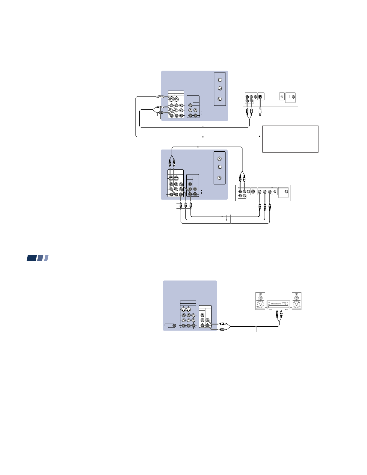
Connecting a DVD Player (Upper
illustration)
Using an AUDIO and S VIDEO cables,
connect AUDIO and S VIDEO IN on the
projection TV to AUDIO and S VIDEO OUT
on the DVD Player (White-AUDIO Left, RedAUDIO Right).
Connecting a DVD Player with
component video output
connectors (Lower illustration)
1 Using an AUDIO cable, connect AUDIO of
LINE OUT on the DVD Player to AUDIO of
VIDEO 3 IN on the projection TV (WhiteAUDIO Left, Red-AUDIO Right).
2 Using three yellow VIDEO cables, connect
Y, P
B, and PR of COMPONENT VIDEO
OUT on the DVD Player to Y, P
VIDEO 3 IN on the projection TV.
Notes:
• Since the high quality pictures on a DVD
disc contain a lot of information, picture
noise may appear. In this case, adjust “Noise
Reduction” in the Video menu. (see “Noise
Reduction” on page 22)
• Some DVD Player terminals may be labeled
differently. If so, connect as follows:
Connect Y (green) to Y.
Connect P
Connect P
B (blue) to CB, Cb or B-Y.
R (red) to CR, Cr or R-Y.
B, and PR of
S VIDEO
AUDIO-R
AUDIO-L
(Rear of
projection
TV)
Disconnect all power sources before making any connections.
(Rear of projection TV)
IN
VIDEO 1 VIDEO 3
S VIDEO
S VIDEO
VIDEO
L
(MONO)
AUDIO
R
VIDEO
L
(MONO)
AUDIO
R
Y
P
B
PR
COMPONENT
RK-74A (not supplied)
YC-15V/30V (not supplied)
RK-74A (not supplied)
AUDIO-L
AUDIO-R
IN
VIDEO 1 VIDEO 3
Y
B
P
PR
COMPONENT
PR
PB
Y
OUT
MONITOR AUDIO
(VAR/FIX)
OUT
MONITOR AUDIO
(VAR/FIX)
VIDEO
L
(MONO)
AUDIO
R
VIDEO
L
(MONO)
AUDIO
R
AUX
TO
CONVERTER
VHF/UHF
AUX
TO
CONVERTER
VHF/UHF
VMC-10HG
(not supplied)
LINE OUT
R–AUDIO 1–L VIDEO
LINE OUT
R–AUDIO 1–L VIDEO
S VIDEO OUT
DVD
S VIDEO OUT
S-LINK
DIGITAL OUT
OPTICAL COAXIAL
Audio/S video
outputs
Connect the DVD Player
directly to the projection TV.
Connecting the DVD Player
through other video
equipment will cause
unwanted picture noise.
DVD
S-LINK
COMPONENT VIDEO OUT
DIGITAL OUT
OPTICAL COAXIAL
R-YY B-Y
11
Installing and Connecting the Projection TV (continued)
Connecting an audio system
For more dynamic sound, connect an audio
system to the projection TV.
1 Using an AUDIO cable, connect AUDIO
(VAR/FIX) OUT on the projection TV to
one of the unused Line inputs (e.g. Tape2, AUX1, etc.) on the stereo.
2 Set the stereo to the chosen Line input
and use the Audio menu to set the audio
output and switch the TV’s speakers off.
(see “Audio Out” and “Speaker” on page
24)
Note:
• You can adjust VOLUME, “Bass,”
“Treble,” “Balance,” “MTS/SAP” and
“Effect” with the supplied remote control.
The control items except VOLUME can be
adjusted only when “Audio Out” is set to
“Variable” in the Audio menu. (see
“Audio Out” on page 24)
12
Disconnect all power sources before making any connections.
(Rear of projection TV)
IN
VIDEO 1 VIDEO 3
S VIDEO
CONTROL S
VIDEO
L
(MONO)
AUDIO
R
OUT
COMPONENT
Y
P
B
PR
OUT
MONITOR AUDIO
(VAR/FIX)
VIDEO
L
(MONO)
AUDIO
R
AUDIO-L
(white)
AUDIO-R
(red)
Stereo amplifier
RK-74A
(not supplied)
HRD
Line inputs
– 14 –
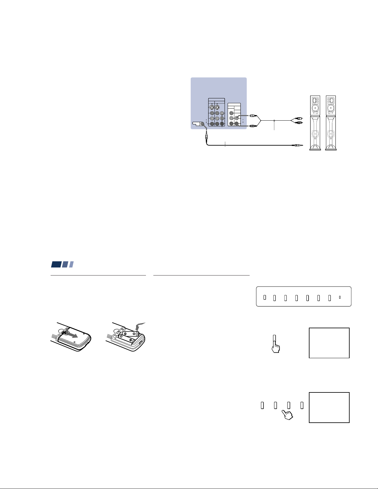
Connecting a Sony SAVA series
VOLUME
–+
CHANNEL
–+
TV/VIDEO
FLASH FOCUS
VOLUME
POWER
TIMER/STAND BY
–+
CHANNEL
–+
speaker system
Use this connection to control the speaker’s
Dolby* Pro Logic surround system and
super woofer mode with the remote control.
(see “SAVA SP Control” on page 24)
1 Using the AUDIO cable supplied with the
speaker to AUDIO (VAR/FIX) OUT on
the projection TV.
2 Using the CONTROL S cable, connect
CONTROL S IN on the speaker to
CONTROL S OUT on the projection TV.
* Manufactured under license from Dolby
Laboratories Licensing Corporation.
Additionally licensed under Canadian patent
number 1,037,877. “Dolby,” the double-D
symbol a and “Pro Logic” are trademarks of
Dolby Laboratories Licensing Corporation.
(Rear of projection TV)
CONTROL S
OUT
CONTROL S
OUT
Disconnect all power sources before making any connections.
SAVA series
speaker system
IN
VIDEO 1 VIDEO 3
S VIDEO
VIDEO
L
(MONO)
AUDIO
R
RK-G34, etc. (not supplied)
COMPONENT
Y
B
P
PR
OUT
MONITOR AUDIO
(VAR/FIX)
VIDEO
L
(MONO)
AUDIO
R
AUDIO-R (red)
AUDIO-L
(white)
Audio cord supplied
with the speakers
1 IN L
1
1 IN R
2
CONTROL S IN
13
Basic Set Up
Using the Remote Control
Inserting the batteries
Insert two size AA (R6) batteries (supplied)
by matching the + and – on the batteries to
the diagram inside the remote control’s
battery compartment.
Notes:
• Remove the batteries to avoid damage
from possible battery leakage whenever
you anticipate that the remote control
will not be used for an extended period.
• Handle the remote control with care.
Avoid dropping it, getting it wet, or
placing it in direct sunlight, near a heater
or where the humidity is high.
• Your remote control can be programmed to
operate most video equipment.
(see “Operating Video Equipment” on
page 43)
14
Setting Up the Projection TV
Automatically
The AUTO SET UP feature will allow you to
set the on-screen language and set all
receivable channels.
The AUTO SET UP feature does not apply for
installations that use a cable box for all channel
selection.
You can also set up the projection TV manually.
(see “Using the Channel Set Up menu” on pages
26 and 27)
Notes:
• Before you perform AUTO SET UP again,
make sure that the input from ANT (not
AUX) is selected by pressing ANT until
“AUX” does not appear next to the
channel number.
• Perform this function during the day, with
the antenna and/or cable properly
connected, to ensure that all available
channels will be broadcasting and
receivable.
• When you perform AUTO SET UP, all the
settings in the Video, and Audio menus
are reset to the factory settings.
Using the buttons on the front panel of the
projection TV:
1 Press POWER to turn on the projection
TV.
The AUTO SET UP screen appears.
POWER
English :
Español :
Français :
Auto Set Up :
First please connect
the antenna.
Press [ SET UP ] to exit.
[CH+]
[CH–]
[VOL+]
[VOL–]
2 Press CHANNEL + to select English,
CHANNEL – to select Español or
VOLUME + to select Français.
The screen will change to reflect your
choice.
English :
Español :
Français :
Auto Set Up :
Primero conecte la
antena.
Oprima [ SET UP ] para
salir.
[CH+]
[CH–]
[VOL+]
[VOL–]
– 15 –
3 Press VOLUME – to continue.
FLASH FOCUS
VOLUME
–+
Continue to
Auto Program ?
Yes :
No :
[CH+]
[CH–]
To perform AUTO SET UP again
FLASH FOCUS
TV/VIDEO
MENUSET UP
4 Press CHANNEL + to preset channels
automatically.
CHANNEL
–+
Auto Program
“Auto Program” appears and the
projection TV starts scanning and
presetting channels automatically. While
scanning, the received channel will be
displayed on the sub screen. When all the
receivable channels are stored, the lowest
numbered channel is displayed.
Using Your New Projection TV
Using Your New Projection TV (continued)
Watching the TV
Many TV features can be accessed directly
through the remote control. The following
chart will explain the function of some
buttons found on your remote control.
Press SET UP inside the drop-down panel on
the projection TV and perform steps 2-4
above.
Press SET UP again to exit.
Adjusting the Convergence
Automatically (FLASH FOCUS)
The projection tube image appears on the
screen in three layers (red, green and blue). If
they do not converge, the color is poor and
the picture blurs.
Before you use your projection TV, be sure to
adjust the convergence.
The FLASH FOCUS feature allows you to
adjust the convergence automatically.
Tips
z
• It is recommended to perform FLASH FOCUS about
30 minutes after the projection TV is first turned on.
• You can also perform FLASH FOCUS using the Set
Up menu on page 31.
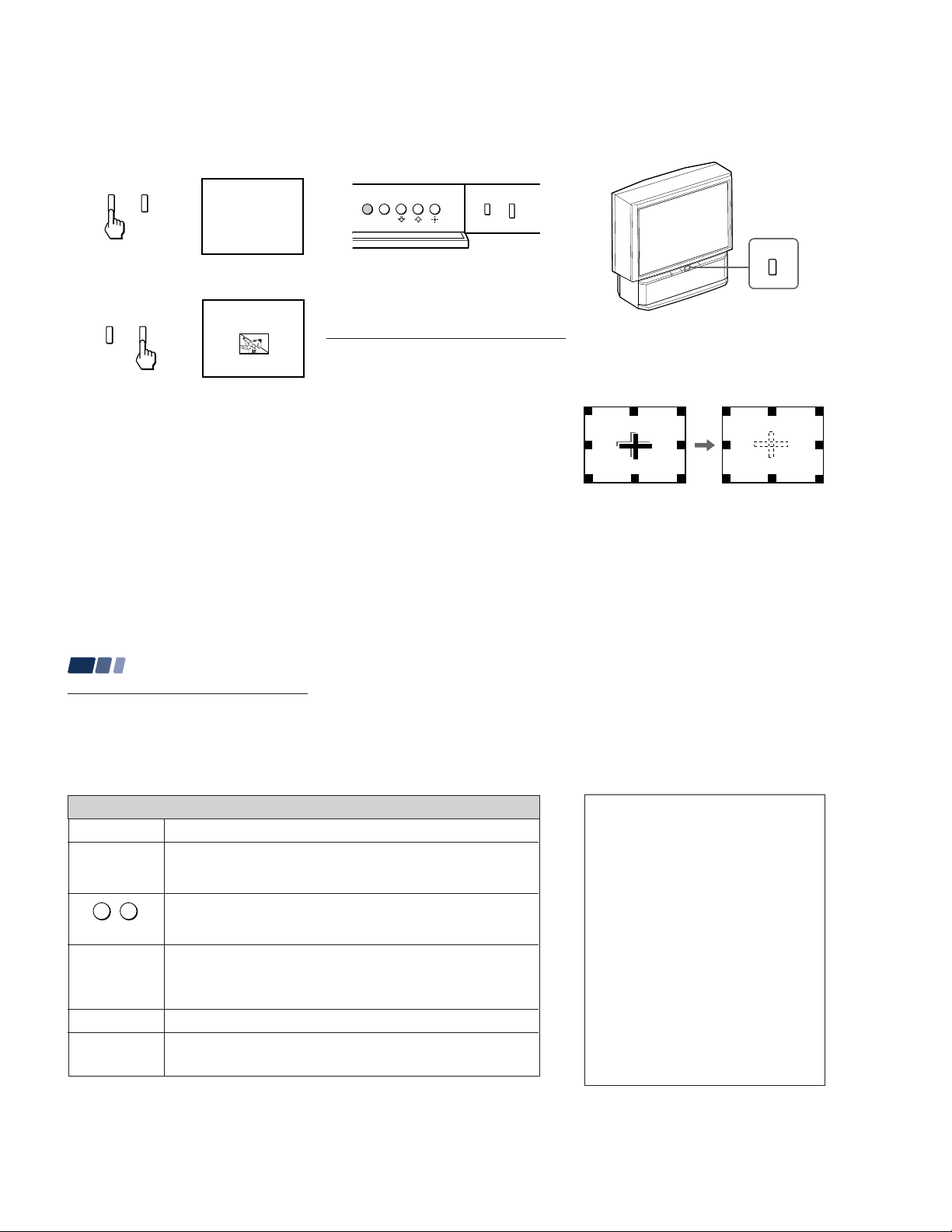
Press FLASH FOCUS.
The cross pattern appears and FLASH
FOCUS begins to work. The adjustment is
completed when the cross pattern becomes
white.
Note:
• FLASH FOCUS is canceled if you
perform any other function while FLASH
FOCUS is working.
15
Using the White Labeled Buttons for Projection TV Operations
TV (FUNCTION)
TV POWER
-
0 9
and ENTER
CH +/–
VOL +/–
MUTING
16
Activates the remote control for use with the projection TV.
Turns the projection TV on and off. If a video input indication (e.g., VIDEO 1,
VIDEO 2) appears on the screen, press TV/VIDEO until a channel number
appears.
Use for direct channel selection. Press 0-9 to select a channel (for example,
to select channel 10, press 1 and 0). The channel will change after 2
seconds, or you can press ENTER for immediate selection.
Press to scan through the channels (+ up or – down).
Speed Surf
1 Press and hold CH + or – to change the channel number rapidly.
2 Release to display the desired channel.
Press to adjust the volume (+ up or – down).
Press to mute the sound. “Muting” will appear on the screen and will dim
three seconds later. To restore sound, press again or press VOL +.
PICTURE MODE
Press PICTURE MODE repeatedly to directly
choose one of five different video modes that
best suits the program you are watching.
Vivid: Select for enhanced picture contrast and
sharpness.
Standard: Select to display a standard
picture for normal viewing environments.
Movie: Select to display a finely detailed
picture for low light environments.
Personal 1, Personal 2: Select to customize
the “Picture Adjustment” of the Video menu
according to your personal preference.
When you select “Movie,” “Personal 1” and
“Personal 2,” you can also perform the “Picture
Adjustment” (such as “Brightness,” “Color,” etc.)
to suit your taste. For details, see “Mode” on
page 22.
– 16 –
Using the White Labeled Buttons for Projection TV Operations
TV/VIDEO
JUMP
FREEZE
(yellow labeled
button)
DISPLAY
Press repeatedly to scroll through available video inputs:
TV, VIDEO 1, VIDEO 2 and VIDEO 3.
If you select “Skip” as a “Video Label” in the Set Up menu, your projection
TV will skip the video input you selected. (see “Video Label” on page 31)
jump
Press to alternate or
back and forth between two channels. The
projection TV will jump between the current channel and the last channel
selected using the 0-9 buttons.
This is useful when you need to copy down information that appears on the
TV’s screen.
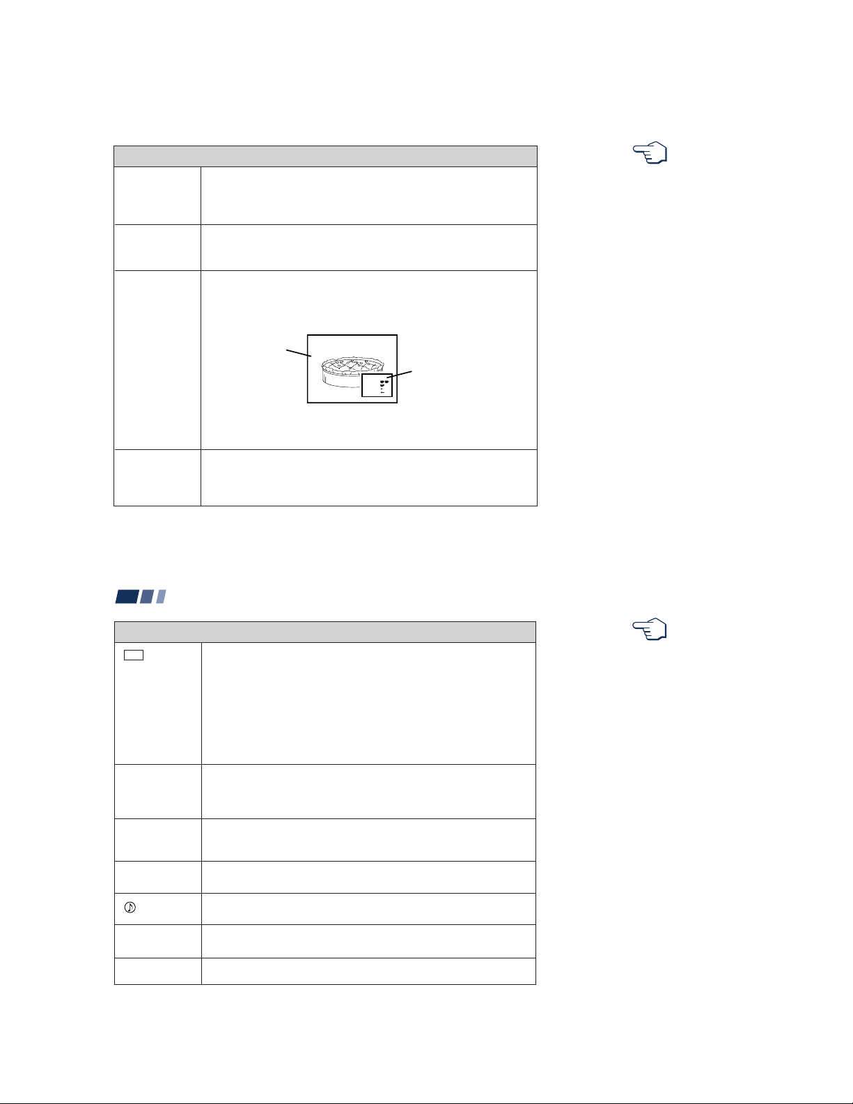
Press to
freeze
the desired picture. The frozen picture is displayed in the
window picture while viewing the normal picture of the current channel in the
main picture.
Reciipe
flour - - - - 2
sugar - - - 1/2
salt - - - - - 1/2
butter - - - 1
6
Frozen picture
Normal motion
picture
To change the location of the window picture, press V, v, B or b.
Press FREEZE again to display the normal picture.
Press to display the channel number, current time, channel caption (if set),
and MTS/SAP mode (if SAP is selected). The SAP indication disappears and
the other indications dim three seconds later.
To turn the display off, press DISPLAY again.
REFER TO THE
ILLUSTRATION OF THE
REMOTE CONTROL ON THE
INSIDE FRONT COVER OF
THIS MANUAL AS YOU
REVIEW THIS CHART
(continued)
17
Using Your New Projection TV (continued)
Using the White Labeled Buttons for Projection TV Operations
CC
SLEEP
ANT
(AUX input)
MTS/SAP
TV/VTR
SYSTEM OFF
18
Press repeatedly to scroll through available displays:
XDS (Extended Data Service)
Displays a network name, program name, program type, program length,
program description, call letters and time of the show if the broadcaster
offers this service.
Caption Vision
Displayed on the screen if the broadcaster offers this service. (see
“Caption Vision” on page 30)
No display
“Off” appears and the display is canceled.
Press repeatedly until the projection TV displays the approximate time in
minutes (30, 60, or 90) that you want the projection TV to remain on before
shutting off automatically.
Cancel by pressing until “Sleep Off” appears.
Press to change between the VHF/UHF input and the AUX input. (for
detailed connection information, see “Cable and antenna” or “Cable box and
cable” on page 5)
Press to scroll through the Multi-channel TV Sound (MTS) options:
Stereo, SAP, Mono and Auto SAP. (see “MTS/SAP” on page 23)
Press to select an audio option:
Simulated, Surround, BBE and Effect Off. (see “Effect” on page 23)
Press when you are finished using a VCR and you want to switch to the TV
input. The VCR power will remain on.
Press to turn off the projection TV and all other Sony equipment.
REFER TO THE
ILLUSTRATION OF THE
REMOTE CONTROL ON THE
INSIDE FRONT COVER OF
THIS MANUAL AS YOU
REVIEW THIS CHART
– 17 –
Watching Two Programs at One Time — PIP
The Picture-in-Picture (PIP) feature allows
you to view two channels simultaneously,
one in the full size “main” picture and one in
a smaller “window” picture.
You can move the window picture to any
location on the screen.
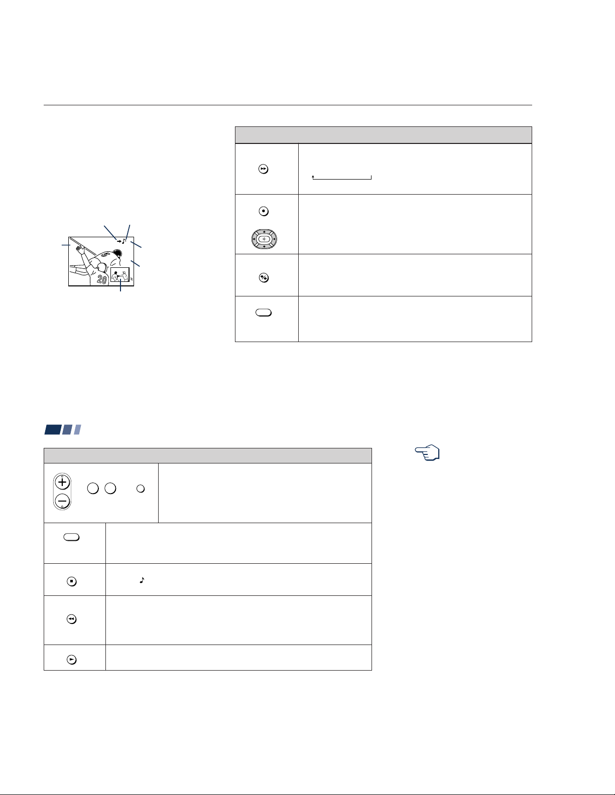
The symbol “b” or “B”
indicates which picture's
TV channel or input
source can be changed.
Main
picture
* It will dim in about 3 seconds.
Tip
z
If you press RESET in PIP mode, the window picture
will move to the bottom right (factory-preset location).
The symbol “≥”
indicates which
picture's sound is being
received.
TV channel or inputsource mode for the
6
main picture* (yellowgreen-colored)
10
TV channel or inputsource mode for the
window picture*
Window
picture
(white-colored)
PIP
POSITION
or
ACTIVE
TV/VIDEO
(white labeled
button)
Using the Yellow Labeled Buttons for PIP Operations
Press to display a window picture.
Each time you press this button, the picture size will change
(1/9 n1/16 nno display).
To close the window picture, press PIP repeatedly until it disappears.
Press POSITION repeatedly to change the location of the window picture
(counterclockwise) around the main picture.
You can also change the location by pressing the V, v, B or b button.
The window picture moves in the direction of the arrow indicated on the
pressed button.
Press to select either the main or window picture in order to change the
TV channel or video source using the white labeled buttons below. The
symbol “b” (or “B”) will appear to indicate which picture’s channel or input
mode can be changed.
Press repeatedly to scroll through the available video inputs for the
picture on which the symbol “b” (or “B”) is displayed. (see “TV/VIDEO” on
page 17)
19
Using Your New Projection TV (continued)
CH
or or
0 9
and ENTER
(white labeled button)
ANT
(white labeled
button)
AUDIO
FREEZE
SWAP
20
Using the Yellow Labeled Buttons for PIP Operations
Press to select the TV channel on which the symbol “b” is
-
JUMP
Press to change between the VHF/UHF input and the AUX input for the picture on
which the symbol “b” (or “B”) is displayed.
Press to alternate sound between the main picture and the window picture. The
symbol “
received.
This is useful when you need to copy down information of the main picture.
Press to freeze the desired scene in the main picture. The frozen picture is displayed
in the window picture while viewing the normal picture in the main picture. The
window picture size is automatically changed to 1/9 if it was 1/16.
Press again to resume normal PIP viewing.
Press to switch the audio and video of the main picture and the window picture.
Each time you press SWAP, the picture and sound of the two will be exchanged.
displayed. (for details, see “Watching the TV” on page 16)
Speed Surf
1 Press and hold CH + or – to change the channel number rapidly.
2 Release to display the desired channel.
” will appear for a few seconds to indicate which picture’s sound is being
REFER TO THE
ILLUSTRATION OF THE
REMOTE CONTROL ON THE
INSIDE FRONT COVER OF
THIS MANUAL AS YOU
REVIEW THIS CHART
Note:
• If one of the pictures received through
PIP is snowy, the entire screen may
become unstable. In this case, erase the
snowy channel. (see “Channel Skip/
Add” on page 27)
– 18 –
Move Select Exit
MENU
Set Up
Parental Control
Caption Vision: CC1
Language: English
Video Label
Flash Focus: No
ch
Adjusting Y our SET UP (menus)
Personal 1
Picture
Hue
Color
Brightness
Sharpness
Move Select Exit
MENU
ch
Learning Menu Selection
Use the MENU button to access a menu and
use the V, v, B, b and
settings. Use the following example to learn
how to modify settings.
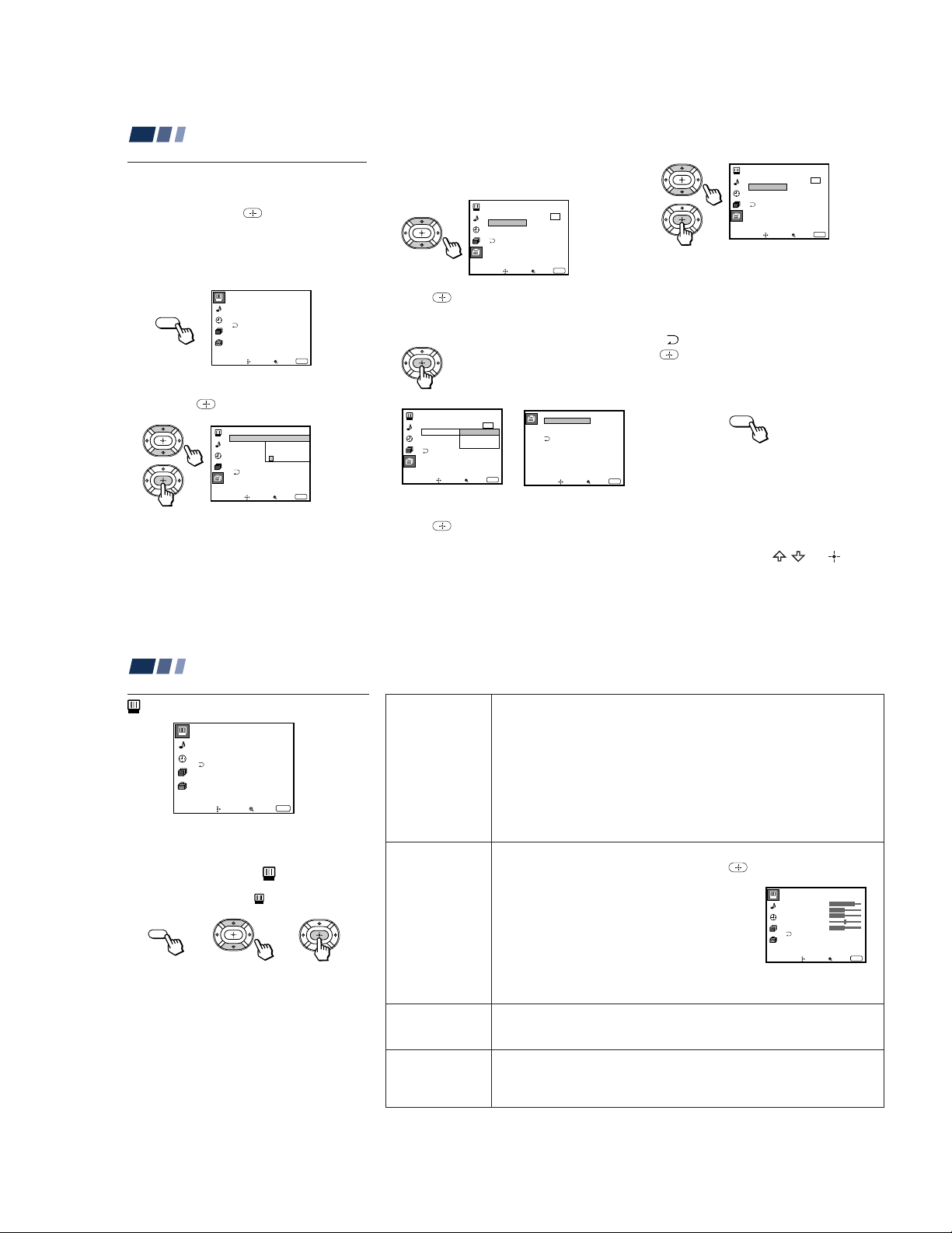
1 Press the MENU button.
The main menu appears.
MENU
2 Press V or v to highlight the desired menu
and press
You may also press b to activate your
selection.
buttons to alter the
Video
Mode: Vivid
Picture Adjustment
Trinitone: High
Noise Reduction: Off
ch
Move Select Exit
to activate it.
Set Up
Parental Control
Caption Vision:
Set New
Language:
Password
_ _ _ _
Video Label
Flash Focus: No
ch
Move Select Exit
MENU
MENU
3 Press V or v to highlight the desired
option.
4 Press .
Options for your selection (Pop-up menu
or Adjusting menu) will be displayed.
Pop-up menu Adjusting menu
Set Up
Parental Control
Caption Vision: CC1
Language: English
Video Label
Flash Focus: No
ch
Move Select
Español
Français
Exit
MENU
Video Label
VIDEO1:
VIDEO2:
VIDEO3:
Move Select Exit
VIDEO1
VIDEO2
VIDEO3
5 Press V or v to make your selection and
press
The previous screen will reappear.
to activate it.
Set Up
Parental Control
Caption Vision: CC1
Language: English
Video Label
Flash Focus: No
ch
Move Select Exit
Some adjustment menus may require
further operations. For details, see each
menu option.
To return to the previous screen (except
for the slider adjustment menus), choose
“ ” at the bottom of the menu and press
or B.
6 Once you have completed all menu
corrections, press MENU to exit the menu
screens.
MENU
To exit from the menus at any
time
MENU
Press MENU.
Tip
z
You can also use the MENU, / and buttons
inside the front drop-down panel of the projection TV
for the menu selection.
MENU
21
Adjusting Y our SET UP (menus) (contin ued)
Using the Video Menu
Video
Mode: Vivid
Picture Adjustment
Trinitone: High
Noise Reduction :Off
ch
Move Select Exit
For detailed information on using the remote
control to modify menu settings, refer to
“Learning Menu Selection” on page 21.
To select the Video menu:
Display / Highlight / Select
MENU
To restore the factory settings
Press RESET on the remote control while the
Video menu is selected. To restore each
“Mode” to the factory setting, press RESET
after selecting the mode to be reset.
22
MENU
Mode
Customized
picture viewing
Picture
Adjustment
Picture adjustment
Trinitone
White intensity
adjustment
Noise Reduction
Noise reduction
You can choose one of five different video modes that best suits the program you
are watching. You can also perform the “Picture Adjustment” (such as
“Brightness,” “Color,” etc.) for “Movie,” “Personal 1” or “Personal 2” to suit your
taste.
Vivid: Select for enhanced picture contrast and sharpness.
Standard: Select to display a standard picture for normal viewing
environments.
Movie: Select to display a finely detailed picture for low light environments.
Personal 1, Personal 2: Select to customize the “Picture Adjustment” of the
Video menu according to your personal preference.
Press PICTURE MODE on the remote control for direct selection of a “Mode
setting.
First select “Movie,” “Personal 1” or “Personal 2” from “Mode,” then highlight the
desired option using the V or v button and press
slider of the selected option.
Picture: Adjust slider right (up) to increase picture
contrast; left (down) to decrease it.
Brightness: Adjust slider right (up) to brighten the
picture; left (down) to darken it.
Color: Adjust slider right (up) to increase color
intensity; left (down) to decrease it.
Hue: Adjust slider right (up) to increase the green
tones; left (down) to increase the red tones.
Sharpness: Adjust slider right (up) to sharpen the
picture; left (down) to soften it.
High: Select to give the white colors a blueish tint.
Medium: Select to give the white colors a neutral tint.
NTSC Standard: Select to give the white colors a reddish tint.
Select On to reduce picture noise.
Select Off to cancel the feature.
“Noise Reduction” can be set separately from the “Mode” settings of the Video
menu.
to display the adjusting
”
– 19 –
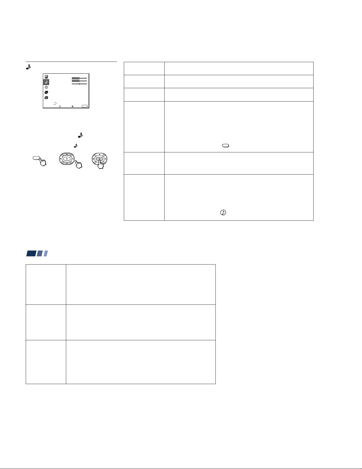
Using the Audio Menu
Audio
Treble
Bass
Balance
MTS/SAP:
Auto Volume:
Effect:
Speaker:
Audio Out:
SAVA SP Control
Move Select Exit
MENU
Stereo
On
On
Variable
Surround
ch
Sliders
}
For detailed information on using the remote
control to modify menu settings, refer to
“Learning Menu Selection” on page 21.
To select the Audio menu:
Display / Highlight / Select
MENU
To restore the factory settings
Press RESET on the remote control while the
Audio menu is selected.
* The BBE is manufactured by Sony Corporation
under license from BBE Sound, Inc. It is covered
by U.S. Patent No. 4,638,258 and No. 4,482,866.
The word “BBE” and the BBE symbol are the
trademarks of BBE Sound, Inc.
Treble
Sound adjustment
Bass
Sound adjustment
Balance
Sound adjustment
MTS/SAP
Enjoy stereo,
bilingual and mono
programs.
Auto Volume
Adjust the sound
level.
Effect
Customizes
surround sound
effects based on the
program’s audio
type.
Adjust slider right (up) to increase high pitched sounds.
Adjust slider left (down) to decrease high pitched sounds.
Adjust slider right (up) to increase low pitched sounds.
Adjust slider left (down) to decrease low pitched sounds.
Adjust slider right (up) to emphasize right speaker volume.
Adjust slider left (down) to emphasize left speaker volume.
When the sound is intermittent due to poor reception conditions, select “Stereo”
or “SAP.”
Stereo: Select for stereo reception when viewing a program broadcast in stereo.
SAP: Select to listen to a bilingual broadcast. (non-SAP programs will be muted
when this feature is selected)
Mono: Select for mono reception. (use to reduce noise during stereo broadcasts)
Auto SAP: Select to listen to SAP when a SAP program is broadcast and return
to stereo reception automatically for non-SAP programs.
Quick MTS access: Press
“MTS/SAP” options as follows: Stereo n SAP n Mono n Auto SAP.
On:
Sound output coming from TV speakers have the volume level equalized for all
channel audio inputs when broadcasts have different sound transmission levels.
Off: Sound output coming from the TV speakers varies according to the received
channel.
“Effect” can only be set when “Speaker” is set to “On” or “Off.”
Simulated: Adds a surround-like effect to mono programs.
Surround: Simulates sound with the atmosphere of a movie theater or a concert
hall for stereo programs.
BBE*: Centers the sound intensity to the front, creating an effect as if you were
seated in front of an orchestra.
Off: Normal stereo or mono reception.
Quick Effect access: Press on the remote control to cycle through the
“Effect” options as follows: Simulated n Surround n BBE n Effect Off.
MTS/SAP
on the remote control to cycle through the
(continued)
23
Speaker
Custom selection
of audio output
source
Audio Out
Easy control of
volume adjustment
SAVA SP Control
Controls Sony
SAVA speaker’s
mode.
24
Adjusting Y our SET UP (menus) (contin ued)
On: Select to listen to the sound from the projection TV speakers alone.
Off: Select to turn off the projection TV speakers and listen to the
projection TV’s sound only through an external audio system’s speakers.
SAVA SP: Select to turn off the projection TV speakers and listen to the projection
TV’s sound only through the Sony SAVA series speaker system. You can
adjust volume, muting, “Surround Mode,” and “Super Woofer Mode” with the
projection TV’s remote control. (see “SAVA SP Control” below)
“Audio Out” can only be set when “Speaker” is set to “Off.”
Fixed: Sound output is held at a fixed level through the audio system.
Use the AV receiver’s remote control to adjust the volume.
Variable: Sound output varies according to the TV settings.
Useful when you want to use your remote control to control the output of a
separate audio system.
“SAVA SP Control” can only be set when Sony SAVA speaker system is
connected to the AUDIO (VAR/FIX) OUT connectors and “Speaker” is set to
“SAVA SP.” (see “Speaker” above)
You can also adjust the SAVA speaker’s volume using VOL +/– of the projection
TV’s remote control.
Surround Mode: Select to activate the SAVA Speaker’s surround mode.
Super Woofer Mode: Select to activate the SAVA Speaker’s super woofer mode.
– 20 –
Channel Caption
Caption: – ––––
Channel: –––
Move Select Exit
MENU
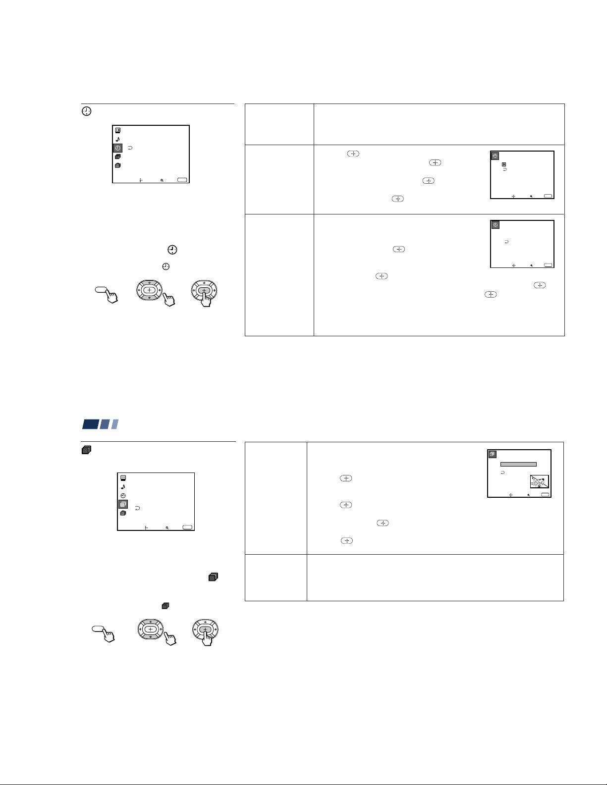
Using the Timer Menu
Timer
Daylight Savings: Yes
Current Time
On / Off Timer
ch
----- : - AM-
Move Select Exit
After setting the clock you can use the timer
to turn the projection TV on and off.
For detailed information on using the remote
control to modify menu settings, refer to
“Learning Menu Selection” on page 21.
To select the Timer menu:
Display / Highlight / Select
MENU
Tip
z
Set daylight saving time before setting the clock. Any
loss of power will cause these settings to be erased.
MENU
Daylight Savings
Automatically
adjusts the time.
Current Time
Necessary for the
Timer.
On/Off Timer
Wake up or
scheduled viewing.
Spring: Select Yes to compensate for Daylight Saving Time.
The current time automatically moves ahead one hour.
Fall: Select No at the end of Daylight Saving Time.
The current time moves back one hour.
1 Press
(Sun-Sat) is displayed, and press
, then press V or v until the current day
.
2 Press V or v until the current hour (1-12) and
AM/PM is displayed, and press
.
3 Press V or v until the current minute (00-59) is
displayed, and press
.
Current Time
––: –AM–
–––
Move Select Exit
MENU
The clock has now started. Press MENU to exit.
1 Press V or v until the desired day or range of days
(Every Sun-Sat, Every Mon-Fri, Sunday, Monday, ...
Saturday, Every Sunday, ... Every Saturday) is
displayed, and press
.
2 Press V or v until the time (hours and minutes) that
you want the projection TV to remain on is displayed,
and then press
.
3 Press V or v to set the time duration (maximum of 6 hours) and press
4 Press V or v to select the desired channel and press
On/Off Timer
––––––
––: ––AM–hch
Sun
12:00AM
Move Select Exit
.
–––
MENU
.
The timer is now set. The TIMER/STAND BY indicator on your projection TV
will be lit.
Press MENU to exit. To cancel your timer setting, press RESET while in the On/
Off Timer window. Performing Auto Program will erase all Timer settings.
25
Adjusting Y our SET UP (menus) (contin ued)
ch
Using the Channel Set Up
Menu
Channel Set Up
Channel Caption
Favorite Channel :Auto
Channel Skip/Add
Auto Program
Cable: On
ch
Move Select Exit
For detailed information on using the remote
control to modify menu settings, refer to
“Learning Menu Selection” on page 21.
To select the Channel Set Up
menu:
Display / Highlight ch / Select
MENU
26
MENU
ch
Channel
Caption
Easy recognition
of the channel
you are watching
Favorite
Channel
User’s favorite
channels
You can add a caption for up to 32 channels of VHF/
UHF input.
With the Channel Caption window open:
1 Press
and then press V or v to select the desired
channel. You can view the channel that is selected
with the Channel Caption menu in the sub screen.
2 Press
.
3 Press V or v to display the first letter or number of the
caption and press
to select it.
Repeat until up to five digits are selected.
4 Press
.
To erase a caption, press RESET.
The Favorite Channel feature enables easy access to the eight channels that you
preset (or the last channel that you were watching).
(for details on how to set up this feature, see “Setting and Selecting Favorite
Channel” on page 28)
– 21 –
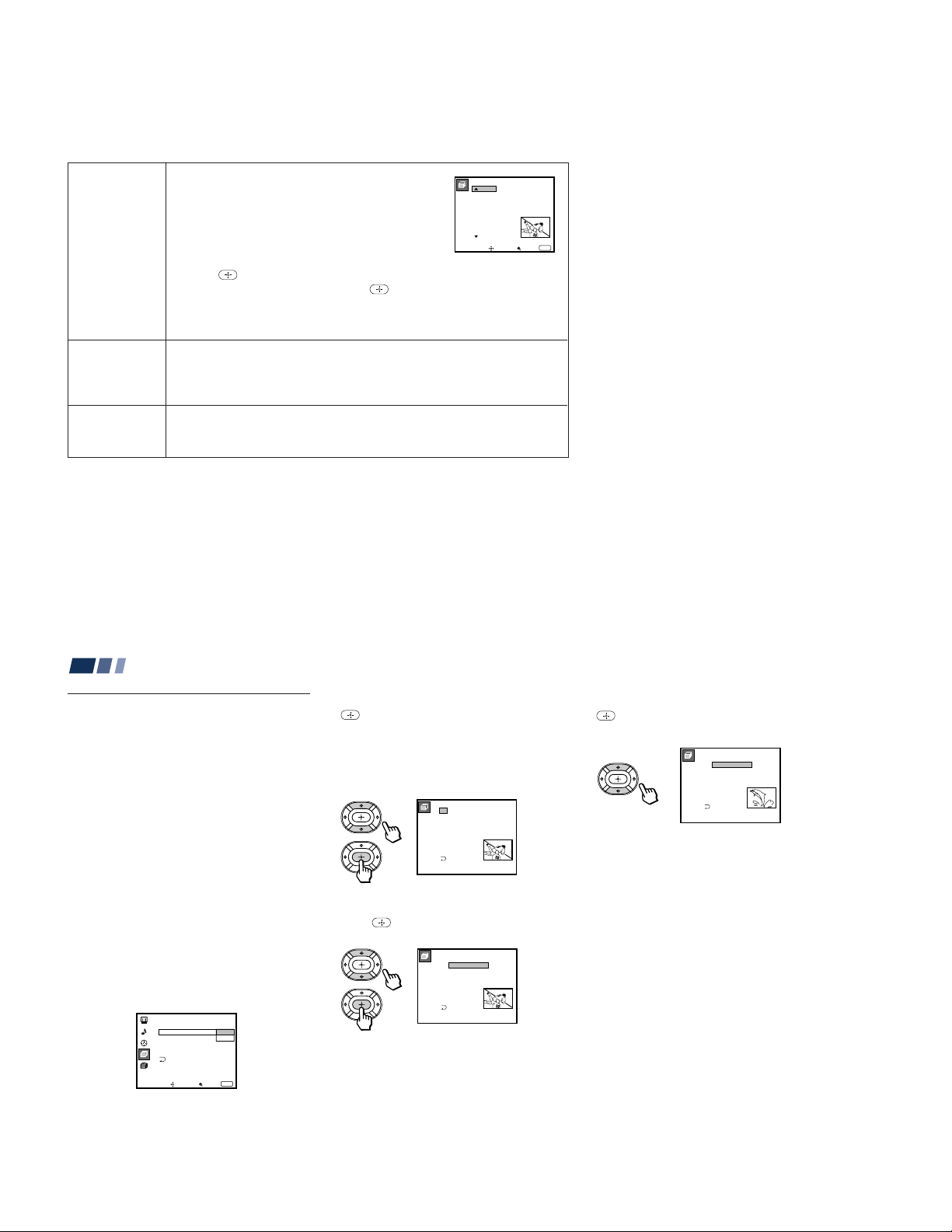
Channel
Channel Skip/Add
Select a channel
2:
3:
4:
5:
6:
7:
8:
1:
Move Select Exit
MENU
9:
Skip
Skip
Add
Add
Add
Add
Add
Add
Add
ch
Skip/Add
Skips unnecessary
channels.
Auto Program
Automatic
channel presetting
Cable
Cable system
setting
After AUTO SET UP, you can erase unnecessary
channels from the channel preset memory.
With the Channel Skip/Add window open:
1 Press V or v to select the desired channel. You can
view the channel that is selected with the Channel
Skip/Add menu in the sub screen. You can also use
CH +/– or 0–9 and ENTER buttons.
2 Press
3 Press V or v to select Skip, and press
.
.
The selected channel will be erased.
If you want to re-enter the skipped channel, follow the steps above and select
Add.
Select Yes to signal the projection TV to automatically program all receivable
channels. When all the receivable channels are stored, the lowest numbered
channel is displayed.
Select No to cancel Auto Program.
Select On if your projection TV is connected to a cable system.
Select Off if your projection TV is connected to an antenna.
27
Adjusting Y our SET UP (menus) (contin ued)
Setting and Selecting
Favorite Channel
The Favorite Channel feature of your
projection TV enables easy access to the eight
channels that you preset (or the last channel
that you were watching).
Your Favorite Channel options can be set
automatically or manually.
The factory setting for “Favorite Channel” is
“Auto.”
When “Favorite Channel” is set to “Auto,”
the last eight channels selected with the 0–9
buttons will be set as Favorite Channel
options. If you want to input your own
selections as Favorite Channel settings, set to
“Manual.”
Setting Favorite Channel manually
1 Select “Favorite Channel” from the
Channel Set Up menu. (see page 26)
Channel Set Up
Channel Caption
28
Favorite Channe: Auto
Channel Skip/Add
Auto Program
Cable: On
ch
Move Select Exit
Manual
MENU
2 Press V or v to select “Manual” and press
.
The Favorite Channel menu will appear.
If you set Channel Caption names (e.g.
CNN, HBO), they will also be displayed.
(see “Channel Caption” on page 26)
Favorite Channel
ch
1
CNN
1.
2
2.
SPTN
10
3.
20
4.
30
5.
40
6.
50
7.
100
8.
Select a position
3 Press V or v to select a position (1–8), and
press
.
Favorite Channel
ch
1
CNN
1.
2
2.
SPTN
10
3.
20
4.
30
5.
40
6.
50
7.
100
8.
Select a channel
4 Press V or v to select a channel and press
.
You have now selected a favorite channel.
Favorite Channel
ch
1
CNN
1.
8
2.
SPTN
10
3.
20
4.
30
5.
40
6.
50
7.
100
8.
Select a channel
5 Use V and v to program other favorite
channels. (Follow steps 3 and 4.)
6 Press MENU when you have finished.
Your favorite channels are now ready for
use.
– 22 –
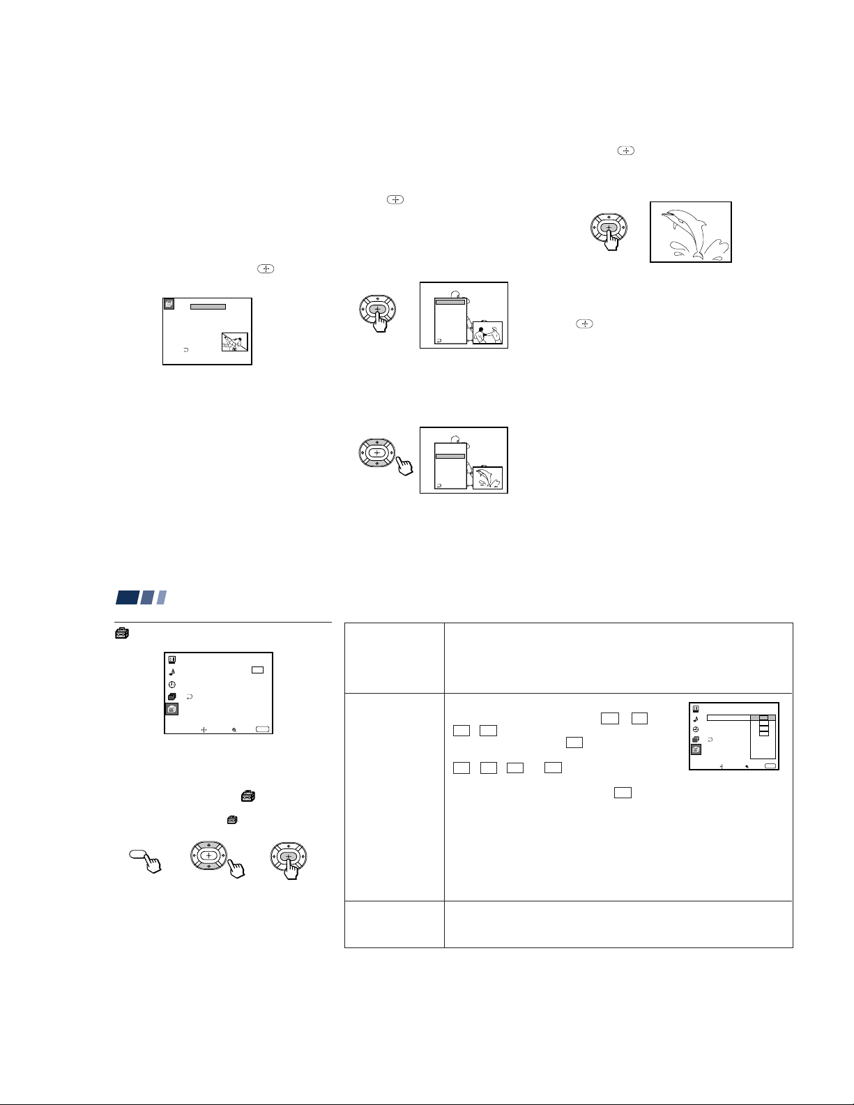
Changing Favorite Channel choices
Favorite Channel
Select a channel
2.
3.
4.
5.
6.
7.
8.
1.
2
10
20
30
40
50
100
6
SPTN
ch
Language:
Move Select Exit
MENU
Set Up
Video Label
Flash Focus: No
Caption Vision: CC 1
CC2
CC3
CC4
Text1
Text2
Text3
Text4
ch
Parental Control
You have the option of returning to the
Favorite Channel screen to adjust any of your
favorite channel choices.
Simply proceed as described in “Setting
Favorite Channel manually” (skip step 2 if
“Manual” is already selected).
When you reach step 3, select the position
you want to change and press
v to select a new channel.
. Press V or
Using Favorite Channel
You can use the Favorite Channel feature to
directly select the channel you want to watch.
1 Press once.
The favorite channel menu and a window
picture will be superimposed over the
current channel. The window picture
displays the channel selected from the
menu.
1 CNN
2
SPTN
10
20
30
40
50
100
Exit
3 Press to select the channel.
The selected channel will be displayed for
normal viewing.
To cancel the favorite channel menu before
selecting a channel, press V or v to select
“Exit” at the bottom of the menu and press
.
Press MENU when you are done.
Adjusting Y our SET UP (menus) (contin ued)
Using the Set Up Menu
Set Up
Parental Control
Caption Vision: CC1
Language: English
Video Label
Flash Focus: No
ch
Move Select Exit
For detailed information on using the remote
control to modify menu settings, refer to
“Learning Menu Selection” on page 21.
To select the Set Up menu:
Display / Highlight / Select
MENU
MENU
2 Press V or v to select the channel that you
wish to view from the menu.
The picture of the selected channel will be
displayed in the window picture.
1 CNN
2
SPTN
10
20
30
40
50
100
Exit
Parental
Control
Blocks programs
unsuitable for
.
children
Caption Vision
Television closed
caption display
Language
Preferred language
Allows you to block TV programs that you feel are unsuitable for your
children.
(see “Using the Parental Control Feature” on page 32 for details)
Some programs are broadcast with Caption Vision.
To display “Caption Vision,” select CC 1, CC 2,
CC 3, CC 4, TEXT1, TEXT2, TEXT3 or TEXT4 from
the menu. Then press the CC button until “Caption
Vision” is displayed.
CC 1, CC 2, CC 3 or CC 4 displays a printed
version of the dialogue or sound effects of a
program. (The mode should be set to CC 1 for most
programs.) TEXT1, TEXT2, TEXT3, or TEXT4
displays network/station information presented using
either half or the whole screen.
Notes:
• Poor reception of TV programs can cause errors in Caption Vision and XDS.
Captions may appear with a white box or other errors instead of the intended
text.
• XDS, Caption Vision, and the status display cannot be used at the same time.
Select from available languages (English, Español or Français) to display all
menus in your language of choice.
29
30
– 23 –
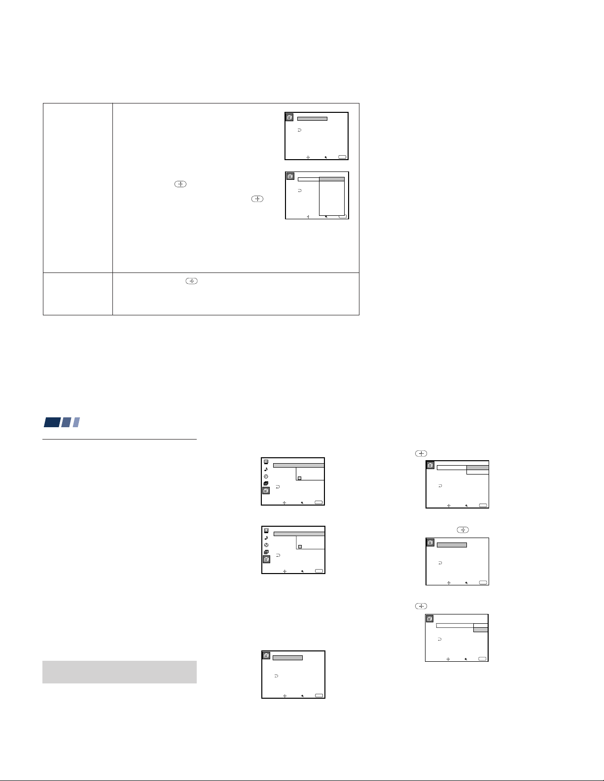
Video Label
Easy recognition of
connected
equipment
(e.g. SAT, VHS,
etc.)
This feature allows you to label each input mode so
that you can easily identify the connected equipment
(e.g. you can label VIDEO 1 IN as VHS).
With the Video Label window open:
1 Press V or v to select the input mode you want to
label and press
2 Press V or v to select the label and press
.
.
Video Label Options:
Video Label
VIDEO1:
VIDEO2:
VIDEO3:
Move Select Exit
Video Label
VIDEO1:
Video1
VIDEO2:
VIDEO3:
AV RECEIVER
Move Select Exit
VIDEO1
VIDEO2
VIDEO3
MENU
VHS
8mm
Beta
LD
SAT
DVD
DTV
Skip
MENU
VIDEO 1: VIDEO 1, VHS, 8mm, Beta, LD, SAT, DVD, AV RECEIVER, DTV,
Skip
VIDEO 2/3: VIDEO 2/VIDEO 3, VHS, 8mm, Beta, LD, SAT, DVD, DTV, Skip
If you select “Skip,” your projection TV will skip this connection when you scan
through video sources using the TV/VIDEO button.
Flash Focus
Automatic
convergence
adjustment
Select Yes and press to start Flash Focus adjustment. When the
adjustment is completed, the cross pattern on the screen becomes white. (for
details, see page 15)
Select No to cancel Flash Focus.
Adjusting Y our SET UP (menus) (contin ued)
Using the Parental Control
Feature
The TV programs and movies shown on TV
are given a rating signal based on the
following rating systems.
In U.S.A.: U.S. Television Parental
Guidelines to rate television programs (U.S.
TV ratings), and Motion Picture Association
of America (MPAA) Guidelines to rate
movies including those shown on TV (movie
ratings)
In Canada: Canadian English Language
ratings to rate television programs in English,
and Canadian French Language ratings to
rate those in French.
To block programs you feel are unsuitable for
your children, you need to set the TV for the
desired rating systems. Sony’s predetermined
ratings are also available.
See pages 39 to 41 for a description of the
ratings.
The Parental Control feature of the TV
functions by receiving the rating signal from
your local broadcasting station or cable
service provider.
Activating the Parental Control
Feature
First, set a password, then select your desired
rating from Sony’s predetermined ratings.
32
1 Select “Parental Control” from the Set Up
menu. (see page 30)
Set Up
Parental Control
Caption Vision:
Language:
Video Label
Flash Focus: No
ch
Move Select Exit
Set New
Password
_ _ _ _
MENU
2 Enter a four digit password* using the 0–
9 buttons.
* Do not enter “4357” corresponding to “HELP”
on a phone number pad. (see page 39)
Set Up
Parental Control
Caption Vision:
Language:
Video Label
Flash Focus: No
ch
Move Select Exit
Confirm
Password
_ _ _ _
MENU
3 To confirm the password, re-enter the
same password with the 0–9 buttons.
Your password is stored and the Parental
Control menu automatically appears.
If you want to change the password, see
page 38.
Parental Control
Country: U.S.A.
Parental Lock:
Rating: Child
Change Password
Move Select Exit
Off
MENU
4 Make sure that “Country ”is highlighted,
and press .
Parental Control
Country: U.S.A.
U.S.A.
Canada
Parental Lock:
Rating: Child
Change Password
Move Select Exit
Off
MENU
5 Press V or v to select your country (U.S.A.
or Canada), and press
Parental Control
Country: U.S.A.
Parental Lock:
Rating: Child
Change Password
Move Select Exit
.
Off
MENU
6 Press V or v to select “Parental Lock,”
and press .
Parental Control
Country: U.S.A.
Parental Lock:
Rating: Child
Change Password
Move Select Exit
On
Off
Off
MENU
31
– 24 –
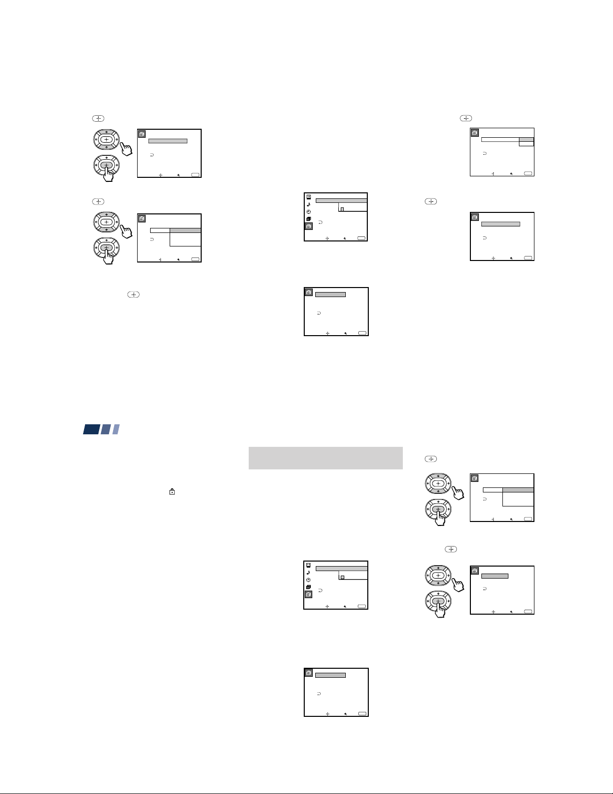
7 Press V or v to select “On,” and press
.
Parental Control
Country: U.S.A.
Parental Lock:
Rating: Child
Change Password
Move Select Exit
On
MENU
8 Press V or v to select “Rating,” and press
.
Parental Control
Country: U.S.A.
Parental Lock:
Rating:
ChangePassword
Ages up to 6
Move
Young Adult
Custom
Select Exit
On
Child
Youth
MENU
9 Press V or v to select a desired rating
(“Child,” “Youth” and “Young Adult”),
and press
If you want to select the ratings from
“Custom,” go to step 4 of “Selecting a
Custom Rating in U.S.A.” on page 34 or
“Selecting a Custom Rating in Canada”
on page 37, according to your “Country”
setting.
10
Press MENU to exit the menu.
.
To deactivate the Parental Control
feature
If you set “Parental Lock” in the Parental
Control menu to “Off,” the Parental Control
feature will not work and you can view all
TV programs and movies shown on TV.
1 Select “Parental Control” from the Set Up
menu. (see page 30)
Set Up
Parental Control
Caption Vision: CC1
Password
_ _ _ _
Language:
Video Label
Flash Focus: No
ch
Move Select Exit
MENU
2 Enter your four digit password using the
0-9 buttons.
The Parental Control menu appears.
Parental Control
Country: U.S.A.
Parental Lock:
Rating: Child
Change Password
Move Select Exit
On
MENU
3 Press V or v to select “Parental Lock,”
and press
.
Parental Control
Country: U.S.A.
Parental Lock:
Rating: Child
Change Password
Move Select Exit
On
Off
Off
MENU
4 Press V or v to select “Off,” and press
.
Parental Control
Country: U.S.A.
Parental Lock:
Rating: Child
Change Password
Move Select Exit
Off
MENU
5 Press MENU to exit the menu.
33
Adjusting Y our SET UP (menus) (contin ued)
To unlock the Parental Control feature
temporarily
When you select a Parental Control program,
no sound or picture except for a channel
number will appear. The
displayed. To view the program, follow the
steps below.
1 Press ENTER to display the “Password”
screen.
2 Enter your password using the 0–9
buttons. Parental Control will be canceled
(“Parental Lock” set to “Off”) until you
turn your projection TV off.
34
indicator is
Selecting a Custom Rating in
U.S.A.
If you want to select the ratings to be blocked
from “Custom” once you have activated the
Parental Control feature (page 33), follow the
procedure below.
For a detailed description of each rating, see
“What the Ratings Mean” on pages 39 to 41.
1 Select “Parental Control” from the Set Up
menu. (see page 30)
Set Up
Parental Control
Caption Vision: CC1
Password
_ _ _ _
Language:
Video Label
Flash Focus: No
ch
Move Select Exit
MENU
2 Enter your four digit password using the
0–9 buttons.
The Parental Control menu appears.
Make sure that “Country” is set to
“U.S.A.”
Parental Control
Country: U.S.A.
Parental Lock:
Rating: Child
Change Password
Move Select Exit
On
MENU
3 Press V or v to select “Rating,” and press
.
Parental Control
Country: U.S.A.
Parental Lock:
Rating:
ChangePassword
Ages up to 6
Move
Young Adult
Custom
Select Exit
On
Child
Youth
MENU
4 Press V or v to select “Custom,” and
press
.
Custom Rating
TV Rating
Movie Rating
Unrated: View All
Select category
Move
Select Exit
MENU
– 25 –
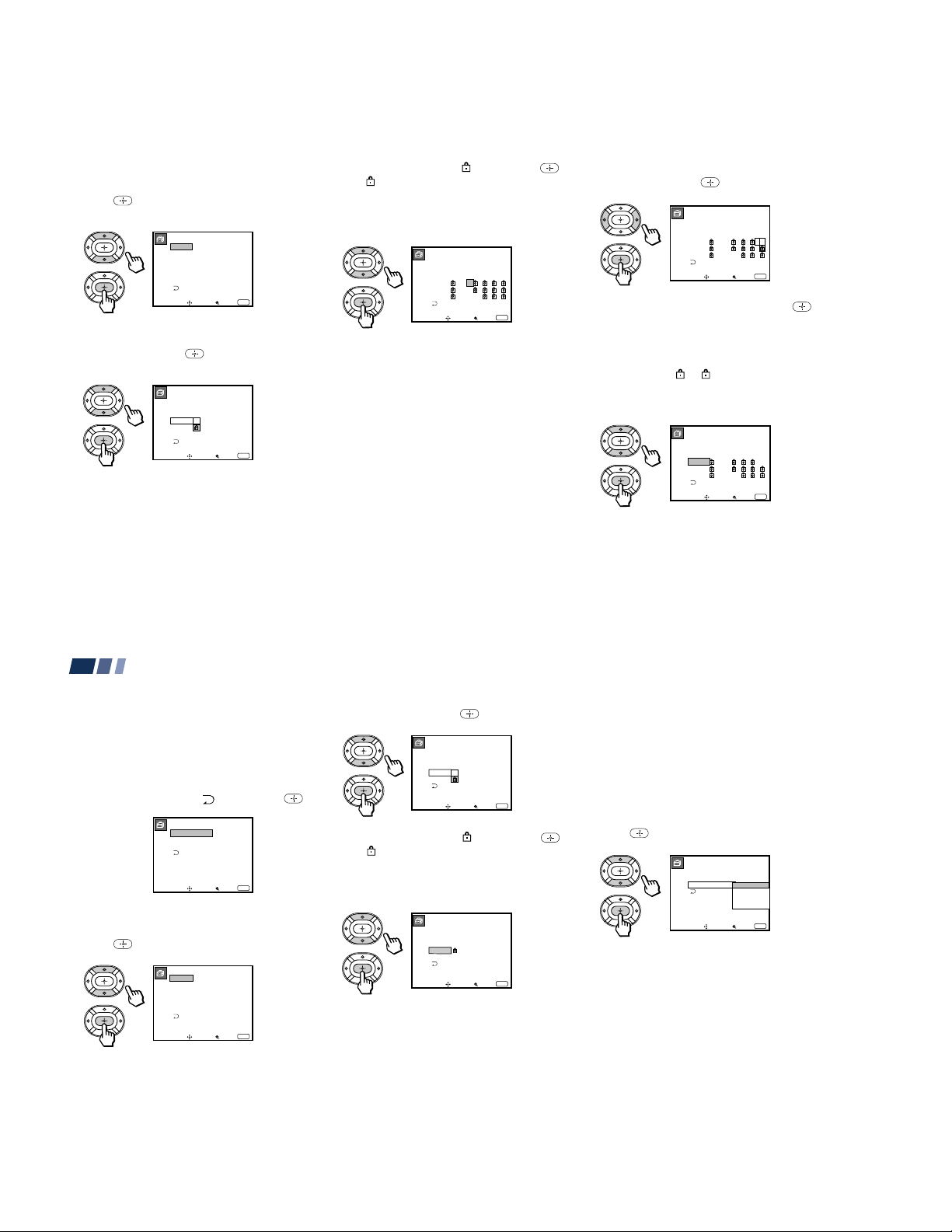
First, select a TV rating.
Custom Rating
Move
No block
Select Exit
MENU
TV Rating
Movie Rating
Unrated: View All
TV
Movie
Both
View All
TV
Movie
Both
5 Press V or v to select “TV Rating,” and
press
.
TV Rating
_
TV–Y
_ :FV _
TV–Y7
_
TV–G
_ :D _ L _ S _ V _
TV–PG
_ :D _ L _ S _ V _
TV–14
_ : L _ S _ V _
TV–MA
Select rating
Move
Select Exit
MENU
6 Press V or v to select the TV rating to be
TV Rating
_
TV–Y
_ :FV _
TV–Y7
_
TV–G
_ :D _ L _ S _ V _
TV–PG
_ :D _ L _ S _ V _
TV–14
_
: L _ S _ V _
TV–MA
Allow rating
Move
Select Exit
.
MENU
blocked, and press
7 Press V or v to select “ ,” and press .
indicator automatically appears
The
beside the selected rating and all “higher”
ratings, indicating that the programs that
match the ratings will be blocked.
TV Rating
_
TV–Y
_ :FV _
TV–Y7
_
TV–G
– :D – L – S – V –
TV–PG
– :D – L – S – V –
TV–14
– : L – S – V
TV–MA
Select category
Move
Some ratings have additional content
ratings called “extenders.” The extenders
are defined as follows: D (sexually
suggestive Dialog), FV (Fantasy
Violence), L (coarse Language), S (Sexual
situations) and V (Violence). By setting
the extenders, you can define additional
viewing limits. For more details of
extenders, see page 41.
All of the extenders included in the
selected ratings will be blocked. If you
wish to allow any of them to be viewed,
go to step 8.
Select Exit
MENU
8 Press B or b to select the extender to be
viewed, and press .
TV Rating
_
TV–Y
_ :FV _
TV–Y7
_
TV–G
– :D – L – S – V –
TV–PG
– :D – L – S – V –
TV–14
– : L – S – V
TV–MA
Block content
Move
Select Exit
MENU
9 Press V or v to select “–,” and press .
“–” appears beside the selected extender,
indicating that the programs that match
the extender can be viewed.
If you select “
show that the programs that match the
extender will be blocked again.
,” is displayed to
TV Rating
_
TV–Y
_ :FV _
TV–Y7
_
TV–G
– :D – L – S – V _
TV–PG
– :D – L – S – V –
TV–14
– : L – S – V
TV–MA
Select category
Move
Select Exit
MENU
(continued)
35
Adjusting Y our SET UP (menus) (contin ued)
10
Repeat steps 8 and 9 for other extenders.
All programs that match the ratings you
select and higher, except for the
extenders that were canceled, will be
blocked.
11
After setting of the TV rating is complete,
press V or v to select “
Custom Rating
Second, select a movie rating.
12
Press V or v to select “Movie Rating,” and
press
.
Movie Rating
36
,” and press .
TV Rating
Movie Rating
Unrated: View All
Select category
Move
Select Exit
–
G
–
PG
–
PG–13
–
R
–
NC–17
–
X
Select rating
Move
Select Exit
MENU
MENU
13
Press V or v to select the movie rating to
be blocked, and press
Movie Rating
G
PG
PG–13
R
NC–17
X
Block rating
Move
14
Press V or v to select “ ,” and press .
–
–
–
–
–
–
Select Exit
.
MENU
The indicator automatically appears
beside the selected rating and all “higher”
ratings, indicating that the programs that
match the ratings will be blocked.
Movie Rating
–
G
–
PG
–
PG–13
–
R
NC–17
–
X
Select rating
Move
15
Press MENU to exit the menu.
Select Exit
MENU
To block TV programs and/or movies
for which a rating signal is not given
(NR and N/A)
For a description of the NR and N/A ratings,
see page 40.
1 Perform steps 1–4 of “Selecting a Custom
Rating in U.S.A.” on page 34.
2 Press V or v to select “Unrated,” and
press .
– 26 –
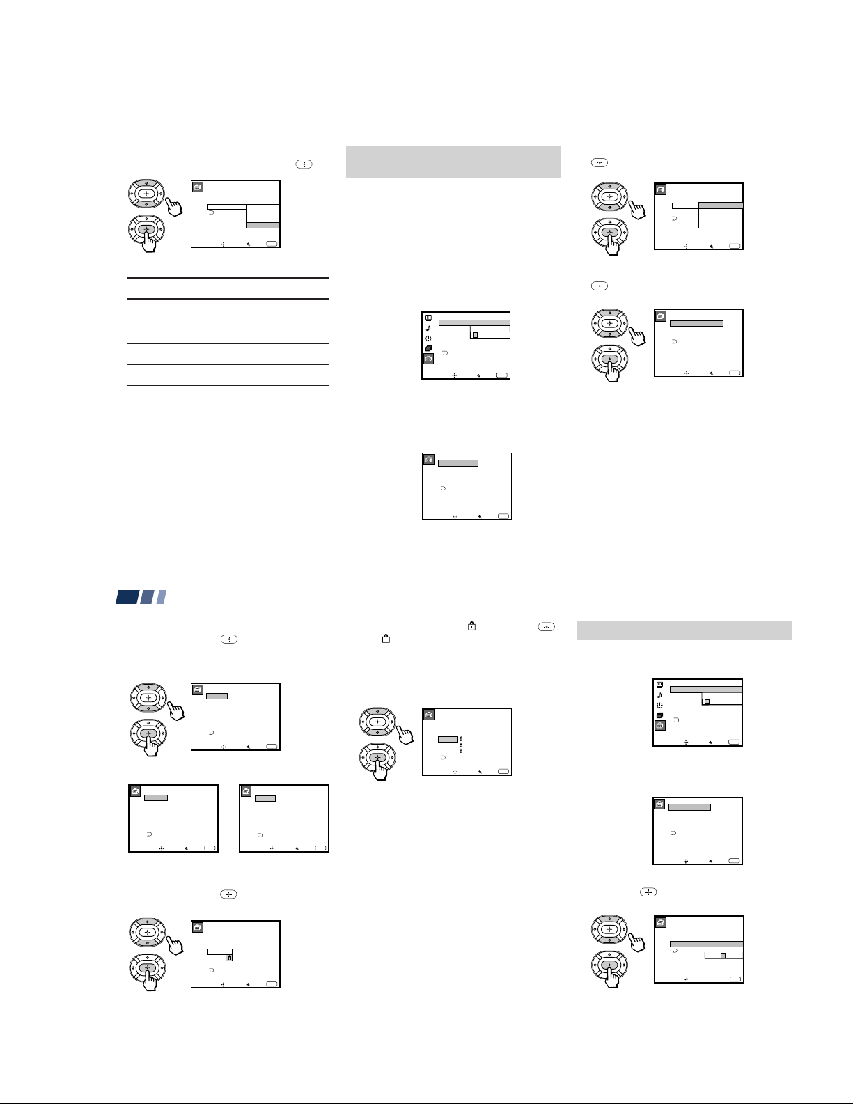
3 Press V or v to select the type of
French Rating
Move
Select rating
Select Exit
MENU
G
8 ans+
13 ans+
16 ans+
18 ans+
_
_
_
_
_
programs to be blocked, and press .
Custom Rating
TV Rating
Movie Rating
Unrated: View All
View All
TV
TV
Movie
Movie
Both
Both
Block all unrated
programming
Move
To block ...
No program
(to view any unrated TV
program and movie)
Unrated TV programs
Unrated movies
Unrated TV programs and
movies
Select Exit
MENU
Select ...
View All
TV
Movie
Both
4 Press MENU to exit the menu.
Selecting a Custom Rating in
Canada
If you want to select the ratings to be blocked
from “Custom” once you have activated the
Parental Control feature (page 33), follow the
procedure below.
For a detailed description of each rating, see
“What the Ratings Mean” on pages 41 and
42.
1 Select “Parental Control” from the Set Up
menu. (see page 30)
Set Up
Parental Control
Caption Vision: CC1
Password
_ _ _ _
Language:
Video Label
Flash Focus: No
ch
Move Select Exit
MENU
2 Enter your four digit password using the
0–9 buttons.
The Parental Control menu appears.
Make sure that “Country” is set to
“Canada.”
Parental Control
Country: Canada
Parental Lock:
Rating: Child
Change Password
On
3 Press V or v to select “Rating,” and press
.
Parental Control
Country: Canada
Parental Lock:
Rating:
ChangePassword
Ages up to 6
Move
Young Adult
Custom
Select Exit
On
Child
Youth
MENU
4 Press V or v to select “Custom,” and press
.
Custom Rating
English Rating
French Rating
U.S.A. Rating
Select category
Move
Select Exit
MENU
(continued)
Adjusting Y our SET UP (menus) (contin ued)
5 Press V or v to select the rating you want
to block, and press
The selected rating appears.
Canadian English Rating
Canadian French Rating U.S. TV Rating
6 Press V or v to select the TV rating to be
blocked, and press
Example: Canadian English Rating
38
.
English Rating
_
C
_
G
_
C8+
_
PG
_
14+
_
18+
Select rating
Move
Select Exit
.
English Rating
_
C
_
G
_
C8+
_
PG
14+
_
18+
Allow rating
Move
Select Exit
MENU
U.S.A. Rating
_
TV–Y
_ :FV _
TV–Y7
_
TV–G
_ :D _ L _ S _ V _
TV–PG
_ :D _ L _ S _ V _
TV–14
_
: L _ S _ V _
TV–MA
Select rating
Move
Select Exit
MENU
Move Select Exit
7 Press V or v to select “ ,” and press .
The
indicator automatically appears
beside the selected rating and all
“higher” ratings, indicating that the
programs that match the ratings will be
blocked.
English Rating
_
C
_
G
_
C8+
PG
14+
18+
Select rating
Move
Select Exit
Some U.S. TV ratings have additional
content ratings called “extenders,” such
as D, FV, L, S and V. By setting the
MENU
extenders, see steps 7 to 10 of “Selecting a
Custom Rating in U.S.A.” on pages 35
and 36. For more details of extenders, see
page 41.
All of the extenders included in the
selected ratings will be blocked. If you
wish to allow any of them to be viewed,
go to step 8.
8 Press MENU to exit the menu.
MENU
37
Changing the Password
1 Select “Parental Control” from the Set Up
menu. (see page 30)
MENU
2 Enter your four digit password using the
0–9 buttons.
The Parental Control menu appears.
Set Up
Parental Control
Caption Vision: CC1
Language:
Video Label
Flash Focus: No
ch
Move Select Exit
Parental Control
Country: U.S.A.
Parental Lock:
Rating: Child
Change Password
Move Select Exit
Password
_ _ _ _
MENU
On
MENU
3 Press V or v to select “Change Password,”
and press
.
Parental Control
Country: U.S.A
Parental Lock: On
Rating:
Change Password
Use [0-9] to enter
new four digit
password
Move Exit
New
Child
____
MENU
– 27 –
4 Enter a new four digit password using
the 0–9 buttons.
Parental Control
Country: U.S.A
Parental Lock: On
Rating:
Change Password
Confirm password
Move Exit
Confirm
Child
____
MENU
5 Enter the password set in step 4 again to
confirm.
If you entered it incorrectly, “Password
incorrect” appears.
Re-enter the correct password.
6 Press MENU to exit the menu.
If you have forgotten your password
In step 2 of “Changing the Password” on
page 38, enter the master password “4357”
(corresponding to “HELP” on a phone
number pad). You can then store a new
password.
Notes:
• If you entered “4357” as your password
the first time, you cannot store a new
password. (see step 2 of “Activating the
Parental Control Feature” on page 32)
• When you select a Parental Control
program and the
indicator is
displayed on the screen, you cannot view
that program even if you enter “4357.”
(see “To unlock the Parental Control
feature temporarily” on page 34)
What the Ratings Mean
Ratings in U.S.A.
Sony’s predetermined ratings
These are original ratings that Sony
predetermined according to the viewer’s age.
Each rating allows you to view the certain
programs, as follows.
See pages 40 and 41 for a description of each
rating.
Child: Suitable for children under the age of
6.
Viewable U.S. movie ratings: G, NR, and N/A
Viewable U.S. TV ratings: TV-Y, TV-G, and
TV-NR
Youth: Suitable for children aged 7 and
older.
Viewable U.S. movie ratings: G, PG, NR, and
N/A
Viewable U.S. TV ratings: TV-Y, TV-Y7, TVG, TV-PG, and TV-NR
Young Adult: Suitable for children aged 13
and older.
Viewable U.S. movie ratings: G, PG, PG-13,
NR, and N/A
Viewable U.S. TV ratings: TV-Y, TV-Y7, TVG, TV-PG, TV-14, and TV-NR
(continued)
39
Adjusting Y our SET UP (menus) (contin ued)
U.S. movie ratings
U.S. movie ratings are for movies (including
those shown on TV) rated according to the
Motion Picture Association of America
(MPAA) Guidelines.
G (General Audiences—All Ages
Admitted): In G-rated films no strong words
are used, the violence is at a minimum,
nudity and sex scenes are not present, nor is
there any drug use.
PG (Parental Guidance Suggested. Some
Material May Not Be Suitable For
Children): This is a film which may need to
be monitored first by parents.
PG-13 (Parents Strongly Cautioned. Some
Material May Be Inappropriate For
Children Under 13): Parents are alerted to be
very careful about the attendance of their
under-teenage children when viewing.
R (Restricted, Under 17 Require
Accompanying Parent Or Adult Guardian):
This film includes hard language, tough
violence, nudity, drug abuse or other
elements of concern.
40
NC-17 or X (No One 17 Or Under
Admitted.): This is a film that most parents
would consider not suitable for children
aged 17 and under. There may be violence,
sex, abberrational behavior, drug abuse or
other elements of concern.
NR (Not Rated): This is a film that a
producer has not rated, intending to have his
film widely released.
N/A (Not Applicable): This is a film that a
producer considers outside the scope of the
MPAA ratings.
Note:
• NR and N/A ratings are shown together
as “Unrated” in the menu.
U.S. TV ratings
U.S. TV ratings are for TV programs rated
according to the U.S. Television Parental
Guidelines.
TV-Y (All Children): This program is
designed for young children aged 2–6 and is
appropriate for all children.
TV-Y7 (Directed to Older Children): This
program is designed for children aged 7 and
above. Themes and elements in this program
may include mild fantasy violence or
slapstick violence, or may frighten children
under the age of 7.
TV-G (General Audience): Most parents
would find this program suitable for all ages.
It contains little or no violence, no strong
language and little or no sexual dialog or
situations.
TV-PG (Parental Guidance Suggested):
This program contains some material that
parents may find unsuitable for younger
children.
TV-14 (Parents Strongly Cautioned): This
program contains some material that many
parents would find unsuitable for children
under the age of 14.
TV-MA (Mature Audience Only): This
program is specifically designed to be
viewed by adults and therefore may be
unsuitable for children under the age of 17.
– 28 –

TV-NR (Not Rated/Unrated): This is a
program broadcast without any rating, such
as news, news flashes or sports.
Note:
The TV-NR rating is shown as “Unrated” in
the menu.
About the extenders of U.S. TV ratings
TV-Y7, TV-PG, TV-14 and TV-MA ratings
have additional content ratings called
“extenders” to define additional viewing
limits. The extenders are defined as follows:
D (sexually suggestive Dialog): Programs
containing suggestive dialog, or sexual
innuendo
FV (Fantasy Violence): Programs containing
cartoon violence occurring in TV-Y7
programs only
L (coarse Language): Programs containing
coarse language
S (Sexual situations): Programs containing
sexual content
V (Violence): Programs containing violence
There may be some profanity, violence or
brief nudity in these programs.
Ratings in Canada
Sony’s predetermined ratings
These are original ratings that Sony
predetermined according to the viewer’s age.
Each rating allows you to view the certain
programs, as follows.
See the right column and page 42 for a
description of each rating.
Child: Suitable for children under the age of
7.
Viewable Canadian English Language
ratings: C and G
Viewable Canadian French Language
ratings: G
Viewable U.S. TV ratings: TV-Y, TV-G, and
TV-NR
Youth: Suitable for children aged 8 and
older.
Viewable Canadian English Language
ratings: C, G, C8+ and PG
Viewable Canadian French Language
ratings: G and 8 ans+
Viewable U.S. TV ratings: TV-Y, TV-Y7, TVG, TV-PG, and TV-NR
Young Adult: Suitable for children aged 14
and older.
Viewable Canadian English Language
ratings: C, G, C8+, PG and 14+
Viewable Canadian French Language
ratings: G, 8 ans+, 13 ans+
Viewable U.S. TV ratings: TV-Y, TV-Y7, TVG, TV-PG, TV-14, and TV-NR
Canadian English Language ratings
The Canadian English Language Ratings are
for TV programs in English broadcast in
Canada.
C (Programming intended for children
under age 8): There will be no realistic
scenes of violence or no offensive language,
nudity or sexual content. Careful attention is
paid to themes, which could threaten
children’s sense of security and well-being.
G (General Audience): Will contain very
little violence, either physical or verbal or
emotional. There may by some inoffensive
slang, no profanity and no nudity.
(continued)
41
Adjusting Y our SET UP (menus) (contin ued)
C8+ (Programming generally considered
acceptable for children 8 years and over to
watch on their own): Violence will not be
portrayed as the preferred, acceptable, or
only way to resolve conflict; or encourage
children to imitate dangerous acts which
they may see on television. There will be no
profanity, nudity or sexual content.
PG (Parental Guidance): Programming
intended for a general audience but which
may not be suitable for younger children.
Parents may consider some content
inappropriate for unsupervised viewing by
children aged 8 - 13.
14+ (Programming contains themes or
content which may not be suitable for
viewers under the age of 14): Parents are
strongly cautioned to exercise discretion in
permitting viewing by pre-teens and early
teens.
18+ (Adult): May contain violence integral
to the development of the plot, character or
theme, intended for adult audiences. May
contain graphic language and explicit
portrayals of nudity and/or sex.
42
E (Exempt): Exempt programming includes:
news, sports documentaries and other
information programming: talk shows,
music videos, and variety programming.
Note:
The E (Exempt) rating is not shown in the
menu.
Canadian French Language ratings
The Canadian French Language Ratings are
for TV programs in French broadcast in
Canada.
G (General): Programming intended for
audience of all ages. Contains no violence, or
the violence it contains is minimal or is
depicted appropriately with humor or
caricature or in an unrealistic manner.
8 ans+ (8+ General - Not recommended for
young children): Programming intended for
a broad audience but contains light or
occasional violence that could disturb young
children. Viewing with an adult is
recommended for young children (under the
age of 8).
13 ans+ (Programming may not suitable for
children under the age of 13): Viewing with
an adult is strongly recommended for
children under 13.
16 ans+ (Programming is not suitable for
children under the age of 16): Contains
frequent scenes of violence or intense
violence.
18 ans+ (Programming restricted to adults):
Contains constant violence or scenes of
extreme violence.
E (Exempt): Exempt programming.
Note:
The E (Exempt) rating is not shown in the
menu.
– 29 –
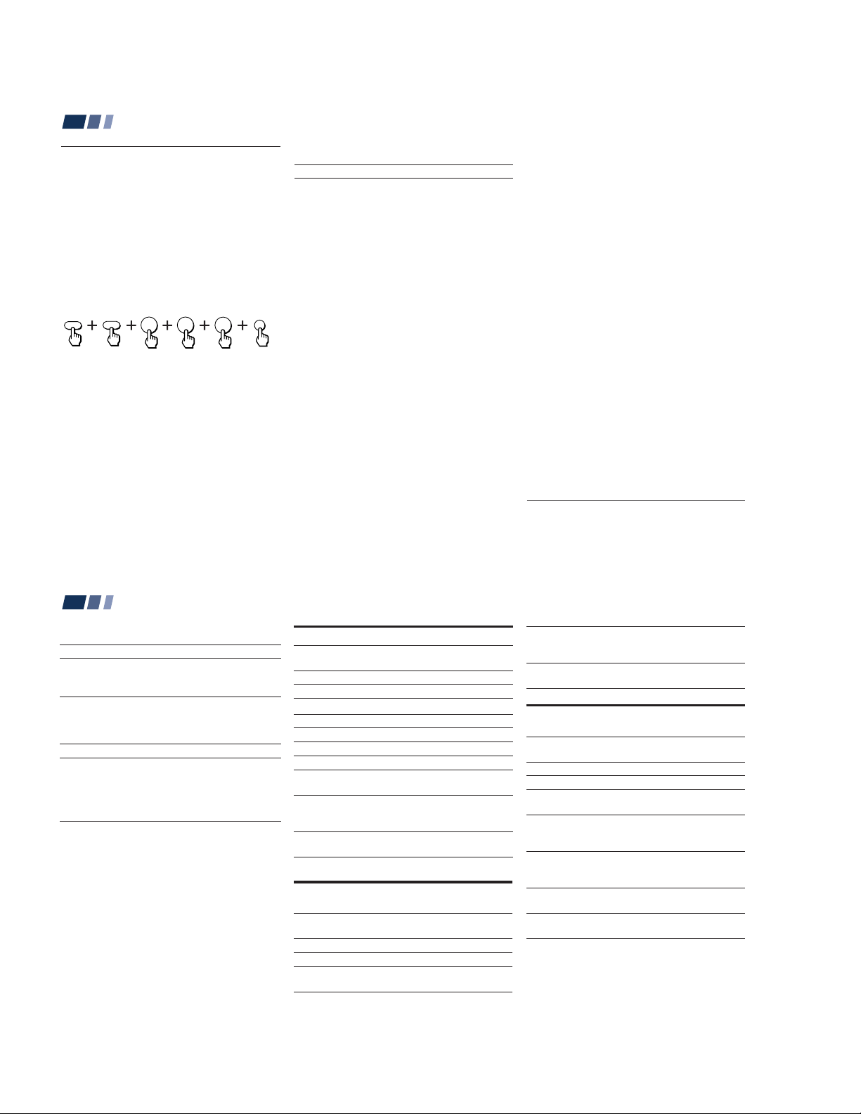
Operating Video Equipment
Setting the Manufacturer's
Code
You can use the supplied remote control to
operate Sony or non-Sony video equipment
that has an infrared sensor.
Press CODE SET, DVD/VTR (FUNCTION),
and the 0-9 buttons to enter the
manufacturer’s code number (see the
following chart), then press ENTER.
For example, to operate a Sony 8mm VCR:
FUNCTION
CODE SET
DVD/VTR
3
0
If the remote control doesn’t work
• See the tips on page 45.
ENTER
2
VCR manufacturer code numbers
Manufacturer Code
Sony (VHS VCR) 301
Sony (8mm VCR) 302
Sony (Beta, ED Beta, VCRs) 303
Aiwa 338
Admiral (M. Ward) 327
Audio Dynamic 314, 337
Bell & Howell (M. Ward) 330
Broksonic 319, 317
Canon 309, 308
Citizen 332
Craig 302, 332
Curtis Mathis 304, 338, 309
Daewoo 341, 312, 309
DBX 314, 336, 337
Dimensia 304
Emerson 319, 320, 316, 317, 318, 341
Fisher 330, 335
Funai 338
General Electric 329, 304, 309
Go Video 340, 339, 322
Goldstar 332
Hitachi 306, 304, 305, 338
Instant Replay 309, 308
JC Penney 309, 305, 304, 330, 314, 336, 337
JVC 314, 336, 337
Kenwood 314, 336, 332, 337
LXI (Sears) 332, 305, 330, 335, 338
Magnavox 308, 309, 310
Marantz 314, 336, 337
Marta 332
Memorex 309, 335
Minolta 305, 304
Mitsubishi/MGA 323, 324, 325, 326
Multitech 325, 338, 321
NEC 314, 336, 337
Olympic 309, 308
Optimus 327
Panasonic 308, 309, 306, 307
Pentax 305, 304
Philco 308, 309
Philips 308, 309, 310
Pioneer 308
Quasar 308, 309, 306
RCA/PROSCAN 304, 305, 308, 309, 311,
Realistic 309, 330, 328, 335, 324, 338
Sansui 314
Samsung 322, 313, 321
Sanyo 330, 335
Scott 312, 313, 321, 335, 323, 324, 325, 326
Sharp 327, 328
Signature 2000 (M. Ward) 338, 327
Sylvania 308, 309, 338, 310
Symphonic 338
SV2000 338
Tashiro 332
Tatung 314, 336, 337
Teac 314, 336, 338, 337
Technics 309, 308
Teknica 338
Toshiba 312, 311
Wards 327, 328, 335, 331, 332
Yamaha 330, 314, 336, 337
Zenith 331
329, 312, 313, 310
43
Operating Video Equipment (continued)
MDP manufacturer code numbers
Manufacturer Code
Sony 701
Panasonic 704, 710
Mistubishi 702
DVD Player manufacturer code
numbers
Manufacturer Code
Sony 751
Panasonic 753
Pioneer 752
RCA 755
Toshiba 754
Tips
z
• In some rare cases, you may not be able to operate
your non-Sony video equipment with the supplied
remote control. In this case, please use the
equipment's own remote control.
• When you remove the batteries, the code number may
revert to the factory setting.
To operate video equipment
1 Press DVD/VTR (FUNCTION).
2 Use the VCR/DVD/MDP operation
buttons indicated in the following tables.
44
Operating a VCR using the remote control
To turn On/Off
To select a channel
To change channels
To record
To play
To stop
To fast forward
To rewind the tape
To pause
To search the
picture forward or
backward
To change input
mode
Press DVD/VTR (POWER).
[Green Button]
Press the 0 – 9 buttons.
Press CH +/–.
Press ( while pressing r.
Press (.
Press p.
Press ).
Press 0.
Press P. Press again to
resume normal playback.
Press ) or 0 during
playback. Release to
resume normal playback.
Press TV/VTR.
Operating an MDP using the remote
control
To turn On/Off
To play
To stop
To pause
Press DVD/VTR (POWER).
[Green Button]
Press (.
Press p.
Press P. Press again to
resume normal playback.
To search the picture
forward or backward
To search a chapter
forward or backward
Press ) or 0 during
playback. Release to resume
normal playback.
Press CH +/–.
Operating a DVD Player using the remote
control
To turn On/Off
To play
To stop
To pause
To step through
different tracks of
an audio disc
To step through
different chapters
of a video disc
To select tracks
directly
To display the
menu (Set up)
Press DVD/VTR (POWER).
[Green Button]
Press (.
Press p.
Press P. Press again to
resume normal playback.
Press ) to step forward or
0 to step backward.
Press CH + to step forward
or CH – to step backward.
Press 0-9 buttons.
Press MENU.
– 30 –
 Loading...