

Sony KP-51WS500, KP-57WS500, KP-65WS500 Schematic
SERVICE MANUAL
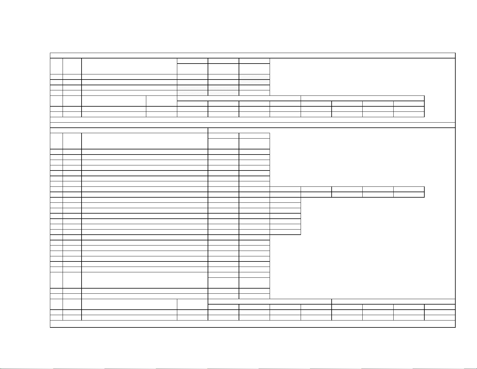
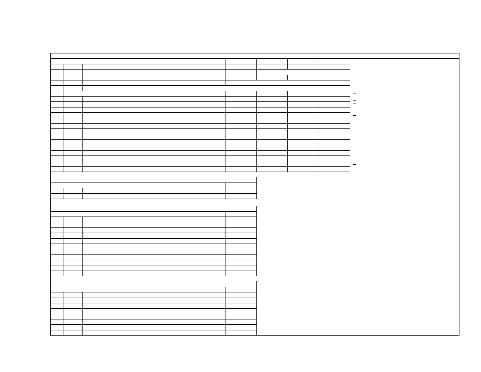
Self Diagnosis
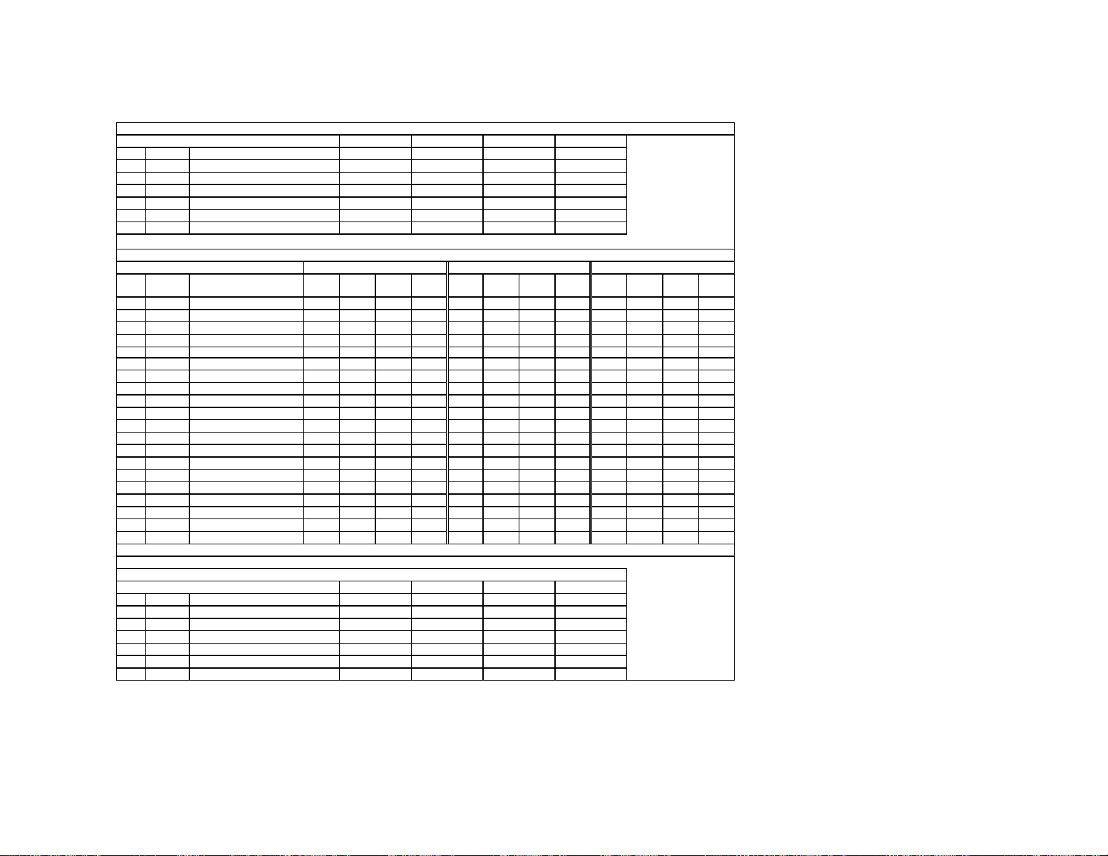
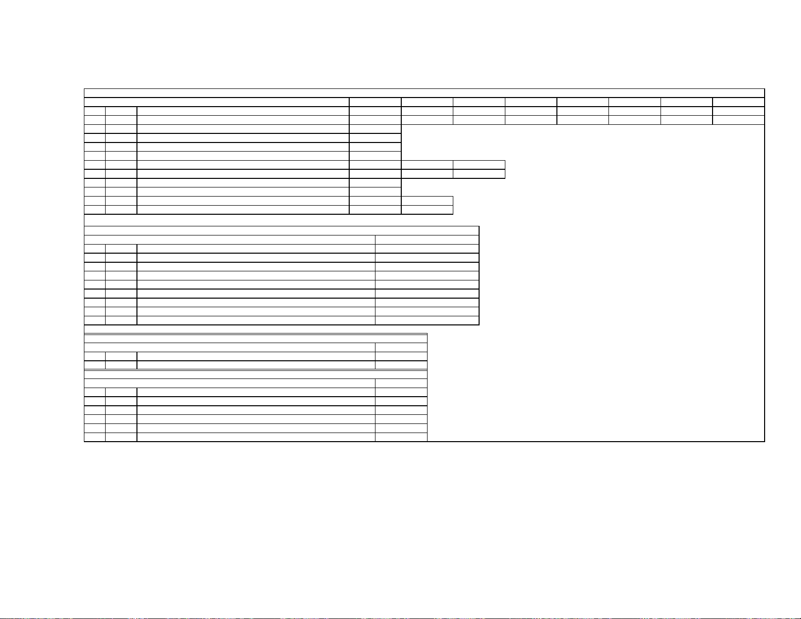
Supported model
MODEL NAME REMOTE COMMANDER DESTINATION CHASSIS NO.
RA-6
CHASSIS
KP-51WS500
KP-57WS500
KP-65WS500
RM-Y909 US/CND SCC-P65HA
RM-Y909 US/CND SCC-P65JA
RM-Y909 US/CND SCC-P65KA
9-965-932-04
KP-65WS500 RM-Y909
COLOR REAR VIDEO PROJECTOR

KP-51WS500/57WS500/65WS500
SELF-DIAGNOSTIC FUNCTION
Self Diagnosis
Supported model
The units in this manual contain a self-diagnostic function. If an error occurs, the STANDBY/TIMER LED will automatically begin to fl ash. The number
of times the LED fl ashes translates to a probable source of the problem. A defi nition of the STANDBY/TIMER LED fl ash indicators is listed in the
instruction manual for the user’s knowledge and reference. If an error symptom cannot be reproduced, the Remote Commander can be used to review
the failure occurrence data stored in memory to reveal past problems and how often these problems occur.
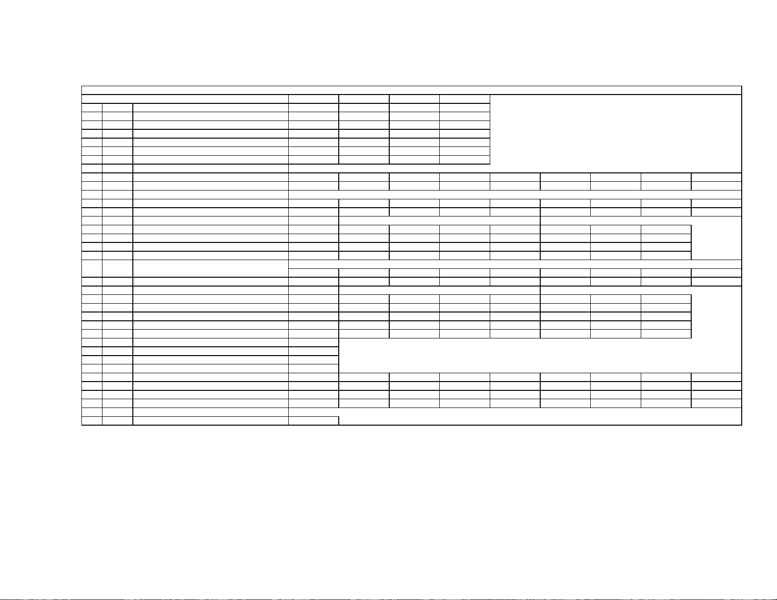
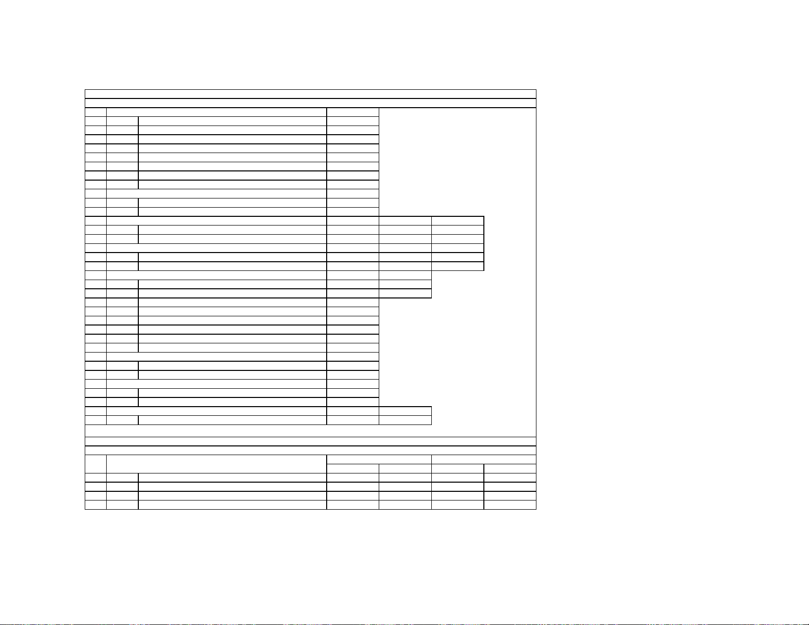
Diagnostic Test Indicators
When an error occurs, the STANDBY/TIMER LED will fl ash a set number of times to indicate the possible cause of the problem. If there is more than
one error, the LED will identify the fi rst of the problem areas.
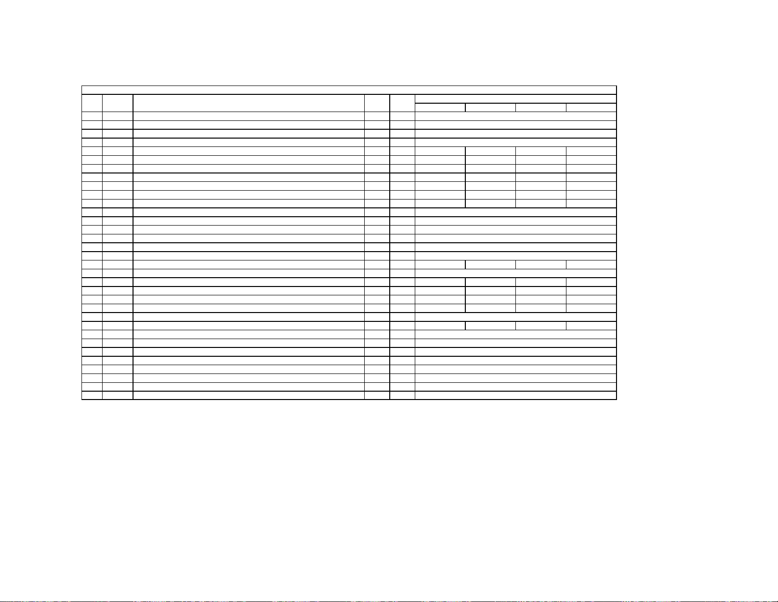
Results for all of the following diagnostic items are displayed on screen. If the screen displays a “0”, no error has occurred.
No. of times
Diagnostic Item
Power does not turn on Does not light
+B overcurrent (OCP)* 2 times
+B overvoltage (OVP) 3 times
Vertical deflection stopped 4 times
White Balance Failure
(Not Balanced)
Low B OCP/OVP
(Overcurrent/Overvoltage) ***
Horizontal deflection stopped 7 times
High-voltage error 8 times
Audio error 9 times
STAND BY /
TIMER
lamp flashes
5times
6times
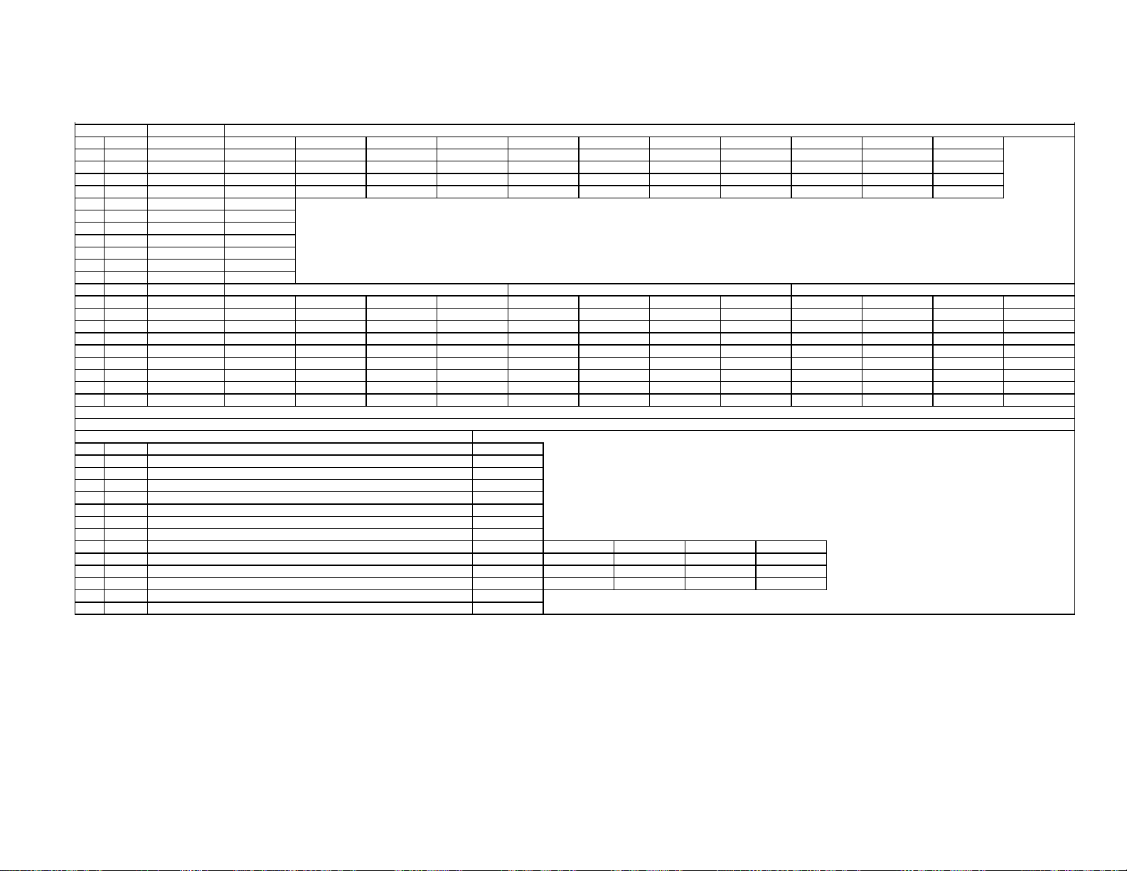
Probable Cause Location Detected Symptoms
• Power cord is not plugged in.
• Fuse is burned out (F6001). (G Board)
• H.OUT (Q8024) is shorted. (D Board)
• +B PWM (Q8035, Q8038) is shorted.
(D Board)
• IC501 is faulty. (G Board)
• IC5002 is faulty. (G Board)
±15V is not supplied. (D Board)
•
• IC8003 is faulty. (A Board)
• Video OUT (IC7101, IC7201, IC7301)
is faulty. (CR, CG, CB Boards)
• CRT drive (IC309) is faulty. (A Board)
• Screen (G2) is improperly adjusted. **
• +5 line is overloaded. (A, B Boards)
• +5 line is shorted. (A, B Boards)
• Q8035, Q8038 is shorted. (D Board)
• T8005 is faulty. (D Board)
•±19V line is shorted. (A, B Boards)
• Power does not come on.
• No power is supplied to the TV.
• AC Power supply is faulty.
• Power does not come on.
• Load on power line shorted.
• Has entered standby mode.
• Has entered standby state after
horizontal raster.
• Vertical deflection pulse is
stopped.
• Power line is shorted, or
power supply is stopped.
• No raster is generated.
• CRT Cathode current detection
reference pulse output is small.
• No picture
• No sound
• IC708 is faulty. (A Board)
• PS701 or PS702 is opened.
(A Board)
* If a +B overcurrent is detected, stoppage of the vertical deflection is detected simultaneously. The symptom that is diagnosed
first by the microcontroller is displayed on the screen.
** Refer to Screen (G2) Adjustments in Section 2-2 of this manual
*** If TIMER or STAND BY indicator blinks six (6) times, unplug the unit and wait 10 minutes before performing the adjustment.
— 7 —
KP-51WS500/57WS500/65WS500
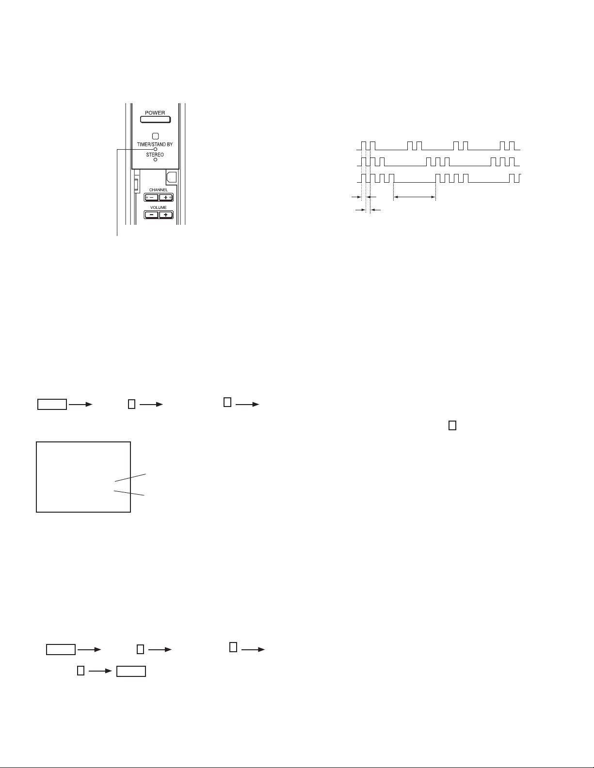
Display of Standby/Timer LED Flash Count
* One blink is not used for self-diagnosis.
< FRONT PANEL >
• EXAMPLE
<Diagnosis Items> <Number of Blinks>
• +B overcurrent 2 times
• +B overvoltage 3 times
• Vertical deflection stop 4 times
Lamp ON : 0.3 seconds
Lamp OFF : 0.3 seconds
TIMER/STAND BY indicator
Release of TIMER STAND BY indicator blinking
The TIMER/STANDBY indicator blinking display is released by turning OFF the power switch on the TV main unit or removing the plug from the
power.
Lamp OFF :
3.0 seconds
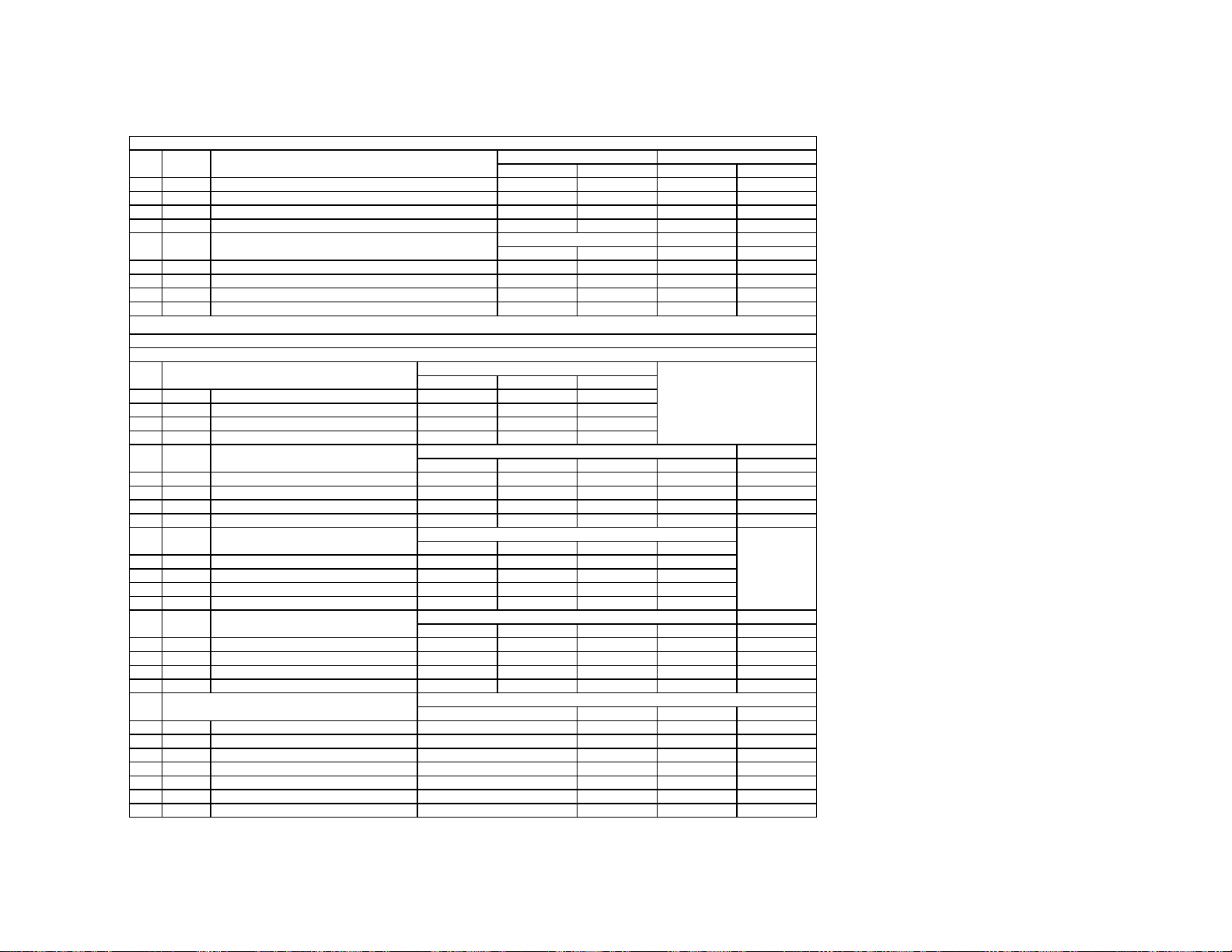
Self-Diagnosis Screen Displays
In cases of malfunctions where it is not possible to determine the symptom such as when the power goes off occasionally or when the screen
disappears occasionally, there is a screen display on whether the malfunction occurred or not in the past (and whether the detection circuit operated
or not) in order to allow confi rmation.
Screen Display Method
Quickly press the remote command button in the following order from the standby state.
Display
Channel
Sound Volume*
5
*Note that this differs from entering the service mode (sound volume
SELF DIAGNOSIS
2 : +B OCP N/A
3 : +B OVP N/A
4 : V STOP 0
5 : AKB 1
10 : WDT 24
Numeral "0" means that no fault
was detected.
Numeral "1" means a fault was detected
one time or more
_
Power ON
)
+
Self-Diagnosis Screen Display
The results display is not automatically cleared. In case of repairs and after repairs, check the self-diagnosis screen and be sure to return the
results display to “ 0 ”.
If the results display is not returned to “ 0 ” it will not be possible to judge a new malfunction after completing repairs.
Method of Clearing Results Display
1. Power off (Set to the standby mode.)
2.
Display
3. Channel
8
Channel
ENTER
Sound Volume
5
(Test reset = Factory preset condition)
+
Power ON (Service Mode)
Method of Ending Self Diagnosis Screen
When ending the self-diagnosis screen completely, turn the power switch OFF on the remote commander or the main unit.
— 8 —
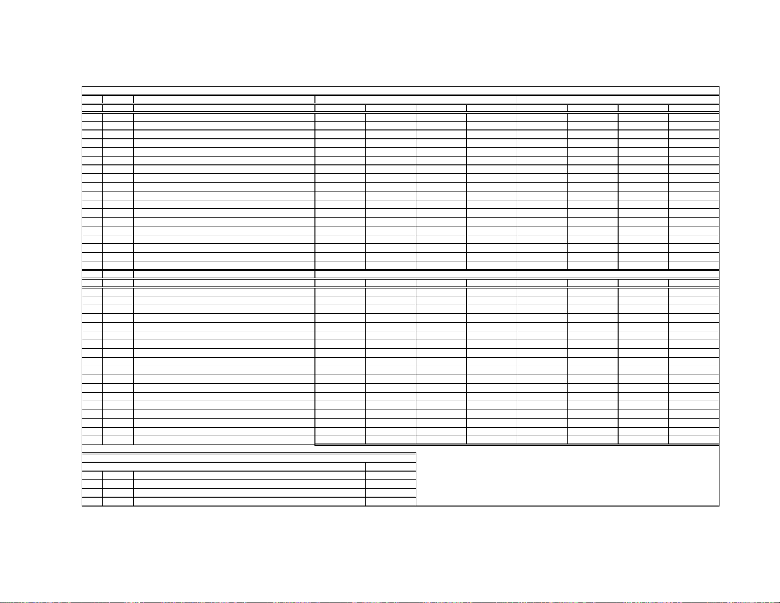
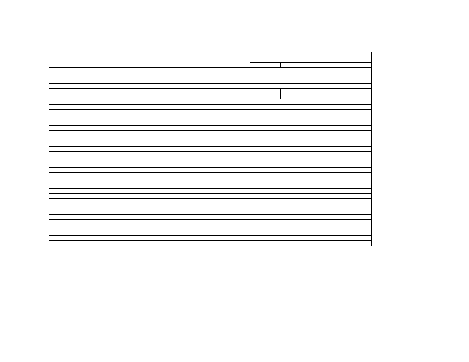
Self-Diagnosis Function Operation
Q8001
Q378
Q378
OCP Low B and +B line detect DET SHORT, and shut-down POWER ON RELAY.
Reset by turning power on/off. In case of +B is loaded approx. 1.5A or more, microcomputer detects it via
IC5005.
KP-51WS500/57WS500/65WS500
OVP In case of +B becomes approx. 150V or more, POWER ON RELAY shuts down and microcomputer detects it via
Reset by turning power on/off just the same as OCP.
Low B Occurs when set +5V is out
V Stop In the case of the V Drive disappearing,
causes the LED to blink.
AKB IK detection. Makes LED blink when microcomputer doesn’t detect IK, returns of
H Stop In case H DRIVE disappears,
Microcomputer receives H Stop data from
HV Stop In case HV becomes 33kV or more,
The microcomputer makes the LED blink.
Audio In case of DC component overlaps the output of Audio Amp., the microcomputer detects it and shuts-down POWER ON RELAY.
The microcomputer makes the LED blink.
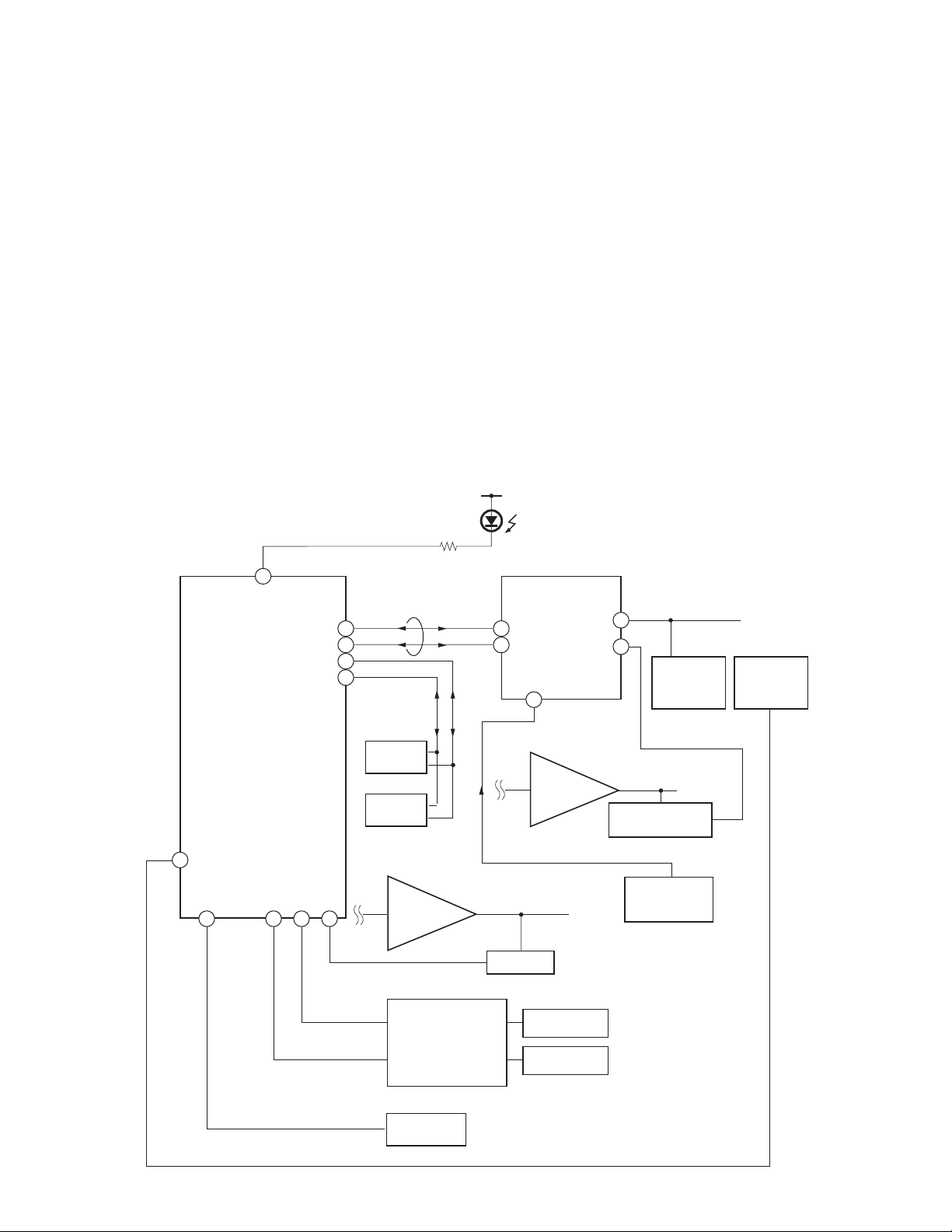
Self-Diagnosis Block Diagram
Q378 detects it and shuts-down POWER ON RELAY.
49
Q8001 detects it and shuts-down the POWER ON RELAY. The microcomputer detects it and
IC309 (CXA2150AQ) 20 seconds or more.
Q378 and makes the LED blink.
IC8006 detects it and shuts-down POWER ON RELAY.
D9101
TIMER/STANDBY
R765
5. AKB
31
28
29
30
BUS
25
26
IC309
CXA2150AQ
Y/C JUNGLE
58
34
35
6. H STOP
Q378
H PULSE
Detector
IC5005.
IC8006
HV Detector
53
43 244544
6. LOW B
8. HV.STOP
IC704
MAIN-CPU
3. OVP
2. OCP
9. Audio
IC702
EEPROM
IC703
EEPROM
Audio AMP
Q714
+5V DETECT
IC708
IC5005
OVP Buffer
OCP Buffer
5. AKB
DC Detect
IC8003
V Drive
OVP DETECT
OCP DETECT
4. V STOP
Q8001
V Pulse Detector
C Board
— 9 —
SECTION 2: SET-UP ADJUSTMENTS
KP-51WS500/57WS500/65WS500
2-1. SCREEN VOLTAGE ADJUSTMENT (COARSE ADJUSTMENT)
1. Receive the Monoscope signal..
2. Set BRIGHTNESS to 50% and PICTURE to minimum.
3. Turn the red VR on the focus block all the way to the left and then
gradually turn it to the right until the retrace line is barely visible.
4. Gradually turn the control to the left until the retrace line disappears.
R G B
SCREEN
R G B
FOCUS
FOCUS Block
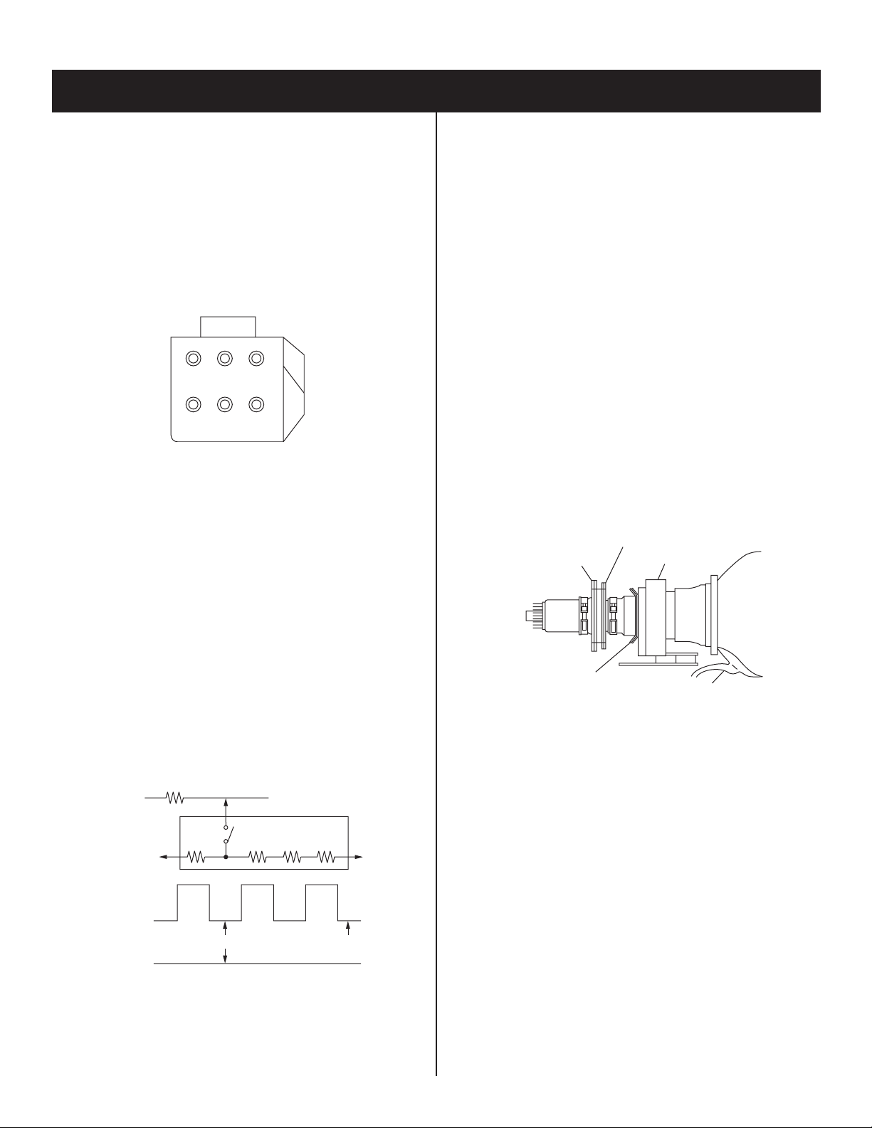
2-2. SCREEN (G2) ADJUSTMENT
(FINE ADJUSTMENT)
If the jig described below is available, it is recommended that the G2
Fine Mode Adjustment be performed to set the screen controls to their
optimal condition. If desired, you can build the jig illustrated below,
using 3-watt resistors. Please note that if the proper voltage is not
obtained with the listed resistor’s values, then increase or decrease one
of the values in the resistor network to obtain the correct voltage.
2-3. DEFLECTION YOKE TILT ADJUSTMENT
1. Connect the color bar generator monoscope pattern to Video 1 input.
2. Cover the red and blue CRT lenses with lens caps to allow only green
to show (or use the method shown in the note below for turning off the
CRTs individually without using lens caps).
3. Loosen the CRT’s deß ection yoke set screw and align the tilt of
the deß ection yoke so that the horizontal bars at the center of the
monoscope pattern are horizontal.
4. After aligning the deß ection yoke fasten it securely to the
funnel-shaped portion (neck) of the CRT.
The tilt of the deß ection yoke is aligned in the mode.
5. Cover the green and blue CRT lenses with lens caps to allow only
green to show (or use the method shown in the note below for turning
off the CRTs individually without using lens caps), then repeat steps
3 and 4 for the red CRT.
Cover the green and red CRT lenses with lens caps to allow only
green to show (or use the method shown in the note below for turning
off the CRTs individually without using lens caps), then repeat steps
3 and 4 for the blue CRT.
Note: If lens caps are unavailable, you can cut off the unnecessary color
beams by controlling the service mode 2150P-2 1 RGBS.
4-pole magnet
2-pole magnet
Deflection yoke
1. Select VIDEO-1 mode no signal applied (the screen must be black).
2. Connect the G2 JIG.
3. SW on JIG.
4. Connect an oscilloscope to the TP7101(KR), TP7202(KG) and
TP7301(KB) of CR board, CG board, and CB board.
5. Adjust red, green, and blue screen voltage to 177.5+/-0.5V with screen
VR on the focus block.
K
G2 JIG
TO CG BOARD
TP7202
(210V)
GND
3.3k 3.9k 5.6k 6.8k
177.5V +/- 0.5V
SW
GND
All resistors are 3W type
pedestal level
Centering magnet
Anode cap
— 15 —

KP-51WS500/57WS500/65WS500
2-4. FOCUS LENS ADJUSTMENT
In this adjustment, use the remote commander while in service mode.
For details on the usage of the service mode and the remote
commander, please refer to section
2-10. ELECTRICAL ADJUSTMENTS BY REMOTE COMMANDER.
1. Loosen the lens screw.
2. Cover the red and blue CRT lenses with lens caps to allow only green
to show (or use the method shown in the note below for turning off the
CRTs individually without using lens caps).
3. Turn the green lens to adjust to the optimum focus point with the
crosshatch signal.
4. Tighten the lens screw.
5. Cover the green and blue CRT lenses with the lens caps to allow only
red to show (or use the method shown in the note below for turning off
the CRTs individually without using lens caps).
6. Turn the red lens to adjust to the optimum focus point with the
crosshatch signal.
7. Tighten the lens screw.
8. Cover the green and red CRT lenses with the lens caps to allow only
blue to show (or use the method shown in the note below for turning
off the CRTs individually without using lens caps).
9. Turn the blue lens to adjust to the optimum focus point with the
crosshatch signal.
10. Tighten the lens screw.
11. After adjusting the items:
2-5. FOCUS VR ADJUSTMENT,
2-6. 2-POLE MAGNET ADJUSTMENT,
2-8. 4-POLE MAGNET ADJUSTMENT,
reconÞ rm the optimum focus point and adjust again if necessary.
2-5. FOCUS VR ADJUSTMENT
1. Set generator to crosshatch.
2. Cover the red and blue CRT lenses with lens caps to allow only green
to show (or use the method shown in the note below for turning off the
CRTs individually without using lens caps).
3. Turn the green focus VR on the focus block to adjust to the optimum
focus point with the crosshatch signal.
4. Cover the green and blue picture lenses with lens caps to allow only
red to show (or use the method shown in the note below for turning off
the CRTs individually without using lens caps).
5. Turn the red focus VR on the focus block to adjust to the optimum
focus point with the crosshatch signal.
6. Cover the green and red picture lenses with lens caps to allow only
blue to show (or use the method shown in the note below for turning
off the CRTs individually without using lens caps).
7. Turn the blue focus VR on the focus block to adjust to the optimum
focus point with the crosshatch signal.
8. After adjusting the items:
2-4. FOCUS LENS ADJUSTMENT,
2-6. 2-POLE MAGNET ADJUSTMENT,
2-8. 4-POLE MAGNET ADJUSTMENT,
reconÞ rm the optimum focus point and adjust again if necessary.
Note: If lens caps are unavailable, you can cut off the unnecessary color
beams by controlling the service mode 2150P-2 1 RGBS.
Scanning line visible.
* Every time 6 is pressed, the test signal changes to:
“crosshatch+video signal” → “crosshatch+borderline(black)” →
”crosshatch(black)” → “dots(black)” → off
Test Signal
Note: If lens caps are unavailable, you can cut off the unnecessary color
beams by controlling the service mode 2150P-2 1 RGBS.
Lens
A
Minimize both A and B.
B
Center of crosshatch
— 16 —
KP-51WS500/57WS500/65WS500
2-6. 2-POLE MAGNET AND CENTERING MAGNET ADJUSTMENT
1. Set the picture mode to PRO and picture to MAX.
2. Either select the PJED Test Pattern dot hatch signal or apply an
external dot signal.
3. Cover the red and blue CRT lenses with lens caps to allow only green
to show (or use the method shown in the note below for turning off the
CRTs individually without using lens caps).
4. Turn the focus VR on the focus block to the left (counter clockwise)
and set it to overfocus to enlarge the spot.
5. Adjust the CRT’s 2-pole magnet so that the small bright spot is in
the center.
6. Align the focus VR on the focus block and set it for the best focus.
7. Apply a Monoscope signal to the set.
8. Adjust the H-CENTERING and V-CENTERING roughly by the
centering magnets.
9. Check 2-pole magnet adjustment. If necessary repeat steps 1-6.
10. Repeat steps 1 through 9 for the red CRT covering the
green and blue CRT lenses with lens caps to allow only
red to show (or use the method shown in the note below
for turning off the CRTs individually without using lens caps) and
adjust the red focus control on the focus block.
11. Repeat steps 1 through 9 for the blue CRT covering the
red and green CRT lenses with lens caps to allow only
blue to show (or use the method shown in the note below
for turning off the CRTs individually without using lens caps) and
adjust the blue focus control on the focus block.
Note: If lens caps are unavailable, you can cut off the unnecessary color
beams by controlling the service mode 2150P-2 1 RGBS.
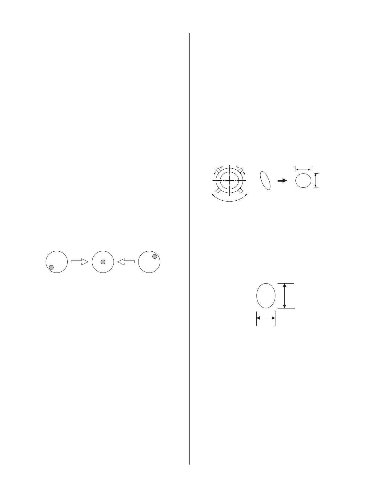
2-8. 4-POLE MAGNET ADJUSTMENT
1. Set the picture mode to PRO and picture to MAX.
2. Receive the Dot signal.
3. Cover the red and blue CRT lenses with lens caps to allow only green
to show (or use the method shown in the note below for turning off the
CRTs individually without using lens caps).
4. Turn the (green) focus VR on the focus block to the right (clockwise)
and set it to under-focus to reduce the spot.
5. Adjust the 4-pole magnet so that the small spot in the center of the
screen becomes round for green and red.
6. Adjust the blue spot to an oval shape X:Y=1:1.2
Note: If lens caps are unavailable, you can cut off the unnecessary color
beams by controlling the service mode 2150P-2 1 RGBS.
Use the center dot
x
y
x : y = 1:1 (Green, Red)
2-9. BLUE DEFOCUS ADJUSTMENT
1. Setup: Apply a Dot Hatch Signal and set the mode to Pro Mode.
Change the color temperature to Cool in the user’s menu.
2. Cover the red and green CRT lenses with lens caps to allow only blue
to show (or use the method shown in the note below for turning off the
CRTs individually without using lens caps).
4. Turn the blue focus VR on the focus block to the right (clockwise) to
make the round dot oval.
D2
2-7. CENTERING MAGNET ADJUSTMENT
Not required - Combined with 2-6 2-Pole And Centering Magnet
Adjustment.
D1
Blue
D1:D2 = 1:1.2
5. Check the ß are with a high luminance signal to make sure the ß are is
minimal while the bright spot is located in the center, If not, readjust
the 2 and 4-pole magnets.
6. Check for uniformity on a 100% IRE to an all white signal.
Note: If lens caps are unavailable, you can cut off the unnecessary color
beams by controlling the service mode 2150P-2 1 RGBS.
— 17 —
KP-51WS500/57WS500/65WS500
2-10. ELECTRICAL ADJUSTMENTS BY REMOTE COMMANDER
All of the circuit adjustments can be made by using the remote
commander (RM-Y909).
NOTE : The following test equipment is required:
1. Pattern Generator (with component outputs)
2. Frequency counter
3. Digital multimeter
4. Audio oscillator
2-10-1.METHOD OF ENTERING THE SERVICE
ADJUSTMENT MODE
SERVICE MODE PROCEDURE
1. TV must be in Standby mode. (Power off)
2. Press “DISPLAY”, “5”, “VOL +”, then “POWER” on the remote
commander.
(Press each button within 1 second of pressing the previous button.)
SERVICE MODE ADJUSTMENT
Data
SERVICE
TV
Category
Adjustment Item
3D-COMB
NRMD
Item NO.
0 0
WSL : XXX
7. If you want to go back to the most recently saved value, press “0”
then “ENTER” to read the memory.
8. Press “MUTING” then “ENTER” to write the new adjustment data into
memory.
9. When you want to exit the service mode, turn the power off.
Note: Press “8” then “ENTER” on the remote commander to restore the
factory settings for user controls and channel memories (this will also
turn set off and then on to exit the service mode).
2-10-2.MEMORY WRITE CONFIRMATION
METHOD
1. After adjustment, turn the power off with the remote commander.
2. Turn the power ON and set to service mode.
3. Cycle through the adjusted items again and confi rm that the
adjustments were saved.
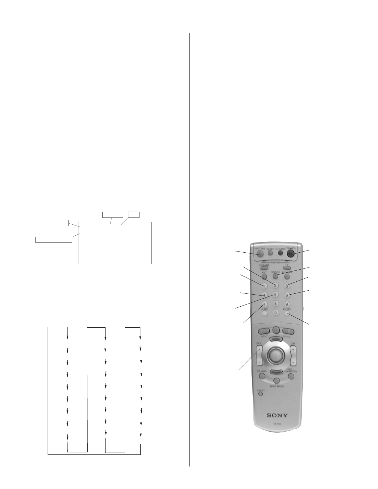
2-10-3.ADJUSTING BUTTONS AND
INDICATOR
Note: When the PJE mode (which displays an internally generated
signal) is activated, several buttons on the remote commander will have
different functions than the ones listed below. Therefore, when in the PJE
mode, refer to section 2-12-3 for button functions.
F / A FLAG : XXXXXXXX
CBA FLAG : XXXXXXXX
3. The screen displays the item being adjusted within that category.
4. Press 1 or 4 on the remote commander to select the adjustment item.
5. Press 3 or 6 on the remote commander to change the data.
6. Press 2 or 5 on the remote commander to select the adjustment
category.
Every time you press 2 (Category up), service mode changes in the
order shown below:
3D-COMB
2103-1
2103-2
2150P-1
2150P-2
2150P-3
2150P-4
2150D-1
2150D-2
2150D-3
2151
AP
TRUS
DLBY
MID1
MID2
MID3
MID5
OSD
SNNR
ID-1
CCD
PJE
OP
ID
MUTING
Category up
Adjustment
item up
Adjustment
item down
Category
down
VOLUME +
POWER
DISPLAY
Data Up
Data Down
ENTER
RM-Y909
— 18 —
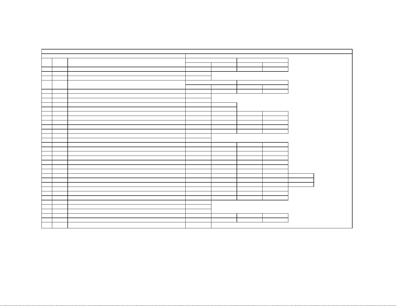
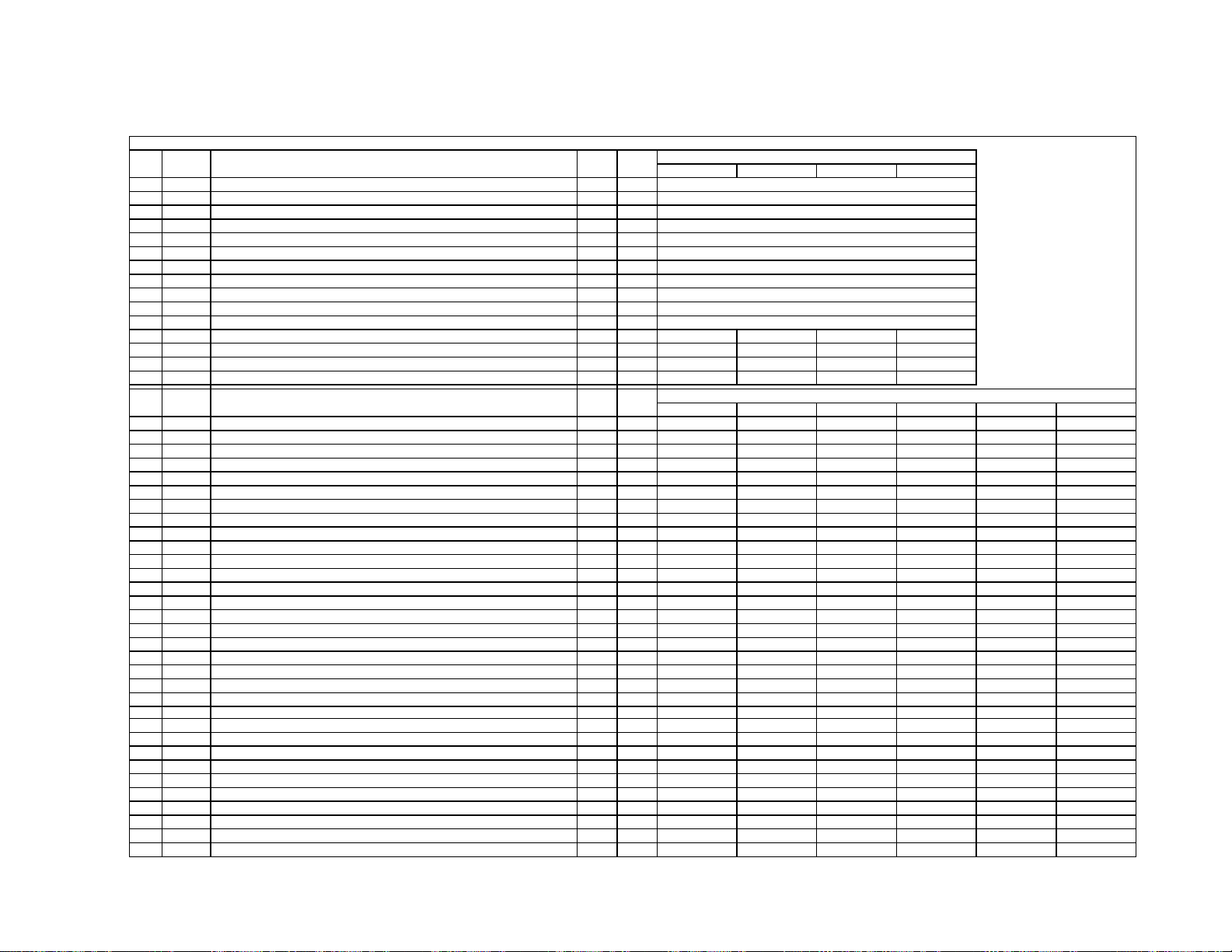
SERVICE DATA LISTS 2-11
e
yby
g
y
t
y
g
g
g
l
f
w
7
11. APPENDIX
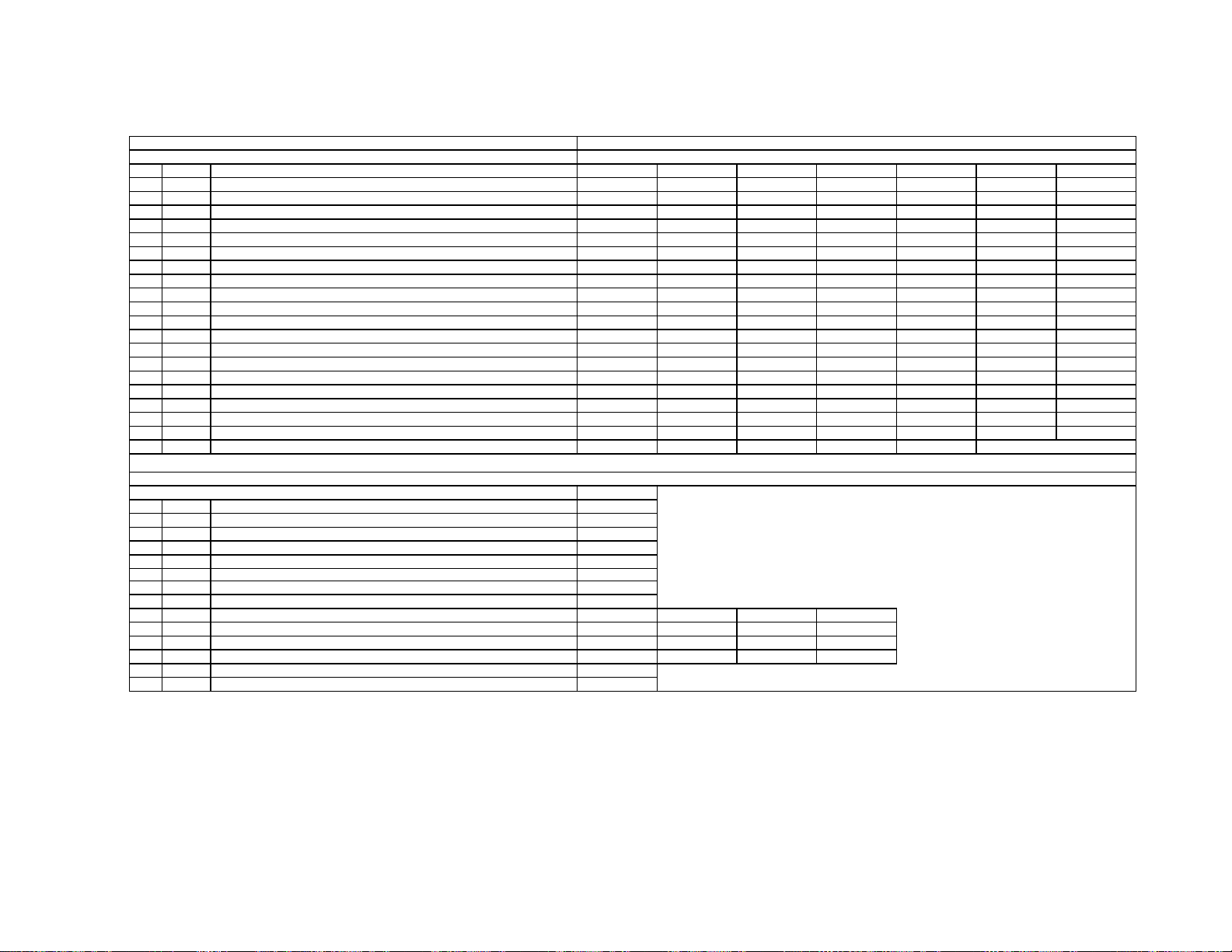
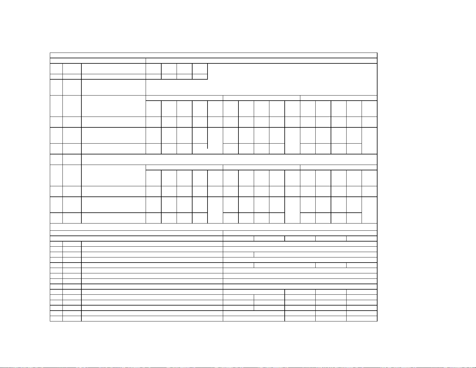
3D-COMB uPD64082
Reg.No &Nam
0 NRMD
1 YAPS
2 CLKS
3 NSDS
4 MSS
5 KILS
6 CDL
7 DYCO
8 DYGA
9 DCCO
10 DCGA
11
YNRL
12
CNRL
13 VTRH
14 VTRR
15 LDSR
16
VAPG
17 VAPI
18 YPET
19 YPFG
20
YHCO
21 YHCG directl
22
HSSL
23 VSSL
24 ADCL
25 D2GA
26 KILR
Operation mode settin
Y-output correction
System clock setting
Selection for standard/non-standard signal processin
Selection for inter-frame/inter-line processin
Killer processing selection
C-signal phase with respect to the Y-signa
DY detection coring level
DY detection gain
DC detection coring level
DC detection gain
Frame recursive YNR nonlinear filter limit level
Frame recursive CNR nonlinear filter limit level
Hysteresis for Hsysnc non-standard signal detection
Sensitivity for Hsysnc non-standard signal detection
Sensitivity for frame non-standard signal detection
V-aperture compensation gain
V-aperture compensation convergence poin
Y peaking filter center frequenc
Y peaking filter gain
Y output high frequency component corin
Y output high frequency component coring gain
Hsync slice level
Vsync slice level
ADC clock dela
Moving detection gain
Killer detection reference
FUNCTION
RF/Video1-4
0
3
1
RF/Video1-4 Svideo
Standard Standard Non-standard
0
0
1
RF
3
NRMD=0 NRMD=1
2
10
5
5
1(
1
1
1
2
VM=of
0
0
3
8
SNNR=0
0
1
12
8
3
NRMD=0 NRMD=1
4
3
1
Non-standard
0
Video1-4
3
2
10
5
5
Video1-4RF
1
1
2
VM=Lo
0
0
SNNR=0
0
0
SNNR=1
1
1
4
Video5,6,
Svideo
33
NRMD=2
2
10
5
5
1
1
2
VM=Mid VM=High
0
0
SNNR=1
0
1
SNNR=2
1
1
NRMD=2
4
Non-standardStandard Non-standard Standard
00
NRMD=3
2
10
5
5
0
0
SNNR=2
0
2
SNNR=3
1
1
NRMD=3
4
SNNR=3
Note: YHCO & YHCG are defined
KP-51WS500/57WS500/65WS500
0
3
SNNR data.
— 19 —
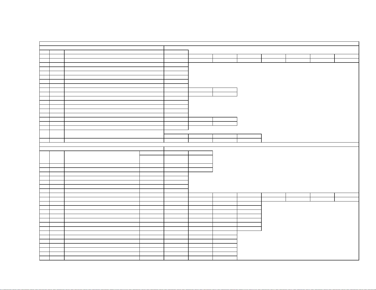
SERVICE DATA LISTS
g
e
g
e
V
V
Y
o
r
g
f
f
f
f
g
f
e
t
r
e
t
g
s
g
f
r
r
.
6
7
7
t
t
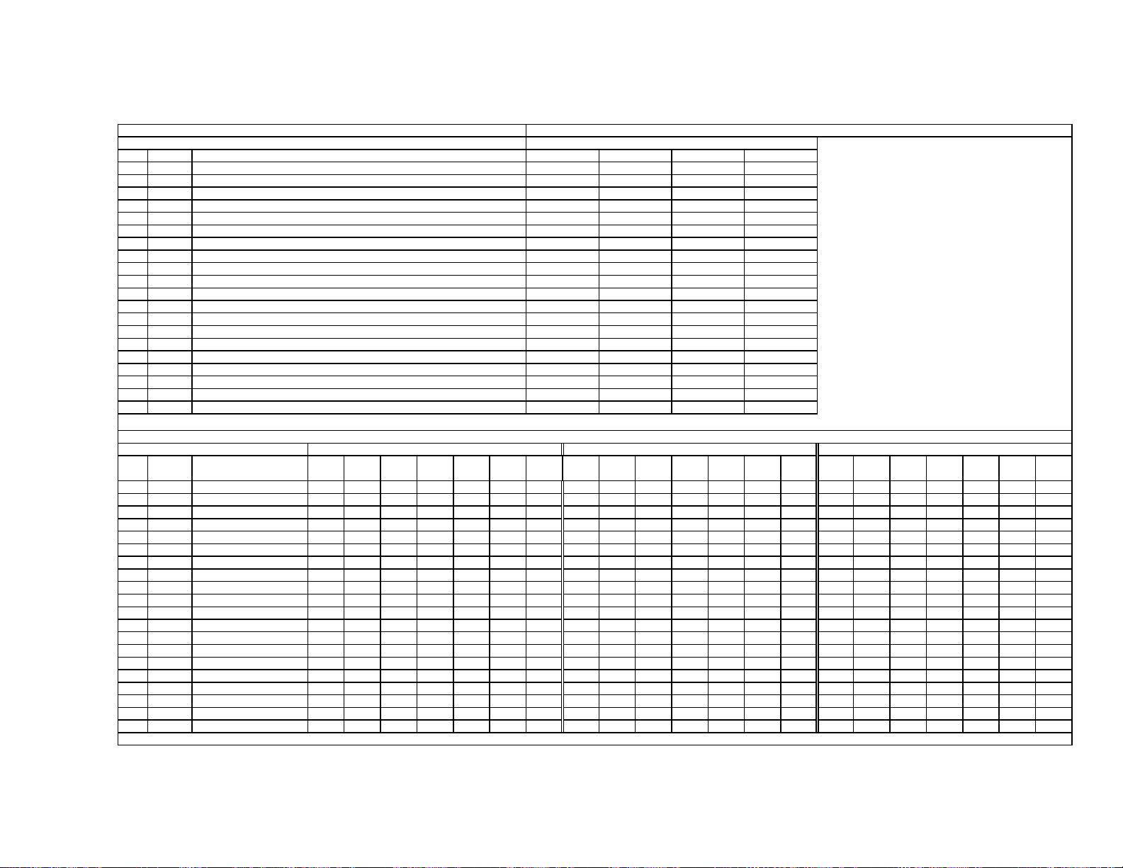
3D-COMB uPD64082
.No &Nam
Re
27
OP
28
NR1
29
NR2
30 WSL
31 HPLL
32 BPLL
33 FSCF
34
PLLF
35 CC3N
36 HDP
37
BGPS
38 BGPW
39 TEST
40 WSC
41 LIND
42 PFGO
Option:Selection of comb filter&recursive n.reduction types
Noise reduction on/off 0
SNNR control on/of
Noise level detection level data
H-PLL filte
Burst PLL filte
Burst extraction gain
PLL loop gain
Selection if a line-comb filter C separation filter characteristic
Fine adjustment of the system H-phase
Internal burst gate start position
Test bit * forbidden settin
Amount of noise detection corin
DRC-M line-doubling setting for non-standard signal
FUNCTION
* Not used
RF
RF
RF
10
KP-51WS500/57WS500/65WS500
1
0
0
1
1
0
1
0
5
4
0
1
0
3
CVideo1 SVideo1
0
Read data
Video1-4
0
Video1-4
0
1
Video5,6,
0
Video5,6,
2
CVideo2 SVideo2
CVideo3
0
SVideo3
10
CVideo4
01
#16 VAPG
NTSC-YCT CXA2103-1
Re
.No &Nam
0
YLE
1 CLE
2 SCON
3 SCOL
4
SHUE
5 YDL
6 SHAP
7 SHF0
8
PREO
9 BPF0
10 BPFO
11 BPSW
12
TRAP
13
LPF
14
AFCG
15
CDMD
16 SSMD
17
HMSK
18
HALI
19
PPHA
Y-Out gain
Cb&Cr-Out gain
Sub contras
Sub colo
Sub hu
Y/C delay tim
Sharpness
Sharpness f0 selector
Sharpness pre/over-shoot ratio
Chroma band filter f0 settin
Chroma band filter O setting
Chroma band filter on/of
Y block chroma trap filter on/of
Y Cb Cr-Output LPF on/of
AFC Loop gain
V countdown system mode selecto
H&Vsync slide level settin
Masking of macrovision signal on/of
H automatic adjustment on/of
H TIM phase adjustment vide
FUNCTION
SNNR=0
0
RF/Video1-4
P&P Lef
-DRC
34
27
RF
0
RF
5
3
3
3
0
1
0
1
RF
1
3
0
1
00
7
Video5,6-480i Video7-480i
P&P Lef
-DRC
40
46
Video1-4
0
Video1-4
4
3
0
0
3
0
0
1
Video1-4
0
3
0
1
SNNR=1
0
P&P Lef
-DRC
40
46
Svideo
4
3
0
0
3
0
0
1
Video5,
0
3
0
1
0
7
SNNR=2
00
Video 5,6-480i
4
3
0
0
3
0
0
1
Video7
0
3
0
0
0
77
SNNR=3
Video7-480i
0
SNNR=1SNNR=0
0
3
0
3
0
0
1
SNNR=2
281
SNNR=3
3
— 20 —
SERVICE DATA LISTS
7
7
7
7
t
g
e
g
g
V
V
Y
g
e
t
g
f
f
o
e
e
t
r
t
t
t
e
t
e
e
i
t
g
f
f
f
e
t
e
r
t
i
t
t
e
e
t
t
t
NTSC-YCT CXA2103-1
20 CBOF Note: CBOF adjustment does not affect Video
21
CROF
22 CBO2 Note: CB02 adjustment onlyaffects Video
23
CRO2
24 ATPD Auto-pedestal Inflection Poin
25
DCTR
NTSC-YCT CXA2103-2
.No &Nam
Re
0
YLE
1 CLE
2 SCON
3 SCOL
4
SHUE
5 YDL
6 SHAP
7 SHF0
8
PREO
9 BPF0
10 BPFO
11 BPSW
12
TRAP
13
LPF
14
AFCG
15
CDMD
16 SSMD
17
HMSK
18
HALI
19
PPHA
20 CBOF
21 CROF
22 ATPD
23
DCTR
Cb Offset Adjustmen
Cr Offset Adjustmen
Cb Offset Adjustmen
Cr Offset Adjustmen
Single Pictur
00
DC Transmission Ratio
FUNCTION
Y-Out gain
Cb&Cr-Out gain
Sub contras
Sub colo
Sub hu
Y/C delay tim
Sharpness
Sharpness f0 selector
Sharpness pre/over-shoot ratio
Chroma band filter f0 settin
Chroma band filter O setting
Chroma band filter on/of
Y block chroma trap filter on/of
Y Cb Cr-Output LPF on/of
AFC Loop gain
V countdown system mode selecto
H&Vsync slide level settin
Masking of macrovision signal on/of
H automatic adjustment on/of
H TIM phase adjustment vide
Cb Offset Adjustmen
Cr Offset Adjustmen
Auto-pedestal Inflection Point P&P & Favorit
DC Transmission Ratio P&P & Favorit
0
RF/Video1-4
P&P Lef
-DRC
0
0
UBLK-0
0
Single Pictur
0
0
Video5,6-480i
P&P Lef
-DRC
0
0
P&P & Favorit
0
0
RF/Video1-4
P&P Righ
34
27
RF
0
RF Cvideo
4
3
0
0
0
0
00
RF
1
3
0
1
0
7
RF/Video1-4
P&P Righ
UBLK-0
0
0
Video7-480i
P&P Lef
-DRC
34
32
2
1
Video5,6,7-480
P&P Righ
, DRC
38
31
Video1-4
0
3
0
00
0
0
Video1-4
0
3
0
1
0
7
Video5,6,7-480
P&P Righ
, DRC
P&P & Favorit
UBLK-1
0
0
Note: CROF adjustment does not affect Video
Note: CR02 adjustment onlyaffects Video
UBLK-3 UBLK-4UBLK-1 UBLK-2 UBLK-5 UBLK-6
0
0
Note: Data in the ri
Note: Sub si
Svideo
4
3
0
0
0
00
0
0
Note: Re
Note: Reg.No 22 and 23 are the same data as CXA2103-1.
.No 14 to 19 are the same data as CXA2103-1.
UBLK-2
2
1
02
0
ht column is used when main signal is NOT 480i
nalgoes through DRC, when main signal is 480p, 1080i, or 720p
SNNR=0
0
UBLK-3
0
2
SNNR=1
13
0
0
P&P & Favorit
SNNR=2
UBLK-5UBLK-4
KP-51WS500/57WS500/65WS500
2
24
P&P & Favorit
2
2
UBLK-7
23
3
SNNR=3
3
2
UBLK-7UBLK-6
2
30
— 21 —
SERVICE DATA LISTS
g
e
T
V
V
V
T
T
T
e
e
K
)
)
)
)
)
)
)
)
)
)
)
)
)
)
)
)
)
)
)
)
)
)
)
)
)
)
)
)
p
i
P
P
)
i
Y
r
T
t
e
e
e
f
f
f
L
f
f
f
s
g
o
c
)
)
)
)
)
)
)
)
)
)
)
)
)
.No &Nam
Re
0
SBOT
1 YOF
2 CBOF
3
CROF
4
SBRT
5 RDRV
6 GDRV
7 BDRV
8
RCUT
9 GCUT
10 BCUT
11
WBSW WB_S
12
SBOF
13 RDOF Offset for RDR
14 GDOF Offset for GDR
15 BDOF Offset for BDR
16 RCOF Offset for RCU
17 GCOF Offset for GCU
18
BCOF
CRT Driver CXA2150P-2 settings for Vivid mod
Reg.No &Nam
0
ALB
1
RGBS
2 BLKB
3 LIML
4 PABL
5 SABL
6 AGNG
7 AKBO
8 SYPH
9 CLPH
10
CLGA
11 JAXS
12 BLKO
FUNCTION
Offset for SBR
DC-offset for
DC-offset for Cb
DC-offset for C
Sub Brigh
R output driv
G output driv
B output driv
R output cutof
G output cutof
B output cutof
Offset for SBR
Offset for BCU
FUNCTION
PIC_ON:RGB output including AKB reference pulse on/of
R_ON/G_ON/B_ON : R/G/B outputs on/of
BLK_BTM:RGB output bottom limit level
PLIMIT_LEV:Threshold level for excessively high input
P_ABL:DC-level in RGB output detection for PEAK AB
S_ABL:S ABL gain
AGING_W/AGING_B:AGING_W/AGING_B modes on/of
AKBOFF:Automatic/Manual =Cut off settin
SYNC_PHASE:Hsync delay with respect to Vide
CLP_PHASE:Internal clamp pulse phase
CLP_GATE:Switch for the gated internal clamp pulse with Hsyn
JAXIS:color axis switch
BLKO:Blanking switch
RF
0
0
35 35
31
31
Vivid Std
63
63 (no memory
64
63 (no memory
63
63 (no memory
63 (no memory
69
63 (no memory
63
63
63 (no memory
65
63 (no memory
51WS500
Svideo
0
0
35
363636
Movie
63
67
63
56
63
63
61
Video5,6 480i
5
37
Pro
63 (no memory
63 (no memory
63 (no memory
63 (no memory
63 (no memory
63 (no memory
63 (no memory
RF/Video1-4 Video5,6 480i Video5,6 480
Video5,6 480
40
4139
Vivid Movie
0 (no memory) 0 (no memory) 0 (no memory) 0 (no memory)
63 63 (no memory
65 63 (no memory
63 63 (no memory
69 63 (no memory
63 63 (no memory
63 63 (no memory
66 63 (no memory
1
7
3
0
15
0
0
0
0
3
0
0
0
Cvideo
0
00
0 (no memory) 0 (no memory)0 (no memory) 0 (no memory)
0
Video5,6 1080
7
0
31
31
Std
0
3
0
KP-51WS500/57WS500/65WS500
P&P
7
0
36
57WS500 65WS500
63
67 63 (no memory
63
56 63 (no memory
64 63 (no memory
63 63 (no memory
62 63 (no memory
Video5,6 1080
0
3
0
7
7
49
49
Pro
63 (no memory
63 (no memory
0
3
0
Video7 480iVideo7 vga
5
3235
31
Vivid
0 (no memory) 0 (no memory) 0 (no memory) 0 (no memory)
63 63 (no memory
65 63 (no memory
63 63 (no memory
70 63 (no memory
63 63 (no memory
63 63 (no memory
65 63 (no memory
P&P
0
3
0
Video7 480
50
7
49
49
Std Movie Pro
Video7 1080i
157
7
49
49
63 63 (no memory
67 63 (no memory
63 63 (no memory
56 63 (no memory
64 63 (no memory
63 63 (no memory
61 63 (no memory
— 22 —
SERVICE DATA LISTS
g
e
V
V
V
V
e
e
K
c
2
g
o
g
t
T
o
0
t
e
4
0
0
g
P
i
P
CRT Driver CXA2150P-3
.No &Nam
Re
0
SYSM
1
UVML
2 VMMO
3 VMCR
4 VMLM
5 VMF0
6 VMDL
7 SHOF
8 SHF0
9
PRO
10
F1L
11
CDSP
12 LTL
13 LTMD
14 CTL
15 CTMD
16 UBOF
17 UCOF
18 UHOF
19
MIDE
CRT Driver CXA2150P-2 Video7 Settings for Vivid Mod
Reg.No &Nam
0
ALB
1
RGBS
2 BLKB
3 LIML
4 PABL
5 SABL
6 AGNG
7 AKBO
8 SYPH
9 CLPH
10
CLGA
11 JAXS
12 BLKO
SYSTEM:Signal bandwidth settin
VM_LEV:VM_OUT level
System Micro pin#4
VM_COR:VM_OUT coring level
VM_LMT:VM_OUT limit level
VM F0: VM f0
VM_DLY:VM_OUT phas
Offset for USHP=SHOF x
SHP_F0:Sharpness circuit f
PRE/OVER:Y signal pre/over-shoot rati
SHP_F1:Sharpness for higher f
SHP_CD:Sharpness in part of high color saturation
LTI_LEV:Luminance transient improvemen
LTI_MODE:LTI mode settin
CTI_LEV:Chrominance transient improvemen
CTI_MODE:CTI mode setting
Offset for UBR
Offset for UCOL=UCOF x
Offset for UHUE
MID enhancement settin
SYNC_PHASE:Hsync delay with respect to Vide
CLP_PHASE:Internal clamp pulse phase
CLP_GATE:Switch for the gated internal clamp pulse with Hsyn
FUNCTION
FUNCTION
Vivid
RF
1
3
1
0
3
2
1
0
1
0
0
3
3
1
0
0
0
3
0
3
-
-
-
-
-
-
-
-
Video7 VGA Video7 480i Video7 480
000
33
0000
-
-
Cvideo Svideo
1
3
1
0
3
2
2
1
1
0
0
3
3
1
0
0
0
3
0
15
1
3
1
0
3
2
2
1
1
0
0
3
3
1
0
0
0
3
0
15
3
Video5,6 480i Video5,6 480
1
2
1
1
3
2
2
2
1
3
0
3
3
1
0
0
0
3
0
7
Video7 1080i
0
3
11
KP-51WS500/57WS500/65WS500
1
2
1
1
3
2
2
3
1
3
1
3
3
0
0
0
7
3
0
2
3
1
3
3
2
0
3
0
3
3
3
3
0
0
0
9
0
0
P&PVideo5,6 1080
2
3
0
3
3
2
1
3
1
3
3
3
3
1
0
0
7
2
0
— 23 —
SERVICE DATA LISTS
s
e
V
V
V
V
o
e
V
V
V
V
ge
t
T
2
g
0
t
g
e
4
0
o
0
g
p
CRT Driver CXA2150P-3 DVI Setting
Reg.No &Nam
0
SYSM
1
UVML
2 VMMO
3 VMCR
4 VMLM
5 VMF0
6 VMDL
7 SHOF
8 SHF0
9
PRO
10
F1L
11
CDSP
12 LTL
13 LTMD
14 CTL
15 CTMD
16 UBOF
17 UCOF
18 UHOF
19
MIDE
SYSTEM:Signal bandwidth settin
VM_LEV:VM_OUT level
System Micro pin#4
VM_COR:VM_OUT coring level
VM_LMT:VM_OUT limit level
VM F0: VM f0
VM_DLY:VM_OUT phas
Offset for USHP=SHOF x
SHP_F0:Sharpness circuit f
PRE/OVER:Y signal pre/over-shoot rati
SHP_F1:Sharpness for higher f
SHP_CD:Sharpness in part of high color saturation
LTI_LEV:Luminance transient improvemen
LTI_MODE:LTI mode settin
CTI_LEV:Chrominance transient improvemen
CTI_MODE:CTI mode setting
Offset for UBR
Offset for UCOL=UCOF x
Offset for UHUE
MID enhancement settin
FUNCTION
KP-51WS500/57WS500/65WS500
Video7 VGA Video7 480i Video7 480
2113
2223
1111
0000
3333
0110
2112
0223
1111
3333
0000
3333
0333
1001
0
0000
222
01
0
80
Vivid
003
00
00
711
Video7 1080i
2
0
CRT Driver CXA2150P-3 settings for standard, movie and pr
Reg.No &Nam
#0
SYSM
#1
UVML
#2 VMMO 111111100000000000000
#3 VMCR 100113311111333333333
#4 VMLM 333333333333333333333
#5 VMF0 222222222222222222222
#6 VMDL 022221112222112222211
#7 SHOF 100023311111110000000
#8 SHF0 111111111111111111111
#9
PRO
#10
F1L
#11
CDSP
#12 LTL
#13 LTMD 111110111111011111101
#14 CTL
#15 CTMD 000000000000000000000
#16 UBOF 777779777777777777777
#17 UCOF 111110000000000000000
#18 UHOF 000000000000000000000
#19
MIDE
RF CV SVV5,6 V5,6 V5,6 P&P RF CV SVV5,6 V5,6 V5,6 P&P RF CV SVV5,6 V5,6 V5,6 P&P
480i 480P 1080i 480i 480P 1080i 480i 480P 1080i
111112211111221111122
222222311111110000000
030000033332233332322
000013300012330001233
333333300000000000000
222222200000000000000
000000000000000000000
2 14 14 6 10 -- -- 1 13 13 5 9 -- -- 0 12 12 4 8 -- --
MovieStandard
NVM ADDRESS: see the next pa
Pro
— 24 —
SERVICE DATA LISTS
g
e
V
V
V
o
e
p
V
V
V
V
ge
g
e
V
V
V
CRT Driver CXA2150P-3
.No &Nam
Re
#1
UVML
#3 VMCR
#10
F1L
#11
CDSP
#12 LTL
#14 CTL
#19
MIDE
FUNCTION
SNNR=0 SNNR=1 SNNR=2 SNNR=3
0
0
0
0
0
0
0
0
+1
-1
0
0
0
0
0
+2
-2
0
0
0
0
0
+3
-3
0
0
0
0
KP-51WS500/57WS500/65WS500
CRT Driver CXA2150P-3 Video7 settings for standard, movie and pr
Reg.No &Nam
#0
SYSM
#1
UVML
#2 VMMO 111110001000
#3 VMCR 000000000000
#4 VMLM 333333333333
#5 VMF0 011001100000
#6 VMDL 211221122222
#7 SHOF 033301110002
#8 SHF0 111111111111
#9
PRO
#10
F1L
#11
CDSP
#12 LTL
#13 LTMD 110111111111
#14 CTL
#15 CTMD 000000000000
#16 UBOF 244422222222
#17 UCOF 000000000000
#18 UHOF 000000000000
#19
MIDE
CRT Driver CXA2150P-3
.No &Nam
Re
#1
UVML
#3 VMCR
#10
F1L
#11
CDSP
#12 LTL
#14 CTL
#19
MIDE
FUNCTION
Video7 Video7 Video7 Video7 Video7 Video7 Video7 Video7 Video7 Video7 Video7 Video7
VGA 480i 480
Standard Movie
211321132223
222221112000
333333333333
000000000000
333300000000
023301220000
000300020000
8610085908480
SNNR=0 SNNR=1 SNNR=2
0
0
0
0
0
0
0
1080i VGA 480i 480p1080i VGA 480i 480p1080i
NVM ADDRESS: see the next pa
SNNR=3
0
+3
-3
0
0
0
0
+1
0
-1
0
0
0
0
0
+2
-2
0
0
0
0
Pro
— 25 —
SERVICE DATA LISTS
g
e
K
K
y
.
e
d
e
l
T
T
L
r
s
p
p
i
i
i
P
P
}
i
P
P
p
p
CRT Driver CXA2150P-4
.No &Nam
Re
0 UPIC
1 UBRT
2
3
4 USHP
5 UTMP
6
UCOL
UHUE
UDCL
PICTURE:Picture
BRIGHT:Brightness
COLOR:Colo
HUE:Hue
SHARPNESS:Sharpnes
Color Temperature
DCOL:Dynamic color setting
FUNCTION
Vivid
63
26
31
31
32
2
2
Standard
44
31
31
31
40
1
2
Movie
31
31
31
31
31
0
KP-51WS500/57WS500/65WS500
Pro
31
31
31
31
31
1
00
RF/Video1-4
7 AXIS
8 UGAM
9 AGAM ---
10 GSBO
11 GCOO
12 GHUO
13 UBL
14 ABL
15 DCTR
16 DPIC
17 DSBO
18 ABLM
19 ABLT
20 EPOF
21 SPOF << Onl
22 SCON
23 CLOF
24 HUOF
25 IDSW
26 DATA
COL_AXIS:color matrix setting
GAMMA_L:RGB output GAMMA correction
GAMMA_L---Void Data
Offset for SBR
Offset for UCO
Offset for UHUE
Initial Black Level
--- Void Data
DC_TRAN:Y signal DC transmission
DPIC_LEV:Y signal AUTO PEDESTAL level
Offset for SBR
ABL MODE:ABL mod
ABL_TH:ABL current detection Vth contro
Offset for UPIC=EPOF x - void Data
Offset for UPIC=SPOF x - Not use
SUB_CONTRAST:SUB PICTURE
Offset for UCOL
Offset for UHUE
Not used
Display of vertical compression modes. Not us
0
RF/Video1-4
UGAM-0
0
00
0
RF/Video1-4
6
--UBLK0
1
0
7
0
Full
0
{A6 E9 1F
15
RF/Video1-4
8
8
4
0
Video5,6 480i
Video5,6 480i
UGAM-1
Video5,6 480i
UBLK1
Video5,6 480i
Video5,6 480
0
4
0
0
6
1
1
7
0
available at Vcomp1&2
5
8
4
0
Video5,6 480
4
UGAM-2
0
0
0
Video5,6 480
6
UBLK2
1
2
7
0
Video5,6 480
5
8
4
Video5,6 1080
0
Video5,6 1080
15
UGAM-3
0
0
Video5,6 1080
6
23
11
7
0
Video5,6 1080
4
8
4
P&P
Picture Mode Vivid
P&P
5
UGAM-4
0
0
00
Picture Mode Vivid
P&P
4
UBLK4UBLK3
3
1
7
0
P&P
4
8
4
Video7 vga
Video7 vga Video7 480i Video7 480
0
UGAM-5
0
0
0
Video7 vga Video7 480i Video7 480
06
UBLK5
2
77
Video7 vga Video7 480i Video7 480
5554
88
4444
Video7 480i
00
4
UGAM-6
0
0
0
6
UBLK6
7
1
Video7 480
00
4
UGAM-7
0
0
0
UBLK7
32
2
10
88
Video7 1080i
Video7 1080i
Video7 1080i
Video7 1080i
0
1
6
— 26 —
SERVICE DATA LISTS
g
e
K
K
g
e
y
y
d
o
t
t
e
T
y
t
t
s
o
o
d
e
d
e
CRT Driver CXA2150P-4
.No &Nam
Re
#4
USHP
SHARPNESS:Sharpnes
FUNCTION
KP-51WS500/57WS500/65WS500
SNNR SNNR SNNR SNNR
=0 =1 =2 =3
0134
Picture Mode : Standar
RF V5,6 V5,6 V5,6 P&P RF V5,6 V5,6 V5,6 P&P RF V5,6 V5,6 V5,6 P&P
& 480i 480P 1080i & 480i 480P 1080i & 480i 480P 1080i
#8 UGAM 222110000000000
#8 UGAM 0221 0000 0000
DVI
#13
UBL
#13
UBL
DVI
CRT Driver CXA2150D-1
.No &Nam
Re
0 VPOS
1 VSIZ
2 VSZO
3 VLIN
4 VSCO
5 VCEN
6 VPIN
7 NSCO
8 HTPZ
9 ZOOM
10 APSW
11 ASPT
12 SCRL
13 UVLN
14 LVLN
GAMMA_L:RGB outpu
GAMMA correction
GAMMA_L:RGB outpu
GAMMA correction
Initial Black Level
Initial Black Level
FUNCTION
V_POSITION:Vertical position
V_SIZE:Vertical siz
V_SIZE OFFSE
V_LINEARITY:Vertical linearit
S_CORRECTION:Vertical S-correction
VSAW0 DCH/VSAW0 DCL:Vertical center adjustmen
VSAW0_AMP:Vertical PIN adjustmen
VSAW1_DC:Rotation
VSAW1_AMP:Horizontal trapezoi
ZOOM_SW:Zoom switch
ASP_SW:Aspect switch
V_ASPECT:Aspect rati
V_SCROLL:Vertical scroll
UP_VLIN:Upper vertical linearit
LO_VLIN:lower vertical linearit
V1-4 V1-4 V1-4
A6 22 07 A6 23 07 A6 24 07 A6 25 07 A6 26 07 A6 27 07 A6 28 07 A6 29 07 A6 2A 07 A6 2B 07 A6 2C 07 A6 2D 07 A6 2E 07 A6 2F 07 A6 30 07
Video7 Video7 Video7 Video7 Video7 Video7 Video7 Video7 Video7 Video7 Video7 Video7
VGA 480i 480P 1080i VGA 480i 480P 1080i VGA 480i 480P 1080i
A6 35 07 A6 36 07 A6 37 07 A6 38 07 A6 39 07 A6 3A 07 A6 3B 07 A6 3C 07 A6 3D 07 A6 3E 07 A6 3F 07 A6 40 07
Picture Mode : Standar
RF V5,6 V5,6 V5,6 P&P RF V5,6 V5,6 V5,6 P&P RF V5,6 V5,6 V5,6 P&P
& 480i 480P 1080i & 480i 480P 1080i & 480i 480P 1080i
V1-4 V1-4 V1-4
333331111100000
A6 22 38 A6 23 38 A6 24 38 A6 25 38 A6 26 38 A6 27 38 A6 28 38 A6 29 38 A6 2A 38 A6 2B 38 A6 2C 38 A6 2D 38 A6 2E 38 A6 2F 38 A6 30 38
Video7 Video7 Video7 Video7 Video7 Video7 Video7 Video7 Video7 Video7 Video7 Video7
VGA 480i 480P 1080i VGA 480i 480P 1080i VGA 480i 480P 1080i
0333 0111 0000
A6 35 38 A6 36 38 A6 37 38 A6 38 38 A6 39 38 A6 3A 38 A6 3B 38 A6 3C 38 A6 3D 38 A6 3E 38 A6 3F 38 A6 40 38
Picture Mode : Movi
Picture Mode : Movi
1080i FULL
9
00
0
29 29
0
00
0
NORMAL
7
9
31
15
7
15
0
29
0
0500
Picture Mode : Pr
Picture Mode : Pr
ZOOM
0
9
1
0
44
29
WIDE ZOOM
9
1
0
220
29
50
— 27 —
SERVICE DATA LISTS
g
e
g
e
K
K
K
K
K
K
t
y
h
h
g
g
e
y
e
e
t
e
r
g
w
w
d
h
CRT Driver CXA2150D-2
.No &Nam
Re
0 HCNT
1 HPOS
2 HSIZ
3 SLIN
4 MPIN
5 PIN
6 PIN0
7 UCP
8 LCP
9 UXCG
10 LXCG
11 UXCP
12 LXCP
13 XCPP
14 PPHA
15 VANG
16 LANG
17 VBOW
18 LBOW
19 CPY1
HC_PARA_DC:Horizontal cente
H_POSITION:Horizontal position
H_SIZE:Horizontal siz
MP_PARA_DC:Horizontal S-correction
MP_PARA_AMP:Horizontal middle pin
PIN_AMP:Horizontal pin
PIN AMP offse
UP_CPIN:Upper corner pin
LO_CPIN:Lower corner pin
UP_UCG:Upper extra corner pin gain
LO_UCG:Lower extra corner pin gain
UP_UCP:Upper extra corner pin position
LO_UCP:Lower extra corner pin position
UC_POL:Extra corner pin polarit
PIN_PHASE:Pin phas
AFC_ANGLE:AFC angl
HC_PARA_PHASE:Linearity angl
AFC_BOW:AFC bo
HC_PARA_AMP:Linearity bo
Copy function 1: * Not use
FUNCTION
1080i ZOOM
7
FULL/NORM WIDE ZOOM
19
25
0
10
7
31
31
0
0
2
2
0
31
31
33
31
48
0
KP-51WS500/57WS500/65WS500
0
10
77
31
31
0
0
2
2
0
CRT Driver CXA2150D-3
Re
.No &Nam
0 HBL
1 LBL
2 RBL
3 VBL
4 TBL
5 BBL
6 VCMP
7 HCMP
8 ACMP
9 PCMP
10 AFCM
11 VFRQ
12 VON
13 JUMP
14 VDJP
15 VDST
16 EWDC
17 AKBT
HBLK_SW:Horizontal blanking switc
LEFT_BLK:Left blanking
RIGHT_BLK:Right blankin
VBLK_SW:Vertical blanking switc
UP_BLK:Top blankin
LO_BLK:Bottom blankin
V_COMP:Vertical compensation
H_COMP:Horizontal compensation
AFC_COMP:AFC compensation
PIN_COMP:Pin compensation
AFC_MODE:AFC compensation
V_FREQ:Vertical frequenc
V_ON:Vertical drive on
JMP_SW:Reference pulse jump switc
VDRV_SW:Vertical drive switch
RST_SW:Vertical drive start switch
EW_DC:Pin DC level shif
AKBTIM:AKB timing
FUNCTION
1080i
56
25
4
515
0
2
1
0
9
Full
1
15
0
0
0
0
1
0
— 28 —
NORMAL
1
1
15
15
0
0
0
0
1
1
0
1
0
0
99
58
23
Zoom
0
15
15
0
0
0
3
1
0
9
WideZoom
0
15
15
0
0
0
00
1
0
9
SERVICE DATA LISTS
g
e
S
e
g
e
6
e
Y
f
z
i
z
z
z
z
z
P
P
z
r
t
l
L
e
r
e
6
L
s
e
e
z
Component I/F & Sync Separation CXA2171
.No &Nam
Re
0 MTRX
1 GAIN
2 CBGN
3 VTC
4 HWID
5 HSEP
6 TEST
7 FRGB
8 HMSK
Audio Processor BH3868F
Reg.No &Nam
0 SVOL
1 SBAL
2 SBAS
3 STRE
4 BBLP
5 BBHP
6 SREF
7 AGC
8 BBE
MAT_OUT
GAIN_SE
CBGAIN
V_TC
H_WIDTH
HSEP_SE
TEST
No used
Hsync masking in vertical retrac
Volume:Offset for Volum
Balance Offset for Balanc
Bass:Offset for Bas
Treble:Offset for Trebl
BBE low pass filte
BBE high pass filte
Surround effec
Auto gain contro
BBE on/of
FUNCTION
FUNCTION
Video5,6 480i
15.75kh
0
0
9
1
1
Video5,
1
0
0
V5,6,7 1080i
0
Video5,6 480P
31.50kh
0
Video7
1
ELSE
1
0
7
10
7
0
2
11
0
0
Video5,6 1080
33.75kh
Sub
0
45kh
11
KP-51WS500/57WS500/65WS500
Video7 480i Video7 480P Video7 1080iVideo5,6 720
15.75kh
0011
31.50kh
33.75kh
Video7 720
45kh
TruSurround NJM2180
Re
.No &Nam
0 TSMD
1 ATT
DLBY NJW110
Reg.No &Nam
0 DBMD
1 SCH
2 ADSW
3 CECH
4 DEL
5 SSEL
Trusurround effect selection
No used for Wide model
FUNCTION
2
0
FUNCTION
0
0
0
0
7
0
— 29 —
SERVICE DATA LISTS
g
e
y
r
g
e
s
g
s
g
e
g
t
C
e
e
e
e
e
t
e
e
e
e
e
C
x
P
r
r
P
MID-1
.No &Nam
Re
Displa
0 DHPH
1 DVPH
2 DHAR
3 DVAR
4 DHPW
5 DVPW
22 DPSW
23 MDL
Misc. Common Data
6 DYCD
7 DYSD
Favorite / Othe
8 MDHP
10 MDHS
Sin
9 MDVP
11 MDVS
Index / Other
12 MLHP
13 MLVP
Favorite
14 SDHP
15 SDVP
Favorite
16 SDHS
17 SDVS
PinP Position
18 PDHP
19 PDVS
PinP Size
20 PDHS
21 PDVS
Sin
24 BCOL
Data
H active display area phas
V active display area phas
H active display area siz
V active display area siz
display H pulse width
display V pulse width
display PLL switch
model select
display output Y-C delay correction
display output YS signal delay selec
main display picture H position
main display picture H siz
le / Favorit
main display picture V position
main display picture V siz
multi picture mode H position
multi picture mode V position
sub display picture H position
sub display picture V position
sub display picture H siz
sub display picture V siz
le / Other
Backgraund Y level
FUNCTION
110
20
240
135
55
5
1
0
Data
2
1
Normal
154
162
ingle 480i/480
30
120
Inde
36
31
Favorite
166
20
Favorite
44
29
-
-
-
-
Single
5
Favorite
9
149
Single 720
30
120
Others
36
31
Others
5
KP-51WS500/57WS500/65WS500
Others
0
240
Favorite
20
97
MID-2
.No &Nam
Re
MID Mode, Wide mode, Input Si
0 DRHP
1 DRHS
2 DRVP
3 DRVS
DRC H active area position
DRC H active area siz
DRC V active area position
DRC V active area siz
FUNCTION
nal Forma
RF,Video, Y
142
162
37
120
Single
YPbP
141
162
37
120
RF,Video, Y
111
178
37
120
Single
YPbP
110
178
37
120
— 30 —
SERVICE DATA LISTS
g
e
g
t
g
t
t
t
e
e
g
e
e
e
e
e
e
e
e
C
t
x
V
i
C
r
C
r
x
C
e
e
e
r
MID-2 (Continued)
0 DRHP
1 DRHS
2 DRVP
3 DRVS
0 DRHP
1 DRHS
2 DRVP
3 DRVS
MID-3 : INPUT)
Re
.No &Nam
0 VDHP
1 VDHS
2 VDVE
3 VDVS
0 VDHP
1 VDHS
2 VDVE
3 VDVS
0 VDHP
1 VDHS
2 VDVE
3 VDVS
0 VDHP
1 VDHS
2 VDVE
3 VDVS
4 VDVO
5 VCPO
6 VCWD
7 VYCD
8 VSTP
9 VSTT
10 VHSC
DRC H active area position
DRC H active area siz
DRC V active area position
DRC V active area siz
DRC H active area position
DRC H active area siz
DRC V active area position
DRC V active area siz
MID mode, Wide mode, Input Si
VDO H active area position
VDO H active area pixel siz
VDO V active area even position
VDO V active area line siz
VDO H active area position
VDO H active area pixel siz
VDO V active area even position
VDO V active area line siz
VDO H active area position
VDO H active area pixel siz
VDO V active area even position
VDO V active area line siz
VDO H active area position
VDO H active area pixel siz
VDO V active area even position
VDO V active area line siz
Input Si
nal Forma
VDO V active area line siz
VDO V active area odd position
VDO clamp pulse output timin
VDO clamp pulse width
VDO PLL phase ditect stop line coun
VDO PLL phase ditect start line coun
VDO H sync cycle
FUNCTION
nal Forma
Twin, Favorite
RF,Video, Y
132
166
54
112
RF,Video, Y
480P
109
166
37
120
480P
128
155 150
53
112
480P
136
152
57
110
480P
132
154
51 34
113
RF,Video, S-Video, YPbPr 480
0
95
3
0
-
-
130
Inde
139
164
50
114
Single
720P
95
108
24
180
Twin, Favorite
1080i
94
37
126
Memo
1080i
102
147
44
123
Inde
1080i
99
149
128
YPbP
131
166
54
112
YPbP
138
164
50
114
YPbPr No Sig.
205
226
37
56
720P
111
99
50
168
720P
115
98
58
164
720P
112
99
48
169
480P
0
70
3
0
119
4
-
RF,Video, Y
Twin-Righ
RF,Video, Y
YPbPr No Sig.
YPbPr No Sig.
YPbPr No Sig.
Memo
YPbP
142
162
58 58
138
166
54 54
112
179
199
24
56
179
199
24
56
166
187
24
56
1080i
0
40
3
0
160
0
-
141
162
110110
Scroll-Small
RF
143
162
112
Twin-Right
RF,Video, S
197
215
26
56
Index-Small
RF
204
211
26
56
720P
0
40
3
0
146
0
-
KP-51WS500/57WS500/65WS500
— 31 —
SERVICE DATA LISTS
t
t
t
t
t
l
l
l
t
l
l
l
t
l
l
l
l
l
l
t
t
t
t
l
l
l
t
l
l
l
t
l
l
l
l
l
l
g
e
p
o
e
t
MID-5 Enhance Table Data Setting
0 P-OP Table selec
1 MHLY Main H LPF Y Coefficient selec
2 MHLC Main H LPF C Coefficient selec
3 MVLYMain V LPF Y Coefficient selec
4 MVLC Main V LPF C Coefficient selec
5 MHYR Main H Enhance. Y Coreingleve
6 MHYL Main H Enhance. Y Clip leve
7 MHYE Main H Enhance. Y Enhancement leve
8 MHYC Main H Enhance. Y Coefficient selec
9 MHCR Main H Enhance. C Coreingleve
10 MHCL Main H Enhance. C Clip leve
11 MHCE Main H Enhance. C Enhancement leve
12 MHCC Main H Enhance. C Coefficient selec
13 MVYR Main V Enhance. Y Coreingleve
14 MVYL Main V Enhance. Y Clip leve
15 MVYE Main V Enhance. Y Enhancement leve
16 MVCR Main V Enhance. C Coreingleve
17 MVCL Main V Enhance. C Clip leve
18 MVCE Main V Enhance. C Enhancement leve
0 P-OP Table selec
1 MHLY
2 MHLC Main H LPF C Coefficient selec
3 MVLYMain V LPF Y Coefficient selec
4 MVLC Main V LPF C Coefficient selec
5 MHYR Main H Enhance. Y Coreingleve
6 MHYL Main H Enhance. Y Clip leve
7 MHYE Main H Enhance. Y Enhancement leve
8 MHYC Main H Enhance. Y Coefficient selec
9 MHCR Main H Enhance. C Coreingleve
10 MHCL Main H Enhance. C Clip leve
11 MHCE Main H Enhance. C Enhancement leve
12 MHCC Main H Enhance. C Coefficient selec
13 MVYR Main V Enhance. Y Coreingleve
14 MVYL Main V Enhance. Y Clip leve
15 MVYE Main V Enhance. Y Enhancement leve
16 MVCR Main V Enhance. C Coreingleve
17 MVCL Main V Enhance. C Clip leve
18 MVCE Main V Enhance. C Enhancement leve
Main H LPF Y Coefficient selec
KP-51WS500/57WS500/65WS500
0
1
3
0
0
1
1
7
1
0
1
0
1
0
1
0
0
1
0
8
3
0
0
0
1
7
1
0
1
0
1
0
0
0
1
0
RF
12
1
3
0
0
1
1
7
1
0
1
0
1
0
1
0
0
1
0
YPbPr-480
9
00
3
0
0
0
1
7
1
0
1
0
1
0
11
0
0
1
0
1
3
0
0
2
1
3
1
0
1
0
1
22
1
2
0
1
0
10
0
3
0
0
0
1
3
1
0
1
0
1
2
1
2
0
1
0
11
3
1
3
0
0
1
1
3
1
0
1
0
1
0
5
0
1
0
0
3
0
0
1
1
5
1
0
1
0
1
2
1
5
0
1
0
4
1
3
0
0
0
1
3
1
0
1
0
1
0
1
0
0
1
0
12
1
3
0
0
0
1
7
1
0
1
0
1
0
1
0
0
1
0
YPbPr-480i
5
1
3
0
0
0
1
3
1
0
1
0
1
0
1
0
0
1
0
Cvideo/Svide
13
1
3
0
0
0
1
7
1
0
1
0
1
0
1
0
0
1
0
14
6
1
3
0
0
0
1
3
1
0
1
0
1
2
1
2
0
1
0
1
3
0
0
0
1
3
1
0
1
0
1
2
2
0
1
0
7
1
3
0
0
1
1
5
1
0
1
0
1
2
1
5
0
1
0
15
1
3
0
0
1
1
3
1
0
1
0
1
2
11
5
0
1
0
On-Screen Display
.No &Nam
Re
0 HPOS
1 HPOF
2 VPOS
3 VPOT
OSD horizontal position
Horizontal position for Favorite mode
OSD vertical position
Vertical position for P&Pmod
FUNCTION
4
40
— 32 —
SERVICE DATA LISTS
g
e
g
g
e
g
e
g
e
s
s
s
t
l
D
D
s
s
s
s
a
s
s
s
g
6
5
(-)
(+)
SNNR
.No &Nam
Re
0 SNNR
1 SNFX
2 WSLT
SNNR data setting
Selection of SNNR data settin
Noise level detection data thresholds for SNNR dat
FUNCTION
0123
0
0~30 31~62
63~12
127~25
KP-51WS500/57WS500/65WS500
SNNR=0/1/2/3
3 CPFG
4 CPFT
5 CCOR
6 CHCG
7 CAPG
8 3SHP
9 MIDD
10 5SHP
11 5YF1
12 5CDS
13 5LTI
14 5CTI
15 5VML
16 5YMC
ID-1 Detection
Re
.No &Nam
0 XJGL
1 LNJI
Closed Caption Display & Parental Control
Re
.No &Nam
0 HPRM
1 HPRS
2 RND
3 CCDI
4 CRIP
5 CRIT
6 CHMK
7 FPOL
8 LANG
9 DATA
10 VCHIP
Related to 3D-COMB / #19 YPFG setting
Related to 3D-COMB / #18 YPFT setting
Related to 3D-COMB / #20 VHCO setting
Related to 3D-COMB /#21 VHCG setting
Related to 3D-COMB / #16 VAPG setting
Related to CXA2103 / #6 SHAP settings
Related to CXA2150P-3 / #19 MIDE setting
Related to CXA2150P-4 / #4 USHP settings
Related to CXA2150P-3 / #10 F1LV settings
Related to CXA2150P-3 / #11 CDSP settings
Related to CXA2150P-3 / #12 LTLV settings
Related to CXA2150P-3 / #14 CTLV settings
Related to CXA2150P-3 / #1 UVML settings
Related to CXA2150P-3 / #3 VMCR settings
FUNCTION
XJGLK:Setting for memorizing or not the ID-1 detection statu
LNJI:Setting for the multi/single-line ID-1 detection
FUNCTION
Horizontal position of CC
Horizontal position of CC
OSD rounding control
Interruption control
CRI count & parity coun
Charge/Discharge timing control for slice voltage leve
Horizontal mask width
Field polarity selection
Switch for CCD service/test data
Selection of Vchip control
SNNR Settin
s based on WSL Data
01
0
0
0
1
0
0
00
0
0
0
0
0
0
0
0
1
3
4
0
42
1
0
0
1
1
0
1
1
0
1
1
1
0
0
0
0
12
2
2
0
1
1
0
2
0
3
2
0
0
0
00
3
3
0
1
1
0
3
0
4
3
0
0
0
0
3
SNNR data is used for the (-) offset setting.
SNNR data is used for the direct setting.
SNNR data is used for the
SNNR data is used for the
offset setting.
offset setting.
OPTIONS
Re
.No &Nam
0 DLY1
1 DLY2
2 DLY3
3 AGC
4 PCMX
5 BRMX
6 RAMW
7 SOFF
Power-On to RLY timing = DLY1 x 50m
Power-On Mute timing =DLY2 x 50m
Relay-On to start Bus communication
FUNCTION
2
12
12
255
63
63
0
0
— 33 —
SERVICE DATA LISTS
Y
V
p
p
p
p
p
p
p
p
s
s
g
s
s
s
s
e
e
t
t
t
t
y
p
t
t
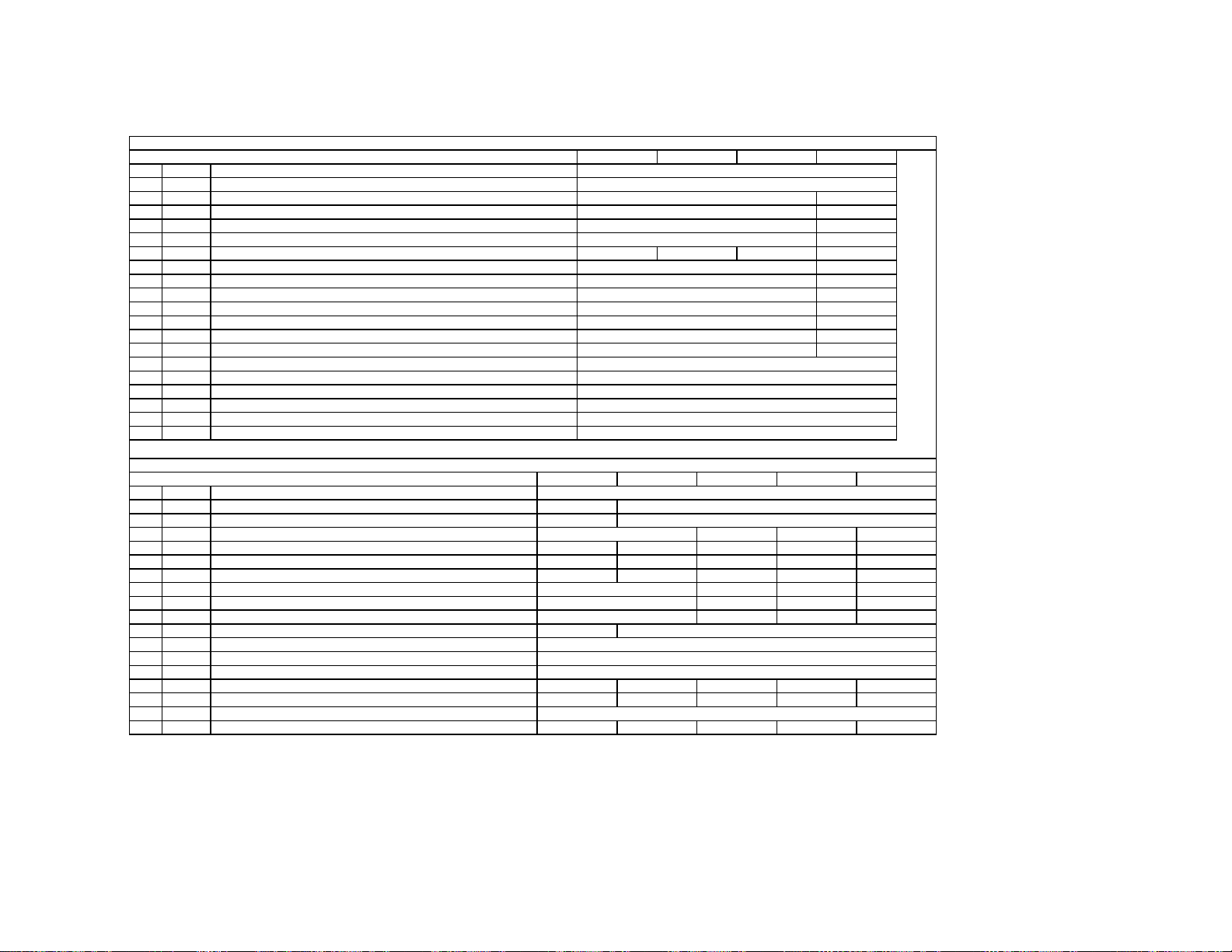
PJ Engine
ITEM ITEM Contents
No. Name
0 FDIS 01
1 COP
2 ALCP 01
3 OSDH 1 255
4 OSD
5 FVSL 015
6 FVSP 0 255
7 V1DL 0 255
8 V1CU 0 4095
9 V1OH 0 255
10 V1OL 0 255
11 OEVP 0 4095
12 COHP 0 4095
13 34CS 031
14 34CW 031
15 FIHP 0 4095
16 TPHP 0 4095
17 TPVP 0 255
18 DFHP 0 4095
19 DFHG -128 127
20 DFVG -128 127
21 DFDC -128 127
22 DFV1 -128 127
23 SDHP 0 4095
24 SDH1 -128 127
25 RVCS 031
26 RVCW 031
27 GVCS 031
28 GVCW 031
29 BVCS 031
30 BVCW 031
31 RHCS 031
32 RHCW 031
Switch of display for fine adjustment data
Service copy adjustmen
Service all copy adjustmen
Osd horizontal position of PJED service menu
Osd vertical position of PJED service menu
Start position of fine adjustmen
Start line of fine adjustmen
Value of V1 dela
Value of V1 count u
Value of V1 offset upper data
Value of V1 offset lower data
Odd/Even select positioin
Horizontal phase for rough adjustmen
Start center clamp positioin of H3 and H4 puls
Width center clamp position of H3 and H4 puls
Horizontal phase for fine adjustmen
Horizontal phase for test pattern
Vertical phase for test pattern
Horizontal phase for dynamic focu
Value of horizontal parabola wave for dynamic focu
Value of vertical parabola wave for dynamic focu
Value of center for dynamic focu
Value of V1 saw wave for dynamic focu
Compensation of horizontal phase for shadin
Value of horizontal saw wave for dynamic focu
Start positioin of Red vertical clam
Width of Red vertical clam
Start position of Green vertical clam
Width of Green vertical clam
Start position of Blue vertical clam
Width of Blue vertical clam
Start position of Red horizontal clam
Width of Red horizontal clam
min max
01
1 255
Zoom
100
0
3
1
454
5
0
55
-70 -70
-65 -65-65
127
-50
127
120
21
139
598
111
127
-50
127
KP-51WS500/57WS500/65WS500
W ZoomNormal HD
-
-
-
22
100
15
25
60
506
5
0
1056
1104
5
0
0
14
0
69
250
127
-50
422
127
0
0
0
0
0
0
0
0
60
014
53
1
387
79
0
1579
-70-70
-65
127
-50
127
— 34 —
SERVICE DATA LISTS
V
V
V
V
V
.
.
.
.
.
e
.
.
.
.
.
.
.
.
.
.
.
.
t
t
C
.
2
2
p
p
p
p
PJ Engine
ITEM ITEM Contents
No. Name
33 GHCS 031
34 GHCW 031
35 BHCS 031
36 BHCW 031
37 BDVU 0 2047
38 BDVL 0 2047
39 BDHL 0 2047
40 BDHR 0 2047
41 HBLD 0 4095
42 HBLW 0 4095
43 PWM2 0 4095
44 COG
45 CORV -128 127
46 COB
47 COGH -128 127
48 CORH -128 127
49 COBH -128 127
50 SOG
51 SOR
52 SOB
53 SOGH -128 127
54 SORH -128 127
55 SOBH -128 127
56 ZOGH -128 127
57 ZORH -128 127
58 ZOBH -128 127
59 LOGH -128 127
60 LORH -128 127
61 LOBH -128 127
62 ERR 063 ADTM 0 127
64 VUP 0 2047
65 VUPM 0 2047
66 VMID 0 2047
Start position of Green horizontal clam
Width of Green horizontal clam
Start position of Blue horizontal clam
Width of Blue horizontal clam
Vertical position for border line 1
Vertical position for border line
Horizontal position for border line 1
Horizontal position for border line
Horizontal phase for output of H.Blank ou
Width for output of H.Blank ou
PWM2 output width setting of Regi I
Green vertical center offset data for Auto Regi
Red vertical center offset data for Auto Regi
Blue vertical center offset data for Auto Regi
Green horizontal center offset data for Auto Regi
Red horizontal center offset data for Auto Regi
Blue horizontal center offset data for Auto Regi
Green vertical skew offset data for Auto Regi
Red vertical skew offset data for Auto Regi
Blue vertical skew offset data for Auto Regi
Green horizontal skew offset data for Auto Regi
Red horizontal skew offset data for Auto Regi
Blue horizontal skew offset data for Auto Regi
Green horizontal size offset data for Auto Regi
Red horizontal size offset data for Auto Regi
Blue horizontal size offset data for Auto Regi
Green horizontal linearity offset data for Auto Regi
Red horizontal linearity offset data for Auto Regi
Blue horizontal linearity offset data for Auto Regi
Auto Regi. Error cod
A/D data input timing of Auto Regi
Auto Regi. Pattern Upper vertical position
Auto Regi. Pattern Upper middle vertical position
Auto Regi. Pattern Middle vertical position
min max
-128 127
-128 127
-128 127
-128 127
-128 127
Normal Zoom W Zoom HD
28
900
21
683
0
0
0
0
148
1262
0
0
730
0
0
0
0
0
0
0
0
0
0
0
0
0
0
0
0
0
0
0
144
50
0
512
12
820
49
1039
KP-51WS500/57WS500/65WS500
— 35 —
SERVICE DATA LISTS
W
W
W
t
t
t
y
t
Y
t
t
y
t
t
t
t
t
y
t
Y
t
t
y
t
t
t
t
t
y
t
Y
t
j
t
y
t
t
t
t
t
y
t
Y
t
t
y
t
t
V
V
V
t
e
e
t
PJ Engine
ITEM ITEM Contents
No. Name
67 VLOM 0 2047
68 VLOW 0 2047
69 HLE 0 4095
70 HLEM 0 4095
71 HMID 0 4095
72 HRIM 0 4095
73 HRIV 0 4095
74 SFTF 01
75 ACTL 076 ACTH 077 SLS
78 VB2S 0 1023
79 VB2
80 VB3S 0 1023
81 VB3
ITEM ITEM Contents
No. Name min max
82 CENT Normal/Full Coarse Center Adjustmen
83 SKEW Normal/Full Coarse Skew Adjustmen
84 SIZE Normal/Full Coarse Size Adjustmen
85 LIN Normal/Full Coarse Linearit
86KE
87 PIN Normal/Full Coarse Pin Adjustmen
88 MLIN Normal/Full Coarse Middle Linearit
89 MSIZ Normal/Full Coarse Middle Size Adjustmen
82 CENT Zoom Coarse Center Adjustmen
83 SKEW Zoom Coarse Skew Adjustmen
84 SIZE Zoom Coarse Size Adjustmen
85 LIN Zoom Coarse Linearit
86KE
87 PIN Zoom Coarse Pin Adjustmen
88 MLIN Zoom Coarse Middle Linearit
89 MSIZ Zoom Coarse Middle Size Adjustmen
82 CENT Wide Zoom Coarse Center Adjustmen
83 SKEW Wide Zoom Coarse Skew Adjustmen
84 SIZE Wide Zoom Coarse Size Adjustmen
85 LIN Wide Zoom Coarse Linearit
86KE
87 PIN Wide Zoom Coarse Pin Ad
88 MLIN Wide Zoom Coarse Middle Linearit
89 MSIZ Wide Zoom Coarse Middle Size Adjustmen
82 CENT HD Coarse Center Adjustmen
83 SKEW HD Coarse Skew Adjustmen
84 SIZE HD Coarse Size Adjustmen
85 LIN HD Coarse Linearit
86KE
87 PIN HD Coarse Pin Adjustmen
88 MLIN HD Coarse Middle Linearit
89 MSIZ HD Coarse Middle Size Adjustmen
Auto Regi. Pattern Lower middle vertical position
Auto Regi. Pattern Lower vertical position
Auto Regi. Pattern left horizontal position
Auto Regi. Pattern left middle horizontal position
Auto Regi. Pattern middle horizontal position
Auto Regi. Pattern right middle horizontal position
Auto Regi. Pattern right horizontal position
Switch of shift fas
Account timer counter lower byt
Account timer counter upper byt
Auto Regi adjustment item selec
Adjustmen
Normal/Full Coarse KeyAdjustmen
Adjustmen
Adjustmen
Zoom Coarse KeyAdjustmen
Adjustmen
Adjustmen
Wide Zoom Coarse KeyAdjustmen
ustmen
Adjustmen
Adjustmen
HD Coarse KeyAdjustmen
Adjustmen
min max
03
0 1023
0 1023
-512 511
-512 511
-512 511
-512 511
-512 511
-512 511
-512 511
-512 511
-512 511
-512 511
-512 511
-512 511
-512 511
-512 511
-512 511
-512 511
-512 511
-512 511
-512 511
-512 511
-512 511
-512 511
-512 511
-512 511
-512 511
-512 511
-512 511
-512 511
-512 511
-512 511
-512 511
-512 511
0
49
42
Green H Green
-
-
-
-
0
106
464
99
KP-51WS500/57WS500/65WS500
16:9
0
975
90
0
655
0
1215
0
0
0
3
0
68
502521
Blue H Blue
-
-
-
-
-
-
-
-
-
-
-
-
16:9
HDW ZoomNormal Zoom
0
9
561
161
Red H Red
-
-
-
-
-
-
-
-
-
-
-
-
-
-
-
-
-
-
-
-
— 36 —
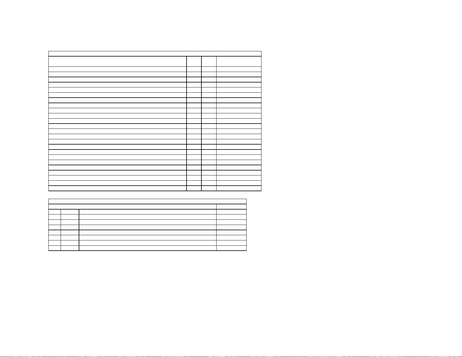
SERVICE DATA LISTS
g
e
s
s
s
s
s
s
s
s
PJ Engine
Contents
Normal/Full Red Horizontal Fine Data
Normal/Full Red Vertical Fine Data
Normal/Full Green Horizontal Fine Data
Normal/Full Green Vertical Fine Data
Normal/Full Blue Horizontal Fine Data
Normal/Full Blue Vertical Fine Data
Normal/Full Zoom Red Horizontal Fine Data
Zoom Red Vertical Fine Data
Zoom Green Horizontal Fine Data
Zoom Green Vertical Fine Data
Zoom Blue Horizontal Fine Data
Zoom Blue Vertical Fine Data
Wide Zoom Red Horizontal Fine Data
Wide Zoom Red Vertical Fine Data
Wide Zoom Green Horizontal Fine Data
Wide Zoom Green Vertical Fine Data
Wide Zoom Blue Horizontal Fine Data
Wide Zoom Blue Vertical Fine Data
HD Red Horizontal Fine Data
HD Red Vertical Fine Data
HD Green Horizontal Fine Data
HD Green Vertical Fine Data
HD Blue Horizontal Fine Data
HD Blue Vertical Fine Data
min max
-128 127
-128 127
-128 127
-128 127
-128 127
-128 127
-128 127
-128 127
-128 127
-128 127
-128 127
-128 127
-128 127
-128 127
-128 127
-128 127
-128 127
-128 127
-128 127
-128 127
-128 127
-128 127
-128 127
-128 127
KP-51WS500/57WS500/65WS500
data
0
0
0
0
0
0
0
0
0
0
0
0
0
0
0
0
0
0
0
0
0
0
0
0
ID
Re
0 ID0
1 ID1
2 ID2
3 ID3
4 ID4
5 ID5
6 ID6
7 ID7
.No &Nam
Selection of OSD languages & color system
Selection of composite & s-video input
Selection of audio-related control
Selection of basic system setting
Selection of basic system setting
Selection of advanced system setting
Selection of sub picture related setting
Selection of some reserved setting
FUNCTION
89
127
239
98
203
177
54
24
— 37 —
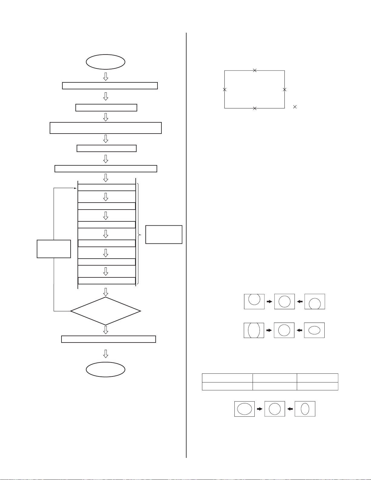
KP-51WS500/57WS500/65WS500
2-12. REGISTRATION ADJUSTMENT
*ADJUSTING FLOW
START
Turn on the power and wait for 10 minutes.
Set to the NTSC Full mode
Check the deflection yokes, the centering magnets,
2-pole/4-pole magnets
Set to the service mode.
MAIN DEFLECTION ADJUSTMENT (Green)
Green coarse adjustment
Green fine adjustment
2-12-1.SETUP FOR ADJUSTMENT
MARKING
• At the 4 sides of the screen, use a tape measure to locate the middle.
: middle
DATA SETTING
1. Set NTSC Full mode.
2. Enter the service mode, and select “PJE”.
NOTE: When you replace printed circuit boards, devices, or CRTs, and
when correction is drastically necessary, press the “7” + ENTER on the
remote commander to initialize the data in the Projector Engine mode.
Press MUTING + ENTER on the remote commander to write the data.
2-12-2.MAIN DEFLECTION ADJUSTMENT
NOTE: Before this adjustment, refer to section 2-11 for PJE input data
items #78-85.
Change the
display mode
ALLCOPY*
When the
*
NTSC Full mode
adjustment has finished,
copy its data to
the next
display mode the
first time only
and be sure to
adjust in the order given.
Yes
Memorize the FLASH FOCUS offset data
Red coarse adjustment
Red fine adjustment
Blue coarse adjustment
Blue fine adjustment
Another display mode?
No
End
SUB
DEFLECTION
ADJUSTMENT
1. Cover the red and blue CRT lenses with lens caps to allow only green
to show (or use the method shown in the note below for turning off the
CRTs individually without using lens caps).
2. Enter the monoscope signal and set to NTSC Full mode.
3. Enter the service mode, and select “2150D-1”.
4. Adjust “0 VPOS” and “1 VSIZ” so that the picture is displayed in the
center of the screen.
5. Adjust “2VSZ0” for 1080i vertical size adjustment.
0 VPOS
1 V-Size
6. Select “2150D-2” and adjust “2 H-Size” so that the picture size is
within the specifi cation.
SPEC Overscan Spec. = 9%
Input Signal H SIZE V SIZE
Monoscope 15.6 ± 0.2 sq. 11.5 ± 0.2 sq.
2 H-Size
7. Copy the data of the NTSC Full mode to the other display mode and,
if necessary, adjust in the other mode.
— 38 —
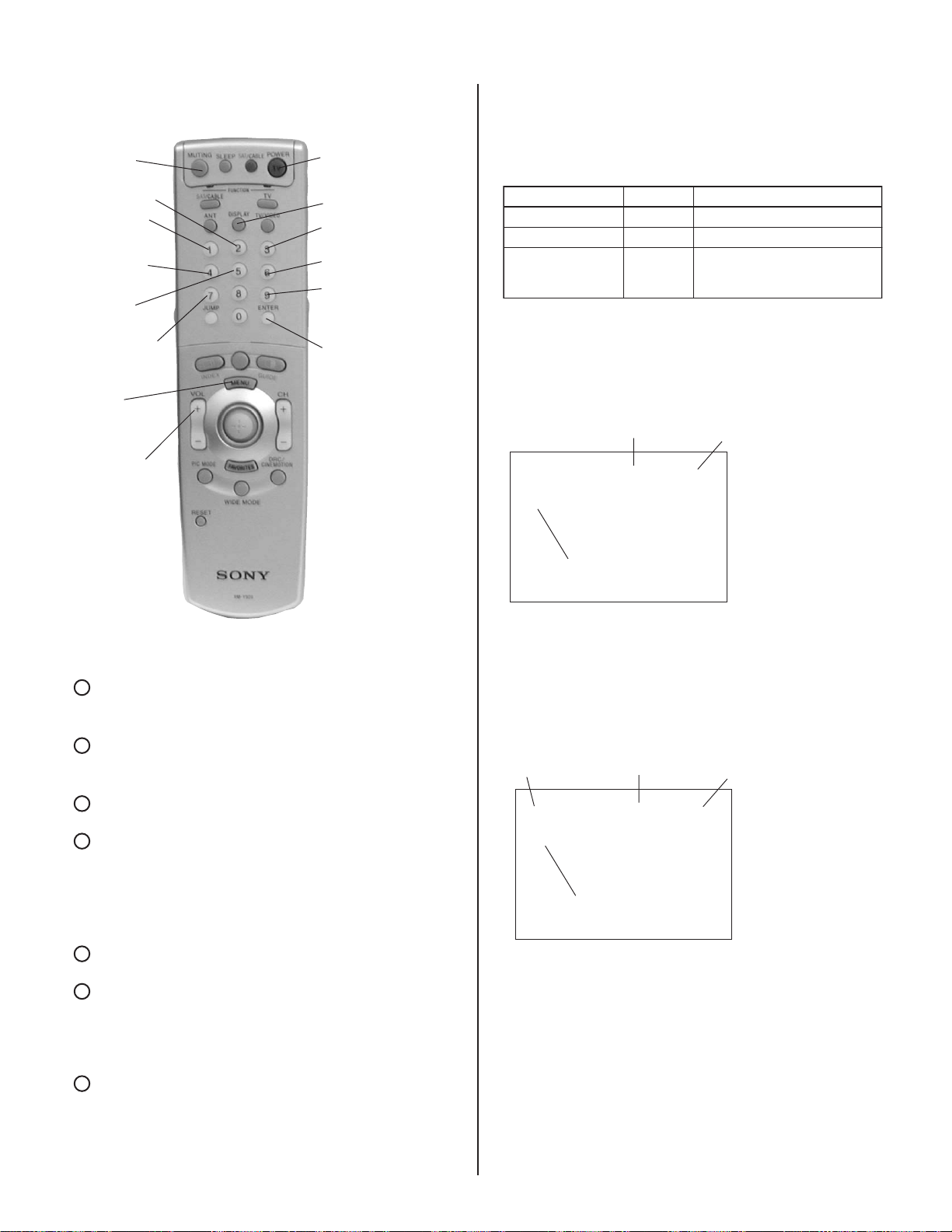
KP-51WS500/57WS500/65WS500
2-12-3.OPERATION METHOD FOR
PROJECTOR ENGINE MODE
MUTING
Category up
Adjustment
item up
Adjustment
item down
Category
down
Initialize data
(Not stored)
MENU
Data Up/
Down
VOLUME +
POWER
DISPLAY
Color Select GRN
to BLU to RED
Internal Test signal
Mode Select
(Course Adjustment
Fine Adjustment)
ENTER
Press Switches marker moving method.
Joystick (In Fine Adjustment mode)
Joystick
Commander Function
Buttons Mode Description
MUTING+ENTER WRITE Writes data from NVM.
2. OPERATION METHOD FOR COARSE ADJUSTMENT
1. Enter the service mode and select “PJE”.
2. Press the “1” or “4” button on the remote commander to select the
5 6 3 4
0 + ENTER READ Reads data to NVM.
7 + ENTER PJE Service data initialization.
item, and then use the joystick to change the data.
PJE 00 00
FDIS
keys Æ 1 and 4 buttons
INITIAL
Item No.
Not stored.
(Be sure not to use usually)
Data
RM-Y909
1. FUNCTION OF KEYS ON COMMANDER
1 Changes adjustment item. (Item # moves up)
Marker moves clockwise from center to outside.
(In Fine Adjustment mode)
4
Changes adjustment item. (Item # moves down)
Marker moves counter clockwise from outside to center.
(In Fine Adjustment mode)
2
Changes adjustment category.
(Category # moves up)
5
Changes adjustment category.
(Category # moves down)
Joystick Changes data value. (Up or down)
Marker moves clockwise from center
(up, down, right, and then left) to outside.
(In Fine Adjustment mode)
3
Changes adjustment color.
GRN ÆBLU ÆRED
6
Displays or changes internal test signals.
crosshatch + external signal Æ
crosshatch + borderline Æ
crosshatch only Æ
dot only Æ off
9
Switches adjustment mode.
Coarse adjustment model Æ
Fine adjustment mode
Joystick
Adjustment Item
3. Select “GRN CENT”. When BLU or RED is displayed, press the “3”
button on the remote commander to change the adjustment color
in the order of GRN ÆBLU ÆRED.
4. In GRN, BLU, or RED mode, move the joystick 5 or 6to change
the data in vertical direction, or 3 or 4 to change the data in a
horizontal direction.
Color
GRN 000 000
CENT
Adjustment Item
5. Before returning to the service mode, press the “MUTING” +
“ENTER” buttons on the remote commander to write the data.
(You must complete step 5 to write the data. If you omit step 5 the
set data is returned to the data prior to the adjustment.)
3. OPERATION METHOD FOR FINE ADJUSTMENT
1. Enter the service mode and select “PJE”.
2. Select FDIS and set the data to “01” so that the data at each
position can be displayed in fi ne adjustment mode.
Data (H)
Data (V)
direction:Data up
54
direction:Data down
63
: Data (H) up
3
: Data (H) down
4
: Data (V) up
5
: Data (V) down
6
— 39 —

KP-51WS500/57WS500/65WS500
3. Press the “9” button on the remote commander and fi ne
adjustment mode will be active where a green marker appears in
the center of the screen. (In the case of GRN mode)
4. Press down on the joystick, and the marker color will be alternately
switched between green (GRN mode) and white.
5. Press the “1” or “4” button on the remote commander, or use the
joystick to move the marker to the position to be adjusted, where
fi ne adjustment can be made.
* When the marker color is white:
(in this case, fi ne adjustment is disabled)
Use the joystick to move the marker up, down, left, or right.
* When the marker color is green:
(GRN mode)
2-13. PJE ADJUSTMENT (SUB DEFLECTION ADJUSTMENT)
Note: If the value is over the limit value, adjust these in the fi ne
adjustment mode.
Coarse Data Limit Value:
Adjustment type
Adjustment item G R B
H/V* H/V* H/V*
CENT O/O O/O O/O
SKEW O/O O/O O/O
SIZE O/O O/O O/O
LIN O/O O/O O/O
KEY -/O -/O -/O
PIN O/O O/O O/O
MLIN O/- O/- O/MSIZ O/- O/- O/
* H = Horizontal V = Vertical O = Yes = No
CENT H 35 ± 170V
CENT V 20 ± 170V
SIZE H -75 MAX
BLUE H LIN -425 MIN
RED H LIN 425 MAX
1
: Moves the marker clockwise from the center to the outside.
4
: Moves the marker counter clockwise from the outside
to the center.
* Fine adjustment can be made on the basis of a marker position
using the joystick to move
Move joystick 5 direction
CROSSHATCH
6. Press the “9” button on the remote commander to return to coarse
adjustment mode.
5 6 3 or4.
Move joystick
4
direction
CROSSHATCH
2-13-1.ADJUSTMENT FOR NTSC FULL MODE
• The adjustment should be done in the numerical order given.
1) GREEN ADJUSTMENT
1. Cover the red and blue CRT lenses with lens caps to allow only green
to show (or use the method shown in the note below for turning off the
CRTs individually without using lens caps).
Note: If lens caps are unavailable, you can cut off the unnecessary color
beams by controlling the service mode 2150P-2 1 RGBS.
2. Enter the monoscope signal to set.
3. Select the PJE mode.
4. Press the “6” button on the remote commander to display the internal
test signal (crosshatch).
5. Select “GRN CENT”, and adjust so that the pictures coincide in the
center of screen.
GRN CENT (Horizontally/Vertically)
Push the joystick
to
Push the joystick
to
— 40 —
Push the joystick
Push the joystick
 Loading...