

Page 1

Instruction Manual
Video Camera Housing for
SONY
Before operating the unit, please read this manual carefully. Keep it for
future reference.
® HDR-FX1 & HVR-Z1
Page 2

INTRODUCTION & FEATURES
PHENOM FXZ1
Marine housing for the Sony HDR-FX1 & HVR-Z1
Amphibico launches its all new, full-featured PHENOM FXZ1 HDV marine housing. Following in the same highly
innovative footsteps as the Amphibico VH1000 and subsequent world-renowned underwater video housings, the new
PHENOM FXZ1 will be just that.......PHENOMENAL!!
This full featured housing will provide access to all key camcorder functions to depths of 330 feet (100 meters).
Amphibico's high quality full zoom-through 94° optics will complement the package.
FEATURES
o 14 Electronic push button controls
o 6 Mechanical controls
o Power On/Off
o Record/Standby
o Variable speed ZOOM T/W
o True manual focus (Electronic gear driven)
o "One Push" manual white balance
o Shutter speed adjustment
o Iris (Auto / Manual), full control
o Gain adjustment
o Access to the camcorder ND filters
oEffects
o Screen Display
o Dual Video Signals
o Switch able audio Channels
o Access to the camcorder's menu
o Toggle between Manual and Auto Focus
o VCR functions: Play, Stop, Rewind, Fast Forward, Pause
o Index marker with index search functions
o Flashing Green Tally Light when Recording
o Infrared interface for accessory remote carry handle
o Fire Wire capability for direct download
o Electronic Moisture Sensor Alarm
o Remote On/Off light switches
1
Page 3

TABLE OF CONTENTS
Unpacking Your Housing....................................................................................3
Housing Features and Controls......................................................................4-5
Preparing the Camera & Housing.................................................................6-10
Opening the housing..............................................................................6
Removing the saddle.............................................................................6
Setting the camcorder............................................................................6
Setting the saddle..................................................................................7
Installing the saddle...............................................................................7
Connecting the saddle...........................................................................7
Placing the camcorder...........................................................................8
Closing the housing...............................................................................8
Adjusting the IRIS and MENU knobs.....................................................9
Viewfinder eyepiece adjustment............................................................9
Replacing the bayonet lens....................................................................9
Installing accessories...........................................................................10
Water Entry...........................................................................................10
Housing Camera & Operations...................................................................11-15
Power ON/OFF.....................................................................................11
Power save..........................................................................................11
Mode settings.......................................................................................11
Zooming...............................................................................................12
Focusing...............................................................................................12
White balance......................................................................................13
Light buttons.........................................................................................13
Effects...................................................................................................14
Review..................................................................................................14
Index marker.........................................................................................14
Back light..............................................................................................14
Display..................................................................................................14
Menu....................................................................................................15
Iris adjustment knob.............................................................................15
ND filter knob........................................................................................15
Gain......................................................................................................15
Shutter..................................................................................................15
Maintenance.......................................................................................................16
Servicing O-rings..................................................................................16
Specifications....................................................................................................17
Optional Accessories........................................................................................18
General Shooting Tips......................................................................................19
Warranty.............................................................................................................20
2
Page 4
UNPACKING YOUR HOUSING
Before unpacking your housing kit, inspect the shipping box as well as all contents for damage during shipping.
If damage has occurred, please contact the shipping company immediately.
Every Amphibico Housing is pressure tested prior to shipping. However, damage may have occurred during shipping.
It is strongly recommended to test dive the housing once without camcorder installed to insure the housing is water tight.
This instruction manual assumes that the user is already familiar with the SONY® HDR-FX1 and HVR-Z1 camcorders.
If not, please read instruction manuals thoroughly before beginning to use the housing.
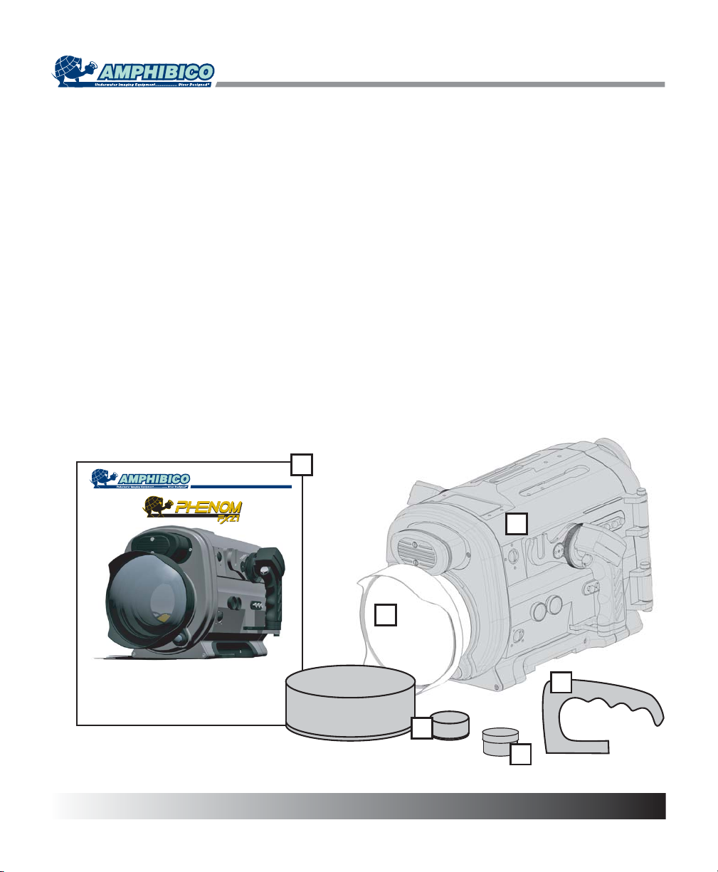
Your PHENOM FXZ1 camcorder housing comes to you as follows:
A) Marine Housing G) Carry Handle
B) 94° wide Angle bayonet mounted lens H) Allen Key 5/32" (for carry handle)
C) Removable / lockable camcorder saddle I) Allen Key 1/16" (for lead ballasts)
(shipped in its position inside the housing)
D) Front & rear neoprene covers for the lens and viewfinder J) Allen Key 5/64" (for menu navigation & Iris wheel)
E) O-ring kit with container of silicone grease
F) Instruction manual and warranty card
F
Instruction Manual
Video Camera Housing for
® HDR-FX1 & HVR-Z1
SONY
Before operating the unit, please read this manual carefully. Keep it for
future reference.
A
B
G
D
E
3
Page 5
HOUSING FEATURES &CONTROLS
8
1
2
3
4
5
4
6
7
9
10
11
12
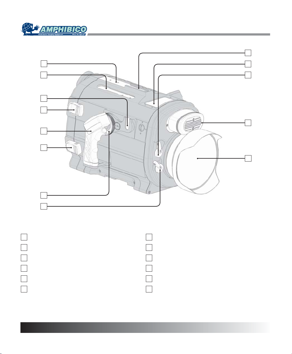
1
Accessory Mounting Holes
2
Accessory Mounting Top Rail
3
Accessory Mounting Side Rail
4
Safety Latch
5
Right Electronic Grip
6
Zoom Wheel
4
7
Color Correction Flip Filter Lever
8
Carry Handle Mounting Rail
9
LCD Display Window
10
Spare Flip Filter Lever
11
Dual Hydrophone
12
Bayonet Mount Wide Angle Lens Port
Page 6
HOUSING FEATURES &CONTROLS
17
13
14
15
16
Iris
Gain
18
19
20
21
Shutter
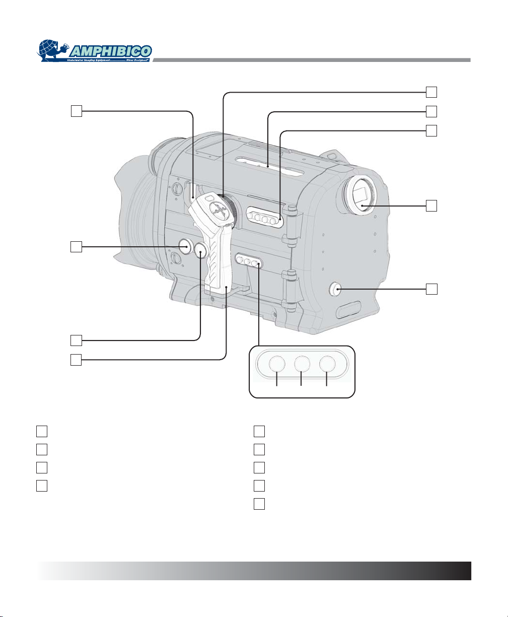
13
Accessory Mounting Side Rail
14
Iris Adjustment Knob
15
Camcorder ND Filter Knob
16
Left Electronic Grip
17
Focus Wheel
18
Accessory Mounting Top Rail
19
Control Panel
20
Viewfinder
21
Menu Navigation Wheel
5
Page 7
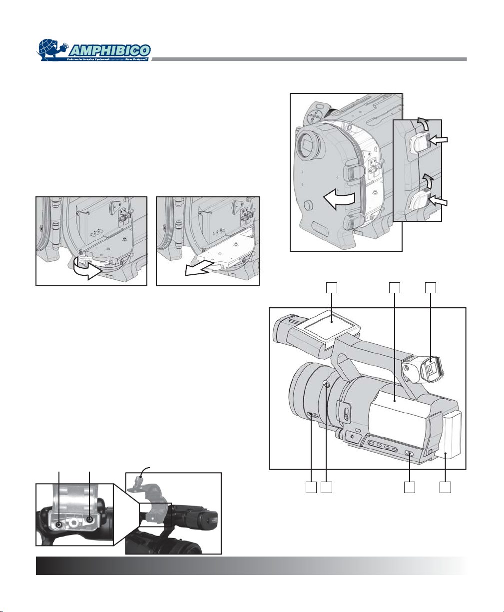
OPENING THE HOUSING
Sit the housing on a flat surface. Press and rotate both safety
latches counterclockwise simultaneously until the rear door
opens.
REMOVING THE SADDLE
1. Rotate the saddle locking handle towards the right until it
reaches the end. This will disengage the saddle connector.
2. Use the handle to pull the saddle completely out of the
housing.
PREPARING CAMCORDER & HOUSING
1
SETTING THE CAMCORDER
1. Remove the eyecup and magnifier element. Rotate the
viewfinder for it to line up with the housing's own magnifier
element.
2. Rotate and flip the LCD panel to restore it back to the
original position with the LCD screen facing out.
3. Put a fully charged battery in the camcorder.
4. Place a recordable tape into the camcorder.
5. Set the AUTO LOCK switch to the center position.
6. Set the ZOOM switch to LEVER/REMOTE position.
7. Rotate the zoom ring so its knob is pointing upwards.
NOTE: You will have to remove the external MIC support
holder in order to fit the HVR-Z1 camcorder into the housing.
1. Open support holder to expose the mounting screws.
2. Unscrew both screws and remove support holder.
3. Replace screws into there mounting holes for safe keeping.
Mounting Screws
2
MIC Support Holder
6
142
7
356
Page 8

PREPARING CAMCORDER & HOUSING
SETTING THE SADDLE
AUDIO
Factory settings for the audio on the PHENOM have both
channels set to HYD (Hydrophone). Switching audio settings
to EXT permits you to use external audio equipment when
connected to the PHENOM bulkhead connectors (optional).
ZOOM
The range on the zoom wheel (p.12) can be adjusted on the
saddle. Set the ZOOM to FULL if you want to zoom through
the entire camcorder's range (wide to telephoto). MED only
allows you to zoom from wide to mid-telephoto.
INSTALLING THE SADDLE
Place the saddle under camcorder with its handle pointing
the back of the camcorder. Align the thumb screw's saddle
and guide pin with the camcorder's tripod mounting holes.
Hand tighten the thumb screw to secure the saddle to the
camcorder.
CONNECTING THE SADDLE
LANC: Connect the cable from the rear of the saddle to the
camcorders LANC jack.
VIDEO: Connect the video cable (yellow band) terminated
with a 3.5mm plug to the camcorder's A/V jack. The other
video cable is connected to the S VIDEO connector.
AUDIO (HDR-FX1): Connect the audio cable from the front
of the saddle to the camcorder's MIC jack.
AUDIO (HVR-Z1): Connect the adapter plug (supplied) to
the camcorder's INPUT 1 MIC jack. Connect the audio cable
from the front of the saddle to adapter plug.
NOTE: It is important to route all cables as shown in the
diagram. This will prevent any damages to the cables when
inserting the saddle into the housing.
Settings
Installing
Thumbscrew
Connecting the HDR-FX1
LANC
MIC (INPUT 1)
Connecting the HVR-Z1
A/V
S VIDEO
LANC
S VIDEO
A/V
MIC
7
Page 9

PLACING THE CAMCORDER INTO THE HOUSING
By now the camcorder is set, installed to the saddle and
ready to be placed inside the housing.
1. Line up the camcorder and saddle with the docking tray
found inside the housing.
2. Begin to insert the camcorder by placing the front of the
saddle over the docking tray. This will allow you to better
locate the rails on the docking tray.
3. Slide the camcorder all the way until the saddle connector
makes contact with the docking tray connector.
4. Rotate the handle on the saddle to secure the camcorder
into the housing. This will also guaranty a perfect connection
for the saddle connector.
5. Set the power switch on the camcorder to CAMERA.
NOTE: It is essential for the camcorder to be turned ON in
order for the housing electronic features to work properly.
PREPARING CAMCORDER & HOUSING
CLOSING THE HOUSING
1. While the housing is open, inspect the two o-rings and
the sealing surface for dirt and debris. If necessary, clean
them with a lint free tissue. Make sure that the two o-rings
and the sealing surface are clean. Then apply a small
amount of lubricant (supplied) to the o-rings.
NOTE: If you have to change your o-rings, make sure you
are using the o-rings provided with the package. Using
different o-rings than those in the o-ring kit may cause the
housing to leak and result in damage.
2. Make sure that the LANC cable doesn't block the sealing
surface. If that cable gets pinched, the system might be
intermittent or not functioning at all. Close the rear door until
the latches begin to engage.
3. Make sure the o-rings are well placed before locking the
latch. Turn the latch clockwise until a positive click is felt.
8
Page 10

PREPARING CAMCORDER & HOUSING
ADJUSTING THE IRIS AND MENU KNOBS
Both the IRIS and MENU knobs are factory adjusted.
However these knobs may need to be adjusted because
camcorders do tend to vary in size, Therefore, it is
recommended to try out these two knobs after the initial
camcorder insertion (p.8). Difficulty in operating either the
IRIS or the MENU knob could indicate that adjustments are
required on the knobs.
To make the adjustments
1. Remove the camcorder from the housing.
2. Using the supplied allen key, loosen the set screw of
either the IRIS or MENU knob mechanism as illustrated. This
will release the o-ring friction plate and allow you to adjust it
by turning it CW or CCW for more or less friction on the
camcorder. Once the adjustment is made, re-tighten the set
screw.
3. Replace the camcorder into the housing and try the knobs
once again for proper operation. Repeat procedure if
necessary.
VIEWFINDER EYEPIECE
The viewfinder eyepiece located on the
rear of the housing may also need
adjustment. To adjust, simply turn the
inside ring on the viewfinder CW or
CCW to achieve perfect focus with the
camcorder viewfinder. Tighten the
locking ring up against the viewfinder
body to lock the eyepiece in place once
adjusted.
Locking Ring
Adjustment
Ring
IRIS knob mechanism
Allen Key (supplied)
MENU knob mechanism
REPLACING THE BAYONET LENS
The PHENOM is provided with a wide angle bayonet
mounted lens. In order to protect the optics, covers are
provided with the lens.
1. To remove the lens, push and hold the button on the lower
right of the front bulkhead and then turn counter clockwise
until the lugs are free from the bayonet ring. Pull gently on
the lens to release it.
2. Remove the covers from the replacement lens. Place
them in a clean and dry environment to avoid any damage.
Make sure the seals on the bottom part of the lens are clean
and free from dust and debris.
3. Put a small amount of lubricant on the o-ring seals and
the sealing surface of the housing.
4. Line up the bayonet lug marked by a hole with the printed
dot on the front bulkhead of the housing. Push the lens all
the way until it sits on the bayonet ring and turn clockwise.
You will hear a positive click and the lens will lock into place.
release button
Lens
9
Page 11

INSTALLING ACCESSORIES
The PHENOM as been equipped with mounting holes and
railing systems to accommodate for a variety of accessories.
Locations for a few of these accessories have been
designated for your convenience. However, these locations
can be used for other accessories. Some accessories like
the monitor or video lights require to be connected to the
housing. Accessory connector ports (one on the right side
and two on the left side) are available for this purpose.
Achieving neutral buoyancy and balance
Adding accessories to the housing may make it heavier or off
balance in the water. Removable ballasts have been added
to the bottom of the housing for this purpose.
To make the necessary weight adjustments.
1. Submerge the housing with the added accessories
into the water so you get an idea of what and where to
remove weight.
2. Using the allen key supplied, start removing or
relocating the ballasts from the right or the left channels
as illustrated.
WATER ENTRY
1. Always turn housing to its ON position before entering
water. To turn it ON, use the right grip trigger button. This is
confirmed by the CAM. indicator light turning on steady
green. The camcorder viewfinder will also turn ON.
Doing step 1 will activate the built-in moisture alarm sensor
located in the bottom of the housing.
IMPORTANT
All indicator lights will start flashing RED if water
leakage occurs inside the housing. Remove from water
as soon as possible, take the camcorder out of the
housing and inspect all seals and the inside of the
housing. ALWAYS REMEMBER DIVER SAFETY FIRST.
2. Lower the housing just below the water surface in level
position and hold for one minute to confirm there is no
leakage in the housing.
Never leap into the water while holding the housing. Always
have the housing handed to you or lowered down once you
are in the water.
3. Point the lens of the housing upwards and shake off any
air bubbles. It may also be necessary to gently wipe the lens
with your finger to remove bubbles.
PREPARING CAMCORDER & HOUSING
"T" bracket
CAM
Monitor bracket
Carry handle
Right Grip
PWR SAVE
VCR
Z
W
-
M
O
O
Z
W
B
O
O
M
-
T
S
U
C
O
F
Trigger Button
Video lights
Video lights
Accessory
connector port
Allen key (supplied)
Ballast
10
Page 12

HOUSING & CAMCORDER OPERATION
The PHENOM offers a large range of functions both
electronic and mechanical. This chapter will explain to
you in detail all of these functions.
POWER ON
The camcorder should be powered ON by default after
inserting it into the housing. In the event that it's not, the
trigger button on the right grip will activate the camcorder.
Simply press on it once and the CAM indicator light will turn
on steady green and the rear viewfinder will also be turned
on to confirm the power ON of the camcorder.
POWER OFF
To power off the camcorder during a dive will allow you to
save on battery energy. To do so, find the power OFF switch
on the menu panel and hold it for at least 2 seconds.
POWER SAVE
(All LED indicators are on steady green)
When the camcorder is left in Record/Standby for more than
5 minutes, it will exit this mode to prevent tape wear and
battery loss. In Power Save mode, you have two choices:
1. To set it back to Record/Standby mode: Press on the left
grip trigger button (shift key) together with the right grip
trigger button.
2. To start recording immediately: Simply press on the right
trigger button. Note that it will take longer to start recording.
MODE SETTINGS
There are two mode settings on the housing. One mode
setting is for the CAMERA operation (CAM MODE) and the
other is the VCR operation (VCR MODE) of the camcorder.
You can change mode settings, once the housing is
activated, by pressing on the MODE switch located on the
control panel.
CAM MODE
The housing will set itself to record/standby mode (CAM
indicator LED is steady green) when initially turned ON. To
record a scene, simply press on the right grip trigger button.
The CAM indicator LED will flash green when recording.
Pressing it again will bring it back to record/standby mode.
VCR MODE
In VCR mode, all playback functions on both grips become
available. The CAM indicator LED turns off and the VCR
indicator LED turns on steady green in this mode.
Left Grip Right Grip
: Index-Rewind : Rewind
: Index-Forward : Fast-Forward
: Search Mode : Stop
SM
: End Search : Play
ES
Trigger B.: Pause
Trigger button (shift key)
Power ON
Right grip trigger button
MODE
Control panel switch
Left Grip
PWR SAVE
CAM
T
H
G
I
L
T
F
E
L
E
F
F
E
C
T
S
SM
VCR
R
I
G
H
T
L
I
G
H
T
W
E
I
V
E
R
ES
Left Grip
Power OFF
Control panel switch
Right Grip
PWR SAVE
CAM
W
-
M
O
O
Z
W
B
VCR
Z
O
O
C
O
F
M
-
T
S
U
11
Page 13

HOUSING & CAMCORDER OPERATION
ZOOMING
On the PHENOM, zooming is achieved either with the zoom
wheel or the right grip's ZOOM-W and ZOOM-T buttons.
Zoom Wheel
The zoom wheel enables you to vary the zoom speed.
ZOOM-W and ZOOM-T
Located on the right grip, the ZOOM-W and ZOOM-T
buttons enables you to zoom through with a constant speed.
Pressing on ZOOM-W will widen the zoom while pressing on
ZOOM-T will result in the opposite being telephoto.
Slower Zoom Speed: If so desired, the zoom speed may be
reduced. Simply hold down the left grip trigger button (shift
key) while pressing on the ZOOM-W or ZOOM-T buttons.
FOCUSING
The camcorder focus on the PHENOM can be set to either
auto or manual focus. To toggle from auto to manual focus,
hold down the left grip trigger button (shift key) while
pressing on the right grip FOCUS button.
Manual Focus
In manual focus, you can:
1. Use the focus wheel to fine adjust the focus.
2. Use the right grip FOCUS button (by holding it down) to
temporally auto focus. Letting go will return to manual focus.
PWR SAVE
CAM
W
-
M
O
O
Z
W
B
Focus Wheel
Right Grip
PWR SAVE
CAM
W
-
M
O
O
Z
Right Grip
VCR
Z
O
O
M
-
T
S
U
C
O
F
VCR
Z
O
O
M
-
T
Zoom Wheel
Left Grip
Trigger Button
(shift key)
Zoom and Focus Wheel functionality
Both the zoom and focus wheel operate in the same fashion.
The wheels are spring loaded and maintain a zero (non
active) position when not in use. Applying a little movement
on the wheel in either directions will result in a slow speed.
Increasing the movement on the wheel will accelerate the
speed.
12
W
B
S
U
C
O
F
Page 14

Page 15

HOUSING & CAMCORDER OPERATION
EFFECTS
The HDR-FX1 & HVR-Z1 camcorders do not support this
feature at the present moment.
REVIEW
The REVIEW button located on the left grip allows you to
review the last few seconds of the most recently recorded
scene while in record/standby mode.
INDEX MARKER
The index marker function included in the Phenom allows
you to make an index for a scene. Pressing on the left grip
trigger button (shift key) together with the REVIEW button
will record an index signal.
BACKLIT
Control panel switch
Left Grip
PWR SAVE
CAM
T
H
G
I
L
T
F
E
L
E
F
F
E
C
T
S
SM
VCR
R
I
G
H
T
L
I
G
H
T
W
E
I
V
E
R
ES
Trigger button (shift key)
CAM
H
G
I
L
T
F
E
L
E
F
F
E
C
T
S
SM
Left Grip
PWR SAVE
T
Left Grip
VCR
R
I
G
H
T
L
I
G
H
T
W
E
I
V
E
R
ES
BACK LIGHT
The BACKLIT button located on the control panel lets you
turn ON or OFF the camcorder's back light function.
DISPLAY Toggle
This function allows you to display ON or OFF the
camcorder's information in the viewfinder while recording or
in playback mode. To access this function, simply press on
the left grip trigger button (shift key) together with the MODE
button on the control panel.
DISPLAY Mode
In playback mode (VCR), you can either have the date/time
displayed or the camera settings displayed in the viewfinder.
Press on the left grip trigger button (shift key) together with
the MENU button on the control panel to switch back & forth.
14
MENU (Display Toggle)
Control panel switch
MODE (Display Mode)
Control panel switch
Page 16

HOUSING & CAMCORDER OPERATION
MENU
Press on the MENU button located on the control panel to
access the camcorder's menu. Once activated, you can
navigate through the menu by rotating the menu navigation
wheel located at the rear of the housing. Depressing this
wheel will allow you to enter sub menus and make menu
changes. Press on the MENU button once again to exit.
IRIS ADJUSTMENT KNOB
You must first make sure that the iris is set to manual. The
current aperture value (f) will be displayed in the viewfinder if
the iris is set to manual. If not, press on the Iris button
located on the panel behind the left grip. This will set the iris
to manual, rotating the Iris knob CW or CCW will make the
aperture value of the camcorder change.
ND FILTER KNOB
Use the ND filter knob to change from no ND filter to ND filter
1 or ND filter 2. The following procedure describes how to
use this feature.
To increase the filter number:
Rotate the knob all the way CW without
depressing it. Depress the knob and
rotate CCW while looking through the
viewfinder. Stop and let go of the knob
when you have reached the desired
setting.
To decrease the filter number:
Rotate the knob all the way CCW without
depressing it. Depress the knob and
rotate CW while looking through the
viewfinder. Stop and let go of the knob
when you have reached the desired
setting.
GAIN
You can set the camcorder to one of its preset gain levels
(H,M,L) by simply pressing on the Gain button located on the
panel behind the left grip. Once activated, you can change
its value in the gain setup sub menu via the menu button
and menu navigation wheel.
Control panel switch
MENU
Iris adjustment knob
ND filter knob
Menu navigation wheel
Gain
Iris
Shutter
SHUTTER
Pressing on the Shutter button located on the panel behind
the left grip allows you to manually adjust and fix the shutter
speed. Once depressed, use the menu navigation wheel to
adjust and fix the shutter speed. Pressing on the Shutter
button once again will return it to automatic adjustment.
15
Page 17

MAINTENANCE
WARNING: DO NOT leave the housing exposed to direct sunshine, as extreme heat condition can be detrimental
to certain of its components.
1. Keep housing and o-rings away from direct sunlight. Always store unit when possible away from direct sunlight as this
can dry out and crack o-rings in the housing. Ultraviolet rays can damage plastics, paint and o-rings.
2. Always rinse or soak closed housing in fresh water for 10 to 15 minutes after every use. Reach into freshwater and
operate all controls to clear salt water. Do not use solvents to clean unit. If preferred, use mild detergent and clean fresh
water.
3. Fasteners that are removable should occasionally have the threads lubricated with silicon grease.
4. Rinse clean and remove water spots from external filters and lens surface after every dive or water spots may build up
and become impossible to remove. Dry gently with a soft, lint-free cloth.
5. Inspect housing's rear door main o-ring seals (double seals) before every dive. Make sure that there are no cracks or
misalignment in the o-ring channel and that no debris is caught on the o-rings.
SERVICING O-RINGS
1. O-rings and sealing surface should be lightly lubricated with silicon lubricant on a regular basis. This is not necessary
after every dive; every tenth dive during regular heavy use is sufficient. This should always be done before storing the
housing and before a first dive after taking the housing out of storage.
2. It is important never to use a sharp instrument when removing an o-ring as this may cause damage to the o-ring or the
o-ring groove. A hairpin or a credit card works well.
3. The removed o-ring should be examined for damage. Check to make sure that the o-ring is free from nicks and cuts
and that it retains its original round profile. O-rings that appear to be damaged should be discarded immediately and
replaced with new o-rings.
4. Rinse the o-ring with freshwater and dry it with a clean lint free cloth.
5. Clean the o-ring grooves (where the o-rings sit) with a Q-tip. Be sure to remove any lint the Q-tip may leave behind.
Inspect the groove for damage.
6. Wipe the part of the housing that the o-ring seals against with a clean lint free cloth.
7. Re-grease the o-rings with a thin layer of silicon grease until it appears to be smooth and shiny. Do not over grease it -
use just enough grease so that the o-ring will pull smoothly through your fingers. Excessive amounts will only attract dirt to
the o-ring.
8. Replace o-rings in their proper position on the lens assembly and on the main door seal.
16
Page 18

SPECIFICATIONS
PHENOM
Marine housing for the Sony HDR-FX1 & HVR-Z1
- Marine grade aluminum Construction
- Fully anodized with a hard coat of polyurethane paint and a clear coat
- All hardware is marine grade brass and stainless steel
- Optics: Marine bayonet mounted lens system, 0.68X rectilinear fully coated amphibious conversion lens.
Full zoom-through capability, 94° field of view underwater and vacuum-sealed for maximum anti-fog protection
- Dual Internal Flip filters with a Blue Water and Neutral Density filters installed
- Sensitive Dual Hydrophones to pick up high frequency sounds, such as whales and dolphins
- 2.5 x Magnified viewfinder with adjustable diopter control
- 3 Auxiliary ports
Weight of unit :
- On land 36 lbs. (16.3kg) fully loaded w/camera NP970 battery, lens and lead ballasts.
- In seawater the Phenom is perfectly balanced and neutral buoyancy
Dimensions :
- Length 18.3" (465mm)
- Width 13.6" (345mm)
- Height 10.1" (257mm)
- Measurements includes lens and grips
Operating depth :
- Each unit is pressure tested to 330ft (100m)
17
Page 19

The PHENOM offers an array of accessories and they are as follows:
- Large carry case with casters and handle
- Optics
-
- +2 Diopter
- Lights
- 35/50 Watt “HID” Technology Arc Light with aluminum Extension Arm
- 10 Watt Arc Light "HID Technology" with mounting arm
- 3.5" TFT LCD High Performance Color Monitor
- Filters
- UR PRO Green Water 67mm Filter
- ND Graduating 67mm Filter
- WB/Color chart slate
- 7" x 11" slate
- 11" x 17" slate. Offered with an optional branding to personalise your slate
OPTIONAL ACCESSORIES
18
Page 20

GENERAL SHOOTING TIPS
1. Best results will be obtained with natural light if the sun is directly overhead during calm water periods.
2. Placing the sun behind your shoulder during shooting will produce the best colors.
3. Wide angle is the preferred focus setting for best results with subject, as close as possible to the housing. This will
reduce the water column and the amount of particles between subject and lens.
4. Zooming during shooting is not recommended unless absolutely necessary as telephoto will magnify particles.
Swimming toward subject is a much more visually pleasing filming method.
5. Use image stabilizer if available on your camera when filming macro to minimize camera movement during high
magnification. Image stabilizer is not as critical while using wide angle and will use battery power unnecessarily.
6. Buoyancy control is one of the most important aspects of underwater videography and diving in general. Avoid
disturbing bottom silt and contacting delicate reef structures. Work on controlling your breathing and your buoyancy. Your
video will be much more visually appealing. You are trying to make yourself a steady shooting platform. The less
movement you make , the better your video will be. Work on attaining a comfort zone underwater. The more comfortable
you are underwater, the more controlled your breathing will be and the steadier your video will be.
7. In low light situations, add light with optional Amphibico video lights for brighter and more vibrant colors. As light level
falls so does color saturation. Lights will also provide necessary fill during daylight shooting. If this technique is used,
filtration of light using a color correction filter will be necessary for accurate color rendition.
19
Page 21

WARRANTY
All Amphibico products are guaranteed against defects in material or workmanship for one full year from the date of
purchase for consumer use. These same products when used commercially will carry a 90-day warranty. No statutory
warranty applies. Cameras housed in Amphibico housings are not covered under this warranty and ANY WATER
DAMAGE SUSTAINED DUE TO INSTALLATION ERROR OR FOR ANY OTHER REASON IS NOT THE
RESPONSIBILITY OF AMPHIBICO INC. Therefore the appropriate insurance should be maintained by the user.
Subject to the terms and conditions specified hereunder, Amphibico Inc. agrees to correct, either by repair or by
replacement, any defect in material or workmanship which develops within one year after delivery of the product to the
original purchaser.
Repair or replacement is provided in the event that investigation and factory inspection by Amphibico Inc. discloses that
such a defect has developed under normal and proper use. No warranty is granted concerning components, accessories,
or devices not manufactured by Amphibico Inc.
AMPHIBICO INC. SHALL BE RELEASED FROM ALL OBLIGATIONS UNDER ITS WARRANTY IN THE EVENT
REPAIRS OR MODIFICATIONS ARE MADE BY PERSONNEL OTHER THAN ITS OWN OR AUTHORISED (IN
WRITING) SERVICE PERSONNEL.
Amphibico Inc., in its continued commitment to provide excellence in the field of underwater imaging, reserves the right to
change specifications at any time, without notice and without incurring any obligations to incorporate new features in
equipment previously sold.
CONDITIONS
Registration condition: The attached (warranty) card must be mailed to Amphibico Inc. within fourteen (14) days after
retail purchase.
Repairs: The unit must be returned freight prepaid to Amphibico Inc. The returned documents must show Serial N0. and
be marked " CANADIAN GOODS RETURNED." No returns will be accepted without Amphibico Inc return authorisation
number.
20
 Loading...