

Sony HCD-S800,HCD-S500 Service Manual
HCD-S500/S800
US Model
Canadian Model
HCD-S500
AEP Model
UK Model
E Model
Australian Model
HCD-S500/S800
SERVICE MANUAL
COMPACT AV SYSTEM
Sony Corporation
Home Audio Company
Published by Sony Engineering Corporation
9-873-291-04
2002G1600-1
© 2002.07
HCD-S500/S800 are the amplifier, DVD/CD and
tuner section in DAV-S500/S800.
SPECIFICATIONS
Ver 1.3 2002. 07
AUDIO POWER SPECIFICATIONS
POWER OUTPUT AND TOTAL HARMONIC DISTORTION:
With 6 ohm loads, both channels driven, from 120 – 10,000 Hz; rated
40 watts per channel minimum RMS power, with no more than 10 %
total harmonic distortion from 250 milliwatts to rated output.
Amplifier section
S500 MODEL
Stereo mode 40 W + 40 W (6 ohms at 1 kHz, THD 10 %)
Surround mode Front: 40 W + 40 W
Center*: 40 W
Rear*: 40 W + 40 W (6 ohms at 1 kHz, THD 10 %)
Subwoofer*: 80 W (3 ohms at 100 Hz, THD 10 %)
S800 MODEL
Stereo mode 50 W + 50 W (6 ohms at 1 kHz, THD 10 %)
Surround mode Front: 50 W + 50 W
Center*: 50 W
Rear*: 50 W + 50 W (6 ohms at 1 kHz, THD 10 %)
Subwoofer*: 100 W (3 ohms at 100 Hz, THD 10 %)
* Depending on the sound field settings and the source, there may be no sound output.
Inputs (Analog) VIDEO 1, 2:
Sensitivity: 150 mV
Impedance: 50 kilohms
Inputs (Digital) VIDEO 2 (optical):
Sensitivity: –
Outputs (Analog) VIDEO 1 (AUDIO OUT):
Voltage: 2 V
Impedance: 1 kilohms
PHONES:
Accepts low- and high-impedance headphones
Outputs (Digital) DIGITAL OUT (CD)
Sensitivity: –
SACD/DVD system
Laser Semiconductor laser
Signal format system NTSC or NTSC/PAL
Frequency response (at 2 CH STEREO mode)
DVD (PCM): 2 Hz to 22 kHz (±1.0 dB)
CD: 2 Hz to 20 kHz (±1.0 dB)
Signal-to-noise ratio More than 80 dB (VIDEO 1 (AUDIO) connectors only)
Harmonic distortion Less than 0.03 %
FM tuner section
System PLL quartz-locked digital synthesizer system
Tuming range: US, Canadian models:
Tuming range: 87.5 – 108.0 MHz (50 kHz step)
Antenna FM wire antenna
Antenna terminals 75 ohms, unbalanced
Intermediate frequency 10.7 MHz
AM tuner section
System Tuner section:
PLL quartz-locked digital synthesizer system
Tuning range
US, Canadian models: – 1,710 kHz (with the interval set at 10 kHz)
531 – 1,710 kHz (with the interval set at 9 kHz)
AEP, UK, Saudi Arabia models:
531 – 1,602 kHz (with the interval set at 9 kHz)
Other models: 531 – 1,602 kHz (with the interval set at 9 kHz)
530 – 1,710 kHz (with the interval set at 10 kHz)
Antenna Loop antenna
Video section
Inputs Video: 1 Vp-p 75 ohms
Outputs Video: 1 Vp-p 75 ohms
S-video:
Y: 1 Vp-p 75 ohms
C: 0.286 Vp-p 75 ohms
General
Power requirements
US, Canadian models: 120 V AC, 60 Hz
AEP, UK models: 220 – 240 V AC, 50/60 Hz
Australian and E models: 220 – 240 V AC, 50/60 Hz
Mexican model: 120 V AC, 60 Hz
Other models: 110
– 240 V/220 – 240 V AC, 50/60 Hz
Power consumption 98 W (120 V AC) 98 W (230 V AC)
Dimensions (approx.) 355 × 70 × 378 mm (14 × 2
7
/8 × 15 inches) (w/h/d) incl. projecting parts
Mass (approx.) 4.0 kg (9 lb 8 oz)
Operating temperature 5
˚
C to 35˚C (41˚F to 95˚F)
Operating humidity 5 % to 90 %
Supplied accessories
Design and specifications are subject to change without notice.
Check that you have the following items:
Speakers (5)
•
•
Subwoofer (1)
•
AM loop antenna (1)
•
FM wire antenna (1)
•
Speaker cords (5m × 4, 15m × 2) (16ft. × 4, 49ft. × 2)
•
Video cord (1)
•
Remote commander (remote) RM-SS800 (1)
•
R6 (size AA) batteries (2)
•
Foot pads (15)
•
Speakers-connection and Installation (card) (1)
•
Quick reference for Remote commander (card) (1)
Tuming range: 87.5
Tuming range: Other
108.0 MHz (100 kHz step)–
530
Model Name Using Similar Mechanism NEW
Mechanism Type CDM-55D-DVBU8
Base Unit Name DVBU8
Optical Pick-up Name KHM-240AAA
Photo : HCD-S500
2
HCD-S500/S800
SAFETY CHECK-OUT
After correcting the original service problem, perform the following
safety checks before releasing the set to the customer:
Check the antenna terminals, metal trim, “metallized” knobs, screws,
and all other exposed metal parts for A C leakag e. Check leakage as
described below.
LEAKAGE
The AC leakage from any exposed metal part to earth Ground and
from all exposed metal parts to any exposed metal part having a
return to chassis, must not exceed 0.5 mA (500 microampers).
Leakage current can be measured by any one of three methods.
1. A commercial leakage tester, such as the Simpson 229 or RCA
WT -540A. Follo w the manufacturers’ instructions to use these
instruments.
2. A battery-operated AC milliammeter. The Data Precision 245
digital multimeter is suitable for this job.
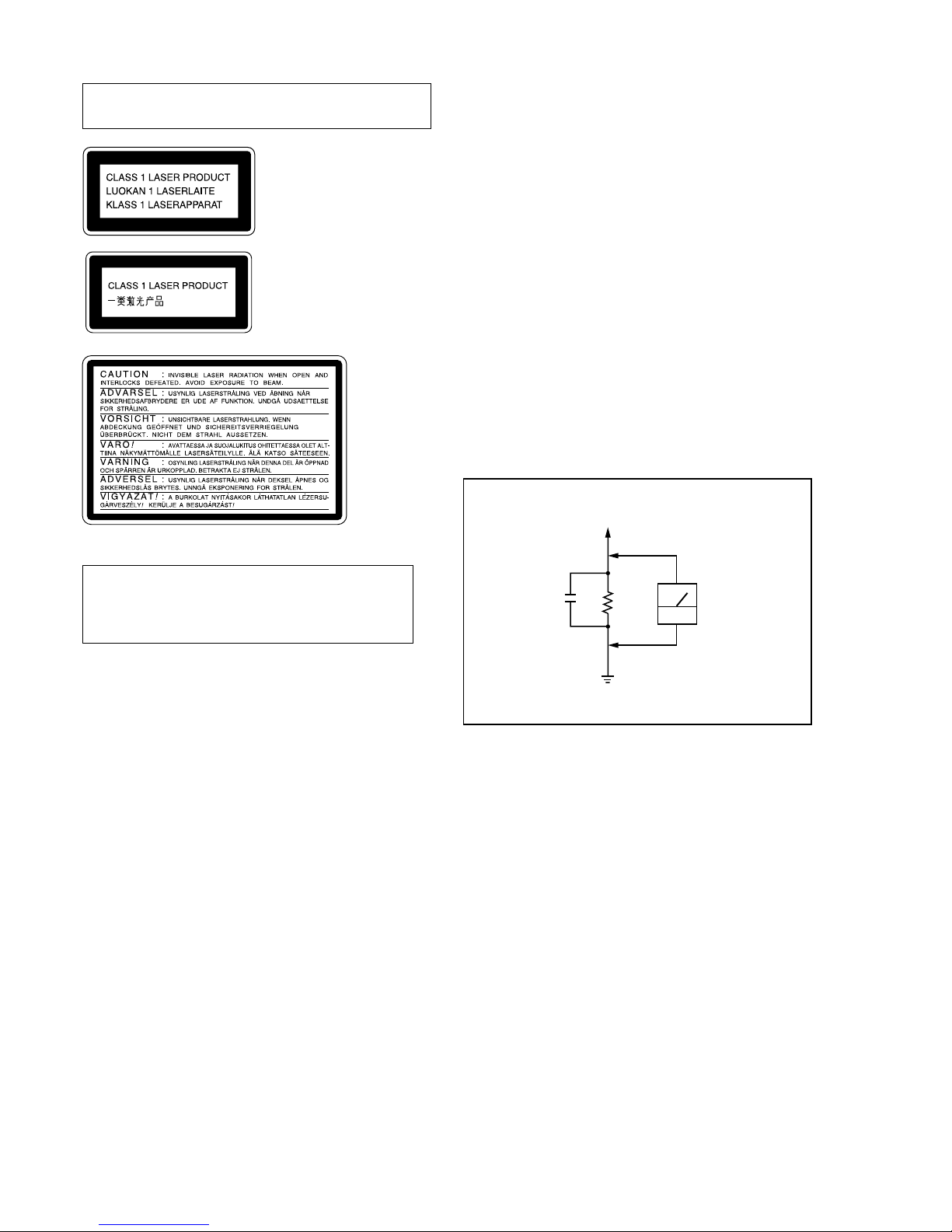
3. Measuring the voltage drop across a resistor by means of a
VOM or battery-operated AC v oltmeter . The “limit” indication
is 0.75 V, so analog meters must have an accurate low-volta ge
scale. The Simpson 250 and Sanwa SH-63Trd are e xamples of
a passive VOM that is suitable. Nearly all battery operated
digital multimeters that have a 2V AC range are suitable. (See
Fig. A)
Fig. A. Using an AC voltmeter to check AC leakage.
0.15µF
To Exposed Metal
Parts on Set
1.5kΩ
AC
voltmeter
(0.75V)
Earth Ground
CAUTION
Use of controls or adjustments or performance of procedures
other than those specified herein may result in hazardous
radiation exposure.
Notes on chip component replacement
• Never reuse a disconnected chip component.
• Notice that the minus side of a tantalum capacitor may be
damaged by heat.
Flexible Circuit Board Repairing
• Keep the temperature of soldering iron around 270˚C
during repairing.
• Do not touch the soldering iron on the same conductor of the
circuit board (within 3 times).
• Be careful not to apply force on the conductor when soldering
or unsoldering.
Laser component in this product is capable of emitting radiation
exceeding the limit for Class 1.
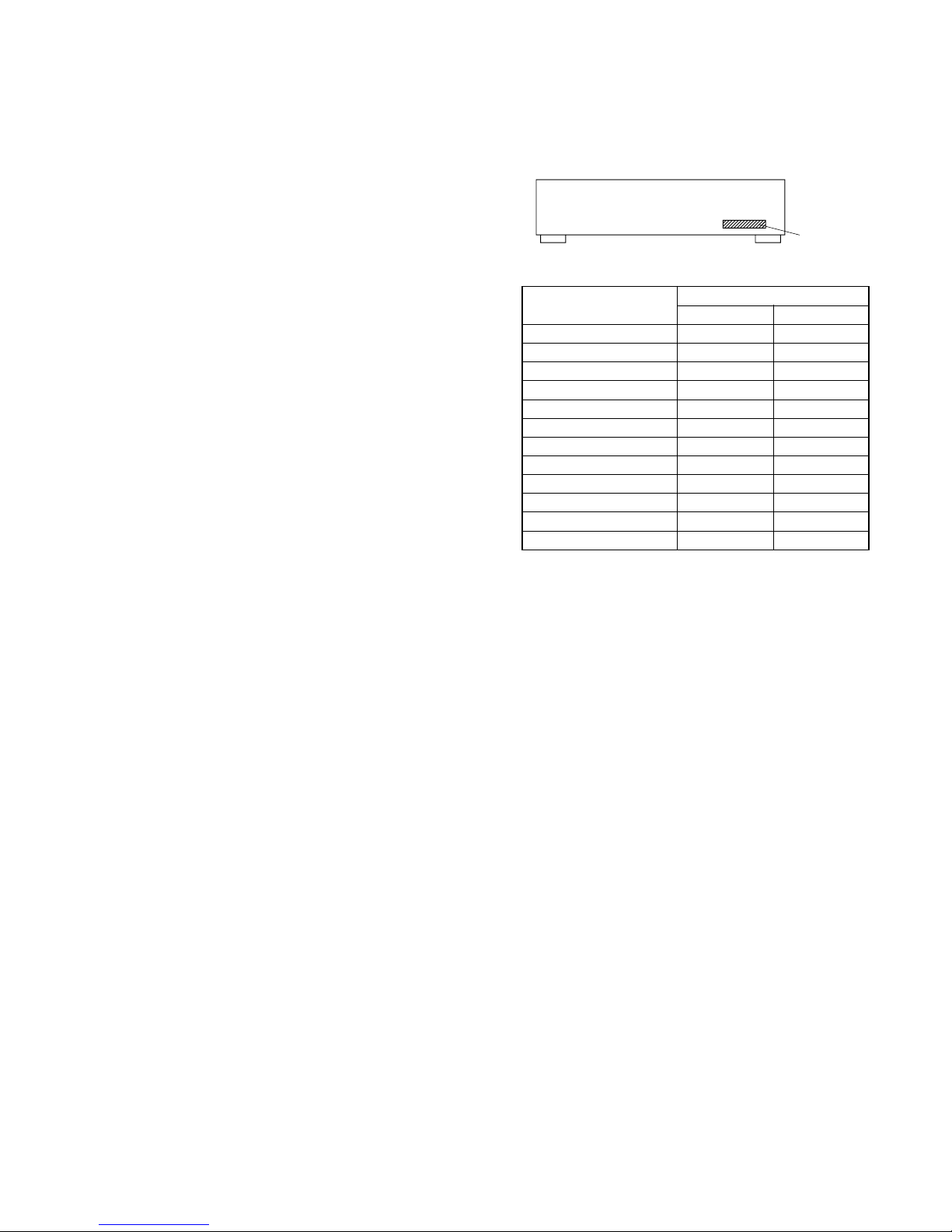
This appliance is classified as
a CLASS 1 LASER product.
The CLASS 1 LASER
PRODUCT MARKING is
located on the rear exterior.
This caution
label is located
inside the unit.
SAFETY-RELATED COMPONENT WARNING!!
COMPONENTS IDENTIFIED BY MARK 0 OR DOTTED LINE WITH
MARK 0 ON THE SCHEMATIC DIAGRAMS AND IN THE PARTS
LIST ARE CRITICAL TO SAFE OPERATION. REPLACE THESE
COMPONENTS WITH SONY PARTS WHOSE PART NUMBERS
APPEAR AS SHOWN IN THIS MANUAL OR IN SUPPLEMENTS
PUBLISHED BY SONY.
ATTENTION AU COMPOSANT AYANT RAPPORT
À LA SÉCURITÉ!
LES COMPOSANTS IDENTIFÉS PAR UNE MARQUE 0 SUR LES
DIAGRAMMES SCHÉMATIQUES ET LA LISTE DES PIÈCES SONT
CRITIQUES POUR LA SÉCURITÉ DE FONCTIONNEMENT. NE
REMPLACER CES COMPOSANTS QUE PAR DES PIÈSES SONY
DONT LES NUMÉROS SONT DONNÉS DANS CE MANUEL OU
DANS LES SUPPÉMENTS PUBLIÉS PAR SONY.
3
HCD-S500/S800
TABLE OF CONTENTS
1. SERVICING NOTE ·························································· 5
2. GENERAL ·········································································· 6
3. DISASSEMBLY ································································ 8
4. TEST MODE ···································································· 12
5. ELECTRICAL ADJUSTMENT ·································· 22
6. DIAGRAMS ······································································ 25
6-1. Block Diagrams ··························································· 26
– RF/Servo, Video Section – ······································· 26
– CPU Section – ·························································· 27
– Power Section – ························································ 28
6-2. Printed Wiring Board – RF Section – ························· 29
6-3. Schematic Diagram – RF Section – ··························· 30
6-4. Printed Wiring Board – DVD Section (1/2) – ············ 31
6-5. Printed Wiring Board – DVD Section (2/2) – ············ 32
6-6. Schematic Diagram – DVD (1/8) Section – ··············· 33
6-7. Schematic Diagram – DVD (2/8) Section – ··············· 34
6-8. Schematic Diagram – DVD (3/8) Section – ··············· 35
6-9. Schematic Diagram – DVD (4/8) Section – ··············· 36
6-10. Schematic Diagram – DVD (5/8) Section – ··············· 37
6-11. Schematic Diagram – DVD (6/8) Section – ··············· 38
6-12. Schematic Diagram – DVD (7/8) Section – ··············· 39
6-13. Schematic Diagram – DVD (8/8) Section – ··············· 40
6-14. Printed Wiring Board – AMP Section (1/2) – ············ 41
6-15. Printed Wiring Board – AMP Section (2/2) – ············ 42
6-16. Schematic Diagram – AMP Section (1/2) – ··············· 43
6-17. Schematic Diagram – AMP Section (2/2) – ··············· 44
6-18. Printed Wiring Board – I/O Section – ························ 45
6-19. Schematic Diagram – I/O Section (1/2) – ·················· 46
6-20. Schematic Diagram – I/O Section (2/2) – ·················· 47
6-21. Printed Wiring Board – Panel Section – ····················· 48
6-22. Schematic Diagram – Panel Section – ······················· 49
6-23. Printed Wiring Board – Front Section – ····················· 50
6-24. Schematic Diagram – Front Section – ························ 51
6-25. Printed Wiring Board – Power Section – ···················· 52
6-26. Printed Wiring Board – Power Section – ··················· 53
6-27. Schematic Diagram – Power Section – ······················ 54
6-28. Schematic Diagram – Loading Section – ··················· 55
6-29. Printed Wiring Board – Loading Section – ················ 55
6-30. IC Block Diagrams ······················································ 56
6-31. IC Pin Function Description ········································ 60
7. EXPLODED VIEWS
7-1. Main Section ······························································· 70
7-2. Front Panel Section ····················································· 71
7-3. Chassis Section ···························································· 72
7-4. Mechanism Deck Section (CDM55D-DVBU8) ············ 74
8. ELECTRICAL PARTS LIST ······································· 75
MODEL IDENTIFICATION
— BACK PANEL —
Part No.
•Abbreviation
E12 : 220-240V AC area in E model
E32 : 110-240V AC area in E model
Model
US, Canadian models
AEP, UK models
Mexican model
E32 model
Australian model
Malaysia, Singapore models
E12 model
Taiwan model
Argentine model
Saudi Arabia model
Hong Kong model
CIS model
PA RTS No.
DAV-S500 DAV-S800
4-234-914-0s ---------------------
4-236-491-2s 4-234-914-1s
4-234-914-2s 4-236-126-6s
4-234-914-3s ---------------------
4-234-914-4s 4-237-482-5s
4-234-914-5s ---------------------
4-234-914-6s ---------------------
4-234-914-7s 4-237-482-6s
4-234-914-8s ---------------------
4-234-914-9s 4-237-482-3s
4-237-482-0s 4-237-482-4s
4-237-482-7s 4-237-482-2s
Ver 1.3 2002.07
4
HCD-S500/S800
NOTES ON HANDLING THE OPTICAL PICK-UP BLOCK
OR BASE UNIT
The laser diode in the optical pick-up block may suffer electrostatic
break-down because of the potential difference generated by the
charged electrostatic load, etc. on clothing and the human body.
During repair, pay attention to electrostatic break-down and also
use the procedure in the printed matter which is included in the
repair parts.
The flexible board is easily damaged and should be handled with
care.
NOTES ON LASER DIODE EMISSION CHECK
The laser beam on this model is concentrated so as to be focused on
the disc reflective surface by the objective lens in the optical pickup block. Therefore, when checking the laser diode emission,
observe from more than 30 cm away from the objective lens.
LASER DIODE AND FOCUS SEARCH OPERATION
CHECK
Carry out the “S curve check” in “CD section adjustment” and check
that the S curve waveform is output several times.
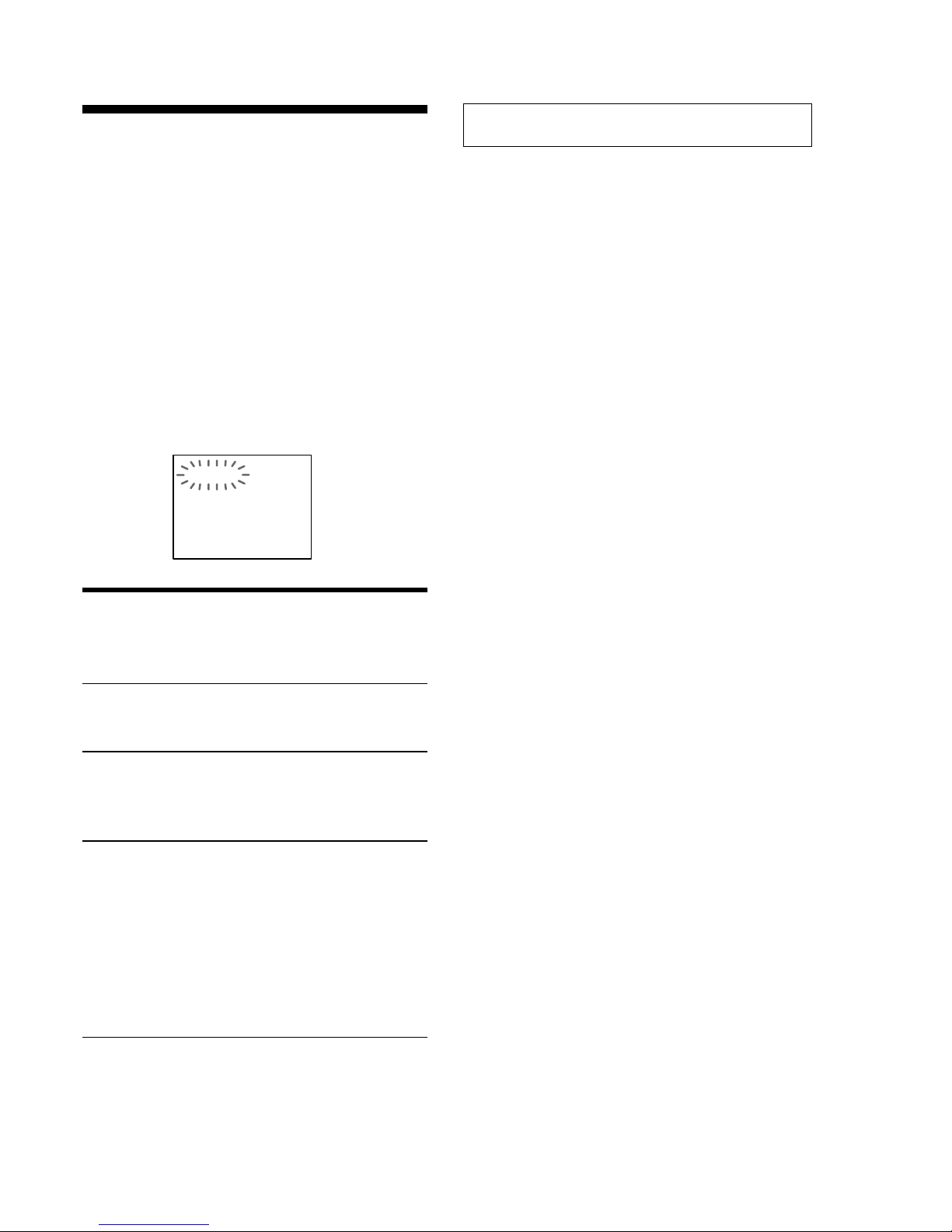
Self-diagnosis Function
(When letters/numbers appear in the
display)
When the self-diagnosis function is
activated to prevent the system from
malfunctioning. In this case a five-character
service number (e.g., C 13 00) with a
combination of a letter and digits appears on
the screen and the front panel display. Refer
to the following table.
First three
characters of
the service
number
C 13
C 31
E XX
(xx is a number)
Cause and/or Corrective
Action
The disc is dirty.
, Clean the disc with a soft
cloth (page 9).
The disc is not inserted
correctly.
, Re-insert the disc
correctly.
To prevent a malfunction, the
system has performed the selfdiagnosis function.
, Contact your nearest Sony
dealer or local authorized
Sony service facility and
give the 5-character
service number.
Example: E 61 10
C:13:00
5
HCD-S500/S800
SECTION 1
SERVICING NOTE
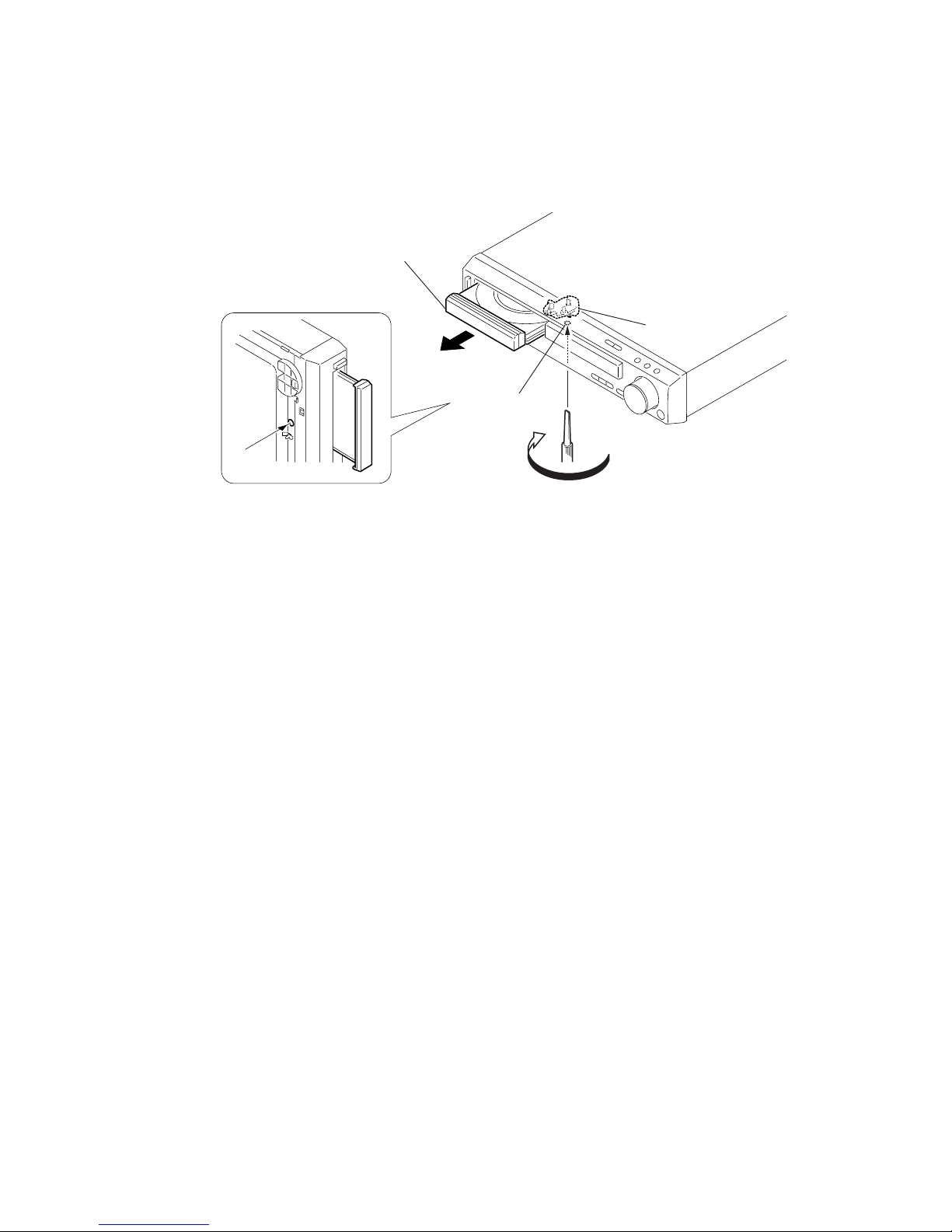
HOW TO OPEN THE DISC TRAY WHEN POWER
SWITCH TURNS OFF
When removing the disc tray, high torque is necessary to turn the
ejection cam on the bottom surface. Therefore, the screw thread is
easily damaged. To prevent this damage, turn it carefully.
1
Turn the cam in the direction of the arrow.
2
Pull-out the disc tray.
Cam
Hole of chassis
6
HCD-S500/S800
SECTION 2
GENERAL
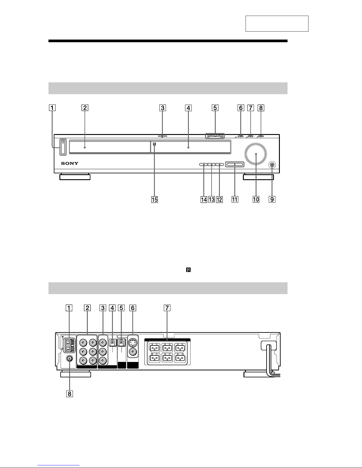
Index to Parts and Controls
For more information, refer to the pages indicated in parentheses.
Front Panel
1 POWER switch/indicator (31)
2 Disc tray (31)
A OPEN/CLOSE (31)
4 Front panel display (11)
5 ./> PREV/NEXT, PRESET +/–
(29, 32)
6 H (play) (31)
7 X (pause) (32)
8 x (stop) (31)
9 PHONES jack (31)
0 VOLUME control (31)
qa SOUND FIELD +/– (47)
qs DISPLAY (47, 60)
qd BAND (29)
qf FUNCTION (59)
qg
(remote sensor) (17)
1 AM antenna (20)
2 VIDEO 1 jacks (22)
3 VIDEO 2 jacks (22)
4 DIGITAL IN (OPTICAL) jack (23)
5 DIGITAL OUT (OPTICAL) jack
6 MONITOR OUT (VIDEO/S VIDEO)
jacks (22)
7 SPEAKER jacks (18)
8 FM 75 COAXIAL antenna jack (21)
Rear Panel
COAXIAL
VIDEO OUT
AUDIO OUT
VIDEO
IN VIDEO IN
OPTICAL
DIGITAL
IN
VIDEO
SVIDEO (DVD ONLY)
OPTICAL
(CD ONLY)
AUDIO IN
AUDIO
IN
AM
L
R
L
R
FM
75
FRONT R
FRONT L
CENTER
REAR R
REAR L
WOOFER
VIDEO 1 VIDEO 2
SPEAKER
MONITOR
OUT
DIGITAL
OUT
3
This section is extracted
from instruction manual.

7
HCD-S500/S800
Remote
123
456
7
>
10
10/0
89
1 TV "/1 (on/standby) (58)
2 OPEN/CLOSE (31)
3 NAME (61)
4 STEREO/MONO (60)
5 MEMORY (29)
6 CLEAR (35)
7 PLAY MODE (35)
8 AUDIO (45)
9 ANGLE (50)
0 SUBTITLE (51)
qa VOL +/– (60)
qs ./> PREV/NEXT, TV/PRESET
+/– (29, 32)
qd H PLAY/SELECT (31)
qf TITLE (33)
qg DVD DISPLAY (38)
qh C/X/x/c/ENTER (25)
qj DVD SETUP (54)
qk "/1 (on/standby) (31)
ql DIMMER (28)
w; TV/VIDEO (58)
wa REPEAT (38)
ws MUTING (32)
wd TIME (42)
wf FUNCTION (59)
wg BAND (29)
wh Number buttons (33)
wj SOUND FIELD (47)
wk DISPLAY (47, 60)
wl ENTER
e; CONTROL DVD/TV switch (58)
ea m/M/
/ SLOW, TUNING +/–
(29, 39)
es x STOP (31)
ed X PAUSE (32)
ef DVD MENU (34)
eg O RETURN (34)
eh AMP MENU (25)
Note
This remote control glows in the dark. However,
before glowing, the remote must be exposed to light
for awhile.
8
HCD-S500/S800
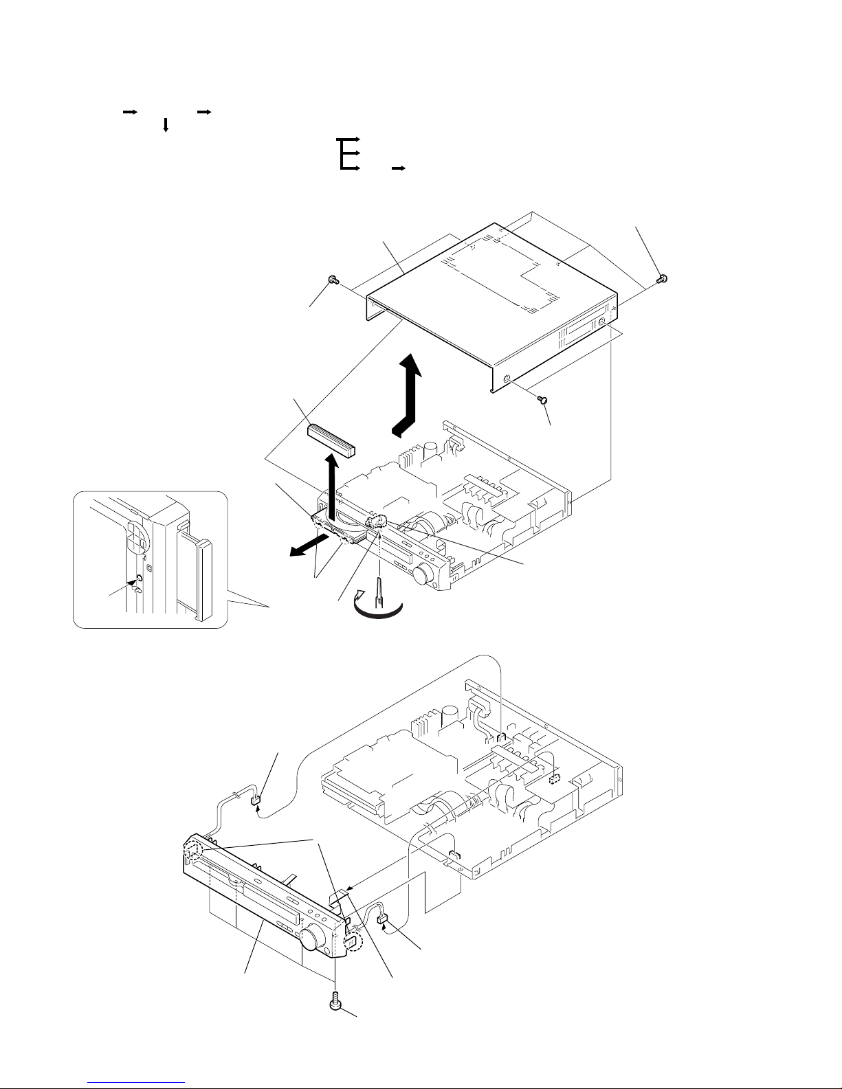
SECTION 3
DISASSEMBLY
Note: Follow the disassembly procedure in the numerical order given.
1. CASE (TOP), DVD LID, LID WINDOW SUB ASSEMBLY
2. FRONT PANEL SECTION
2
Two case screws
1
Two case
screws
Cam
Hole of chassis
5
Turn the cam in the direction of the arrow.
7
Two claws
8
DVD lid,
Lid window sub assembly
6
Pull-out the disc tray.
4
Case (Top)
3
Four screws
(+BVTP 3 × 8
)
1
Connector (CN309)
3
Connector (CN902)
2
Flexible flat cable (15 core)
(CN005)
5
Two claws
4
Four screws
(+BVTP 3
×
8)
6
Front panel section
RF-240 board
Tray Optical pick-up (KHM-240AAA)
Front panel sectionCase (Top)Set
Loading board, Loading motor assembly (M901
)
DVD mechanism deck (CDM550-DVBU8)
• The equipment can be removed using the following procedure.
9
HCD-S500/S800
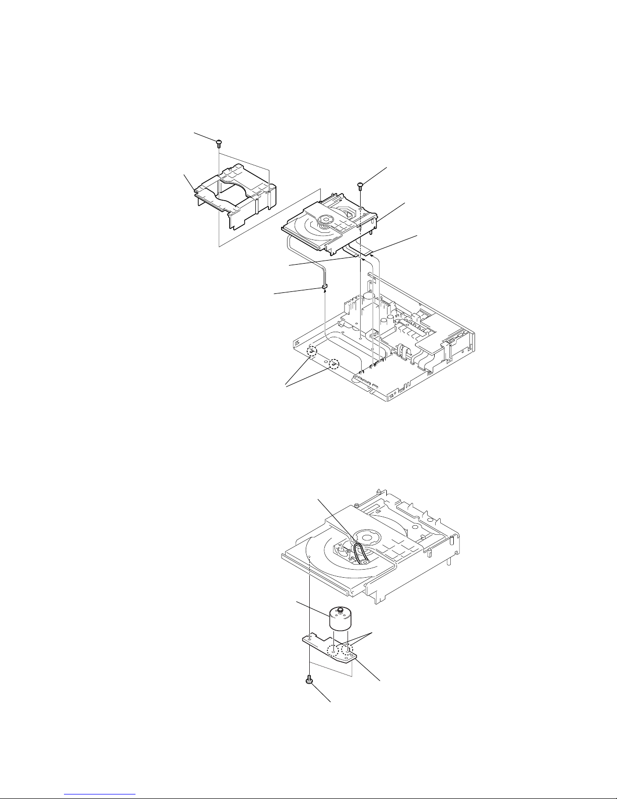
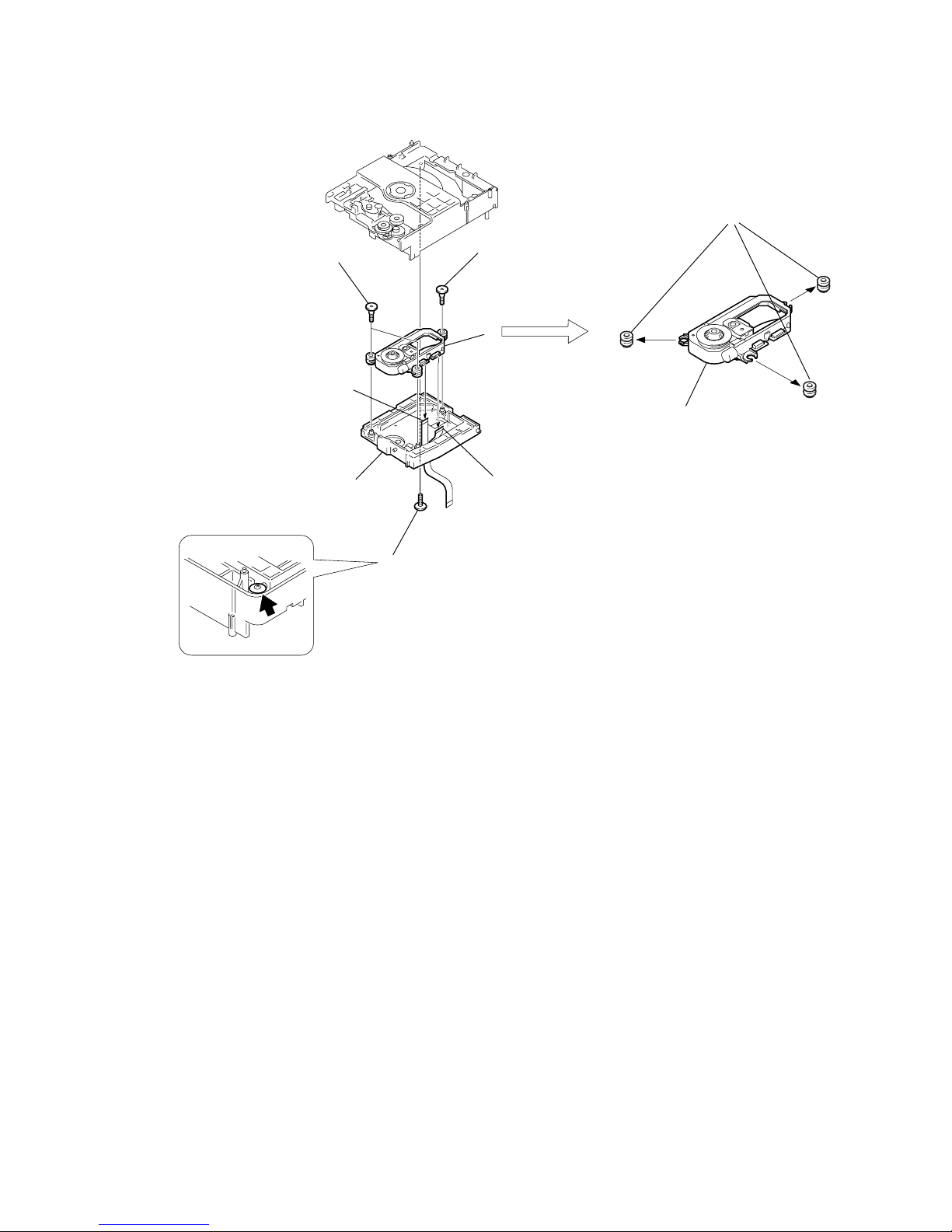
4. LOADING BOARD, LOADING MOTOR ASSEMBLY (M901)
3. DVD MECHANISM DECK (CDM55D-DVBU8)
3
Connector (CN402)
4
Flexible flat cable (9 core)
(CN009)
2
MD cover
5
Flexible flat cable (25 core
)
(CN010)
7
Two claws
1
Two screws
(DIA. 2.6
×
8)
6
Screw
(+BVTP 3
×
8)
8
Mechanism deck
(CDM55D-DVBU8)
2
Two screws
(+BTP 2.6
×
6)
5
Loading board
3
Two solderings
4
Motor (LD) assy (M901)
1
Remove the belt
(CDM55)
10
HCD-S500/S800
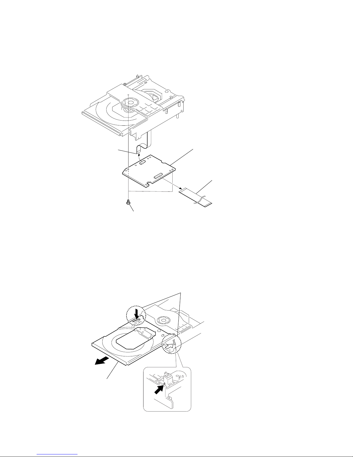
6. TRAY
5. RF-240 BOARD
3
Two screws
(+BTP 2.6 × 6)
4
RF-240 board
1
Flexible flat cable (25 core
)
(CN002)
2
Flexible flat cable (26P)
(CN001)
1
While pushing the two protrusions, release the two claws fixing the tray
and pull out the tray in the direction of the arrow
A
. (Be carefull of the two claws.
)
2
Tray
A
11
HCD-S500/S800
7. OPTICAL PICK-UP (KHM-240AAA)
1
Floating screw (+PTPWHM 2.6)
2
Flexible flat cable
(9 core)
3
Flexible flat cable
(26 core)
4
Step screw (L)
8
Three insulators
9
Optical pick-up
(KHM-240AAA)
5
Two step screws (M)
6
Holder (KHM-240)
7
12
HCD-S500/S800
4-1. VERSION DISPLAY MODE
Procedure:
1. Press the A button on the main unit or 1 button on the
remote commander to turn the set on.
2. Press three buttons of FUNCTION , . PREV and A
simultaneously for two seconds.
3. The message “VER. 1. ** ” is displayed for a moment.
4-2. JOG TEST MODE
Procedure:
1. Press the A button on the main unit or 1 button on the
remote commander to turn the set on.
2. Press three buttons of BAND , x and A simultaneously.
3. The fluorescent indicator displays “JOG 0”. The value “JOG
0” increases like +1, +2, +3... if rotating the VOLUME knob
clockwisw,or it decreases like –1, –2, –3,.... if rotating counter-
clockwise.
4. T o e xit from this mode, press the POWER button to turn the
set off.
4-3. KEY TEST MODE
Procedure:
1. Press the A button on the main unit or 1 button on the
remote commander to turn the set on.
2. Press three buttons of DISPLAY , x and A simultaneously.
3. The message “KEY NUM 0” is displayed and “0” blinks.
4. Each time a button is pressed, “KEY NUM 0” value increases.
However, once a button is pressed, it is no longer taken into
account.
5. When all buttons are pressed, “KEY NUM 11” appears and
the number blinking is stopped.
6. T o e xit from this mode, press the POWER button to turn the
set off.
4-4. DISPLAY TEST MODE
Procedure:
1. Press the A button on the main unit or 1 button on the
remote commander to turn the set on.
2. Press three buttons of BAND , X and A simultaneously.
3. All segments are turned on.
4. When the NEXT > button is pressed, the display will light
up as follows.
5. Press the NEXT > button, confirm the display.
6. Press the NEXT > button, all segments are turned off.
7. Every pressing of the NEXT > button turns on each
segments in the same order.
8. T o e xit from this mode, press the POWER button to turn the
set off.
4-5. OSD TEST MODE
Procedure:
1. Press the A button on the main unit or 1 button on the
remote commander to turn the set on.
2. Set the FUNCTION to DVD.
3. While pressing two buttons of DISPLAY and
x simultaneously, turn the VOLUME knob clockwise.
4. The Test Mode Menu is displayed on the TV screen.
5. To execute each function, select the number on the remote
commander.
6. See the following section for explanation in detail.
7. T o exit fr om this mode, press the POWER button to turn the
set off.
4-6. DISC TRAY LOCK
Procedure:
1. Press the A button on the main unit or 1 button on the
remote commander to turn the set on.
2. Press two buttons of DISPLAY and . PREV
simultaneously for two seconds.
3. The message “LOCKED” is displayed and the tray is locked.
(Even if exiting from this mode, the tray is still locked.)
4. Press two buttons of DISPLAY and . PREV
simultaneously for two seconds again.
5. The message “UNLOCKED” is displayed and the tray is
unlocked.
6. T o exit fr om this mode, press the POWER button to turn the
set off.
4-7. GENERAL DESCRIPTION
The T est Mode allows you to make diagnosis and adjustment easil y
using the remote commander and monitor TV. The instructions,
diagnostic results, etc. are given on the on-screen display (OSD).
4-8. STARTING TEST MODE
Set the FUNCTION to DVD with the main unit power on. Next,
while pushing the x button and the [DISPLAY] button on the main
unit at the same time, turn the VOLUME knob to the right to start
Test Mode and display the menu sho wn below on the TV screen. At
the bottom of the menu screen, the model name and revision number
are displayed.
To execute each function, select the desired menu and press its
number on the remote commander. To exit from Test Mode, press
the [POWER] button.
Test Mode Menu
0. Syscon Diagnosis
1. Drive Auto Adjustment
2. Drive Manual Operation
3. Mecha Aging
4. Emergency History
5. Version Information
6. Video Level Adjustment
Exit: POWER Key
_
Model : HCX-1030_xx
Revision: 1.xxx
SECTION 4
TEST MODE
ALL 1 DISCS AUTO TITLE TRACK CHAPTER INDEX HTUNED M MONO ST S
dB REPEAT 1
kHz PROGRAM
MHz SHUFFLE
PRO LOGIC
DIGITAL FM AM
NTSC PBC ANGLE
D
D
D
D
dts
PCM
ALL 1 DISCS AUTO TITLE TRACK CHAPTER INDEX HTUNED M MONO ST S
dB REPEAT 1
kHz PROGRAM
MHz SHUFFLE
PRO LOGIC
DIGITAL FM AM
NTSC PBC ANGLE
D
D
D
D
dts
PCM

13
HCD-S500/S800
4-9. SYSCON DIAGNOSIS
The same contents as board detail check by serial interface can be
checked from the remote commander.
On the Test Mode Menu screen, press [0] key on the remote
commander, and the following check menu will be displayed.
### Syscon Diagnosis ###
Check Menu
0. Quit
1. All
2. Version
3. Peripheral
4. Servo
5. Supply
6. AV Decoder
7. Video
8. Audio
9. DSD Decoder
_
0. Quit
Quit the Syscon Diagnosis and return to the Test Mode Menu.
1. All
All items continuous check
This menu checks all diagnostic items continuously. Normally, all
items are checked successively one after another automatically
unless an error is found, but at a certain item that requires judgment
through a visual check to the result, the following screen is displayed
for the key entry.
### Syscon Diagnosis ###
Diag All Check
No. 2 Version
2-3. ROM Check Sum
Check Sum = 2005
Press NEXT Key to Continue
Press PREV Key to Repeat
_
For the ROM Check, the check sum calculated by the Syscon is
output, and therefore you must compare it with the specified value
for confirmation.
Following the message, press [NEXT] key to go to the ne xt item, or
[PREV] key to repeat the same check again. To quit the diagnosis
and return to the Check Menu screen, press x or [ENTER] key. If
an error occurred, the diagnosis is suspended and the error code is
displayed as shown below.
### Syscon Diagnosis ###
3-3. EEPROM Check
Error 03: EEPROM Write/Reed N
Address : 00000001
Write Data : 2492
Read Data : 2490
Press NEXT Key to Continue
Press PREV Key to Repeat
_
Press x key to quit the diagnosis, or [PREV] key to repeat the
same item where an error occurred, or
[NEXT] key to continue the
check from the item next to faulty item.
Selecting 2 and subsequent items calls the submenu screen of each
item.
For example, if “5. Supply” is selected, the following submenu will
be displayed.
### Syscon Diagnosis ###
Check Menu
No. 5 Supply
0. Quit
1. All
2. ARP Register Check
3. ARP to RAM Data Bus
4. ARP to RAM Address Bus
5. ARP RAM Check
_
0. Quit
Quit the submenu and return to the main menu.
1. All
All submenu items continuous check
This menu checks 2 and subsequent items successively . At the item
where visual check is required for judgment or an error occurred,
the checking is suspended and the message is output for key entry.
Normally, all items are checked successively one after another
automatically unless an error is found.
Selecting 2 and subsequent items executes respective menus and
outputs the results.
For the contents of each submenu, see “Check Items List”.
General Description of Checking Method
2. Version
(2-2) Revision
ROM revision number is displayed.Error: Not detected.
The revision number defined in the source file of R OM (At
the beginning of mass production, the Flash ROM of IC107
is used, but midway it is replaced by the IC108 OTP R OM.
IC107 or IC108) is displayed with four digits.
Below IC107 are all IC107 or IC108.
(2-3) ROM Check Sum
Check sum is calculated.
Error: Not detected.
The 8-bit data are added at addresses 0x000F0000 ~
0x002EFFFF of ROM (IC107) and the result is displayed
with 4-digit hexadecimal number. Error is not detected.
Compare the result with the specified value.
(2-4) Model Type
Model code is displayed.
Error: Not detected.
The model code read from EEPROM (IC101) is displayed
with 2-digit hexadecimal number.
(2-5) Region
Region code is displayed.
Error: Not detected.
The region code determined from the model code is displayed.

14
HCD-S500/S800
3. Peripheral
(3-2) EEPROM Check
Data write → read, and accord check
Error 03: EEPROM write/read discord
Data 0x9249, 0x2942, 0x4294 are written to addresses
0x00~0xFF of EEPROM (IC101), then read and checked.
Before writing, the data are saved, then after checking, they
are written to restore the contents of EEPROM.
4. Servo
(4-2) Servo DSP Check
Data write → read, and accord check
Error 12: Read data discord
Data 0x9249, 0x2942, 0x4294 are written to the address
0x602 of RAM in the Servo DSP (IC302), then read and
checked.
(4-3) DSP Driver Test
Test signal data → DSP Driver
Error: Not detected.
Caution: Do not conduct this test with a mechanical deck
connected.
The maximum voltage is applied to the Servo Driver IC
(IC401, IC802). If mechanical deck is connected, the motor and optics could be damaged. Disconnect mechanical
deck following the output message, then enter specified 4or 5-digit number from the remote commander, and press
the [ENTER]. The test is conducted only when the input
data accord. Check the output level, then press the [NEXT]
to finish the test.
This test is skipped if “All” is selected.
Supplement: How to disconnect mechanical deck
Disconnect flat cables connected to the CN009 and CN010
of MB-82/85 board. Also, disconnect harness from the
CN402.
5. Supply
Caution: Do not conduct this check with a mechanical deck
connected.
An access is made to the stream supply and servo control
IC (IC302) and external RAM (IC303) using check data.
If mechanical deck is connected, the motor and optics
could be damaged. This check is also executed by the “All”
menu item.
Supplement: How to disconnect mechanical deck
Disconnect flat cables connected to the CN009 and
CN010 of DVD board. Also, disconnect harness from
the CN402.
(5-2) ARP Register Check
Data write → read, and accord check
Error 08: ARP register write, and read data discord
Data 0x00 to 0xFF are written to the TMAX register (address 0xC6) in ARP (IC302), then they are read and check ed.
(5-3) ARP to RAM Data Bus
Data write → read, and accord check
Error 09: ARP ←→ RAM data bus error
Data 0x0001 to 0x8000 where one bit each is set to 1 are
written to the address 0 of RAM (IC303) connected to the
ARP (IC302) through the bus, then they are read and
checked. In case of discord, written bit pattern and read
data are displayed. If data where multiple bits are 1 are
read, the bits concerned may touch each other. Further, if
data where certain bit is always 1 or 0 regardless of written
data, the line could be disconnected or shorted.
(5-4) ARP to RAM Address Bus
Data write → other address read discord check
Error 10: ARP → RAM address bus error
Caution: Address and data display in case of an error is
different from the display of other diagnosis (de-
scribed later).
Before starting the test, all addresses of RAM (IC303) are
cleared to 0x0000.
First, 0xA55A is written to the address 0x00000, and the
address data are read and checked from addresses 0x00001
to 0x80000 while shifting 1 bit each. Next, the data at that
address is cleared, and it is written to the address 0x00001,
and read and checked in the same manner. This check is
repeated up to the address 0x80000 while shifting the address data by 1 bit each.
If data other than 0 is read at the addresses except written
address, an error is given because all addresses were already cleared to 0. In this check, the error display pattern is
different from that of other diagnosis; read data, written
address, and read address are displayed in this order. Ho wever, the message uses same template, and accordingly exchange Address and Data when reading. The follo wing display, for example,
### Syscon Diagnosis ###
5-4. ARP to RAM Address Bus
Error 10: ARP - RAM Address B
Address : 0000A55A
Write Data : 00000000
Read Data : 00080000
Press NEXT Key to Continue
Press PREV Key to Repeat
_
shows the data 0xA55A was read from address 0x00080000
though it was written to the address 0x00000000. This implies that these addresses are in the form of shadow. Also,
if the read data is not 0xA55A, another error will be present.
(5-5) ARP RAM Check
Data write → read, and accord check
Error 11: ARP RAM read data discord
The program code data stored in ROM are copied to all
areas of RAM (IC303) connected to the ARP (IC302)
through the bus, then they are read and checked if they accord. If the detail check was selected initially, the data are
written to all areas and read, then the same test is conducted
once again with the data where all bits are inverted between
1 and 0. If discord is detected, faulty address, written data,
and read data are displayed following the error code 11,
and the test is suspended.

15
HCD-S500/S800
6. AV Decoder
(6-2) 1930 RAM
Data write → read, and accord check
Error 13: AVD RAM read data discord
The program code data stored in ROM (IC107 or IC108)
are copied to all areas oo»RAM (IC504, IC505) connected
to the AVD (IC503) through the bus, then they are read and
checked if they accord. Further, the same test is conducted
once again with the data where all bits are inverted between
1 and 0. If discord is detected, faulty address, written data,
and read data are displayed following the error code 13,
and the test is suspended.
(6-3) 1930 SP
ROM → AVD RAM → Video OUT
Error: Not detected.
The data including sub picture streams in ROM (IC107 or
IC108) are transferred to the RAM (IC504, IC505) in AVD
(IC503), and output as video signals from the AVD (IC503).
They are output from all video terminals (Composite, Y/C).
7. Video
(7-2) Color Bar
AVD color bar command write → Video OUT
Error: Not detected.
The command is transferred to the AVD, and the color bar
signals are output from video terminals.
They are output from all video terminals (Composite, Y/C).
(7-3) Composit Out
(7-4) Y/C Out
(7-6) Component Out
8. Audio
(8-2) ARP → 1930
Error 14 : ARP → 1930 video NG
15 : ARP → 1930 audio NG
(8-3) Test T one
All channels
2ch Left
2ch Right
Front Left
Front Right
Rear Left
Rear Right
Center
Sub Woof er
9. DSD Decoder
(9-2) 2752 ID Chack
(9-3) 2752 RAM Check
Check Items List
2) Version
(2-2) Revision
(2-3) ROM Check Sum
(2-4) Model Type
(2-5) Region
3) Peripheral
(3-2) EEPROM Check
4) Servo
(4-2) Servo DSP Check
(4-3) DSP Driver Test
5) Supply
(5-2) ARP Register Check
(5-3) ARP to RAM Data Bus
(5-4) ARP to RAM Address Bus
(5-5) ARP RAM Check
6) AV Decoder
(6-2) 1930 RAM
(6-3) 1930 SP
7) Video
(7-2) Color Bar
(7-3) Composit Out
(7-4) Y/C Out
(7-6) Component Out
8) Audio
(8-2) ARP → 1930
(8-3) Test Tone
9) DSD Decoder
(9-2) 2752 ID Check
(9-3) 2752 RAM Check
Error Codes List
00: Error not detected
01: RAM write/read data discord
02: Gate array NG
03: EEPROM NG
08: ARP register read data discord
09: ARP ←→ RAM data bus error
10: ARP ←→ RAM address bus error
11: ARP RAM read data discord
12: Servo DSP NG
13: 1930 SDRAM NG
14: ARP → 1930 video NG
15: ARP → 1930 audio NG
16: 1910 UCODE download NG
17: System call error (function not supported)
18: System call error (parameter error)
19: System call error (illegal ID number)
20: System call error (time out)
90: Error occurred
91: User verification NG
92: Diagnosis cancelled

16
HCD-S500/S800
4-10. DRIVE AUTO ADJUSTMENT
On the Test Mode Menu screen, press [1] key on the remote
commander, and the dri ve auto adjustment menu will be displayed.
## Drive Auto Adjustment ##
Adjustment Menu
0. ALL
1. DVD-SL
2. CD
3. DVD-DL
4. LCD
Exit: RETURN
Normally, [0] is selected to adjust DVD (single layer), CD, DVD
(dual layer), and SACD in this order. But, individual items can be
adjusted for the case where adjustment is suspended due to an error.
In this mode, the adjustment can be made easily through the
operation following the message displayed on the screen.
The disc used for adjustment must be the one specified for
adjustment. However, for SACD disc, use the player with initial
data if the disc is not available.
0. ALL
Select [0] and press [ENTER] key, and the servo set data in
EEPROM will be initialized. Then, 1. D VD-SL disc, 2. CD disc , 3.
DVD-DL disc, and 4. SACD disc are adjusted in this order. Each
time one disc was adjusted, it is ejected. Replace it with the specified
disc following the message. Though the message to confirm whether
discs other than SACD disc are adjusted is not displayed, you can
finish the adjustment if pressing the x button. During adjustment
of each disc, the measurement for disc type judgment is made. As
automatic adjustment does not judge the disc type unlike
conventional models, take care not to insert wrong type discs. Also,
do not give a shock during adjustment.
1. DVD-SL (single layer)
Select [1], insert DVD single layer disc, and press [ENTER] key,
and the adjustment will be made through the following steps, then
adjusted values will be written to the EEPROM.
DVD Single Layer Disc Adjustment Steps
1. SLED TILT Reset
2. Disc Check Memory SL
3. Wait 300 msec
4. Set Disc Type SL
5. LD ON
6. Spdl Start
7. Wait 1 sec
8. Focus Servo ON 0
9. Auto Track Offset Adjust
10. CLVA ON
11. Wait 500 msec
12. Tracking ON
13. Wait 1 sec
14. Sled ON
15. Check CLV Lock
16. Auto LFO Adjust
17. Auto Focus Offset Adjust
18. Auto Tilt Position Adjust
19. Auto Focus Gain Adjust
20. Auto Focus Offset Adjust
21. EQ Boost Adjust
22. Auto LFO Adjust
23. Auto Track Gain Adjust, Search Check
24. 32Tj Fwd
25. 32Tj Rev
26. 500Tj Fwd
27. 500Tj Rev
28. All Servo Stop
29. Eep Copy Loop Filter Offset

17
HCD-S500/S800
2. CD
Select [2], insert CD disc, and press [ENTER] key, and the
adjustment will be made through the following steps, then adjusted
values will be written to the EEPROM.
CD Adjustment Steps
1. Sled Tilt Rest
2. Disc Check Memory CD
3. Wait 500 msec
4. Set Disc Type CD
5. LD ON
6. Spdl Start
7. Wait 500 msec
8. Focus Servo ON 0
9. Auto Track Offset Adjust
10. CLVA ON
11. Wait 500 msec
12. Tracking ON
13. (TC Display Start)
14. Wait 1 sec
15. Jitter Display Start
16. Sled ON
17. Check CLV ON
18. Auto LFO Adjust
19. Auto Focus Offset Adjust
20.
21. Auto Focus Gain Adjust
22. Auto Focus Offset Adjust
23. Eq Boost Adjust
24. Auto LFO Adjust
25. Auto Track Gain Adjust, Search Check
26. 32Tj Fwd
27. 32Tj Rev
28. 500Tj Fwd
29. 500Tj Rev
30. All Servo Stop
3. DVD-DL (dual layer)
Select [3], insert D VD dual layer disc, and press [ENTER] key, and
the adjustment will be made through the following steps, then
adjusted values will be written to the EEPROM.
DVD Dual Layer Disc Adjustment Steps
1. Sled Tilt Reset
2. Disc Check Memory DL
3. Wait 500 msec
4. Set Disc Type DL
5. LD ON
6. Spdl Start
7. Wait 1 sec, Layer 1 Adjust
8. Focus Servo ON 0
9. Auto Track Offset Adjust
10. Clva ON
11. Wait 500 msec
12. Tracking ON
13. Wait 500 msec
14. Sled ON
15. Check CLV Lock
16. Auto Loop Filter Offset Auto Focus Adjust
17.
18. Auto Focus Gain Adjust
19. Auto Focus Offset Adjust
20. Eq Boost Adjust
21. Auto Loop Filter Offset
22. Auto Track Gain Adjust, Search Check
23. 32Tj Fwd
24. 32Tj Rev
25. 500Tj Fwd
26. 500Tj Rev, Layer 0 Adjust
27. Fj (L1 -> L0)
28. Auto Track Offset Adjust L0
29. Clva ON
30. Wait 500 msec
31. Tracking ON
32. Wait 500 msec
33. Sled ON
34. Check CLV Lock
35. Auto Focus Filter Offset
36. Auto Focus Adjust
37.
38. Auto Focus Gain Adjust
39. Auto Focus Offset Adjust
40. Eq Boost Adjust
41. Auto Loop Filter Offset
42. Auto Track Gain Adjust, Search Check
43. 32Tj Fwd
44. 32Tj Rev
45. 500Tj fwd
46. 500Tj Rev, Layer Jump Check
47. Lj (L0 -> L1)
48. Lj (L1 -> L0)
49. All Servo Stop

18
HCD-S500/S800
4. LCD
Select [4], insert SACD disc, and press [ENTER] key, and the
adjustment will be made through the following steps, then adjusted
values will be written to the EEPROM. However, if SACD disc is
not available, use the player with initial data, skipping the SACD
adjustment. In this case, you can finish the adjustment if pressing
the x button.
SACD Adjustment Steps
1. Sled Tilt Reset
2. Set Disc Type CD
3. LD ON
4. Spdl Start
5. Wait 500 msec
6. Focus Servo ON 0
7. Auto track Offset Adjust
8.
9. CLVA ON
10. Wait 500 msec
11. Tracking ON
12. Wait 1 sec
13. Sled ON
14. Check CLV ON
15. Auto Focus Offset Adjust
17.
18. Auto Focus Gain Adjust
19. Auto Focus Offset Adjust
20. Eq Boost Adjust
21. Auto LFO Adjust
22. Auto Track Gain Adjust
23. 32Tj Fwd
24. 32Tj Rev
25. 500Tj Fwd
26. 500Tj Rev
27. All Servo Stop */
4-11. DRIVE MANUAL OPERATION
On the T est Mode Menu screen, select [2], and the manual operation
menu will be displayed. For the manual operation, each servo on/
off control and adjustment can be executed manually.
## Drive Manual Operation ##
Operation Menu
1. Disc type
2. Servo Control
3. Track/Layer Jump
4. Manual Adjustment
5. Auto Adjustment
6. Memory Check
7. Sacd Water Mark
0. Disc Check Memory
_
Exit: Return
In using the manual operation menu, take care of the following
points. These commands do not provide protection, thus requiring
correct operation. The sector address or time code field is displayed
when a disc is loaded.
1. Set correctly the disc type to be used on the Disc Type
screen.
The disc type must be set after a disc was loaded.
The set disc type is cleared when the tray is opened.
2. After power ON, if the Drive Manual Operation was
selected, first perform “Reset SLED TILT” by opening 1.
Disc T ype screen.
3. In case of an alarm, immediately press the x button to
stop the servo operation, and turn the power OFF.
Basic operation (controllable from front panel or remote
commander)
[POWER] Power OFF
x Servo stop
[OPEN/CLOSE] Stop+Eject/Loading
[RETURN] Return to Operation Menu or Test Mode
Menu
[NEXT], [PREV] Transition between sub modes of menu
[1] to [9], [0] Selection of menu items
Cursor UP/DOWN Increase/Decrease in manually adjusted
value

19
HCD-S500/S800
0. Disc Check Memory
Disc Check
1. SL Disc Check
2. CD Disc Check
3. DL Disc Check
0. Reset SLED TILT
_
On this screen, the mirror time is measured to judge the disc and it
is written to the EEPROM. First load DVD SL disc and press [1],
next load CD disc and press [2], and finally load D VD DL disc and
press [3].
The adjustment must be executed more than once after default data
were written. External vibration or shock to the player must not be
given. Reference value for D VD is from 10 to 20, and for CD, from
28 to 4F.
Check that the value of CD is larger than that of DVD.
When those values are beyond a range perform this adjustment again.
From this screen, you can go to another mode by pressing [NEXT]
or [PREV] key, but you cannot enter this mode from another mode.
You can enter this mode from the Operation Menu screen only.
1. Disc Type
Disc Type
1. Disc Type Auto Check
2. DVD SL 12 cm
3. DVD DL 12 cm
4. CD 12cm
5. LCD 12 cm
6. DVD SL 8 cm
7. DVD DL 8 cm
8. CD 8 cm
9. LCD 8 cm
0. Reset SLED TILT
-- SA. ------ SI. -- EMG. 00
DVD SL12cm
On this screen, select the disc type. T o select the disc type, press the
number of the loaded disc. The selected disc type is displayed at the
bottom. Selecting [1] automatically selects and displays the disc
type. In case of wrong display, retry “Disc Check Memory”. Also,
opening the tray causes the set disc type to be cleared. In this case,
set the disc type again after loading.
In performing manual operation, the disc type must be set.
Once the disc type has been selected, the sector address or time
code display field will appear as shown below. These values are
displayed when PLL is locked.
Disc Type
1. Disc Type Auto Check
2. DVD SL 12 cm
3. DVD DL 12 cm
4. CD 12cm
5. LCD 12 cm
6. DVD SL 8 cm
7. DVD DL 8 cm
8. CD 8 cm
9. LCD 8 cm
0. Reset SLED TILT
SA. SI. EMG. 00
DVD SL 12 cm
Display when DVD SL 12cm disc was selected
Disc Type
1. Disc Type Auto Check
2. DVD SL 12 cm
3. DVD DL 12 cm
4. CD 12cm
5. LCD 12 cm
6. DVD SL 8 cm
7. DVD DL 8 cm
8. CD 8 cm
9. LCD 8 cm
0. Reset SLED TILT
TC. : : EMG. 00
CD 12 cm
Display when CD 12cm disc was selected
[0] Reset SLED TIL T Reset the Sled and Tilt to initial position.
[1] Disk Type Check Judge automatically the loaded disc. As
the judged result is displayed at the
bottom of screen, make sure that it is
correct.
If Disc Check Memory menu has not
been executed after EEPROM default
setting, the disc type cannot be judged.
In this case, return to the initial menu
and make a check for three types of discs
(SL, DL, CD).
[2] to [9] Select the loaded disc. The adjusted
value is written to the address of selected
disc. No further entry is necessary if [1]
was selected.
2. Servo Control
Servo Control
1. LD Off R.Sled FWD
2. SP Off L.Sled REV
3. Focus Off
4. TRK. Off
5. Sled Off
6. CLVA Off
7. FCS. Srch Off
0. Reset SLED TILT
SA. SI. EMG. 00
DVD SL 12 cm
On this screen, the servo on/off control necessary for replay is
executed. Normally, turn on each servo from 1 sequentially and
when CLVA is turned on, the usual trace mode becomes active. In
the trace mode, DVD sector address or CD time code is displayed.
This is not displayed where the spindle is not locked.
The spindle could run overriding the control if the spindle system is
faulty or RF is not present. In such a case, do not operate CLVA.

20
HCD-S500/S800
[0] Reset SLED TIL T Reset the Sled and Tilt to initial position.
[1] LD Turn ON/OFF the laser.
[2] SP Turn ON/OFF the spindle.
[3] Focus Search the focus and turn on the focus.
[4] TRK Turn ON/OFF the tracking servo.
[5] Sled Turn ON/OFF the sled servo.
[6] CLVA Turn ON/OFF normal servo of spindle
servo.
[7] FCS. Srch Apply same voltage as that of focus
search to the focus drive to check the
focus drive system.
→ Sled FWD Move the sled outward. Perform this
operation with the tracking servo turned
off.
← Sled REV Move the sled inward. Perform this
operation with the tracking servo turned
off.
↑ Tilt UP Move the tilt upward.
↓ Tilt DOWN Move the tilt downward.
The following menus are normally not used.
3. Track/Layer Jump
4. Manual Adjustment
5. Auto Adjustment
The persons who do not know well about these menus should not
use them.
6. Memory Check
EEPROM Data1
-– DL – CD LCD SL L0 L1
Focus Gain xx xx xx xx xx
TRK. Gain xx xx xx xx xx
FCS Balance xx xx xx xx xx
Focus Bias xx xx xx xx xx
TRV. Offset xx xx xx xx xx
L. F. Offset xx xx xx xx xx
EQ Boost xx xx xx xx xx
Mirror Time xx xx xx xx xx
_DOWN: Next Data
CLEAR: Default Set page.1/2
EEPROM Data1
-– DL – CD LCD SL L0 L1
RF Jitter xx -- xx xx xx
RF Level xx -- xx -- -FE Level xx -- xx -- -FE Balance xx -- xx -- -TRV. Level xx -- xx -- -Analog FRSW xx xx xx xx xx
PLL DacGain xx xx xx xx xx
_
UP : Prev Data
CLEAR: Default Set page.2/2
This screen displays current servo adjusted data stored in the
EEPROM. Though adjusted data can be initialized with the [CLEAR]
key, they cannot be restored after initialization.
So, before clearing, make a note of the adjusted data.
For reference, the drive has been designed so that the gain center
value is 20 and offset v alue is 80. Other v alues will be in a range of
10 to 80. If extreme value such as 00 or FF is set, adjustment will be
faulty . In such a case, check for disc scratch or cable disconnection,
then perform adjustment again.
7. Sacd Water Mark
4-12. MECHA AGING
### Mecha Aging ###
Press OPEN Key
Abort: STOP key
On the T est Mode Menu Screen, selecting [3] ex ecutes the aging of
the mechanism. Start aging with PLAY. During aging, the repeat
cycle is displayed. Aging can be aborted at any time by pressing the
x key. After the operation is stopped, press the x key or [RETURN]
key again to return to the T est Mode Menu. SEARCH Aging is only
for a CD.
21
HCD-S500/S800
4-13. EMERGENCY HISTORY
### EMG. History ###
Laser Hours CD xxxxxxxh
DVD xxxxxxxh
1. 00 00 00 00 00 00 00 00
00 00 00 00 00 00 00 00
2. 00 00 00 00 00 00 00 00
00 00 00 00 00 00 00 00
Select: 1 – 9 Scroll: UP/DOWN
(1: Last EMG.) Exit: RETURN
On the Test Mode Menu screen, selecting [4] displays the
information such as servo emergency history. The history
information from last 1 up to 10 can be scrolled with ↑key
or↓key. Also, specific information can be displayed by directly
entering that number with ten keys.
The upper two lines display the laser ON total hours. Data below
minutes are omitted.
Clearing History Information
Clearing laser hours
Press [DISPLAY] and [CLEAR] keys in this order.
Both CD and DVD data are cleared.
Clearing emergency history
Press [TITLE] and [CLEAR] keys in this order.
Initializing set up data
Press [DVD] and [CLEAR] keys in this order.
The data have been initialized when “Set Up Initialized” message
is displayed. The EMG. History screen will be restored soon.
How to see Emergency History
1 : Emergency Code
2 : Don’t Care
These codes are used for verification of software designing.
3 : Historical order 1 to 9
Emergency Codes List
10: Comm unication to IC001 (RF-240 board) failed.
11: Each servo for focus, tracking, and spindle is unlocked.
12: Comm unication to EEPROM, IC101 (DVD board) failed.
13: Writing of hours meter data to EEPROM, IC101 (DVD board)
failed.
14: Comm unication to Servo DSP IC302 (DVD board) failed, or
Servo DSP is faulty.
20: Initialization of tilt servo and sled servo failed. They are not
placed in the initial position.
21: Tilt servo operation error
22:
Syscon made a request to move the tilt servo to wrong position.
23: Sled servo operation error
24:
Syscon made a request to move the sled servo to wr ong position.
30: Tracking balance adjustment error
31: Tracking gain adjustment error
32: Focus balance adjustment error
33: Focus bias adjustment error
1.0 ± 0.02 Vp-p
34: Focus gain adjustment error
35: Tilt servo adjustment error
36: RF equalizer adjustment error
37: RF group delay adjustment error
38: Jitter value after adaptive servo operation is too large.
40: Focus servo does not operate.
41: With a dual layer (DL) disc, focus jump failed.50: CLV
(spindle) servo does not operate.
51: Spindle does not stop.
60: With a DVD disc, Syscon made a request to seek nonexistent
address.
61: With a CD disc, Syscon made a request to seek nonexistent
address.
62: With a CD disc, Syscon made a request to seek nonexistent
track No. and index No.
63: With a DVD disc, seeking of target address failed.
64: With a CD disc, seeking of target address failed.
65: With a CD disc, seeking of target index failed.
70: With a DVD disc, physical information data could not be read.
71: With a CD disc, TOC data could not be read.
80: Disc type judgment failed.
81: As disc type judgment failed, retry was repeated.
82: As disc type judgment failed, a measurement error occurred.
83: Disc type could not be judged within the specified time.
84: Illegal command code was received from Syscon.
85: Illegal command was received from Syscon.
4-14. VERSION INFORMATION
## Version Information ##
IF con. Ver: x. xxx (xxxx)
Group 00
SYScon. Ver: x. xxx (xxxx)
Model xx
Region 0x
Servo DSP Ver:X.XXX
OPT Type:2 Laser
Exit: RETURN
On the Test Mode Menu screen, selecting [5] displays the ROM
version and region code.
The parenthesized hexadecimal number in version field is checksum
value of ROM.
4-15. VIDEO LEVEL ADJUSTMENT
On the Test Mode Menu screen, selecting [6] displays color bars
for video level adjustment. During display of color bars, OSD
disappears but the menu screen will be restored if pressing any key .
Measurement point : MONITOR OUT VIDEO
(75 Ω terminating resistance)
Measuring instrument : Oscilloscope
Adjustment device : RV501 on DIGITAL board
Specified value : 1.0 ± 0.02 Vpp
31.12
2
22
HCD-S500/S800
SECTION 5
ELECTRICAL ADJUSTMENT
In making adjustment, refer to 5-2. Adjustment
Related Parts Arrangement.
Note: During diagnostic check, the characters and color bars can
be seen only with the NTSC monitor. Therefore, for
diagnostic check, use the monitor that supports both NTSC
and PAL modes
This section describes procedures and instructions necessary for
adjusting electrical circuits in this set.
Instruments required:
1) Color monitor TV
2) Oscilloscope 1 or 2 phenomena, band width over 100 MHz,
with delay mode
3) Frequency counter (over 8 digits)
4) Digital voltmeter
5) Standard commander
* RM-SS800 (1-418-838-11)
6) DVD reference disc
HLX-501 (J-6090-071-A) (dual layer)
HLX-503 (J-6090-069-A) (single layer)
HLX-504 (J-6090-088-A) (single layer)
HLX-505 (J-6090-089-A) (dual layer)
7) SACD reference disc
HLXA-509 (J-6090-090-A)
* Use only the designated remote control when adjusting this
system component.
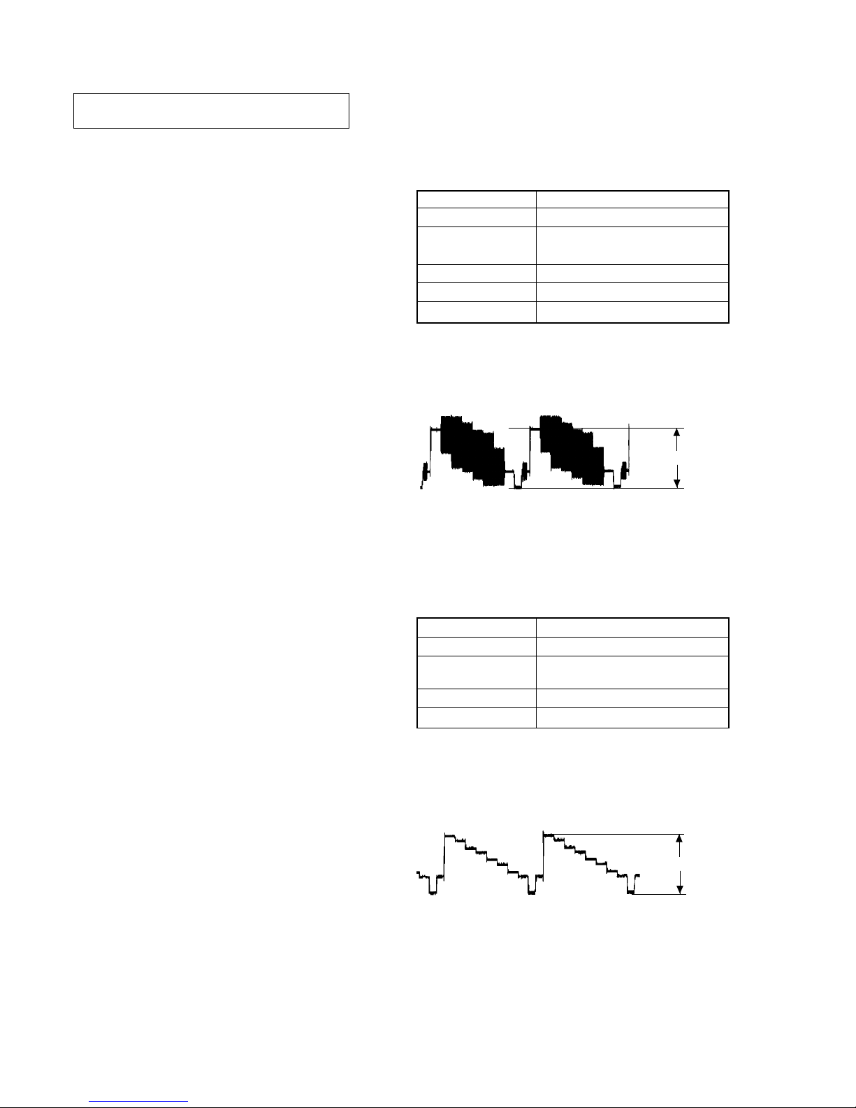
5-1. ADJUSTMENT OF VIDEO SYSTEM
1. Video Level Adjustment (DVD BOARD)
<Purpose>
This adjustment is made to satisfy the NTSC standard, and if not
adjusted correctly, the brightness will be too large or small.
Mode Video level adjustment in test mode
Signal Color bars
Test point
MONITOR OUT (VIDEO) connector
(75 Ω terminated)
Instrument Oscilloscope
Adjusting element RV501
Specification 1.0 ± 0.02 Vp-p
Adjusting method:
1) In the test mode initial menu “6” Video Level Adjustment, set
so that color bars are generated.
2) Adjust the RV501 to attain 1.0 ± 0.02 Vp-p.
Figure 5-1
2. S-terminal Output Check
<Purpose>
Check S-terminal video output. If it is incorrect, pictures will not
be displayed correctly in spite of connection to the TV with a Sterminal cable.
Mode
Video level adjustment in test mode
Signal Color bars
Test point
S VIDEO OUT (S-Y) connector
(75 Ω terminated)
Instrument Oscilloscope
Specification 1.0 ± 0.1 Vp-p
Checking method:
1) In the test mode initial menu “6” Video Level Adjustment, set
so that color bars are generated.
2) Confirm that the S-Y level is 1.0 ± 0.1 Vp-p.
Figure 5-2
1.0 ± 0.02 Vp-p
1.0 ± 0.1 Vp-p
23
HCD-S500/S800
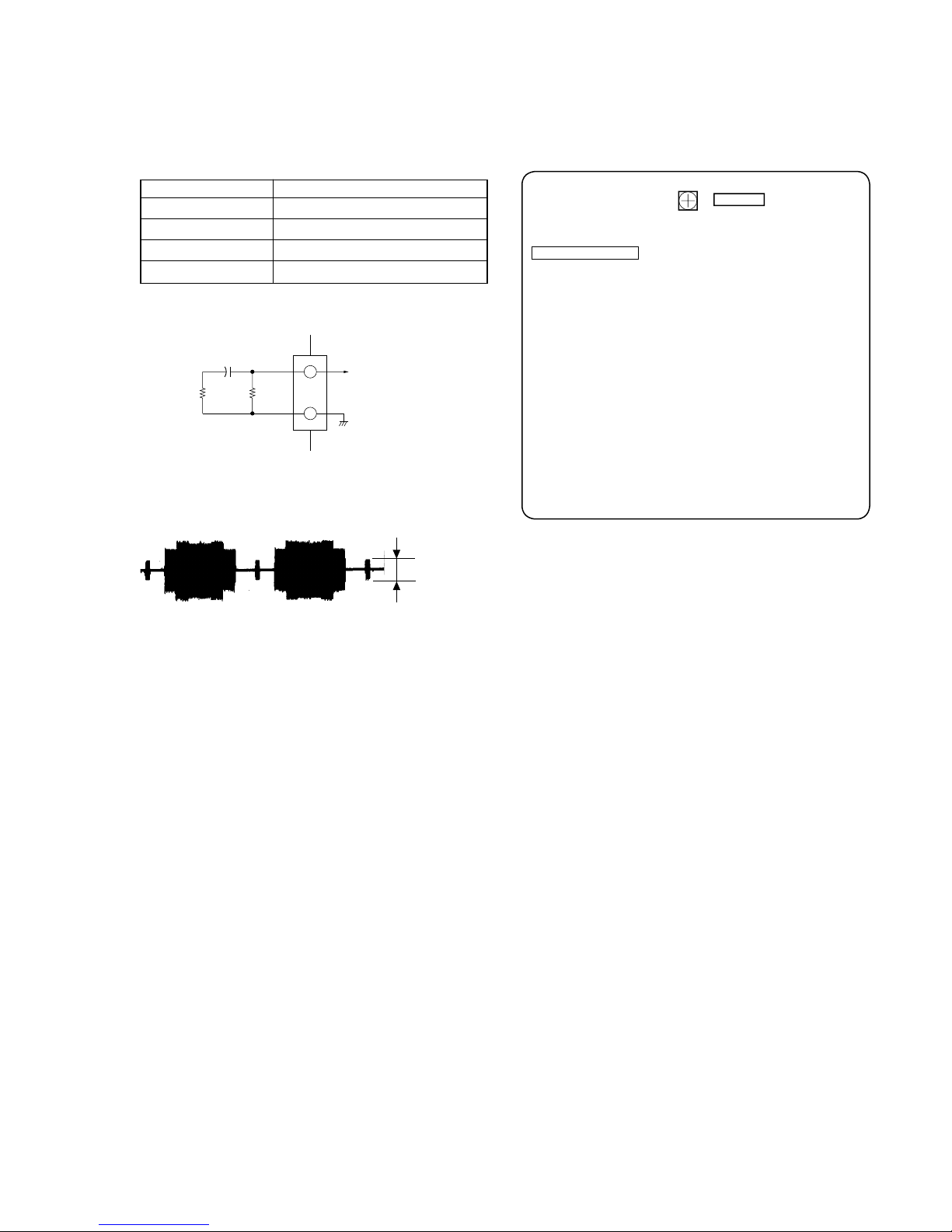
3. Checking S Video Output S-C (DVD BOARD)
<Purpose>
This checks whether the S-C satisfies the NTSC Standard. If it is
not correct, the colors will be too dark or light.
Mode Video level adjustment in test mode
Signal Color bars
Test point CN003 pin 2
Instrument Oscilloscope
Specification 286 ± 50 mVp-p
Connection:
Checking method:
1) Confirm that the S-C burst is 286 ± 50 mVp-p.
Figure 5-3
286 ± 50 mVp-p
3
2
100µF
75Ω
±1%
100k
±1%
CN003
+
Oscilloscope
5-2. ADJUSTMENT RELATED PARTS
ARRANGEMENT
DVD BOARD (SIDE A)
1
2
9
CN003
RV501
VIDEO LEVEL ADJ
24
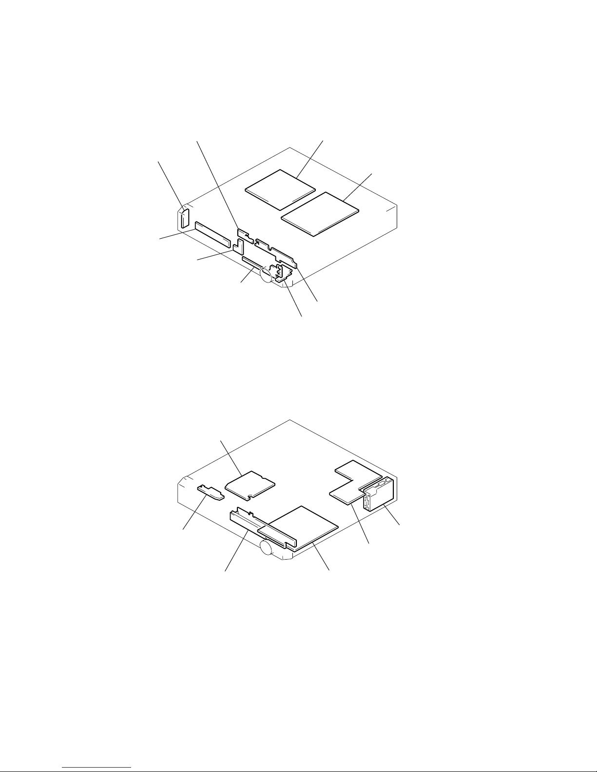
HCD-S500/S800
SECTION 6
DIAGRAMS
CIRCUIT BOARDS LOCATION
PW-1030 board
FU-1030 board
HP-1030 board
FP-1030 board
Loading board
RF-240 board
DVD board
TUNER UNI
T
I/O board
SW (B)-1030 board
SW (A)-1030 board
AMP board
DDCON-1030 board
RR-1030 board
Power board
2525
HCD-S500/S800
• Indication of transistor
CEB
These are omitte
d
Q
C
EB
These are omitte
d
THIS NOTE IS COMMON FOR PRINTED WIRING
BOARDS AND SCHEMATIC DIAGRAMS.
(In addition to this, the necessary note is printed
in each block.)
For schematic diagrams.
Note:
• All capacitors are in µF unless otherwise noted. pF: µµF
50 WV or less are not indicated except for electrolytics
and tantalums.
• All resistors are in Ω and 1/
4
W or less unless otherwise
specified.
•f: internal component.
• C : panel designation.
For printed wiring boards.
Note:
• X : parts extracted from the component side.
•a: Through hole.
• b : Pattern from the side which enables seeing.
(The other layers' patterns are not indicated.)
• A : B+ Line.
• B : B– Line.
• H : adjustment for repair.
• Voltages and waveforms are dc with respect to ground
under no-signal (detuned) conditions.
• Voltages and waveforms are dc with respect to ground in
service mode.
• Waveforms are taken with a oscilloscope.
Voltage variations may be noted due to normal production tolerances.
no mark : STOP
• Circled numbers refer to waveforms.
• Signal path.
F : FM
J : CD
c : DVD
g : VIDEO
G : Y
d : CHROMA
• Abbreviation
AR : Argentina model
AUS : Australian model
CND : Canadian model
EA : Saudi Arabia model
E12 : 220-240V AC area in E model
E32 : 110-240V AC area in E model
HK : Hong Kong model
KR : Korean model
MX : Mexican model
MY : Malaysia model
SP : Singapole model
TW : Taiwan model
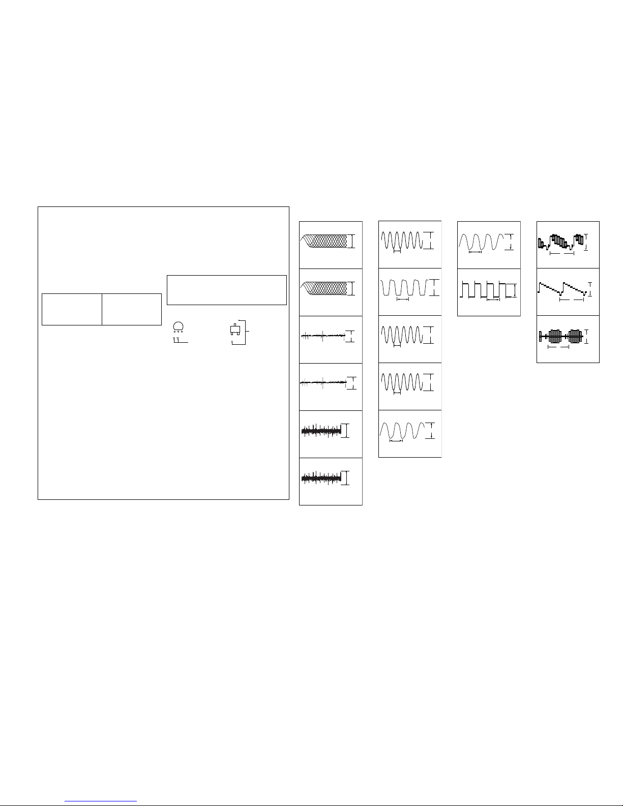
WAVEFORMS
– RF-240 BOARD –
1
2
3
4
5
6
1.5Vp-p
500mV/DIV 400ns/DIV
1.8Vp-p
500mV/DIV 40ms/DIV
1.8Vp-p
500mV/DIV 200ms/DIV
190mVp-p
100mV/DIV 40ms/DIV
840mVp-p
500mV/DIV 40ms/DIV
IC001 tl (SIGO) DVD PLAY
IC001 tl (SIGO) CD PLAY
IC001 ra (TE) DVD PLAY
IC001 ra (TE) CD PLAY
IC001 rs (FE) DVD PLAY
IC001 rs (FE) CD PLAY
1.5Vp-p
500mV/DIV 100ns/DIV
7
8
9
0
qa
IC901 ek (X2)
IC606 w; (XMCK)
IC607 qs (MCLK2)
IC102 7
(XTI)
IC103 td (X1)
3.5Vp-p
6.25ns (16MHz)
3.5Vp-p
74ns (13.5MHz)
2Vp-p
37ns (27MHz)
81.4ns (12.288MHz)
3.4 Vp-p
60.6ns (16.5MHz)
3.8Vp-p
qs
qd
IC305 qd (OUTL1+)
7.2 Vp-p
5 Vp-p
13
µ
s
20.3ns (49.152MHz)
IC300 4
qf
qg
qh
IC701 qf, qg Test Mode (Video)
IC701
9, 0
Test Mode (Video)
Q700 E Test Mode (Video)
H
2.5Vp-p
H
0.9Vp-p
H
2Vp-p
– DVD BOARD –– AMP BOARD –– I/O BOARD –
Note:
The components identified by
mark ! or dotted line with mark
! are critical for safety.
Replace only with part number
specified.
Note:
Les composants identifiés par
une marque ! sont critiques
pour la sécurité.
Ne les remplacer que par une
pièce portant le numéro spécifié.
Caution:
Pattern face side: Parts on the patter n face side seen from
(Conductor B) the patter n face are indicated.
Parts face side: Parts on the par ts face side seen from
(Component A) the parts face are indicated.
2626
HCD-S500/S800
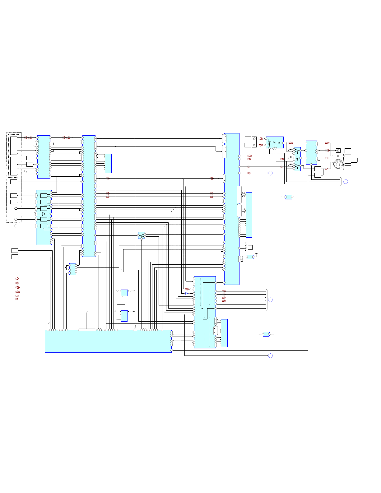
6-1. BLOCK DIAGRAMS
– RF/SERVO, VIDEO SECTION –
: FM
: CD
: DVD
: CHROMA
: Y
• Signal Path
• R-CH is omitted due to same as L-CH.
: VIDEO
DVD/CD
PDIC
OPTICAL PICK-UP
DVD/CD
LD MOD
DVD LD
DRIVE
Q001
CD LD
DRIVE
Q002
RF
A-D
E-H
VC
DVD LD
CD LD
PD
VR
SW
IC001
DVD/CD RF AMP
DIGITAL SERVO
RF IN
2
14
11
7
10
15
18
VC
19
DVD LD
25
CD LD
26
DVD PD
21
LD SEL
24
CD PD
22
A-D
E-H
A2-D2
59
SIGO
41
TE
40
TZIN
44
MON
33
MIRR
37
TZC
38
DFT
47
SCLK
48
SDEN
46
SWD
45
SRD
27
LDON
39
VCI
36
PI
35
PIIN
42
FE
IC401
FOCUS/TRACKING
COIL DRIVE
SPINDLE/SLED/LOADING
MOTOR DRIVE
FOCUS
COIL
DRIVE
FOCUS
COIL
FCS +/-
48
1
40
SVC
FDRV+
FDRV-
TRACKING
COIL
DRIVE
TRACKING
COIL
TRK +/-
3
4
TDRV+
TDRV-
SPINDLE
MOTOR
DRIVE
SPM +/-
13
MDSO
M
SPINDLE
MOTOR
47
46
45
SPFG
SLED
MOTOR
DRIVE
SLA +/SLB +/-
7
SLDA
M
SLED
MOTOR
10
SLDB
LOADING
MOTOR
DRIVE
LDM +/-
16
LMP
M
LOADING
MOTOR
17
LMM
36
37
.
34
35
.
28
27
.
24
25
.
32
29
5
SLE
CHUCK
SENSOR
19
MUTE12
20
MUTE34
39
POWER SAVE
TRAY
SENSOR
IC302
SERVO DSP
RFIN1
131
RFIN2
128
ADC0
135
ADC1
136
ADC2
137
ADC7
144
PGIN
172
MIRR
197
TZC
196
DFCTI
185
SCK
175
GIO13
180
SDO
174
ADC6
143
SDI
173
PDM2
204
PDM3
205
MDSO
159
MDPO
161
ADC4
140
PWM0
198
PWM1
199
ADC3
139
GIO9
176
GIO10
177
GIO2
168
GIO0
167
ADC5
142
LIMIT
SENSOR
INT2
166
PDM0
202
PDM1
203
15
LMCTL
PWM2
200
73
76
78
81
.
96
103
SD0-7
AD0-7
2
9
D0-7
11
15
17
19
.
A0-7
8
8
8
8
WSAD0-7
SDI0-7
HD8-15
HA0-7
95
PLCKO
66
DOUT
62
DATA
63
BCLK
65
LRCK
68SDCK
69XSHD
71XSAK
72
SDEF
25
XWAT
207
XWR
208
XRD
195
TDO
194
TCK
192
TMS
191
TRST
156
XDSPRST
5
6
1
2
IC304
70
XSRQ
157
XARPRST
22
HINT
21
XINT
44
51
53
60
.
27
36
38
XMWR
41
XRAS
42
XOE
39
XCAS
MA0-9
MD0-15 MEMD0-15
MEMA0-9
IC303
16M
DRAM
IC503
AV DECODER
215
218
213
.
210
208
.
205
200
203
198
.
195
193
.
192
.
HD0-15
HAD0-21
31
34
36
39
.
16
22
8
DTI0-7
CDIN2
22
CDIN1
23
CDBCK
25
CDLRK
26
ICLK
41
ISTART
44
IVAL
45
IERR
43
HWAITOB
224
HRWB
221
HSCB
220
TCK
120
TMS
121
TRST
122
IREQ
46
VRIF
84
80
COMP OUT
74
Y OUT
77C OUT
227
DMREQ1
223
HIREQO
229
DMREQ0
190
HAD23
191
HAD22
228
DMACK0
12
ACLK
226
DMACK1
29
CRPCLK
182
180
CLK
TDI
118
131
134
128
.
125
124
.
127
133
130
136
.
139
137
.
140
.
SDDQ0-15
174
.
177
171
.
168
.
165
.
163
.
160
.
158
.
159
.
157
162
.
164
.
167
.
170
.
173
.
176
.
.
.
.
SDDQ0-15
SDAQ0-11
.
.
144
SDCS0B
143
SDCS1B
155
SDDQM0
154
SDDQM1
149
SDCLK
146
SDCKE
152
SDWEOB
151
SDCKSOB
147
SDRASOB
IC504,505
16M
SDRAM
AVDD6
181
A3.3V
VIDEO
LEVEL
RV501
2
AVDD7
184
AVDD8
187
1.8V
REG
IC501
1
D3.3V
IC801
PLAYBACK SIGNAL
PROCESSOR
29
WCK
123
8
111
114
117
120
.
169
176
WAD0-7
SD0-7
8
24
IC802
SDCK
166
XSHD
165
XSAK
167
TDI
27
SDEF
168
TCK
26
TMS
30
TRST
31
XSRQ
164
DCLK
141
64
DSAL
69
DSAC
71
DSALFE
74DSALS
60
BCKAO
13
9XRST
2
XMSLAT
7
MSREADY
10
SMUTE
6
MSDATO
4
MSDATI
3
MSCK
11 MCK
TDO
TDO
EXCKO
B
AUDIO
SECTION
D
MAIN
SECTION
139
136
134
131
.
DQ0-7
A0-11
IC803
16M
SDRAM
DCKE
142
XWE
143
XCAS
144
XRAS
145
SDATAL
SDATAC
SDATALF
SDATALS
DSBC
DSMCK
VIDEO IN
VIDEO1
VIDEO
J700
43
2
1
C
Y
A
AUDIO-1
SECTION
1
VIDEO IN
VIDEO2
J600 (1/4)
3
2 5 4
7
5
11
IC700
INPUT SEL
14
12
6
8
9
7
3
16
1
2
IC702
OUTPUT SEL
INA
2
INB
4
INC
7
15
OUTA1
14
OUTA2
13OUTB1
12OUTB2
10
OUTC1
9
OUTC2
MUTE
IC701
VIDEO AMP
1
BUFFER
OFFSET
SWITCH
Q700,702,703
Q701,704
VIDEO OUT
VIDEO1
S VIDEO
MONITOR
OUT
J600 (2/4)
VMUTE
VSEL2
VSEL1
20
DO
3
2.5V
REG
IC804
1
D3.3V
D2.5V
3
5V
REG
IC601
1
10V
VIDEO 5V
SPDIF
HCS
24
XCS
23
56
CKSW157OCSW178OCSW2
48
XDRVMUTE
84
XLDON
63
CS5X62CS4X
81
48/44.1K
IC102
CLOCK
GEN
14
15
7
8
10
13
3
X102
27MHz
MCKI
187
SCKI
189
CLKIN
182
IC107
IC108
16M
FLASH
OPT
16
HD0-15
21
HA1-21
21
HA1-21
235
232
237
.
240
5
2
7
.
10
RSTB
231
SCLK
159
162
157
.
154
151
152
149
.
148
.
.
EXCKO
49
DREQ1
40
TRM + XKRRST
16
INT0
61
CS3X60CS2X
50
DACK147DACK0
22
TSDM
5
MUTE5
21
SP MUTE
TSD
16
HD0-15
46
DREQ0
IC103 (1/2)
SYSTEM CONTROL
17
INT118INT2
36
XARPRST
35
XRST
67
XWAIT
70
XRD
71
XWRH
58
CS0X
76
XFRST
512FS AVD
33M AVD
27M AVD
TRM/XKRCS
8
21
22
28
29
30
INT5
INT6
SI1
SO1
SC1
82
WIDE
C
CPU
SECTION
TRST
85 100
HD0-15
16
102 109
.
120
15
111 118
..
HA0-21
22
(KHM-240 AAA/J1RP)
2727
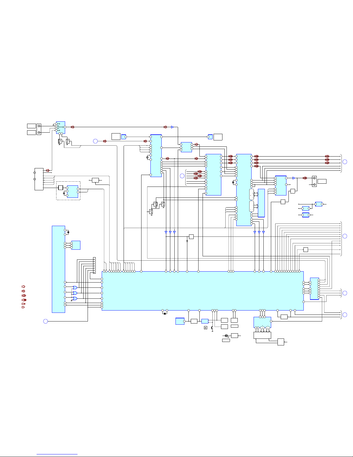
HCD-S500/S800
– CPU SECTION –
: FM
: CD
: DVD
: CHROMA
: Y
• Signal Path
• R-CH is omitted due to same as L-CH.
: VIDEO
IC103 (2/2)
SYSTEM CONTROL
54X0
25
SI0
26
SO0
1
2
3
IC106
27SC0
4
5
6
IC106
51
XIFCS
12
13
11
IC106
20
INT4
83
MA MUTE
AUDIO IN L
VIDEO1
TUNER BLOCK UNIT
AUDIO IN L
VIDEO2
FM
DET
9.5V
5
1
2
4
10
9
3
IC600
INPUT SEL
BA
IC603
Q603
J600 (3/4)
FM
AM
R-CH
L-CH
R-CH
DI
DO
CK
CE
TUNED
FM DET
Q607
MUX
4
X0
14
X1
13
2
RDATA
16
RCLK
IC604
RDS
X601
4.332MHz
S500: AEP,UK / S800 MODEL
TUN DO
TUN DI
TUN CLK
TUN CE
TUN STE
31
LIN
1
15
DOUT
14
BCK
13
LRCK
IC602
AUDIO
A/D CONV
FM +B
SWITCH
Q600-602
FM7.5V
4
5
6
3
2
1
8
CN101
SI0
SO0
SC0
XIFCS
XIFINT
XFRRST
FR
FR
70
SDI
4
IFSC0
3
CLK
5
XVIFCS
68
XFRINT
67
IFOK
69
XFRRST
66
RDATA
RCLK
ASEL2
Q604
ASEL1
FM ON
100
I2HLP
93
RDSCLK
98
TUN DO
96
TUN DI
99
TUN CLK
89
TUN CE
95
TUN END
94
FM
RDATA
RCLK
TUN DO
TUN DI
TUN CLK
TUN CE
TUN STE
FM ON
7
DIG DI
24
DIR DO
8
DIG CLK
19
DIR CE
13
DSP CS32DAC CS
DIG DI
DO
DIG CLK
CS DIR
HCS
LT
53X1
7
WP
X101
39
SCL
38
SDA
7
6
5
EEPROM
IC101
33
AD RST
RSTB
6
SYSCLK
16
DIGITAL IN
OPTICAL
VIDEO 2
B
RF/SERVO
VIDEO
SECTION
3
OUT
IC602
DO
DIGDI
DIGCLK
CSDIR
DIN1
4 2
SPDIF
IC606
DIN0
3
DO
35
DI
36
CL
38
CE
37
XIN
22
XOUT
21
ERROR
34
AUDIO
24
1
2
X600
12.288MHz
Q908 Q909
Q910
DIGITAL OUT
OPTICAL
(CD ONLY)
1
IN
IC603
16DATA
13
CKOUT
14
BCK
15
LRCK
20
XMCK
EXID2
57 47F2FLREX1
IC612
DIGITAL AUDIO
DIGITAL AUDIO
PROCESSOR
I/F RECEIVER
EXID1
58
EXI MCK
59
EXI BCK
55
EXI LRCK
56
DSIFL
63
46
F2CSWEX2
45
F2SLR
43
F2BCK
44
F2LRCK
49
CKOUT
IC900
65
66
67
62
52
XMODE
48
SDATAL
SDATAC
SDATALF
SDATALS
DSBC
DSMCK
DSICT
DSISW
DSISL
DSBCKF
MCK
SYNC
78
INIT
79
SELEXT
77
17
XSTATE
5
6
IC900
3
4
IC900
SDI1
18 23SDO1
IC607
AUDIO DSP
SDI2
30
SDI3
114
BCKI1
17
BCKI2
29
LRCKI1
15
KFSIO
22
LRCKI2
28
MCLK1
9
MCLK2
12
X601
13.5MHz
GP8
59
EXLOCK
69
BST
56
DIGDI
DIGCLK
HCS
HD IN
33
HCLK
34
HCS
36
PM
113
XRST
2
24
SDO2
25
SDO3
20
BCK
DATA
2 7
LOUT
IC608
AUDIO
D/A CONV
26
SDO4
19
LRCK
67
GP10
14
SCK
57
IC610
112
110
.
109
97
.
92
82
85
.
83
66
.
64
.
A0-15
45WE0
44CS0
IC604
SRAM
108
107
.
105
102
99
98
80
.
77
75
.
72
.
D0-15
.
68
GP9
32
HACN
35
HDOUT
11
10
IC900
13
12
IC900
9
8
IC900
DIGDI
DIGCLK
LT
DATA
13
CLK
14
LT
15
MCLK
16
BCK
1
LRCK
3 8
ROUT
R-CH
MUTE
CONT
MUTE
Q606
Q900
17
DSP PLOCK
20
DIR XST
18
DIR ERR
48
SYNC
23
DIR XMODE
12
DSP PM
15
DSP BST11DSP RST
6
DSP DO
14
DSP HACN
16
DSP GP9
44
AU MUTE
22
DIR AD
MUTE
Q903
1
DAMP DATA
MUTE
Q902
2
DAMP CLK
28
CS129CS230CS3
25
DAMP MUTG
31
DAMP RST
49
OCP
46
RELAY
55
FL MUTE
50
HPSW
61
SERI DATA
STOP
90
26
DAMP MUTEN
IC902
SERIAL→ PARALLEL
62
SERI CLK
63
IO DATA
64
IO LAT
65
IO RST
DI1
26
CLK
3
DO1
15
LATCH
4
RSTB
2
24
P0
23
P1
6
P14
7
P13
22
P2
8
P12
21
P3
11
DVD PW
12
DIMM
45
V MUTE
ASEL1
ASEL2
F
AUDIO-2
SECTION
D
VIDEO
SECTION
AUDIO OUT
VIDEO1
POWER
VOLUME
J600 (4/4)
R-CH
E
AUDIO-2
SECTION
D1
D2
D3
SCK
BCKO
LRCKO
SCDT
SHIFT
LAT1
LAT2
LAT3
INIT
NS MUTE
PG MUTE
EN
DIAG
RELAY
HP MUTE
HP SW
VSEL1
VSEL2
VMUTE
STPOW
43
FL CS
56
IC802
FL DRIVER
RESET
PCONT2
PCONT1
RESET
G
POWER
SECTION
RESET
34
ENA
83
FL CLK
53
FL DATA
54
40 51539
G1 12S1 35
AD14AD2
3
63
DAT
62
CLK
61
CS
60
RST
Q901
FL801
FLUORESCENT
INDICATOR TUBE
DC/DC
CONV
Q803,804
T801
6.5V
VOL
ENCODER
LED
DRIVE
6.5V
Q801
D812
ENB
84
S800
FUNCTION
KEY
S801-805
IC901
CPU
FUNCTION
KEY
S821-825
KEY080KEY181KEY2
82
RESET
IC903,904
SIRCS
SWITCH
Q906,907
RDS DATA
92
SIRCS
91
X2
38
REMOTE
CONTROL
RECEIVER
1
IC101
S806
X1
39
X901
16MHz
10V
REG
12V
IC601
3 1
5V
REG
IC600
3 1
2.5V
REG
IC605
3 1
10V
5V
2.5V DA3V
C
RF/SERVO
SECTION
A
RF/SERVO
SECTION
TRST
SPDIF
g
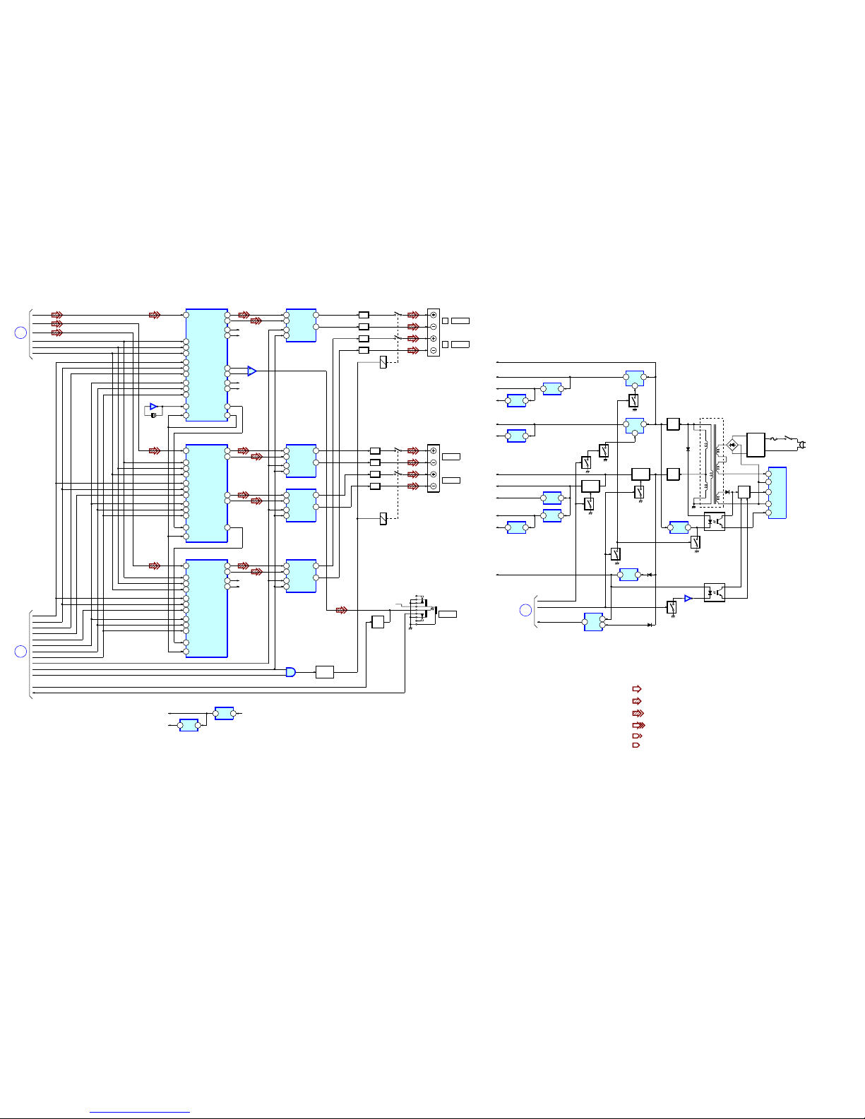
2828
HCD-S500/S800
– POWER SECTION –
: FM
: CD
: DVD
: CHROMA
: Y
• Signal Path
• R-CH is omitted due to same as L-CH.
: VIDEO
E
AUDIO-1
SECTION
DATA
43
21
OUTL1-
IC305
STREAM PROCESSOR
STREAM PROCESSOR
STREAM PROCESSOR
XFS1
64
BCK
44
LRCK
45
INA
8
2
OUTA
IC301
POWER DRIVER (F)
INB
11
EN
7
DIAG
12
SCDT
38
SCSHIFT
37
SCLATCH
36
INIT
41
NSPMUTE
39
PGMUTE
40
XFS0IN
28
24
FSOI
74
IC300
X300
49.152MHz
18
OUTL2-
7
OUTR1-
R-CH
4
OUTR2-
R-CH
24
OUTL1+
15
OUTL2+
10
OUTR1+
R-CH
1
OUTR2+
R-CH
77XFSOOUT
73
FSOCKO
17
OUTB
D2
D1
D3
SCK
BCKO
LRCKO
DATA
43
IC308
XFS1
64
BCK
44
LRCK
45
INA
8
2OUTA
IC306
POWER DRIVER (C)
INB
11
EN
7
DIAG
12
SCDT
38
SCSHIFT
37
SCLATCH
36
INIT
41
NSPMUTE
39
PGMUTE
40
XFS0IN
28
FSOI
74
24OUTL1+
15OUTL2+
77
XFSOOUT
17OUTB
DATA
43
IC310
XFS1
64
BCK
44
LRCK
45
INA
8
2
OUTA
IC309
POWER DRIVER (R)
INB
11
EN
7
DIAG
12
SCDT
38
SCSHIFT
37
SCLATCH
36
INIT
41
NSPMUTE
39
PGMUTE
40
XFS0IN
28
FSOI
74
24
OUTL1+
15
OUTL2+
17
OUTB
10
OUTR1+
R-CH
1
OUTR2+
R-CH
F
CPU
SECTION
SCDT
SHIFT
LAT1
LAT2
LAT3
INIT
NS MUTE
PG MUTE
EN
DIAG
RELAY
HP MUTE
HP SW
RELAY
DRIVE
Q301
1
2
4
IC312
INA
8
2
OUTA
IC307
POWER DRIVER (W)
INB
11
EN
7
DIAG
12
17OUTB
10
OUTR1+
1OUTR2+
5
6
7
IC401
J900
R-CH
L
L
FRONT
RY301
REAR
CENTER
RY302
WOOFER
PHONES
Q900
MUTE
T901
AC
IN
POWER TRANS
+5V
REG
1
3
IC003
LF901,902
LINE
FILTER
D902
F901
S901
POWER
REG
Q901-903
D
3
S
2
VCC
4
GND
5
FB/OCP
1
IC901
SWITCHING REG
PC901
RECT
D911
D910
D906
RECT
D909
ERROR
AMP
2
1
IC902
Q905
POWER
SWITCH
Q907
+5.6V
REG
1
3
IC905
+3,3V
REG
1
2
IC906
5
Q910
+6.5V
REG
1
2
IC903
5
Q906
Q911
+12V
SWITCH
Q002
Q001
Q908
Q909
D917
PC902
IC907
Q915
RESET
5
1
2
IC904
D913
G
CPU
SECTION
P.CONT2
RESET
P.CONT1
+5V
REG
1
3
IC002
+3.3V
REG
1
3
IC001
+1.8V
REG
1
3
IC006
+5V
REG
1
3
IC004
+3.3V
REG
1
3
IC005
+27V
DA +5V
DA +3,3V
DVD +3.3V
+1.8V
+12V
M +12V
D +5V
A +5V
A +3,3V
E +5.6V
+6.5V
+5V
REG
1
3
+3.3V
REG
1
3
IC303
+5V
+3,3V
+6.5V
IC302
L401,C451
LPF
L401,C452
LPF
L402,C453
LPF
L402,C454
LPF
L403,C455
LPF
L403,C456
LPF
L404,C457
LPF
L404,C458
LPF
J401 (1/2)
J401 (2/2)
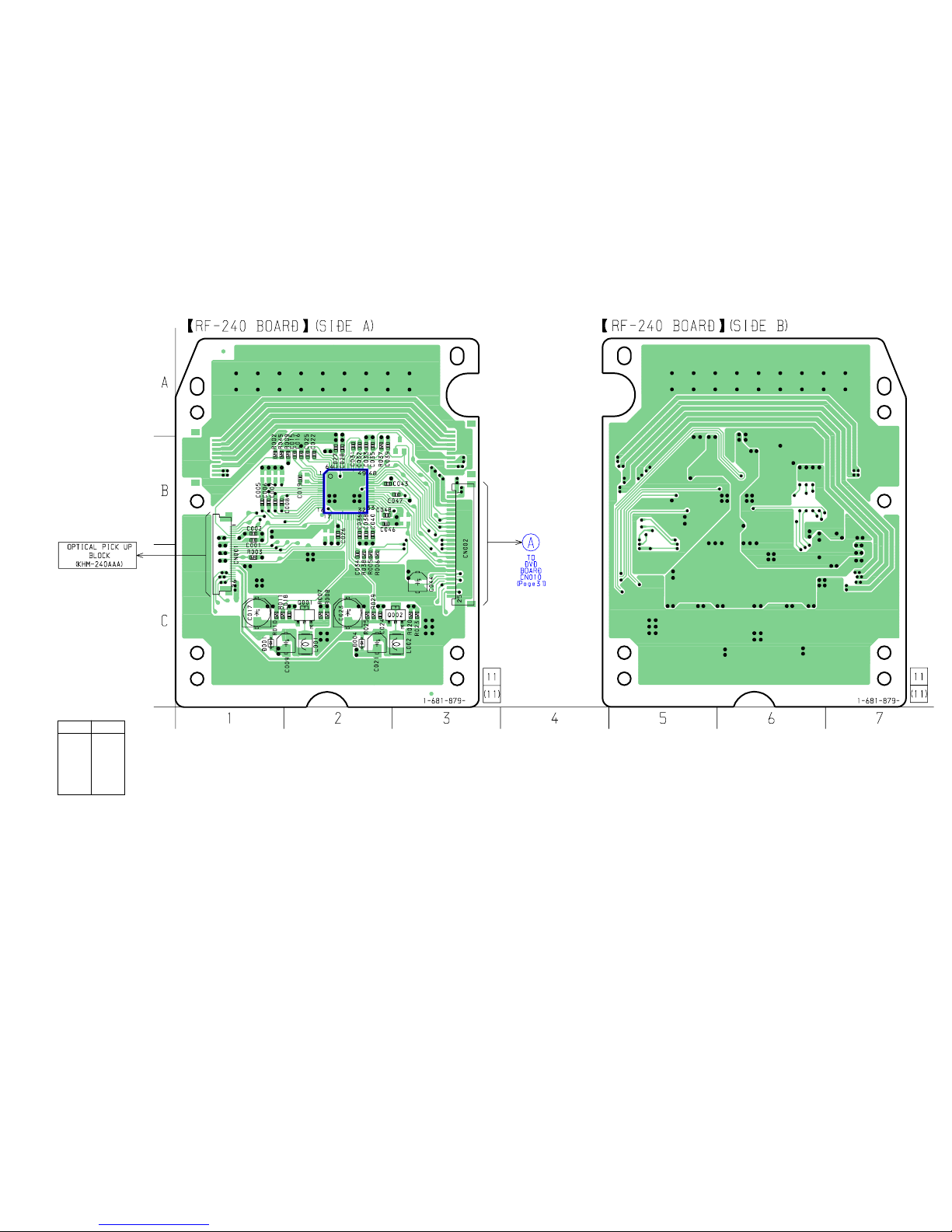
2929
HCD-S500/S800
6-2. PRINTED WIRING BOARD – RF SECTION –
IC001
Ref. No. Location
D001 C-1
D004 C-2
IC001 C-2
Q001 C-2
Q002 C-3
• Semiconductor
Location
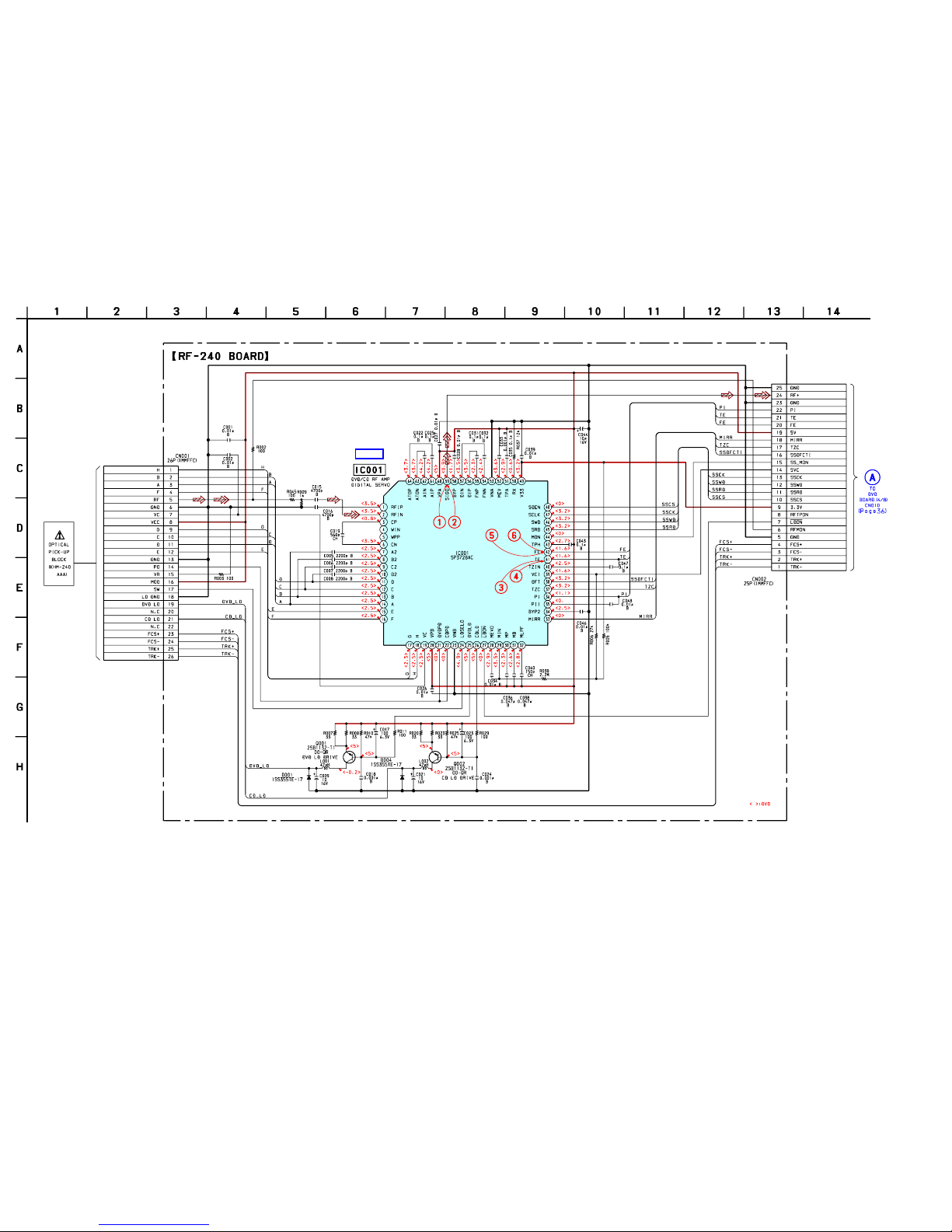
3030
HCD-S500/S800
6-3. SCHEMATIC DIAGRAM – RF SECTION –
IC B/D
• See page 25 for Wavefoms. • See page 58 for IC Block Diagrams.
 Loading...