

Sony DVX-11-A Service manual
DVX-11A
System
Laser Semiconductor laser
Signal format system
US, Canadian models: NTSC
AEP, UK models: PAL
E model: PAL/NTSC Switchable
Audio characteristics*
Frequency response DVD:
5 Hz to 22 kHz
CD:
5 Hz to 20 kHz
Signal-to-noise ratio 102 dB (AUDIO OUT L/R
jacks only)
Harmonic distortion 0.003 %
Wow and flutter Less than detected value
(±0.001 % W PEAK)
* Measured from the AUDIO OUT jacks.
When you play PCM sound tracks with a 96 kHz
sampling frequency, the output signals from the
DIGITAL OUT jack are converted to 96 kHz
sampling frequency.
General
Outputs AUDIO OUT L/R:
Phono jack/2 Vrms /
10 kilohms
VIDEO OUT:
Phono jack/1.0 Vp-p/
75 ohms
DIGITAL OUT:
Optical output jack/
–18 dBm (wave length:
660 nm)
Power requirements 12 V DC car battery
(negative ground)
Dimensions
Approx. 178 × 50 × 170 mm
(w/h/d)
Mounting dimensions
Approx. 182 × 53 × 155 mm
(w/h/d)
Mass Approx. 1.2 kg
Operating temperature –10 °C to 55 °C
Operating humidity 25 % to 80 %
Supplied accessories Card remote commander
RM-X129
Parts for installation and
connections (1 set)
Note
This unit cannot be connected to a digital preamplifier
or an equalizer which is Sony BUS system compatible.
Design and specifications are subject to change
without notice.
SERVICE MANUAL
Ver 1.2 2004.10
Copyrights
This product incorporates copyright protection
technology that is protected by method claims of
certain U.S. patents, other intellectual property
rights owned by Macrovision Corporation, and
other rights owners. Use of this copyright
protection technology must be authorized by
Macrovision Corporation, and is intended for
home and other limited viewing uses only unless
otherwise authorized by Macrovision
Corporation. Reverse engineering or disassembly
is prohibited.
Manufactured under license from Dolby
Laboratories.
“Dolby” and the double-D symbol are
trademarks of Dolby Laboratories.
Confidential unpublished works. Copyright
1992–1997 Dolby Laboratories. All rights
reserved.
“DTS,” “DTS Digital Surround” and “DTS
Digital Out” are trademarks of Digital Theater
Systems, Inc.
US Model
Canadian Model
AEP Model
UK Model
E Model
Model Name Using Similar Mechanism NEW
Base Mechanism Type SA-MDAM01
SPECIFICATIONS
9-877-352-03 Sony Corporation
2004J05-1 e Vehicle Company
© 2004.10 Published by Sony Engineering Corporation
MOBILE DVD PLAYER

DVX-11A
NOTES ON HANDLING THE OPTICAL PICK-UP
BLOCK OR BASE UNIT
The laser diode in the optical pick-up block may suffer electrostatic break-down because of the potential difference generated
by the charged electrostatic load, etc. on clothing and the human
body.
During repair, pay attention to electrostatic break-down and also
use the procedure in the printed matter which is included in the
repair parts.
The flexible board is easily damaged and should be handled with
care.
NOTES ON LASER DIODE EMISSION CHECK
The laser beam on this model is concentrated so as to be focused
on the disc reflective surface by the objective lens in the optical
pick-up block. Therefore, when checking the laser diode emission, observe from more than 30 cm away from the objectiv e lens.
NOTES ON HANDLING THE OPTICAL PICK-UP BLOCK .
The laser diode in the optical pick-up block may suffer electrostatic break-down easily. When handling it, perform soldering
bridge to the laser-tap on the flexible board. Also perform measures against electrostatic break-down sufficiently before the operation. The flexible board is easily damaged and should be handled
with care.
CAUTION
Use of controls or adjustments or performance of procedures
other than those specified herein may result in hazardous radiation exposure.
US, Canadian models:
Laser Diode Properties
• Material: GaAlAs
•Wav elength: 780 nm
• Emission Duration: continuous
• Laser Output Power: less than 44.6 µW*
*This output is the value measured at a distance of 200 mm
from the objective lens surface on the Optical Pick-up Block.
AEP, UK models:
This label is located on the bottom of the
chassis.
laser-tap
OPTICAL PICK-UP FLEXIBLE BOARD
Notes on chip component replacement
•Never reuse a disconnected chip component.
• Notice that the minus side of a tantalum capacitor may be damaged by heat.
Flexible Circuit Board Repairing
•Keep the temperature of the soldering iron around 270 ˚C during repairing.
• Do not touch the soldering iron on the same conductor of the
circuit board (within 3 times).
• Be careful not to apply force on the conductor when soldering
or unsoldering.
CAUTION INVISIBLE
VIEW DIRECTLY WITH OPTICAL INSTRUMENTS
This label is located on the drive unit’s internal
chassis.
LASER RADIATION WHEN OPEN
DO NOT STARE INTO BEAM OR
SAFETY-RELATED COMPONENT WARNING!!
COMPONENTS IDENTIFIED BY MARK 0 OR DOTTED
LINE WITH MARK 0 ON THE SCHEMATIC DIAGRAMS
AND IN THE PARTS LIST ARE CRITICAL TO SAFE
OPERATION. REPLACE THESE COMPONENTS WITH
SONY PARTS WHOSE PART NUMBERS APPEAR AS
SHOWN IN THIS MANUAL OR IN SUPPLEMENTS PUBLISHED BY SONY.
2
ATTENTION AU COMPOSANT AYANT RAPPORT
À LA SÉCURITÉ!
LES COMPOSANTS IDENTIFIÉS P AR UNE MARQUE 0
SUR LES DIAGRAMMES SCHÉMATIQUES ET LA LISTE
DES PIÈCES SONT CRITIQUES POUR LA SÉCURITÉ
DE FONCTIONNEMENT. NE REMPLACER CES COMPOSANTS QUE PAR DES PIÈCES SONY DONT LES
NUMÉROS SONT DONNÉS DANS CE MANUEL OU
DANS LES SUPPLÉMENTS PUBLIÉS PAR SONY.

TABLE OF CONTENTS
1. SERVICING NOTES ................................................ 4
2. GENERAL
Location of Controls ....................................................... 7
3. DISASSEMBLY
3-1. Disassembly Flow ........................................................... 11
3-2. Cover ............................................................................... 12
3-3. Front Panel Assy ............................................................. 12
3-4. Mechanism Deck (SA-MDAM01) ................................. 13
3-5. DSP Board, MAIN Board ............................................... 13
3-6. Bracket L/R ..................................................................... 14
3-7. Chassis (DVD) Block...................................................... 14
3-8. SERVO Board ................................................................. 15
3-9. Gear Cover ...................................................................... 15
3-10. Feed Motor (Loading) (M1) ........................................... 16
3-11. Chassis Clamp ................................................................. 16
3-12. Bracket Roller ................................................................. 17
4. ELECTRICAL ADJUSTMENTS......................... 17
DVX-11A
5. DIAGRAMS
5-1. Block Diagram ................................................................ 18
5-2. Note for Printed Wiring Boards and
Schematic Diagrams ....................................................... 19
5-3. Printed Wiring Boards – MAIN Section (1/2) – ........... 20
5-4. Printed Wiring Boards – MAIN Section (2/2) – ........... 21
5-5. Schematic Diagram – MAIN Section (1/2) –................ 22
5-6. Schematic Diagram – MAIN Section (2/2) –................ 23
5-7. Printed Wiring Board – KEY Board –........................... 24
5-8. Schematic Diagram – KEY Board – ............................. 25
5-9. IC Pin Function Description ........................................... 27
6. EXPLODED VIEWS
6-1. Overall Section................................................................ 29
6-2. Front Panel Section ......................................................... 30
6-3. Chassis Section ............................................................... 31
6-4. Mechanism Deck Section-1 (SA-MDAM01)................. 32
6-5. Mechanism Deck Section-2 (SA-MDAM01)................. 33
7. ELECTRICAL PARTS LIST ............................... 34
3
DVX-11A
Ver 1.2
SECTION 1
SER VICING NOTES
TEST DISC
This set can playback a CD-R, CD-RW for audio use and DVD.
When test this set, use the following test disc.
Test disc for CD-R: TCD-R082LMT (Part No.: J-2502-063-1)
Test disc for CD-RW: TCD-W082L (Part No.: J-2502-063-2)
Test disc for DVD:
NTSC:
HLX-504 (Part No.: J-6090-088-A) (single layer)
HLX-505 (Part No.: J-6090-089-A) (dual layer)
PAL:
HLX-506 (Part No.: J-6090-077-A) (single layer)
HLX-507 (Part No.: J-6090-078-A) (dual layer)
Note for Replacing The DSP Board
This set requires software writing to the IC401 on the DSP board,
if the DSP board was replaced. Therefore, be sure perform the
software writing as below.
1. Download the software from website of ESI and write this
software to a CD-R.
2. Insert the CD-R to the set and load the software.
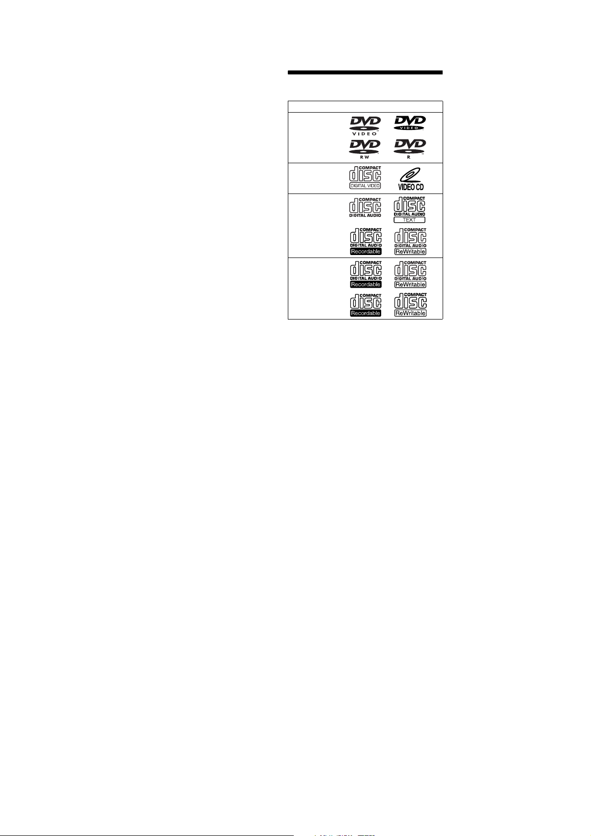
Playable discs
Format of discs
DVD
Video CD
Audio CD/
CD-R/CD-RW
CD-R/CD-RW
(MP3/JPEG)
“DVD VIDEO,” “DVD-R” and “DVD-RW” are
trademarks.
DVD
A DVD contains both audio and visual data. A 12
cm disc can hold 7 times the amount of data
contained in a CD-ROM, which equals to 4
consecutive hours of playing time (8 hours for
double-sided discs). DVDs are divided into 4
types: single sided single layer, single sided
double layer, double sided single layer, and
double sided double layer.
Video CD (VCD)
A Video CD can contain both audio and visual
data on a disc the same size as a regular Audio
CD. The playing time is 74 minutes for a
standard 12 cm CD.
Audio CD
An Audio CD containing audio data. The playing
time is 74 minutes for a standard 12 cm CD.
CD-Recordable (CD-R)
With a CD-R, you can edit audio data. You can
write information on a CD-R only once.
CD-Rewritable (CD-RW)
With a CD-RW, you can edit audio data. You can
write information on a CD-RW again and again.
4

DVX-11A
CD-Extra
A CD-Extra has two sections (sessions) for audio
and data respectively. You can only play the
section of audio on this unit.
Notes
This unit conforms to the PAL colour system. A disc
•
recorded in a colour system other than P AL, such as
NTSC or SECAM, cannot be played.
•
You can play DVD-Rs/DVD-RWs and CD-Rs/CDRWs designed for audio with this
depending on the recorded conditions, you cannot
play some discs.
•
The discs listed below cannot be played on this unit:
–8 cm discs
– CD-ROM (the data other than the MP3 or JPEG
files)
– CD-G
–Photo-CD
– VSD (Video single disc)
–DVD-ROM
–DVD-RAM
–DVD-Audio
–Active-Audio (Data)
– CD-Extra (Data)
–Mixed CD
– SVCD (Super Video CD)
–DVD-RW recorded in VR mode
unit. However,
Note on transparent discs
12 cm discs containing of only an inner 8 cm
data portion (the rest is transparent) cannot be
played on this unit.
Music discs encoded with copyright
protection
This unit is designed to play back discs that
conform to the Compact Disc (CD) standard.
Recently, various music discs encoded with
copyright protection are marketed by some
record companies. Please be aware that among
those discs, there are some that do not conform to
the CD standard and may not be playable and
recordable by this product.
Region code
This system is used to protect software
copyrights.
The region code is located on the bottom of the
unit, and only DVDs labelled th
e identical region
code can be played on this unit.
MODEL NO.
DVD PLAYER
DC : 12V
N E G A T I V E G R O U N D
Region code
DVDs labe lled can be also played on this
ALL
AUDIO OUT
DIGITAL OUT
REMOTE SIGNAL IN
TOP
FRONT
REAR
BOTTOM
R
L
VIDEO OUT
unit.
If you try to play any other DVD, the message
“Cannot play this disc.” will appear on the
monitor screen. Depending on the DVD, no
region code may be labelled even though playing
the DVD is prohibited by area restrictions.
Note on playback operations of DVDs
and VCDs
Some playback operations of DVDs and VCDs
may be intentionally set by software producers.
Since this unit plays DVDs and VCDs according
to the disc contents the software producers
designed, some playback features may not be
available. Also, refer to the instructions supplied
with the DVDs or VCDs.
Notes on MP3 files
MP3 (MPEG 1 Audio Layer-3) is a standard
technology and format for compressing a sound
sequence. The file is compressed to about 1/10 of
its original size. Sounds outside the range of
human hearing are compressed while the sounds
we can hear are not compressed.
Notes on discs
Yo u can play MP3 files recorded on CD-ROMs,
CD-Rs, and CD-RWs.
The disc must be in the ISO 9660*
level 2 format, or Joliet or Romeo in the
expansion format.
Yo u can use a disc recorded in Multi Session*
1
ISO 9660 Format
*
The most common international standard for
the logical format of files and folders on a
CD-ROM.
There are several specification levels. In
Level 1, file names must be in the 8.3 format
(no more than 8 characters in the name, no
more than 3 characters in the extension
“.mp3”) and in capital letters. Folder names
can be no longer than 8 characters. There can
be no more than 8 nested folder levels. Level
2 specifications allow file names up to 31
characters long.
Each folder can have up to 8 trees.
For Joliet or Romeo in the expansion format,
make sure of the contents of the writing
software, etc.
2
*
Multi Session
This is a recording method that enables
adding of data using the Track-At-Once
method. Conventional CDs begin at a CD
control area called the Lead-in and end at an
area called Lead-out. A Multi Session CD is a
CD having multiple sessions, with each
segment from Lead-in to Lead-out regarded
as a single session.
Notes
•
With formats other than ISO 9660 level 1 and level 2,
folder names or file names may not be displayed
correctly.
•
When naming, be sure to add the file extension
“.mp3” to the file name.
•
If you put the extension “.mp3” to a file other than
MP3, the unit cannot recognize the file properly and
will generate random noise that could damage your
speakers.
•
The following discs take a longer time to start
playback.
–a disc recorded with a complicated tree structure.
–a disc recorded in Multi Session.
–a disc to which data can be added.
1
level 1 or
2
.
5
DVX-11A
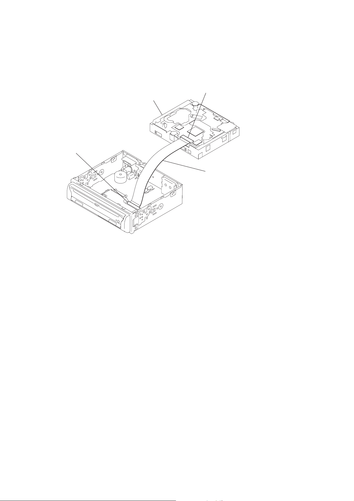
JIG ON REPAIRING
When repairing this set, etc., connect the extension cable as the figure shown below.
mechanism deck
DSP board
(CN500)
servo board
(CS201)
connect jig
(extension cable J-2502-077-1)
to the servo board (CS201)
and DSP board (CN500).
6

Location of controls
Front panel
SECTION 2
GENERAL
DVX-11A
This section is extracted from
instruction manual.
a Receptor for the card remote
commander
b Dis c slot
c DISC IN indicator
Lights up in blue when a di sc i s stored.
d Res e t bu tton
e u (p la y/pa use) button*
1
f Signal select switch
(Located on the bottom of the unit)
See “ Operati ng the unit via connected
monitor” i n the Installation/Connecti ons
manual.
g Z (e je c t) bu tto n
h OFF button*
*1 Use the tactile dot as a reference when operating
the unit.
*2 Warning when installing in a car without the
ACC (accessory) position on the ignition key
switch
Be sure to press and hold (OFF) on the unit until
the key illuminations in blue go off.
Otherwise, the unit does not turn off and this
causes battery drain.
2
DISC IN
Note
If the unit is turned off by pressing (OFF) fo r 2
seconds, press u on the unit to turn on the unit first.
In this case, the card remote commander is not
available to turn on the unit.
Tip
Yo u c an eject the disc any time whether the unit is
turned on or not, but you can insert the disc only when
the unit is turned on.
OFF
DVX-11A
8
7

DVX-11A
Card rem ote commander RM-X129
+
–
ENTER
AUDIO
SEEK
–
DISPLAY
CLEAR
0
LIST
SETUP
ANGLE
SUBTITLE
SEEK
123
456
789
TOP MENU
ALBUM
MENU
ALBUM
SOURCE
MODE
For the unit operations:
a OFF butto n
b Num b er buttons
c TOP MENU b u t to n
Displays the top menu on a DV D.
d MENU bu tto n
Displays the menu on a disc.
e O (retu rn) button
Returns to the previous di splay, or previ ous
operati on.
f u (p lay /p au s e ) b u t t o n
g DISPLAY button
Displays current pl ayback status and text
information.
h CLEAR butto n
Cancels the numbers entered.
i LIST b u t to n
Displays the list of playback i tems.
j SETUP button
Displays the Setup menu and P lay mode
menu.
k ANGLE bu tto n
Changes the v i ew i ng angl e.
l ENTER button
Applies a se tting.
m </, buttons
Move the cursor, or turn the pages.
OFFOFF
1
456
7 890
TOP MENU
ALBUM
MENU
ALBUM–
+
SOURCE
MODE
23
+
ENTER
AUDIO
SEEK–SEEK
VOLVOL
DISPLAY
CLEAR
LIST
SETUP
ANGLE
SUBTITLE
+
n ./> (p revio u s/next) buttons
o m/M (s ea rch/slow) buttons
p M ALBUM+/m ALBUM– buttons
Move the cursor, or se l ect the al bum.
q AUDIO b u tto n
Changes the audi o output.
r SUBTITLE b u t to n
Changes the subti tle l anguage.
For the Media center/receiver XAV-7W
operations:
These buttons contr ol the opti onal M edia center/
receiver XAV-7 W which i s connected to this unit.
s .S EEK–/>SEEK+ buttons
t VO L +/ – buttons
u MO DE b ut t o n
v SOURCE butto n
Note
If the unit is turned off by pressing (OFF) for 2
seconds, press u on the unit to turn on the unit first.
In this case, the card remote commander is not
available to turn on the unit.
Tip
Refer to “Replacing the lithium battery” for details on
howtoreplace the batteries.
9
8

DVX-11A
Front speaker (Left)
Subwoofer
Tiefsttonlautsprecher
Haut-parleur
d’extrêmes-graves
Subwoofer
Subwoofer
Frontlautsprecher (Links)
Enceinte avant (Gauche)
Diffusore anteriore (Sinistro)
Voorluidspreker (Links)
Rear speaker (Right)
Hecklautsprecher (Rechts)
Enceinte arrière (Droite)
Diffusore posteriore (Destro)
Achterluidspreker (Rechts)
2
Overhead monitor
Deckenmonitor
Ecran plafonnier
Monitor a sospensione
Overheadmonitor
Rear speaker (Left)
Hecklautsprecher (Links)
Enceinte arrière (Gauche)
Diffusore posteriore (Sinistro)
Achterluidspreker (Links)
3
Foot brake type
Fu§ b r e m se
Typ e pdale de frein
Fr en o a pedale
Typ e v oe tr em
Parking brake switch cord
Parkbremsenschaltleitung
Cordon du capteur du frein à main
Cavo di commutazione
Schakelsnoer van de parkeerrem
Usin g t he t ap
Das Kont akt stck
Ut ilisation de la drivation
Uso del dispositivo di accoppiamento
Het ve rb
indingselement
9
gebruiken
Parking cord (Light green) of
Parkleitung (hellgrün) von
Cordon du frein à main (vert clair)
Cavo del freno a mano (verde chiaro) di
Parkeerremkabel (lichtgroen) van
Master unit
Hauptgerät
Unité principale
Unità principale
Hoofdeenheid
Connection box
Anschlussdose
Boîtier de raccordement
Scatola di connessione
Verbindingsdoos
Hand br ake t ype
Handbr emse
Typ e f r ei n main
Fr en o a mano
Typ e h andrem
Parking brake switch cord
Parkbremsenschaltleitung
Cordon du capteur du frein à main
Cavo di commutazione
Schakelsnoer van de parkeerrem
c
2
2
2
2
Remote control sensor
Fernbedienungssensor
Capteur de la télécommande
Sensore del comando a distanza
Afstandsbedieningssensor
Front speaker (Right)
Frontlautsprecher (Rechts)
Enceinte avant (Droite)
Diffusore anteriore (Destro)
Voorluidspreker (Rechts)
Headrest Monitor
Kopfstützenmonitor
Moniteur intégré dans l’appuie-tête
Monitor per poggiatesta
Hoofdsteunmonitor
Sony DVD player DVX-11A
DVD-Player DVX-11A von Sony
Lecteur DVD DVX-11A Sony
Lettore DVD DVX-11A Sony
Sony DVD-speler DVX-11A
Parking brake switch cord
Parkbremsenschaltleitung
Cordon du capteur du frein à main
Cavo di commutazione
Schakelsnoer van de parkeerrem
2
Equi pment used in illust rations (not supplied)
4
In den Abbildungen gezeigt e Ko
Equi pements utiliss dans les illustrations (non fournis)
Apparecchiatura utilizzata nelle illustrazioni (non in dotazione)
Apparatuur die wordt gebruikt in de afbeeldingen (niet bijgeleverd)
Left
Links
Gauche
Sinistro
Links
Right
Rechts
Droite
Destro
Rechts
Left
Links
Gauche
Sinistro
Links
Right
Rechts
Droite
Destro
Rechts
*1For details on connecting the optical
cable and the optical adapter, see the
“When making a digital connection
(6)” on the reverse side.
2
For details on connecting to the parking
*
brake switch cord, and attaching the
tap 9, see “Connecting the parking
brake cord (3).”
3
*
For details, see “Attaching the remote
control sensor (8)” on the reverse side.
4
*
Use the extension cords 3 (4A)
according to the mounting location of
the unit.
5
*
For details on the remote signal
connection, see “Operating the unit via
connected monitor (5)” on the reverse
side.
Fr on t mo ni tor syste m
Fr o nt monitorsystem
Sys t m e du mo niteu r avant
Monitor ant eriore
Monitorsysteem voor
Media center main unit
Mediencenter-Hauptgerät
Unité principale du centre multimédia
Unità principale Media Center
Hoofdapparaat van het mediacentrum
Rear monit or system/ Heckmonitorsystem/Systme du
moniteur arrire/Monitor posteriore/Monitorsysteem achter
Headrest Monitor
Kopfstützenmonitor
Moniteur intégré dans l’appuie-tête
Monitor per poggiatesta
Hoofdsteunmonitor
4A
Red/Rot/Rouge
5 m
3
Rosso/Rood
Yellow/Gelb/
Jaune/Giallo/Geel
1
*
Informationen zum Anschließen des
optischen Kabels und des optischen
Adapters finden Sie unter „Wenn Sie
eine Digitalverbindung vornehmen
wollen (6)” auf der Rückseite.
2
Informationen zum Anschließen der
*
Parkbremsenschaltleitung und zum
Anbringen des Kontaktstücks 9 finden
Sie unter „Anschließen der
Parkbremsenleitung (3)“.
3
Informationen dazu finden Sie unter
*
„Anbringen des Fernbedienungssensors
(8)” auf der Rückseite.
4
Verwenden Sie je nach Montageort des
*
Geräts die Verlängerungskabel 3
(4A).
5
Informationen zum
*
Fernbedienungssignalanschluss finden
Sie unter „Bedienen des Geräts über
den angeschlossenen Monitor (5)” auf
der Rückseite.
mponenten (nicht mitgeliefert)
Connection box
Anschlussdose
Boîtier de raccordement
Scatola di connessione
Verbindingsdoos
Connection box
Anschlussdose
Boîtier de raccordement
Scatola di connessione
Verbindingsdoos
Fuse (1 A)
Sicherung (1 A)
Fusible (1 A)
Fusibile (1 A)
Zekering (1 A)
Fuse (10 A)
Sicherung (10 A)
Fusible (10 A)
Fusibile (10 A)
Zekering (10 A)
Front speaker
Frontlautsprecher
Enceinte avant
Diffusore anteriore
Voorluidspreker
Optical cable RC-97/98 (not supplied)*
Optisches Kabel RC-97/98 (nicht mitgeliefert)*
Câble optique RC-97/98 (non fourni)*
Cavo ottico RC-97/98 (non in dotazione)*
Optische kabel RC-97/98 (niet bijgeleverd)*
5 m
4
RCA pin cord
(not supplied)
Cinchkabel
(nicht mitgeliefert)
Cordon à broche RCA
(non fourni)
Cavo a piedini RCA
(non in dotazione)
Tulpstekkersnoer
(niet bijgeleverd)
5
*
1
*
Pour plus de détails sur le raccordement
du câble optique et de l’adaptateur
optique, reportez-vous à la section « En
cas de raccordement numérique (6) »
au verso.
2
Pour plus de détails sur le raccordement
*
du cordon du capteur du frein à main et
de la fixation de la dérivation 9,
reportez-vous à la section
« Raccordement du cordon du frein à
main (3) ».
3
Pour plus de détails, reportez-vous à la
*
section « Fixation du capteur de la
télécommande (8) » au verso.
4
Utilisez les cordons prolongateurs 3
*
(4A) selon l’emplacement de montage
de l’appareil.
5
Pour plus de détails sur le raccordement
*
du signal de la télécommande,
reportez-vous à la section « Utilisation
de l’appareil via le moniteur raccordé
(5) » au verso.
Rear speaker
Hecklautsprecher
Enceinte arrière
Diffusore posteriore
Achterluidspreker
1
1
1
1
1
FRONT AUDIO/
VIDEO OUT
FRONT
REAR
VIDEO
R
L
OUT
AUDIO OUT
REAR AUDIO/
VIDEO OUT
Remote control sensor*
Fernbedienungssensor*
Capteur de la télécommande*
Sensore del comando a distanza*
Afstandsbedieningssensor*
3
3
5
0.5 m
1
*
Per ulteriori informazioni sulle modalità
di collegamento del cavo ottico e
dell’adattatore ottico, vedere
“Collegamento digitale (6)” sul lato
opposto.
2
Per ulteriori informazioni sulle modalità
*
di collegamento del cavo di
commutazione del freno a mano e di
installazione del dispositivo di
accoppiamento 9, vedere la sezione
relativa al “Collegamento del cavo del
freno a mano (3)”.
3
Per ulteriori informazioni, vedere
*
“Installazione del sensore del comando
a distanza (8)” sul lato opposto.
4
Utilizzare le prolunghe 3 (4A) in base
*
alla posizione di montaggio
dell’apparecchio.
5
Per ulteriori informazioni sull’uso del
*
segnale remoto, vedere “Uso
dell’apparecchio mediante il monitor
collegato (5)” sul lato opposto.
REMOTE
SIGNAL IN
3
3
3
6
5 m
Optical adapter XA-D211 (not supplied)*
Optischer Adapter XA-D211 (nicht mitgeliefert)*
Adaptateur optique XA-D211 (non fourni)*
Adattatore ottico XA-D211 (non in dotazione)*
Optische adapter XA-D211 (niet bijgeleverd)*
DIGITAL OUT
DIGITAL OUT
REMOTE
SIGNAL
IN
Black
Schwarz
2
Noir
Nero
Zwart
Red
Rot
Rouge
Rosso
Rood
Yellow
Gelb
Jaune
Giallo
Geel
Light green
Hellgrün
Vert clair
Verde chiaro
Lichtgroen
1
*
2
*
3
*
4
*
5
*
Subwoofer
Tiefsttonlautsprecher
Haut-parleur d’extrêmes-graves
Subwoofer
Subwoofer
0.45 m
0.25 m
0.25 m
Fuse (10 A)
Sicherung (10 A)
Fusible (10 A)
Fusibile (10 A)
Zekering (10 A)
3.0 m
Zie "Een digitale aansluiting maken
(6)" op de achterkant voor meer
informatie over het aansluiten van de
optische kabel en de optische adapter.
Zie "Parkeerremkabel aansluiten (3)"
voor meer informatie over het
aansluiten op het schakelsnoer van de
parkeerrem en het bevestigen van het
verbindingselement 9.
Zie "Afstandsbedieningssensor
bevestigen (8)" op de achterzijde voor
meer informatie.
Gebruik de verlengsnoeren 3 (4A)
afhankelijk van de installatiepositie van
het apparaat.
Zie "Het apparaat bedienen met de
aangesloten monitor (5)" op de
achterzijde voor meer informatie over
het infraroodsignaal.
4
*
4
*
2
9*
1
1
1
1
1
Cautions
•This unit is designed for negative ground 12 V DC
operation only.
•Do not pinch wires under screws, or in moving parts (e.g.,
seat railing).
•Before making connections, turn the car ignition off to
avoid short circuits.
•Connect the yellow and red power input leads only after
all other leads have been connected.
•Run all ground wires to a common ground point.
•Be sure to insulate any loose unconnected wires with
electrical tape for safety.
•The use of optical instruments with this product will
increase the risk of eye injury.
•Control adjustments and procedures other than those
specified herein may result in hazardous radiation
exposure.
•For your safety, the monitor connected to the FRONT
VIDEO OUT can only be viewed when the car is stopped
and the parking brake applied.
Be sure to connect the parking cord (Light green) of 2 to
the car’s parking brake switch cord.
Notes on the power supply cord (yellow)
•When connecting this unit in combination with other stereo
components, the connected car circuit’s rating must be
higher than the sum of each component’s fuse.
•When no car circuits are rated high enough, connect the
unit directly to the battery.
Parts Iist (1)
The numbers in the list are keyed to those in the instructions.
Installation diagram (2)
Example:
When installing under the passenger seat.
Note
All the equipment other than the Sony DVD player DVX-11A and
the remote control sensor is not supplied.
Connecting the parking brake cord (3)
Be sure to connect the parking cord (Light green) of 2 to the
parking brake switch cord. The mounting position of the
parking brake switch cord depends on your car. Consult
your car dealer or your nearest Sony dealer for further
details.
Using the tap
Attach the tap 9 to the end of the parking cord (Light green)
of 2 and the parking brake switch cord.
Note
If the parking brake switch cord is too thin, connect the parking
cord (Light green) of 2 to the parking brake switch cord directly
without using the tap 9.
Connection diagram (4)
1 To a metal surface of the car
First connect the black ground lead, then connect the yellow
and red power input leads.
2 To the +12 V power terminal which is energized in the
accessory position of the ignition key switch
Note
If there is no accessory position, connect to the +12 V power
(battery) terminal which is energized at all times.
Be sure to connect the black ground lead to a metal surface of
the car first.
3 To the +12 V power terminal which is energized at all times
Be sure to connect the black ground lead to a metal surface of
the car first.
4 To the parking brake switch cord
5 To a digital amplifier or audio device
Connect the optical cable RC-97/98 (not supplied), etc., to a
digital amplifier or audio device equipped with a Dolby digital
decoder.
Sicherheitshinweise
•Dieses Gerät eignet sich nur für den Betrieb an 12 V
Gleichstrom (negative Erdung).
•Achten Sie darauf, dass die Leitungen nicht unter einer
Schraube oder zwischen beweglichen Teilen wie z. B. in
einer Sitzschiene eingeklemmt werden.
•Schalten Sie, bevor Sie irgendwelche Anschlüsse
vornehmen, die Zündung des Fahrzeugs aus, um
Kurzschlüsse zu vermeiden.
•Schließen Sie die gelbe und die rote
Stromversorgungsleitung erst an, wenn alle anderen
Leitungen angeschlossen wurden.
•Verbinden Sie alle Massedrähte mit einem
gemeinsamen Massepunkt.
•Aus Sicherheitsgründen müssen alle losen, nicht
angeschlossenen Drähte mit Isolierband abisoliert werden.
•Die Verwendung optischer Instrumente zusammen mit
diesem Produkt stellt ein Gesundheitsrisiko für die Augen
dar.
•Wenn Sie die vorliegenden Anweisungen zum Einstellen
und Vorgehen nicht beachten, kann gefährliche Strahlung
austreten.
•Aus Sicherheitsgründen erscheint auf dem Monitor, der an
FRONT VIDEO OUT angeschlossen ist, nur ein Bild, wenn
der Wagen steht und die Parkbremse angezogen ist.
Die Parkleitung (hellgrün) von 2 muss unbedingt an die
Parkbremsenschaltleitung des Autos angeschlossen
werden.
Hinweise zum Stromversorgungskabel (gelb)
•Wenn Sie dieses Gerät zusammen mit anderen
Stereokomponenten anschließen, muss der
Autostromkreis, an den die Geräte angeschlossen sind, eine
höhere Leistung aufweisen als die Summe der Sicherungen
der einzelnen Komponenten.
•Wenn kein Autostromkreis eine so hohe Leistung aufweist,
schließen Sie das Gerät direkt an die Batterie an.
Teileliste (1)
Die Nummern in der Liste entsprechen denen in der
Anleitung.
Installationsdiagramm (2)
Beispiel:
Installation unter dem Beifahrersitz.
Hinweis
Alle Geräte außer dem DVD-Player DVX-11A von Sony und dem
Fernbedienungssensor sind nicht mitgeliefert.
Anschließen der Parkbremsenleitung
(
3
)
Die Parkleitung (hellgrün) von 2 muss unbedingt an die
Parkbremsenschaltleitung angeschlossen werden. Die
Montageposition der Parkbremsenschaltleitung ist von
Fahrzeugmodell zu Fahrzeugmodell unterschiedlich.
Weitere Informationen erhalten Sie bei Ihrem
Fahrzeughändler oder Ihrem Sony-Händler.
Das Kontaktstück
Verbinden Sie das Kontaktstück 9 mit dem Ende der
Parkleitung (hellgrün) von 2 und der
Parkbremsenschaltleitung.
Hinweis
Ist die Parkbremsenschaltleitung zu dünn, verbinden Sie die
Parkleitung (hellgrün) von 2 direkt mit der
Parkbremsenschaltleitung, ohne das Kontaktstück 9 zu
benutzen.
Anschlussdiagramm (4)
1 An eine Metalloberfläche des Wagens
Schließen Sie zuerst die schwarze Masseleitung und dann die
gelbe und rote Stromversorgungsleitung an.
2 An den +12-V-Stromversorgungsanschluss, an dem Spannung
anliegt, wenn sich der Zündschlüssel in der Zubehörposition
befindet
Hinweis
Wenn das Zündschloss keine Zubehörposition (ACC oder I)
aufweist, schließen Sie die Leitung an den +12-VStromversorgungsanschluss an, an dem immer Spannung
anliegt.
Sie müssen aber zuerst die schwarze Masseleitung an eine
Metalloberfläche des Wagens anschließen.
3 An den +12-V-Stromversorgungsanschluss, an dem immer
Spannung anliegt
Sie müssen aber zuerst die schwarze Masseleitung an eine
Metalloberfläche des Wagens anschließen.
4 An die Parkbremsenschaltleitung
5 An digitalen Verstärker oder Audiogerät
Schließen Sie das optische Kabel RC-97/98 (nicht mitgeliefert)
usw. an einen digitalen Verstärker oder ein Audiogerät an, das
mit einem Dolby Digital-Decoder ausgestattet ist.
Précautions
•Cet appareil est uniquement conçu pour fonctionner sur
courant continu de 12 V avec masse négative.
•Evitez de fixer des vis sur les câbles ou de coincer ceux-ci
dans des pièces mobiles (par exemple, armature de siège).
•Avant d’effectuer les raccordements, coupez le moteur
pour éviter les courts-circuits.
•Branchez les cordons d’alimentation jaune et rouge
uniquement une fois que tous les autres cordons ont été
raccordés.
•Rassemblez tous les fils de terre en un point de masse
commun.
•Pour plus de sécurité, veillez à isoler avec du chatterton
tout fil lâche non raccordé.
•L’utilisation d’instruments optiques avec ce produit peut
augmenter les risques de lésions oculaires.
•L’application de réglages de commande et de procédures
autres que ceux spécifiés dans ce manuel risquent de
provoquer une exposition à des radiations dangereuses.
•Pour votre sécurité, le moniteur raccordé à la prise FRONT
VIDEO OUT ne fonctionne que lorsque la voiture est
arrêtée et le frein à main serré.
Pensez à raccorder le cordon du frein (vert clair) 2 au
cordon du capteur du frein à main de la voiture.
Remarques sur le cordon d’alimentation (jaune)
•Lorsque cet appareil est raccordé à d’autres appareils
stéréo, la valeur nominale des circuits de la voiture
raccordée doit être supérieure à la somme des fusibles de
chaque appareil.
•Si aucun circuit n’est assez puissant, raccordez directement
l’appareil à la batterie.
Listes des composants (1)
Les numéros de la liste correspondent à ceux des
instructions.
Schéma d’installation (2)
Exemple :
En cas d’installation sous le siège passager.
Remarque
Tous les équipements autres que le lecteur DVD DVX-11A Sony et
le capteur de la télécommande ne sont pas fournis.
Raccordement du cordon du frein à
main (
3
)
Veillez à raccorder le cordon du frein (vert clair) 2 au
cordon du capteur du frein à main. La position de montage
du cordon du capteur du frein à main varie selon la voiture.
Consultez votre concessionnaire automobile ou votre
revendeur Sony le plus proche pour obtenir plus de détails.
Utilisation de la dérivation
Raccordez la dérivation 9 à l’extrémité du cordon du frein
(vert clair) 2 au cordon du capteur du frein à main.
Remarque
Si le cordon du capteur du frein à main est trop fin, raccordez le
cordon du frein (vert clair) 2 au cordon du capteur du frein à
main directement sans utiliser la dérivation 9.
Schéma de raccordement (4)
1 Vers une surface métallique de la voiture
Commencez par raccorder le cordon de terre, puis raccordez
les cordons d’alimentation jaune et rouge.
2 Vers la borne d’alimentation +12 V alimentée en position
accessoires du contact
Remarque
Si la voiture ne possède pas de position accessoires, raccordez
l’appareil à la borne d’alimentation + 12 V (batterie)
alimentée en continu.
Commencez par raccorder le cordon de terre noir à une
surface métallique de la voiture.
3 Vers la borne d’alimentation +12 V alimentée en continu
Commencez par raccorder le cordon de terre noir à une
surface métallique de la voiture.
4 Vers le cordon du capteur du frein à main
5 Vers un amplificateur numérique ou un appareil audio
Raccordez le câble optique RC-97/98 (non fourni), etc., à un
amplificateur numérique ou à un appareil audio doté d’un
décodeur Dolby digital.
Attenzione
•Il presente apparecchio è stato progettato per il solo uso a
12 V CC con massa negativa.
•Evitare che i cavi rimangano bloccati dalle viti o incastrati
nelle parti mobili (ad esempio, nelle guide scorrevoli dei
sedili).
•Prima di effettuare i collegamenti, spegnere il motore
dell’auto onde evitare di causare cortocircuiti.
•Collegare i cavi di ingresso dell’alimentazione giallo e
rosso solo dopo che tutti gli altri cavi sono stati collegati.
•Portare tutti i cavi di massa ad un punto di massa
comune.
•Per motivi di sicurezza, accertarsi di isolare eventuali cavi
liberi non collegati mediante apposito nastro.
•L’uso di strumenti ottici con il presente apparecchio può
causare problemi agli occhi.
•Il controllo di regolazioni e procedure, diverse da quelle
specificate nella presente documentazione, potrebbe
determinare l’esposizione a radiazioni pericolose.
•Per motivi di sicurezza, il monitor collegato all’uscita
FRONT VIDEO OUT può essere utilizzato solo se l’auto
non è in movimento e il freno a mano è stato azionato.
Assicurarsi di collegare il cavo del freno a mano (verde
chiaro) di 2 al cavo di commutazione del freno a mano.
Note sul cavo di alimentazione (giallo)
•Se il presente apparecchio viene collegato con altri
componenti stereo, la potenza nominale dei circuiti
dell’auto deve essere superiore a quella prodotta dalla
somma dei fusibili di ciascun componente.
•Se la potenza nominale dei circuiti dell’auto non è
sufficiente, collegare l’apparecchio direttamente alla
batteria.
Elenco delle parti (1)
I numeri indicati nell’elenco corrispondono a quelli riportati
nelle istruzioni.
Schema di installazione (2)
Esempio:
Installazione sotto il sedile del passeggero.
Nota
Eventuali apparecchi diversi dal lettore DVD DVX-11A Sony e dal
sensore del comando a distanza non sono in dotazione.
Collegamento del cavo del freno a
mano (
3
)
Assicurarsi di collegare il cavo del freno a mano (verde
chiaro) di 2 al cavo di commutazione del freno a mano
dell’auto. La posizione di montaggio del cavo di
commutazione del freno a mano varia in base all’auto. Per
ulteriori informazioni, consultare l’autoconcessionaria di
fiducia o il più vicino rivenditore Sony.
Uso del dispositivo di accoppiamento
Applicare il dispositivo di accoppiamento 9 all’estremità
del cavo del freno a mano (verde chiaro) di 2 e del cavo di
commutazione del freno a mano.
Nota
Se il cavo di commutazione del freno a mano è troppo sottile,
collegare direttamente il cavo del freno a mano (verde chiaro) di
2 al cavo di commutazione del freno a mano senza utilizzare il
dispositivo di accoppiamento 9.
Schema di collegamento (4)
1 Ad una superficie metallica dell’auto
Collegare innanzitutto il cavo di massa nero, quindi collegare i
cavi di ingresso dell’alimentazione giallo e rosso.
2 Al terminale di alimentazione da +12 V che viene alimentato
nella posizione accessoria dell’interruttore di accensione
dell’auto
Nota
Se l’auto è priva della posizione accessoria, collegare il
terminale di alimentazione da +12 V (batteria) che viene
sempre alimentato.
Assicurarsi di collegare innanzitutto il cavo di massa nero ad
una superficie metallica dell’auto.
3 Al terminale di alimentazione da +12 V che viene sempre
alimentato
Assicurarsi di collegare innanzitutto il cavo di massa nero ad
una superficie metallica dell’auto.
4 Al cavo di commutazione del freno a mano
5 Ad un amplificatore digitale o dispositivo audio
Collegare il cavo ottico RC-97/98 (non in dotazione) e simili ad
un amplificatore digitale o ad un dispositivo audio dotato di
decodificatore Dolby Digital.
Waarschuwingen
•Dit apparaat is alleen ontworpen voor werking op 12 V
gelijkstroom, negatief geaard.
•Zorg ervoor dat de kabels niet onder schroeven of in
bewegende delen (zoals de rug van de stoel) klem komen
te zitten.
•Voordat u aansluitingen maakt, moet u de motor
uitschakelen om kortsluiting te voorkomen.
•Sluit de gele en rode netsnoeren pas aan als alle andere
kabels zijn aangesloten.
•Sluit alle aardingsdraden aan op een
gemeenschappelijk aardpunt.
•Voorzie niet aangesloten draden om veiligheidsredenen
altijd van isolatietape.
•De optische instrumenten in dit apparaat vergroten de
kans op oogletsel.
•Aanpassingen in de bediening en procedures die anders
zijn dan die in dit document worden beschreven, kunnen
gevaarlijke blootstelling aan straling tot gevolg hebben.
•Voor uw eigen veiligheid kan de monitor die is aangesloten
op FRONT VIDEO OUT, alleen worden bekeken als de
auto stilstaat en de parkeerrem wordt gebruikt.
Sluit de parkeerremkabel (lichtgroen) van 2 aan op het
schakelsnoer van de parkeerrem van de auto.
Opmerkingen over het netsnoer (geel)
•Als u dit apparaat installeert in combinatie met andere
stereo-onderdelen, moet het vermogen van de aangesloten
stroomkring hoger zijn dan de som van de zekeringen van
elk onderdeel.
•Wanneer het vermogen ontoereikend is, moet u het
apparaat rechtstreeks aansluiten op de accu.
Lijst met onderdelen (1)
De cijfers in de lijst komen overeen met de cijfers in de
instructies.
Installatieschema (2)
Voorbeeld:
Het apparaat installeren onder de passagiersstoel.
Opmerking
Behalve de Sony DVD-speler DVX-11A en de
afstandsbedieningssensor is de rest van de apparatuur niet
bijgeleverd.
Parkeerremkabel aansluiten (3)
Sluit de parkeerremkabel (lichtgroen) van 2 aan op het
schakelsnoer van de parkeerrem. De plaats waar het
schakelsnoer van de parkeerrem moet worden geplaatst, is
afhankelijk van de auto. Raadpleeg de autohandelaar of de
dichtstbijzijnde Sony-handelaar voor meer informatie.
Het verbindingselement gebruiken
Maak het verbindingselement 9 vast aan het uiteinde van
de parkeerremkabel (lichtgroen) van 2 en het schakelsnoer
van de parkeerrem.
Opmerking
Als het schakelsnoer van de parkeerrem te dun is, verbindt u de
parkeerremkabel (lichtgroen) van 2 rechtstreeks met het
schakelsnoer van de parkeerrem zonder het verbindingselement
9 te gebruiken.
Aansluitschema (4)
1 Naar een metalen oppervlak van de auto
Sluit eerst de zwarte aardingsdraad aan en vervolgens de gele
en rode netsnoeren.
2 Naar de +12 V voedingsaansluiting die stroom ontvangt in de
accessoirepositie (ACC) van het contactslot
Opmerking
Als er geen accessoirepositie (ACC) is, moet u verbinding
maken met de +12 V voedingsaansluiting (accu) die altijd
stroom ontvangt.
Sluit de zwarte aardingsdraad eerst aan op een metalen
oppervlak van de auto.
3 Naar de +12 V voedingsaansluiting die altijd stroom ontvangt
Sluit de zwarte aardingsdraad eerst aan op een metalen
oppervlak van de auto.
4 Naar het schakelsnoer van de parkeerrem
5 Naar een digitale versterker of audioapparaat
Sluit de optische kabel RC-97/98 (niet bijgeleverd) aan op een
digitale versterker of audioapparaat met een Dolby digital
decoder.
9

DVX-11A
56
Sig na l s el ect swi tch
Sig n a l w h l sch al t er
Sl e ct e u r du sig nal
Sel e ttore del segnale
Scha k e l aar voor
sign aal sel ect i e
XVM-R75
OTHERS
7
Precautions
•Choose the installation location carefully so that the unit will not interfere with
normal driving operations.
•Avoid installing the unit in areas subject to dust, dirt, excessive vibration, or high
temperatures, such as in direct sunlight or near heater ducts.
•Use only the supplied mounting hardware for a safe and secure installation.
Mounting angle adjustment
Adjust the mounting angle to less than 20°.
Operating the unit via connected monitor (5)
You can operate the unit via the monitor when XVM-R75, XVM-R70 or XVM-H65 is
connected.
Before installing the unit, set the signal select switch to “XVM-R75” when XVM-R75
is connected, and set to “OTHERS” when a monitor other than XVM-R75 is
connected.
Tip
If the tuner unit XT-P50 is connected to this unit together with XVM-R75, set the signal
switch to “OTHERS.”
When making a digital connection (6)
When connecting to a digital amplifier or audio device equipped with a Dolby
digital decoder, connect the optical cable to the optical adaptor first, then connect
the optical adapter to the DIGITAL OUT on the back panel. Before securing the
cables with the fitting qa, connect the L-type plug of the connecting cord 6 to the
remote sensor first.
Notes
•When you wish to disconnect the optical cable, simply push in on both sides of the
connector.
•Be sure to keep the protective cap in a safe place for future use.
•Do not bend the optical cable too much. If it is bent in an arc of less than 10 cm in
diameter, sound may not be reproduced.
•Be sure to use an optical cable (not supplied) and an optical adapter (not supplied)
designed for Sony car audio systems.
•Make sure that the optical cable is securely plunged to the optical adapter when making
connection.
•Make sure the optical cable does not get compressed or constricted in any way by
surrounding objects.
•Never let the coupler parts of the connectors get scratched or become contaminated with
dirt.
Mounting example (7)
Horizontal installation
When you install the unit, be careful not to damage wiring or equipment on the
other side of the mounting surface.
Attaching the remote control sensor (8)
When installing the unit under the passenger seat, or in a car trunk, use remote
control sensor 5 as a signal receptor.
Before installing the remote control sensor, determine the maximum operating
distance of the card remote commander. The card remote commander can be used
up to approximately 3 m from the signal receptor, in a conical area spreading
roughly 15° from the signal transmitter.
Note
Clean the mounting surface before attaching the double-sided tape qs and cord clamps qd.
For your safety
After installing the remote control sensor, use cord clamps qd to secure the cord to a
place where it does not interfere with normal driving operation. It is very dangerous
if the cord becomes tangled with the gearshift lever during driving.
Warning when installing in a car without ACC
(accessory) position on the ignition key switch
Be sure to press and hold (OFF) on the unit until the key illuminations in blue
go off after turning off the engine.
When you press (OFF) only momentarily, the unit does not turn off and this causes
battery wear.
Reset button (9)
When the installation and connections are completed, be sure to press the reset
button with a ballpoint pen, etc., to reset the unit.
Optical cable RC-97/98 (not supplied)
Optisches Kabel RC-97/98 (nicht mitgeliefert)
Câble optique RC-97/98 (non fourni)
Cavo ottico RC-97/98 (non in dotazione)
Optische kabel RC-97/98 (niet bijgeleverd)
Optical adapter XA-D211 (not supplied)
6
Optischer Adapter XA-D211 (nicht mitgeliefert)
Adaptateur optique XA-D211 (non fourni)
Adattatore ottico XA-D211 (non in dotazione)
Optische adapter XA-D211 (niet bijgeleverd)
8
1
7
3.5 mm
Sicherheitsmaßnahmen
•Wählen Sie den Einbauort sorgfältig so aus, dass das Gerät beim Fahren nicht
hinderlich ist.
•Installieren Sie das Gerät nicht an einer Stelle, an der es Staub, Schmutz,
übermäßigen Erschütterungen oder hohen Temperaturen ausgesetzt ist, wie z. B. in
direktem Sonnenlicht oder in der Nähe der Heizung.
•Verwenden Sie ausschließlich die mitgelieferten Montageteile. Nur mit diesen
Teilen lässt sich das Gerät sicher montieren.
Montagewinkel
Achten Sie darauf, dass der Montagewinkel geringer ist als 20°.
Bedienen des Geräts über den angeschlossenen Monitor (5)
Sie können das Gerät über den Monitor bedienen, wenn der XVM-R75, XVM-R70
oder XVM-H65 angeschlossen ist.
Stellen Sie den Signalwählschalter vor dem Installieren des Geräts auf „XVM-R75“,
wenn der XVM-R75 angeschlossen ist, bzw. auf „OTHERS“, wenn ein anderer
Monitor als der XVM-R75 angeschlossen ist.
Tipp
Wenn die Tunereinheit XT-P50 zusammen mit dem XVM-R75 an dieses Gerät angeschlossen
ist, stellen Sie den Signalwählschalter auf „OTHERS“.
Wenn Sie eine Digitalverbindung vornehmen wollen (6)
Wenn Sie einen digitalen Verstärker oder ein Audiogerät anschließen wollen, das
mit einem Dolby Digital-Decoder ausgestattet ist, verbinden Sie das optische
Kabel zuerst mit dem optischen Adapter und schließen Sie dann den optischen
Adapter an DIGITAL OUT an der Rückseite an. Bevor Sie die Kabel mit der
Halterungqa sichern, verbinden Sie den L-förmigen Stecker des
Verbindungskabels6 mit dem Fernbedienungssensor.
Hinweise
•Wenn Sie das optisches Kabel lösen wollen, drücken Sie einfach auf beide Seiten des
Steckers.
•Heben Sie die Schutzkappe sorgfältig auf, damit Sie sie bei Bedarf erneut anbringen
können.
•Biegen Sie das optisches Kabel nicht zu stark. Der minimal zulässige Krümmungsradius
beträgt 10 cm. Bei kleinerem Krümmungsradius wird möglicherweise kein Ton
ausgegeben.
•Verwenden Sie unbedingt ein optisches Kabel (nicht mitgeliefert) und einen optischen
Adapter (nicht mitgeliefert), die für Autoanlagen von Sony geeignet sind.
•Vergewissern Sie sich beim Herstellen der Verbindung, dass das optische Kabel fest am
optischen Adapter angeschlossen ist.
•Achten Sie darauf, dass das optisches Kabel nicht durch andere Teile gequetscht oder
eingeklemmt wird.
•Die Steckerteile des Anschlusses dürfen unter keinen Umständen verkratzt oder
verschmutzt werden.
Montagebeispiel (7)
Horizontaler Einbau
Achten Sie beim Installieren des Geräts darauf, dass keine Kabel und keine anderen
Teile auf der anderen Seite der Montagestelle beschädigt werden.
Anbringen des Fernbedienungssensors (8)
Wenn Sie das Gerät unter dem Beifahrersitz oder im Kofferraum installieren,
verwenden Sie den Fernbedienungssensor 5 als Signalempfänger.
Überprüfen Sie vor dem Installieren des Fernbedienungssensors die maximale
Reichweite der Kartenfernbedienung. Die Kartenfernbedienung kann in einem
Abstand von bis zu etwa 3 m zum Signalempfänger und in einem Winkel von ca. 15°
vom Signalsender verwendet werden.
Hinweis
Reinigen Sie die Montagestelle, bevor Sie das doppelseitige Klebeband qs und die
Kabelklemmenqd anbringen.
Sicherheitshinweis
Sichern Sie nach dem Installieren des Fernbedienungssensors das Kabel mit
Kabelklemmenqd so, dass es beim Fahren nicht hinderlich ist. Wenn sich das Kabel
während der Fahrt am Schalthebel verfängt, kann es zu sehr gefährlichen
Situationen kommen.
Warnhinweis zur Installation des Geräts in einem Auto
mit Zündschloss ohne Zubehörposition ACC oder I
Nachdem Sie den Motor ausgeschaltet haben, halten Sie unbedingt (OFF) am
Gerät gedrückt, bis die blaue Tastenbeleuchtung erlischt.
Wenn Sie (OFF) nur kurz drücken, wird das Gerät nicht ausgeschaltet und der
Autobatterie wird Strom entzogen.
Rücksetztaste (9)
Wenn Sie das Gerät eingebaut und alle Anschlüsse vorgenommen haben, drücken
Sie die Rücksetztaste mit einem Kugelschreiber oder ähnlichem, um das Gerät
zurückzusetzen.
8
7
1
c
0
qa
Précautions
•Choisissez soigneusement l’emplacement de l’installation afin que l’appareil ne
gêne pas une position normale de conduite.
•Evitez d’installer l’appareil dans un endroit exposé à la poussière, à la saleté, à des
vibrations excessives ou à des températures élevées comme en plein soleil ou à
proximité de conduits de chauffage.
•Pour garantir un montage sûr, n’utilisez que le matériel fourni.
Réglages de l’angle de montage
Ajustez l’inclinaison à un angle inférieur à 20°.
Utilisation de l’appareil via le moniteur raccordé (5)
Vous pouvez faire fonctionner le lecteur via le moniteur lorsque XVM-R75,
XVM-R70 ou XVM-H65 est raccordé.
Avant d’installer le lecteur, réglez le sélecteur du signal sur «XVM-R75 » lorsque
XVM-R75 est raccordé et sur «OTHERS » lorsqu’un moniteur autre que XVM-R75
est raccordé.
Conseil
Si le tuner XT-P50 est raccordé à cet appareil en même temps que XVM-R75, réglez le
sélecteur du signal sur «OTHERS ».
En cas de raccordement numérique (6)
Lorsque vous raccordez un amplificateur numérique ou un appareil audio doté
d’un décodeur Dolby digital, commencez par raccorder le câble optique à
l’adaptateur optique, puis l’adaptateur optique à la prise DIGITAL OUT située sur
le panneau arrière. Avant de fixer les câbles avec l’attache qa, commencez par
raccorder la prise en forme de L du cordon de raccordement 6 au capteur de la
télécommande.
Remarques
•Si vous souhaitez débrancher le câble optique, appuyez simplement sur les deux côtés du
connecteur.
•Veillez à conserver le capuchon de protection dans un endroit sûr afin de pouvoir l’utiliser
ultérieurement.
•Ne pliez pas trop le câble optique. S’il est plié selon un arc inférieur à 10cm de diamètre,
il est possible qu’aucun son ne soit émis.
•Veillez à utiliser un câble optique (non fourni) et un adaptateur optique (non fourni)
compatibles avec les systèmes audio pour automobiles de Sony.
•Vérifiez que le câble optique est correctement inséré dans l’adaptateur optique lorsque
vous procédez au raccordement.
•Vérifiez que le câble optique n’est pas trop compressé ou gêné de quelque façon que ce
soit par les objets environnants.
•Faites en sorte que les parties du coupleur des connecteurs ne soient jamais éraflées ou
souillées.
Exemple de montage (7)
Installation à l’horizontale
Lorsque vous installez l’appareil, veillez à ne pas endommager le câblage ou
l’équipement situé de l’autre côté de la surface de montage.
Fixation du capteur de la télécommande (8)
Lorsque vous installez l’appareil sous le siège passager ou dans le coffre, utilisez le
capteur de la télécommande 5 comme capteur du signal.
Avant d’installer le capteur de la télécommande, déterminez la distance de
fonctionnement maximale de la télécommande-carte. Elle peut être utilisée jusqu’à
environ 3m du capteur du signal, dans une zone en forme de cône s’étendant
jusqu’à environ 15° du transmetteur du signal.
Remarque
Nettoyez la surface avant de fixer l’adhésif double face qs et l’attache-fils qd.
Pour votre sécurité
Après avoir installé le capteur de la télécommande, utilisez des attaches-fils qd afin
de fixer le cordon dans un endroit où il ne gêne pas une position de conduite
normale. Si le cordon se prenait dans le levier de vitesse pendant la conduite, ceci
pourrait être très dangereux.
Avertissement en cas d’installation dans une voiture
dont le contact ne comporte pas de position ACC
(accessoires)
Appuyez sur la touche (OFF) de l’appareil et maintenez-la enfoncée jusqu’à ce
que l’éclairage bleu des touches disparaisse, après avoir coupé le moteur.
Si vous n’appuyez que brièvement sur (OFF), l’appareil ne s’éteint pas, ce qui
provoque la décharge de la batterie.
Touche de réinitialisation (9)
Lorsque l’installation et les raccordements sont terminés, appuyez sur la touche de
réinitialisation avec un stylo à bille, pour réinitialiser l’appareil.
8
9
Signal receptor
Signalempfänger
Signal transmitter
Capteur de signal
Signalsender
Ricevitore del segnale
Transmetteur de signal
Signaalontvanger
Trasmettitore del segnale
Signaalzender
15º
15º
Card remote commander
Kartenfernbedienung
Télécommande-carte
Telecomando a scheda
Kaartafstandsbediening
Approx. 3 m
ca. 3 m
Environ 3m
Circa 3 m
Ongeveer 3 m
Precauzioni
•Scegliere con attenzione la posizione per l’installazione in modo che l’apparecchio
non interferisca con le normali operazioni di guida del conducente.
•Evitare di installare l’apparecchio in luoghi soggetti a polvere, sporco, vibrazioni
eccessive o temperature elevate, come alla luce solare diretta o al getto di aria calda
dell’impianto di riscaldamento.
•Per un’installazione stabile e sicura, utilizzare esclusivamente il materiale di
montaggio in dotazione.
Regolazione dell’angolo di montaggio
Regolare l’angolo di montaggio in modo che sia inferiore a 20°.
Uso dell’apparecchio mediante il monitor collegato (5)
É possibile utilizzare l’apparecchio mediante il monitor se è collegato uno dei
seguenti modelli: XVM-R75, XVM-R70 o XVM-H65.
Prima di installare l’apparecchio, impostare il selettore del segnale su “XVM-R75” se
è collegato un monitor XVM-R75 oppure impostarlo su “OTHERS” se è collegato un
altro monitor.
Suggerimento
Se il sintonizzatore XT-P50 è collegato al presente apparecchio contemporaneamente al
monitor XVM-R75, impostare il selettore del segnale su “OTHERS”.
Collegamento digitale (6)
Per il collegamento di un amplificatore digitale o di un dispositivo audio dotato di
decodificatore Dolby Digital, collegare innanzitutto il cavo ottico all’adattatore
ottico, quindi l’adattatore ottico a DIGITAL OUT sul pannello posteriore. Prima di
fissare i cavi mediante il giunto qa, collegare innanzitutto la spina di tipo a L del
cavo di collegamento 6 al sensore del comando a distanza.
Note
•Per scollegare il cavo ottico, è sufficiente premere verso l’interno entrambi i lati del
connettore.
•Assicurarsi di conservare il cappuccio di protezione in un luogo sicuro per un eventuale
uso futuro.
•Non piegare eccessivamente il cavo ottico. Se il cavo viene piegato a formare un cerchio di
diametro inferiore a 10 cm, è possibile che l’audio non venga riprodotto.
•Assicurarsi di utilizzare un cavo ottico (non in dotazione) e un adattatore ottico (non in
dotazione) progettato per le autoradio Sony.
•Per il collegamento, assicurarsi che il cavo ottico sia collegato in modo saldo all’adattatore
ottico.
•Assicurarsi che il cavo ottico non venga compresso in alcun modo da oggetti circostanti.
•Evitare che le parti di accoppiamento dei connettori vengano graffiate o contaminate da
sporcizia.
Esempio di montaggio (7)
Installazione orizzontale
Durante l’installazione dell’apparecchio, prestare attenzione a non danneggiare cavi
o apparecchiature situati sulla parte opposta della superficie di montaggio.
Installazione del sensore del comando a distanza (8)
Per l’installazione dell’apparecchio sotto il sedile del passeggero o nel bagagliaio
dell’auto, utilizzare il sensore del comando a distanza 5 come ricevitore del segnale.
Prima di installare il sensore del comando a distanza, determinare la distanza
operativa massima del telecomando a scheda. È possibile utilizzare il telecomando a
scheda fino ad una distanza massima di circa 3 m dal ricevitore del segnale, in
un’area conica estesa per circa 15° dal trasmettitore del segnale.
Nota
Pulire la superficie di montaggio prima di applicare il nastro biadesivo qs e i dispositivi di
fissaggio dei cavi qd.
Per motivi di sicurezza
Dopo avere installato il sensore del comando a distanza, utilizzare i dispositivi di
fissaggio dei cavi qd per fissare il cavo in un punto in cui non interferisca con le
operazioni di guida del conducente. Se il cavo rimane incastrato nella leva del
cambio durante la guida, possono verificarsi situazioni di pericolo.
Avvertimento relativo all’installazione in un’auto
sprovvista della posizione ACC (accessoria)
sull’interruttore di accensione
Assicurarsi di tenere premuto (OFF) sull’apparecchio fino a che l’illuminazione
in blu dei tasti non si disattiva dopo avere spento il motore dell’auto.
Se(OFF) viene premuto solo per alcuni istanti, l’apparecchio non si spegne,
causando lo scaricamento della batteria.
Tasto di azzeramento (9)
Dopo avere completato l’installazione e i collegamenti, assicurarsi di premere il tasto
di azzeramento con una penna a sfera e simili per ripristinare l’apparecchio.
Remote control sensor
Fernbedienungssensor
Capteur de la télécommande
Sensore del comando a distanza
Afstandsbedieningssensor
To the mounting surface
an die Montagestelle
Vers la surface de montage
Alla superficie di montaggio
qs
Naar het installatieoppervlak
To a place where it does not interfere with normal driving operation
an eine Stelle, an der es beim Fahren nicht hinderlich ist
Vers un endroit qui ne gêne pas une position normale de conduite
Ad un punto in cui il cavo non interferisce con le normali operazioni di guida del conducente
Naar een plaats waar de besturing van de auto niet wordt belemmerd
Voorzorgsmaatregelen
•Kies de locatie waar u het apparaat installeert zorgvuldig zodat het apparaat de
besturing van de auto niet belemmert.
•Installeer het apparaat niet op een plaats met veel stof, vuil, trillingen of hoge
temperaturen, zoals in direct zonlicht of in de buurt van verwarmingsbuizen.
•Gebruik alleen de bijgeleverde onderdelen voor het bevestigen van het apparaat
voor een veilige en goede installatie.
Plaatsingshoek aanpassen
De plaatsingshoek moet minder dan 20° zijn.
Het apparaat bedienen met de aangesloten monitor (5)
U kunt het apparaat bedienen met de monitor als de XVM-R75, XVM-R70 of XVMH65 is aangesloten.
Voordat u het apparaat installeert, stelt u de schakelaar voor signaalselectie in op
"XVM-R75" als de XVM-R75 is aangesloten en stelt u deze in op "OTHERS" als een
andere monitor is aangesloten.
Tip
Als de tuner XT-P50 samen met de XVM-R75 is aangesloten op dit apparaat, moet u de
schakelaar voor signaalselectie instellen op "OTHERS".
Een digitale aansluiting maken (6)
Als u een aansluiting maakt op een digitale versterker of audioapparaat met een
Dolby digital decoder, sluit u de optische kabel eerst aan op de optische adapter
en sluit u de optische adapter aan op DIGITAL OUT aan de achterkant. Voordat u
de kabels vastzet met de afdekkap qa, sluit u de L-vormige stekker van het
verbindingssnoer6 aan op de afstandsbedieningssensor.
Opmerkingen
•Als u de optische kabel wilt losmaken, drukt u beide zijden van de aansluiting in.
•Bewaar de beschermkap voor eventueel later gebruik.
•Buig de optische kabel niet te veel. Als de kabel in een boog met een diameter van
minder dan 10 cm wordt gebogen, wordt er wellicht geen geluid meer geproduceerd.
•Zorg ervoor dat u een optische kabel gebruikt (niet bijgeleverd) en een optische adapter
(niet bijgeleverd) die ontworpen zijn voor audiosystemen van Sony voor auto’s.
•Zorg ervoor dat de optische kabel stevig in de optische adapter is geplaatst als u een
verbinding maakt.
•Controleer of de optische kabel niet bekneld of belemmerd wordt door omringende
objecten.
•Zorg ervoor dat de koppelstukken van de aansluitingen nooit bekrast worden of vervuild
raken.
Installatievoorbeeld (7)
Horizontale installatie
Let erop dat u tijdens de installatie van dit apparaat geen draden of apparatuur aan
de andere kant van het installatieoppervlak beschadigt.
Afstandsbedieningssensor bevestigen (8)
Als u het apparaat onder een passagiersstoel of in een kofferbak installeert, gebruikt
u de afstandsbedieningssensor 5 als signaalontvanger.
Voordat u de afstandsbedieningssensor installeert, moet u de maximale
werkingsafstand bepalen van de afstandsbediening. De kaartafstandsbediening kan
tot maximaal 3 m van de signaalontvanger worden gebruikt in een kegelvormige
omgeving met een hoek van ongeveer 15° vanaf de signaalzender.
Opmerking
Reinig het installatieoppervlak voordat u de dubbelzijdige tape qs en de kabelklemmen qd
bevestigt.
Voor uw veiligheid
Na het installeren van de afstandsbedieningssensor maakt u de kabel met de
kabelklemmenqd vast op een plaats waar deze de besturing van de auto niet
belemmert. Het is zeer gevaarlijk als de kabel verward raakt met de
versnellingspook tijdens het rijden.
Waarschuwing bij het installeren in een auto waarvan
het contactslot geen accessoirepositie (ACC) heeft
Houd (OFF) op het apparaat ingedrukt tot de blauwe sleutelverlichting uitgaat
nadat de motor is uitgeschakeld.
Als u kort op (OFF) drukt, wordt het apparaat niet volledig uitgeschakeld en raakt
de accu uitgeput.
Hersteltoets (9)
Na het installeren en het verrichten van alle aansluitingen moet u de hersteltoets
indrukken met een balpen of iets dergelijks om de instellingen van het apparaat te
wissen.
qd
c
10

• This set can be disassembled in the order shown below.
3-1. DISASSEMBLY FLOW
SET
3-2. COVER
(Page 12)
3-3. FRONT PANEL ASSY
(Page 12)
3-4. MECHANISM DECK
(SA-MDAM01)
(Page 13)
DVX-11A
SECTION 3
DISASSEMBLY
3-5. DSP BOARD, MAIN BOARD
(Page 13)
3-6. BRACKET L/R
(Page 14)
3-7. CHASSIS (DVD) BLOCK
(Page 14)
3-8. SERVO BOARD
(Page 15)
3-9. GEAR COVER
(Page 15)
3-10. FEED MOTOR (LOADING)
(M1)
(Page 16)
3-11. CHASSIS CLAMP
(Page 16)
3-12. BRACKET ROLLER
(Page 17)
11
DVX-11A
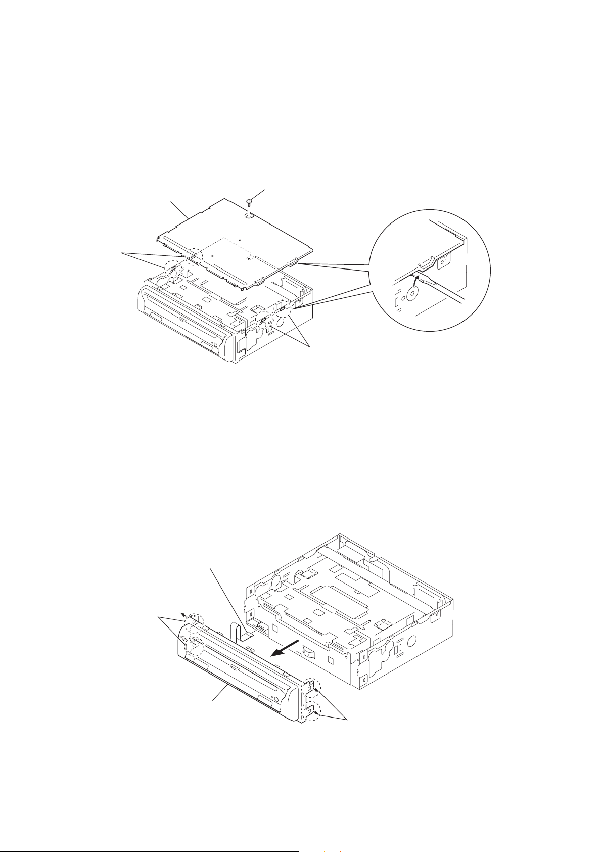
Note: Follow the disassembly procedure in the numerical order given.
3-2. COVER
4
cover
3
two claws
1
screw
(PTT2.6 × 6)
3-3. FRONT PANEL ASSY
2
two claws
4
wire (flat type) (FFC) (6 core)
(CN202)
2
two claws
12
5
front panel assy
3
1
two claws

3-4. MECHANISM DECK
(SA-MDAM01)
9
mechanism deck (SA-MDAM01)
3
screw (PTT2.6 × 4)
4
7
two screws
(PTT2.6
5
vibration proof (D) paper
×
4)
8
bracket (CD)
DVX-11A
1
two screws
(PTT2.6
3-5. DSP BOARD, MAIN BOARD
1
three ground point screws
2
three ground point screws
2
screw (PTT2.6 × 4)
6
flexible flat cable (50P)
×
4)
(CN500)
screw (PTT2.6 × 4)
3
7
main board
6
DSP board
5
4
two screws
(PTT2.6
×
4)
13

DVX-11A
3-6. BRACKET L/R
mechanism deck block
qs
L cover
0
main damper
coil spring
9
damper
8
screw (SV01)
qa
4
main damper
coil spring
screw
(SU01)
7
R cover
6
screw (SU01)
qg
rear damper coil spring
qf
rear damper
qd
screw (SU01)
5
flexible board
(CS104)
3
damper
1
3-7. CHASSIS (DVD) BLOCK
2
Release the spring from the chassis
and hook it on the portion
1
Release the spring from the chassis
and hook it on the portion
a
screw (SV01)
.
portion
chassis
a
2
FPC sensor cover
b
.
b
portion
Note: After the screws are installed,
apply the screw-locking compound.
14
3
Slide the lever in the direction
of arrow.
4
chassis (DVD) block

3-8. SERVO BOARD
qa
servo board
7
4
3
claw
flexible board
(CS101)
claw
6
FPC cover
9
5
claw
2
two screws
(2
DVX-11A
0
connector
(CS103)
×
3)
3-9. GEAR COVER
8
claw
1
screw (2 × 3)
1
2
gear cover
flexible board
(CS102)
15

DVX-11A
3-10. FEED MOTOR (LOADING) (M1)
4
feed motor (loading) (M1)
2
screw (SU02)
1
screw (SA02)
3
motor bracket F
3-11. CHASSIS CLAMP
clamp coil spring
1
hook
2
clamp coil
spring
Note: After the screws are installed,
apply the screw-locking compound.
3
chassis clamp
16

SECTION 4
ELECTRICAL ADJUSTMENTS
DVX-11A
3-12. BRACKET ROLLER
4
L roller torsion spring
5
bracket roller
2
boss
1
Remove the lever in the direction
of arrow A.
A
3
R roller torsion spring
TEST MODE
This set have the test mode function.
<Set the Test Mode>
1. Connect a monitor and turn on the regulated power supply.
(Not insert a disc)
2. Push the preset [4] button.
3. Push the preset [5] button.
4. Press the preset [1] button for more than two seconds.
5. When the test mode is set, the screen of “D VD PLAYER TEST
MODE” will be displayed and display the version of following items.
Display Item
FILE NAME Update file name
FIRMWARE VER AV decoder version
CORE VER AV decoder core software version
FLASH ID Flash memory ID
SYSTEM VER System microcomputer version
ATAPIDRV FW VER DVD driver version
REGION Region number
TV OUTPUT Video color sytem format
MACROVISION VER Macro vision version
<Release the Test mode>
1. Push the [OFF] button.
1717
 Loading...