

Page 1

Digital Wireless
5-014-891-01 (1)
Transmitter
Operating Instructions
DWT-B30
© 2019 Sony Corporation
Page 2

Table of Contents
Features ...................................................................... 3
Parts Identification ................................................... 4
Power Supply ............................................................. 5
Installing the batteries ............................................ 5
Setting the Transmission Channel ........................... 6
Selecting the group/channel ................................... 6
Using Cross Remote .................................................. 7
Pairing with a receiver ........................................... 7
Using the Encrypted Transmission Function ......... 8
Using the encryption key modes (SECURE KEY /
AES256) .............................................................. 8
Using the password mode (PASSWORD) ............ 9
Basic Menu Operations ............................................ 9
Setting Menus .......................................................... 10
Unit name setting (NAME) ................................. 10
Selecting the frequency band (BAND) ................ 10
Selecting the group/channel (GP/CH) ................. 10
Audio attenuator setting (AF ATT) ..................... 10
Low-cut filter setting (LCF) ................................ 10
Lock function (LOCK) ........................................ 11
Power save setting (POWER SAVE) .................. 11
Setting the battery type (BATTERY TYPE) ....... 11
Cross Remote (RF REMOTE) ............................. 11
Receiver search function (SEARCH RX) ............ 11
Audio codec mode setting (CODEC MODE) ..... 12
Encrypted transmission function Setting
(ENCRYPTION) ............................................... 12
Audio input level setting (INPUT LEVEL) ......... 12
Audio phase switch function (AF PHASE) ......... 12
Generating an internal signal (INTERNAL
SG) ..................................................................... 12
Setting the RF output power (RF POWER) ........ 12
Setting the maximum RF output power (MAX RF
POWER) ............................................................ 13
Displaying the accumulated use time (TIME) ..... 13
Setting the brightness of the display
(BRIGHTNESS) ................................................ 13
Automatic dimming of the display (DIMMER
MODE) .............................................................. 13
Settings storage function (USER MEMORY) ..... 13
Power source priority setting (POWER
PRIORITY) ........................................................ 14
Resetting parameters to their factory settings
(FACTORY PRESET) ...................................... 14
Displaying the software version (VERSION) ..... 14
Attaching With the Soft Case ................................. 14
Changing the direction of the belt clip ................ 14
Wrapping the microphone cable around the soft
case .................................................................... 14
Removing the unit from a belt ............................. 15
Block Diagram ......................................................... 16
Troubleshooting ....................................................... 17
Important Notes on Operation .............................. 18
Notes on using the transmitter ............................. 18
On cleaning .......................................................... 18
Notes on simultaneous multi-channel
operation ............................................................ 18
Note on microphone and transmitter
combinations ...................................................... 18
CROSS REMOTE Compatibility ........................ 18
Specifications ........................................................... 19
Carrier Frequencies and Channel Steps ............... 21
2
Page 3

Features
Encrypted transmissions
AES 256-bit encryption allows for highly secure wireless
transmissions.
The DWT-B30 is a digital wireless transmitter for a UHF
synthesized wireless microphone system to be used for
broadcast or movie production purpose. This transmitter is
suitable for Electronic News Gathering (ENG) and
Electronic Field Production (EFP).
What is DWX?
DWX refers to Sony’s new digital wireless microphone
system. The DWX series reflects Sony’s extensive
expertise in professional microphones and sound design. It
represents a successful blend of Sony know-how, wireless
technology renowned for stability, and cutting-edge digital
audio technology.
In addition to realizing the high sound quality possible
with a digital system, the DWX series supports multichannel simultaneous operation, encrypted transmission,
and metadata transmission for monitoring the status of
multiple transmitters. Using a main link and a separate
additional link, remote control of transmitters from the
receiver is also possible. With its many advanced features,
the system has the potential to revolutionize the workflow
of professional applications.
What is WiDIF-HP?
WiDIF-HP (WiDIF: Wireless Digital Interface Format,
HP: High Profile) is a wireless digital audio interface
format developed by Sony.
It enables highly secure transmission with high sound
quality and low system latency, and supports simultaneous
multi-channel operation.
What is Cross Remote?
Cross Remote is a system that allows transmitters to be
monitored and controlled from a receiver and the Wireless
Studio control software installed on a computer connected
to the receiver.
For example, the settings of a transmitter worn under
clothing can be easily changed over the wireless link.
Simultaneous multi-channel operation
Simultaneous multi-channel operation is made possible
with the 375-kHz interval channel plan.
High sound quality and low latency
Low system latency of 1.2 ms is achieved when using
CODEC MODE2.
Switch between four audio codec modes based on your
operational needs.
Switchable mic or line input level and
adjustable attenuator
Supports line/mic input and is equipped with an audio
attenuator that is adjustable in 3 dB steps up to a maximum
of 48 dB during mic input. The attenuator can be
controlled remotely from the receiver.
RF transmission output switching
available
RF transmission output can be set to 2, 10, or 25 mW
according to multi channel operation or long-distance
transmission priority.
For details, see “Setting the RF output power (RF
POWER)” (page 12).
User-set memory function
Various settings can be saved and activated on the
transmitter.
For further details, see “Settings storage function (USER
MEMORY)” (page 13).
USB for external power supply
An external supply enables operation for long periods of
time and power supply in emergencies.
Compact, lightweight, and rugged design
The unit is equipped with a magnesium-alloy casing,
providing a body that is durable in addition to being
compact and lightweight.
Supports operation for long periods of
time and various battery types
The DWT-B30 supports various battery types, such as AA
alkaline batteries, lithium ion batteries, and NiMH
batteries. It can be operated for approximately 6.5 hours
when powered by alkaline batteries.
Organic EL (electroluminescent) display
The quick response of the OLED (organic light-emitting
diode) display enables real-time operating conditions to be
displayed clearly and accurately.
For details, see “Audio codec mode setting (CODEC
MODE)” (page 12).
3
Page 4

Parts Identification
a Antenna
b AF (audio input level) /PEAK indicator
Lights up green when the signal input is stronger than the
reference level.
Lights up red when the signal input is 3 dB below the level
at which distortion begins.
European model
Connector front view
1: GND
2: +5.2 V DC output (for power supply of lavalier
microphone)
3: HOT (input impedance 4.7 kohms or more with
+5.2 V DC)
Connecting the microphone
Microphone (optional)
To secure the connection, turn the ring on the
connection plug to lock it.
e + or – button
Selects functions or values shown on the display.
Holding down the – button while switching on the
transmitter activates the pairing operation for the wireless
remote control function.
f POWER switch
Turns the transmitter ON or OFF.
c POWER indicator
Lights up green when the transmitter is turned on. When
the battery is exhausted, the indicator starts flashing.
d Audio input connector
Connects the output plug from the optional lavalier
microphone.
This connector also accepts the input from another wired
microphone connected through the supplied microphone
cable, or the audio output from a mixer, etc.
US model
Connector front view
1: DC output + 5.2 V (for lavalier microphone
power supply)
2: HOT (input impedance 4.7 kohms or more)
3: COLD (input impedance 4.7 kohms or more)
4: GND
To connect a microphone
Microphone (optional)
g Battery compartment
Accommodates two LR6 (size AA) alkaline batteries.
For details on how to insert the batteries, see “Power
Supply” (page 5).
h SET button
Adjusts displayed function settings and enters the value.
Holding down the SET button while switching on the
power turns the transmitter on without sending a signal.
i USB connector (Micro USB)
The transmitter can be operated for long periods of time
using a mobile battery or commercial USB power source.
j Display section
A RF transmission indication
Indicates the current transmission status.
: Currently transmitting
—:Transmission stopped
To secure the microphone cable
connection, be sure to turn and lock
the connector cover.
4
Page 5

B RF (radio frequency) transmission power
indication
Indicates the current transmission power setting. You can
change the setting with the RF transmission power setting
function.
H: transmitting at 25 mW
M: transmitting at 10 mW
L: transmitting at 2 mW
C Audio input level meter
Indicates the input signal level.
Power Supply
The transmitter can operate on two LR6 (size AA) alkaline
batteries continuously for about 6.5 hours at 25 °C (77 °F).
Connecting a mobile battery to the USB connector enables
operation for a long period of time.
Installing the batteries
D Reference level gauge
Indicates the reference input level. When the attenuation is
0 dB with INPUT LEVEL set to MIC, –58 dBu (–60 dBV)
is indicated. When LINE is selected for INPUT LEVEL,
+4 dBu is indicated.
E Peak indicator
Warns of excessive input by lighting up when the signal is
3 dB below the level at which distortion begins.
F Lock indicator
Indicates whether the accidental operation locks are
enabled. Nothing is displayed when the lock function is
disabled.
: Operation of the POWER button is locked.
: Changes to the settings are locked.
: Operation of the POWER button and changes to the
settings are locked.
For details, see “Lock function (LOCK)” (page 11).
G Cross Remote condition indication
Indicates the signal transmission condition of the wireless
remote control function (4 levels).
: Good transmission
: Somewhat good transmission
: Somewhat poor transmission
: Poor transmission
: Unable to communicate with paired receiver
When the wireless remote control function is off, this
indication does not appear.
H Power display
Displays the type of power source being used.
: Operating on battery power, displays remaining
battery level.
: Operating on USB power.
For details, see “Battery indication” (page 5).
I Menu display section
The status of 17 different functions are displayed here. To
select the function, press the + or – button repeatedly.
For details, see “Setting Menus” (page 10).
1
Squeeze the battery-holder tabs inward (in the
direction of the arrows) and slide out the battery
holder.
2
Insert new batteries, making sure the polarities are
correct, and then return the battery holder to its
original position.
Battery indication
The power status is indicated by eight level indications.
Replace both batteries when the battery indication starts to
flash.
Be sure to check the expiration date printed date on the
new batteries before using them.
Notes
• When BATTERY TYPE is set to TYPE1, the power
status is indicated based on the use of new LR6 (size
AA) Sony Alkaline batteries. An incorrect indication
may result when a different kind of batteries, a different
brand of batteries or old batteries are used. If you plan to
use other kind of batteries than alkaline, set the
BATTERY TYPE function according to the type of
batteries to be used.
• If you plan to use the transmitter for a long period of
time, it is recommended that you replace the batteries
with brand new ones.
• Use USB power source capable of supplying 1.0 A or
higher.
5
Page 6

• Operation is not guaranteed on all USB power sources.
Make sure to test the power source before using it.
• The transmitter cannot be used when connected to a USB
device that possesses communication functions, such as
a computer.
Setting the Transmission Channel
For details on BATTERY TYPE setting, see “Setting the
battery type (BATTERY TYPE)” (page 11).
The transmitter provides groups of interference-free
channels. When using multiple microphones and
transmitters at the same time (simultaneous multi-channel
operations) within the same area, selecting the same group
and using a channel within that group can prevent signal
interference.
To set the transmission channel on the transmitter, first you
select the group and channel using the RF indicator and
scanning functions on the receiver. Next you set the group
and channel parameters to match the setting on the
receiver.
Notes
• Certain transmission channels cannot be used with the
wireless remote control function.
For details on transmission channels that support the
wireless remote control function, refer to “Sony Digital
Wireless Microphone System Frequency Lists” on the
supplied CD-ROM.
• When selecting the channel, “(INCOMPATIBLE WITH
RF REMOTE)” will slide across the display for
transmission channels that cannot be used with the
wireless remote control function.
• When a transmission channel that cannot be used with
the wireless remote control function is selected,
“RESTRICTED BY GP/CH SETTING” appears on the
RF REMOTE screen and the wireless remote control
function cannot be used. To enable use of the wireless
remote control function, select transmission channels for
which “(INCOMPATIBLE WITH RF REMOTE)” does
not appear during channel selection.
Selecting the group/channel
Notes
• Before doing this procedure, use the BAND function
(see page 10) to set the transmitter to the bandwidth of
the receiver you are using.
• The setting for this function cannot be changed during
actual signal transmission.
Set the transmitter group (GP) and channel (CH) as
follows:
For details on groups and channels, refer to “Sony Digital
Wireless Microphone System Frequency Lists” on the
supplied CD-ROM.
For details on menu operation, see “Basic Menu
Operations” (page 9).
1
Turn off the power, and then while holding down the
SET button, turn the power on.
The signal transmission stops.
6
Page 7

2
Press the + or – button repeatedly until the GP/CH
indication is displayed.
3
Hold down the SET button until the item to be set
flashes.
4
Press the + or – button repeatedly to select a group.
5
Press the SET button to enter the group.
The channel indication starts flashing.
6
Press the + or – button repeatedly to select a channel.
7
Press the SET button to enter the channel.
Note
To start signal transmission with the selected channel, turn
off the power and then turn it on again.
To set the group/channel using the pairing
mode of the Cross Remote
When the transmitter is paired with the receiver, the
transmission channel of the transmitter is set to the
receiving channel on the receiver automatically.
For details, see“Pairing with a receiver” (page 7).
Using Cross Remote
This transmitter is equipped with a wireless remote control
function that can be used to set the parameters (low-cut
filter, attenuation operation, power save mode, etc.) of the
transmitter through the receiver or other devices. This
function makes it easier to operate and manage the
microphone system while in the field.
This wireless control is 2.4 GHz IEEE802.15.4 compliant
and has no effect on the RF band of digital wireless audio.
This function is activated when pairing is established
between the transmitter and the receiver using the RF
REMOTE function.
Pairing must be done first before the wireless remote
control function can be used.
Note
If “RESTRICTED BY GP/CH SETTING” appears on the
RF REMOTE screen, the wireless remote control function
cannot be used. To use the wireless remote control
function, select a different transmission channel.
For details on how to change the transmission channel, see
“Setting the Transmission Channel” (page 6).
Pairing with a receiver
Pairing links the transmitter with the receiver which the
wireless remote control function is to be used.
When the transmitter has been paired with a receiver
through the receiver operation, turning on the transmitter
while holding down the – button establishes the pairing
immediately.
To carry out pairing through menu operations on the
transmitter, do the following.
1
Set the receiver to be used for controlling the
transmitter to pairing mode.
For details, refer to the operating instructions
supplied with the receiver.
2
Press the + or – button repeatedly until the RF
REMOTE indication is displayed.
3
Hold down the SET button until the item to be set
flashes.
4
Press the + or – button repeatedly to select PAIRING.
5
Press the SET button to enter.
The transmitter sends a pairing request to the receiver
which is on pairing mode.
Before established pairing, if you press any operation
key on the transmitter, pairing mode will be cancelled.
When pairing has been established, the wireless
remote control condition level (indicated by )
7
Page 8

goes up, RF REMOTE turns on, and the remote
control function becomes operative.
Using the Encrypted
To use the Cross Remote with a previous
pairing
In the RF REMOTE indication, select ON.
Notes
• When you set RF REMOTE to ON, the transmitter will
communicate with the receiver to which it was
previously paired. To use the wireless remote control
function with another receiver, you must perform the
pairing procedure for that receiver.
• Multiple transmitters cannot be paired with the same
receiver.
• If you reset all parameters by using the FACTORY
PRESET function (see page 14), the pairing setting of
the transmitter is also cleared.
The following transmitter settings can be done
from the remote control:
• Transmitter name setting
• Frequency band/group/channel selection
• RF transmission power setting
• MIC/LINE setting and attenuator setting for audio input
level
• Low-cut filter setting
• Power save setting
• Resetting accumulated use time
• Audio codec mode setting
• Internal signal setting
• POWER switch lock setting
For details on menu operation, see “Setting Menus”
(page 10).
To perform remote control, the receiver must be equipped
with a control function for the setting you want to control.
For details, refer to the operating instructions supplied
with the receiver.
To cancel the Cross Remote
In the RF REMOTE indication, select OFF.
Transmission Function
The unit is capable of transmitting encrypted signals to
prevent unwanted surveillance.
To use the function, select one of the following encryption
modes.
Encryption key modes (SECURE KEY / AES256):
An encryption key is automatically generated by the
transmitter and used by both the transmitter and receiver in
these one-to-one encrypted transmission modes.
The SECURE KEY mode is compatible with first and
second generation DWX-series devices.
The AES256 mode uses AES 256-bit encryption for a
higher level of security in transmissions.
Password mode (PASSWORD): A user-created
password of up to 8 characters can be set for multiple
transmitters (this unit) and receivers in this mode. This
allows encrypted transmission within a group.
Note
Make sure that encryption mode settings are identical on
both the transmitter (this unit) and the receiver.
Using the encryption key modes
(SECURE KEY / AES256)
Use these modes for one-to-one encrypted transmission
between one transmitter (this unit) and one receiver.
To enable encrypted transmission in these modes, an
encryption key that cannot be read from the outside is
automatically generated by the unit, and the key is
transmitted to the receiver via the wireless remote control
function.
A new encryption key for the transmitter (this unit) and
receiver is automatically generated for each key
transmission, resulting in highly secure communication.
The encryption key for the transmitter (this unit) and
receiver is retained when the unit is turned off, allowing
you to resume the same encrypted transmission the next
time you turn the unit on.
Notes on the Cross Remote
The wireless remote control function on the transmitter
uses the 2.4-GHz band and may thus be subject to
interference from other devices.
• When pairing fails (“Pairing fail” is displayed),
successful communication between the transmitter and
the receiver has not occurred within a given amount of
time. Pairing may be harder to do when another receiver
is engaged in pairing nearby.
• When it becomes hard to use the remote control, the
remote control may be improved by switching the
wireless remote control function off, then on again in the
RF REMOTE display, then re-pairing with the
transmitter (change to a channel with less interference).
1
Prepare the transmitter (this unit).
1 Hold down the SET button in the unit’s
ENCRYPTION screen until the setting value
blinks.
2 Use the + and – buttons to select SECURE KEY or
AES256, and press the SET button.
2
Prepare the receiver.
Set the receiver that will receive the encryption key to
SECURE KEY or AES256.
For details on receiver operations, refer to the
receiver’s operating instructions.
8
Page 9
3
Exchange the encryption key.
On the receiver side, select REMOTE (wireless
remote) as the encryption key exchange method, and
perform encryption key exchange.
REMOTE cannot be selected when the wireless
remote control function is disabled.
Note
If the receiver does not support AES256 mode, select
SECURE KEY.
For details, refer to the receiver’s operating
instructions.
The unit searches for the receiver with which it is
paired.
When the receiver is found, the encryption key is
exchanged, and encrypted transmission begins.
Using the password mode
(PASSWORD)
Use this mode for encrypted transmissions between
multiple paired transmitters (this unit) and receivers.
When the same user-created password is set on both the
transmitters (this unit) and the receivers, the audio signal
can be decoded. This mode is useful when you want to
operate multiple transmitters (this unit) and receivers as a
group, or receive transmissions from a single transmitter
(this unit) on multiple receivers at the same time.
1
Hold down the SET button in the unit’s
ENCRYPTION screen until the setting value blinks.
2
Use the + and – buttons to select PASSWORD, and
press the SET button.
3
Enter a password of up to 8 characters on the unit.
For details on how to enter the password, see the
procedure described in “Unit name setting (NAME)”
(page 10).
4
Set the encrypted transmission setting on the receiver
to PASSWORD.
5
Set the same password that you set for the unit on the
receiver.
For details on receiver operations, refer to the
receiver’s operating instructions.
Note
We recommend changing the password periodically.
Basic Menu Operations
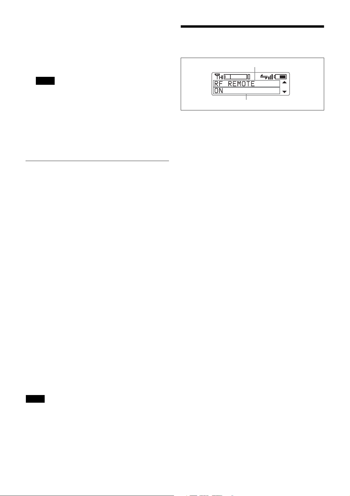
Function name
Item to be set
1
Press the + or – button repeatedly until the function to
be set appears.
Holding down the + and – buttons allows you to cycle
through screens quickly.
In addition, holding down the + button while the first
setting item of the menu is displayed allows you to
jump to the last setting item, while holding down the
– button while the last setting item of the menu is
displayed allows you to jump to the first setting item.
2
Hold down the SET button until the item to be set
flashes.
3
Press the + or – button to change the setting.
4
Press the SET button to enter the setting.
Setting items in the menu
• NAME (transmitter name) setting
• BAND (frequency band) selection
• GP/CH (group/channel) selection
• AF ATT (audio attenuator level) setting
• LCF (low-cut filter) setting
• LOCK function
• POWER SAVE setting
• BATTERY TYPE (battery type) setting
• RF REMOTE (wireless remote control) function
• SEARCH RX (receiver search) function
• CODEC MODE (audio codec mode) setting
• ENCRYPTION (encrypted transmission function)
setting
• INPUT LEVEL (audio input level) setting
• AF PHASE (audio phase switch) setting
• INTERNAL SG (internal signal generator) function
• RF POWER (RF transmission power) setting
• MAX RF POWER (maximum RF transmission power)
setting
• TIME (accumulated use time) indication
• BRIGHTNESS (display brightness) setting
• DIMMER MODE (automatic display dimmer) setting
• USER MEMORY (settings storage) function
• POWER PRIORITY (power source priority) setting
• FACTORY PRESET (factory settings) function
• VERSION (software version) display
9
Page 10
Setting Menus
selected frequency band/group/channel, turn off the
power and then turn it on again.
The functions and parameters of the settings menu are
explained here. Underlined items are the factory setting.
Unit name setting (NAME)
You can specify a transmitter name of up to 16 characters.
The factory setting for the transmitter name is the model
name and serial number. The transmitter name is sent to
the receiver as metadata and is used by the receiver to
distinguish between different transmitters.
+: The first press on the + button displays the character set.
You can then use the + and – buttons to select the desired
character. And then, pressing the SET button adds the
selected character to the end of the current name.
– : Deletes the last character in the current name.
SET: Enters the character or edited name.
Note
You cannot insert or delete a character in the middle of the
name.
Using wireless remote control, this function can be
controlled from the receiver and other devices.
For details on wireless remote control function, see
“Using Cross Remote” (page 7).
Selecting the frequency band (BAND)
Match the frequency range on this transmitter to that of the
Sony digital wireless receiver.
See “Carrier Frequencies and Channel Steps” (page 21)
for differences in frequency ranges that can be set for
optional receivers combined with this transmitter.
For details about the frequency range of each band, refer
to “Sony Digital Wireless Microphone System Frequency
Lists” on the supplied CD-ROM.
Using wireless remote control, this function can be
controlled from the receiver and other devices.
Selecting the group/channel (GP/CH)
See “Carrier Frequencies and Channel Steps” (page 21)
for factory settings.
For details, see “Selecting the group/channel” (page 6).
Using wireless remote control, this function can be
controlled from the receiver and other devices.
For details on wireless remote control function, see
“Using Cross Remote” (page 7).
Audio attenuator setting (AF ATT)
When INPUT LEVEL is set to MIC, select the attenuator
level for audio inputs.
Note
This setting cannot be changed when INPUT LEVEL is set
to LINE.
Input audio from the connected microphone, and use the +
and – buttons to select the attenuator level while viewing
the input level meter.
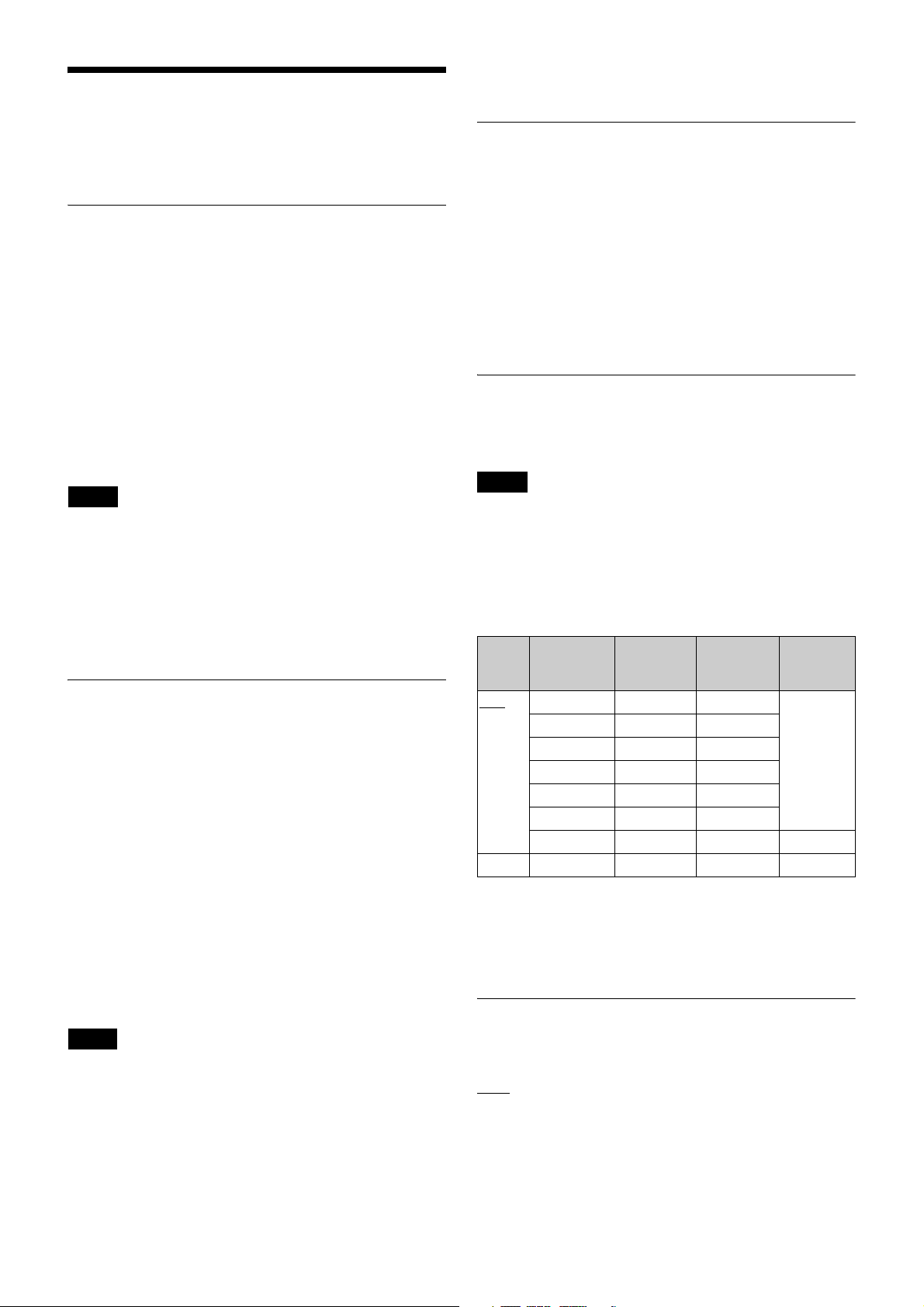
The reference levels for the various settings are as follows.
Input Attenuation
(dB)
MIC 0 –58 –22 36
3 –55 –19
6 –52 –16
9 –49 –13
3 dB steps 3 dB steps 3 dB steps
45 –13 +23
48 –10 +24 34
LINE – +4 +24 20
The audio attenuator setting can be changed from the
receiver and other devices via the wireless remote control
function.
Reference
input level
(dBu)
Maximum
input level
(dBu)
Headroom
(dB)
For details on wireless remote control function, see
“Using Cross Remote” (page 7).
Notes
• The setting for this function cannot be changed during
actual signal transmission. To change the setting, turn
off the transmitter first. Then, while holding down the
SET button, turn the power on. Then change the setting
after the signal transmission has stopped.
• Be sure to select the group/channel right after selecting
the frequency band. To start signal transmission with the
For details, see “Using Cross Remote” (page 7).
Low-cut filter setting (LCF)
The frequency of the low-cut filter can be set.
: Turns off the low-cut filter.
OFF
20 30 40 50 60 70 80 90 100
120 140 160 180 200 220 (Hz): Low-cut filter is set
according to the selected frequency.
Using wireless remote control, this function can be
controlled from the receiver and other devices.
10
Page 11

For details on wireless remote control function, see
“Using Cross Remote” (page 7).
You can also use the wireless remote control to change the
receiver back to normal operation.
Lock function (LOCK)
Lock and prevent operations such as those for the POWER
button and for settings changes. This prevents you from
accidentally turning the unit off, for example.
UNLOCK
button and settings changes.
POWER: Locks POWER button operations only.
SETTING: Locks setting change operations only.
POWER+SETTING: Locks both POWER button and
settings change operations.
Disabling the lock function
Set LOCK to UNLOCK.
Changes to the LOCK function are enabled, even when
settings change operations are locked.
Lock function shortcuts
You can use to the unit’s buttons to enable or disable the
POWER+SETTING setting and all lock functions without
displaying the settings menu.
To enable the POWER+SETTING setting, hold down the
SET and + buttons at the same time until the
POWER+SETTING icon appears.
To disable the lock, hold down the SET and – buttons at the
same time until the lock indicator disappears.
The lock setting can be changed from the receiver and
other devices via the wireless remote control function.
For details, see “Using Cross Remote” (page 7).
Note
Changes to settings via the wireless remote control
function are enabled, even when settings change
operations are locked. However, changes to settings will
not be possible via the wireless remote control function on
receivers that do not support the settings change lock
function.
: Disables operation locks for the POWER
For details on wireless remote control function, see
“Using Cross Remote” (page 7).
Setting the battery type (BATTERY
TYPE)
Set this item according to the type of batteries you use to
obtain accurate battery power status indication.
TYPE1
characteristics of new LR6 (size AA) Sony Alkaline
batteries. Select this for LR6 (size AA) alkaline batteries.
TYPE2: Select this for rechargeable nickel-metal-hydride
batteries with capacities of about 2000 mAh.
TYPE3: Select this for lithium batteries.
TYPE4: Select this for rechargeable nickel-metal-hydride
batteries with capacities of about 2500 mAh.
The characteristics of batteries change according to battery
type and environmental conditions. It is recommended that
you learn the characteristics of batteries you use before
using them.
: The power status is indicated based on
Note
Cross Remote (RF REMOTE)
Enable use of the wireless remote control function between
the unit and the receiver that will be used with the unit.
OFF
: Disables the wireless remote control function.
ON: Enables use of the wireless remote control function
with the paired device.
PAIRING: Executes a new pairing.
For details, see “Pairing with a receiver” (page 7).
Receiver search function (SEARCH RX)
Use this function to quickly locate a receiver
communicating on the same frequency as the unit.
When the receiver is found, the receiver will react (e.g., the
receiver’s display will blink).
For details, refer to the receiver’s operating instructions.
Power save setting (POWER SAVE)
To conserve power, this setting allows you to put all
transmitter functions to sleep.
ACTIVE
SLEEP: The sleep function is on. During sleep, the
POWER indicator flashes at 2-second intervals.
To change back to normal operation
During sleep, press the SET, +, or – button.
: The transmitter operates normally.
Note
If a receiver does not support the receiver search function,
it will not react.
For details on receiver actions, refer to the receiver’s
operating instructions.
Searching for receivers
Hold down the SET button in the SEARCH RX screen,
and press the SET button again while the “SEARCH?
YES” display is blinking.
You can hold down both the + button and – button for 1
second or more at the same time to start the receiver search
function.
11
Page 12

Audio codec mode setting (CODEC
MODE)
MODE1: Audio codec mode that is compatible with first
generation DWX-series devices.
MODE2
times while maintaining transmission stability and high
audio quality.
MODE3: Audio codec mode that uses additional signal
processing to suppress noise caused by unexpected pulse
interference.
MODE4: Audio codec mode that prioritizes audio quality
for faithful reproduction while maintaining transmission
stability and low delay time.
Under normal circumstances, we recommend using
MODE2 (prioritizing delay times) or MODE4 (prioritizing
audio quality).
However, use MODE1 when when using the unit in
conjunction with first generation DWX-series devices, and
use MODE3 in environments where unexpected pulse
interference may occur.
The audio delay durations that occur when transmitting
and receiving with each mode will vary depending on the
receiver’s operating environment. For details, refer to the
receiver’s operating instructions.
: Audio codec mode that prioritizes short delay
For details, see “Using Cross Remote” (page 7).
Audio phase switch function (AF
PHASE)
Switch the phase when a microphone that outputs with
inverted phase is connected.
NORMAL
INVERT: Enables internal phase inversion on the unit.
: Disables phase inversion.
Generating an internal signal
(INTERNAL SG)
This transmitter generates a 1-kHz reference level sine
wave that can be used to adjust or check the audio level of
the receiver or the system that you are using. This internal
signal is outside the control of the attenuator.
1 kHz: A 1-kHz internal signal is generated.
OFF
: An internal signal is not generated.
Note
If the transmitter is turned off while the reference signal
function is on, the function will turn off automatically.
Using wireless remote control, this function can be
controlled from the receiver and other devices.
The audio codec mode setting can be changed from the
receiver and other devices via the wireless remote control
function.
For details, see “Using Cross Remote” (page 7).
Encrypted transmission function
Setting
Enable the encrypted transmission function.
SECURE KEY: Enables the encryption key mode that is
compatible with first and second generation DWX-series
devices.
AES256: Enables the AES256 encryption key mode.
PASSWORD: Enables the password mode.
OFF
: Disables the encrypted transmission function.
For details, see “Using the Encrypted Transmission
Function” (page 8).
(ENCRYPTION)
Audio input level setting (INPUT LEVEL)
Set the input level to the analog head amp.
Select LINE or MIC according to the audio source
connected to the audio input connector.
The factory setting is MIC.
The MIC/LINE setting for the audio input level can be
changed from the receiver and other devices via the
wireless remote control function.
For details on wireless remote control function, see
“Using Cross Remote” (page 7).
Setting the RF output power (RF
POWER)
You can set the RF output power.
2 mW (LOW): transmitted by 2 mW
10 mW (MID)
25 mW (HIGH): transmitted by 25 mW
Notes
• The setting for this function cannot be changed during
actual signal transmission. To change the setting, turn
off the transmitter first. Then, while holding down the
SET button, turn the power on. And then, change the
setting after the signal transmission has stopped.
• To start signal transmission with the selected RF output
power setting, turn off the power and then turn it on
again.
Using wireless remote control, this function can be
controlled from the receiver and other devices.
For details on wireless remote control function, see
“Using Cross Remote” (page 7).
The maximum RF output power can be configured on the
unit.
: transmitted by 10 mW
12
Page 13

For details, see “Setting the maximum RF output power
(MAX RF POWER)” (page 13).
Automatic dimming of the display
(DIMMER MODE)
Setting the maximum RF output
power
You can set the maximum RF output power of the unit.
2mW MAX: Sets the maximum to 2 mW.
10mW MAX: Sets the maximum to 10 mW.
25mW MAX
Notes
• The setting for this function cannot be changed during
actual signal transmission. To change the setting, turn
off the transmitter first. Then, while holding down the
SET button, turn the power on. And then, change the
setting after the signal transmission has stopped.
• To start signal transmission with the selected RF output
power setting, turn off the power and then turn it on
again.
• Always perform pairing after changing the maximum
RF output power setting for a transmitter. If you fail to
do so, configuration of RF output power settings via the
wireless remote control function may become
impossible.
For details on pairing, see “Using Cross Remote”
(page 7).
(MAX RF POWER)
: Sets the maximum to 25 mW.
Displaying the accumulated use time
(TIME)
You can display the accumulated battery use time as a
rough estimate of total transmitter usage.
The factory setting is “00:00”.
To reset the accumulated time indication
1
Hold down the SET button until the time indication
flashes.
2
Press the – button so “00:00 RESET” appears, and
then press the SET button.
Using wireless remote control, this function can be
controlled from the receiver and other devices.
For details on wireless remote control function, see
“Using Cross Remote” (page 7).
Setting the brightness of the display
(BRIGHTNESS)
Ten levels of brightness can be selected for the organic
light-emitting diode display.
The selectable settings are the following:
(Dark) 1 2 3 4 5 6 7
8 9 10 (Bright)
The organic light-emitting diode display can be set to dim
or turn off after a certain amount of time.
AUTO OFF
display goes on again when you press the SET, +, or –
button.
AUTO DIMMER: The display dims after 30 seconds. The
display becomes bright again when you press the SET, +,
or – button.
ALWAYS ON: The display stays on at the brightness
level set with the BRIGHTNESS function.
: The display turns off after 30 seconds. The
Settings storage function (USER
MEMORY)
Store setting values on the unit, or load previously saved
setting values.
When you execute SAVE, the values for the following
settings will be saved.
• NAME (transmitter name) setting
• BAND (frequency band) selection
• GP/CH (group/channel) selection
• AF ATT (audio attenuator level) setting
• LCF (low-cut filter) setting
• LOCK function
• RF REMOTE (wireless remote control) function
• CODEC MODE (audio codec mode) setting
• ENCRYPTION (encrypted transmission function)
setting
• INPUT LEVEL (audio input level) setting
• AF PHASE (audio phase switch) setting
• RF POWER (RF transmission power) setting
• MAX RF POWER (maximum RF transmission power)
setting
• BRIGHTNESS (display brightness) setting
• DIMMER MODE (automatic display dimmer) setting
• POWER PRIORITY (power source priority) setting
When you execute LOAD, the saved setting values will be
loaded.
Notes
• This function cannot be executed during actual signal
transmission. Turn the unit off, and then hold down the
POWER button while pressing the SET button to turn
the unit on in a state where signals are not transmitted
before execution.
• To start signal transmission after using this function,
turn off the unit and then turn it on again.
• You cannot execute LOAD if you have never executed
SAVE.
• If you execute LOAD while performing the following
operations after setting values were stored, proper
communication with the receiver will not be possible. In
such cases, perform pairing or encrypted transmission
settings again.
13
Page 14
- Pairing the unit or establishing encrypted transmission
with a different receiver.
- Pairing the receiver that was paired with the unit with
a different transmitter.
- Establishing encrypted transmission between the
receiver and a different transmitter.
Power source priority setting (POWER
PRIORITY)
This device can be configured to use a priority power
source when batteries are installed and when connected to
a USB power source at the same time.
When the priority power source has been exhausted, it
automatically switches to the other power source.
BATTERY
power source.
EXTERNAL: Operates using USB as the primary power
source.
Note
The transmitter may temporarily be turned off and
restarted when switching power sources depending on the
battery type and status and the USB power source.
: Operates using the batteries as the priority
Attaching With the Soft Case
The transmitter can be attached to the user with the
supplied soft case.
Changing the direction of the belt
clip
The belt clip attached to the rear of the soft case can be
rotated 0, 90, 180, or 270 degrees in relation to the unit.
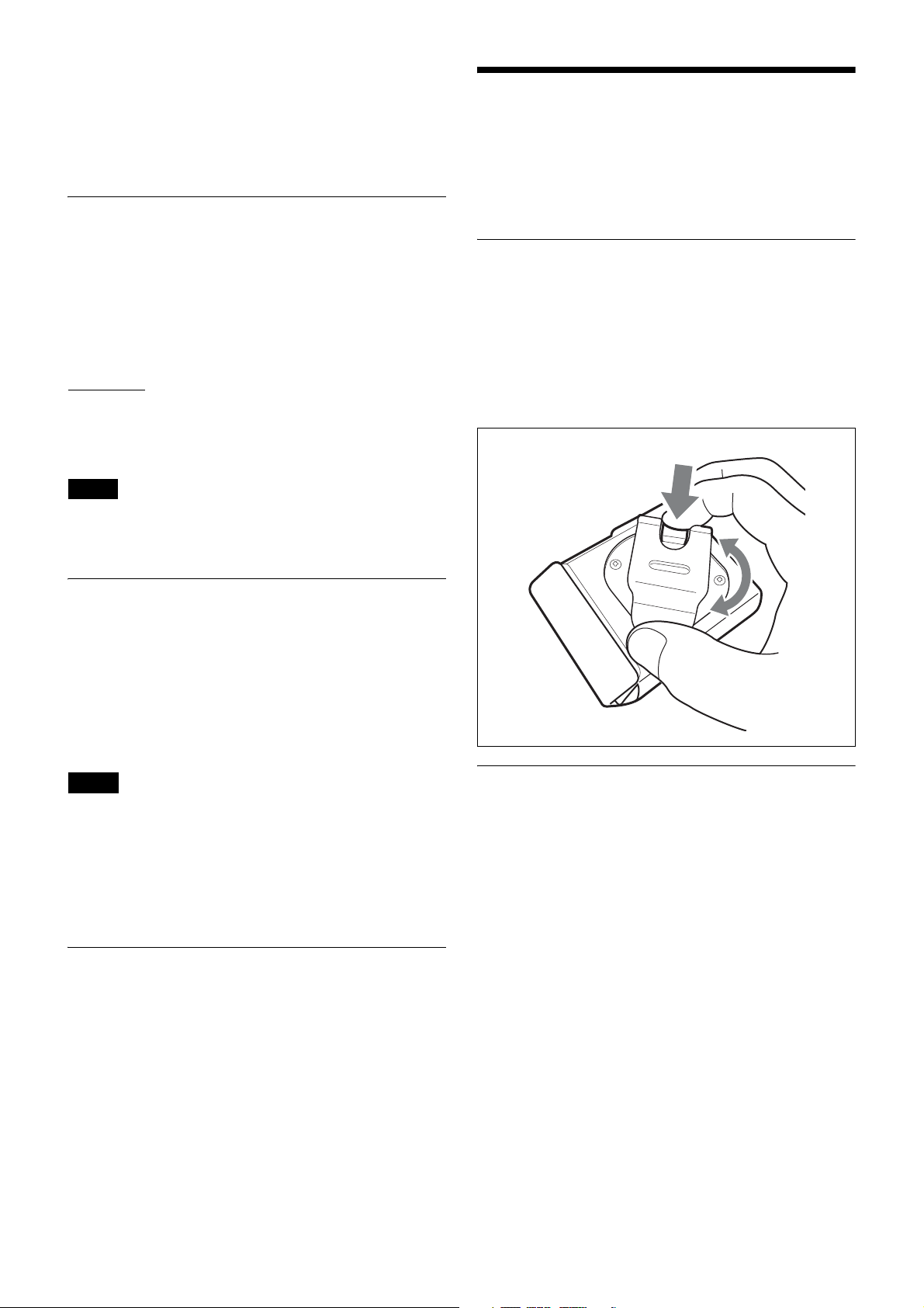
When changing the direction of the belt clip, rotate the clip
while pressing the switch at the top of the clip, and make
sure that the clip is locked into place at your desired
position.
Resetting parameters to their factory
settings
All parameter settings can be returned to their factory
settings.
Holding down the SET button until a message appears
asking for confirmation. Press the + or – button repeatedly
to select YES, and then press the SET button to enter. The
transmitter parameters are reset to their factory settings.
Notes
• The setting for this function cannot be changed during
actual signal transmission. To change the setting, turn
off the power first. Then while holding down the SET
button, turn the power on. Then change the setting after
the signal transmission has stopped.
• To start signal transmission with the factory parameter
settings, turn off the power and then turn it on again.
(FACTORY PRESET)
Displaying the software version
(VERSION)
The version of the transmitter software can be displayed.
Wrapping the microphone cable
around the soft case
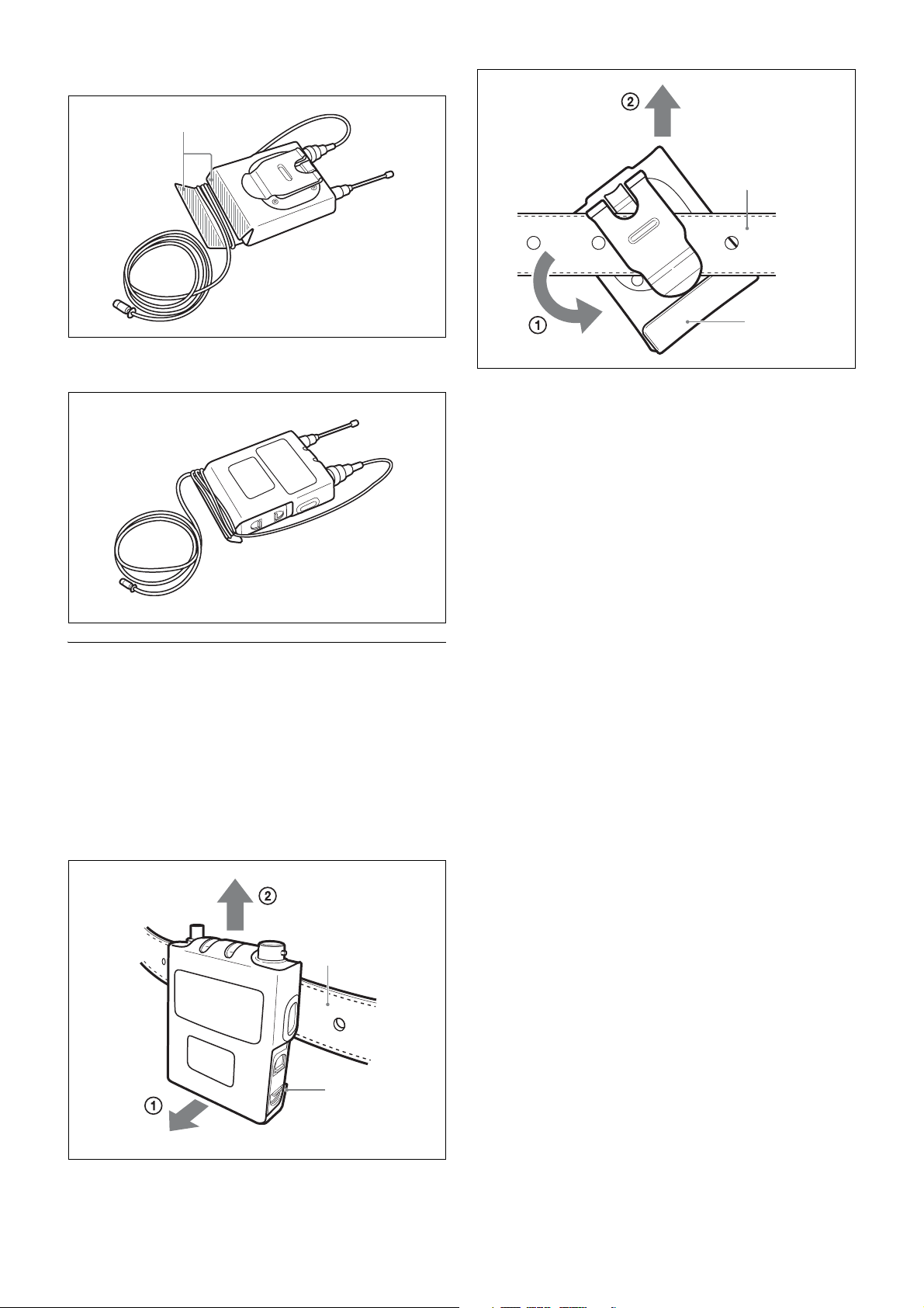
A hook and loop fastener is located at the bottom rear of
the soft case for securing the lavalier microphone’s cable
after the unit is inserted into the case.
By wrapping the microphone cable that is connected to the
unit around this fastener, you can adjust the length of the
cable and reduce the stress that is applied to the unit when
the cable is pulled.
14
Page 15
Rear
Front
Fig. 2
Hook and loop fastener
Belt
Hook and loop
fastener
Removing the unit from a belt
When the soft case is attached to a belt with the unit’s
antenna pointing up, be careful to avoid getting the soft
case’s hook and loop fastener caught on the belt during
removal.
The hook and loop fastener may open if it gets caught on
the belt.
To avoid contact between the fastener and belt, tilt the
bottom of the soft case outward (Fig. 1) or rotate the case
to the left or right (Fig. 2) during removal.
Fig. 1
Belt
Hook and loop
fastener
15
Page 16
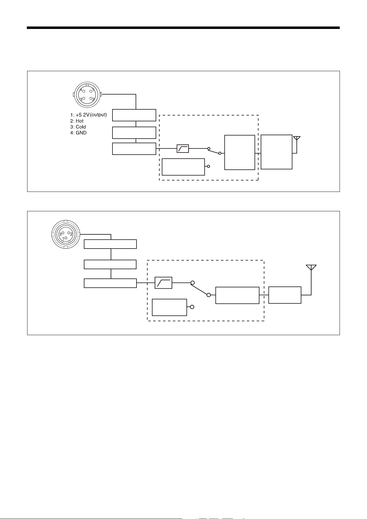
Block Diagram
US model
European model
Attenuator
Head amp.
A/D converter
Digital signal processor
Low-cut filter
Internal SG
Audio
codec
modulator
High-
frequency
circuit
1: GND
2: +5.2 V
(output)
3: Hot +5.2 V
Attenuator
Head amp.
A/D converter
Low-cut
filter
Internal SG
Digital signal processor
Audio codec
modulator
High-
frequency
circuit
16
Page 17
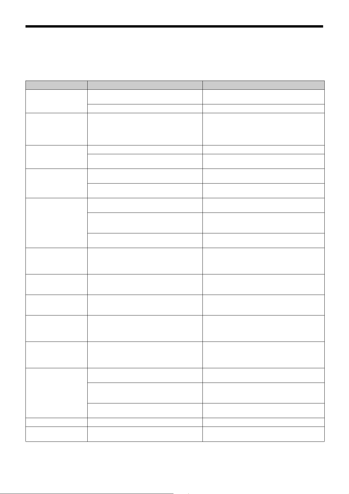
Troubleshooting
If you encounter a problem using this transmitter, use the following checklist to find a solution. For any problems with the
receiver or adapter, refer to the operating instructions supplied with the respective device. If the problem persists, consult
your Sony dealer.
Symptom Meanings Remedy
The transmitter does not
turn on.
The power is repeatedly
turned ON/OFF (screen
turns on/off) even when
the POWER switch is
ON.
The batteries drain
quickly.
Interruptions in the
reception occurs.
There is no sound. The channel setting on the transmitter is
The sound is weak. The audio input level of the transmitter is set to
There is distortion in the
sound.
The bass is weak. The frequency of the low-cut filter is set too
There is too much bass. The microphone connected to the transmitter
The power does not turn
off even though the
POWER switch is turned
to OFF.
Wireless remote control
is not possible.
The display is too dark. The display brightness is set to low. Adjust the brightness of the display (see page 13).
The RF output power
cannot be configured.
The batteries are inserted backwards in the
battery compartment.
The batteries are exhausted. Replace the batteries with new ones.
The batteries are exhausted. Replace the batteries with new ones.
Manganese batteries are being used. Use alkaline batteries.
The transmitter is being used under cold
conditions.
The transmitter is too far from the receiver. Decrease the distance to the receiver and check
The transmission power setting is set to “L:
1mW”.
different from that on the receiver.
The setting of the encrypted transmission
function on the receiver is different from that on
the transmitter.
The audio codec mode settings on the receiver
and transmitter do not match.
LINE or the attenuation level is too high.
The attenuator is set too low for the audio input
level of the transmitter.
high.
produces excessive bass because the
frequency response of the transmitter extends
into the low 20-Hz range.
The POWER switch is locked. Turn off the LOCK function (see page 11).
Pairing has not been established between the
transmitter and receiver.
The receiver is too far from the transmitter for
communication to occur.
The transmitter that was paired with the receiver
has been paired with another receiver.
The maximum RF output power function may be
t to limit the RF output power.
se
Reinsert the batteries with the correct orientation
(see page 5).
The batteries drain quickly under cold conditions.
the reception.
Increase the transmission power (see page 12).
Use the same channel setting on both the
transmitter and receiver.
Confirm that the setting of the encrypted
transmission function is the same on both the
transmitter and the receiver (see page 8).
Configure the same audio codec mode setting for
both the receiver and transmitter (see page 12).
If a microphone is connected to the transmitter, set
the audio input to MIC (see page 12). While
monitoring the audio input level meter, set the
attenuator to an appropriate level.
While monitoring the audio input level meter, set
the attenuator to a level that does not produce
distortion.
While monitoring the sound, decrease the low-cut
filter frequency to a level that produces the proper
sound quality (see page 10).
Use the low-cut filter to cut the bass (see page 10).
Carry out pairing (see page 7).
Check the wireless remote control condition level.
If it is low, decrease the distance between the
transmitter and the receiver (see page 5).
On the receiver, carry out pairing again with the
transmitter that you want to control.
Check and adjust the setting.
17
Page 18

Important Notes on Operation
Notes on using the transmitter
• The digital wireless microphone system product must be
used within a temperature range of 0 °C to 50 °C (32 °F
to 122 °F).
• Operating the transmitter near electrical equipment
(motors, transformers, or dimmers) may cause it to be
affected by electromagnetic induction. Keep the
transmitter as far from such equipment as possible.
• The presence of the lighting equipment may produce
electrical interference over the entire frequency range.
Position the transmitter so that interference is
minimized.
• To avoid degradation of the signal-to-noise ratio, do not
use the transmitter in noisy places or in locations subject
to vibration, such as the following:
- near electrical equipment, such as motors,
transformers or dimmers
- near air conditioning equipment or places subject to
direct air flow from an air conditioner
- near public address loudspeakers
- where adjacent equipment might knock against the
tuner
Keep the transmitter as far from such equipment as
possible or use buffering material.
the antenna of a receiver for up to 10 channels, and at
least 6 meters (20 feet) away for 11 or more channels.
• When a mixture of digital and analog wireless
microphones is being used, keep the transmitter at least
6 meters (20 feet) away from the antenna of a receiver.
• This system should be kept at least 100 meters (328 feet)
away from any analog wireless systems using the same
frequency when both are being used in a wide area with
no walls or obstructions.
• If you experience noise, increase the distance between
the transmitter and receiver or decrease the transmission
power on the transmitter.
Note on microphone and transmitter
combinations
It is recommended that you use the ECM-90BC, ECM90LM, ECM-77LM, ECM-77BC/9X, ECM-66BC/9X,
ECM-44BC/9X, or ECM-FT5BC. Sony lavelier
microphone with this transmitter. The transmission signal
may cause noise on some microphones. If you experience
noise, you may be able to reduce it by changing the
position of the microphone cable, moving the microphone
connection away from the antenna, or lowering the
transmission power.
To prevent electromagnetic interference from portable
communication devices
The use of portable telephones and other communication
devices near the DWT-B30 may result in malfunction and
interference with audio signals. It is recommended that
portable communication devices near the DWT-B30 be
turned off.
On cleaning
• If the transmitter is used in a very humid or dusty place
or in a place subject to an active gas, clean its surface as
well as the connectors with a dry, soft cloth soon after
use. Lengthy use of the transmitter in such places or not
cleaning it after its use in such places may shorten its
life.
• Clean the surface and the connectors of the transmitter
with a dry, soft cloth. Never use thinner, benzene, alcohol
or any other chemicals, since these may mar the finish.
Notes on simultaneous multichannel operation
•
Keep the microphone at least 30 cm (11 7/8 inches) away
from another transmitter/microphone.
When the distances between transmitters need to be
closer than the distances above, use a grouping system
for multi-channel systems that include both digital
wireless and analog wireless devices.
For details, refer to “Sony Digital Wireless Microphone
System Frequency Lists” on the supplied CD-ROM.
CROSS REMOTE Compatibility
As the unit supports a wider band than previous
transmitters, establishing wireless remote communication
via CROSS REMOTE between the unit and DWX-series
devices requires firmware update for the receiver and
RMU-01 unit.
For details on updating the firmware on the DWX-series
receiver or RMU-01 unit, contact your Sony
representative.
For details on how to check the software version, refer to
the device’s operating instructions.
Applicable devices and versions
• DWR-R01D: Version: 1.28 or earlier
• DWR-S01D: Version: 1.16 or earlier
• DWR-R02D: Version: 1.09 or earlier
• DWR-S02D: Version: 1.07 or earlier
• DWR-R02DN: Version 1.18 or earlier
• DWR-S02DN: Version 1.18 or earlier
• RMU-01: Version 1.26 or earlier
• When only digital wireless microphones are being used,
keep the transmitter at least 4 meters (13 feet) away from
18
Page 19
Specifications
Transmitting section
Oscillator type Crystal-controlled PLL synthesizer
RF power output
2 mW/10 mW/25 mW (e.r.p) selectable
Antenna type λ/4 flexible wire
Occupied RF bandwidth
192 kHz or less
Audio delay MODE1: 0.8 ms
MODE2: 0.7 ms
MODE3: 1.8 ms
MODE4: 0.7 ms
Allowable deviation of transmission frequency
±6.5 ppm
Type of emission
G1E or G1D
Modulation method
π/4 Shift QPSK
Audio section
Maximum input level
MIC: –22 dBu (with 0 dB attenuator)
LINE: +24 dBu
Audio attenuator adjustment range (pad)
0 dB to 48 dB (3 dB steps, MIC input
mode only)
Microphone input connector
US model: Sony 4-pin (SMC9-4S)
(female)
European model: Small 3-pin connector
with lock
Input impedance
4.7 kohms or more
Frequency response
20 Hz to 22,000 Hz
T.H.D MODE1, MODE2, MODE4: 0.03% or
less
Dynamic range 106 dB or more
0 dBu = 0.775 V
General
Operating voltage
3.0 V DC (2 x AA alkaline batteries)
5.0 V DC (USB power source)
Consumption current
Max. 450 mA DC (at 3V DC, 25 mW
antenna power)
Battery life Continuous operating time
6.5 hours (at 25 °C (77 °F), 10-mW
output using Sony LR6 (AA)-size
alkaline batteries with CODEC
MODE set to MODE1 and the wireless
remote control function off and
DIMMER MODE set to AUTO OFF)
Operating temperature
0°C to 50°C (32°F to 122°F)
Note
When used in locations with an ambient
temperature of 45 °C (113 °F) or higher,
make sure the unit does not come into
direct contact with your skin, as it may
cause burns due to high temperature.
Storage temperature
–20 °C to +60 °C (–4 °F to +140 °F)
Wireless remote control
2.4-GHz IEEE802.15.4 compliant
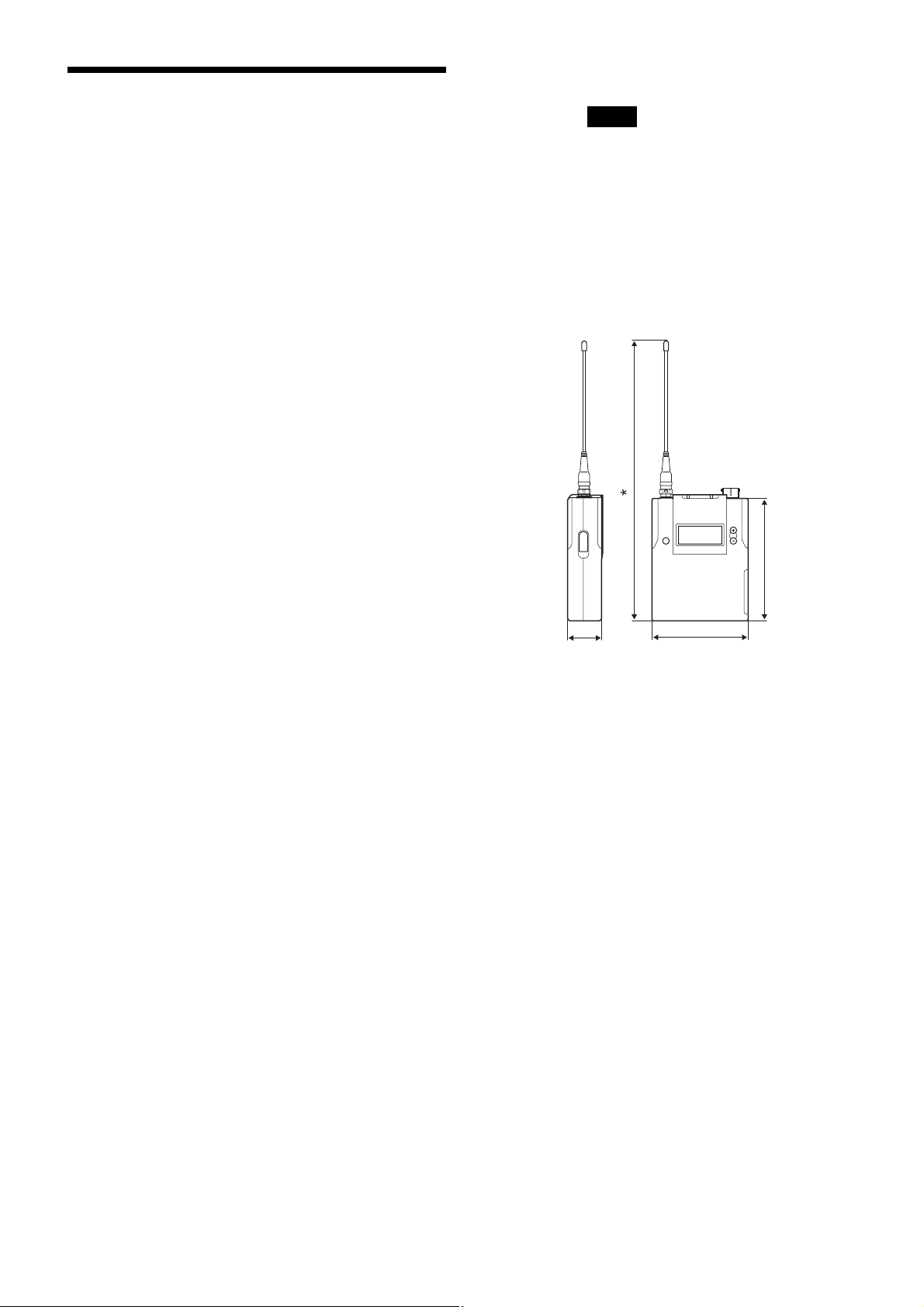
Dimensions (unit: mm (inches))
)
8
/
7
73 (2
17 (11/16)
* 204 (8 1/8)
63 (2 1/2)
Mass Approx. 125 g (4.4 oz)
Including batteries, not including
microphone
Supplied accessories
Spare battery case (1)
Soft case (1)
Microphone cable (4-pin to XLR-type 3-
pin, US model only) (1)
Carrying case (1)
Scribble sheet (1)
Before Using this Unit (3)
CD-ROM (1)
Optional accessories
ECM-90BC, ECM-90LM, ECM-77LM,
ECM-77BC/9X, ECM-66BC/9X,
ECM-44BC/9X, and ECM-FT5BC
lavalier microphones
Design and specifications are subject to change without
notice.
19
Page 20

Notes
• Always verify that the unit is operating properly before use.
SONY WILL NOT BE LIABLE FOR DAMAGES OF ANY
KIND INCLUDING, BUT NOT LIMITED TO,
COMPENSATION OR REIMBURSEMENT ON ACCOUNT
OF THE LOSS OF PRESENT OR PROSPECTIVE PROFITS
DUE TO FAILURE OF THIS UNIT, EITHER DURING THE
WARRANTY PERIOD OR AFTER EXPIRATION OF THE
WARRANTY, OR FOR ANY OTHER REASON
WHATSOEVER.
• SONY WILL NOT BE LIABLE FOR CLAIMS OF ANY
KIND MADE BY USERS OF THIS UNIT OR MADE BY
THIRD PARTIES.
• SONY WILL NOT BE LIABLE FOR THE TERMINATION
OR DISCONTINUATION OF ANY SERVICES RELATED
TO THIS UNIT THAT MAY RESULT DUE TO
CIRCUMSTANCES OF ANY KIND.
20
Page 21
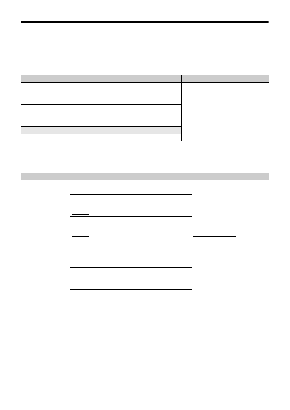
Carrier Frequencies and Channel Steps
Underlined values represent factory settings.
US model
Channel step: 25 kHz
Frequency band Frequency Group/channel (factory setting)
TV14-17 470.125 - 493.875 MHz 00 1801 494.125 MHz
TV18-21 494.125 - 517.875 MHz
TV22-25 518.125 - 541.875 MHz
TV26-29 542.125 - 565.875 MHz
TV30-33 566.125 - 589.875 MHz
TV34-36 590.125 - 607.875 MHz
TV37 Not available
TV38 614.125 - 615.875 MHz
The maximum transmission power (MAX RF POWER) for TV38 (614.125 - 615.875 MHz) is 10 mW.
European models
Channel step: 25 kHz
Model No. Frequency band Frequency Group/channel (factory setting)
L
(TV21-TV38)
H
(TV33-TV51)
TV21-23
TV24-26 494.025 - 518.000 MHz
TV27-29 518.025 - 542.000 MHz
TV30-32 542.025 - 566.000 MHz
TV33-35
TV36-37 590.025 - 606.000 MHz
TV38 606.025 - 614.000 MHz
TV33-35
TV36-37 590.025 - 606.000 MHz
TV38 606.025 - 614.000 MHz
TV38-40 606.025 - 630.000 MHz
TV41 630.025 - 638.000 MHz
TV42-44 638.025 - 662.000 MHz
TV45-47 662.025 - 686.000 MHz
TV48-50 686.025 - 710.000 MHz
TV51 710.025 - 714.000 MHz
470.025 - 494.000 MHz 00 2101 470.125 MHz
566.025 - 590.000 MHz
566.025 - 590.000 MHz 00 3301 566.125 MHz
21
Page 22

Sony Corporation
 Loading...