

Page 1

DVS-9000/9000SF System
(With CCP-9000 Series Center Control Panel)
User’s Guide
Production Switcher System
Volume 2 [English]
1st Edition
Software Version 1.30 and Later
Page 2

NOTICE TO USERS
© 2002 Sony Corporation. All rights reserved. This
manual or the software described herein, in whole or in
part, may not be reproduced , translated or reduced to
any machine read ab le f orm with out prior written appr ov a l
from Sony Corporation.
SONY CORPORATION PROVIDES NO WARRANTY
WITH REGARD TO THIS MANUAL, THE SOFTWARE
OR OTHER INFORMATION CONT AI NED HEREIN AND
HEREBY EXPRESSLY DISCLAIMS ANY IMPLIED
WARRANTIES OF MERCHANTABILITY OR FITNESS
FOR ANY PARTICULAR PURPOSE WITH REGARD TO
THIS MANUAL, THE SOFTWARE OR SUCH OTHER
INFORMATION. IN NO EVENT SHALL SONY
CORPORATION BE LIABLE FOR ANY INCIDENTAL,
CONSEQUENTIAL OR SPECIAL DAMAGES,
WHETHER BASED ON TORT, CONTRACT, OR
OTHERWISE, ARISING OUT OF OR IN CONNECTION
WITH THIS MANUAL, THE SOFTWARE OR OTHER
INFORMATION CONTAINED HEREIN OR THE USE
THEREOF.
Sony Corporation reserves the right to make any
modification to this manual or the information contained
herein at any time without notice.
The software described herein may also be gover ned by
the terms of a separate user license agreement.
Page 3

Table of Contents
Chapter 11 DME Operations
Chapter 12 External Devices
Basic Operation for External Device Control............................................10
Saving Control Setting Data in Registers..............................................10
Amending Keyframes............................................................................11
Carrying Out Control of External Devices............................................12
Control of P-BUS Devices............................................................................14
Editing the P-BUS Timeline..................................................................14
P-BUS Trigger.......................................................................................16
Chapter 13 Keyframe Effects
Sequence of Keyframe Operations..............................................................20
Recalling a Register......................................................................................21
Specifying the Region and Edit Points........................................................23
Creating and Editing Keyframes................................................................25
Creation .................................................................................................25
Insertion.................................................................................................26
Modification..........................................................................................26
Deletion .................................................................................................30
Movement..............................................................................................31
Copying .................................................................................................32
Pause......................................................................................................33
Undoing an Edit Operation....................................................................33
Duration Mode Setting..........................................................................33
Time Settings.................................................................................................34
Setting the Keyframe Duration..............................................................34
Setting the Effect Duration....................................................................35
Setting the Delay ...................................................................................36
Path Setting...................................................................................................37
Basic Procedure for Path Settings.........................................................37
Executing Effects..........................................................................................41
Execution With the RUN Button (Auto Mode).....................................41
Run Mode Setting..................................................................................42
Saving Effects................................................................................................44
3Table of Contents
Page 4

Register Operations in the Menus...............................................................46
Effect Status Display.............................................................................46
Effect Register Editing..........................................................................46
Chapter 14 Snapshots
Snapshot Operations From the Numeric Keypad Control Block............50
Saving and Recalling Snapshots............................................................51
Snapshot Operations in the Menus.............................................................55
Setting Snapshot Attributes...................................................................55
Snapshot Status Display........................................................................57
Setting Key Snapshot Attributes ...........................................................58
Snapshot Register Editing.....................................................................58
Chapter 15 Shot Box
Shot Box Register Creation.........................................................................64
Shot Box Execution.......................................................................................67
Shot Box Execution From the Numeric Keypad Control Block...........67
Shot Box Execution in the Utility/Shot Box Control Block .................69
Shot Box Register Editing............................................................................71
Chapter 16 Engineering Setup
Setup for the Whole System.........................................................................75
Network Settings (Network Config Menu)...........................................75
System Settings (System Config Menu) ...............................................76
Setting the Signal Format and Screen Aspect Ratio (Format Menu) ....78
Selecting the State After Powering On (Start Up Menu)......................79
Reset and Initialization (Initialize Menu)..............................................81
Installation (Install Menu).....................................................................82
System Maintenance (Maintenance Menu)...........................................82
Setup Relating to Operations From the Control Panel.............................85
Overall Control Panel Settings (Config Menu).....................................85
Cross-Point Settings (Xpt Assign Menu)..............................................90
AUX Delegation Buttons Settings (Aux Assign Menu) .......................94
Interfacing With External Devices (Device Interface Menu)................95
Operation Settings (Operation Menu)...................................................99
Screen Saver and Other Settings (Maintenance Menu).......................101
Setup Relating to Switcher Processor.......................................................103
Settings for Switcher Configuration (Config Menu)...........................103
Signal Input Settings (Input Menu).....................................................106
Table of Contents
4
Page 5

Signal Output Settings (Output Menu)................................................107
Settings Relating to Video Switching (Transition Menu)...................110
Settings Relating to Keys, Wipes and Frame Memory (Key/Wipe/FM
Menu).......................................................................................112
Settings Relating to Function Links (Link Menu)...............................114
Interfacing With External Devices (Device Interface Menu)..............118
Setup Relating to DME..............................................................................123
Settings Relating to Signal Inputs (Input Menu).................................123
Interfacing With External Devices (Device Interface Menu)..............124
Setup Relating to DCU...............................................................................127
Settings Relating to Signal Inputs (Input Config Menu).....................127
GPI Input Setting (GPI Input Assign Menu).......................................128
Signal Output Settings (Output Config Menu)....................................130
GPI Output Setting (GPI Output Assign Menu) .................................132
Setup Relating to Router Interface and Tally..........................................134
Router Interface Settings (Router Menu)............................................134
Tally Group Settings (Group Tally Menu)..........................................136
Wiring Settings (Wiring Menu) ..........................................................137
Tally Generation Settings (Tally Enable Menu) .................................139
Tally Copy Settings (Tally Copy Menu).............................................140
Parallel Tally Settings (Parallel Tally Menu)......................................142
Simple Connection of the MKS-8080/8082 AUX Bus Remote Panel.....145
Procedure for Simple Connection .......................................................145
Setting Status of the MKS-8080/8082 in Simple Connection............. 146
Chapter 17 Files
Operations on Individual Files..................................................................148
File Batch Operations.................................................................................155
Selecting Regions................................................................................149
Selecting the Recording Medium........................................................149
Saving Files.........................................................................................150
Recalling Files.....................................................................................150
Copying Files ............................... ...... .................................................151
Moving Files........................................................................................152
Deleting Files ..................................... ..... ...... ......................................153
Renaming Files....................................................................................154
Batch Saving Files ...............................................................................155
Batch Recalling Files...........................................................................155
5Table of Contents
Page 6

Chapter 18 DIAGNOSIS
Appendix
Wipe Pattern List .......................................................................................160
Standard Wipes....................................................................................160
Enhanced Wipes..................................................................................161
Rotary Wipes.......................................................................................162
Mosaic Wipes......................................................................................163
Random/Diamond Dust Wipes............................................................165
DME Wipe Pattern List................................. ...... ......................................166
DME Wipe Patterns Available in One-Channel Mode.......................166
DME Wipe Patterns Available in Two-Channel Mode.......................170
Menu Tree...................................................................................................171
Recalling Menus..................................................................................171
M/E-1 to M/E-3 Menus.......................................................................171
PGM/PST Menu..................................................................................173
Frame Memory Menu..........................................................................174
Color Bkgd Menu................................................................................174
AUX/MON Menu................................................ ..... ...........................175
Copy/Swap Menu................................................................................175
MISC Menu.........................................................................................175
DME Menu..........................................................................................176
Device Menu ....................................................... ..... ...........................177
Key Frame Menu.................................................................................177
Effect Menu.........................................................................................178
Snapshot Menu....................................................................................179
Shotbox Menu .....................................................................................180
File Menu ............................................................................................181
Engineering Setup Menu.....................................................................182
Table of Contents
6
Index ...........................................................................................................185
Page 7

Chapter 11 DME Operations
Not supported in version 1.30.
Page 8

Chapter 11 DME Operations
8
Page 9

Chapter 12 External Devices
Basic Operation for External Device Control......................................10
Saving Control Setting Data in Registers........................................10
Amending Keyframes......................................................................11
Carrying Out Control of External Devices...................................... 12
Control of P-BUS Devices......................................................................14
Editing the P-BUS Timeline............................................................14
P-BUS Trigger.................................................................................16
Page 10

Basic Operation for External Device
Control
Use the Device menu to carry out operations for controlling external devices
such as devices supporting P-BUS (Peripheral II protocol) (referred to as “PBUS devices” in the manual), and VTRs.
For VTRs only, you can also carry out operations using the device control
block.
Accessing the Device menu
In the menu control block, press the top menu selection button [DEV].
Chapter 12 External Devices
Saving Control Setting Data in Registers
For P-BUS devices, you can save the action settings in a register.
This section describes the procedure for saving a P-BUS timeline edited in the
Device menu into a register.
For more details of the method of editing a P-BUS timeline, see “Editing the
P-BUS Timeline” (page 14).
1
In the keyframe control block, press the [EDIT ENBL] button, turning it
on.
2
In the numeric keypad control block, press the [EFF] button, turning it on.
This assigns the numeric keypad control block to keyframe operations, and
the [RCALL] button lights.
3
Press the [P-BUS] button in the numeric keypad control block, turning it
on, to select the P-BUS region.
4
Enter the number of the register to be recalled with the numeric keypad
buttons.
To search for an empty register, instead of entering a number , press the “.”
(period) button.
The display shows the register number. A letter “e” or “E” after the number
indicates the register status, as follows:
Basic Operation for External Device Control
10
Page 11

e: This register is empty in the selected region.
E: This register is empty in all selectable regions.
5
Press the [ENTER] button.
This recalls the register you selected in step 4.
6
In the Device menu, press VF2 ‘P-BUS Timeline.’
The Device>P-Bus Timeline menu appears.
The status area shows a window for setting the action for the P-BUS
device.
7
Carry out the action setting.
For more details of how to make the settings, see “Setting an action” (page
14).
8
Press the [INS] button in the keyframe control block.
This inserts the action setting data at the keyframe point.
9
Repeat steps 7 and 8 to create the required number of keyframes.
10
Press the [STORE] button in the numeric keypad control block.
This saves the P-BUS timeline settings in the register.
Chapter 12 External Devices
Amending Keyframes
You can amend a keyframe which has been saved in a register.
To amend a P-BUS timeline keyframe, use the following procedure.
1
In the keyframe control block, press the [EDIT ENBL] button, turning it
on.
2
Press the [EFF] button in the numeric keypad control block, turning it on.
This assigns the numeric keypad control block to keyframe operations, and
the [RCALL] button lights.
11Basic Operation for External Device Control
Page 12

3
Press the [P-BUS] button in the numeric keypad control block, turning it
on, to select the P-BUS region.
4
Enter the number of the register to be recalled, with the numeric keypad
buttons.
5
Using the edit point specification buttons and fader lever in the keyf rame
control block, stop the effect on the desired edit point.
When the edit point is on a keyframe, this is the keyframe to be amen ded;
if the edit point is between two keyframes, the immediately preceding
keyframe is the one to be amended.
6
In the Device menu, press VF2 ‘P-Bus Timeline.’
The Device>P-Bus Timeline menu appears.
Chapter 12 External Devices
The status area shows a window for setting the action for the P-BUS device
at the edit point specified in step 5.
7
Change the setting of the action for the edit point.
For more details of making the change, see “Sett ing an action” (page 14).
8
Press the [MOD] button.
Carrying Out Control of External Devices
By recalling a register containing setting data for external device control, as
when automatically executing a keyframe effect, you can automatically contr ol
an external device.
Use the following procedure.
1
In the numeric keypad control block, press the [EFF] button, turning it on.
The [RCALL] button in the numeric keyp ad control block lights.
2
Press the [P-BUS] button in the numeric keypad control block, turning it
on, to select the P-BUS region.
3
Enter the number of the register to be recalled with the numeric keypad
buttons.
4
Press the [RUN] button in the keyframe control block, lighting it amber.
This controls the external device according to the keyframe data.
Basic Operation for External Device Control
12
Page 13

To move to the first keyframe
To move to the first keyframe, press the [REWIND] button in the keyframe
control block.
If an action is set for a rewind operation, then the action is carried out. (See
“Setting an action for the rewind operation” (page 16).)
Chapter 12 External Devices
13Basic Operation for External Device Control
Page 14

Control of P-BUS Devices
Editing the P-BUS Timeline
This section describes how to set an action for a keyframe point, and edit the
P-BUS timeline.
Note
Using the P-BUS timeline function requires the P-BUS control mode to be set
to [Timeline]. Carry out this setting in the Engineering Setup>Panel>Device
Interface menu.
Chapter 12 External Devices
Setting an action
To set an action, use the following procedure.
1
In the Device menu, press VF2 ‘P-Bus Timeline.’
The Device>P-Bus Timeline menu appears.
The status area shows two lists. The left list is for setting combinations of
devices and actions. The setti ngs in this list will be s aved as keyframe point
data. The right list is for selecting the action.
2
Using any of the following methods, select the P-BUS device for which
you want to set an action.
Control of P-BUS Devices
14
• Press directly on the left list appearing in the status area.
• Press the arrow keys to scroll the reverse video cursor.
• Turn knob 1 to make the setting.
Knob Parameter Adjustment Setting values
1 Device No. Device number 1 to 24
3
Using either of the following methods, select the action.
• Press directly on the right list in the status area.
• Turn knob 2 to make the setting.
Knob Parameter Adjustment Setting values
2 Action No. Action
a) 1: Off (no specification)
2: Store
1 to 4
a)
Page 15
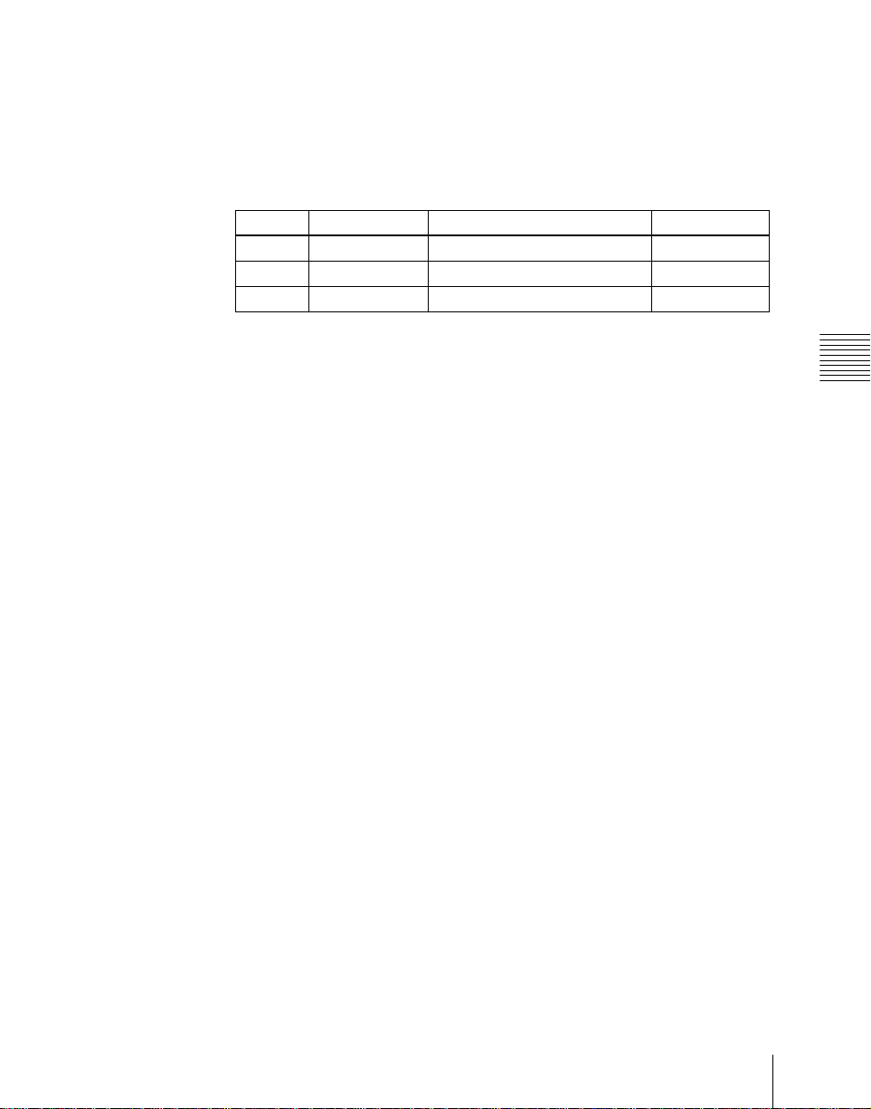
3: Recall
4: Trigger
4
If in step 3 you selected 2 (Store), 3 (Recal l), or 4 (Trigger), tur n knob 3 to
select the register number or trigger number.
The indication for knob 3 changes to reflect the s election of Store, Recall,
or Trigger.
Knob Parameter Adjustment Setting values
3 Store No. Register number for Store 1 to 99
3 Recall No. Register number for Recall 1 to 99
3 Trigger No. Trigger number 0 to 15
The setting is reflected in the list on the right of the status area.
5
Press [Set].
For the device selected in the list on the left of the status area, this sets the
action specified in step 4.
Repeat steps 2 to 5 as required for other devices.
Testing an action command
You can check the set action in the Device menu.
To produce a test output of the action command, press [Test Fire].
The action command is output from the 9-pin serial port of the DCU-8000
Device Control Unit according to the setting in the list on the left of the status
area.
Chapter 12 External Devices
Clearing an action setting
To clear the setting for separate devices
Use the following procedure.
1
In the list on the left of the status area, select the device fo r which you want
to clear the action setting.
2
In the list on the right, select “Off.”
3
Press [Set].
To clear the action settings for all devices in a single operation
Press [All Off].
15Control of P-BUS Devices
Page 16

Setting an action for the rewind operation
In order that when recalling a P-BUS timeline, pres sing the [REWI ND] button
in the keyframe control block moves to the first keyframe, an action setting
must be made for this.
In the Device>P-Bus Timeline menu, press [Rewind Action], and make the
setting in the window that appears. In this setting window, the method of
setting is the same as in the window for making an action setting on the P-BUS
timeline.
P-BUS Trigger
“P-BUS trigger” is a function whereby a button operation in the numeric
keypad control block or keyframe control b lock outp uts an actio n command to
Chapter 12 External Devices
a P-BUS device.
Note
To use the P-BUS trigger function, the P-BUS control mode must be set to
[Trigger]. Make this setting in the Engineering Setup>Panel>Device Interface
menu (see page 99).
The relation between the operation in each of the control blocks and the action
command output is as follows.
Action command for an operation in the numeric keypad control
block
• RECALL: Recall
•STORE: Store
This recalls the register specified in the numeric keypad control block, and a
Recall or Store is carried out, according to the setting.
Action command for an operation in the keyframe control block
• RUN: Trigger 1
• REWIND: Trigger 4
• NEXT KF: Trigger 7
• PREV KF: Trigger 8
Outputting an action command
As an example, to output a Recall, use the following procedure.
1
In the numeric keypad control block, press the [EFF] button, turning it on.
The [RCALL] button in the numeric keyp ad control block lights.
Control of P-BUS Devices
16
Page 17

2
Press the [P-BUS] button in the numeric keypad control block, turning it
on, to select the P-BUS region.
3
Enter the number of the register to be recalled with the numeric keypad
buttons.
4
Press the [ENTER] button in the numeric keypad control block.
This carries out the Recall.
Chapter 12 External Devices
17Control of P-BUS Devices
Page 18

Chapter 12 External Devices
Control of P-BUS Devices
18
Page 19

Chapter 13 Keyframe Effects
Sequence of Keyframe Operations........................................................ 20
Recalling a Register................................................................................ 21
Specifying the Region and Edit Points........................... ....................... 23
Creating and Editing Keyframes ..........................................................25
Creation ...........................................................................................25
Insertion...........................................................................................26
Modification ....................................................................................26
Deletion ...........................................................................................30
Movement........................................................................................31
Copying ........................................................................................... 32
Pause................................................................................................ 33
Undoing an Edit Operation..............................................................33
Duration Mode Setting ....................................................................33
Time Settings...........................................................................................34
Setting the Keyframe Duration........................................................34
Setting the Effect Duration..............................................................35
Setting the Delay .............................................................................36
Path Setting.............................................................................................37
Basic Procedure for Path Settings ...................................................37
Executing Effects ........................................................ ..... ....................... 41
Execution With the RUN Button (Auto Mode)...............................41
Run Mode Setting............................................................................42
Saving Effects..........................................................................................44
Register Operations in the Menus.........................................................46
Effect Status Display ........................................... ..... ....................... 46
Effect Register Editing ................................................... ...... ..... ......46
Page 20

Sequence of Keyframe Operations
The following table shows the principal operations involved in the sequence
from creating keyframes to executing an effect. For details of each operation,
see the page number in parenthesis.
For an overview, see “Keyframes” in Chapter 1 (Volume 1).
Recalling a register (see page 21)
To create a new effect, recall an empty register; to edit an effect, open the
register containing it.
v
Specifying the region and edit points (see page 23)
Select the region in which editing applies, and set the edit points.
v
Creating and editing keyframes (page 25)
Create the keyframes that make up the effect, using operations to create,
insert, modify, or delete keyframes.
Chapter 13 Keyfra me Effects
Time settings (see page 34)
Set the overall duration of the effect or the duration of each keyframe.
v
Sequence of Keyframe Operations
20
v
Path setting (see page 37)
Set the type of interpolation used between successive keyframes.
v
Executing effects (see page 41)
This provides a smooth effect, based on the time and path settings.
v
Saving effects (see page 44)
Save a completed effect in a register.
Page 21

Recalling a Register
Use the numeric keypad control block to recall a register. For each region there
are 99 registers dedicated to keyframes, numbered from 1 to 99.
When creating an effect as a user programmable DME, use a 3-digit register
number whi ch is commonly used for all DME regions (channels).
For a description of the concept of regions and registers, see “Regions and
Registers” in Chapter 1 (Volume 1).
Note
To use DME requires the BKDS-9470 DME Board Set.
SNAP
EFF
SHOT
SHOT
BOX
TRANS
RATE
M/E
1
AUX1AUX2AUX3AUX4AUX5AUX6AUX7FMS1FMS2EDIT
MCRO
P/P
MASTR ALL
M/E
1
DME1DME2DME3DME
P-BUS
Display
P/P
GP1
USER1USER
UNDO buttonEFF button
+/-
EFF
9
8
UNDO
STORE
STATS
2
STORE
4
RCALL
7
4
5
2
1
0
DISS
CLR
AUTO
6
TRANS
TRIM
3
GPI
ENBL
ENTER
KEY SHIFT
PVW
Chapter 13 Keyframe Effects
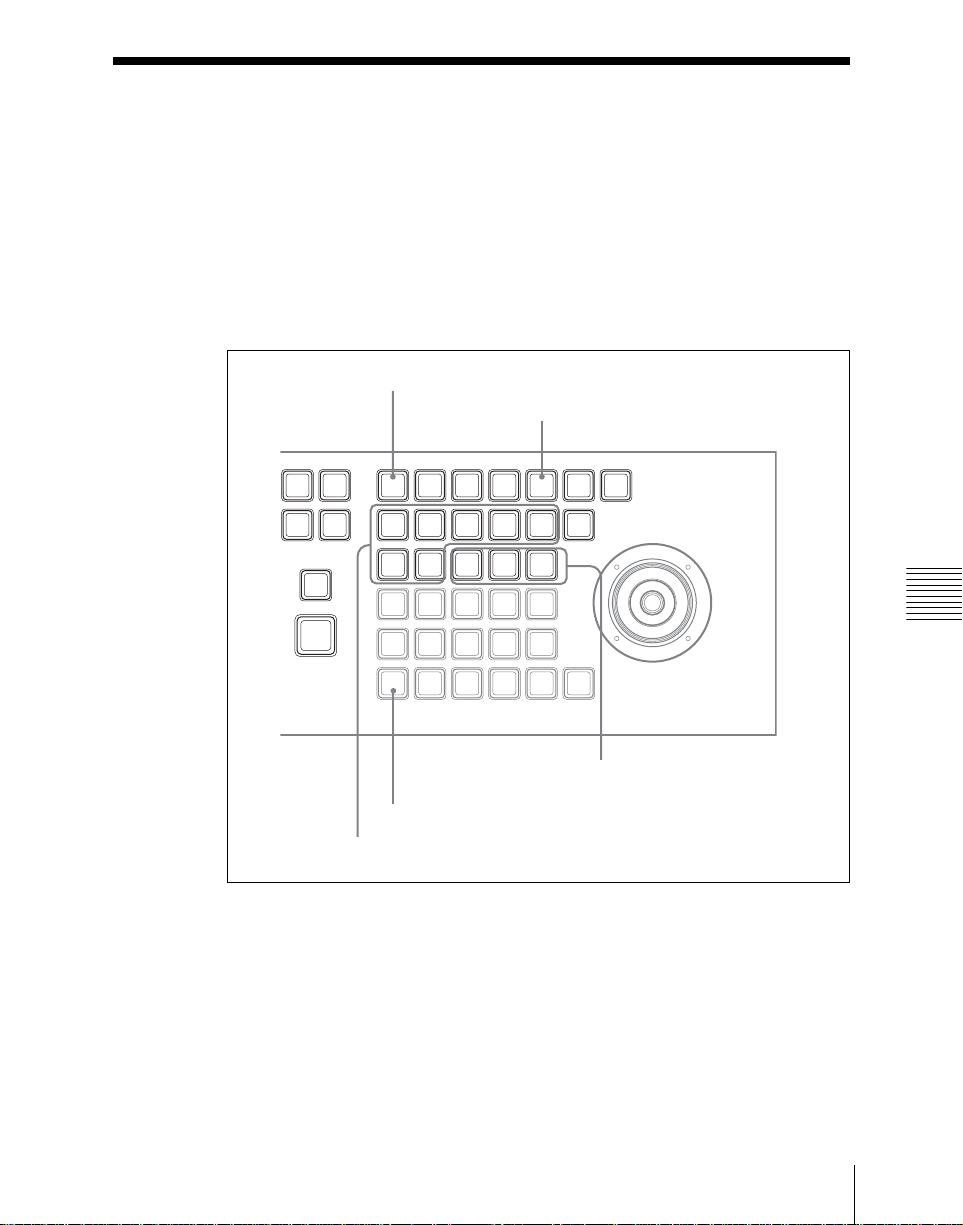
Recalling a register
Use the following procedure.
Numeric keypad
RCALL button
Region selection buttons
Numeric keypad control block
21Recalling a Register
Page 22

1
Press the [EFF] button, turning it on.
This allocates the numeric keypad control block to keyframe operations,
and the [RCALL] button lights.
2
Press the button corresponding to the region you want to select, turning it
on.
You can also press more than one button.
[M/E 1], [P/P]: These select the corresponding M/E-1 and PGM/PST
regions.
[USER 1] to [USER 2]: These select the USER regions.
[DME 1] to [DME 4]: These select DME channels.
[P-BUS]: This selects P-BUS.
[ALL]: This selects all va l id regions.
The first button pressed lights green as the reference region, and any
subsequently pressed buttons light amber.
The display shows the name of the refer ence region, and the number of the
last register recalled for this region.
3
Enter the number of the register you want to recall, using the numeric
keypad.
To find an empty register, instead of entering a number, pres s the [.]
Chapter 13 Keyfra me Effects
(period) button. To search for an empty register common to all currently
selectable regions, press the [.] button again.
To search for an empty register in the 100 range, press [1], [0], [0], [.]
(period) in this order. Similarly, to search for an empty register in the 200
range, press [2], [0], [0], [.] (period).
Recalling a Register
22
The register number appears in the displ ay. If the number is followed by a
letter ‘e’ or ‘E’, this indicates the following.
e: The selected register is empty for the regions selected in step 2.
E: The selected register is empty for all currently selectable regions.
4
Press the [ENTER] button.
This recalls the specified register.
To undo the recall of a register
Immediately after recalling the register, press the [UNDO] button to undo the
operation.
Page 23
Specifying the Region and Edit Points
Selecting the region in which editing applies
Select the region in which the editing is applied by the effect consisting of
keyframes, using the region selection buttons in the numeric keypad control
block. (See step 2 in “Recalling a register” on the previous page.)
Setting the edit points
EDIT ENBL button
CONST DUR button
STOP
LOOP
NORM
/REV
EFF
RE
WIND
RUN
EDIT
NEXT
ENBL
KF
COPY
INS
MENU
AXIS
LOC
SHIFT
EFF
KF
DUR
DUR
PASTEREV
DEL
GOTO
MOD
KF/TC
LOCAL GLB SRC TRGT
ASP
LOC
SKEW
SIZE
PERS
CLR
X
WORK
BUFR
CONST
DELAY
DUR
FROMTORUN
UNDO
NEXT
PREV
KF
KF
LOC
ROT
XYZ
Y Z CTR
KF
PAUSE
LOOP
CTRL
Chapter 13 Keyframe Effects
Buttons also used for editing
SHIFT button
Editing buttons
Keyframe control block
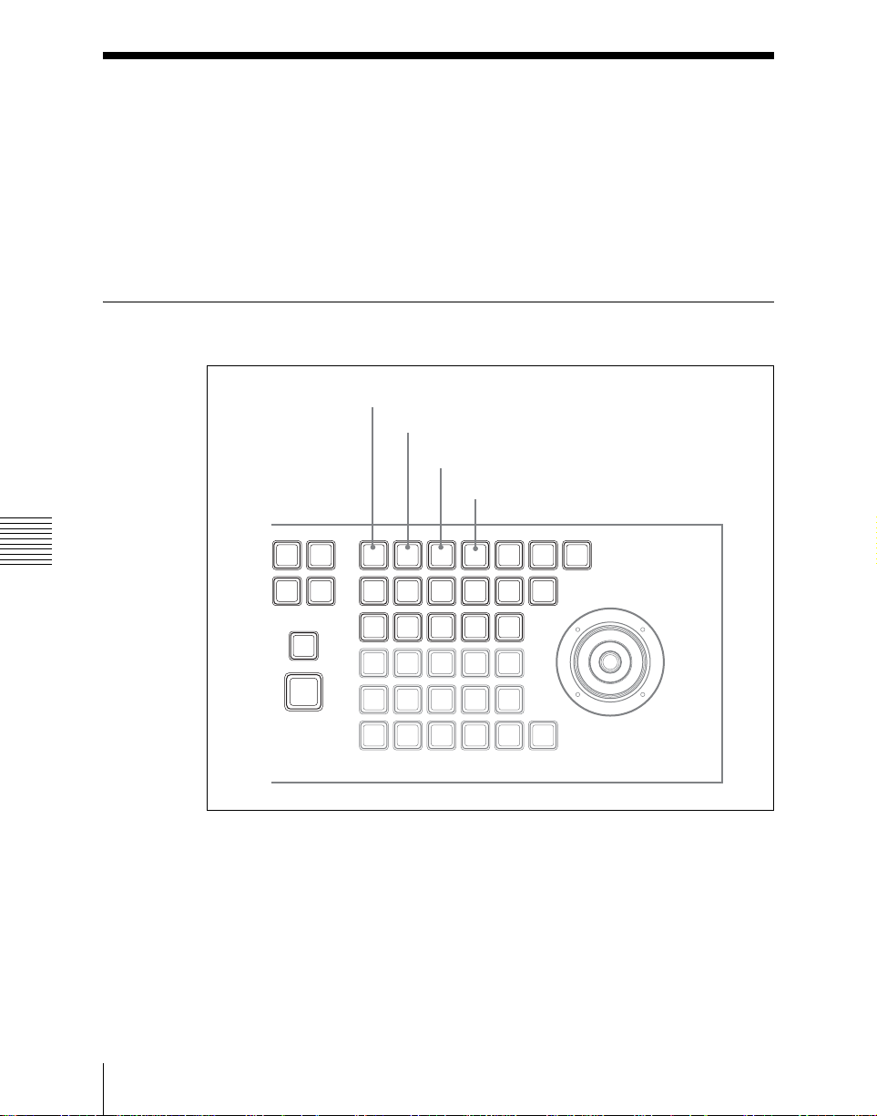
To set the edit points, use any of the following operations in the keyframe
control block.
• To move the edit point to the keyframe immediately after the current time
(the position at which the effect is cu rrently stopped), pres s the [NEXT KF]
button.
• To move the edit point to the keyf rame immediately before the curr ent time,
press the [PREV KF] button.
23Specifying the Region and Edit Points
Page 24

• To move the edit point to a keyframe specified by number, press the [GO TO
KF/TC] button, turning its LED on, then enter the keyframe number with the
numeric keypad in the numeric k eypad control block, and press the [ENTER]
button to confirm.
• To move the edit point to a specified timecode, press the [GO TO KF/TC]
button, turning its LED off, then enter the timecode value with the numeric
keypad in the numeri c key pad control block, and press the [ENTER] button
to confirm.
Entering a difference value
When moving to a point specified with the [GO TO KF/TC] button, you can
also enter the difference from the current keyframe number or timecode valu e.
Press the numeric keypad +/− button, and enter the difference, then press the
[TRIM] button. Each time you press the +/− button, it toggles between plus (+)
and minus (−).
Chapter 13 Keyfra me Effects
Specifying the Region and Edit Points
24
Page 25

Creating and Editing Keyframes
For details of keyframe editing, see “Effect Editing” in Chapter 1 (Volume 1).
Creation
Creating new ke y fr ame s
To create new keyframes, after recalling an empty register, use the following
procedure to create and insert each new keyframe. Use the keyframe control
block for carrying out the operation.
1
Press the [EDIT ENBL] button, turning it on.
This enables effect editing in the keyframe control block.
2
Create the image you want to be the first keyframe.
3
Press the [INS] button.
This takes the current image as the first keyframe.
4
Create the image you want to be the next keyframe.
5
Press the [INS] button.
This inserts the current image as the second keyframe after the first
keyframe.
Repeat steps 4 and 5 to create the required number of keyframes.
To insert a new keyframe before an existing keyframe
Hold down the [SHIFT] button and press the [INS] button, to insert a new
keyframe before the current keyframe.
Chapter 13 Keyframe Effects
25Creating and Editing Keyframes
Page 26

Insertion
Inserting keyframes
To insert a keyframe in an existing effect, use the following procedure in the
keyframe control block.
1
Press the [EDIT ENBL] button, turning it on.
2
Stop the effect at the desired edit point.
3
Create the image for the keyframe you want to insert.
4
Press the [INS] button.
When the edit point is on a keyframe, to insert the new keyframe before
the existing keyframe, hold down the [SHIFT] button and press the [INS]
button.
This inserts the current image as the new keyframe.
Inserting a keyframe may change the total duration of the effect. (See
“Time Settings” in Chapter 1 (Volume 1).)
Chapter 13 Keyfra me Effects
Modification
Modifying keyframes
Use the following procedure in the keyframe control block.
1
Press the [EDIT ENBL] button, turning it on.
2
Stop the effect at the desired edit point.
When the edit point is on a keyframe, this is what you modify. If the edit
point is between two keyframes, the previous keyframe is what you
modify.
Note
In constant duration mode (see “Effect Ed iting” in Chapter 1 (Vol ume 1))
modification is only possible when the edit point is on a keyframe.
Creating and Editing Keyframes
26
Page 27

3
Using image transformations or adding special effects, modify the
keyframe.
4
Press the [MOD] button.
This modifies the keyframe.
Modifying more than one keyframe simultaneously
You can modify a number of keyframes simultaneously. There are three
different cases for this operation.
• Modifying all keyframes after the edit point, or modifying from the edit point
to a particular keyframe
• Modifying all keyframes in the effect
• Modifying the keyframes in a specified range
The different procedures for these cases are now described.
To modify all keyframes after the edit point, or to modify from the
edit point to a particular keyframe
Use the following procedure.
1
Press the [EDIT ENBL] button, turning it on.
2
Stop the effect at the first keyframe of the range to be modified.
3
Carry out the necessary modifications.
Chapter 13 Keyframe Effects
4
Press the [FROM TO] button, turning it on.
The display in the numeric keypad control block shows the current
keyframe number, followed by “TO.”
To modify all of the subsequent keyframes, skip to step 6.
5
To modify up to a particular keyframe, enter the keyframe number with the
numeric keypad in the numeric keypad control block, and press the
[ENTER] button to confirm.
6
Press the [MOD] button. Alternatively, hold down the [SHIFT] button and
press the [MOD] button.
For the difference in the result, see “Differences in the changes when a
number of keyframes are modified” (page 28).
This makes the modification simultaneously to all keyframes up to the
specified keyframe, or to all keyframes from the edit point.
To modify the keyframes in a specified range
Use the following procedure.
27Creating and Editing Keyframes
Page 28

1
Press the [EDIT ENBL] button, turning it on.
2
Stop the effect at any keyframe within the range to be modified.
3
Carry out the necessary modifications.
4
Press the [FROM TO] button, turning it on.
The display in the numeric keypad control block shows the current
keyframe number, followed by “TO.”
5
Using the numeric keypad in the numeric keypad control block, carry out
the following operations.
• To set the first keyframe in the range to be modified, press the [CLR]
button, then enter the keyframe number, and press the [ENTER] button
to confirm.
• To set the last keyframe in the range to be modified, enter the keyf rame
number from the numeric keypad, and press the [ENTER] button to
confirm.
6
Press the [MOD] button. Alternatively, hold down the [SHIFT] button and
press the [MOD] button.
For the difference in the result, see “Differences in the changes when a
Chapter 13 Keyfra me Effects
number of keyframes are modified” (page 28).
This makes the modification simultaneous ly to all keyframes in the
specified keyframe range.
Differences in the changes when a number of keyframes are
modified
When you select a number of keyframes to modify, and press the [MOD]
button alone or in combination with the [SHIFT] button, the result of the
operation differs as shown below.
Modifying the keyframes by pressing the [MOD] button alone
The modified parameter values are taken as absolute values , and applied to all
of the selected keyframes.
Creating and Editing Keyframes
28
Page 29

: Background A
: Background B
Keyframe 1 Keyframe 2
Select keyframes 1 to 3 and modify
simultaneously.
Keyframe 1
Result: The horizontal position of background B in keyframes 1 and 3 is now the
same as that in keyframe 2.
Keyframe 2 Keyframe 3
Keyframe 3
Modify keyframe 2.
(Changing the position of background B in
the horizontal direction)
Effect execution
Effect execution
Chapter 13 Keyframe Effects
29Creating and Editing Keyframes
Page 30

Modifying the keyframes by holding down the [SHIFT] button and
pressing the [MOD] button
The modified parameter values are taken as relative values, which modify all
of the selected keyframes.
: Background A
: Background B
Keyframe 1 Keyframe 2
Select keyframes 1 to 3 and modify
Chapter 13 Keyfra me Effects
Keyframe 1 Keyframe 2
Result: Background B of keyframes 1 and 3 is moved in the horizontal direction by
the same amount as in keyframe 2.
simultaneously.
Keyframe 3
Modify keyframe 2.
(Changing the position of background B in
the horizontal direction)
Keyframe 3
Effect execution
Effect execution
Deletion
Deleting keyfra mes
Use the following procedure in the keyframe control block.
Creating and Editing Keyframes
30
Page 31

1
Press the [EDIT ENBL] button, turning it on.
2
Stop the effect at the desired edit point.
When the edit point is on a keyframe, this is what you delete. If the edit
point is between two keyf rames, the previous k eyframe is w hat you dele te.
3
To delete a number of keyframes in a single operation, press the [FROM
TO] button, turning it on.
For how to specify a range of keyframes, see “Modifying more than one
keyframe simultaneously” (page 27).
4
Press the [DEL] button.
This deletes the keyframe.
Deleting a keyframe reduces the total duration of the effect.
In constant duration mode (see page 33), however, the duration does not
change.
For details of changes in the effect duration caused by deleting keyframes,
see “Keyframes” in Chapter 1 (Volume 1).
Movement
Moving keyframes
Use the following procedure.
1
Press the [EDIT ENBL] button, turning it on.
2
Stop the effect at the edit point you want to move.
3
To move a number of keyframes in a single operation, press the [FROM
TO] button, turning it on, to specify the keyframes.
For how to specify a range of keyframes, see “Modifying more than one
keyframe simultaneously” (page 27).
4
Press the [DEL] button.
This deletes the keyframe, and saves it in the paste buffer.
Chapter 13 Keyframe Effects
31Creating and Editing Keyframes
Page 32

5
Move the edit point to the position to which you want to move the
keyframe.
6
Press the [PASTE] button.
This inserts the keyframe you have moved after the current keyframe. In
constant duration mode, the moved keyframe overwrites the edit point.
To insert the moved keyframe before a keyframe
Hold down the [SHIFT] button, and press the [PASTE] button to insert the
moved keyframe before the current keyframe.
Copying
Copying keyframes
Use the following procedure.
1
Press the [EDIT ENBL] button, turning it on.
2
Stop the effect at the edit point you want to copy.
3
To copy a number of keyframes in a single operation, press the [FROM
Chapter 13 Keyfra me Effects
TO] button, turning it on.
Creating and Editing Keyframes
32
For how to specify a range of keyframes, see “Modifying more than one
keyframe simultaneously” (page 27).
4
Press the [COPY] button.
This copies the specified keyframe, and saves it to the paste buffer.
5
Move the edit point to the position where you want to insert the copied
keyframe.
6
Press the [PASTE] button.
This inserts the keyframe you have copied after the current keyframe. In
constant duration mode, the copied keyframe overwrites the edit point.
To insert the copied keyframe before a keyframe
Hold down the [SHIFT] button, and press the [PASTE] button to insert the
copied keyframe before the current keyframe.
Page 33

Pause
To apply a pause to a keyframe, use the following procedure.
1
Press the [EDIT ENBL] button, turning it on.
2
Stop the effect on the keyframe to which you want to apply a pause.
3
Press the [PAUSE] button.
This applies a pause to the specified keyframe.
Undoing an Edit Operation
To undo a keyframe inse rt, modify, delete, or pa ste operation immediately aft er
execution, press the [UNDO] button.
Duration Mode Setting
There are two keyframe duration mod es: variable duration mod e, and constant
duration mode in which the effect duration is fixed. (See “Duration modes” in
Chapter 1 (Volume 1).)
• To select variable duration mode, turn the [CONST DUR] button off.
• To select constant duration mode, press the [CONST DUR] button, turning
it on.
Chapter 13 Keyframe Effects
33Creating and Editing Keyframes
Page 34
Time Settings
You can determine the execution time of an effect by setting either the
keyframe durations or the effect duration.
For details of keyframe duration and effect duration, see “Time Settings” in
Chapter 1 (Volume 1).
Setting the Keyframe Duration
EDIT ENBL button
KF DUR button
EFF DUR button
DELAY button
STOP
EFF
Chapter 13 Keyfra me Effects
LOOP
NORM
/REV
RE
WIND
RUN
EDIT
NEXT
ENBL
KF
COPY
INS
MENU
AXIS
LOC
SHIFT
EFF
KF
DUR
DUR
PASTEREV
DEL
GOTO
MOD
KF/TC
LOCAL GLB SRC TRGT
ASP
LOC
SKEW
SIZE
PERS
CLR
X
WORK
BUFR
CONST
DELAY
DUR
FROMTORUN
UNDO
NEXT
PREV
KF
KF
LOC
ROT
XYZ
Y Z CTR
KF
PAUSE
LOOP
CTRL
34
Keyframe control block
Time Settings
Page 35

Setting the keyframe duration
You can set the value of the keyframe duration independently for each
keyframe, by the following method.
1
Press the [EDIT ENBL] button, turning it on.
2
Stop the effect on the keyframe for which you want to set the duration.
The time from this keyframe to the following keyframe is what you set.
3
Press the [KF DUR] button, turning it on.
The display in the numeric keypad control block shows “KF DUR“
followed by the duration of the current keyframe (seconds:frames).
4
Using the numeric keypad in the numeric keypad control block, enter the
timecode value for the keyframe duration, as a maximum of four digits.
For example, to set 9 seconds and 20 frames, enter 920. You can also use
the [TRIM] button to enter a difference value. (See “Entering a difference
value” (page 24).
5
Press the [ENTER] button to confirm the entry.
This changes the keyframe duration to the new setting.
Note
In addition to the above operation, the keyframe duration may also be
automatically changed as a result of changing th e effect dur ation. (See the
next section.)
Chapter 13 Keyframe Effects
Setting the Effect Duration
To set the effect duration, use the following procedure.
1
Press the [EDIT ENBL] button, turning it on.
2
Press the [EFF DUR] button, turning it on.
The display in the numeric keypad control block shows “DUR” followed
by the effect duration (minutes:seconds:frames).
35Time Settings
Page 36

3
Using the numeric keypad in the numeric keypad control block, enter the
timecode value for the effect duration, as a maximum of six digits.
For example, to set 3 minutes 7 seconds and 15 fr ames , enter 3 071 5. You
can also use the [TRIM] button to enter a d ifference value. (See “Entering
a difference value” (page 24).
4
Press the [ENTER] button.
This changes the effect duration to the new setting.
Note
In addition to the above operation, the effect duration may also be changed
as a result of inserting or deleting keyframes. See “Time Settings” in
Chapter 1 (Volume 1).
Setting the Delay
To set the delay (see “Time Settings” in chapter 1 (Volume 1)), use the
following procedure.
1
Press the [EDIT ENBL] button, turning it on.
Chapter 13 Keyfra me Effects
Time Settings
36
2
Press the [DELAY] button, turning it on.
The display in the numeric keypad control block shows “DELAY”
followed by the delay time (seconds:frames).
3
Using the numeric keypad in the numeric keypad control block, enter the
timecode value for the delay, as a maximum of four digits.
You can also use the [TRIM] button to enter a difference value. (See
“Entering a difference value” (page 24).
4
Press the [ENTER] button to confirm the entry.
This changes the delay setting.
Page 37

Path Setting
The term “path” refers to the specification of how interpolation is carried out
from one keyframe to the next.
For details of the notion of path, see “Paths” in Chapter 1 (Volume 1).
Set keyframe paths in the Key Frame>Path menu.
Accessing the Key Frame>Path menu
In the top menu selection buttons of the menu control block, press [KEY
FRAME], then select HF3 ‘Path.’
Basic Procedure for Path Settings
Selecting the category
From the buttons in the function button area, select the category for which you
want to make the setting.
First row: path settings for the switcher M/E-1 and PGM/PST banks
Second rows: path settings for User1 to User2
Third row: path settings for DME local channel and global channel 3D
transforms and effects
Chapter 13 Keyframe Effects
Making switcher path setting s
This section describes settings for M/E-1 Key1 as an example.
The area for the VF buttons shows the names of items.
A B sign by a button indicates that pressing it opens a more detailed setting
menu.
The status area shows the settings for Xpt, Hue, and Curve. However,
depending on the item, these parameters may or may not be present.
37Path Setting
Page 38
Changing the path type for Curve
Use the following procedure.
Chapter 13 Keyfra me Effects
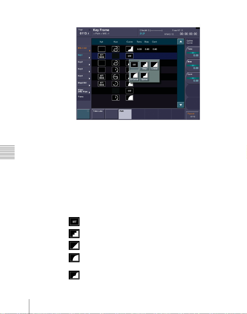
1
In the Path menu, press [M/E-1].
The M/E-1 menu appears.
2
Press the Curve path type indication for the Key1 item that you want to
change.
A path selection window appears.
3
Press the indication for the desired path type, to select it.
OFF: Executing the effect causes no change.
Step: There is no interpolation between keyframes, so that the
effect paramaters are updated each time a keyframe is passed.
Linear: Linear interpolation between keyframes, resulting in
constant speed movement.
S-Curve: The rate of change accelerates and decelerates before and
after a keyframe, so that the rate of change is maximum midway
between two keyframes.
Spline: The effect follows a smooth curved path from each
keyframe to the next.
38
Path Setting
Page 39
The status area reflects the selected path type.
At this point, depending on the setting for Curve, the effect for Hue and
Xpt is also affected as shown in the following table. In the menu, the Hue
and Xpt settings do not change, but the path t ype indication is di mmed out.
Curve setting Hue change Xpt change
OFF Does not change Hold
Step Changes as with the Step setting Is not affected
4
If you selected Spline as the path type, set the following parameters, using
the knobs.
Knob Parameter Adjustment Setting values
1 Tens Spline interpolation tension –4.00 to +4.00
2 Bias Spline interpolation bias –4.00 to +4.00
3 Cont Spline interpolation continuity –4.00 to +4.00
Changing the path type for Hue
1
Press the Hue path type indication for the item that you want to change.
2
Turn knob 1 to change the Hue path type.
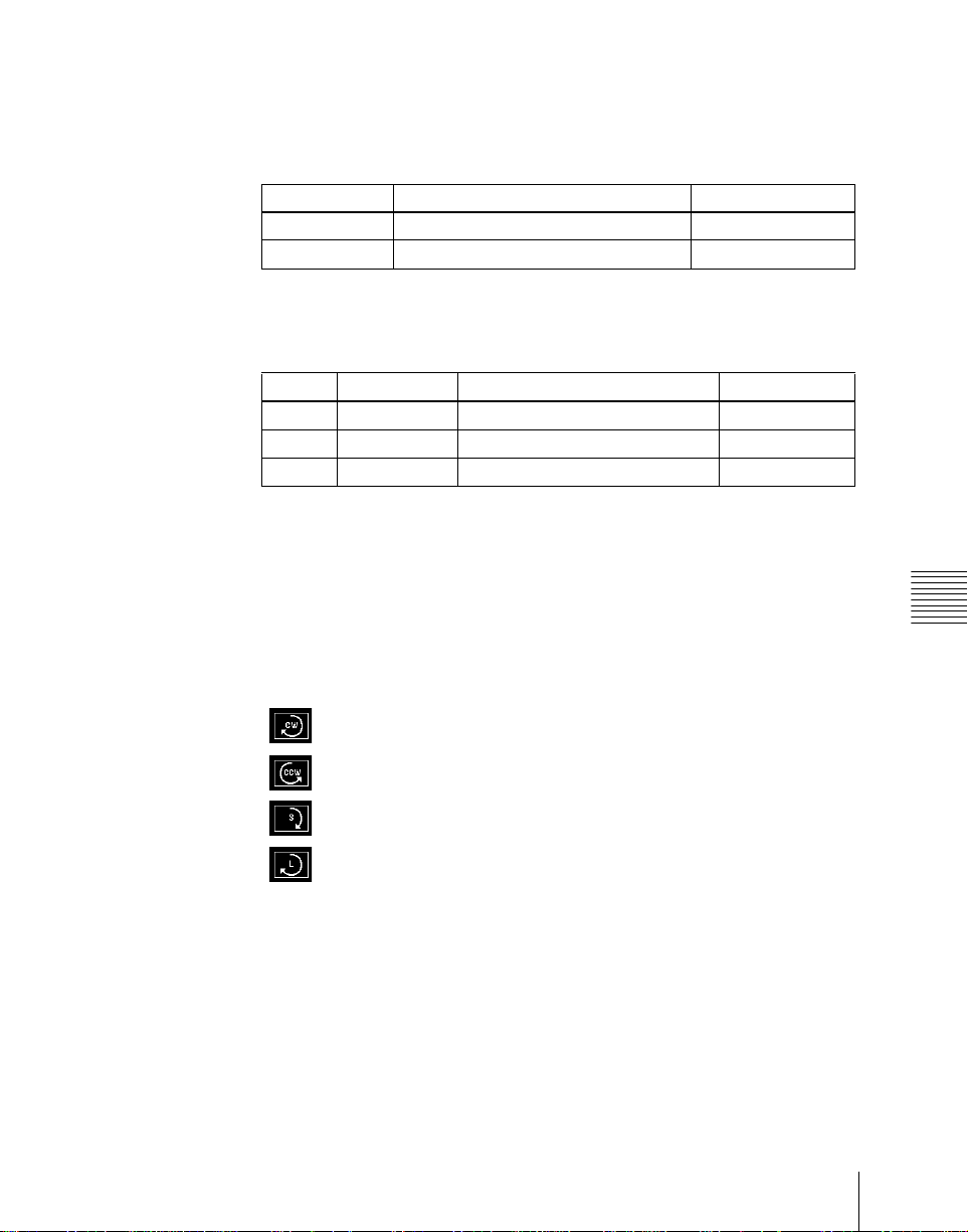
The path type indications shown in the menu represent the change in hue
as seen on a Vectorscope.
CW: Rotate clockwise.
CCW: Rotate counterclockwise.
Short: The hue changes in whichever of the clockwise and
counterclockwise directions is shorter.
Long: The hue changes in whichever of the clockwise and
counterclockwise directions is longer.
Changing the path type for Xpt
1
Press the Xpt path type indication for the item that you want to change.
A path selection window appears.
Chapter 13 Keyframe Effects
39Path Setting
Page 40

2
Press the indication for the desired path type, to select it.
Xpt Hold off: When replaying a keyframe, chang e the inputs to the
settings saved in memory.
Xpt Hold on: When replaying a keyframe, do not change the
inputs.
Chapter 13 Keyfra me Effects
40
Path Setting
Page 41
Executing Effects
By means of the [RUN] button in the keyframe control block, you can play an
effect as a continuously varying image. This is referred to as effect execution.
See also “Effect Execution” in Chapter 1 (Volume 1).
It is also possible to execute an effect from the device control block (see
Chapter 2 (Volume 1)).
Execution With the RUN Button (Auto Mode)
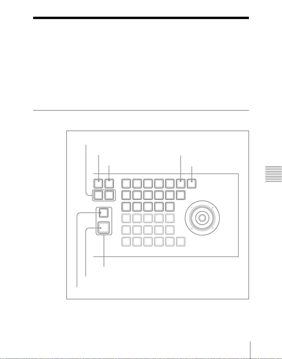
Effect execution direction selection buttons
EFF LOOP button
EFF
LOOP
NORM
/REV
Effect buttons
RUN button
REWIND button
STOP NEXT button
STOP
EDIT
NEXT
KF
RE
WIND
RUN
DUR
ENBL
COPY
PASTEREV
INS
MOD
LOCAL GLB SRC TRGT
MENU
ASP
AXIS
SKEW
LOC
PERS
CLR
SHIFT
WORK
BUFR
Keyframe control block
KF LOOP button
PAUSE button
EFF
KF
DUR
DEL
GOTO
KF/TC
LOC
SIZE
X
CONST
DELAY
DUR
FROMTORUN
UNDO
NEXT
PREV
KF
KF
LOC
ROT
XYZ
Y Z CTR
KF
PAUSE
LOOP
CTRL
Chapter 13 Keyframe Effects
41Executing Effects
Page 42

Executing an effect automatically
Use the following procedure.
1
Select the region in which you want to execute the effect, using the reg ion
selection buttons in the numeric keypad control block. (See step 2 (page
22) of “Recalling a register.”)
2
With the numeric keypad, enter the number of the register in which the
effect you want to execute is saved, and press the [ENTER] button to
confirm.
This recalls the effect saved in the register.
3
In the keyframe control block, press the [RUN] button.
The [RUN] button lights amber and the effect is executed automatically.
Moving to the first keyframe of the effect
To move to the first keyframe of the effect, press the [REWIND] button.
Run Mode Setting
Chapter 13 Keyfra me Effects
You can set the run mode in which an effect is executed when you press the
[RUN] button.
Specifying the effect execution direction
To specify the effect execution direction, press the [REV] button, turning it on
(REV) or off (NORM).
To execute the effect so as to alternate NORM and REV, press the [NORM/
REV] button, turning it on.
When the [REV] button is off: The effect is executed in the direction from
the first keyframe to the last keyframe.
When the [REV] button is on: The effect is executed in the d irection from the
last keyframe to the first keyframe.
When the [NORM/REV] button is on: Each time the effect is executed, the
direction reverses.
Executing an effect up to the next keyframe
Use the following procedure.
Executing Effects
42
Page 43

1
Press the [STOP NEXT KF] button, turning it on.
2
Press the [RUN] button.
This executes the effect as far as the next keyframe. When the [REV]
button is lit, it is executed as far as the previous keyframe.
Repeating an effect
Use the following procedure.
1
Press the [EFF LOOP] button, turning it on.
2
Press the [RUN] button.
This executes the effect repeatedly, from the first keyframe to the last
keyframe.
When the [REV] button is lit, the effect is executed in the reverse direction.
3
To stop the repeating effect, press the [EFF LOOP] button, turning it off,
or press the [REWIND] but t on.
Chapter 13 Keyframe Effects
43Executing Effects
Page 44

Saving Effects
When you recall an effect, the currently recalled effect is automatically saved
in a register. This is referred to as the auto save function.
You can disable the auto save function in a Setup menu.
By means of the following operation, you can also specify a register and save
an effect in it.
Saving an effect in a specified register
Specify the register using the numeric k eypad control b lock. Use the f ollowing
procedure.
1
Press the [EFF] button, turning it on.
This allocates the numeric keypad control block to keyframe operations.
2
Press the region sel ection button corresp onding to the regio n for which you
want to save the register, turning it on.
See step 2 (page 22) of “Recalling a register.”
Chapter 13 Keyfra me Effects
Saving Effects
44
3
Press the [STORE] button, turning it on.
4
With the numeric keypad, enter the number of the register in which you
want to save the effect.
To find an empty register, instead of entering a number, pres s the [.]
(period) button. To search for an empty register common to all currently
selectable regions, press the [.] button again.
To search for an empty register in the 100 range, press [1], [0], [0], [.]
(period) in this order. Similarly, to search for an empty register in the 200
range, press [2], [0], [0], [.] (period).
The register number appears in the displ ay. If the number is followed by a
letter ‘e’ or ‘E’, this indicates the following.
e: The selected register is empty for the regions selected in step 2.
E: The selected register is empty for all selectable regions.
5
Press the [ENTER] button.
This saves the current effect in the specified register, and turns off the
[STORE] button. The [RCALL] button and [STORE STATS] button both
light.
Page 45

To undo the saving of an effect
Immediately after saving an effect, hold down the [STORE STATS] button and
press the [UNDO] button to undo the save.
Chapter 13 Keyframe Effects
45Saving Effects
Page 46

Register Operations in the Menus
Using the Effect menu, you can carry out the following effect register
operations.
• Status display
• Register editing
To display the Effect menu
Press the top menu selection button [EFF] in the menu control block.
Effect Status Display
The Effect>Effect>Attribute menu displays the following information.
Region name: The selected region name appears in the upper part of the list.
Register number
Register name
Write-protected status: When the register is write-protected, an indication
“Lock” appears.
Chapter 13 Keyfra me Effects
Empty status: When the register is empty, the list is grayed out.
Effect Register Editing
You can carry out the following editing on effect registers.
• Lock: Write-protect the contents of the register.
• Copy: Copy the contents of one register to another register.
• Merge: Add the contents of the current reg ister to the end of th e contents of
another register.
•Move: Move the contents of one register to another register.
• Swap: Swap the contents of two registers.
• Delete: Delete the contents of a register.
• Name: Attach a name to a register.
For details of effect reg ister operation , see “Snapshot Register Editi ng” (page
58).
Note that the method of selection of registers is as follows.
All: Turn on to select all registers.
Block: When this is “ON,” you can select a co ntiguo us block of regi sters .
In this case, in the status area, press on a desired register number or
Register Operations in the Menus
46
Page 47
register name, to display it in reverse video. To cancel a selection,
press once more to return to the normal display.
Note
If you press a discontiguous register, this clears any previous
selection. Be very sure to select the registers to be contiguous.
When neither All nor Block is selected: You can use knob 1 to select a
single regi ster.
Knob Parameter Adjustment Setting values
1 Register Register number 1 to 399
Chapter 13 Keyframe Effects
47Register Operations in the Menus
Page 48

Chapter 13 Keyfra me Effects
Register Operations in the Menus
48
Page 49

Chapter 14 Snapshots
Snapshot Operations From the Numeric Keypad Control Block...... 50
Saving and Recalling Snapshots......................................................51
Snapshot Operations in the Menus....................................................... 55
Setting Snapshot Attributes.............................................................55
Snapshot Status Display .................................................................. 57
Setting Key Snapshot Attributes......................................................58
Snapshot Register Editing ......................................................... ......58
Page 50

Snapshot Operations From the Numeric
Keypad Control Block
The term “snapshot” refers to a f unction whereb y the various se ttings requi red
to apply a particular effect to an image are saved in memory as a set o f data, for
recall as required, to recover the original state.
For an overview of snapshots, see “Snapshots” in Chapter 1 (Volume 1).
Note
To use DME requires the BKDS-9470 DME Board Set.
You can carry out sn apshot operations using the numeri c keypad control block.
(See the following illustration.)
To apply attributes or disp lay the status, use the Snapshot men u. (See page 55.)
Chapter 14 Snapshots
Snapshot Operations From t he Numeric Keypad Control Block
50
Page 51
Saving and Recalling Snapshots
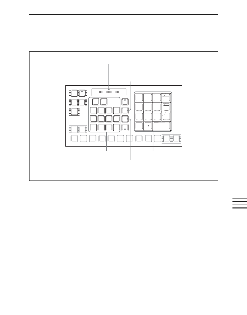
Snapshot operations with the numeric keypad control block use the following
buttons.
Display
UNDO button
SNAPSHOT button
SNAP
EFF
SHOT
SHOT
BOX
TRANS
RATE
M/E
1
AUX1AUX2AUX3AUX4AUX5AUX6AUX7FMS1FMS2EDIT
MCRO
P/P
MASTR ALL
M/E
USER1USER
P/P
1
DME1DME2DME3DME
GP1
P-BUS
STORE STATS button
UNDO
STORE
STATS
2
STORE
4
RCALL
7
4
5
2
1
0
DISS
CLR
AUTO
6
TRANS
TRIM
3
GPI
ENBL
ENTER
KEY SHIFT
PVW
+/-
EFF
9
8
Region selection buttons
Numeric keypad
STORE button
RCALL button
Numeric keypad control block
Saving a snapshot from the numeric keypad control block
Use the following procedure.
1
Make the settings for the state you want to save as a snapshot.
2
In the numeric keypad control block, press the [SNAPSHOT] button,
turning it on.
This allocates the numeric keypad control block to snapshot operations,
and the [RCALL] button lights.
Chapter 14 Snapshots
51Snapshot Operations From the Numeric Keypad Control Block
Page 52
3
Press the region sel ection button corresp onding to the regio n for which you
want to save, turning it on. You can select more than one region.
[M/E 1], [P/P]: These select the corresponding M/E-1, and PGM/PST
regions.
[USER 1] , [USER 2]: These select the USER regions.
[DME 1] to [DME 4]: These select DME channels.
[ALL]: This selects all regions.
The first button pressed lights green as the reference region, and any
subsequently pressed buttons light amber.
The display shows the name of the refer ence region, and the number of the
last register recalled for this region.
4
Press the [STORE] button, turning it on.
5
Enter the desired register number from the numeric keypad.
To find an empty register, instead of entering a number, press the period
(.) button. To search for an empty register common to all currently
selectable regions, press the period button again.
Note
If you choose a register which already contains a snapshot, and save a
snapshot, then the existing register contents are overwritten.
The register number appears in the displ ay. If the number is followed by a
letter ‘e’ or ‘E’, this indicates the following.
e: The selected register is empty for the regions selected in step 3.
E: The selected register is empty for all currently selectable regions.
The entered register number appears in the display.
6
To apply attributes, press the following buttons, turning them on.
Chapter 14 Snapshots
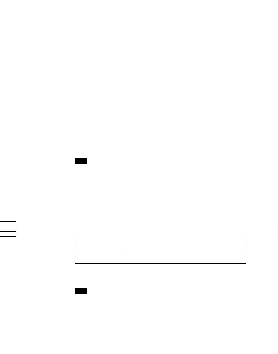
Attribute to apply Button
Effect dissolve [+/−/EFF DISS] button
Auto transition [CLR/AUTO TRANS] button
For details of attributes, see “Snapshots” in Chapter 1 (Volume 1).
Note
In the numeric keypad control block, it is not possible to apply the crosspoint hold and GPI output attributes. For these, see “Applying snapshot
attributes” (page 55).
Snapshot Operations From t he Numeric Keypad Control Block
52
Page 53

7
Press the [ENTER] button.
This saves the snapshot, and the [STORE] butt on goes off. The [RCALL]
and [STORE STATS] buttons light.
To cancel a snapshot save operation
After saving a snapshot, to cancel the save, hold down the [STORE STATS]
button and press the [UNDO] button.
Recalling a snapshot from the numeric keypad control block
Use the following procedure.
1
In the numeric keypad control block, press the [SNAPSHOT] button,
turning it on.
This allocates the numeric keypad control block to snapshot operations,
and the [RCALL] button lights.
2
Press the region sel ection button corresp onding to the regio n for which you
want to recall.
See step 3 (page 52) in “Saving a snapshot from the numeric keypad
control block.”
3
Enter the desired register number from the numeric keypad.
See step 5 (page 52) in “Saving a snapshot from the numeric keypad
control block.”
The entered register number appears in the display.
4
To set the A/B bus cross-point hold as a temporary attribute, press the
[XPT HOLD] button in the cross-point control block.
For details of temporar y attr ibutes , see “Sna pshot Attri butes” i n Cha pter
1 (Volume 1).
Notes
• The cross-point hold setting is maintained until you next press the [XPT
HOLD] button.
• Applying temporary attributes does not affect the contents of the
register.
Chapter 14 Snapshots
53Snapshot Operations From the Numeric Keypad Control Block
Page 54

5
Press the [ENTER] button.
This recalls the specified snapshot, and the reference region name and
recalled register number appear in the display.
If you applied the eff ect dis solve or auto transi tion tem porary attrib utes in
step 4, the corresponding buttons go off.
To cancel a snapshot recall operation
After saving a snapshot, to cancel the recall, press the [UNDO] button.
Chapter 14 Snapshots
Snapshot Operations From t he Numeric Keypad Control Block
54
Page 55

Snapshot Operations in the Menus
You can also set snapshot or key snapshot attributes in the Snapshot menu,
which also displays the status of the registers. To access the Snapshot menu,
press the top menu selection button [SNAPSHOT] in the menu control block.
In the Snapshot menu, as well as setting snapshot attributes, you can carry out
editing operations on snapshots, including copy and delete.
See “Snapshot Register Editing” (page 58).
Setting Snapshot Attributes
Applying snapshot attributes
To apply an attribute to a snapshot, use the following procedure.
1
In the Snapshot menu, press VF2 ‘Snapshot’ and HF1 ‘Attribute.’
The Snapshot>Attribute menu appears.
The status area shows the region names, register numbers, and the status
and attributes set.
2
Press the region display in the upper part of the list to disp lay a selection
window, then select the region in the selection window.
The selected region name appears in the upper part of the list.
3
To select the desired register, press the register n umber or register name in
the status area, or turn knob 1.
Knob Parameter Adjustment Setting values
1 Register Register number 1 to 99
4
In the <Attribute> group, press the buttons for the attributes you want to
apply, turning them on.
Carry out the following procedures for each of the attributes.
Chapter 14 Snapshots
55Snapshot Operations in the Menus
Page 56
To apply the cross-point hold attributes
1
Press [Xpt Hold], turning it on.
The Snapshot>Attribute>Xpt Hold menu appears. The status area shows a
list of the currently selected regions and bus names.
2
To select the desired register, press the register n umber or register name in
the status area, or turn knob 2.
Knob Parameter Adjustment Setting values
2 Bus Bus name selection –
3
Press [On].
This enables cross-point hold on the selected bus or buses.
To switch cross-point hold off, press [Off].
To apply the effect dissolve attribute
1
Press [Effect Dissolve], turning it on.
2
Turn knob 2 to set the effect dissolve duration.
Knob Parameter Adjustment Setting values
2 Duration Dissolve durat ion 0 to 999 (frames)
To apply the auto transition attribute
Press [Auto Transition], turning it on.
To apply the GPI output attribute
1
Chapter 14 Snapshots
Snapshot Operations in the Menus
56
Press [GPI Output], turning it on.
2
Turn knob 2 to set the port number.
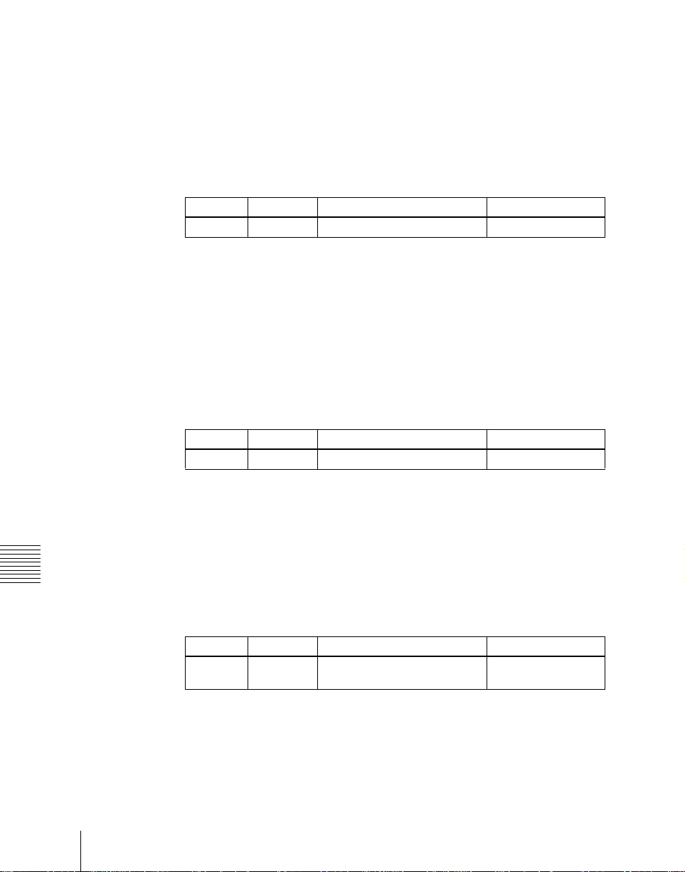
Knob Parameter Adjustment Setting values
2 GPI Out
Port
For details of attributes, see “Snapshots” in Chapter 1 (Volume 1).
GPI output port number 1 to 8
Page 57
Snapshot Status Display
The Snapshot>Attribute menu displays the following information.
For details of how to access the Snapshot>Attribute menu, see page 55.
Region name: The selected region name appears in the upper part of the list.
Register number
Register name
Write-protected status: When the register is write-protected, an “L” (for
“lock”) appears.
Empty status: When the register is empty, an “E” (for “empty”) appears.
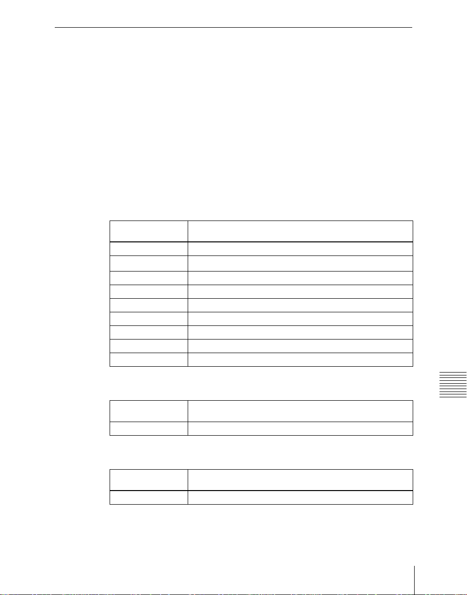
Attribute settings: The attributes set for a register are shown by the following
character codes.
When the cross-point hold is set:
Displayed
character codes
A, B Cross-point hold is set for the A or B background bus.
1, 2, 3, 4
U1, U2 Cross-point hold is set for the utility 1 or utility 2 bus.
Fv Cross-point hold is set for the DME front video bus.
Fk Cross-point hold is set for the DME front key bus.
Bv Cross-point hold is set for the DME back video bus.
Bk Cross-point hold is set for the DME back key bus.
Aux Cross-point hold is set for one of the AUX buses.
RTR Cross-point hold is set for the Router region.
Attributes set
Cross-point hold is set for key bus 1, 2, 3, or 4.
When an effect dissolve is set:
Displayed
character codes
Duration value The effect dissolve attribute is set, with the displayed duration.
Attributes set
When an auto transition is set:
Displayed
character codes
T Auto transition is set.
Attributes set
Chapter 14 Snapshots
57Snapshot Operations in the Menus
Page 58
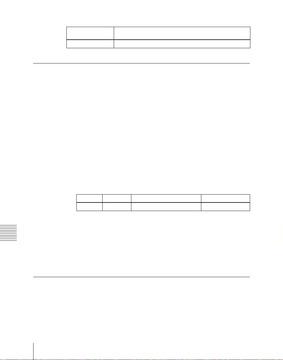
When a GPI output is set:
Displayed
character codes
Port number GPI output is set for the port of the displayed number.
Attributes set
Setting Key Snapshot Attributes
Applying key snapshot attributes
To apply an attribute to a key snapshot, use the following procedure.
1
In the Snapshot menu, press VF5 ‘Key Snapshot’ and HF1 ‘Attribute.’
The Snapshot>Key Snapshot>Attribute menu appears.
The status area shows the region names, register numbers, and whether the
registers are locked or not.
2
Press the region display in the upper part of the list to disp lay a selection
window, then select the region in the selection window.
The selected region name appears in the upper part of the list.
3
To select the desired register, pr ess on the register number or register name
in the status area, or use knob 1.
Knob Parameter Adjustment Setting values
1 Register Register number 1 to 99
4
In the <Recall Mode> group, select one of the following modes for save
and recall operations.
Chapter 14 Snapshots
XPT: Only the key material selection data is saved or recalled.
Modifier: Only the key modifier settings are saved or recalled.
Transition: Only the independent key transition settings are saved or
recalled.
Snapshot Register Editing
You can carry out the following editing on snapshot registers.
(You can use similar procedures also on wipe snapshot, DME wipe snapshot
and key snapshot registers.)
• Lock: Write-protect the contents of the register.
Snapshot Operations in the Menus
58
Page 59
• Copy: Copy the contents of one register to another register.
•Move: Move the contents of one register to another register.
• Swap: Swap the contents of two registers.
• Delete: Delete the contents of a register.
• Name: Attach a name to a register.
Write-protecting the contents of the snapshot register
Use the following procedure.
Note
It is not possible to write-protect an empty register.
1
In the Snapshot menu, press VF2 ‘Snapshot’ and HF2 ‘Lock.’
The Snapshot>Snapshot>Lock menu appears.
2
Press the region display in the upper part of the list to disp lay a selection
window, then select the region in the selection window.
The selected region name appears in the upper part of the list.
3
To select the desired register, pr ess on the register number or register name
in the status area, or use knob 1.
Knob Parameter Adjustment Setting values
1 Register Register number
1 to 99
4
Press [Lock], write-protecting the register.
Copying, moving, and swapping snapshot register data
This section describes the procedure for copying. You can move or swap
registers using a similar procedure.
1
In the Snapshot menu, press VF2 ‘Snapshot’ and HF3 ‘Copy.’
• The Snapshot>Snapshot>Copy menu appears.
• The left side of the statu s area shows the snapshot r egister number o f the
copy source, and the right s ide shows the snapshot r egister number of the
copy destination.
2
Press the region display in the upper part of the list to disp lay a selection
window, then select the region in the selection window.
The selected region name appears in the upper part of the list.
Chapter 14 Snapshots
59Snapshot Operations in the Menus
Page 60
Operation between regions
Operation between regions is possible in the following cases.
• Between the M/E-1 and P/P regions
• Between the USER1 and USER2 regions
• Betweeen two of the DME1 to DME4 (including Global) regions
3
To select the desired registers, press on the register numbers or register
names in the status area, or use the knobs.
Knob Parameter Adjustment Setting values
1 From Reg Copy source register number 1 to 99
2 To Reg Copy destination register number 1 to 99
4
To copy without transferring the name, press [W/o Name], turning it on.
5
Press [Copy].
This carries out the copy.
If, for example, the copy destination register is write-protected or the same
register is specified both as the copy source and destination registers, a
confirmation message appears. Press [OK] to cancel the copy.
Deleting data from snapshot registers
Use the following procedure.
1
In the Snapshot menu, press VF2 ‘Snapshot’ and HF6 ‘Delete.’
The Snapshot>Snapshot>Delete menu appears.
2
Press the region display in the upper part of the list to disp lay a selection
window, then select the region in the selection window.
Chapter 14 Snapshots
The selected region name appears in the upper part of the list.
3
To select the desired register, pr ess on the register number or register name
in the status area, or use knob 1.
Knob Parameter Adjustment Setting values
1 Register Register number
4
Press [Delete].
1 to 99
Attaching a name to a snapshot regis ter
Use the following procedure.
Snapshot Operations in the Menus
60
Page 61
1
In the Snapshot menu, press VF2 ‘Snapshot’ and HF7 ‘Rename.’
The Snapshot>Snapshot>Rename menu appears.
2
Using any of the fo llowin g met hods, sel ect th e snap shot r egist er y ou w ant
to name.
• Press the desired register name in the register list.
• Press the arrow keys to scroll the reverse video cursor.
• Turn knob 1 to select a register.
Knob Parameter Adjustment Setting values
1 Register Register number 1 to 99
The selected register appears in reverse video.
3
Press [Rename].
A keyboard window appears.
For details of keyboard window operation, see “Menu Operations” in
Chapter 2 (Volume 1).
4
Enter the name, of not more than eight characters, and press [Enter].
The set name appears in reverse video in the status area.
Chapter 14 Snapshots
61Snapshot Operations in the Menus
Page 62

Chapter 14 Snapshots
Snapshot Operations in the Menus
62
Page 63

Chapter 15 Shot Box
Shot Box Register Creation....................................................................64
Shot Box Execution.................................................................................67
Shot Box Execution From the Numeric Keypad Control Block.....67
Shot Box Execution in the Utility/Shot Box Control Block............69
Shot Box Register Editing......................................................................71
Page 64

Shot Box Register Creation
The term “shot box” refers to a function whereby for each specified region any
snapshot or keyframe effect can be recalled simultaneously. For each region,
Chapter 15 Shot Box
Accessing the Shotbox menu
Creating a shot box register
any snapshot or keyframe effect number can be specified to be recalled.
There is also a setting to enable or disable the auto run function.
For a shot box overview, see “Shot Box ” in Chapter 1 (Volume 1).
Carry out creation and editing of shot box registers in the Shotbox menu.
To access the Shotbox menu, use the following method.
• In the menu control block, press the top menu selection button [SHOT
BOX].
Use the following procedure.
1
In the Shotbox menu, press VF1 ‘Register’ and HF1 ‘Store/Recall.’
The Shotbox>Register>Store/Recall menu appears.
In the status area, the settings for each register appear as follows.
Region settings: Appear as “Sxxx” when a snapshot is allocated, and as
“Exxx” when an effect is allocated. (xxx is the register number.) The
register name also appears. If nothing is allocated, nothing appears in
the display.
Register lock setting: When the register is write-protected, an “L”
appears.
Auto run setting: W hen this is enabled, so that an effect is executed
simultaneously with recall, “AR” appears.
Shot box register name: This shows the shot box register name.
Shot Box Regis ter Creation
64
2
To switch the status area region display, press one of the [Switcher],
[DME], [Misc] indications that appear in the status area.
Switcher: Shows the allocations for M/E-1 (“ME1”), P/P (“PP”), User1
(“USR1”), and User2 (“USR2”).
DME: Shows the allocations for DME channel 1 (“DME1”), channel 2
(“DME2”), channel 3 (“DME3”), and channel 4 (“DME4”).
Misc: Shows the allocations for P-BUS (“PBUS”), GPI (“GPI”), Router
(“RTR”), Device1 (“DEV1”), and Device2 (“DEV2”).
Page 65
3
Using any of the following methods, select the register you want to create
(or edit).
• In the status area, press the [No] or [Name] for the shot box register you
want to select, then press [EDIT].
• Use knob 1 to specify the register, and press [Edit].
Knob Parameter Adjustment Setting values
1 Shotbox Reg Shot bo x register number 1 to 99
The Shotbox>Register>Store/Recall>Edit menu appears, and it is now
possible to make the settings for the specified register.
You can also use knob 1 to select the register in this menu.
In the status area, the shot box register status for each region appears.
4
To select th e desired region, press on the region name in the status area.
5
In the <Assign> group, select the snapshot or effect to be allocated to the
region.
[Snapshot]: Allocate a snapshot register.
[Effect]: Allocate a keyframe effect.
6
Depending on the selection in step 5, set the parameters as follows.
• When a snapshot is selected
Knob Parameter Adjustment Setting values
2 Snapshot Snapshot register number 1 to 99
• When an effect is selected
Knob Parameter Adjustment Setting values
2 Effect Keyframe effect number
1 to 99
a)
Chapter 15 Shot Box
a) For the DME region, you can also set register numbers 101 to 199, 201 to 299, and 301 to
399.
7
To run the allocated effect as soon as it is recalled, press [Auto Run],
turning it on.
8
Repeat steps 4 to 7 as required.
9
In the <Store> group, press [Store], to save the setting.
Note
“GPI” and “Router” are not executed even if set.
65Shot Box Register Creation
Page 66

To return to the state before saving the setting
In the <Store> group, press [Undo].
To run the settings to check them
In the <Recall> group, press [Recall], to run the shot box.
Chapter 15 Shot Box
Shot Box Regis ter Creation
66
Page 67
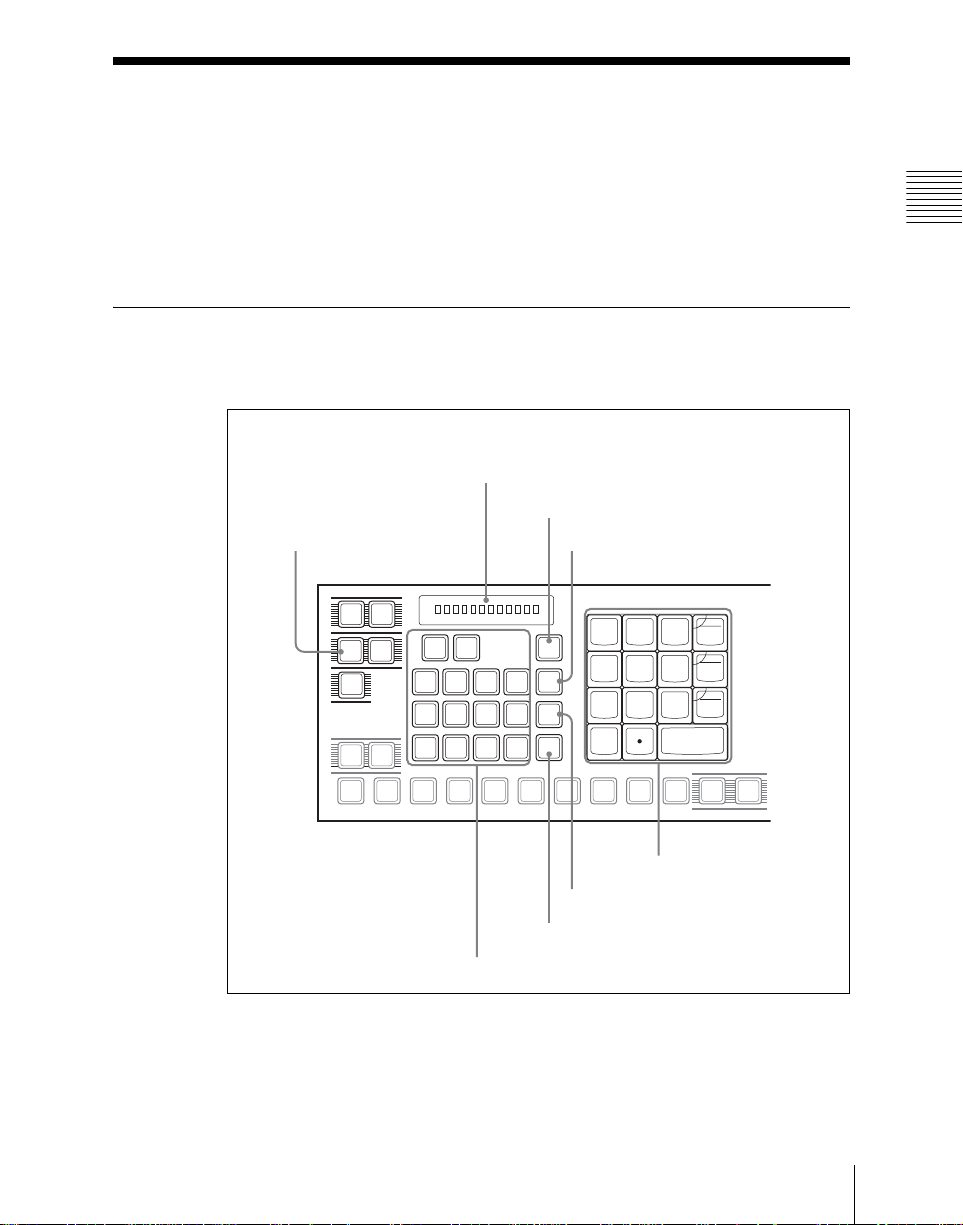
Shot Box Execution
You can recall (and run) shot box registers from the following control blocks.
This section describes the various methods of operation.
• Numeric keypad control block (see page 67)
• Utility/shot box control block (see page 69)
Shot Box Execution From the Numeric Keypad Contr ol
Block
Display
UNDO butto n
Chapter 15 Shot Box
SHOT BOX button
SNAP
EFF
SHOT
SHOT
MCRO
BOX
TRANS
RATE
M/E
P/P
1
AUX1AUX2AUX3AUX4AUX5AUX6AUX7FMS1FMS2EDIT
MASTR ALL
M/E
USER1USER
P/P
1
DME1DME2DME3DME
GP1
P-BUS
STORE STATS button
UNDO
STORE
STATS
2
STORE
4
RCALL
7
4
1
0
8
5
2
DISS
CLR
AUTO
6
TRANS
TRIM
3
GPI
ENBL
ENTER
KEY SHIFT
PVW
+/-
EFF
9
Numeric keypad
STORE button
RCALL button
Region selection buttons
Numeric keypad control block
To carry out shot box execution in the numeric keypad control block, use the
following procedure.
67Shot Box Execu tion
Page 68

1
In the numeric keypad control block, press the [SHOT BOX] button,
turning it on.
• This allocates the numeric keypad control block to shot box operations.
• The [RCALL] button lights amber.
• The display shows the last recalled register number.
2
Chapter 15 Shot Box
With the numeric keypad buttons, enter the desired register number.
• The display now shows the entered register number.
• If the specified register is empty, an “E” automatically appears after the
register number.
3
Press the [ENTER] button.
• This runs the specified shot box register.
• The number of the recalled register appears in the display.
• The region selection buttons corres pondi ng to the r egions fo r which t he
effect is set light.
• If auto run is set for the specified shot box register, on recall the effect is
immediately executed.
• If you recall an empty register, then shot box execution has no effect.
When auto run is not set for the recalled register
Simply recalling the register does not run the effect. To do this, in the
keyframe control block, press the [RUN] button.
Shot Box Execution
68
Page 69
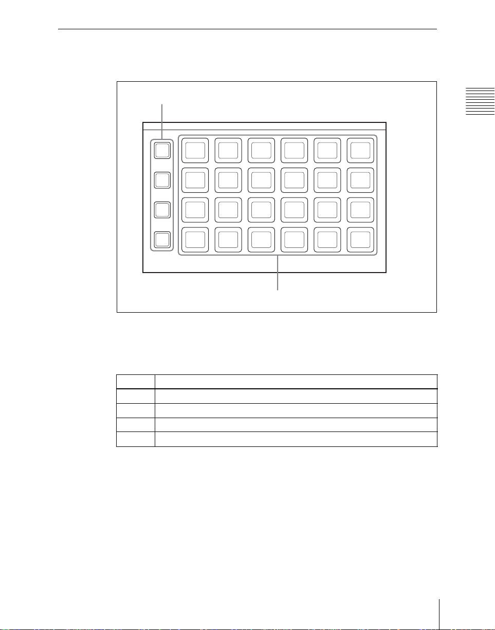
Shot Box Execution in the Utility/Shot Box Contro l
Block
Bank selection buttons
Chapter 15 Shot Box
BANK
BANK
BANK
BANK
1
2
3
4
1
7
13 14 15 16 17 18
19 20 21 22 23 24
2 3 4
89101112
56
Memory recall buttons
Utility/shot box control block (MKS-8033)
In the utility/shot box control block, as the default setting the memory recall
buttons have registers 1 to 96 allocated to banks 1 to 4.
Bank Register allocation to memory recall buttons
11 to 24
2 25 to 48
3 49 to 72
4 73 to 96
For shot box execution in the utility/shot box control block, use the following
procedure.
1
Press one of the bank selection buttons [BANK1] to [BANK4] to select the
bank.
• The pressed bank selection button lights amber.
• The memory recall buttons show the names and states of the registers
corresponding to the selected bank.
69Shot Box Execu tion
Page 70

Off: Register in which nothing is saved
Lit orange: Register holding shot box settings
Lit yellow: Last recalled register
2
Press the memory recall button to which t he shot bo x regist er you wa nt to
run is allocated.
Chapter 15 Shot Box
• The shot box execution is carried out.
• The pressed button lights yellow.
• The numeric keypad control block [SHOT BOX] button lights, and the
region selection button corresponding to the reg ion f or which th e eff ect
is set also lights.
• If the selected shot box register has auto run set, on recall the effect is
immediately executed.
When auto run is not set for the recalled register
Simply recalling the register does not run the effect. To do this, press the
[RUN] button in the keyframe control block.
Shot Box Execution
70
Page 71

Shot Box Register Editing
You can carry out the following editing on shot box registers.
• Lock: Write-protect the contents of the register.
• Copy: Copy data from one register to another.
• Move: Move data from one register to another.
• Swap: Swap the contents of two registers.
• Delete: Delete the contents of a register.
• Name: Attach a name to a register.
The procedures for shot box register editing are similar to the procedures
described in “Snapshot Register Editing” (see page 58). Unlike in effect
register editing, however, it is not necessary to specify a region in shot box
register editing. When copying, moving or swapping data between shot box
registers, select the source and destination r egisters u sing one of the f ollowing
methods.
• Set the following parameters.
Knob P arameter Adjustment Setting values
1 From Reg Shot box register number of copy source 1 to 99
2 To Reg Shot box register number of copy
destination
• In the status area select the shot box regist ers for which you want to make the
setting.
To cancel the selection: Press the selected shot box register again, r everting
it to normal display.
Chapter 15 Shot Box
1 to 99
71Shot Box Register Editing
Page 72

Chapter 15 Shot Box
Shot Box Register Editing
72
Page 73

Chapter 16 Engineering Setup
Setup for the Whole System...................................................................75
Network Settings (Network Config Menu).....................................75
System Settings (System Config Menu).......................................... 76
Setting the Signal Format and Screen Aspect Ratio
(Format Menu) .....................................................................78
Selecting the State After Powering On (Start Up Menu) ................ 79
Reset and Initialization (Initialize Menu)........................................81
Installation (Install Menu)............................................................... 82
System Maintenance (Maintenance Menu).....................................82
Setup Relating to Operations From the Control Panel....................... 85
Overall Control Panel Settings (Config Menu)...............................85
Cross-Point Settings (Xpt Assign Menu)........................................90
AUX Delegation Buttons Settings (Aux Assign Menu)..................94
Interfacing With External Devices (Device Interface Menu)..........95
Operation Settings (Operation Menu) .............................................99
Screen Saver and Other Settings (Maintenance Menu)................. 101
Setup Relating to Switcher Processor.................................................103
Settings for Switcher Configuration (Config Menu).....................103
Signal Input Settings (Input Menu)...............................................106
Signal Output Settings (Output Menu)..........................................107
Settings Relating to Video Switching (Transition Menu)............. 110
Settings Relating to Keys, Wipes and Frame Memory
(Key/Wipe/FM Menu)........................................................ 112
Settings Relating to Function Links (Link Menu).........................114
Interfacing With External Devices (Device Interface Menu)........118
Setup Relating to DME ........................................................................123
Settings Relating to Signal Inputs (Input Menu)........................... 123
Interfacing With External Devices (Device Interface Menu)........124
Page 74

Setup Relating to DCU.........................................................................127
Settings Relating to Signal Inputs (Input Config Menu)............... 127
GPI Input Setting (GPI Input Assign Menu)................................. 128
Signal Output Settings (Output Config Menu)..............................130
GPI Output Setting (GPI Output Assign Menu)............................132
Setup Relating to Router Interface and Tally....................................134
Router Interface Settings (Router Menu)......................................134
Tally Group Settings (Group Tally Menu).................................... 136
Wiring Settings (Wiring Menu).....................................................137
Tally Generation Settings (Tally Enable Menu)............................ 139
Tally Copy Settings (Tally Copy Menu).......................................140
Parallel Tally Settings (Parallel Tally Menu)................................142
Simple Connection of the MKS-8080/8082 AUX Bus Remote
Panel ...........................................................................................145
Procedure for Simple Connection..................................................145
Setting Status of the MKS-8080/8082 in Simple Connection....... 146
Page 75
Setup for the Whole System
Carry out operations relating to setup in the Engineering Setup menu.
To access the Engineering Setup menu, press the top menu selection button
[ENG SETUP].
For an overview of setup, see “Setup” in Chapter 1 (Volume 1).
Setting the unit ID
When there are two switchers and connected DME units on the same network,
it is necessary to set the unit ID on each device, as follows.
Device ID
1st switcher 1
2nd switcher 2
Device ID
DME1 for 1st switcher (channels 1 to 4)
DME2 for 1st switcher (channels 5 to 8)
DME1 for 2nd switcher (channels 1 to 4)
DME2 for 2nd switcher (channels 5 to 8)
a) The DME2 is not connectable in the MV S - 8000SF system.
1
a) 2
3
a) 4
For more details of how to make the device ID settings, refer to the installation
manual for the particular device.
Network Settings (Network Config Menu)
To display the Network Config menu
In the Engineering Setup menu, select VF1 ‘System’ and HF1 ‘Network
Config.’
The status area shows the device ID, and Control LAN, Data LAN and
Peripheral LAN IP addresses for each device.
Chapter 16 Engineering Setup
Making the network settings
Use the following procedure.
75Setup for the Whole System
Page 76

1
In the System>Network Config menu, press [Auto Config].
2
Turn the MKS-8010 System Control Unit off, then on again to restart the
unit.
This automatically checks all devices (excluding the DCU) connected to
the Data LAN, and shows the results in the status area of the
System>Network Config menu.
Note
Be sure to carry out this operation after reconfiguring the system, or after a
software upgrade.
Chapter 16 Engineering Setup
System Settings (System Config Menu)
To make the system settings, use the System>System Config menu.
To display the System Config menu
In the Engineering Setup menu, select VF1 ‘System’ and HF2 ‘System
Config.’
Note
After changing any of the following settings, be sure to press [Execute] to save
the new values. If you want to cancel the setting changes without saving them,
press [Clear].
Selecting the system operation mode
In the <System Operation Mode> g rou p of the System>System Conf ig menu,
select one of the following.
Single Proc: Control mode in which the panel controls a switcher and up to
two DMEs connected to the switcher.
Dual Simul: Control mode in which the panel controls two switch e r s an d the
DME connected to each switcher simultaneously.
Specifying the switcher controlled by the control panel
Use the following procedure.
Setup for the Wh ol e System
76
1
In the System>System Config menu, press the [Panel Assign] button.
The Panel Assign menu appears.
Page 77

2
Select the switcher to be controlled by the selected control panel, as
follows.
• If there is only one switcher on the network, in the <1st Switcher>
group, set [SWR1] to ON, and in the <2nd Switcher> gr oup, set [SWR2]
to OFF.
• If there are two switchers on the same network, in the <1st Switcher>
group, select the switcher to be operated.
3
To enable the router/tally interface on the selected control panel, press
[Router/Tally], turning it on.
Specifying the DME connected to the switcher
Use the following procedure.
1
In the System>System Config menu, press [Switcher Assign].
The Switcher Assign menu appears.
2
Using either of the following methods, select the switcher to which the
settings apply.
• In the list appearing in the menu, press the desired device name.
• Press the arrow keys to scroll the reverse video cursor.
The selected switcher appears in reverse video.
If there is only one switcher on the network, carry out the SWR1 setting
(for the first switcher) only.
Chapter 16 Engineering Setup
3
Make the DME settings as follows.
• When making DME settings for SWR1 (the first switcher), select
[DME1] in the <1st DME> group. Turn all buttons in the <2nd DME>
group off.
• When making DME settings for SWR2 (the second switcher), select
[DME3] in the <1st DME> group. Turn all buttons in the <2nd DME>
group off.
Note
To use DME requires the BKDS-9470 DME Board Set.
Setup in “Dual Simul” mode
When the system operating mode (see page 76) is set to “Dual Simul,” the
following setting is required for setup of t he two switchers and connect ed DME
units.
77Setup for the Whole System
Page 78

In the <Setup Target> group, set the [System 1] or [System 2] button to ON,
then carry out the setup. You can also set both to ON, and make the settings
simultaneously on the two systems.
Setting the Signal Format and Screen Aspect Ratio
(Format Menu)
To set the format, that is, the frame frequency and nu mber of scan lines handled
by each device, and the screen aspect ratio, use the System>Format menu.
To display the Format menu
In the Engineering Setup menu, select VF1 ‘System’ and HF3 ‘Format.’
Chapter 16 Engineering Setup
Note
After changing any of the following settings, be sure to press [Execute] to save
the new values. If you want to cancel the setting changes without saving them,
press [Clear].
Note that since the [Execute] button is in the System>Format menu, when you
make settings in a submenu, it is essential to remember to return to the
System>Format menu and press the [Execute] button to save.
Setting the signal format
Use the following procedure.
1
In the <Frame/Field Rate> group of the System>Format menu, select the
system operating frequency.
For more details, see “System Setup” in Chapter 1 (Volume 1).
2
Press the [Active Line/Aspect].
The Active Line/Aspect menu appears.
The status area shows the number of active scan lines and screen aspect
ratio for the switcher and connected DME.
3
In the <Active Line> group, select the number of active scan lines.
Setting the screen aspect ratio
Use the following procedure.
Setup for the Wh ol e System
78
Page 79

1
In the System>Format>Active Line/Aspect menu, select one of the
following from the <Screen Aspect> group.
• 16:9
•4:3
• Independ
Set the screen aspect ratio separately for M/E, P/P, and USER on the
switcher, and for each channel independently on the DME.
2
If you selected [Independ] in step 1, select from the following.
Switcher Aspect: Make the setting for the switcher.
DME Aspect: Make the setting for the DME.
A menu appears according to the selection.
3
Carry out either of the fo llo win g, d epen di ng on th e s el ectio n y ou made i n
step 2.
When you selected [Switcher Aspect]: In each of the <M/E-1>, <M/E-
2>, <M/E-3>, <P/P>, and <USER> groups, select either [16:9] or
[4:3].
When you selected [DME Aspect]: For each of the <CH1> to <CH4>
groups, sel ect either [16:9] or [4:3].
Chapter 16 Engineering Setup
Selecting the State After Powering On (Start Up Menu)
To set the initial state at start-up, use the System>Start Up menu.
Note
It is not possible to set the DCU state at start-up, but its settings can be saved
in the control panel.
To display the Start Up menu
In the Engineering Setup menu, select VF1 ‘System’ and HF4 ‘Start Up.’
The status area shows the current start-up mode settings.
Selecting the state at start-up
Use the following procedure.
1
In the status area of the System>Start Up menu, select the device to which
the settings are to apply.
79Setup for the Whole System
Page 80

2
In the <Start Up Mode> group, sel ect one of the following modes.
Resume: When this is on, Resume mode is enabled.
Custom: When this is on, Custom mode is enabled.
For information about Resume mode and Custom mode, see “System
Setup” in Chapter 1 (Volume 1).
Note
The Resume mode is only valid when a switcher or control panel is
selected for the setting.
3
When Custom mode is selected, in each of the <Setup> group and <Initial
Status> group, select one of the following.
User: When this is on, user-defined settings are used for the Setup or
Chapter 16 Engineering Setup
4
5
Initial Status settings. For the method of saving the user-defined
settings, see the next item.
Factory: When this is on, factory default settings are used for the Setup or
Initial Status settings.
To confirm the settings, press [Execute]. If you want to cancel the setting
changes without saving them, press [Clear].
When [Execute] is pressed, a confirmation message appears.
Select [Yes].
The start-up state settings are saved.
Saving user-defined settings
To save the Setup settings
Use the following procedure.
1
After selecting the devices the settings apply to, in the System>Start Up
menu, press [Setup Define].
A confirmation message appears.
2
Press [Yes].
This saves the setup settings for the selected devices in non-volatile
memory within the respective devices.
To save the Initial Status settings
Use the following procedure.
Setup for the Wh ol e System
80
Page 81

1
After selecting the devices the settings apply to, in the System>Start Up
menu, press [Initial Status Define].
A confirmation message appears.
2
Press [Yes].
This saves the initial status settings other than the “setup” settings for the
selected devices in non-volatile memory within the respective devices.
Reset and Initialization (Initialize Menu)
To carry out a reset or memory initialization for a device, use the
System>Initialize menu.
To display the Initialize menu
In the Engineering Setup menu, select VF1 ‘System’ and HF5 ‘Initialize.’
The status area shows the current start-up mode settings.
Resetting the device and initialize memory
Use the following procedure.
1
In the status area of the System>Initialize menu, select the device to which
the settings are to apply.
Chapter 16 Engineering Setup
2
In the <Initialize> group, select one of the following modes.
Reset: Reset the device.
All Clear: Initialize memory.
3
Press [Execute].
A confirmation message appears.
4
Select [Yes].
Depending on the selection in step 2, the following is the result.
• When you selected [Reset], a reset is applied to the device causing it to
be restarted in the start-up state.
• When you selected [All Clear], all memory in the device is cleared,
including snapshots, keyframe effects, setup, and so on, and the device
returns to its factory default settings. However, the Network Config,
Format, Start Up, and Date/Time settings are not initialized.
81Setup for the Whole System
Page 82

Installation (Install Menu)
To install software or firmware in a device, use the System>Install menu.
To display the Install menu
In the Engineering Setup menu, select VF1 ‘System’ and HF6 ‘Install.’
The status area shows the device ID of each device and the version of the
installed software.
Installing software
Use the following procedure.
1
Insert the memory card holding the software into the memory card slot.
Chapter 16 Engineering Setup
2
Press the [Install] button.
A list of the software contained in the memory card appears.
3
In the status area of the System> Install menu, select the device type.
4
To carry out installation, press [Execute].
A confirmation message appears.
5
Select [Yes].
This carries out a standard configuration installation.
Displaying installation details
In the System>Install menu, press [Detail Information].
This accesses the Detail Information menu, and displays the detailed
information on the software and firmware installed in the currently selected
device.
System Maintenance (Maintenance Menu)
To carry out system date and time settings, and memory card formatting, use
the System>Maintenance menu.
Setup for the Wh ol e System
82
Page 83
To display the Maintenance menu
In the Engineering Setup menu, select VF1 ‘System’ and HF7 ‘Maintenance.’
In the status area, the current date and time, and details of the memory card
appear.
Setting the date and time
For system date and time settings, use the following procedure.
1
With the knobs, adjust the following parameters.
Knob Parameter Adjustment Setting values
1 Hour Hour 0 to 23
2 Min Minute 0 to 59
3 Sec Secon d 0 to 59
6 Month Month 1 to 12
7 Day Day 1 to 31
8 Year Year 2000 to 2037
The set date and time appears in the “Set” box in the status area.
2
Press the [Set Date/Time] button.
This sets the current time to the date and time set in step 1, and the setting
in the “Current” box of the status area changes accordingly.
Chapter 16 Engineering Setup
Formatting a memory card
To format a memory card, use the following procedure.
1
Insert the memory card in the memory card slot.
2
In the System>Maintenance menu, using any of the following methods,
select the USB device.
• Press directly on the list appearing in the status area.
• Press the arrow keys to scroll the reverse video cursor.
3
In the <USB Storage Device> group, press [Format].
A confirmation message appears.
4
To carry out the formatting, press [OK].
This formats the memory card.
83Setup for the Whole System
Page 84

Carrying out the primary setting
To make the primary specification for a USB device, use the following
procedure.
1
In the System>Maintenance menu, using any of the following methods,
select the USB device you want to set as primary.
• Press directly on the list appearing in the status area.
• Press the arrow keys to scroll the reverse video cursor.
2
In the <USB Storage Device> group, press [Set Primary].
Chapter 16 Engineering Setup
Setup for the Wh ol e System
84
Page 85
Setup Relating to Operations From the
Control Panel
Overall Control Panel Settings (Config Menu)
To carry out the overall control panel settings, use the Panel>Config menu.
To display the Config menu
In the Engineering Setup menu, select VF2 ‘Panel’ and HF1 ‘Config.’
The status area shows the “Bank numbers 1 to 4” (physical locations) of the
operating banks, the allocated operating bank names, and whether or not
operation is enabled.
Interchanging the operating bank order or disable operation
Use the following procedure.
1
In the Panel>Config menu, select the Bank you want to set , using either of
the following methods.
• Press directly on the status area display.
• Press the arrow keys to scroll the reverse video cursor.
• Turn knob 1 to make the setting.
Chapter 16 Engineering Setup
Knob Parameter Ad j ustm ent Setting values
1 Bank Select the position of the operating bank
The Bank selection here indicates the physical position on the control
panel, numbering from the top as the 1st Ro w, 2nd Row, 3rd Row, and 4th
Row.
In the MKS-9011 1 M/E Control Panel, only the 1st Row is available. In
the MKS-9012 2 M/E Control Panel, the 1st and 2nd Rows are available.
2
Select the operating bank that you want to assign to the selected Bank
number in the <M/E Assign> group.
The status area shows the interchanged state of the operating banks.
Note
It is not possible to assign the same M/E logical bank to more than one
physical bank. Be sure to make different M/E assignments.
you want to set
1 to 4
85Setup Relating to Operations From the Control Panel
Page 86

3
For the selected Bank number, in the <M/E Operati on> gro up, select one
of the following.
Enable: Enable panel display and operation of the operating bank.
Disable: Enable only panel display, and disable operati on of the operating
bank.
Inhibit: Disable both the panel display and operation of the operating
bank.
Assigning the key delegation in the downstream key control
block (MKS-8032 DSK Fader Module)
As an example, to assign key 4 of the M/E-1 bank to key delegation button 1
of the downstream key control block 1 (MKS-8032), use the following
procedure.
Chapter 16 Engineering Setup
1
In the Panel>Config menu, press the [DSK Fader Assign].
The DSK Fader Assign menu appears.
2
Directly press on the indications in the status area, to select the
downstream key control block for w hich you want to make the sett ing, and
select the key delegation.
Here, set both Module and Key to 1 as examples.
3
In the <M/E Select> group, select the op erat ing b a nk of th e key you want
to assign.
Here, select [M/E-1] as an example.
4
In the <Key Select> group, select the key you want to assign.
Here, select [Key4] as an example.
5
To disable the fader lever of the selected downstream key control block,
select [Disable] in the <Fader Assign> group.
To enable the fader lever, select one of the following in the <Fader
Assign> group, determing the key to which the fader lever oper ation
applies.
All : Key selected with one of the key delegation buttons
Key1: Key assigned to key delegation button 1 ([DSK 1] button)
Key2: Key assigned to key delegation button 2 ([DSK 2] button)
Key3: Key assigned to key delegation button 3 ([DSK 3] button)
Key4: Key assigned to key delegation button 4 ([DSK 4] button)
Setup Relating to Operations From the Control Panel
86
Page 87
Linking switcher buses and routing switcher buses
To provide links between the switcher and routing switcher buses, make the
following settings as required.
Matrix selection: Select the target of link setting from the eight matrices (1 to
8).
Matrix position definition: Set the start address and level for the source and
destination on the S-Bus.
Link table setting: Link a switcher cross-point button and matrix source.
Link bus setting: Link a switcher bus address and routing switcher
destination.
To select a matrix number
Use the following procedure.
1
In the Panel>Config menu, press [External Bus Link].
The External Bus Link menu appears.
The status area shows the current link status.
2
Turn the knobs to select the matrix.
Knob Parameter Ad j ustm ent Setting values
1 Link No Link number 1 to 64
2 Link Matrix Matrix number 1 to 8
Chapter 16 Engineering Setup
3
To confirm the matrix number selected in step 2, press [Link Matrix Set].
To delete a link
With the link selected, press [Clear].
To define the position of a matrix
Specify where in the 1024 x 1024 S-Bus space the link matrix is to be provided,
by setting the source and destination start address.
For the matrix selected in the External Bus Link menu, use the following
procedure.
1
In the Panel>Config>External Bus Link menu, press [Link Matrix Adjust].
The Link Matrix Adjust menu appears.
The status area shows the status of the currently selected matrix, and a list
of the source and destination start addresses that can be selected.
In this menu too, you can use the knobs to select the link for the setting.
87Setup Relating to Operations From the Control Panel
Page 88
2
Using any of the following methods, defi ne the position of the matrix to be
linked.
• Press directly on the list appearing in the status area.
• Press the arrow keys to scroll the reverse video cursor.
• Turn the knobs to make the setting.
Knob Parameter Ad j ustm ent Setting values
2 Source Source start address 1 to 897
3 Destination Des tination start address 1 to 897
4 Level Level 1 to 8
3
To confirm a source address selected in step 2, press [Source Set], to
confirm a destination address press [Destination Set], and to confirm a
level press [Level Set].
Chapter 16 Engineering Setup
This confirms the selection, which is reflected in the status area.
To set a link table
For the link selected in the External Bus Link menu, make the settings as
follows.
1
In the Panel>Config>External Bus Link>Link Mat rix Adjust menu, pres s
[Link Table Adjust].
The Link Table Adjust menu appears.
The status area lists the status of the currently selected link, combinations
of video signals and sources, and the sources that can be selected.
2
Using any of the following methods, select what the setting applies to.
• Press directly on the list appearing in the status area.
• Press the arrow keys to scroll the reverse video cursor.
• Turn the knobs to make the selection.
Knob Parameter Ad j ustm ent Setting values
1 Main No Internal video signal selection 1 to 128
2 Source No Matrix source selection 1 to 128
3
To confirm the source selected in step 2, press [Link Source Set].
This confirms the selection, which is reflected in the status area.
To initialize the set source
Press [Init Link Table].
A confirmation message appears.
Press [Yes].
Setup Relating to Operations From the Control Panel
88
Page 89
The sources are reassigned, and this is reflected in the status area.
To make link bus settings
For the link number selected in the External Bus Link menu, use the following
procedure.
1
In the Panel>Config>External Bus Link menu, press [Link Bus Adjust].
The Link>Link Bus Adjust menu appears. The status area lists the current
link status, and the buses and destinations that can be selected.
In this menu too, you can use knob 1 to select the link to be set.
2
Using any of the following methods, select what the setting applies to.
• Press directly on the list appearing in the status area.
• Press the arrow keys to scroll the reverse video cursor.
• Turn the knobs to make the selection.
Knob Parameter Ad j ustm ent Setting values
2 Internal Bus Switcher bus selection 1 to 128
3 Destination Routing switcher destination selection 1 to 128
3
To confirm the bus selected in step 2, press [Master Bus Set], and to
confirm the destination press [Linked Dest Set].
This confirms the selection, which is reflected in the status area.
Chapter 16 Engineering Setup
Linking transitions between keyers
Use the following procedure.
1
In the Panel>Config menu, press [Key Trans Link].
The Key Trans Link menu appears.
The status area shows the keyers for the M/E bank and the linked keyers.
2
Using any of the following methods, select the keyer to be the master.
• Press directly on the list appearing in the status area.
• Press the arrow keys to scroll the reverse video cursor.
• Turn knob 1 to make the setting.
Knob Parameter Adjustment Setting values
1
The selected keyer appears in reverse video.
Master Key Select keyer to be master
1 to 16
89Setup Relating to Operations From the Control Panel
Page 90
3
In the <Key Select> group, select the keyer to be linked to the transition of
the master.
Note
Linking does not apply to a transition carried out wi th the downstream key
control block.
Cross-Point Settings (Xpt Assign Menu)
To carry out the cross-point settings, use the Panel>Xpt Assign menu.
To display the Xpt Assign menu
In the Engineering Setup menu, select VF2 ‘Panel’ and HF2 ‘Xpt Assign.’
Chapter 16 Engineering Setup
Assigning signals to cross-point buttons
The status area shows button numbers of the cross-point buttons, and the
assigned video/key source names, and source name display color.
For each button number, a pair co nsisting of a video signal and a key signal is
assigned. You can also assign the s ame si gn al to anoth e r button nu mber at the
same time.
When carrying out key operations on a bank, if the key fill and key source
selection mode is set to [Auto Select], the signals are selected according to this
pair setting. (See “Selecting Key Fill and Key Source” in Chapter 4 (Volume
1).)
To assign a video signal or key signal to cross-point buttons, proceed as
follows.
1
In the Panel>Xpt Assign menu, press [Source Select].
The Source Select menu appears.
The upper part of the status area shows the currently selected button
number together with the currently assigned video and key signal names.
The lower part shows a list of the signals which can be assigned.
2
Turn knob 1, to select the button to which the assignment relates.
Knob Parameter Ad j ustm ent Setting values
1 Button No Cross-point button selection 1 to 128
Setup Relating to Operations From the Control Panel
90
Page 91
3
When assigning a video signal, press [Video] in the <Xpt> group. When
assigning a key signal, press [Key].
4
Use any of the following operations to assign the signal.
• Press directly on the list in the status area.
• Press the arrow keys to move the reverse video cursor.
• Turn knob 3 to make the setting.
Knob Parameter Ad j ustm ent Setting values
3 Source No Selection of source to be assigned 1 to 128
To inhibit operation of certain button numbers
In the Panel>Xpt Assign menu, select the button number you want to inhibit,
then press the [Inhibit] button.
Setting the source signal name and source name display color
Use the following procedure.
1
In the Panel>Xpt Assign menu, press [Source Select].
The Source Select menu appears.
2
Turn knob 1 to select the signal to be set.
Chapter 16 Engineering Setup
Knob Parameter Adjustment Setting values
1 Source No Source signal selection 1 to 128
3
To set the source name, press [Source Name].
A keyboard window appears.
4
Enter any name of not more than 16 characters, then press [Enter].
For details of keyboard window operation, see “Menu Operations” in
Chapter 2 (Volume 1).
5
To set the source name display color, in the <LCD Color> group select the
color (Orange/Green/Yellow).
Using multi cross-point assign tables
In addition to the normal assignment (“main table”), as “cross-point assign
tables” you can create up to four “sub” tables (Sub1 to Sub4). However, you
91Setup Relating to Operations From the Control Panel
Page 92
can only carry out assignment of the video and key combinations in the Main
table.
You can select the table to be used for each of the following banks or buses.
• M/E-1 and PGM/PST banks
• Frame Memory Source 1/2
• DME 1V/K to DME 4V/K
• M/E-1 Utility1, P/P Utility1, M/E-1 Utility2, P/P Utility 2, DSK1 to
DSK4 Fill/Source
• Aux1 to Aux48, Edit Preview, Monitor1 to Monitor8
Use the following procedure.
1
In the Panel>Xpt Assign menu, press [Multi Xpt Assign].
The Multi Xpt Assign menu appears.
The status area shows the bank and bus names, an d the cross-point assign
Chapter 16 Engineering Setup
table.
2
Using any of the following methods, select the bank or bus.
• Press directly on the list in the status area.
• Press the arrow keys to scroll the reverse video cursor.
• Turn knob 1 to make the setting.
Knob Parameter Adjustment Setting values
1 Bank/Bus B ank or bus selection 1 to 98
3
In the <Xpt Table Select> group, select the cross-point table you want to
assign.
Creating a “sub” table
To set the Sub1 table, use the following procedure.
1
In the Panel>Xpt Assign>Multi Xpt Assign menu, press [Sub Table
Assign].
The Sub Table Assign menu appears.
The status area shows a list of the sub table assignments.
2
In the <Sub Table Select> group, select the sub table you want to set.
3
Using any of the following methods, select the cross-point button for
which you w ant to make an assignment.
• Press directly on the list in the status area.
• Press the arrow keys to scroll the reverse video cursor.
• Turn knob 1 to make the setting.
Setup Relating to Operations From the Control Panel
92
Page 93

Knob Parameter Adjustment Setting values
1 Sub Button No Sub cros s-point button selection 1 to 128
• To disa ble operation of a button num ber, press [Inhibit].
4
Turn knob 3 to select the main cross-point button number to be assigned.
Knob Parameter Adjustment Setting values
3 Main Source No Main cross-point button selection 1 to 128
To select a cross-point button number while checking which
sources can be selected
In place of steps 3 and 4 in the above procedure, you can use the following
procedure for the setting.
1
Press [Source Select].
The Source Select menu appears.
In the upper part of the status area, the selected Sub and Main button
numbers and the currently assign ed video and key signal n ames appear. In
the lower part, a list of the assignable signals appears.
2
Referring to steps 3 and 4, select the signal to be assigned.
Setting the cross-point button shift operation
You can set the operation of the rightmost button in each row of cross-point
buttons.
In the <Xpt Shift Mode> group of the Panel>Xpt Assign>Multi Xpt Assign
menu, select one of the following for each cross-point table.
Hold: Acts as a shift button, and the shifted version of the cross-point buttons
is enabled while the button is held down.
Lock: Acts as a shift button, and pressing the button toggles between the
shifted version and the unshifted version.
Off: Acts as a cross-point button.
Setting the action of the [SHIFT] button in the cross-point control
block
Make this setting for each panel.
In the <Shift Mode> group of t he Panel>Xpt Assign>Mu lti Xpt As sign menu ,
select either of the following.
Display: The button is dedicated to the source nam e displays.
Shift All Bus: Functions as a shift button for all buses.
Chapter 16 Engineering Setup
93Setup Relating to Operations From the Control Panel
Page 94
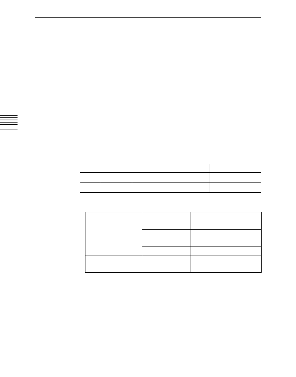
AUX Delegation Buttons Settings (Aux Assign Menu)
To carry out the settings of the AUX delegation buttons in the Aux bus control
block, use the Panel>Aux Assign menu.
To display the Aux Assign menu
In the Engineering Setup menu, select VF2 ‘Panel’ and HF3 ‘Aux Assign.’
The left side of the status area shows the delegation numbers, and the list of
buses set; the right side shows a list of buses that can be assigned.
Assigning a bus to an AUX delegation button
Use the following procedure.
1
Chapter 16 Engineering Setup
Using any of the following methods, select the delegation number and the
bus to be assigned.
• Press directly on the list in the status area.
• Press the arrow keys to scroll the reverse video cursor.
• Turn the knobs to make the setting.
Knob Parameter Adjustment Setting values
1 Deleg No AUX delegation number
2 Bus No Selection of bus to be assigned
a) The setting can be from 1 to 62. The val id setti ngs, however, depend on the number of
buttons and the shift mode.
1 to 62
1 to 105
a)
b)
Number of buttons Shift mode Valid settings
16 OFF 1 to 16
24 OFF 1 to 24
32 OFF 1 to 32
b) The buses that can be assi gned are as follows.
Aux1 to Aux48, Monitor1 to Monitor8, DME1V to DME4V, and DME1K to DME4K
M/E1 Utility1 and 2, P/P Utility1 and 2, Fram e Me mo ry Source1 and 2, Edit Preview,
DSK1 to 4 Fill/Source, M /E-1 EXT DME, P/P EXT DME, DME Ut ilit y 1 and 2
• For a but t on for which you want to disable operation, pre ss [Inhibit].
Setup Relating to Operations From the Control Panel
94
ON 1 to 30
ON 1 to 46
ON 1 to 62
Page 95
2
Press [Set] to confirm the selection.
Setting the AUX delegation button shift operation
To set the operation mode of the rightmost button in the row of AUX
delegation buttons, select one of the following in the <Shift Mode> group of
the Panel>Aux Assign menu.
Hold: Acts as a shift button, and the shifted version of the AUX delegation
buttons is enabled while the button is held down.
Lock: Acts as a shift button, and pressing the button toggles between the
shifted version and the unshifted version of the AUX delegation buttons.
Off: Acts as an AUX delegation button.
Interfacing With External Devi ces (Device Interface
Menu)
To carry out setup relating to connections with external devices, display the
Panel>Device Interface menu.
To display the Device Interface menu
In the Engineering Setup menu, select VF2 ‘Panel’ and HF5 ‘Device
Interface.’
Making control panel GPI input settings
Use the following procedure.
1
In the Panel>Device Interface menu, press [GPI Input].
The GPI Input menu appears.
2
Using any of the following methods, select the settings.
• Press directly on the list appearing in the status area.
• Press the arrow keys to scroll the reverse video cursor.
• Turn knob 1 to make the setting.
Knob Paramet e r Adjustment Setting values
1 Port Port selection 1 to 8
Chapter 16 Engineering Setup
3
In the <Trigger Type> group, select the trigger type.
: Apply the trigger on a rising edge of an input pulse.
: Apply the trigger on a falling edge of an input pulse.
95Setup Relating to Operations From the Control Panel
Page 96
: Apply the trigger on a change in the polarity of the input signal.
(Level): When the input is low or high, the sp ecified signal format
or screen aspect ratio applies. (See “Carrying out level settings” (page
120).)
No Operation: Apply no trigger on an input pulse.
4
In the <Target> group, select the action block.
M/E-1, M/E-2, M/E-3, P/P: Set the action for one of the op erating banks.
Common/Setup: Set an action for something other than the above, or a
setup action.
5
Using any of the following methods, select the action to be set.
Chapter 16 Engineering Setup
• Press directly on the list appearing in the status area.
• Press the arrow keys to scroll the reverse video cursor.
• Turn the knobs to make the setting.
Knob Paramet e r Adjustment Setting values
2 Action Action selection
5 Reg No Register number
a) • Action list when the trigger type is other than “Level”
When Target is M/E-1, M/E-2, or M/E-3: Cut, Auto Trans
Key1 Cut, Key2 Cut, Key3 Cut, Key4 Cut
Key1 Auto Trans, Key2 Auto Trans, Key3 Auto Trans, Key4 Auto Trans
Key1 SS ? Recall, Key2 SS ? Recall, Key3 SS ? Recall, Key4 SS ? Recall
When Target is P/P: Cut, Auto Trans
DSK1 Cut, DSK2 Cut, DSK3 Cut, DSK4 Cut
DSK1 Auto Trans, DSK2 Auto Trans, DSK3 Auto Trans, DSK4 Auto Trans
DSK1 SS ? Recall, DSK2 SS ? Recall, DSK3 SS ? Recall, DSK4 SS ? Recall
FTB Cut, FTB Auto Trans
When Target is Co mmo n/Setup: SS ? R ecall, Effect ? Recall, Effect ? Recall & Run,
KF Run, KF Stop, KF Rewind, Simul, No Action
• Action list when the trigger type is “Level”
When Target is M/E-1, M/E-2, M/E -3, or P/P: No Action
When Targ et is Common/Setup: Format (Overall system se ttings, frame/field rate,
number of lines)
Aspect (overall system settings), No Action
b) When knob 2 sele ction is “Key Snapshot”
c) When knob 2 selection is “Sn apshot”
d) When knob 2 sel e ction is “Effect”
1 to ...
b)
1 to 4
1 to 99
1 to 399
a)
c)
d)
6
Press [Action Set] to confirm the action selection.
The selected setting appears in the status area.
Setup Relating to Operations From the Control Panel
96
Page 97

Carrying out level settings
To set the low level and high level, first set the trigger type to “Level,” then use
the following procedure.
1
In the Panel>Device Interface menu, select the action to be set, and press
[H/L Set].
The H/L Set menu appears.
2
Using any of the following methods, select the settings.
• Press directly on the list appearing in the status area.
• Press the arrow keys to scroll the reverse video cursor.
• Turn knob 1 to make the setting.
Knob Paramet e r Adjustment Setting values
1 No Signal format/screen
3
To apply the selection made in step 2 when the input is the GPI high level,
press [H Set]. To apply the selection made in step 2 when the input is low,
press [L Set].
This confirms the setting, which appears in the status area.
aspect ratio selection
Making control panel GPI output settings
Use the following procedure.
1 to ...
Chapter 16 Engineering Setup
1
In the Panel>Device Interface menu, press [GPI Output].
The GPI Output menu appears.
2
Using any of the following methods, select the settings.
• Press directly on the list appearing in the status area.
• Press the arrow keys to scroll the reverse video cursor.
• Turn knob 1 to make the setting.
Knob Paramet e r Adjustment Setting values
1 Port No Port selection 1 to 8
3
In the <Trigger Type> group, select the trigger polarity.
: The trigger causes the relay contacts to be open-circuit or drives
the output high, and holds this state for the specified pulse
width.
97Setup Relating to Operations From the Control Panel
Page 98
: The trigger causes the relay contacts to be shorted or drives the
output low, and holds this state for the specified pulse width.
: Each time the trigger occurs, the relay contacts are alternately
closed or opened, or the output is switched between high and
low.
Status: Depending on the status, the relay contacts are closed or opened,
or the output is switched between high and low.
No Operation: The trigger has no effect on the relay state o r o utput level.
4
Turning the knobs, select the pulse width and timing to be set.
Knob Paramet e r Adjustment Setting values
3 Pulse Width Pulse width 1 to 60 (fields)
4 Timing Output timing
1 to 3
a)
Chapter 16 Engineering Setup
a) 1: Field 1, 2: Field 2, 3: Any
5
In the <Source> group, select the action block.
M/E-1 to M/E-3 and P/P: Set an action for the M/E or PGM/PST bank.
Common: Set an action for error status.
6
Using any of the following methods, select the action to be set.
• Press directly on the list appearing in the status area.
• Press the arrow keys to scroll the reverse video cursor.
• Turn the knobs to make the setting.
Knob Paramet e r Adjustment Setting values
2 Action Action selection
5 Reg No Register number
a) • Action list when the trigger type is other than “Status”
When Source is M/E-1, M/E-2, or M/E-3: Key1 SS ? Recall, Key2 SS ? Recall, Key3
SS ? Recall, Key4 SS ? Recall, No Action
When Source is P/P: DSK1 SS ? Recall, DSK2 SS ? Recall, DSK3 SS ? Recall, DSK
4 SS ? Recall, No Act ion
When Source is Common: KF Run, No Action
• Action list when the trigger type is “Status”
When Source is M/E-1, M/E-2, or M/E-3: Key1 SS ? Recall, Key2 SS ? Recall, Key3
SS ? Recall, Key4 SS ? Recall
Key1 On, Key2 On, Key3 On, Key4 On, No Action
When Source is P/P: DSK1 SS ? Recall, DSK2 SS ? Recall, DSK3 SS ? Recall, DSK4
SS ? Recall
DSK1 On, DSK2 On, DSK3 On, DSK4 On, No Action
When Source is Common: Error Make, Error Break, No Action
b) When knob 2 sele ction is “Key Snapshot”
c) When knob 2 selection is “Sn apshot”
1 to ...
1 to 4
1 to 99
a)
b)
c)
Setup Relating to Operations From the Control Panel
98
Page 99

7
Press [Action Set] to confirm the action selection.
The selected setting appears in the status area.
Test firing the trigger
To test fire the trigger, press [Test Fire].
This outputs a trigger from the selected output port. This is not output when the
trigger type is “Status.”
Setting the control mode for P-BUS devices
In the <P-Bus Control> group of the Panel>Device Interface menu, select the
mode.
Trigger: When a predetermined button is pressed, the action command
assigned to that button is output, to control an external device.
Timeline: The external device is controlled as a keyframe effect controlled by
the center control panel.
Operation Settings (Operation Menu)
To make settings relating to panel operation, use the Panel>Operation menu.
To display the Operation menu
In the Engineering Setup menu, select VF2 ‘Panel’ and HF6 ‘Operation.’
The status area shows the items that can be set and a list of the settings.
Chapter 16 Engineering Setup
Setting the on-air tally
To set the high tally state reflected on the control panel, select any of the
following in the <Button Tally> group.
System: The overall system tally state is reflected on the control panel.
Independ: The tally state of the switcher only is reflected on the control panel.
Making settings relating to eff ect s
To make settings relating to the functions used when carrying out keyframe
effect operations, use the following procedure.
1
In the Panel>Operation menu, press [Effect Mode].
The Effect Mode menu appears.
The status area shows a list of the items with their settings.
99Setup Relating to Operations From the Control Panel
Page 100

2
Make the following settings as required.
Effect recall mode: To select the initial keyframe state when an effect is
recalled, select [Recall] (do not display the first keyframe) or
[Recall&Rewind] (display the first keyframe) in the <Recall Mode>
group.
Automatic effect saving: To automatically save an effected when it is
recalled after being edited, turn [Effect Auto Save] on.
Setting the Source and Destination names
To set the Source and Destination names used in the system, use the following
procedure.
1
In the <Source/Dest Name> group of the Panel>Operation menu, select the
names to be used from the following.
Chapter 16 Engineering Setup
SW’er Local: Source names set in the Xpt Assign menu, and fixed bus
names
S-Bus Description: Description names set in the routing switcher
S-Bus Type + No.: Type + No. set in the routing switcher (In this case
always eight characters.)
2
In the <Name Display Mode> group, select the method of display in the
source name displays.
Auto: Optimiz e display according to number of char acters. A name of up
to two characters appears as two characters in one line. A n ame of up
to four characters appears as four characters in one line.
Otherwise, up to the first eight characters are shown in two lines.
2 Character: The first two characters appear.
4 Character: The first four characters appear.
Setting the button operation mode
Use the following procedure.
1
In the Panel>Operation> menu, press [Custom Button].
The Custom Button menu appears.
The status area shows a list of the items with their settings.
2
Make the following settings as required.
[ALL] button: To specify the next transition to be selected by pressing the
[ALL] button in the transition control block, press the next transiti on
you want to select, turning it on, in the <Next Trans All> group. If
100
Setup Relating to Operations From the Control Panel
 Loading...