

Page 1

ROUTING SWITCHER
DVS-128
BACKUP CPU BOARD
BKDS-12890
BACKUP POWER SUPPLY UNIT
BKDS-12891
ANALOG AUDIO INPUT BOARD
BKDS-AA10
ANALOG AUDIO OUTPUT BOARD
BKDS-AA11
ANALOG VIDEO INPUT BOARD
BKDS-AV10
ANALOG VIDEO OUTPUT BOARD
BKDS-AV11
AES/EBU INPUT BOARD
BKDS-DA10
AES/EBU OUTPUT BOARD
BKDS-DA11
電気製品は、安全のための注意事項を守らないと、火災
警告
このオペレーションマニュアルには、事故を防ぐための重要な注意事項と製
品の取り扱いかたを示してあります。このオペレーションマニュアルをよく
お読みのうえ、製品を安全にお使いください。お読みになったあとは、いつ
でも見られるところに必ず保管してください。
OPERATION MANUAL
や人身事故になることがあります。
[Japanese/English]
1st Edition
Page 2
日本語
安全のために
ソニー製品は安全に充分配慮して設計されています。しかし電気製品は、安
全のための注意事項を守らないと、火災や感電などにより死亡や大けがなど
人身事故につながることがあり、危険です。
事故を防ぐために次のことを必ずお守りください。
安全のための注意事項を守る
2(J)〜3(J)ページの注意事項をよくお読みください。
オプションユニットの装着について
危険を避けるために、オプションユニットの装着はサービストレーニングを
受けた技術者、もしくはソニーのサービス担当者または営業担当者にご依頼
ください。
警告表示の意味
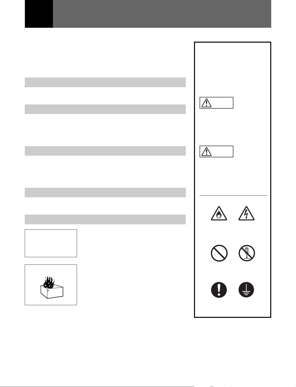
オペレーションマニュアルおよ
び製品では、次のような表示を
しています。表示の内容をよく
理解してから本文をお読みくだ
さい。
警告
この表示の注意事項を守らない
と、火災や感電などにより死亡
や大けがなど人身事故につなが
ることがあります。
定期点検を実施する
長期間安全に使用していただくために、定期点検を実施することをおすすめ
します。点検の内容や費用については、ソニーのサービス担当者または営業
担当者にご相談ください。
故障したら使用を中止する
ソニーのサービス担当者、または営業担当者にご連絡ください。
万一、異常が起きたら
1 電源を切る。
異常な音、におい、
煙が出たら
炎が出たら
/
2 電源コードや接続コードを抜く。
3 ソニーのサービス担当者、または営業担当
者に修理を依頼する。
すぐに電源を切り、消火する。
/
注意
この表示の注意事項を守らない
と、感電やその他の事故により
けがをしたり周辺の物品に損害
を与えたりすることがあります。
注意を促す記号
火災
行為を禁止する記号
禁止
行為を指示する記号
感電
分解禁止
強制
アース線を
接続せよ
Page 3

目次
警告 ....................................................................................................................
注意 ....................................................................................................................
ルーティングスイッチャーシステムのマニュアル構成.............................................
概要 .........................................................................................................................
ハイブリッドルーティングスイッチャーの特長 ...................................................... 5(J)
DVS-128シリーズ構成商品の概要 ............................................................................... 6(J)
ハイブリッドルーティングスイッチャーの制御システム ...................................... 7(J)
ハイブリッドルーティングスイッチャーの機能 ...................................................... 8(J)
S-BUS制御システムの特長 ........................................................................................... 8(J)
システム接続例 .............................................................................................................. 9(J)
各部の名称と働き ..................................................................................................
ルーティングスイッチャーDVS-128 ......................................................................... 11(J)
アナログオーディオ入力ボードBKDS-AA10 ........................................................... 14(J)
アナログオーディオ出力ボードBKDS-AA11 ........................................................... 14(J)
アナログビデオ入力ボードBKDS-AV10 ................................................................... 15(J)
アナログビデオ出力ボードBKDS-AV11 ................................................................... 15(J)
AES/EBU入力ボードBKDS-DA10............................................................................. 16(J)
AES/EBU出力ボードBKDS-DA11............................................................................. 16(J)
エラー表示と対策 ..................................................................................................
主な仕様 ................................................................................................................
ルーティングスイッチャーDVS-128 ......................................................................... 18(J)
バックアップCPUボードBKDS-12890 ...................................................................... 19(J)
バックアップパワーサプライユニットBKDS-12891 .............................................. 19(J)
アナログオーディオ入力ボードBKDS-AA10 ........................................................... 19(J)
アナログオーディオ出力ボードBKDS-AA11 ........................................................... 20(J)
アナログビデオ入力ボードBKDS-AV10 ................................................................... 21(J)
アナログビデオ出力ボードBKDS-AV11 ................................................................... 21(J)
AES/EBU入力ボードBKDS-DA10............................................................................. 22(J)
AES/EBU出力ボードBKDS-DA11............................................................................. 22(J)
2(J)
3(J)
4(J)
5(J)
11(J)
17(J)
18(J)
日
本
語
1 (J)
Page 4
警告
分解禁止
禁止
強制
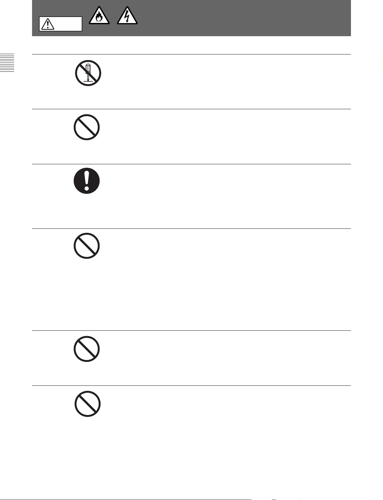
下記の注意を守らないと、
感電火災
火災や感電により死亡や大けがにつながることがあります。
外装を外さない、改造しない
外装を外したり、改造したりすると、感電の原因となります。
内部の調整や設定および点検を行う必要がある場合は、必ずサービストレー
ニングを受けた技術者にご依頼ください。
内部に水や異物を入れない
水や異物が入ると火災や感電の原因となります。
万一、水や異物が入ったときは、すぐに電源を切り、電源コードや接続コー
ドを抜いて、ソニーのサービス担当者または営業担当者にご相談ください。
指定の電源コードを使用する
指定以外の電源コードを使用すると、火災や感電の原因となります。
他の電源コードを使用する場合は、ソニーのサービス担当者または営業担当
者にご相談ください。
禁止
禁止
禁止
電源コードを傷つけない
電源コードを傷つけると、火災や感電の原因となります。
・ 電源コードを加工したり、傷つけたりしない。
・ 重いものをのせたり、引っ張ったりしない。
・ 熱器具に近づけたり、加熱したりしない。
・ 電源コードを抜くときは、必ずプラグを持って抜く。
・ ラックマウントするとき、レールにはさみ込まない。
万一、電源コードが傷んだら、ソニーのサービス担当者に交換をご依頼くだ
さい。
油煙、湯気、湿気、ほこりの多い場所では設置•使用しない
上記のような場所で設置・使用すると、火災や感電の原因となります。
ファンが止まったままの状態で使用しない
ファンが止まると、ステータス表示ランプが赤く点滅します。そのまま使用
し続けると、内部に熱がこもり火災の原因となることがあります。ソニーの
サービス担当者または営業担当者ににご連絡ください。
2 (J)
Page 5
注意
禁止
強制
アース線を
接続せよ
下記の注意を守らないと、
けがをしたり周辺の物品に損害を与えることがあります。
通風孔をふさがない
通風孔をふさぐと内部に熱がこもり、火災の原因となることがあります。
逆さまや横倒しにしない。
•
風通しの悪い、狭いところに押し込まない。
•
毛足の長いじゅうたんや布団の上に置かない。
•
布をかけない。
•
安定した場所に設置する
ぐらついた台の上や傾いたところなどに設置すると、製品が落下してけがの
原因となることがあります。
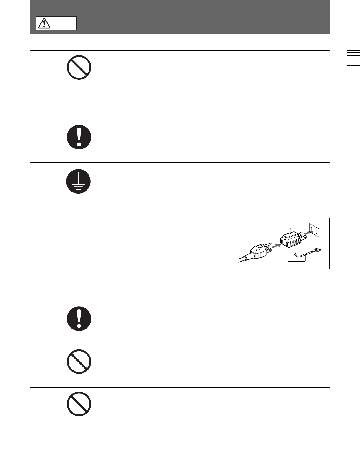
安全アースを接続する
安全アースを接続しないと、感電の原因となることがあります。次の方法で
アースを接続してください。
電源コンセントが3極の場合
•
指定の電源コードを使用することで安全アースが接続されます。
強制
禁止
電源コンセントが2極の場合
•
指定の3 極→2 極変換プラグを使
用し、変換プラグから出ている
緑色のアース線を建物に備えら
れているアース端子に接続して
ください。
安全アースを取り付けることができない場合は、ソニーのサービス担当者ま
たは営業担当者にご相談ください。
人以上で取っ手を持って運搬する
3
取っ手を持たないと、機器が落下してけがの原因となることがあります。
また、けがをふせぐため、運搬は必ず3 人以上で行ってください。
台以上積み上げない
2
ラックを使用せずに2 台以上積み上げると、機器が落下してけがの原因とな
ることがあります。
変換プラグ
アース線
禁止
重い物を載せない、踏み台にしない
本機の上に重い物を載せたり、踏み台にしたりすると、載せたものが落下し
たり、本機が倒れたりして、けがの原因となることがあります。
3 (J)
Page 6

ルーティングスイッチャーシステムのマニュアル構成
ルーティングスイッチャーシステムには、以下のマニュアルが用意
され ています。目的に合わせて、または本書の指示にしたがって
ご覧ください。
オペレーションマニュアル(本書、付属)
ルーティングスイッチャーの簡単な概 要、 接続例、各部の名称、仕
様などの情報を提供し ま す。
インストレーションマニュアル
ルーティングスイッチャーシステムの初期設定や 動作 確認について
説明したマニュアルです。本機だけでなく、ルーティングス イッ
チャーシステムの主要構成機器に関する情報を提供します。
メンテナンスマニュアル
本機の保守に関する情報と、主なブロックおよび基板交換などの
初期サービスに関する情報を提供します。
メンテナンスマニュアル
部品レベルまでのサービスを前提とした情報(調整要項、マウント
図、回路図、詳細な パ ーツリス ト) を提供しま す。入手を希望される
方は、お買い上げいただいた機器の販売担当者にお問い合わせ
ください。
プロトコルマニュアル(別売り)
本機を制御するためのプロトコルに関する情報を提供します。
本機がサポート可能なプロ トコル に 対し、次 のようなマ ニ ュア ル が
用意されています。必要なプロトコルマニュアルについては、お買
い上げいただいた機器の販売担当者にお問い合わせください。
ソフトウェア編(付属)
パート1(付属)
パート2(別売り)
S-BUSリモート用ターミナル制御プロトコル:S-BUSPROTOCOL
ANDCOMMANDSPECIFICATIONS
ソニーカートプロトコル: ROUTING SWITCHER SYSTEM
PROTOCOLANDCOMMANDSPECIFICATIONS
DVS-V3232B/V6464B
(別売り)
ルーティングスイッチャーシステムの技術概要および各種アプリケー
ション情報を提供します。入手を希望さ れ る 方は、お買い上げいた
だいた機器の販売担当者にお問い合わせください。
オペレーション
機器に付属)
アンド インストレーションガイド(別売り
シリーズテクニカルマニュアル
4 (J)
Page 7

概要
放送業務用として新たに開発されたハイブリ ッドルーテ ィングスイッ
チャーDVS-128およびBKDSシリーズオプションボード/ユニット
は、複数の信号フォ ーマットに対応可能な マトリックススイ ッチャーシ
ステムを構築します。
1つの筺体内で、アナログオーディオ/ ビデオ信号およびデジタル
オーディオ信号を、32チャンネル単位で最大128×128のマトリック
スサイズで切り換えます。
実際の信号切り換え操作は、別売りのコントロー ル ユニットBKSR1607/R1608/R3209/R3210などの外部制御機器から行います。
また、本システムを動作させるためには、 あらかじめ PC のター ミナ
ルエミュレーターなどによる、各種の設定(テーブルデータ作成や
システムの設定)が必要です。
放送局やプロダクションハウスで使用されている機器の動作状態
および発生したエラ ー内容を、1台のコンピューターで集中監視す
るISR(InteractiveStatusReporting)システムを使って、本機の
動作状態を監視することもできます。
◆ISRシステムについて詳しくは、インストレー シ ョンマニュアルをご覧くださ
い。
アナログオーディオ・デジタルオーディオの相互乗り入れ
DVS-128システムでは異なる信号フォーマットのマ トリックススイッ
チャーを同時に動作させるこ とができますが、アナログオーディオ
ボードとデジタルオーディオ(AES/EBU)ボードでは同一の信号
フォーマッ トを使用 してい るため、それぞれの相互乗り入れ可能で
す。すなわちアナログオーディオ(ステレオ)信号で入力してデジ
タルオーディオ信号で出力したり、またその逆に動作させるこ とが
でき ます。
将来、アナログオーディ オシステムからデジタルオーディオシステム
への移行がスムーズに実現できます。
デジタ ルオーディオ信号のモニター も容易に行えます。
系統のリファレンス信号に対応
2
DVS-128はビデオリファレンスおよび オ ーディオリ ファレンス(オー
ディ オワードシンク)の入力端子を各2系統備え、信号マトリックス
単位で選択して使用できます。
例えば、放送局のハウスシンクと、それと異なる位相/周波数のリ
ファレンスを、 1つの 筐 体内 で別々のマトリックスのリファレンスとして
使用する こ とができます。
ハイブリッドルーティングスイッチャー
の特長
複数信号フォーマットに対応
DVS-128システムでは、それぞれ32チャンネル単位の入力ボー
ド/出力ボードで構成される オプションボードを本体に装着すること
によって、アナログオーディ オ信号、AES/EBUデジタルオーディオ
信号、アナログビデオ信号に対応します。
1つの筐体内で複数の信号フォーマットのボードを同時に動作させ
ること ができる ため、従来複数台に分けていた筐体を1 台に集約
することが可能です。
最大
128×128
本システムの入出力チャ ンネル数と も最大128チャンネルとなって
おり 、カスケー ド接続に代表されるような拡張手段に頼ることなく、
例えば64×32のデジタルオーディオ信号マトリックスと64×96の
アナログビデオ信号マトリックスを1筐体で実現できます。
リダンダント
信頼性 を重視する放送業務用機器として不可欠なバックア ップ用
コン トロールボードおよびバックアップ用電源ユニットを、それぞれ
別売りCPUボード/パワーサプラ イユニットとして用意しています。
のマトリックスサイズ
リダンダント電源
CPU/
ソニー
S-BUS
本システムは、1本の同軸ケーブルで動作をコントロールできる ソ
ニーS-BUSコントロール方式を採用しています。日常の複雑な操
作も同軸ケーブル1本で実現します。
新開発ソフト仕様に対応
本シス テム は、従来のソニールー ティングスイッチャー制御ソフトか
ら制御マ トリックスサイズや制御内容 をグレードアップした新ソフ トに
対応しています。主な拡充内容は下記の通りです。
• 1024×1024(8レベル)または1024×512(16レベル)に対応。
• 16文字の「デスクリプション(記述)名称」を最大2048まで登録
可能。
• 32種類の「タイプ名」を使用可能。
•タイ ライ ン管理の各グループの要素数を255に拡張。
コントロール方式
5 (J)
Page 8

概要
DVS-128
ルーティングスイッチャー
ハイブリ ッドルーティングスイッチャーシステムの本体外筐ユニットで
す(EIA14RUサイズ)。
基本構成は電源ユニット1台、制御用 CPUボード1枚のみで、
BKDSシリーズの入出力ボードをオプションボー ド用のス ロ ットに 装
着することにより、柔軟にシステムを構築できます。
入力ボード用のス ロット、出 力 ボ ード用のス ロットにそれぞれ4枚ま
で装着し、最大128チャンネルの制御が可能です。
バックアッ プ用の電源ユニットおよびCPUボードも、 オプシ ョンで装
着できます。
バックアップ
DVS-128本体に標準装備されているCPU-275ボードと同じボー ド
です。本体のオプションCPUボード用ス ロットに装着します。
万一標準装備のCPUボードが正常に機能しなくなった場合は、ア
ラームを出してバックアップボードが自動的に動作を開始し、システ
ムの動作を継続します。
シリーズ構成商品の概要
DVS-128
ボード
CPU
BKDS-12890
のどち らでも接続できます。
ケーブルを直接接続するためのD-subケーブルアダプターが付属
されています。
アナログオーディオ出力ボード
アナログオーディ オ信号用マトリックススイッチャー兼 出力ボー ドで
す。メインボード1 枚とコネク ターパネル 1 枚で構 成されています。
基準出力レベルは+4dBm、出力適正負荷インピーダンスは 600
Ω、出力端子はD-sub25ピンコネク ターで す。
128入力×32出力のマトリックス回 路を 備え、 48kHz・20ビットの高
精度でD/A変換し、32チャンネルのアナログオーディオ信号を 出
力します。
本ボードの入力側には、アナログオーディオ入力ボードBKDS-
AA10、AES/EBU(デジタルオーディオ)入力ボードBKDS-DA10
のどち らでも接続できます。
ケーブルを直接接続するためのD-subケーブルアダプターが付属
されています。
アナログビデオ入力ボード
BKDS-AA11
BKDS-AV10
バックアップパワーサプライユニット
BKDS-
12891
DVS-128本体に標準装備されている電源ユニットと同じユニットで
す。本体のオプ ションパワ ーサプ ラ イユニット用スロットに 装 着し、 電
源を二重化します。
万一いずれかのパワーサプライユニットが正 常 に 機 能しなくなった
場合でも、残った1台のユニットで動作を継続します。
アナログオーディオ入力ボード
アナログオーディオ信号用入力ボードです。
メインボー ド1 枚とコネクターパネル 1 枚で構 成されています。
32チャンネルのアナログオーディ オ信号を、ステレオで入力するこ
とができます。
基準入力レベルは+4dBm、入力インピーダンスは600Ω、入力
端子はD-sub25ピンコネクタ ーです。
ボード内部では、全チャンネルを48kHz・20ビットの高精度でステ
レオA/D変換し、AES/EBU相当のデジタルオーディオ信号として
マザー ボ ードの信号バスラインに出力します。
本ボードの出力側には、アナログオーディオ出力ボードBKDS-
AA11、AES/EBU(デジタルオーディオ)出力ボードBKDS-DA11
BKDS-AA10
アナログビデオ信号用入力ボードです。
メインボー ド1 枚とコネクタ ーパネル 1 枚で 構成されています。
NTSC、PALなどの標準ビデオ、コンポーネン トビデオ、HDアナロ
グビデオなどのアナログビデオ信号を、最大32チャンネル入力で
きます。入力端子はBNCコネクターです。
ボード内部では、信号の有無を検出し、入力された信号にペデス
タルクランプ処理、信号出力平衡化処理などを施して、マザーボー
ドの信号バスラインに出力します。
クランプ方式には、8チャンネル毎にセルフク ランプ、リファレンス同
期ク ランプ、ダイレクトを選択できます。
本ボードの出力側には、アナ ログ ビデオ出力ボードBKDS-AV11を
接続できます。
アナログビデオ出力ボード
アナログビデオ信号用マトリックススイッチャー兼出力ボードです。
メインボー ド1 枚とコネクタ ーパネル 1 枚で 構成されています。
128チャ ンネルのアナログビデオ信号をマ トリックス処 理して、 32
チャ ンネルのアナログビデオ信号を出力します。
出力端子はBNCコネクターで、チャンネル1〜8および17〜24は
各2系統の出力を使用できます。
本ボードの入力側には、アナ ログ ビデオ入力ボードBKDS-AV10を
接続できます。
BKDS-AV11
6 (J)
Page 9

AES/EBU
AES/EBUデジタルオーディオ信号用入力ボードです。
メインボー ド1 枚とコネクターパネル 1 枚で構 成されています。
32チャンネルのAES/EBUデジタルオーディオ信号を入力すること
ができます。入力端子はBNCコネクターです。
サンプリング周波数48kHzで、DVS-128本体のリファレンスビ デ オ
端子に入力されるリファ レ ンス信号に同期した信号を入力します。
本ボードの出力側には、アナログオーディオ出力ボードBKDSAA11、AES/EBU(デジタルオーディオ)出力ボードBKDS-DA11
のどち らでも接続できます。
入力ボード
BKDS-DA10
ハイブリッドルーティングスイッチャー
の制御システム
DVS-128ルーティングス イッチャーシステムでは、システ ム設定には
PCのターミ ナルエミ ュレーターを使 用し、信号の切り換えにはコン
トロールパネルなどの制御装置を使用します。
制御システムには、BNC型のREMOTE1端子を使用するS-BUS、
およびD-sub9ピンのREMOTE2端子を使用するRS-422Aの2系
統があります。
2系統の制御を同時に使うこともでき ます。
AES/EBU
AES/EBUデジタルオーディオ信号用マトリックススイッチャー兼出
力ボードです。メイ ンボー ド1 枚とコネク ターパネル 1 枚で構成され
ています。
128入力×32出力のマトリックス回 路を備え、 32チャンネルのAES/
EBU デジタルオーディオ信号を出力します。
出力端子はBNCコネクターで、チャンネル1〜8および17〜24は
各2系統の出力を使用できます。
本ボードの入力側には、AES/EBU(デジタルオーディオ)入力
ボードBKDS-DA10だけでなく、アナログオーディオ入力ボード
BKDS-AA10も接続でき、アナログからデジタルへの変換が簡単に
行えます。
出力ボード
BKDS-DA11
S-BUS
S-BUSは、ソニーがルーティングスイッチャーシステムの制 御用に
開発したプロトコルです。複数のルーティングスイッチャーとコ ン ト
ロールユニットを、1本の同軸ケーブルで接続し、通信することがで
きます。 S-BUSにより制御できる機器の台数は、ルーティングスイッ
チャー、 コ ントロールユニットなど合わせて254台です。
DVS-128システムでは、RS-422AのコマンドをS-BUSコマンドに変
換 することにより、D-sub9ピンのREMOTE2端子を通したS-BUS
制御も可能です。
RS-422A
本シス テムでは、RS-422Aのコマンドを内部でS-BUSのコマンドに
変換して、REMOTE2端子からS-BUS制御することも可能です。
RS-422Aコマンドでそのま ま 制御するモードをダイ レクトモード、SBUSコマンドに変換して制御す るモードをS-BUS変換モードとよび
ます。S-BUS変換モードでは、制御できる系統を拡張し最大256系
統、8レベルの入出力 を制御できますが、応答速度はダイレク トモー
ドより 遅くなり ます。また制御でき る内容も、RS-422A用プロトコルで
行えるものに限定さ れます。
による制御
による制御
レベル設定による複数信号の同時制御
多種類の信号を同時に扱う場合、それぞれの信号別にルーティン
グスイッチャーが必要になり ます。たと えば、VTRで記録を行うため
に必要な信号には、ビデオ、オーディオ、タイムコード、リモートコン
トロールがあり 、それぞれビデオ、オーディオ、タイムコー ド、リモー
トの各ルーティングスイッチャーで 信 号を切り換えます。これらの切
り換えを行う信号を総 称してレベルと呼 びます。本システムでは最
大16種類のレベルを設定し、レベルごとに異なる入力信号の番号
を設定して同時に制御することができます。
7 (J)
Page 10

概要
ハイブリッドルーティングスイッチャー
の機能
ハイブリッドルーテ ィングスイッチャー システムは次のよう な機能を備
えています。
設定した入出力系統の保護機能
設定した出力系統を、他のパネルか ら 切り換 えら れないようにする
プロテクト機 能と、 入力系統をすべてコントロールパネルから隠して
切り換えられないように し、設定したクロスポイ ントを保護するシー
クレット機能を備えています。
クロスポイントを無効にする機能
出力系統ごとに、選択できる入力系統を制限し、特定の入力系統
を指定した出力系統にしか出力できないよ うにすること ができま
す。
パスワード機能
パスワードを設定しておき、オペレーターを制 限 することができま
す。
名称設定機能
入出力端子に名称を設定し、接続する信号を識別できます。名称
は2種類の設定方法があり、ひとつは「タイ プ名(VTR、カメ ラなど
の機器名)+番号」(例:VTR1)で、もうひとつは任意の16文字
の名前をつける「デスクリプション(記述)名称」です。
設定した名称は、別売りのディスプレイユニットBKS-R3280/R3281
およびコ ントロールユ ニットBKS-R1607/R3210に表示させることが
でき ます。
バーチャルマッピッング機能
仮想マトリックス上にクロス ポイ ントを配置することができます。
フリーアサイメント機能
1つの端子名称に、レベルごとに異なる端子番号を割り当てること
ができます。
ファントム機能
複数のクロスポイントを同時に切 り 換 えるこ とができます。
自己診断機能
入出力の有無やエラーの発生を、一次局に接続したコントロール
ター ミナ ルに 送り表 示させることが できます。
S-BUS
S-BUS制御システムでは、複数のルーティングスイッチャーとコント
ロールユニットを1本の同軸ケーブルで接続し、制御信号の通信を
行います。ひとつのS-BUS制御システム内の1台のスイッチャーを
1次局に設定し、この1次局がシステム全体の制御を行います。ほ
かのスイッチャーとコン トロールユニットは 2 次 局になり、 1次局の制
御により信号の通信を行います。
S-BUS制御システムは次のような特長があります。
• 75Ω同軸ケーブル1本による、LAN(LocalAreaNetwork)形式
の制御信号の通信
• 同軸ケーブル(5C-2Vケーブル使用時)を500mまで延長可能
• 電源を切らずにシステムを動作状態のまま、S-BUSラインへの接
続、取り外しが可能
• 1次局に設定 したルーティングスイッチャーは、 複数のS-BUSライ
ンを制御し、 最大254台(1次局を含む)までのルーティングスイッ
チャー とコ ントロールユニットを制御
• 1本のS-BUSラインには、最大128台のルーティングス イッチャー
とコン トロールユニットが接続可能
• 自己診断機能によって検出されたエラーの内容を、S-BUSライン
上の1次局に接続されたPC(ターミナルエミュレーター)に表示
• PC(ター ミ ナルエミ ュ レーター) で設定した内容(システムの設定
やテーブルデータ)およびク ロ ス ポイントデータを、付属のバック
アップソフ トウェアBZR-20を使用してコンピューターのハードディ
スクに保存し、必要に応じて復元可能
制御システムの特長
モニター機能
別売りのコントロールユニットBKS-R1607/R1608/R3209/R3210
(ソフトウェアバージョ ン3.00以上)を使用し、出力信号のモニター
が可能です。
タイライン機能
2台または3台のルーティングスイッチャ ーを接続する信号線を自動
的に選択できます。
8 (J)
Page 11
システム接続例
主要構成機器
本システムは75Ω同軸ケーブルで接続されたS-BUSデータリンク
を核に形成されます。
S-BUSデータリンクの主要構成機器は以下のとおりです。
S-BUS
データリンク主要構成機器
ご注意
DVS-128以外のスイッチャ ーを1次局に設定する こ と もでき ますが、
機能が限定されます。
S-BUS
データリンク
上の種別 使用機器 台数 機能
1次局 ルーティングスイッチャー DVS-128 1 S-BUSデータリンク全体の通信制御。
同時に2次局として動作することも可能。
2次局 ・ビデオルーティングスイッチャー DVS-V1616 最大253台 各機器ごとの通信制御。
・X-Yコントロー ル ユ ニット BKS-R3210
ターミナル ターミナル エミュレーター P C 一 般 1 システムの各 種 設 定 。
ス
イ
ッ
チ
ャ
・オ ー ディオルーティングスイッチャー DVS-A3232
ー
・RS-422Aルーティングスイッチャー DVS-RS1616
・タイムコードルーテ ィングスイッチャー DVS-TC3232
リ
モ
・32ボタ ンコ ントロール ユ ニット BKS-R3209
ー
ト
・ユニバーサルコ ントロー ル ユ ニット BKS-R1607
コ
ン
ト
・16ボタ ンコ ントロール ユ ニット BKS-R1608
ロ
ー
・8 デステ ィネーシ ョンコントロールユニット BKS-R3206
ル
ユ
ニ
・シングルステータスディ スプレイユニット BKS-R3280
ッ
ト
・シングルステータスディ スプレイユニット BKS-R3281
DVS-V3232B/M 1次局からの指示に従って通信を行う。
DVS-V6464B/M
S-BUSラインで発生 したエラーの表示と管理。
接続時のご注意
• 1次局に使用するルーティングスイッチ ャーでは、内部CPUボー
ドのP/SスイッチをPに(スイッチ表示がM/SのモデルではMに)
設定します。
• 2次局に使用するルーティングスイッチ ャーでは、内部CPUボー
ドのM/Sスイッチ(DVS-128ではP/Sスイッチ)をSに設定します。
• 1本のS-BUSラインに接続できる2次局は最大128台です。
• 1本のS-BUSラインのケーブル長は最大500m(5C-2Vケーブル
使用時)。
• S-BUSラインの最終機に 取り付けるT 型ブリ ッジ、および各スイッ
チャーの使用しないREMOTE1端子は、必ず75Ω終端器で終
端してく ださい。
• 2次局のルーティングスイッチャーのREMOTE1端子は1個のみ
使用可能です。
• REMOTE 4端子(モニターライン)にはリモートコントロー ル ユ
ニットBKS-R1607/R1608/R3209/R3210(バージョン3.00以上)を
接続できます。
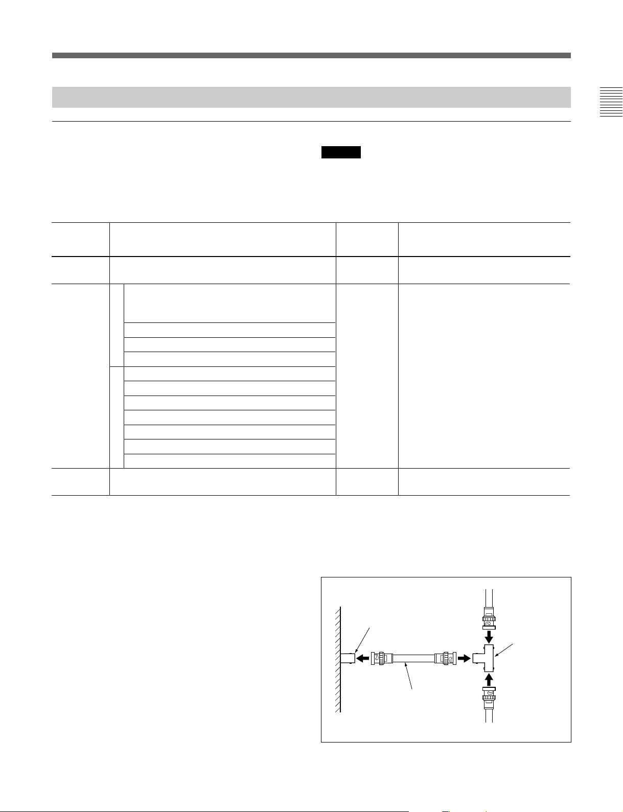
型ブリッジ(Bタイプ)の使いかた
T
DVS-128には、BタイプのT型ブリッジが付属しています。
使用するときは、50cm以下の同軸ケーブル(5C-2V)を用意し、次
のように接続してください。
REMOTE 1
(BNC
5C-2V
端子
型、メス
同軸ケーブル
)
型ブリッジ
T
タイプ
(B
)
(50 cm以下)
9 (J)
Page 12
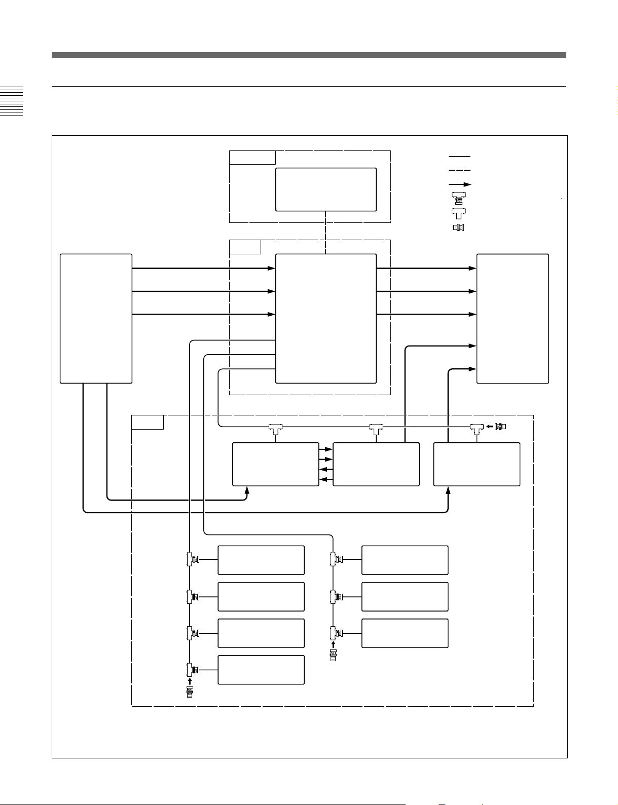
概要
接続例
DVS-128を1次局とするS-BUSデータリンクの接続例を示します。
ソース
VTR
アナログビデオ
アナログオーディオ
チャンネル1/2
アナログオーディオ
チャンネル3/4
2次局
ターミナル
1次局
REMOTE 1
C
B
A
パーソナルコンピュータ
(ターミナルエミュレーション)
REMOTE 3
ハイブリッド
ルーティングスイッチャー
DVS-128
(P)
アナログビデオ
アナログオーディオ
チャンネル1/2
アナログオーディオ
チャンネル3/4
デジタルビデオ
タイムコード
:S-BUS
:RS-232C
:信号系ライン
:T型ブリッジ(Aタイプ)
:T型ブリッジ(Bタイプ)
:75Ω終端器
デスティネーション
VTR
タイムコード
デジタルビデオ
リモートコントロール
ユニット
ビデオ
ルーティングスイッチャー
DVS-V6464M
(S)
BKS-R1607
リモートコントロール
ユニット
BKS-R1608
リモートコントロール
ユニット
BKS-R3209
リモートコントロール
ユニット
BKS-R3210
(P):内部CPUボードのP/SスイッチをPに設定(前ペー ジ参照)
(S):内部CPUボードのM/SスイッチをSに設定(前ペー ジ 参照)
ビデオ
ルーティングスイッチャー
DVS-V6464M
(S)
リモートコントロール
ユニット
BKS-R3206
ディスプレイ
ユニット
BKS-R3280
ディスプレイ
ユニット
BKS-R3281
タイムコード
ルーティングスイッチャー
DVS-TC3232
(S)
10 (J)
Page 13
各部の名称と働き
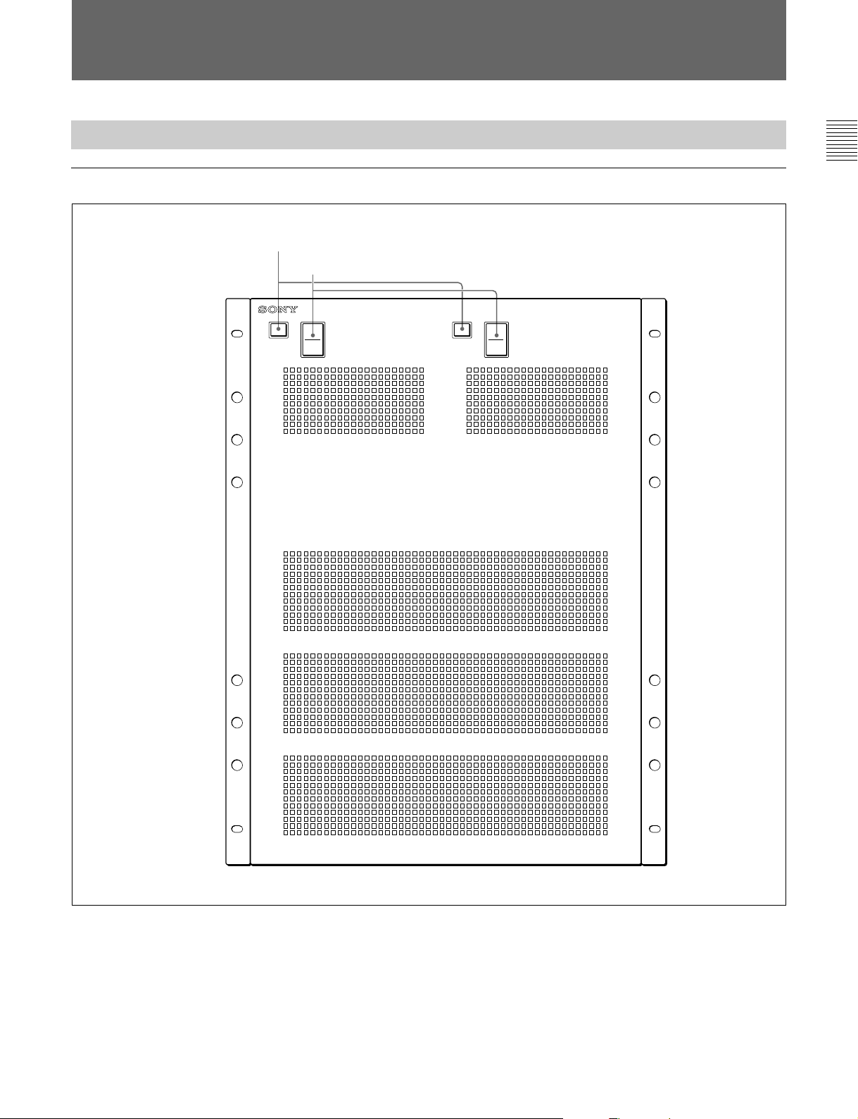
ルーティングスイッチャー
前面パネル
DVS-128
1
ステータス表示ランプ
2
POWER
POWER
A
スイッチ
ROUTING SWITCHER
POWER
B
DVS-128
1 ステータス表示ランプ
ランプの色や点滅によって、本機の状態を表示します。
本機の電源が入り、正常に動作してい るとき は緑に点灯し ます。エ
ラーが発生すると、緑の点滅、赤の点灯/点滅で知らせます。
右側の表示ランプ(B)は、別売りのバックアップパワーサプライユ
ニットBKDS-12891を取り付けたときのみ有効です。
◆詳しくは 「エラー表示と対策」(17(J)ページ)をご覧く だ さい。
2
POWER
(電源)スイッチ
本機の電源をON/OFFします。
右側のスイッチ(B)は、別売りのバックアップパワーサプライ ユ ニッ
トBKDS-12891を取り付けたときのみ有効です。
11 (J)
Page 14

各部の名称と働き
後面パネル
3
4
5
6
7
8
端子
AC IN
U端子
同期信号入力端子
同期信号入力端子
REMOTE 1
REMOTE 2
A
B
端子
端子
1
出力基板用スロット
1 出力基板用スロット
別売りの出力ボードBKDS-AA11、BKDS-AV11、またはBKDSDA11を装着します。
2 入力基板用スロット
別売りの入力ボードBKDS-AA10、BKDS-AV10、またはBKDSDA10を装着します。
12 (J)
2
入力基板用スロット
3
AC IN(AC
9
REMOTE 3
q;
REMOTE 4
電源入力)端子
端子
端子
AC電源コードを使って、 AC電源に接続します。
ご注意
端子 B は、別売りの バックアップパワーサプライユニットBKDS12891を取り付けたときのみ有効です。
4 U(アース)端子
Page 15

5 同期信号入力端子A (
A系統の同期信号入力用です。
(リファレンスビデオ入力 ):アナロ グの リファレンスビデ
REF IN
オ信号(CCIR624に準拠したブラックバースト信号)を入力し
ます。
2個の端子は内部でスルー接続されています。スルーアウト信
号を使用しないときは、使用しない端子に市販の75Ω終端器
を接続して終端してく ださい。
WORD SYNC IN
オワードシンク信号を入力します。
2個の端子は内部でスルー接続されています。スルーアウト信
号を使用しないときは、使用しない端子に市販の75Ω終端器
を接続して終端してく ださい。
ご注意
信号の切り換えを、リフ ァレンス信号に同期さ せたいとき は、CPU275基板のS4-1スイッチをSYNC側に設定してください。さらに、 信
号の切り換えタイミング(奇数フィールドまたは偶数フィールド)を
PC(ターミナルエミュレーター)で設 定します。
◆詳しくはメンテナンス マニュアルおよびインストレーシ ョンマニュアルをご
覧く ださい。
(オーディオワードシンク入 力):オーディ
BNC
型)
8
REMOTE 2
ソニー9ピンリ モートコン トロールケー ブルを使い、RS-422Aインター
フェースを 介して、外 部のコン トローラーと接続します。
コン トロールター ミナルでS-BUS変換モードに設定すると、この端子
を使ってS-BUS制御が可能になります。
◆詳しくは、インストレーシ ョンマニュアルをご覧ください。
9
REMOTE 3
本機をシステムの1次局(内部のP/SスイッチをP) に設定 してい
る場合、システムの動作に必要な設定を行うためのコントロー ル
ター ミナ ルを、 この端子に接続します。また、ISRシステムを使って
本機を監視する場合は、ISRシステムをこの端子に接続します。
◆ISRシステムについて詳しくは、インストレー シ ョンマニュアルをご覧くださ
い。
ご注意
•この端子を使うときは、CPU-275基板のS4-3をTERM側に、S4-2
をP側に設定してください。
◆詳しくは、メンテナンスマニュアルをご覧く ださ い。
• 接続にはインチねじ付きのD-sub9ピンコネク ターをお使いく ださ
い。
(リモート2)端子A、B(
(リモート3)端子(
D-sub 9
D-sub 9
ピン)
ピン)
6 同期信号入力端子B (
B系統の同期信号入力用です。それぞれA系統の入力端子と同
様に機能 し ま す。
AとB の切り換えは、各ボー ドのス イッチで行います。
7
REMOTE 1
S-BUS制御を行うために、コン トロ ールユニ ットやルーティ ングスイッ
チャーを同軸ケーブルで接続します。本機が1次局
SスイッチがP)に設定されている場合は、3つの端子に合計253台
までの リモートコントロールユニットやほかのルーティングスイッ
チャーを接続できます。本機が2次局
に設定 されている 場合は 、どれかひとつの端子 を付属のT型ブリッ
ジ(B)を使ってS-BUSリンク と接続します。 使用しない端子には、
1次局、2次局とも付属の75Ω終端器を接続してください。
◆詳しくは、9(J)ページの「システム接続例」をご覧く ださい。
(リモート1)端子A、B、C(
BNC
型)
BNC
1)
(内部のP/
1)
(内部のP/Sスイッチが S)
型)
q;
REMOTE 4
出力信号をモニターするときに、モニター系の信号 を制御するコン
トロール信号を入力します。
リモート コン トロー ル ユ ニッ トBKS-R1607/R1608/R3209/R3210
(バージョン3.00以上)を接続できます。
(リモート4)端子(
BNC
型)
..............................................................................................................................................................................................................................................................................
1)S-BUSプロトコ ル に よるリモート制御では、1本の同軸ケーブルラインで
データ伝 送 路を構 成し、データリンク内の複数の機器(ルーティングスイッ
チャー、コン トロールユニットなど) が、時分割方式でそのデータ伝送路を利
用します。 各機器のうち、伝送路利用の管理を行うのが1次局で、2次局は
1次局の指示に従 って伝送路を利用します。このため、 多数の2次局が接
続されると、数に応じて応答速度が遅くなります。
13 (J)
Page 16
各部の名称と働き
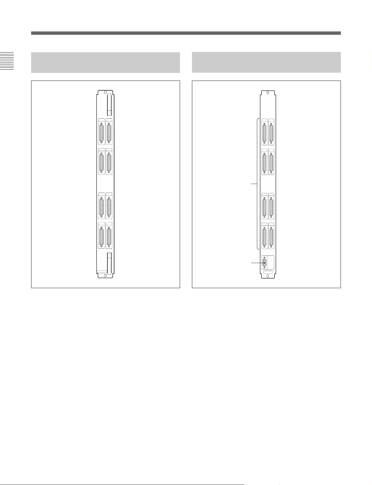
アナログオーディオ入力ボード
BKDS-AA10
INPUTS
15
26
37
48
アナログオーディオ出力ボード
BKDS-AA11
OUTPUTS
15
26
1
37
4
8
BKDS-AA10
INPUTS(入力)端子1〜8(D-sub 25
ピン、メス)
アナログオーデ ィオ信号を入力します。
各端子にそれぞれ4チャンネル、ボード1枚で合計32チャンネルの
アナログオーディオ信号をステレオで入力できます。
MONITOR
2
1
OUTPUTS(出力)端子1〜8(D-sub 25
OUT
BKDS-AA11
ピン、メス)
アナログオーデ ィオ信号を出力します。
各端子からそれぞれ4チャンネル、ボード1枚で合計32チャンネル
ステレオのアナログオーデ ィオ信号を出力できます。
2
MONITOR OUT(
モニター出力)端子(
D-sub 9
ピン、メ
ス)
アナログオーディオ出力をス テレオでモニターできま す。
チャンネル1〜32の本線出力から任意の1チャンネルを選択して出
力できます。
14 (J)
Page 17
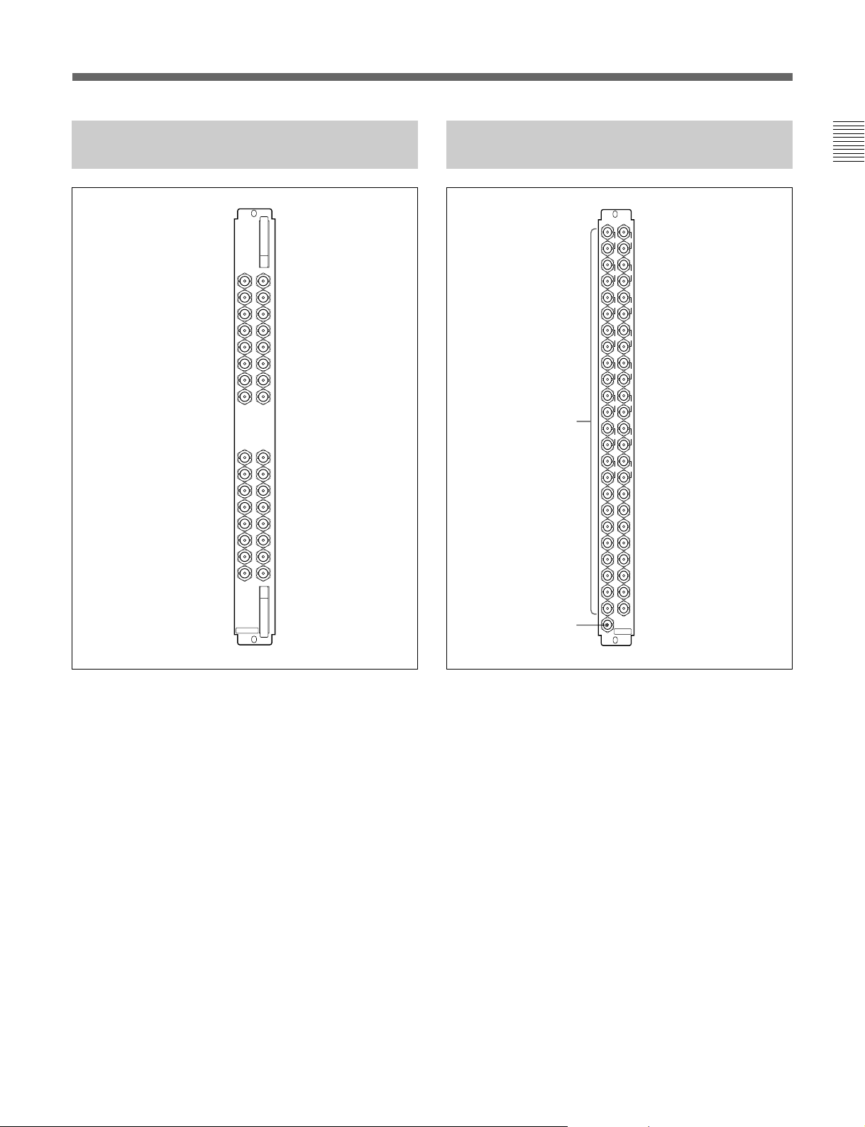
アナログビデオ入力ボード
BKDS-AV10
アナログビデオ出力ボード
BKDS-AV11
INPUTS
BKDS-AV10
OUTPUTS
117
117
218
319
420
521
622
723
824
218
319
420
521
622
1
32
MONITOR
OUT
BKDS-AV11
723
824
925
1026
1127
1228
1329
1430
1531
16
925
1026
1127
1228
1329
1430
1531
1632
2
INPUTS(入力)端子1〜32(BNC
アナログビデオ信号を入力します。
型)
1
OUTPUTS(出力)端子1〜32(BNC
型)
アナログビデオ信号を出力します。
チャンネル1〜8および 17〜24は、ぞれぞれ2個の端子を使用で
きます。
2
MONITOR OUT(
モニター出力)端子(
BNC
型)
アナログビデオ出力をモニターできます。
チャンネル1〜32の本線出力から任意の1チャンネルを選択して
出力できます。
15 (J)
Page 18
各部の名称と働き
AES/EBU
入力ボード
INPUTS
BKDS-DA10
BKDS-DA10
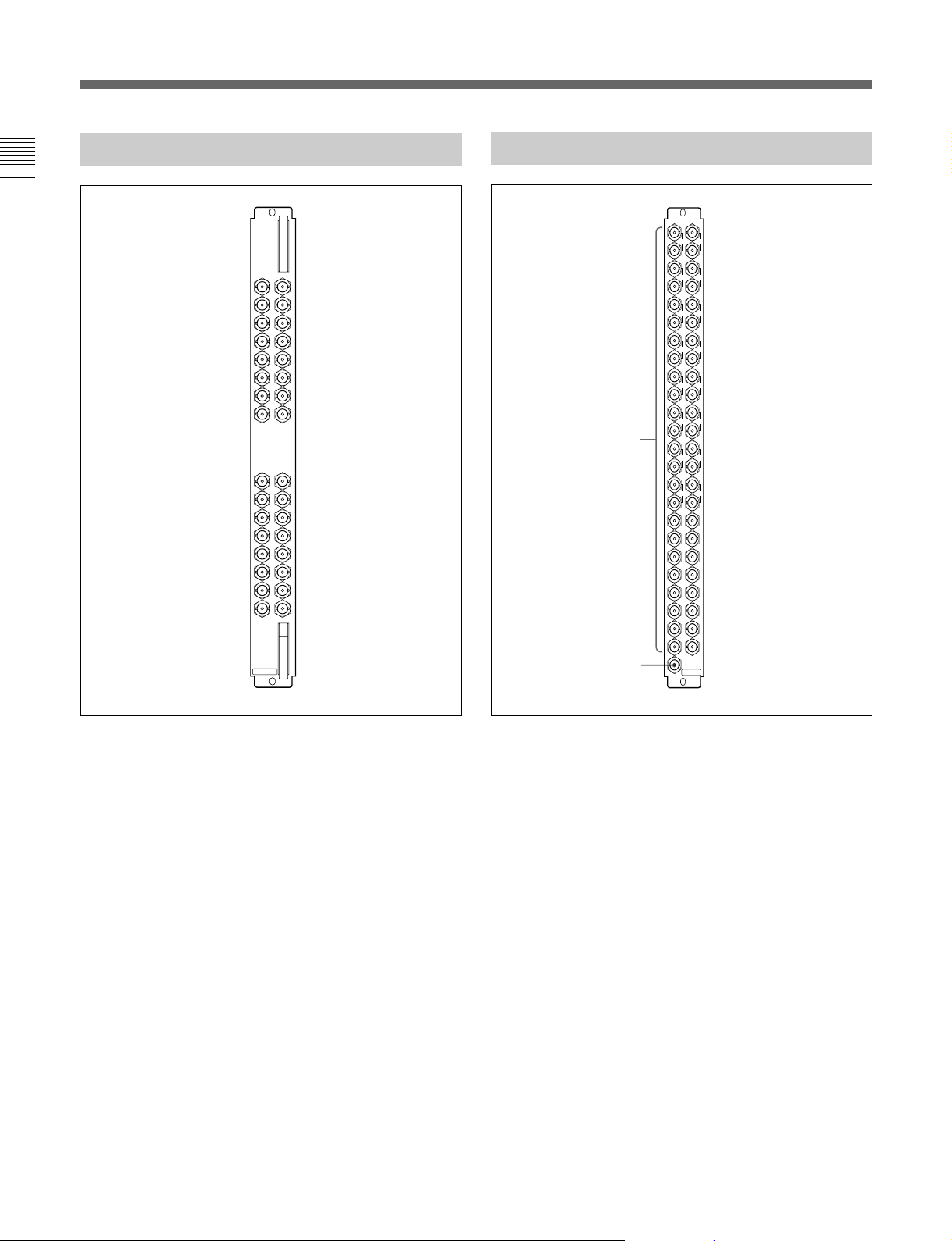
117
218
319
420
521
622
723
824
925
1026
1127
1228
1329
1430
1531
1632
AES/EBU
出力ボード
OUTPUTS
1
32
2
MONITOR
BKDS-DA11
BKDS-DA11
117
218
319
420
521
622
723
824
925
1026
1127
1228
1329
1430
1531
16
OUT
INPUTS(入力)端子1〜32(BNC
型)
AES/EBUデジタルオーディオ信号を入力しま す 。
1
OUTPUTS(出力)端子1〜32(BNC
型)
AES/EBUデジタルオーディオ信号を出力しま す 。
チャンネル1〜8および17〜24は、ぞれぞれ2個の端子を使用で
きます。
2
MONITOR OUT(
モニター出力)端子(
BNC
型)
AES/EBUデジタルオーディオ出力をモニター できます。
チャンネル1〜32の本線出力から任意の1チャンネルを選択して
出力できます。
16 (J)
Page 19
エラー表示と対策
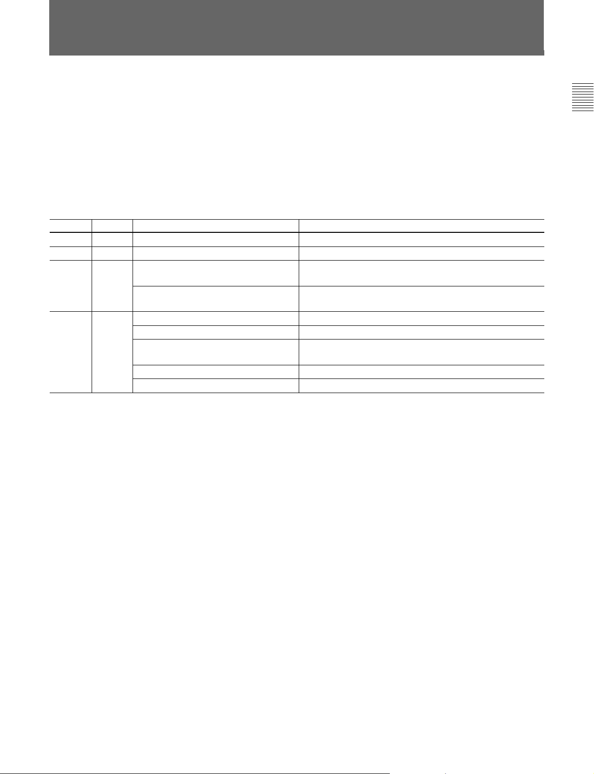
本機は、電源投入またはリセットと同時に自己診断を行い、その後
の動作中にも定期的に自己診断を実行します。エラーを検出する
と、ただちにステー タス表示ラ ンプによって知らせ、その内容をコン
トロールターミ ナルに出力します。また、 本機がISRシステムに接続
さ れている場合は、エラーの内容をISRシステムのホストコンピュー
ターに送ります。
ステータス表示ランプによって表示されるエラーと対策
ランプ色 状態 エラーの内要 対策
緑 点灯 正常に作動している 。 −
緑 点滅 同期信号が検出できない。 A側のREFIN端子にリファレンスビデオ信号を入力する。
赤 点灯 標準およびバック アップの両方のCPUボードが 不良のCPUボードを交換する。
装着されているが、一方が動作 していない。
2台のパワーサプライユニットが装着さ れ ている 不良のパワーサプライユニットを交換する。
が、一方の電圧が低下している。
赤 点滅 S-BUSデータリンクが断線した。 応答のない機器との接続をし直す。
75 Ω終端器が取 り付け られていない。 75 Ω終端器を取 り付ける。
クロスポイ ントエラー。入力端子と出力端子で 入力/出力ボードの動作を確認 し 、不良ボードを交換する。
検出している信号の有無があっていない。
ROMまたはRAMエラー。 CPUボードを交換 する。
ファン不 良。 ファンユ ニットを交換する。
また、 CPU-275基板上のERRORNo.インジケー タ ーに表示さ れる
2 桁 のエラーコー ドにより、簡易的に故障箇所を知ることができま
す。
ここでは、ステー タス表示ランプによって表示されるエラー と対策を
示します。
◆ERRORNo.インジケーターに表 示されるエラーコー ドと対策に ついては、
メ ンテナンスマニュアルをご覧く ださい。
17 (J)
Page 20

主な仕様
ルーティングスイッチャー
一般
電源 AC100〜240V、50/60Hz
消費電流 AC100V:最大 9.4A
AC240V:最大 3.8A
供給可能電流 + 5.6VDC:最大45A
− 5.6VDC:最大45A
動作温度 5℃〜 40℃
保存温度 −20℃〜+60℃
質量 約 33kg(別売りボード/ユニット含まず )
最大外形寸法 424×620×550mm
(幅 / 高さ/ 奥行き)
組み込みユニット
付属ユニット AC パワーサプライユニット(1)
CPUコントロールボード(1)
別売りユニット バックアップパワーサプライユニット
バックアップ C P U コン トロールボード
信号入力ボード
アナログオーデ ィオ用
アナログ ビデオ用
デジタ ルオーディオ用
(各種混在にて4枚まで実装可能)
信号出力ボード
アナログオーデ ィオ用
アナログ ビデオ用
デジタ ルオーディオ用
(各種混在にて4枚まで実装可能)
DVS-128
入力端子 WORDSYNCINA/B:
BNCコネクター(2)、不平衡、ループス
ルー出力付き、ハイイン ピーダンス受け
(75Ω終端にて使用)
入力リターンロス 42dB以上(DC〜6MHz)
内部同期 入力ワードシンク信号がない場合は、REF
IN端子のリファレンスビデオに自動同期
リモートコントロール端子
REMOTE1 S-BUSリモート端子:BNCコネクター(3)、
47kΩ入力
データ転送速度:312.5/1250kbps
信号伝達距離500m(75Ω同軸ケ ーブル
5C-2V使用時)
REMOTE2 RS-422A信号規格準拠
(S-BUSコマンドに変換可)
D-sub9ピン(2)、100Ω/10kΩ
データ転送速度38.4kbps
REMOTE3 RS-232C信号規格準拠
ター ミナル接続用
D-sub9ピン、オス
(インチねじ止め)(1)
ター ミナル 9600/38400bpsDTR制御
8ビット、パリティなし、チェックなし、ストッ
プビット1
ISR 9600bps
7ビット、オッドパリテ ィ、ス トップビッ ト1
REMOTE4 S-BUSリモート端子:BNCコネクター(1)
REMOTE1と同仕様
各種出力ボードのモニター出力制御用
ビデオ同期入力
接続可能入力信号 アナログビデオリフ ァ レンス信号(ブ ラック
バースト信号)またはアナログHDビデオ
(3値シンク)リファレンス信 号
AおよびB の 2 系統を入力可
入力端子 REFINA/B:
BNCコネクター(2)、不平衡、ループス
ルー出力付き、ハイインピーダンス受け
(75Ω終端にて使用)
入力リターンロス 42dB以上(DC〜5MHz)
ワードシンク入力
接続可能入力信号 48kHzオーディオワードシンク
0.5〜5Vp-p方形波
AおよびB の 2 系統を入力可
18 (J)
付属品
オペ レーションマニュアル(1)
インストレーシ ョンマニュアルソフトウェア編(1 )
メンテナンスマニュアルパート1(1)
75Ω終端器(3)
T型ブリッジ( B タイプ)(1)
フロッ ピーディ スク(バックアプソフトウェアBZR-20)(1)
本機の仕様および外観は、改良のため予告なく変更することがあ
りますが、ご了承ください。
DVS-128は、「高調波ガイドライ ン適合品」です。
Page 21

バックアップ
本ボードはDVS-128本体に標準装備されているCPUボードと同 一
のボードで、機能・性能とも同一です。
一般
電源 +5.6VDC:1.0A
消費電力 約5.7W
動作温度 5℃〜40℃
外形寸法 237×381mm(高さ/奥行き)
質量 約0.7kg
付属品
オペ レーションアンドインストレーシ ョンガイド(1)
CPU
ボード
BKDS-12890
アナログオーディオ入力ボード
BKDS-AA10
一般
電源 +5.6VDC:2.2A
−5.6VDC:1.2A
消費電力 約19W
動作温度 5℃〜40℃
外形寸法
メインボー ド: 440×381mm(高さ/奥行き)
コネクターパネル: 41×467×102mm(幅/高さ/奥行き)
質量
メインボー ド: 約1.5kg
コネクターパネル: 約0.8kg
本機の仕様および外観は、改良のため予告なく変更することがあ
りますが、ご了承ください。
バックアップパワーサプライユニット
BKDS-12891
本ユニットはDVS-128本体に標準装備されているパワーサプライユ
ニットと同一のユニットで、機能・性能とも同一です。
一般
電源 AC100〜240V、50/60Hz
消費電流 AC100V:最大9.4A
AC240V:最大3.8A
供給可能電流 +5.6VDC:最大45A
−5.6VDC:最大45A
動作温度 5℃〜40℃
最大外形寸法 193×156×423mm
(幅/高さ/奥行き)
質量 約8.0kg
付属品
オペ レーションアンドインストレーシ ョンガイド(1)
本機の仕様および外観は、改良のため予告なく変更することがあ
りますが、ご了承ください。
入力
アナログオーデ ィオ入力端子
D-sub25ピンコネク ター(メス)(8)
各 4チャンネル×ステレオ
平衡(電子バランス)
入力チャンネル数 32チャンネル×ステレオ
入力インピーダンス 600Ω/20kΩ
(内部スイッチで選択可能)
基準入力レベル +4dBm
(−10dBm〜+8dBm連続可変)
基準信号出力 AES/EBUフォーマットデジタル変換出力
変換性能
A/D
量子化 20ビット直線/48kHzサンプリング
ヘッドルーム 20dB(基準レベルにて)
周波数特性 20Hz〜20kHz
±0.1dB以内(BKDS-DA11受け時)
+0.2
dB以内(BKDS-AA11受け時)
−0.3
(いずれも1kHz基準)
歪み率 0.05%以下(1kHz、基準レベル、30kHz
ローパス )
S/N比 95dB以上(BKDS-DA11受け時)
90dB以上(BKDS-AA11受け時)
(いずれも最大出力レベル、30kHzロー
パス)
クロス トーク −90dB以下(15kHz以下にて)
プリエンファシス 対応せず
シグナルディレイ 約0.6ms(BKDS-DA11受け時)
約1.0ms(BKDS-AA11受け時)
19 (J)
Page 22

主な仕様
リファレンス入力
オーディオクロック DVS-128 のWORDSYNCINA または B
端子に入力されたオーディオワードシンク
に同期(A/B はメインボード上の スイッチ
で選択)
入力がない場合は、それぞれの REFIN
端子のリファレンスビデオに自動同期
付属品
オペレーションアンドインストレーシ ョンガイド(1)
D-sub25ピンケーブルアダプター(8)
本機の仕様および外観は、改良のため予告なく変更することがあ
りますが、ご了承ください。
アナログオーディオ出力ボード
BKDS-AA11
一般
電源 +5.6VDC:5.5〜8.6A
−5.6VDC:4.1〜7.0A
消費電力 約55〜88W
(オーディオ出力レベルによる)
動作温度 5℃〜40℃
外形寸法
メインボー ド: 440×381mm(高さ/奥行き)
コネクターパネル: 41×467×102mm(幅/高さ/奥行き)
質量
メインボー ド: 約2.5kg
コネクターパネル: 約0.8kg
マトリックススイッチャ−部
入力信号 AES/EBUデジタルオ−ディオ信号バス
マトリックスサイズ 128入力×32出力
切り 換え方式 リ ファレンスビ デ オ 同 期 式
出力
アナログオーデ ィオ出力端子
D-sub25ピンコネク ター (メス)(8)
各 4 チャンネル×ステレオ
平衡(トランスレス電子バランス差動出力)
出力チャンネル数 32チャンネル×ステレオ
モニター出力端子 D-sub9ピンコネクタ ー(メス)(1)
出力チャンネル数 任意の1チャンネル×ステレオ
出力インピーダンス 約 20 Ω
適正負荷 600Ω
変換性能
D/A
量子化 20ビット直線/48kHzサンプリング
ヘッドルーム 20dB(基準レベルにて)
基準出力レベル +4dBm
(−10dBm〜+8dBm連続可変)
最大出力レベル + 24dBm(600負荷時)
+25dBs以 上 (ハイインピーダンス受け
時)
周波数特性 20Hz〜20kHz
±0.2dB以内
+0.2
dB以内(BKDS-AA10接続時)
−0.3
(いずれも1kHz基準)
歪み率 0.05%(1kHz、基準レベル、30kHzロー
パス)
S/N比 93dB以上(BKDS-DA10接続時)
90dB以上(BKDS-AA10接続時)
(いずれも最大出力レベル、30kHzロー
パス)
クロス トーク −90dB以下(15kHz以下にて)
シグナルディレイ 約0.4ms(BKDS-DA10より入力時)
約1.0ms(BKDS-AA10より入力時)
リファレンス信号
オーディオクロック 48kHzワードシ ンク
DVS-128のWORDSYNCINAまたはB
端子に入力されたオー ディオワードシンク
に同期(A/Bはメインボード上のスイッチ
で選択。 ただし必ず入力ボードと同一側
を選択する。)
入力がない場合は、リファレンスビ デ オ に
自動同期
リファレンスビ デ オ マトリックススイッチャ−部の切り換えタイミ
ングを生成。REFINAまたはB をメイン
ボード上のスイッチで選択可能
付属品
オペ レーションアンドインストレーシ ョンガイド(1)
D-sub25ピンケーブルアダプター(8)
本機の仕様および外観は、改良のため予告なく変更することがあ
りますが、ご了承ください。
(BKDS-DA10接続時)
20 (J)
Page 23

アナログビデオ入力ボード
BKDS-AV10
アナログビデオ出力ボード
BKDS-AV11
一般
電源 +5.6VDC:1.1A
−5.6VDC:0.8A
消費電力 約11W
動作温度 5℃〜40℃
外形寸法
メインボー ド: 440×381mm(高さ/奥行き)
コネクターパネル: 41×467×102mm(幅/高さ/奥行き)
質量
メインボー ド: 約1.3kg
コネクターパネル: 約1.0kg
入力
アナログビデオ入力端子
BNCコネクター(32)
75Ω、不平衡
入力チャンネル数 32チャンネル
入力信号 1Vp-pSD/HDアナログビデオ信号
入力リターンロス 40dB以上(DC〜5MHz)
信号処理
クランプ方式 セルフクランプ方式、リファレンスクランプ
方式、またはダイレクト結合方式(8チャン
ネル単位で選択可)
信号有無検出 シンク信号レベル検出方式
性能
◆BKDS-AV11の「性能」を参 照してく ださい。
付属品
オペ レーション&インストレーシ ョンガイド(1)
本機の仕様および外観は、改良のため予告なく変更することがあ
りますが、ご了承ください。
一般
電源 +5.6VDC:5.0A
−5.6VDC:3.5A
消費電力 約48W
動作温度 5℃〜40℃
外形寸法
メインボー ド: 440×381mm(高さ/奥行き)
コネクターパネル: 41×467×102mm(幅/高さ/奥行き)
質量
メインボー ド: 約1.4kg
コネクターパネル: 約1.1kg
マトリックススイッチャ−部
マトリックスサイズ 128入力×32出力
切り 換え方式 ダブルラ ッ チ、ブランキングスイッチング
方式
出力
アナログビデオ出力端子
BNCコネクター(48)
75Ω、不平衡
出力チャンネル数 32チャンネル
チャンネル1〜8および16〜24は各2系統
出力
モニター出力端子 BNCコネクター(1)
出力チャンネル数 任意の1チャンネル
出力リターンロス 42dB以上(DC〜5MHz)
性能
入力側にBKDS-AV10を使用した場合の総合特性
DG 0.1%以下(4.43MHz、APL10〜 90%に
て)
DP 0.1°以下(4.43MHz、APL10〜90%にて)
周波数特性 100kHz〜10MHz±0.15dB以内
(1MHz基準)
+0.5
10MHz〜30MHz
基準)
クロス トーク −60dB以下(5MHz以下にて、ワースト
ケース)
S/N 73dB以上(5MHzローパス)
入力間位相差 1.5°以内
スイ ッチングステップ ±50mV以内
チルト 0.5%以下
dB以内(1MHz
−1.0
21 (J)
Page 24

主な仕様
Kファクター 0.5%以下
利得安定度 ±0.15dB以内
総合遅延時間 約32ns
付属品
オペレーションア ンドインストレーシ ョンガイド(1)
本機の仕様および外観は、改良のため予告なく変更することがあ
りますが、ご了承ください。
AES/EBU
一般
電源 +5.6VDC:1.8A
消費電力 約10W
動作温度 5℃〜40℃
外形寸法
メインボー ド: 440×381mm(高さ/奥行き)
コネクターパネル: 41×467×102mm(幅/高さ/奥行き)
質量
メインボー ド: 約1.3kg
コネクターパネル: 約1.0kg
入力
入力端子 BNCコネクター(32)、75Ω、不平衡
入力信号フォーマット AES/EBUデジタルオ−ディオ信号
入力信号条件 リファレンス用ワードシンクに同期した 48
入力チャンネル数 32チャンネル
標準入力レベル 1Vp-p
入力リターンロス 26dB以上(0.1MHz〜6MHz)
受信性能
信号伝達距離 600m以上(信号源レベル1Vp-p、5C-2V
入力ジッターマージン ±30ns以上
シグナルディレイ 約0.04ms(BKDS-DA11受け時)
入力ボード
ANSIS.4.40(AES-3)
kHzサンプリングの AES/EBUデジタル
オ−ディオ信号
ケーブル使用時)
約0.4ms(BKDS-AA11受け時)
BKDS-DA10
AES/EBU
一般
電源 +5.6VDC:1.7A
消費電力 約9.5W
動作温度 5℃〜40℃
外形寸法
メインボー ド: 440×381mm(高さ/奥行き)
コネクターパネル: 41×467×102mm(幅/高さ/奥行き)
質量
メインボー ド: 約1.3kg
コネクターパネル: 約1.0kg
マトリックススイッチャ−部
入力信号 AES/EBUデジタルオ−ディオ信号バス
マトリックスサイズ 128入力×32出力
切り 換え方式 リ ファレンスビ デ オ 同 期 式
出力
AES/EBU出力端子 BNCコネクター(48)
出力チャンネル数 32チャンネル
モニター出力端子 BNCコネクター(1)
出力チャンネル数 任意の1チャンネル
出力リターンロス 26dB以上(0.1MHz〜6MHz)
出力波形
出力信号レベル 1Vp-p±10%以内(75Ω終端にて)
DCオフセット ±50mV以内
波形立上り/立下り 37±7ns
出力ジッター ±10ns以下(50Hz〜100kHzバンドパ
シグナルディレイ 約0.04ms(BKDS-DA10より入力時)
付属品
オペ レーションアンドインストレーシ ョンガイド(1)
出力ボード
75Ω、不平衡
チャンネル1〜8および16〜24は各2系統
出力
スにて)
約0.6ms(BKDS-AA10より入力時)
BKDS-DA11
付属品
オペ レーションアンドインストレーシ ョンガイド(1)
本機の仕様および外観は、改良のため予告なく変更することがあ
りますが、ご了承ください。
22 (J)
本機の仕様および外観は、改良のため予告なく変更することがあ
りますが、ご了承ください。
Page 25
English
English
WARNING
To prevent fire or shock hazard, do not
expose the unit to rain or moisture.
To avoid electrical shock, do not open the
cabinet. Refer servicing to qualified
personnel only.
THIS APPARATUS MUST BE EARTHED.
For the customers in the USA
This equipment has been tested and found to comply with
the limits for a Class A digital device, pursuant to Part 15 of
the FCC Rules. These limits are designed to provide
reasonable protection against harmful interference when the
equipment is operated in a commercial environment. This
equipment generates, uses, and can radiate radio frequency
energy and, if not installed and used in accordance with the
instruction manual, may cause harmful interference to radio
communications. Operation of this equipment in a residential
area is likely to cause harmful interference in which case the
user will be required to correct the interference at his own
expense.
AVERTISSEMENT
Afin d’éviter tout risque d’incendie ou
d’électrocution, ne pas exposer cet
appareil à la pluie ou à l’humidité.
Afin d’écarter tout risque d’électrocution,
garder le coffret fermé. Ne confier
l’entretien de l’appareil qu’à un personnel
qualifié.
CET APPAREIL DOIT ÊTRE RELIÉ À LA TERRE.
VORSICHT
Um Feuergefahr und die Gefahr eines
elektrischen Schlages zu vermeiden, darf
das Gerät weder Regen noch Feuchtigkeit
ausgesetzt werden.
You are cautioned that any changes or modifications not
expressly approved in this manual could void your authority
to operate this equipment.
The shielded interface cable recommended in this manual
must be used with this equipment in order to comply with the
limits for a digital device pursuant to Subpart B of Part 15 of
FCC Rules.
This symbol is intended to alert the user to the
presence of important operating and
maintenance (servicing) instructions in the
literature accompanying the appliance.
WARNING: THIS WARNING IS APPLICABLE FOR USA
ONLY.
If used in USA, use the UL LISTED power cord specified
below.
DO NOT USE ANY OTHER POWER CORD.
Plug Cap Parallel blade with ground pin
(NEMA 5-15P Configuration)
Cord Type SJT, three 16 or 18 AWG wires
Length Less than 2.5 m (8 ft. 3in.)
Rating Minimum 10 A, 125 V
Um einen elektrischen Schlag zu
vermeiden, darf das Gehäuse nicht
geöffnet werden. Überlassen Sie
Wartungsarbeiten stets nur qualifiziertem
Fachpersonal.
DIESES GERÄT MUSS GEERDET WERDEN.
Using this unit at a voltage other than 120V may require the
use of a different line cord or attachment plug, or both. To
reduce the risk of fire or electric shock, refer servicing to
qualified service personnel.
1 (E)
Page 26

For the customers in Europe
This product with the CE marking complies with both the
EMC Directive (89/336/EEC) and the Low Voltage Directive
(73/23/EEC) issued by the Commission of the European
Community.
Compliance with these directives implies conformity to the
following European standards:
• EN60950: Product Safety
• EN55103-1: Electromagnetic Interference (Emission)
• EN55103-2: Electromagnetic Susceptibility (Immunity)
This product is intended for use in the following
Electromagnetic Environment(s):
E1 (residential), E2 (commercial and light industrial), E3
(urban outdoors) and E4 (controlled EMC environment, ex.
TV studio).
Pour les clients européens
Ce produit portant la marque CE est conforme à la fois à la
Directive sur la compatibilité électromagnétique (EMC) (89/
336/CEE) et à la Directive sur les basses tensions (73/23/
CEE) émises par la Commission de la Communauté
Européenne.
La conformité à ces directives implique la conformité aux
normes européennes suivantes:
• EN60950: Sécurité des produits
• EN55103-1: Interférences électromagnétiques (émission)
• EN55103-2: Sensibilité électromagnétique (immunité)
Ce produit est prévu pour être utilisé dans les
environnements électromagnétiques suivants:
E1 (résidentiel), E2 (commercial et industrie légère),
E3 (urbain extérieur) et E4 (environnement EMC contrôlé ex.
studio de télévision).
Für Kunden in Europa
Dieses Produkt besitzt die CE-Kennzeichnung und erfüllt
sowohl die EMV-Direktive (89/336/EEC) als auch die
Direktive Niederspannung (73/23/EEC) der EG-Kommission.
Die Erfüllung dieser Direktiven bedeutet Konformität für die
folgenden Europäischen Normen:
• EN60950: Produktsicherheit
• EN55103-1: Elektromagnetische Interferenz (Emission)
• EN55103-2: Elektromagnetische Empfindlichkeit
(Immunität)
Dieses Produkt ist für den Einsatz unter folgenden
elektromagnetischen Bedingungen ausgelegt:
E1 (Wohnbereich), E2 (kommerzieller und in beschränktem
Maße industrieller Bereich), E3 (Stadtbereich im Freien) und
E4 (kontrollierter EMV-Bereich, z.B. Fernsehstudio).
2 (E)
Page 27

Table of Contents
The Routing Switcher System Manual Line-up............................... 4(E)
Overview..............................................................................................5(E)
Features of the Hybrid Routing Switcher ....................................... 5(E)
DVS-128 System Products .............................................................. 6(E)
Control System of the Hybrid Routing Switcher ............................ 7(E)
Functions of the Hybrid Routing Switcher...................................... 8(E)
Functions of an S-BUS System ....................................................... 8(E)
System Connection Example........................................................... 9(E)
Locations and Functions of Parts.................................................... 11(E)
DVS-128 Routing Switcher........................................................... 11(E)
BKDS-AA10 Analog Audio Input Board ...................................... 14(E)
BKDS-AA11 Analog Audio Output Board ................................... 14(E)
BKDS-AV10 Analog Video Input Board....................................... 15(E)
BKDS-AV11 Analog Video Output Board.................................... 15(E)
BKDS-DA10 AES/EBU Input Board............................................ 16(E)
BKDS-DA11 AES/EBU Output Board ......................................... 16(E)
Error Indications and Countermeasures........................................17(E)
Specifications.....................................................................................18(E)
DVS-128 Routing Switcher........................................................... 18(E)
BKDS-12890 Backup CPU Board ................................................ 19(E)
BKDS-12891 Backup Power Supply Unit .................................... 19(E)
BKDS-AA10 Analog Audio Input Board ...................................... 19(E)
BKDS-AA11 Analog Audio Output Board ................................... 20(E)
BKDS-AV10 Analog Video Input Board....................................... 21(E)
BKDS-AV11 Analog Video Output Board.................................... 22(E)
BKDS-DA10 AES/EBU Input Board............................................ 22(E)
BKDS-DA11 AES/EBU Output Board ......................................... 23(E)
3 (E)
Page 28

The Routing Switcher System Manual Line-up
The following manuals have been prepared to
thoroughly explain this routing switcher system.
Under the directions provided in this manual and in
correlation with your needs, refer to the manual that
suits your purpose best.
Operation manual (this manual, supplied)
This manual supplies information related to a simple
outline of the switcher, connection examples, an
explanation of each part, and the specifications.
Installation manual for software (supplied)
This manual supplies information related to the initial
settings and verification of operation. It also supplies
information about the principal equipment in a routing
switcher system.
Maintenance manual Part 1 (supplied)
This manual supplies information related to the
maintenance, major block diagrams, and initial service
to the switcher such as board replacement.
Maintenance manual Part 2 (optional)
This manual supplies information related to the
servicing of each parts level (i.e. the essential points
for adjustment, mount diagrams, circuit diagrams, and
a detailed parts list). Ask the Sony dealer where you
purchased this switcher for details about obtaining this
manual.
Protocol manual (optional)
Supplies information related to the protocol used to
control this switcher.
The following manual is available for your reference
about the protocol supported by this switcher:
•S-BUS remote terminal control protocol: S-BUS
PROTOCOL AND COMMAND SPECIFICATIONS
•Sony cart protocol: ROUTING SWITCHER
SYSTEM PROTOCOL AND COMMAND
SPECIFICATIONS
DVS-V3232B/V6464B series technical manual
(optional)
Supplies information related to a technical outline of
the routing switcher system and the possible
applications. Ask the Sony dealer where you
purchased this switcher for details about obtaining this
manual.
Operation and installation guide (supplied
with optional equipment)
4 (E)
Page 29

Overview
The DVS-128 hybrid routing switcher is newly
designed with optional BKDS-series unit/boards to
provide a matrix switcher system which can handle
multiple signal formats for broadcasting. It can
configure a matrix size of 128 × 128 at maximum in
units of 32 channels for analog audio, analog video and
digital audio signals in a single enclosure.
Operations of the DVS-128 system are controlled by
an external controller, such as the optional BKSR1607/R1608/R3209/R3210 control units, which
perform the actual signal switching. Also, to operate
this switcher, a terminal emulator on a PC is required
for the switcher settings (i.e. table data creation and
system settings).
The operating status and errors of the DVS-128 system
can be easily monitored using the ISR (Interactive
Status Reporting) system, which provides status
reporting on equipment used in broadcasting and
production houses with a computer.
For details on the ISR system, refer to the installation
manual.
Mutual exchange between analog and digital
audio boards
While the DVS-128 system can simultaneously operate
matrix switchers of different signal formats, analog
and digital signals can be exchanged between the
optional analog and digital audio (AES/EBU) boards
as they conform to the same signal formats,
Input analog audio (stereo) signals can be output as
digital audio signals, or vice versa.
Thus, future shifting from an analog audio system to a
digital audio system can be easily accomplished.
You can also easily monitor digital audio signals.
Dual reference signals
The DVS-128 has two input connectors each for video
reference and audio reference (audio word sync),
which can be independently selected for each signal
matrix.
You can use, for example, the house sync of a
broadcast station for one matrix and another reference
of different phase and frequency for another matrix in
a single enclosure.
Features of the Hybrid Routing
Switcher
Multiple signal formats
The DVS-128 system can handle analog audio, analog
video and AES/EBU digital audio signals with the
appropriate optional boards installed, which have
inputs or outputs in units of 32 channels in the DVS128 switcher enclosure.
As the DVS-128 system can simultaneously enclose
multiple boards of different signal formats in a single
enclosure, you can integrate conventionally separated
switching devices into a single unit.
Matrix size of 128 × 128 at maximum
As the system can handle inputs and outputs of 128
channels each at maximum, you can establish, for
example, a 64 × 32 digital audio signal matrix and a 64
× 96 analog audio signal matrix in a single enclosure.
Redundant CPU and power unit
For the control board and power supply unit that are
essential for every broadcasting device and must be
highly reliable, a backup CPU board and power supply
unit are available as options.
Sony S-BUS control formats
The system employs the Sony S-BUS control format,
which enables operation control via a single coaxial
cable. Complicated daily operations can be achieved
via a single coaxial cable line.
Newly developed software specifications
This system conforms to new software upgraded in the
controllable matrix sizes and control items from the
conventional routing switcher control software. The
principal upgrades are as follows:
•Handling of 1024 × 1024 (8 levels) or 1024 × 512 (16
levels) is enabled.
•Up to 2048 sixteen-character “Description names”
can be registered.
•Up to 32 “type names” can be used.
• The number of group factors for tie-line management
is expanded to 255.
5 (E)
Page 30

Overview
DVS-128 System Products
DVS-128 Routing Switcher
This is the main enclosure unit of the hybrid routing
switcher system. The enclosure size is EIA 14RU.
The unit essentially consists of a power unit and a
control CPU board only. By mounting optional
BKDS-series input and output boards to its input or
output board slots, you can flexibly configure the
system.
The slots for input boards and those for output boards
accept up to 4 boards each, thus enabling control of
128 channels at maximum.
A backup power supply unit and a backup CPU board
can also be mounted.
BKDS-12890 Backup CPU Board
This board is identical to the CPU-275 board that is
built into DVS-128 as standard. When this backup
board is mounted in the CPU board slot of the main
enclosure unit, it automatically takes over if the CPU275 board fails, allowing uninterrupted system
operation. Any time either of the CPU boards fails, an
alarm is generated, and the other CPU board maintains
operation.
analog to digital in stereo at a high precision of 48 kHz
and 20 bits and sends AES/EBU-equivalent digital
audio signals to the signal bus line of the mother
board.
To the output side of this board, the BKDS-DA11
AES/EBU (digital audio) output board as well as the
BKDS-AA11 analog audio output board can be
connected.
A D-sub cable adaptor to enable direct cable
connection is supplied as an accessory.
BKDS-AA11 Analog Audio Output Board
This is a matrix switcher/output board for analog audio
signals. It consists of a main board and a connector
panel.
The reference output level is +4 dBm, the optimum
load impedance for output is 600 ohms, and the output
connectors are D-sub 25-pin connectors.
The board, which has matrix circuits for 128 inputs ×
32 outputs, converts signals from digital to analog at a
high precision of 48 kHz and 20 bits and outputs 32channel analog audio signals.
To the input side of this board, the BKDS-DA10 AES/
EBU (digital audio) input board as well as the BKDSAA10 analog audio input board can be connected.
A D-sub cable adaptor to enable direct cable
connection is supplied as an accessory.
BKDS-12891 Backup Power Supply Unit
This unit is identical to the power supply unit built into
the DVS-128 as standard. Mounting this backup unit
in the option power unit slot of the main enclosure
dualizes the power supply.
When either of the power supply units fails, the other
power unit maintains power supply for uninterrupted
operation.
BKDS-AA10 Analog Audio Input Board
This is an input board for analog audio signals. It
consists of a main board and a connector panel.
This board accepts analog audio signals of 32 channels
in stereo.
The reference input level is +4 dBm, the input
impedance is 600 ohms, and the input connectors are
D-sub 25-pin connectors.
The board internally converts all input channels from
6 (E)
BKDS-AV10 Analog Video Input Board
This is an input board for analog video. It consists of a
main board and a connector panel, and accepts NTSC
and PAL analog video signals, including standard
video, component video and HD analog video, of 32
channels at maximum. The input connectors are BNC
connectors.
The board detects signal existence, applies pedestal
clamping and output balancing processes to the input
signals, and sends the signals to the signal bus line of
the mother board.
For the clamp format, self-clamp, reference sync
clamp, or direct can be selected.
To the output side of this board, the BKDS-AV11
analog video output board can be connected.
Page 31

BKDS-AV11 Analog Video Output Board
This is a matrix switcher/output board for analog video
signals. It consists of a main board and a connector
panel.
The board matrixes analog video signals of 128
channels and outputs 32-channel analog video signals.
The output connectors are BNC connectors. For
channels 1 to 8 and 17 to 24, two connectors each can
be used.
To the input side of this board, the BKDS-AV10
analog video input board can be connected.
Control System of the Hybrid
Routing Switcher
In this routing switcher system, a control unit controls
the signal switching in accordance with the settings of
a terminal emmulator on PC.
There are two types of control available for you to
control the routing system: S-BUS protocol, which is
used through the BNC-type REMOTE 1 connectors,
and RS-422A protocol, which is used through the Dsub 9-pin REMOTE 2 connectors.
You cannot use both protocol simultaneously.
BKDS-DA10 AES/EBU Input Board
This is an input board for AES/EBU digital audio
signals. It consists of a main board and a connector
panel.
This board accepts AES/EBU digital audio signals of
32 channels. The input connectors are BNC
connectors.
You may supply signals of sampling frequency 48 kHz
that are in synchronization with the reference signal
supplied to the reference video input located on the
DVS-128 enclosure.
To the output side of this board, the BKDS-AA11
analog audio output board as well as the BKDS-DA11
AES/EBU (digital audio) output board can be
connected.
BKDS-DA11 AES/EBU Output Board
This is a matrix switcher/output board for AES/EBU
digital audio. It consists of a main board and a
connector panel.
The board has matrix circuits for 128 inputs × 32
outputs and outputs 32-channel AES/EBU digital
audio signals.
The output connectors are BNC connectors. For
channels 1 to 8 and 17 to 24, two connectors each can
be used.
To the input side of this board, the BKDS-AA10
analog audio input board as well as the BKDS-DA10
AES/EBU (digital audio) input board can be
connected, enabling easy analog-to-digital conversion.
Control using S-BUS protocol
S-BUS is a protocol developed by Sony for control of
a digital routing switcher system. This protocol
enables communication between multiple routing
switchers and control units using one coaxial cable. A
combined total of 254 routing switchers, control units
and equivalent devices can be controlled using S-BUS
protocol.
Control using RS-422A protocol
The DVS-128 has the capability to convert RS-422A
commands to S-BUS commands. The mode that
controls signal in their original form using RS-422A
commands is known as direct mode and the mode that
converts RS-422A commands to S-BUS commands is
known as S-BUS convert mode. S-BUS convert mode
can control up to eight levels, however the response
speed is slower than in direct mode. Also, the items
that can be controlled in S-BUS convert mode are
limited to the items possible for control in direct mode.
Simultaneous control of multiple signals with
the level setting
To simultaneously handle several types of signals,
each type of signal requires a different routing
switcher. These are known as levels. For example, a
VTR requires video, audio, time code, and remote
control signals for recording. To switch these signals,
these signals require video, audio, time code, and
remote routing switchers respectively. You can set a
maximum of sixteen levels and different input signal
numbers on each level in order to simultaneously
control these levels.
7 (E)
Page 32

Overview
Functions of the Hybrid Routing
Switcher
This routing switcher system is equipped with the
following functions.
Designated input and output line protect
function
This function prohibits the switching of protected
output signals from other control panels (protect
function) and protects the designated crosspoints by
hiding the input signals from all control panels and in
turn prohibiting switching from other control panels
(secret function).
Crosspoint disable function
For every output signal, you can limit the input signals
available for selection so that any particular input
signals can be output to the specified output lines.
Password function
You can enter a password to prevent unauthorized
users from accessing the system.
Name setting function
You can set names for each input and output connector
in order to distinguish among the connected signals.
Two methods are available for setting the names;
either enter the device name and number (i.e. name of
the VTR, camera, etc.), for example VTR 1, or a
description using up to 16 characters. You can display
the name on the optional BKS-R3280/R3281 display
units and BKS-R1607/R3210 control units.
Virtual mapping function
You can set crosspoints on a virtual matrix.
Free assignment function
You can assign a different connector number to a
connector name on each level.
Monitoring function
You can use the optional BKS-R1607/R1608/R3209/
R3210 control units (version 3.00 or higher) to monitor
output signals.
Phantom function
You can switch several crosspoints at the same time.
Self-diagnosis function
You can send and display information about whether
an error has occurred or not to the terminal connected
to the primary station.
Functions of an S-BUS System
An S-BUS control system transmits the control signals
among several routing switchers and control units that
are connected with one coaxial cable. In an S-BUS
control system, one switcher is designated as the
primary station which controls the entire system, and
the remaining switchers and control units are
designated as secondary stations. Signal transmission
between the secondary stations is controlled by the
primary station.
The S-BUS control system has the following features.
•LAN (Local Area Network) type control signal
transmission using a single 75-ohm coaxial cable.
•Possible extension of the coaxial cable up to 500
meters when a BELDEN 8281 or equivalent cable is
used.
•Possible connection and disconnection of a switcher
or control unit to the S-BUS line during normal
operations without turning the power off.
•Control of multiple S-BUS lines and up to 254
switchers and control units (including the primary
station) from the routing switcher designated as the
primary station.
•Possible connection of a maximum of 128 routing
switchers and control units to one S-BUS line.
•Display of the errors detected through the selfdiagnosis function on the PC (terminal emulator)
connected to the primary station on the S-BUS line.
•Storage and future recovery of the settings (system
settings and table data) made with the PC (terminal
emulator) and the crosspoint data in/from a computer
using the supplied BZR-20 Backup Software.
Tie line function
You can enable the system to automatically select the
signal line that connects two or three routing switchers.
8 (E)
Page 33
System Connection Example
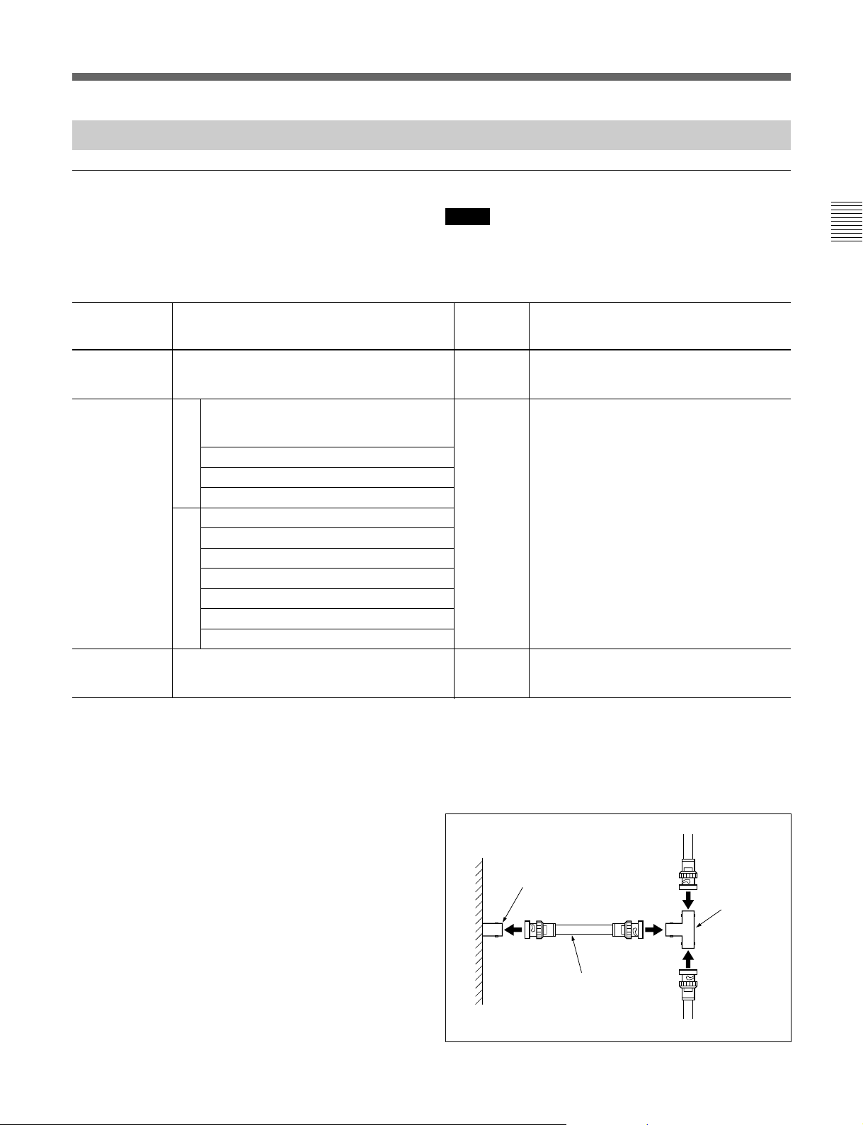
Major system components
This system are composed with S-BUS data link
connected with 75-ohm coaxial cables as its core.
The major components of the S-BUS data link are
Note
Although you may use a switcher other than the DVS128 for the primary station, some functions are limited.
listed below.
Configuration of an S-BUS data link
Description
on the S-BUS
data link Equipment Quantity Function
Primary station Routing switcher DVS-128 1 Communication control over the entire
Secondary Video routing switcher DVS-V1616 253 max. Communication control in each unit.
stations DVS-V3232B/M Each performs communication according to
DVS-V6464B/M instructions from the primary station.
Audio routing switcher DVS-A3232
Switcher
RS-422A routing switcher DVS-RS1616
Time code routing switcher DVS-TC3232
X-Y control unit BKS-R3210
32-button control unit BKS-R3209
Universal control unit BKS-R1607
16-button control unit BKS-R1608
8-destination control unit BKS-R3206
Single status display unit BKS-R3280
Remote control unit
Single status display unit BKS-R3281
Terminal Terminal simulator General PC 1 Various system settings.
S-BUS data link. Simultaneously operable
as a secondary station.
Indication and control of errors that are
generated in the S-BUS line.
Notes on connections
•Set the P/S switch on the internal CPU board of the
routing switcher to be used for the primary station to
P (or to M when the switch designation is M/S).
•Set the M/S switch on the internal CPU board of the
routing switcher (or the P/S switch if the switcher is
DVS-128) to be used for a secondary station to S.
•A maximum of 128 routing switchers and control
units can be connected to one S-BUS line.
•The coaxial cable can be extended up to 500 meters
when a BELDEN 8281 or equivalent cable is used.
•Be sure to terminate the T-bridge attached to the last
unit of the S-BUS line and the unused REMOTE 1
connectors of each switcher with 75-ohm terminators.
•Only one of the REMOTE 1 connectors can be used
on the routing switcher used for a secondary station.
•The optional BKS-R1607/R1608/R3209/R3210
control units (version 3.00 or higher) remote control
can be connected to the REMOTE 4 connector.
How to use the T-bridge (type B)
T-bridges of type B are supplied with the DVS-128.
To use them, connect as follows to coaxial cables
3
shorter than 50 cm (19
REMOTE 1 connector
(BNC, female)
BELDEN 8281 cable (less than
50 cm or 193/4 inches) or
equivalent
/4 inches):
T-bridge
(type B)
9 (E)
Page 34
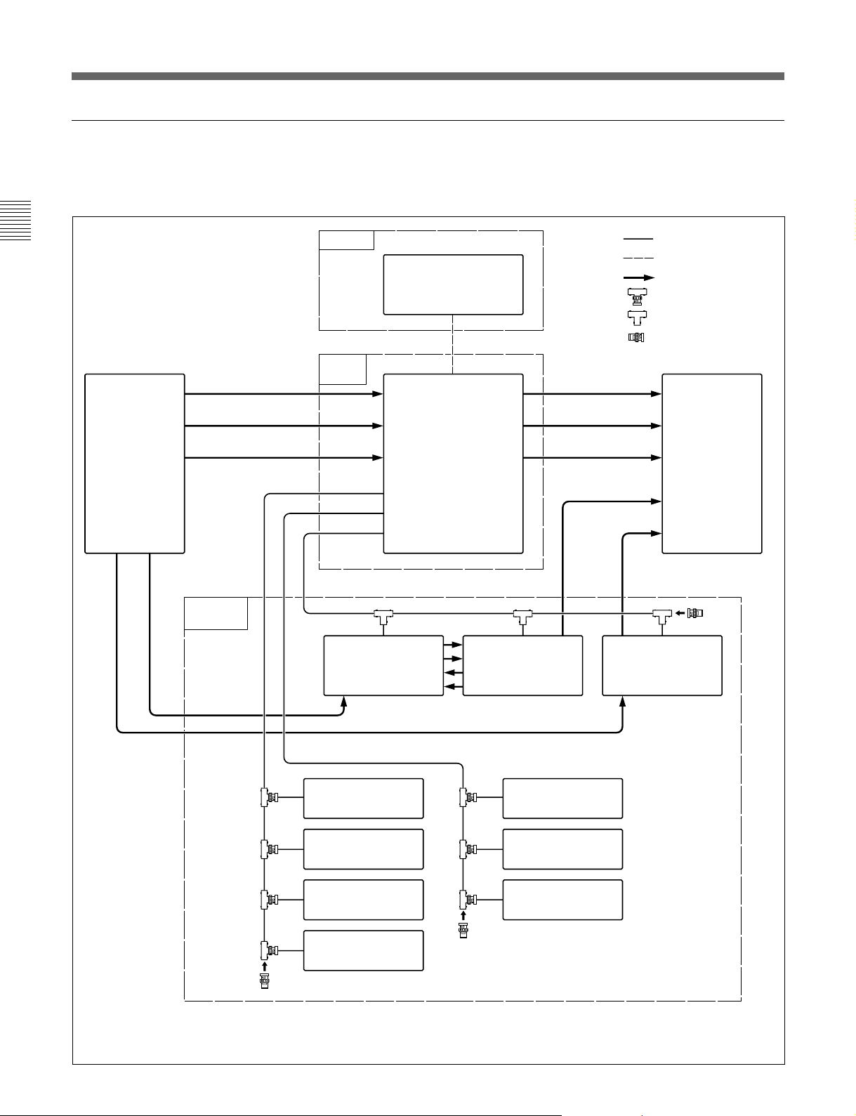
Overview
Connection example
The following diagram shows the configuration of an S-BUS
data link with the DVS-128 system as the primary station.
Source
VTR
Analog video
Analog audio
channels1/2
Analog audio
channels 3/4
Secondary
Station
Terminal
Primary
Station
REMOTE 1
Personal computer
(Terminal emulation)
REMOTE 3
Hybrid Routing Switcher
DVS-128
(P)
C
B
A
Analog video
Analog audio
channels1/2
Analog audio
channels 3/4
Digital video
Time code
: S-BUS
: RS-232C
: Signal line
: T-bridge (type A)
: T-bridge (type B)
: 75-ohm terminator
Destination
VTR
Time code
Digital video
Remote Control
Unit
BKS-R1607
Remote Control
Unit
BKS-R1608
Remote Control
Unit
BKS-R3209
Remote Control
Unit
BKS-R3210
Video
Routing Switcher
DVS-V6464M
(S)
(P): Set P/S switch on the CPU board to P (see the previous page).
(S): Set M/S switch on the CPU board to M (see the previous page).
Video
Routing Switcher
DVS-V6464M
(S)
Remote Control
Unit
BKS-R3206
Display Unit
BKS-R3280
Display Unit
BKS-R3281
Time Code
Routing Switcher
DVS-TC3232
(S)
10 (E)
Page 35

Locations and Functions of Parts
DVS-128 Routing Switcher
Front panel
1 Status indicators
2 POWER switches
1 Status indicators
Indicate the status of the DVS-128 by the color of the
indicator and whether it is lit continuously or flashing.
The indicator lights green when power is turned on
and operations are normal. When an error occurs,
either the indicator flashes green, or lights or flashes
red.
The right indicator (B) functions only when an
optional BKDS-12891 backup power supply unit is
installed.
For details on errors, see “Error Indications and
Countermeasures” on page 17(E)
2 POWER switches
Used to turn the power on and off.
The right switch (B) functions only when an optional
BKDS-12891 backup power supply unit is installed.
11 (E)
Page 36
Locations and Functions of Parts
Rear panel
3 ~AC IN receptacles
4 U terminal
5 REF IN and WORD SYNC IN
connectors A
1 Output panel slots
6 REF IN and WORD SYNC IN
connectors B
7 REMOTE 1 connectors
8 REMOTE 2 connectors
9 REMOTE 3 connector
q; REMOTE 4 connector
2 Input panel slots
1 Output panel slots
The unit accommodates a total of four optional output
boards BKDS-AA11, BKDS-AV11, or BKDS-DA11.
2 Input panel slots
The unit accommodates a total of four optional input
boards BKDS-AA10, BKDS-AV10, or BKDS-DA10.
12 (E)
3 ~AC IN (AC power input) receptacles
Connect to an AC outlet using the optional AC power
cords.
Note
The lower connector functions only when the optional
BKDS-12891 backup power supply unit is installed.
4 U (signal ground) terminal
.
Page 37

5 REF IN and WORD SYNC IN connectors A
(BNC type)
For line A inputs.
REF IN (reference video input): Accept analog
reference video signals (black burst signals
compatible with CCIR624 standards).
Two connectors have internal loop-through
connections. If loop-through output signals are
not used, put a 75-ohm terminator on any
connector that is not used.
WORD SYNC IN (audio word sync): Accept audio
word sync signals.
Two connectors have internal loop-through
connections. If loop-through output signals are
not used, put a 75-ohm terminator on any
connector that is not used.
Note
Set the S4-1 switch on the CPU-275 board to the
SYNC position if you wish to synchronize signal
switching with the reference signal. Also, set the
timing of signal switching (odd or even field) on the
PC (terminal emulator).
For further details, refer to the maintenance manual and
installation manual.
6 REF IN and WORD SYNC IN connectors B
(BNC type)
For line B inputs. The connectors function the same as
those of line A.
Switching between A and B is made on each board.
8 REMOTE 2 connectors A and B (D-sub 9-pin)
Connect an external control unit using a Sony 9-pin
remote control cable for use via the RS-422A
interface.
For further details, refer to the installation manual.
9 REMOTE 3 connector (D-sub 9-pin)
Connect an external control unit using a Sony 9-pin
remote control cable for use via the RS-232C interface.
For monitoring the operating status of this switcher
using the ISR system, connect the ISR system to this
connector.
For details on the ISR system, refer to the installation
manual.
Notes
•Set the S4-3 switch on the CPU-275 board to the
TERM position and the S4-2 switch to the P position.
For further details, refer to the maintenance manual.
•Use the D-sub 9-pin connectors with inch screws for
connections.
q; REMOTE 4 connector (BNC)
Accepts the control signals that controls monitoring of
output signals via S-BUS protocol.
The optional BKS-R1607/R1608/R3209/R3210
control units (version 3.00 or higher) remote control
can be connected to this connector.
7 REMOTE 1 connectors A, B, and C (BNC type)
Connect the remote control unit and routing switchers
using a single coaxial cable to control the system via
S-BUS protocol. When you use this switcher as the
primary station1) (set the internal P/S switch to P), a
maximum of 253 remote control units and routing
switchers can be connected to these three connectors.
1)
When you use this switcher as a secondary station
(set
the internal P/S switch to S), connect an S-BUS
link to one of the connectors using the supplied
T-bridge (type B) and put the supplied 75-ohm
terminators on the other two connectors.
See “System Connection Example” on page 9(E).
1)Remote control operations via S-BUS protocol consist of
a data link constructed using a single coaxial cable link.
Several pieces of equipment (i.e. routing switchers,
control units, etc.) are connected to this data link for data
transmission in time-sharing mode. One of the connected
switchers is used as the primary station that manages the
use of the data link, while the other equipment is used as
secondary stations which follow directions from the
primary station. The response speed may slow down due
to the number of secondary stations.
13 (E)
Page 38
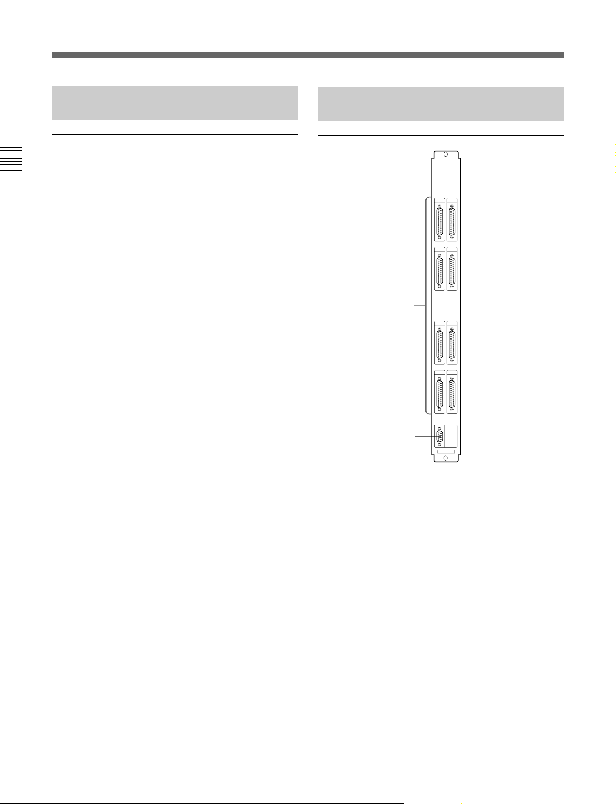
Locations and Functions of Parts
BKDS-AA10
Analog Audio Input Board
BKDS-AA11
Analog Audio Output Board
OUTPUTS
15
26
1
37
4
8
INPUTS connectors 1 to 8 (25-pin D sub, female)
For analog audio input. Each connector accepts stereo
signals of 4 channels, providing a total of 32 channel
stereo inputs on a single board.
MONITOR
2
OUT
BKDS-AA11
1 OUTPUTS connectors 1 to 8 (25-pin D sub,
female)
For analog audio output. Each connector supplies
stereo signals of 4 channels, providing a total of 32
channel stereo outputs on a single board.
2 MONITOR OUT connector (9-pin D sub)
For monitoring an analog audio output in stereo.
The output to be monitored can be selected from line
output channels 1 to 32.
14 (E)
Page 39
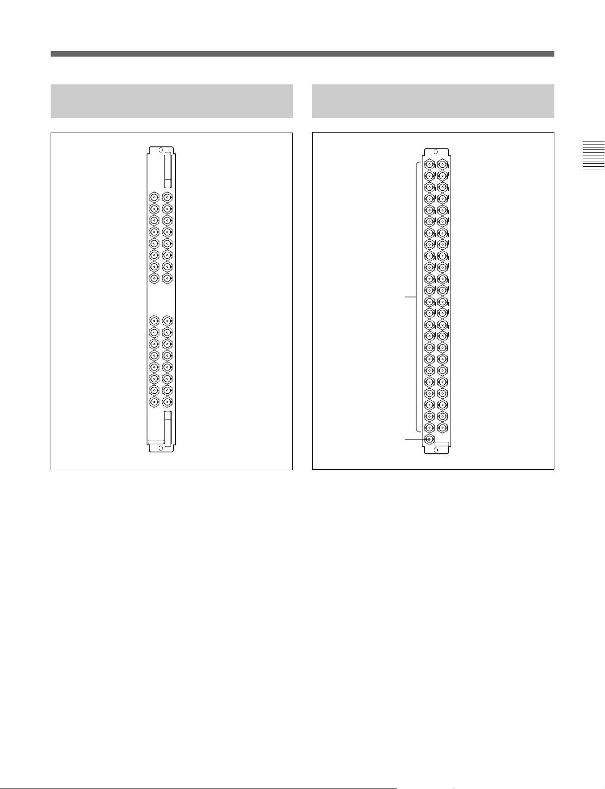
BKDS-AV10
Analog Video Input Board
BKDS-AV11
Analog Video Output Board
INPUTS
BKDS-AV10
OUTPUTS
117
117
218
319
420
521
622
723
824
218
319
420
521
622
1
32
MONITOR
OUT
BKDS-AV11
723
824
925
1026
1127
1228
1329
1430
1531
16
925
1026
1127
1228
1329
1430
1531
1632
2
INPUTS connectors 1 to 32 (BNC type)
For analog video input.
1 OUTPUTS connectors 1 to 32 (BNC type)
For analog video output.
Connectors 1 to 8 and 17 to 24 are pairs of output
connectors.
2 MONITOR OUT connector (BNC type)
For monitoring an analog video output.
The output to be monitored can be selected from line
output channels 1 to 32.
15 (E)
Page 40
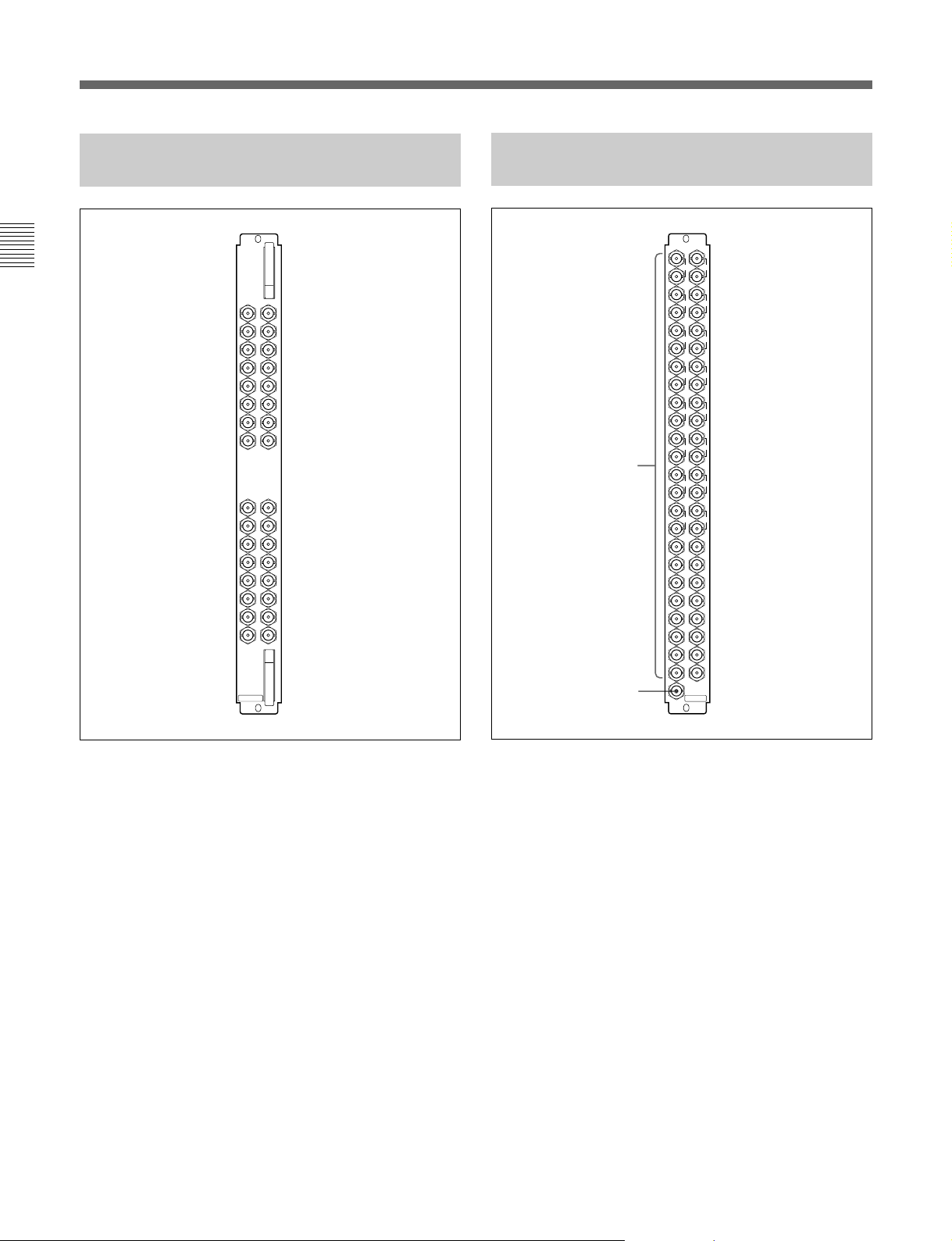
Locations and Functions of Parts
BKDS-DA10
AES/EBU Input Board
INPUTS
117
218
319
420
521
622
723
824
925
1026
1127
1228
1329
1430
1531
1632
BKDS-DA10
BKDS-DA11
AES/EBU Output Board
OUTPUTS
117
218
319
420
521
622
1
2
32
MONITOR
OUT
BKDS-DA11
723
824
925
1026
1127
1228
1329
1430
1531
16
INPUTS connectors 1 to 32 (BNC type)
For AES/EBU digital audio inputs.
16 (E)
1 OUTPUTS connectors 1 to 32 (BNC type)
For AES/EBU digital audio outputs.
Connectors 1 to 8 and 17 to 24 are pairs of output
connectors.
2 MONITOR OUT connector (BNC type)
For monitoring an AES/EBU digital audio output.
The output to be monitored can be selected from line
output channels 1 to 32.
Page 41
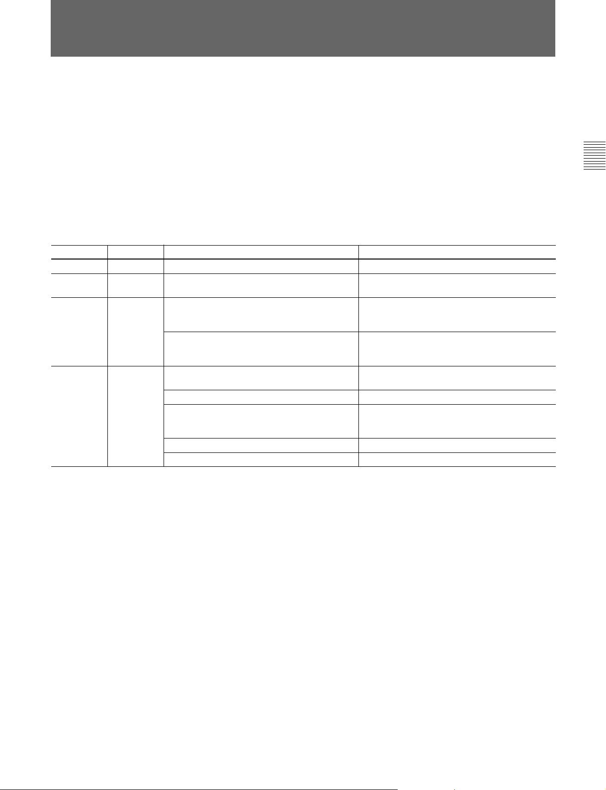
Error Indications and Countermeasures
This switcher performs self-diagnosis testing when you
turn the power on or reset the switcher, and at regular
intervals during operation. If the self-diagnosis test
detects an error, the status indicator lights, and
information about the error is output to the terminal.
The information about the error is also output to the
host computer of the ISR system if this switcher is
connected to the system.
through the 2-digit error code shown on the ERROR
No. indicator on the CPU-275 board.
The errors that may be displayed on the switcher and
their respective countermeasures are shown in the table
below.
Refer to the maintenance manual for information
concerning the error codes displayed on the ERROR No.
indicator and the appropriate countermeasures.
You can easily determine the origination of the error
Meanings of status indications and countermeasures for errors
Indicator Status Meaning
Green Lit Switcher operations are normal.
Green Flashing No sync signal detected.
Red Lit Both the standard and backup CPU boards
have been installed, but there is a problem with
one of the boards.
Both the standard and backup power supply
units have been installed, but the voltage at
one of the units is low.
Red Flashing An S-BUS data link cable is disconnected.
A 75-ohm terminator is not attached.
Crosspoint error. The result of signal existence
detection differ between input and output
connectors.
ROM or RAM error.
The fan stops working
Countermeasures
–
Supply a reference video signal to the REF IN A
connector.
Replace the defective CPU board.
Replace the defective power supply unit.
Check the device that returns no response and
re-connect it.
Attach a 75-ohm terminator.
Check the operations of the input/output boards
and replace the defective board.
Replace the CPU board.
Replace the fan unit.
17 (E)
Page 42

Specifications
DVS-128 Routing Switcher
General
Power requirements 100 to 240 V AC, 50/60 Hz
Current drain 100 V AC: 9.4 A max.
240 V AC: 3.8 A max.
Power supply capacity
Peak inrush current
(1) Power ON, current probe method:
(2) Hot switching inrush current, measured in
Operating temperature
Storage temperature –20°C to +60°C (–4°F to +140°F)
Mass Approx. 33 kg (72 lb 12 oz)
Dimensions 424 × 620 × 550 mm (w/h/d)
Mountable units
Supplied units AC power supply unit (1)
Optional units Backup power supply unit
Video sync inputs
Signals Analog video reference signal
Input connectors REF IN A/B: BNC type (2),
Input return loss 42 dB or more (DC to 5 MHz)
18 (E)
+5.6 V DC: 45 A max.
–5.6 V DC: 45 A max.
25A(240V), 25A (100V)
accordance with European
standard EN55103-1:
25A (230V)
5°C to 40°C (41°F to 104°F)
(excluding optional unit/boards)
3
/4 × 241/2 × 213/4 inches)
(16
CPU control board (1)
Backup CPU control board
Signal input boards
for analog audio
for analog video
for digital audio
(Four boards at maximum can
be mounted in combination.)
Signal output boards
for analog audio
for analog video
for digital audio
(Four boards at maximum can
be mounted in combination.)
(black burst signal) or analog HD
video (three-value sync)
reference signal.
Two inputs, A and B, available
unbalanced, with loop-through
output, high impedance
receiption (used with 75-ohm
termination)
Word sync inputs
Signal 48 kHz audio word sync
0.5 to 5 Vp-p squire wave
Two inputs, A and B, available
Input connectors WORD SYNC IN A/B:
BNC type (2), with loop-through
output, high impedance reception
(used with 75-ohm termination)
Input return loss 42 dB or more (DC to 6 MHz)
Internal sync Automatically synchronizes with
the reference signal at REF IN
connector if there is no word sync
input.
Remote control connectors
REMOTE 1 S-BUS remote connector: BNC
type (3), 47-kilohm input
Data transfer rate: 312.5/1250 kbps
Signal transfer distance: 500 m
(when using a BELDEN 8281 75-
ohm coaxial cable or equivalent)
REMOTE 2 Complies with RS-422A signal
standard (can be converted to S-
BUS commands)
D-sub 9-pin (2),
100 ohms/10 kilohms
Data transfer rate : 38.4 kbps
REMOTE 3 Complies with RS-232C signal
standard for connecting a terminal
D-sub 9-pin, male (fixed with
inch screws) (1)
Terminal 9600/38400 bps, DTR control
8 bits, no parity, no check, 1 stop
bit
ISR 9600 bps
7 bits, ODD parity, 1 stop bit
REMOTE 4 S-BUS remote connector: BNC
type (1)
Same specifications with
REMOTE 1.
For control monitor output of
output boards
Accessories supplied
Operation manual (1)
Installation manual for software (1)
Maintenance manual Part 1 (1)
75-ohm terminators (3)
T-bridge (type B) (1)
Floppy disk (BZR-20 Backup Software) (1)
Design and specifications are subject to change
without notice.
Page 43

BKDS-12890 Backup CPU Board
This board is identical to the standard CPU board built
in the DVS-128 and has the same functions and
characteristics.
General
Power requirements +5.6 V DC: 1.0 A
Power consumption Approx. 5.7 W
Operating temperature
5°C to 40°C (41°F to 104°F)
Dimensions 237 × 381 mm (h/d)
Mass Approx. 0.7 kg (1 lb 9 oz)
Accessory supplied
Operation and installation guide (1)
3
/8 × 15 inches)
(9
BKDS-AA10
Analog Audio Input Board
General
Power requirements +5.6 V DC: 2.2 A
–5.6 V DC: 1.2 A
Power consumption Approx. 19 W
Operating temperature
5°C to 40°C (41°F to 104°F)
Dimensions
Main board 440 × 381 mm (h/d)
Connector panel 41 × 467 × 102 mm (w/h/d)
Mass
Main board Approx. 1.5 kg (3 lb 5 oz)
Connector panel Approx. 0.8 kg (1 lb 12 oz)
3
/8 × 15 inches)
(17
5
/8 × 181/2 × 41/8 inches)
(1
Design and specifications are subject to change
without notice.
BKDS-12891 Backup Power
Supply Unit
This unit is identical to the standard power supply unit
built in the DVS-128 and has the same functions and
characteristics.
General
Power requirements 100 to 240 V AC, 50/60 Hz
Current drain 100 V AC: 9.4 A max.
240 V AC: 3.8 A max.
Power supply capacity
+5.6 V DC: 45 A max.
–5.6 V DC: 45 A max.
Operating temperature
5°C to 40°C (41°F to 104°F)
Dimensions 193 × 156 × 423 mm (w/h/d)
Mass Approx. 8.0 kg (17 lb 10 oz)
Accessory supplied
Operation and installation guide (1)
Design and specifications are subject to change
without notice.
5
/8 × 61/4 × 163/4 inches)
(7
Inputs
Analog audio input connectors
D-sub 25-pin, female (8)
4 channels each × stereo
Input channels 32 channels × stereo
Input impedance 600 ohms/20 kilohms (selectable
by an internal switch)
Reference input level
+4 dBm (–10 dBm to +8 dBm,
continuously variable)
Reference signal output
AES/EBU format digital
conversion output
A/D conversion characteristics
Quantization 20-bit linear/48-kHz sampling
Headroom 20 dB (at the reference level)
Frequency response 20 Hz to 20 kHz
within ±0.1 dB
(with BKDS-DA11)
+0.2
–0.3
dB
within
(with BKDS-AA11)
(both with the 1 kHz reference)
Distortion 0.05% or less
(Reference: 1 kHz, 30 kHz low
pass)
Signal-to-noise ratio 95 dB or more (with BKDS-
DA11, maximum output level,
30 kHz low pass)
90 dB or more (with BKDS-
AA11, maximum output level,
30 kHz low pass)
Crosstalk –90 dB or less (at 15 kHz or less)
19 (E)
Page 44

Specifications
Pre-emphasis Not applicable
Signal delay Approx. 0.6 ms (in use with
BKDS-DA11)
Approx. 1.0 ms (in use with
BKDS-AA11)
Reference inputs
Audio clock Synchronizes with the audio
word sync supplied to WORD
SYNC IN A or B of the DVS-128
(Switching between A and B is
made on a switch on the main
board.)
Automatically synchronizes with
the reference video at the
corresponding REF IN connector
if no audio word sync is
available.
Accessories supplied
Operation and installation guide (1)
D-sub 25-pin adaptor (8)
Design and specifications are subject to change
without notice.
BKDS-AA11
Analog Audio Output Board
General
Power requirements +5.6 V DC: 5.5 to 8.6 A
–5.6 V DC: 4.1 to 7.0 A
Power consumption Approx. 55 to 88 W (depends on
the audio output level)
Operating temperature
5°C to 40°C (41°F to 104°F)
Dimensions
Main board 440 × 381 mm (h/d)
Connector panel 41 × 467 × 102 mm (w/h/d)
Mass
Main board Approx. 2.5 kg (5 lb 8 oz)
Connector panel Approx. 0.8 kg (1 lb 12 oz)
Matrix switcher block
Input signal AES/EBU digital audio signal
Matrix size 128 inputs × 32 outputs
Switching format Reference synchronization
3
/8 × 15 inches)
(17
5
/8 × 181/2 × 41/8 inches)
(1
bus
Outputs
Analog audio output connectors
D-sub 25-pin, female (8)
4 channels each × stereo
Balanced (transformerless
electronic balance differential
output)
Output channels 32 channels × stereo
Monitor output connector
D-sub 9-pin, female (1)
Output channels 1 channel × stereo
Output impedance Approx. 20 ohms
Optimum load impedance
600 ohms
D/A conversion characteristics
Quantization 20-bit linear/48-kHz sampling
Headroom 20 dB (at reference level)
Reference output level
+4 dBm (–10 dBm to +8 dBm
continuously variable)
Maximum output level
+24 dBm
(with a 600-ohm load)
+25 dBs or more
(with a high impedance receiver)
20 (E)
Page 45

Frequency response 20 Hz to 20 kHz
within ±0.2 dB
(with BKDS-DA10 connected)
+0.2
within
–0.3
dB
(with BKDS-AA10 connected)
Distortion 0.05% or less
(Reference 1 kHz, 30 kHz low
pass)
Signal-to-noise ratio 93 dB or more (with BKDS-
DA10, maximum output level,
30 kHz low pass)
90 dB or more (with BKDSAA10, maximum output level,
30 kHz low pass)
Crosstalk –90 dB or less (at 15 kHz or less)
Signal delay Approx. 0.4 ms (with input from
BKDS-DA10)
Approx. 1.0 ms (with input from
BKDS-AA10)
Reference inputs
Audio clock 48 kHz word sync
Synchronizes with the audio
word sync supplied to WORD
SYNC IN A or B of the DVS-128
(Switching between A and B is
made on a switch on the main
board. Always select the same
one as that of the input board.)
Automatically synchronizes with
the reference video at REF IN A
or B if no audio word sync is
available.
Reference video Generates switching timing for
the matrix switcher block.
(Switching between A and B is
made on a switch on the main
board.)
BKDS-AV10
Analog Video Input Board
General
Power requirements +5.6 V DC: 1.1 A
–5.6 V DC: 0.8 A
Power consumption Approx. 11 W
Operating temperature
5°C to 40°C (41°F to 104°F)
Dimensions
Main board 440 × 381 mm (h/d)
Connector panel 41 × 467 × 102 mm (w/h/d)
Mass
Main board Approx. 1.3 kg (2 lb 14 oz)
Connector panel Approx. 1.0 kg (2 lb 3 oz)
Inputs
Analog video input connectors:
Input channels 32 channels stereo
Input signal 1 Vp-p SD/HD analog video
Input return loss 40 dB or more (DC to 5 MHz)
Signal processing
Clamp formats Self-clamp, reference clamp, or
Signal detection Sync signal level detection
Characteristics
See those of BKDS-AV11.
Accessory supplied
Operation and installation guide (1)
3
/8 × 15 inches)
(17
5
/8 × 181/2 × 41/8 inches)
(1
BNC type (32), 75 ohms,
unbalanced
signal
direct connection (independently
selectable for every 8 channels)
Accessories supplied
Operation and installation guide (1)
D-sub 25-pin adaptor (8)
Design and specifications are subject to change
without notice.
Design and specifications are subject to change
without notice.
21 (E)
Page 46

Specifications
BKDS-AV11
Analog Video Output Board
General
Power requirements +5.6 V DC: 5.0 A
–5.6 V DC: 3.5 A
Power consumption Approx. 48 W
Operating temperature
5°C to 40°C (41°F to 104°F)
Dimensions
Main board 440 × 381 mm (h/d)
Connector panel 41 × 467 × 102 mm (w/h/d)
Mass
Main board Approx. 1.4 kg (3 lb 1 oz)
Connector panel Approx. 1.1 kg (2 lb 7 oz)
Matrix switcher block
Matrix size 128 inputs × 32 outputs
Switching format Double latch, blanking switching
Outputs
Analog video output connectors
Output channels 32 channels
Monitor output connector
Output channel 1 channel
Output return loss 42 dB or more (DC to 5 MHz)
Characteristics
General performance when the BKDS-AV10 is used
for inputs.
DG 0.1% or less (4.43 MHz, 10 to
DP 0.1˚ or less (4.43 MHz, 10 to
Frequency response 100 kHz to 10 MHz within ±0.15
Crosstalk –60 dB or less (at 5 MHz)
Signal-to-noise ratio 73 dB or more (5 MHz, low pass)
Phase difference between inputs
3
/8 × 15 inches)
(17
5
/8 × 181/2 × 41/8 inches)
(1
BNC type (48), 75 ohms,
unbalanced
Two outputs each are available
for channels 1 to 8 and 16 to 24.
BNC type (1)
90% apl)
90% apl)
dB (Reference: 1 MHz)
+0.5
10 MHz to 30 MHz within
–1.3
dB
(Reference: 1 MHz)
1.5˚ or less
Switching step ±50 mV or less
Tilt 0.5% or less
K factor Less than 0.5%
Gain stability ±0.15 dB
Total delay time Approx. 32 ns
Accessory supplied
Operation and installation guide (1)
Design and specifications are subject to change
without notice.
BKDS-DA10
AES/EBU Input Board
General
Power requirements +5.6 V DC: 1.8 A
Power consumption Approx. 10 W
Operating temperature
5°C to 40°C (41°F to 104°F)
Dimensions
Main board 440 × 381 mm (h/d)
Connector panel 41 × 467 × 102 mm (w/h/d)
Mass
Main board Approx. 1.3 kg (2 lb 14 oz)
Connector panel Approx. 1.0 kg (2 lb 3 oz)
Inputs
Digital audio input connectors
Input signal format AES/EBU digital audio signal
Requirements for input signal
Input channels 32 channels stereo
Reference signal levels
Input return loss
Input characteristics
Signal transfer distance
3
/8 × 15 inches)
(17
5
/8 × 181/2 × 41/8 inches)
(1
BNC type (32), 75 ohms
ANSI S.4.40 (AES-3)
48-kHz-sampling AES/EBU
digital audio signal which
synchronizes with the reference
audio word sync
1 Vp-p
26 dB or more (0.1 MHz to 6 MHz)
600 m or more (signal source
level 1Vp-p in use of a BELDEN
8281 75-ohm coaxial cable or
equivalent)
22 (E)
Page 47

Input jitter margin ±30 ns or more
Signal delay Approx. 0.04 ms (in use with
BKDS-DA11)
Approx. 0.4 ms (in use with
BKDS-AA11)
Accessory supplied
Operation and installation guide (1)
Design and specifications are subject to change
without notice.
Output waveform
Output signal level 1 Vp-p±10% or less (with 75-
ohm termination)
DC offset Within ±50 mV
Waveform rising/falling
37±7 ns
Output jitter ±10 ns or less (50 Hz to 10 kHz
bandpath)
Signal delay Approx. 0.04 ms (with input from
BKDS-DA10)
Approx. 0.6 ms (with input from
BKDS-AA10)
BKDS-DA11
AES/EBU Output Board
General
Power requirements +5.6 V DC: 1.7 A
Power consumption Approx. 9.5 W
Operating temperature
5°C to 40°C (41°F to 104°F)
Dimensions
Main board 440 × 381 mm (h/d)
Connector panel 41 × 467 × 102 mm (w/h/d)
Mass
Main board Approx. 1.3 kg (2 lb 14 oz)
Connector panel Approx. 1.1 kg (2 lb 7 oz)
Matrix switcher block
Input signal AES/EBU digital audio signal
Matrix size 128 inputs × 32 outputs
Switching format Reference synchronization
3
/8 × 15 inches)
(17
5
/8 × 181/2 × 41/8 inches)
(1
bus
Accessory supplied
Operation and installation guide (1)
Design and specifications are subject to change
without notice.
Outputs
AES/EBU Digital audio output connectors
BNC type (48), 75 ohms,
unbalanced
Output channels 32 channels
Two outputs each are available
for channels 1 to 8 and 16 to 24.
Monitor output connector
BNC type (1)
Output channel 1 channel
Output return loss 26 dB or more (0.1 to 6 MHz)
23 (E)
Page 48

Page 49

The material contained in this manual consists of
information that is the property of Sony Corporation and is
intended solely for use by the purchasers of the equipment
described in this manual.
Sony Corporation expressly prohibits the duplication of any
portion of this manual or the use thereof for any purpose
other than the operation or maintenance of the equipment
described in this manual without the express written
permission of Sony Corporation.
Le matériel contenu dans ce manuel consiste en
informations qui sont la propriété de Sony Corporation et
sont destinées exclusivement à l’usage des acquéreurs de
l’équipement décrit dans ce manuel.
Sony Corporation interdit formellement la copie de quelque
partie que ce soit de ce manuel ou son emploi pour tout
autre but que des opérations ou entretiens de l’équipement
à moins d’une permission écrite de Sony Corporation.
Das in dieser Anleitung enthaltene Material besteht aus
Informationen, die Eigentum der Sony Corporation sind,
und ausschließlich zum Gebrauch durch den Käufer der in
dieser Anleitung beschriebenen Ausrüstung bestimmt sind.
Die Sony Corporation untersagt ausdrücklich die
Vervielfältigung jeglicher Teile dieser Anleitung oder den
Gebrauch derselben für irgendeinen anderen Zweck als die
Bedienung oder Wartung der in dieser Anleitung
beschriebenen Ausrüstung ohne ausdrückliche schriftliche
Erlaubnis der Sony Corporation.
Page 50

DVS-128 (WW, 和, 英)
3-867-319-01(2)
Sony Corporation
Broadcasting & Professional Systems Company
Printed in Japan
1999.07.13
1999
 Loading...