

Sony DVX-100-S Service manual

DVX-100S
DVD changer
Laser Semiconductor laser
Signal format system
NTSC
Audio characteristics
Frequency response
5 Hz to 20 kHz
Signal to noise ratio
90 dB
Harmonic distortion
0.01 %
Dynamic range
90 dB
Wow and flutter
below measurable limits
(±0.001 % W PEAK)
General
Outputs
Audio output
Video output
Digital output
Bus control output
Inputs
Connector of remote control sensor
Current drain
1 A (during playback)
Dimensions (approx.)
250 × 80 × 205 mm
(w/h/d) incl. projecting parts
Mass (approx.)
2.5 kg
Operating temperature
–10 ˚C to 55 ˚C
Connection adaptor
Dimensions (approx.)
105 × 26 × 45 mm (w/h/d)
Mass (approx.)
220 g
Supplied accessories
Wireless remote commander (1)
Remote control sensor (1)
Disc magazine (1)
Connection adaptor (1)
Index label (1)
Parts for installation and connections (1 set)
Design and specifications are subject to change without notice.
SERVICE MANUAL
Ver 1.1 2002.09
•DVX-100S is composed of following units.
DVD changer
Hideaway unit (XA-118)
Wireless remote commander (RM-X126)
Remote control sensor
E Model
9-874-027-02 Sony Corporation
2002I0500-1 e Vehicle Company
C 2002.09 Published by Sony Engineering Corporation
SPECIFICATIONS
DVD CHANGER
DVX-100S
NOTES ON HANDLING THE OPTICAL PICK-UP
BLOCK OR BASE UNIT
The laser diode in the optical pick-up block may suffer electrostatic break-down because of the potential difference generated
by the charged electrostatic load, etc. on clothing and the human
body.
During repair, pay attention to electrostatic break-down and also
use the procedure in the printed matter which is included in the
repair parts.
The flexible board is easily damaged and should be handled with
care.
NOTES ON LASER DIODE EMISSION CHECK
Never look into the laser diode emission from right avove when
checking it for adustment. It is feared that you will lose your sight.
NOTES ON HANDLING THE OPTICAL PICK-UP BLOCK .
The laser diode in the optical pick-up block may suffer electrostatic break-down easily. When handling it, perform soldering
bridge to the laser-tap on the flexible board. Also perform measures against electrostatic break-down sufficiently before the operation. The flexible board is easily damaged and should be handled
with care.
Notes on chip component replacement
•Never reuse a disconnected chip component.
• Notice that the minus side of a tantalum capacitor may be damaged by heat.
Flexible Circuit Board Repairing
•Keep the temperature of the soldering iron around 270 ˚C during repairing.
• Do not touch the soldering iron on the same conductor of the
circuit board (within 3 times).
• Be careful not to apply force on the conductor when soldering
or unsoldering.
laser-tap
OPTICAL PICK-UP FLEXIBLE BOARD
SAFETY-RELATED COMPONENT WARNING!!
COMPONENTS IDENTIFIED BY MARK 0 OR DOTTED
LINE WITH MARK 0 ON THE SCHEMATIC DIAGRAMS
AND IN THE PARTS LIST ARE CRITICAL TO SAFE
OPERATION. REPLACE THESE COMPONENTS WITH
SONY PARTS WHOSE PART NUMBERS APPEAR AS
SHOWN IN THIS MANU AL OR IN SUPPLEMENTS PUBLISHED BY SONY.
2

TABLE OF CONTENTS
1. SERVICING NOTES............................................... 4
2. GENERAL ................................................................... 9
3. DISASSEMBLY
3-1. Disassembly Flow ........................................................... 13
3-2. Cabinet Assy.................................................................... 14
3-3. Front Panel Assy ............................................................. 14
3-4. MPEG Board ................................................................... 15
3-5. MAIN Board ................................................................... 15
3-6. Mechanism Deck............................................................. 16
3-7. Top Chassis Assy ............................................................ 16
3-8. DC Motor Assy (Elevator) (M1)..................................... 17
3-9. Mechanism Panel Assy, Elevator Section....................... 17
3-10. DC Motor Assy (Loading) (M3)..................................... 18
3-11. CD Board......................................................................... 18
3-12. DVD Chassis Assy .......................................................... 19
4. ASSEMBLY
4-1. Adjusting Phase of A Slide Plate, B Slide Plate,
C Slide Plate and D Slide Plate ...................................... 20
DVX-100S
5. ELECTRICAL ADJUSTMENTS......................... 21
6. DIAGRAMS
6-1. Block Diagram – SERVO Section – .............................. 23
6-2. Block Diagram – VIDEO/AUDIO Section – ................ 24
6-3. Block Diagram – MAIN Section – ................................ 25
6-4. Block Diagram – CONTROL/POWER Section –......... 26
6-5. Note for Printed Wiring Boards
and Schematic Diagrams ................................................ 27
6-6. Printed Wiring Boards – SERVO Section – .................. 28
6-7. Schematic Diagrams – SERVO Section – ..................... 29
6-8. Printed Wiring Board – MAIN Board (Side A) – ......... 30
6-9. Printed Wiring Board – MAIN Board (Side B) – ......... 31
6-10. Schematic Diagram – MAIN Section (1/4) –................ 32
6-11. Schematic Diagram – MAIN Section (2/4) –................ 33
6-12. Schematic Diagram – MAIN Section (3/4) –................ 34
6-13. Schematic Diagram – MAIN Section (4/4) –................ 35
6-14. Printed Wiring Board
– MPEG Board (Component Side) –.............................. 36
6-15. Printed Wiring Board
– MPEG Board (Conductor Side) –................................ 37
6-16. Schematic Diagram – MPEG Section (1/4) – ............... 38
6-17. Schematic Diagram – MPEG Section (2/4) – ............... 39
6-18. Schematic Diagram – MPEG Section (3/4) – ............... 40
6-19. Schematic Diagram – MPEG Section (4/4) – ............... 41
6-20. IC Pin Function Description ........................................... 45
7. EXPLODED VIEWS
7-1. Front Panel, Cabinet Section .......................................... 48
7-2. MPEG Board Section...................................................... 49
7-3. Bottom Lid Section ......................................................... 50
7-4. Mechanism Deck (Top Chassis Section) ........................ 51
7-5. Mechanism Deck (Front Plate, Slide Plate Section) ...... 52
7-6. Mechanism Deck (Base Chassis Section) ...................... 53
7-7. Mechanism Deck (DVD Chassis Section) ..................... 51
7-8. Mechanism Deck (Elevator Chassis Section) ................ 55
7-9. Mechanism Deck (Clamp Chassis Section) ................... 56
8. ELECTRICAL PARTS LIST ............................... 57
3

DVX-100S
k
l
SECTION 1
SERVICING NOTES
TEST DISC
This set can playback a CD-R, CD-RW for audio use and DVD.
When test this set, use the following test disc.
Test disc for CD-R: TCD-R082LMT (Part No.: J-2502-063-1)
Test disc for CD-RW: TCD-W082L (Part No.: J-2502-063-2)
Test disc for DVD:
NTSC:
HLX-504 (Part No.: J-6090-088-A) (single layer)
HLX-505 (Part No.: J-6090-089-A) (dual layer)
PAL:
HLX-506 (Part No.: J-6090-077-A) (single layer)
HLX-507 (Part No.: J-6090-078-A) (dual layer)
DISC MAGAZINE GETTING OUT PROCEDURE
ON THE POWER SUPPLY IS OFF
Remove the CABINET ASSY, FR ONT P ANEL ASSY, MPEG
BOARD and MECHANISM DECK beforehand.
(Refer to DISASSEMBLY 3-2 to 3-4 and 3-6.)
1) Press the lock lever assy in the direction of arrow A.
2) Removal the magazine assy in the direction of arrow B.
Note: Take out the magazine only when the tray is completely within the
magazine. If the disk or tray is sticking out, turn on the power and
eject the magazine.
lock lever assy
mechanism dec
A
B
magazine assy
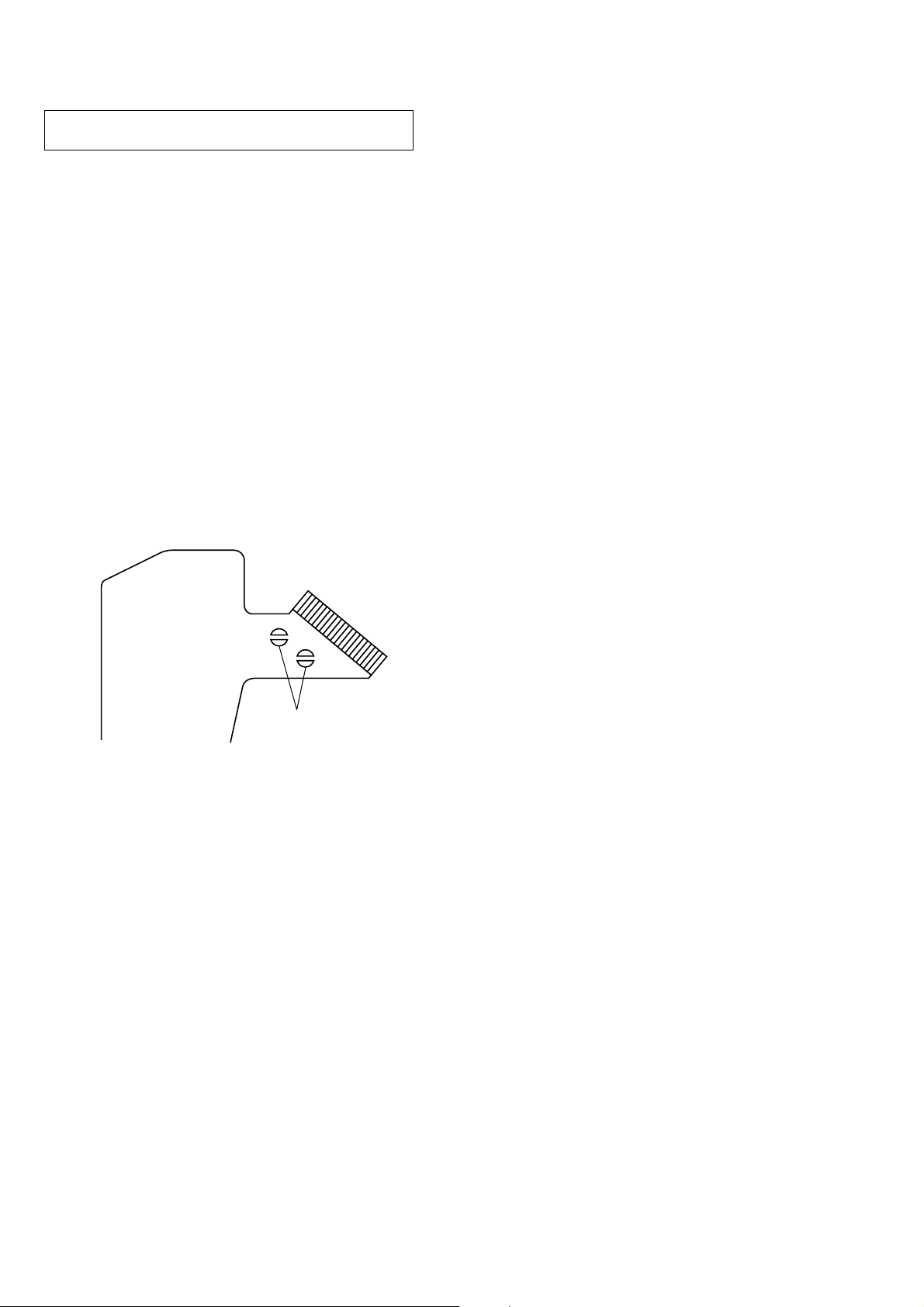
NOTE FOR TRANSPORTING A SET
When a set is transporting after service is completed, be sure to
put the caution label (9-885-016-81) on the bottom of the set and
fix it with three special screw fixers (9-885-016-80).
Note: Seals may be attached on the holes for special screw fixers.
Remove them completely, then install special screw fixers.
special screw fixer
caution labe
bottom
seal
DVD changer
4
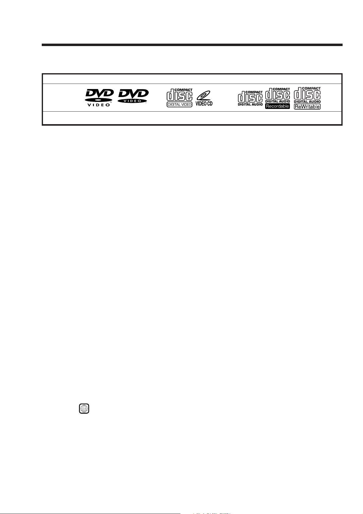
This Unit Can Play the Following Discs
DVX-100S
DVD VIDEOs
Disc logo
Contents
The “DVD VIDEO” logo is a trademark.
DVD
A DVD disc contains both audio and visual data. A 12
centimetre disc can hold 7 times the amount of data
contained in a CD-ROM, which translates to 4 consecutive
hours of playing time (8 hours for double-sided discs).
DVD discs are divided into 4 types: single sided single
layer, single sided double layer, double sided single layer,
and double sided double layer.
Video CD
A Video CD can contain both audio and visual data on a
disc the same size as a regular Audio CD. The playing
time is 74 minutes for a standard 12 centimetre CD.
Audio CD
An Audio CD containing audio data. The playing time is
74 minutes for a standard 12 centimetre CD.
CD-Recordable (CD-R) for audio use
With a CD-R for audio use, you can edit audio data. You
can write information on a CD-R only once.
CD-Rewritable (CD-RW) for audio use
With a CD-RW for audio use, you can edit audio data. You
can write information on a CD-RW again and again.
CD-Extra
A CD-Extra has two sections containing audio and data.
You can only play the section of audio on this unit.
Mixed CD
A Mixed CD has one section containing both audio and
data. You can only play the part of audio on this unit.
Audio + Video Audio + Video
Video CDs Audio CDs
Audio
Note on the TV colour systems
The colour system differs, depending on your country.
— Your DVD changer conforms to the NTSC colour
system. You cannot play discs recorded in other
colour systems such as SECAM and PAL.
Caution
• You can play CD-Rs and CD-RWs designed for audio
with this unit, however, depending on the recorded
conditions, you can’t play some discs.
• You CANNOT play these discs on this unit.
— DVD-Audio — DVD-RAM
— DVD-ROM — 8 cm discs
— DVD-RW — DVD-R
— Active-Audio (Data) — CD-G
— Photo-CD — VSD
— CD-Extra (Data) — MixedCD (DATA)
— CD-ROM
• This product incorporates copyright protection
technology that is protected by method claims of certain
U.S. patents and other intellectual property rights
owned by Macrovision Corporation and other rights
owners. Use of this copyright protection technology
must be authorized by Macrovision Corporation, and is
intended for home and other limited viewing uses only
unless otherwise authorized by Macrovision
Corporation. Reverse engineering or disassembly is
prohibited.
Region code of DVDs you can play on this unit
Your DVD changer has a region code printed on the back
of the unit and will only play DVDs that are labelled with
identical region codes.
DVDs labelled
If you try to play any other DVD, the message “This disc
can’t be played.” will appear on the screen.
Depending on the DVD, the region code indication may
not appear even if the DVD is prohibited by area
restrictions.
ALL
will also play on this unit.
5

DVX-100S
This Unit Can Play the Following Discs
Note on PBC (Playback Control) (Video CDs)
This player conforms to Ver. 1.1 and Ver. 2.0 of Video CD
standards. You can enjoy two kinds of playback according to the
disc type.
Disc type
Video CDs without
PBC functions
(Ver. 1.1 discs)
Video CDs with
PBC functions
(Ver. 2.0 discs)
You can
Enjoy video playback (moving
pictures) as well as music.
Play interactive software by using
menu screens displayed on the monitor
(PBC Playback), in addition to the
video playback functions of Ver. 1.1
discs. Moreover, you can play highresolution still pictures if they are
included on the disc.
Note on DTS-encoded CDs
When playing DTS*-encoded CDs, excessive noise will be heard
from the analog stereo outputs. To avoid possible damage to the
audio system, the consumer should take proper precautions
when the analogue stereo outputs of this DVD changer are
connected to an amplification system. To enjoy DTS Digital
Surround™ playback, an external 5.1-channel DTS Digital
Surround™ decoder system must be connected to the digital
output of this DVD changer.
* “DTS,” “DTS Digital Surround” and “DTS Digital Out” are
trademarks of Digital Theater Systems, Inc.
Note on CD-R/CD-RW
You can play certain CD-Rs and CD-RWs designed for audio use
(provided the quality of the recording is adequate).
— You can play Digital Audio CD-Rs and CD-RWs bearing
these icons:
— You CANNOT play (non-digital audio) CD-Rs and CD-RWs
bearing these icons:
6

CHUCKING OPERATION CHECKING
After the disc chucking, the following operation is performed in
this order.
1. Optical pick-up moves to the most-inside track
2. Laser diode ON
3. Disc type check
4. Focus search
5. Disc data is read
• Description of Each Operation
1. T he optical pick-up moves to ward inside until the limit switch
transition “H” → “L” is detected.
2. When the optical pick-up moved to the most-inside track, the
laser beam is emitted to check the disc type.
First, the laser diode for DVD turns on to emit a red laser beam.
(Never make an access to see the laser beam. Also, the laser
beam for CD is not visible)
When the laser beam is emitted, the voltage is applied between
the CS101 pin 8 (LDAD VD) or pin ws (LDA CD) on the MAIN
board and CS101 pin 5 (5VA1) on the MAIN board.
(DVD: approx. 300 mV, CD: approx. 500 mV)
DVX-100S
Fig. 2
3. F or the disc type check operation, refer to the wav eform shown
below (Fig.1: DVD, Fig. 2: CD, Fig. 3: CD-RW). Each figure
shows FAO, FE, and LVL waveforms from the top. The reference is VRD.
FAO w aveform (between IC102 pin 5 (FAO) on the MAIN
board and IC101 pin 8 (VRD) on the MAIN board) :
Output from the optical pick-up to the focus coil
FE waveform (between IC101 pin ef (FEO) on the MAIN
board and IC101 pin 8 (VRD) on the MAIN board) :
Signal from the optical pick-up when the object lens focus
accesses to the record surface or disc surface
LVL waveform (between IC101 pin ea (LVL) on the MAIN
board and IC101 pin 8 (VRD) on the MAIN board) :
Level of reflected beam when laser beam is radiated on the
record surface or disc surface
Fig. 3
By moving up or down the object lens of the optical pick-up at
constant speed, the FE waveform of the record surface or disc sur face can be got.
Fig. 1 to Fig. 3 show the waveforms when the focus servo turned
on normally. As the recor d surface position of the CD and CD-R W
is different from that of DVD , the FE wa v eform of the record sur face may not be outputted.
Fig. 1
7
DVX-100S
p
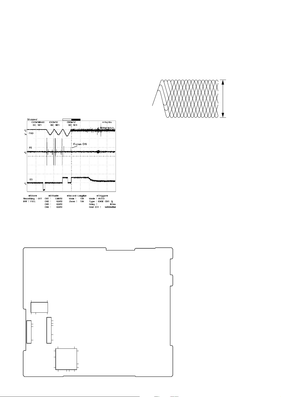
4. As for the focus search, the object lens approaches to the disc,
and when the FE of the record surface is got, the servo turns
on to activate the focus. The disc is rotated a little before the
focus search. For the signal that rotates the disc, refer to the
EC waveform (third graph from the top) in Fig. 4. The disc
rotates in the reverse direction (brake) on the minus side from
the reference voltage (VDR), or it rotates forward on the plus
side.
After the focus ON, the disc is accelerated up to the specified
constant speed, and after automatic adjustment finished, the
disc information is read.
EC waveform (betw een CS102 pin 5 (EC) on the MAIN
board and IC101 pin 8 (VRD) on the MAIN board) :
Output from the optical pick-up to the focus coil
5. After the focus ON, when automatic adjustment finished, the
RF waveform as shown in Fig. 5 is outputted. The disc data
cannot be read unless this waveform is outputted normally.
RF waveform (between IC101 pin rg (RFO) on the MAIN
board and IC101 pin 8 (VRD) on the MAIN board) :
Output from the optical pick-up to the focus coil
50mV/DIV, 50ns/DIV
Vp-
Fig. 5
Vp-p value:
DVD disc : approx. 2V
CD disc : approx. 2.5V
CD-RW disc : approx. 1.5V
Connecting Location:
– MAIN BOARD (Side A) –
1428
IC102
15
1
5
CS102
25
8
CS101
1
8
20
Fig. 4
1
5
8
22
30
80 61
IC101
34
60
45
41
403121
8

Location of controls
Wireless remote commander
SECTION 2
GENERAL
DVX-100S
This section is extracted from
instruction manual.
Light emitter
1
2
3
4
5
6
7
8
9
0
STOP ANGLE
PLAY PAUSE MENU LIST
SCAN
PREV NEXT
DISC
123
456
789
CLEAR
SUB TITLE
SEARCH
RETURN PLAY MODE
0
AUDIO
ENTER
REPEAT
A B
O
SET UP
TIME
TITLE
qa
qs
qd
qf
qg
qh
qj
qk
ql
w;
wa
ws
8
9

DVX-100S
1 ANGLE button
Press ANGLE to select the pictures of a scene viewed
from the multiple angle during a DVD playback.
2 STOP x button
Press STOP to stop playback.
3 PAUSE X button
Press PAUSE to pause playback.
4 PLAY N button
Press PLAY to play a disc.
5 SCAN buttons
Press M for fast forward playback.
Press m for fast rewind playback.
•DVD/Video CD
Press X (PAUSE), then press M/m for slow
playback.
6 PREV/NEXT button
Press > to go to the next chapter, track, or scene.
Press . to go back to the previous chapter, track or
scene.
•DVD/Video CD
Press X (PAUSE), then press > to play pictures
frame by frame.
7 DISC (+/–) buttons
Press + or – to select your favorite disc.
8 Number buttons
Press the number buttons to input numbers.
9 CLEAR button
Press CLEAR to clear the wrong number you entered.
0 RETURNO button
Press RETURN to come back to the normal playback
mode.
qa SUB TITLE button
Press SUBTITLE to change the subtitle languages
while playing a DVD.
qs AUDIO button
•DVD
Press AUDIO to change the Audio Language.
•Video CD/Audio CD
Press AUDIO to change the Audio Output Method.
qd MENU button
Press MENU to display the recorded DVD and Video
CD menu.
qf LIST button
Press LIST to display the list of discs contained in the
magazine.
qg ENTER/V/b/v/B button
Press ENTER to execute the items or settings or to
select the items.
qh SEARCH button
Press SEARCH to specify a desired point on a disc by
title, chapter, track , or time.
qj TITLE button
Press TITLE to display the title menu.
qk TIME button
Press TIME to display the elapsed/remaining time of
items such as title, chapter, track, and disc.
ql REPEAT button
• DVD
Press REPEAT to play a title or a chapter repeatedly.
•Video CD/Audio CD
Press REPEAT to play the entire tracks of a disc or a
track.
w; AyB (A-B repeat) button
• DVD/Video CD
Press AyB to play your favorite scene repeatedly.
• Audio CD
Press AyB to play your favorite passage of songs.
wa PLAY MODE button
• Audio CD
Press PLAY MODE to select your favorite playback
mode.
ws SET UP button
Press SET UP when you want to change the settings,
such as DVD Menu Language, Audio Language,
Subtitle Language, and so on.
Caution
When you want to turn on the unit, select this unit at the
master unit. Refer to the Operating Instructions of the
master unit for details.
10
9
DVX-100S
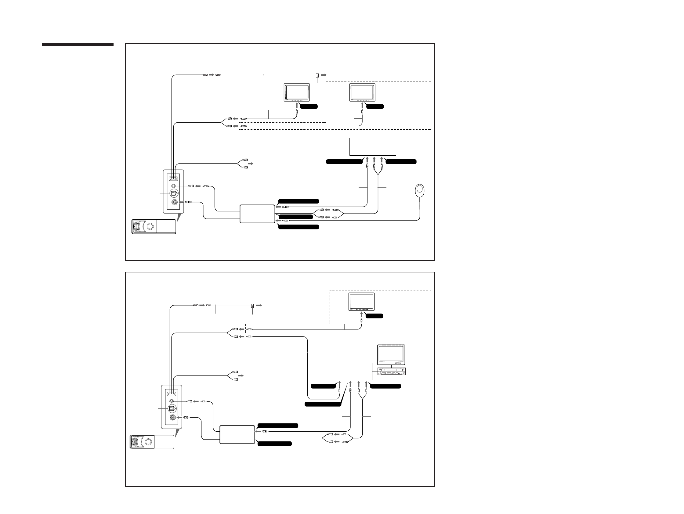
Connection diagram (2 A and B)
The audio out connections on this unit can be
configured several ways. Refer to the
corresponding number illustration above.
A
For audio out from TV/monitor speakers.
Connect RCA pin cord to the TV/monitor audio
input.
B
For audio out from digital amplifier or audio device
Connect optical cable RC-97/98 (optional) etc. to a
digital amplifier or audio device equipped with a
Dolby digital decoder.
•When making connections, be sure to connect
each cable securely.
•When wishing to connect another CD/MD
changer, use the Sony Source Selector XA-C30
(available separately). (2 A/B)
•The signals from the remote commander of this
unit can be received by the sensor of the A/V
center. (2 B)
• The supplied remote control sensor is not used in
the connection example 2. (2 B)
If the supplied remote control sensor wd is
connected to the connection adaptor, the A/V
center cannot receive signals from the remote
commander of this unit. (2 B)
2
A
Example 1
B
Side of the DVD changer
DVD changer
Light green
20 cm
20 cm
20 cm
20 cm
30 cm
VIDEO OUTPUT FRONT
Yellow
VIDEO OUTPUT REAR
Yellow
10 cm
5 m
Red
A
White
ws
Connection adaptor
XA-118
Light green
2
To parking brake swich cord
w;
Monitor
wa
1
*
qk
6 m
RCA pin cord
BUS CONTROL INPUT
*
1
Monitor
*
VIDEO INVIDEO IN
1
*
Sony bus compatible master
unit or Source Selector
when connecting second
monitor for the rear seat
BUS AUDIO INPUT
5 m5 m
Remote control
sensor
qj ql
3
BUS CONTROL OUTPUT
15 cm
BUS AUDIO OUTPUT
Remote SENSOR input
*
1
Not supplied
*
2
See “Connecting the parking brake cord” on the reverse side for details.
*
3
Match the v mark of the bus cable with the V mark of the connection adaptor.
*
wd
5 m
2
B
Example 2
B
Side of the DVD changer
DVD changer
Light green
20 cm
20 cm
20 cm
20 cm
30 cm
5 m
w;
VIDEO OUTPUT REAR
Yellow
VIDEO OUTPUT FRONT
Yellow
10 cm
ws
Connection adaptor
XA-118
Red
White
Light green
wa
A
To parking brake swich cord
BUS CONTROL OUTPUT
15 cm
BUS AUDIO OUTPUT
Second
1
monitor
2
*
RCA pin cord
*
VIDEO IN
1
*
qk
6 m
Connection box
VIDEO INPUT
BUS CONTROL INPUT
5 m 5 m
BUS AUDIO INPUT
qj ql
3
*
1
Not supplied
*
2
See “Connecting the parking brake cord” on the reverse side for details.
*
3
Match the v mark of the bus cable with the V mark of the connection adaptor.
*
when connecting second
monitor for the rear seat
A/V center
DISC
VOL
OFF
OPEN/
CLOSE
SOURCE MODE ATT
SEEK
1111
DVX-100S
3
0
8
A
H
°
5
4
H
5°
4
V
V
°
H
V
45
H
V
45°
qa
0
Horizontal installation: “H”
45º installation: “45º”
x
Foot brake type Hand brake type
4
Parking brake switch
cord
8
Vertical installation: “V”
V
5°
H
4
V
5°
H
4
7
1
5
H
5°
4
H
V
Suspended installation: “H”
5
4
°
V
B-2
Parking brake switch cord
Horizontal installation Vertical installation
B-1
8
6
7
Example: Horizontal installation
7
Carpet
1
Using the tap
wa
8
7
2
5
6
B-3
8
Parking brake switch cord
c
w;
8
7
3
5
6
7
Example: Horizontal installation
8
B-4
5
ws
qh
45° installation
8
7
8
4
3
7
5
qh
5
6
7
6
7
Example: Horizontal installation
7
B-5
8
6
qg
Back of the wireless remote commander
8
8
7
4
5
6
C-2 C-3
8
C-1
7
Light sensor
Suspended installation
7
1
ø3.5 mm
Light sensor
15º
15º
Almost 3 m
Wireless remote
commander
77
Remote control sensor
wd
qf
c
7
2
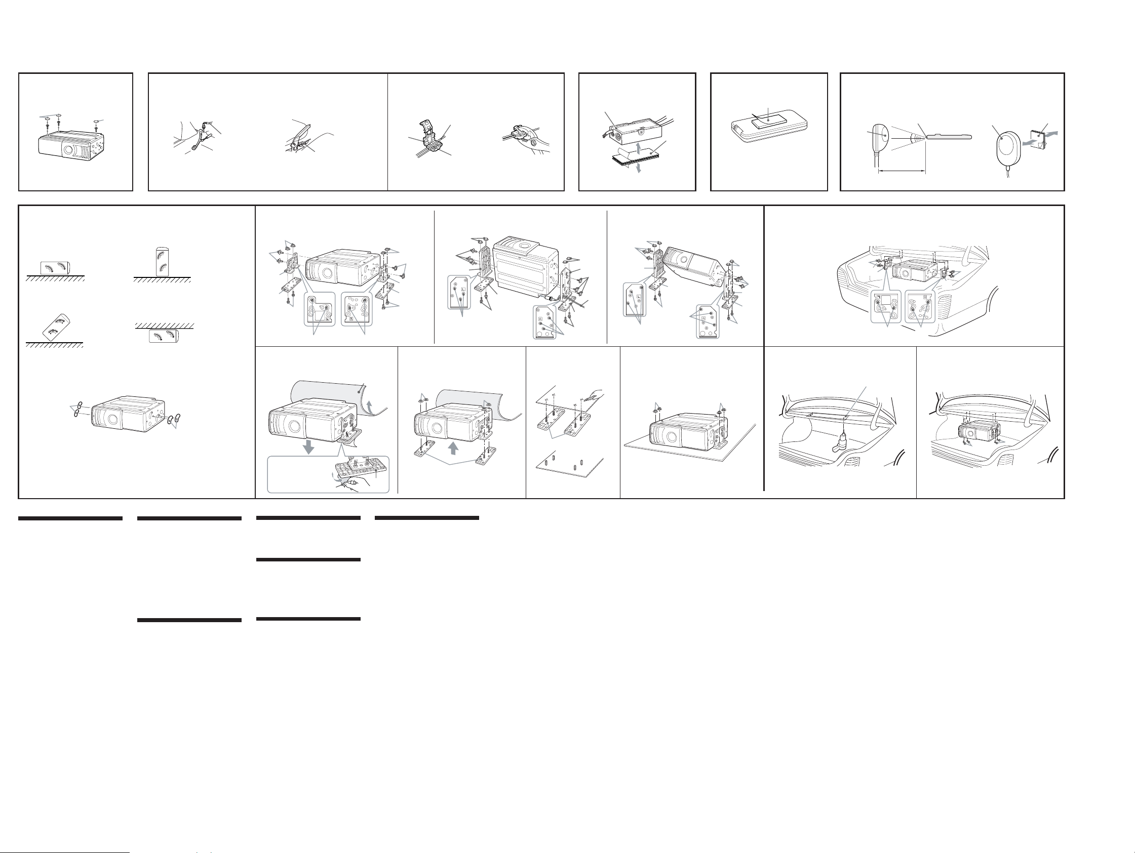
Precaution
• Choose the mounting location carefully,
observing the following:
— Do not install the unit where;
• the ambient temperature exceeds
55 °C.
• it will be exposed to direct sunlight or
hot air from a heater.
• it will be exposed to rain, water, or
high humidity.
• it will be exposed to a lot of dust.
• it will be subject to excessive
vibration.
— The fuel tank should not be damaged
by the tapping screws.
— There should be no wire harnesses or
pipelines under the place where you are
going to install the unit.
— The spare tyre, tools or other equipment
in or under the trunk should not be
interfered with or damaged by the
screws or the unit itself.
Notes
• Be sure to use only the supplied mounting
hardware for a safe and secure installation.
• Make holes of ø3.5 mm only after making sure
there is nothing on the other side of the
mounting surface.
qa
Removing the screws (3)
• On the bottom of this unit are three screws
for shipping purpose only. Be sure to
remove them before installing.
• Place the seals 0 over any holes not used
for installation and the three screws used
for shipping. These seals help to prevent
dust building up, which could cause a
malfunction.
Note
Keep the three screws for shipping purpose. Do
not lose them.
Connecting the parking brake
cord (4)
Be sure to connect the parking cord w; (light
green) to the parking brake switch cord. The
mounting position of the parking brake
switch cord depends on your car. Please
consult your car dealer or your nearest Sony
dealer for further details.
Using the tap
Attach the tap wa to the end of the parking
cord w; (light green) and the parking brake
switch cord.
Note
If the parking brake switch cord is too thin, it
may cause loose connection.
3
2
Place the seal qs.
qs
Connection adaptor (5)
Wipe the installation surface clean and use
surface fastener qh to attach the unit.
Wireless remote commander
( 6)
Wipe the installation surface clean and attach
surface fastener qg. Be sure to install it in a
position that will not interfere with driving.
Remote control sensor (7)
•Before installing the remote control sensor,
confirm the maximum signal distance of
remote control. The remote control can be
used up to approximately 3 m from the
light sensor, in a conical area spreading
roughly 15º from the light sensor.
•Wipe the installation surface clean and
attach surface fastener qf. Be sure to install
it in a position that will not interfere with
driving.
•If necessary, secure the remote control
sensor cord with the cord clamp qd.
R
5
Remove the DVD changer.
How to install the DVD
changer (8)
When you install the DVD changer, be
careful not to damage wiring or equipment
on the other side of the mounting surface.
Before installing the DVD changer (8
A)
•Before installing this unit, set the built-in
anti-vibration board as illustrated,
depending on the angle.
•After setting the angle, place the seals qa
over any holes on the side of this unit.
These seals help to prevent dust building
up, which could cause a malfunction.
Note for vertical installation (8 B-1)
Before installing in the vertical position, pass
the cable of ws through the hole at the lower
left of the bracket 4.
When the unit is to be installed under
the rear tray or in the trunk, observe
the following. (8 C)
•Choose the mounting location carefully so
that the unit can be installed horizontally.
•Make sure the unit does not hinder the
action of the torsion bar spring, hinge, etc.
of the deck lid.
Note
Make installation holes in the rear dash, after
making sure there is nothing obstructing.
5
x
9
9
5
1212

• This set can be disassembled in the order shown below.
3-1. DISASSEMBLY FLOW
Note 1: The process described in can be performed in any order.
Note 2: Without completing the process described in , the next process can not be performed.
SET
3-2. CABINET ASSY
(Page 14)
DVX-100S
SECTION 3
DISASSEMBLY
3-3. FRONT PANEL ASSY
(Page 14)
3-5. MAIN BOARD
(Page 15)
3-7. TOP CHASSIS ASSY
(Page 16)
3-8. DC MOTOR ASSY
(ELEVATOR) (M1)
(Page 17)
3-4. MPEG BOARD
(Page 15)
3-6. MECHANISM DECK
(Page 16)
3-9. MECHANISM PANEL ASSY,
ELEVATOR SECTION
(Page 17)
3-10. DC MOTOR ASSY
(LOADING) (M3)
(Page 18)
3-11. CD BOARD
(Page 18)
3-12. DVD CHASSIS ASSY
(Page 19)
13

DVX-100S
y
Note: Follow the disassembly procedure in the numerical order given.
3-2. CABINET ASSY
1
four screws
(BTT2.6 × 5)
1
screw
(BTT2.6
×
4
5)
claw
4
four claws
4
3
two bosses
claw
4
1
screw
(BTT2.6 × 5)
5
cabinet ass
two claws
3-3. FRONT PANEL ASSY
2
two claws
3
front panel assy
2
three claws
14
1
three claws
2
two claws
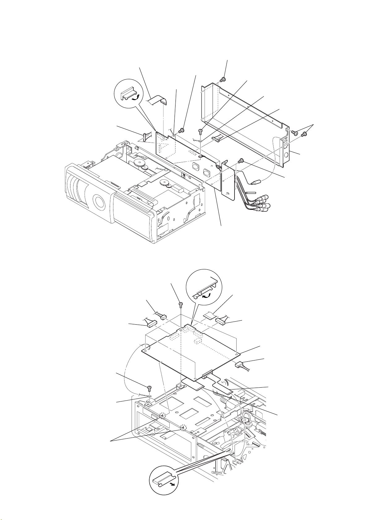
3-4. MPEG BOARD
)
4
10P 180 mm harness wire
(CS553)
3
40P-120 mm wire
(CS551)
8
7
four screws
(BTT2.6
lug assy
DVX-100S
1
two screws
(BTT2.6
×
5)
×
5
5)
screw
(PTT2
×
6
4)
lug assy
4
10P 180 mm harness wire
(CS552)
2
rear chassis assy
5
two screws
(BTT2.6
1
two screws
(BTT2.6
×
5)
×
5)
3-5. MAIN BOARD
9
10P 180 mm harness wire
(CS301)
1
screw (M2 × 4)
2
ground wire
8
pressure welding cord
(2P-160 mm) (CS303)
5
four screws
(BTT2
9
MPEG board
×
4)
7
40P-102 mm harness wire
(CS201)
9
10P 180 mm harness wire
(CS202)
qa
main board
0
pressure welding cord (5P-100 mm
(CS302)
3
25P-91 mm wire
(CS6)
6
two claws
4
30P-117 mm wire
(CS7)
15
DVX-100S
)
3-6. MECHANISM DECK
1
screw
(BTT2.6
3
two cushions
4
two dampers
7
mechanism deck
×
5)
2
PCB bracket-E
5
damper TENS spring
6
R damper TENS spring
3-7. TOP CHASSIS ASSY
3
top chassis assy
2
lug assy
5
damper TENS spring
1
screw
×
4)
(M2
6
R damper TENS spring
1
two screws
×
4)
(M2
2
1
screw (BTT2.6 × 5
4
two dampers
3
two cushions
lug assy
16

3-8. DC MOTOR ASSY (ELEVATOR) (M1)
0
front panel assy
6
ELEV TENS spring
3
ELEV TENS spring
3
ELEV TENS spring
8
elevator plate
5
elevator plate
9
screw (M2 × 4)
9
two screws (M2 × 4)
7
ring E 2.5
4
ring E 2.5
5
elevator plate
4
ring E 2.5
qs
two B sleeves
qs
B sleeve
qa
elevator section
2
mechanism panel assy
1
four special screws
1
special washer mount-M
2
B gear
5
two screws
×
2.5)
(M2
3
special washer mount-M
4
A gear
pressure welding cord
(5P-100 mm)
6
Remove two elevator motor lead wire
solders of pressure welding cord.
DVX-100S
7
DC motor assy (elevator) (M1)
3-9. MECHANISM PANEL ASSY, ELEVATOR SECTION
17

DVX-100S
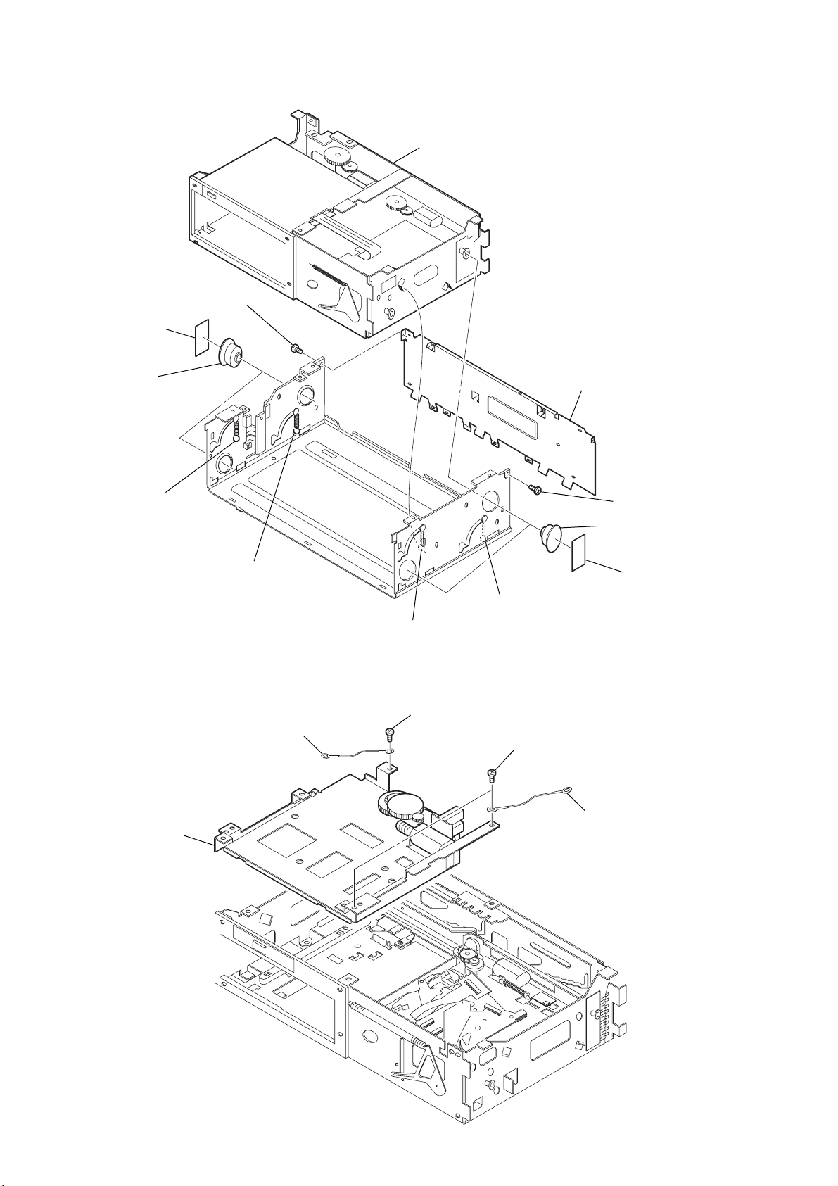
3-10. DC MOTOR ASSY (LOADING) (M3)
1
special washer mount-M
5
two screws
(M2
×
2.5)
2
3
LB gear
4
special washer mount-M
LA gear
pressure welding cord (4P-50 mm)
3-11. CD BOARD
SW board lead wire
4
Remove three solders of
SW board lead wire.
5
two screws
(M2
7
DC motor assy (loading) (M3)
3
pressure welding cord (4P-50 mm)
(CS3)
×
4)
6
CD board
6
Remove two loading motor
lead wire solders of pressure
welding cord (4P-50 mm).
2
4P-91 mm wire
(CS4)
18
1
flexible board
(CS2)
1
flexible board
(CS8)

3-12. DVD CHASSIS ASSY
y
1
three screws
(BTT2 × 4)
2
DVD chassis ass
DVX-100S
19
DVX-100S
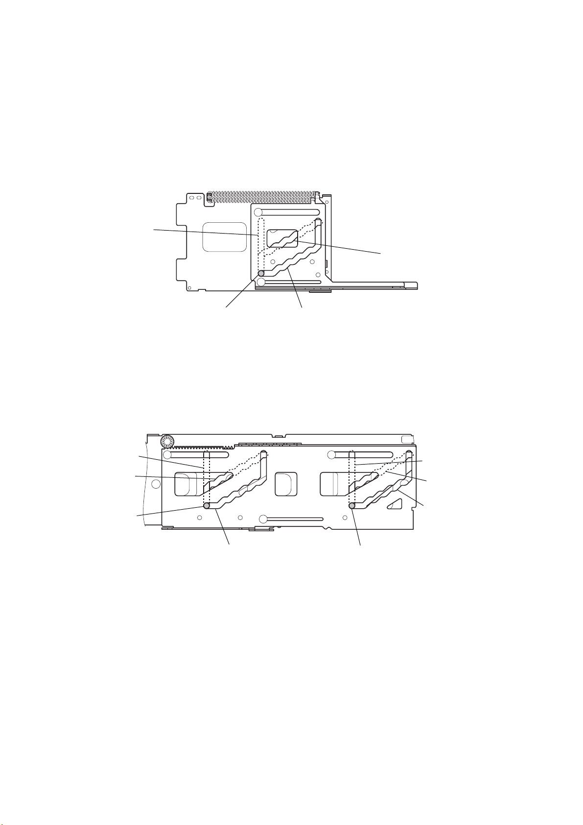
y
SECTION 4
ASSEMBLY
4-1. ADJUSTING PHASE OF A SLIDE PLATE, B SLIDE PLATE,
C SLIDE PLATE AND D SLIDE PLATE.
•When installing the elevator section, slide A slide plate and B slide plate, C slide plate and D slide plate respectively, install the axis of
the elevator chassis assy as shown in the figure.
• Align holes of A slide plate and B slide plate
with the hole of the front plate assy as shown in the figure.
hole of front plate assy
hole of B slide plate
hole of base chassis assy
hole of C slide plate
axis of elevator chassis assy
axis of elevator chassis assy
hole of D slide plate
hole of A slide plate
• Align holes of C slide plate and D slide plate
with the hole of the base chassis assy as
shown in the figure.
hole of base chassis ass
hole of C slide plate
hole of D slide plate
axis of elevator chassis assy
20

SECTION 5
r
e
ELECTRICAL ADJUSTMENTS
DVX-100S
Preparation
• Use DVD-ROM disc for test as follows.
NTSC:
HLX-504 (J-6090-088-A) (single layer)
HLX-505 (J-6090-089-A) (dual layer)
PAL:
HLX-506 (J-6090-077-A) (single layer)
HLX-507 (J-6090-078-A) (dual layer)
• Before perform the adjustments, connect the FM modulator.
Video Frequency Adjustment
Connection:
frequency counte
MPEG board
TP (27MHz)
Procedure:
1. Connect a fr equency counter to TP (27MHz) and GND on the
MPEG board.
2. Adjust CT501 on the MPEG board so that the frequency
counter reads 27 MHz ± 0.1 kHz.
+
–
Video Output Level Adjustment
Connection:
oscilloscop
MPEG board
CS151
1
(VIDEO OUT REAR)
CS151 3 (GND)
Procedure:
1. Connect an oscilloscope to CS151 pin 1 (VIDEO OUTPUT
REAR) and pin 3 (GND) on the MPEG board.
2. Playback the color bars (100%) of the test disc.
3. Adjust SVR181 on the MPEG board so that the wa veform le vel
of the oscilloscope is 1.0 ± 0.1 Vp-p.
+
–
1.0 ± 0.1 Vp-p
Adjustment Location:
– MPEG BOARD (Component Side) –
SVR181
Video Output Level
Adjustment
– MPEG BOARD (Conductor Side) –
CS151
6
CT501
Video Frequency
Adjustment
1
TP (27MHz )
21
 Loading...