

Sony DSLR-A580 Service manual
DSLR-A560/A560L/A560Y/A580/A580L/
SERVICE MANUAL
A580Y/A580J
LEVEL 2
983452131.pdf
Revision History
Ver. Date History Contents
1.0 2010.09 Official Release — —
S.M. Rev.
issued
Ver. 1.0 2010.09
Photo: DSLR-A580
SERVICE NOTE (Check the following note before the service.)
– ENGLISH –
1-1. METHOD OF REPLACING THE FOCUS PLATE
1-2. PRECAUTION ON REPLACING THE AM-025 BOARD
1-3. METHOD FOR CHECKING THE AS SLIDER UNIT (863)
1-4. METHOD FOR ADJUSTING THE TEBURE REVISE
1-5. METHOD FOR REPLACING THE AS SLIDER B ASSY
1-6. METHOD FOR REPLACING THE AS HOLDER ACTUATOR ASSY
US Model
AEP Model
UK Model
E Model
Australian Model
Chinese Model
Korea Model
[About the service of this model]
DSLR-A560L/A580L is a commodity that packed the Interchangeable Lens Digital Camera (DSLR-A560/A580) and Zoom Lens Kit (DT 18-55mm
F3.5-5.6 SAM).
DSLR-A560Y/A580Y is a commodity that packed the Interchangeable Lens Digital Camera (DSLR-A560/A580) and W Zoom Lens Kit (DT 18-55mm
F3.5-5.6 SAM/DT 55-200mm F4-5.6 SAM).
DSLR-A580J is a commodity that packed the Interchangeable Lens Digital Camera (DSLR-A580) and Zoom Lens Kit (DT 18-250mm F3.5-6.3).
Refer to each following service manual of the Zoom lens kit, when you repair.
• Zoom Lens Kit
SAL1855 (DT 3.5-5.6/18-55 SAM) (DT 18-55mm F3.5-5.6 SAM) Service Manual (9-852-691-1[])
SAL55200-2 (DT 4-5.6/55-200 SAM) (DT 55-200mm F4-5.6 SAM) Service Manual (9-852-692-1[])
SAL18250 (3.5-6.3/18-250) (DT 18-250mm F3.5-6.3) Service Manual (9-852-228-1[])
INTERCHANGEABLE LENS DIGITAL CAMERA/ZOOM LENS KIT
The components identified
by mark 0 or dotted line with
mark 0 are critical for safety.
Replace only with part number
specified.
DSLR-A560/A560L/A560Y/A580/A580L/A580Y/A580J_L2
9-834-521-31
Sony Corporation
2010I29-1
© 2010.09
Published by Sony Techno Create Corporation
Camera
[System]
Camera Type
Lens A-mount lens
[Image sensor]
Image format
Total pixel number of image sensor
Effective pixel number of camera
[SteadyShot]
System Image sensor-shift
Effect Approx. 2.5 EV to 4 EV in
[Anti-Dust]
System Charge protection coating
[Auto focus system]
System TTL phase-detection
Metering points
Sensitivity Range
AF illuminator
[Live View]
Type Pentamirror tilt mechanism
Image format
Frame coverage
Interchangeable Lens
Digital Camera
DSLR-A580
23.5mm×15.6mm (APSC format) “Exmor” CMOS
image sensor
DSLR-A560
23.4 mm×15.6 mm (APSC format) “Exmor” CMOS
image sensor
DSLR-A580
Approx. 16 700 000 pixels
DSLR-A560
Approx. 14 600 000 pixels
DSLR-A580
Approx. 16 200 000 pixels
DSLR-A560
Approx. 14 200 000 pixels
mechanism
shutter speed (depending
on shooting conditions and
th
e attached lens)
on Low-Pass Filter and
image sensor-shift
mechanism
system (Contrast AF
method is selectable in
focus check Live View
mode)
15 points (3 points cross
type) (11 points in
viewfinder mode)
–1 EV to 18 EV (at ISO
100 equivalent)
Approx. 1 m to 5 m
(3.3 feet to 16.4 feet)
Exclusive image sensor for
Live View
Approx. 90%
SPECIFICATIONS
[Viewfinder]
Type Fixed eye-level penta-
Frame coverage
Magnification
Eye Point Approximately 19 mm
Dioptor Adjustment
[Focus check Live View]
Image format
Frame coverage
[LCD monitor]
LCD panel 7.5 cm (3.0 type) TFT
Total number of dots
[Exposure control]
Metering Cell
Metering method
Metering Range
ISO sensitivity (Recommended
Exposure compensation
Dach-mirror
Approx. 95%
0.80 × with 50 mm lens at
infinity, –1 m
from the eyepiece, 15 mm
from the eyepiece frame at
–1 m
–2.5 m
Image sensor for shooting
Approx. 100%
drive
921 600 (640 × 3 (RGB) ×
480) dots
Live View
Exclusive image sensor for
Live View
Viewfinder
40-segment honeycombpattern SPC
Focus check Live View
“Exmor” CMOS sensor
Live View/Focus check
Live View
1200-zone evaluative
metering
Viewfinder
TTL shutter-open metering
Live View
1 EV to 17 EV on all
metering modes, at ISO
100 equivalent with F1.4
lens)
Viewfinder
2 EV to 20 EV (4 EV to
20 EV on spot metering
mode) (ISO 100 equivalent
with F1.4 lens)
Focus check Live View
DSLR-A580
–2 EV
metering modes (ISO 100
equivalent with F1.4 lens
DSLR-A560
–2 EV to 16 EV on all
metering modes (ISO 100
equivalent with F1.4 lens)
exposure index)
AUTO, ISO 100 to 12800
±2.0 EV (1/3 EV step)
–1
–1
–1
to +1.0 m
to 17 EV on all
(diopter)
–1
[Shutter]
Type Electronically-controlled
Speed range 1/4000 second to 30
Flash sync speed
vertical-traverse, focalplane type
seconds, bulb, (1/3 EV
step)
1/160 second
[Built-In-Flash]
Flash guide number
Recycling time
Flash coverage
Flash compensation
GN 12 (in meters at ISO
100)
Approx. 4 seconds
Covering 18 mm lens
(focal length that the lens
indicates)
±2.0 EV (1/3 EV step)
[Recording format]
File format JPEG (DCF Ver. 2.0, Exif
Movie (AVCHD format)
Movie (MP4 format)
Ver. 2.3, MPF Baseline)
compliant, DPOF
compatible
AVCHD Ver. 1.0
compliant
Video: MPEG-4 AVC/
H.264
Audio: Dolby Digital 2ch,
equipped with Dolby
Digital Stereo Creator
• Manufactured under
rom Dolby
license f
Laboratories.
Video: MPEG-4 AVC/
H.264
Audio: MPEG-4 AAC-LC
2ch
[Recording media]
“Memory Stick PRO Duo”
media, SD card
[Input/output terminals]
USB miniB
HDMI HDMI type C minijack
MIC Terminal
REMOTE Terminal
Ø 3.5 mm Stereo minijack
[Power, general]
Used battery pack
Rechargeable battery pack
NP-FM500H
[Others]
Exif Print Compatible
PRINT Image Matching III
Compatible
Dimensions Approx. 137 mm ×
Mass Approx. 679 g (1 lb 7.9 oz)
Operating temperature
USB communication
104 mm × 84 mm
(5 1/2 inches × 4 1/8 inches
× 3 3/8 inches) (W/H/D,
excluding protrusions)
(with battery and “Memory
Stick PRO Duo” media)
Approx. 599 g (1 lb 5.1 oz)
(body only)
0°C to 40°C (32°F to
104°F)
Hi-Speed USB (USB 2.0
compliant)
BC-VM10 Battery charger
Input rating 100 V - 240 V AC, 50/60
Output rating
Operating temperature range
Storage temperature range
Maximum dimensions
Mass Approx. 90 g (3.2 oz)
Hz, 9 W
8.4 V DC, 0.75 A
0°C to 40°C (32°F to
104°F)
–20°C to +60°C (–4°F to
+140°F)
Approx. 70mm × 25 mm ×
95 mm (2 7/8 inches ×
1 inches × 3 3/4 inches)
(W/H/D)
Rechargeable battery pack
NP-FM500H
Used battery
Maximum voltage
Nominal voltage
Maximum charge voltage
Maximum charge current
Capacity
Typical 1
Minimum 11.5
Maximum dimensions
Mass Approx. 78 g (2.8 oz)
Design and specifications are subject
to change without notice.
Lithium-ion battery
DC 8.4 V
DC 7.2 V
DC 8.4 V
2.0 A
1.8 Wh (1 650 mAh)
Wh (1 600 mAh)
Approx. 38.2 mm ×
20.5 mm × 55.6 mm
(1 9/16 inches × 13/16
inches × 2 1/4 inches)
(W/H/D)
Model information table
Model DSLR-A560 DSLR-A560L DSLR-A560Y
Destination US, AEP, UK, E US, AEP, UK, E, CH AEP, UK, E
Imager sensor 14M 14M 14M
Lens
×
DT 18-55mm F3.5-5.6 SAM
Model DSLR-A580 DSLR-A580L DSLR-A580Y DSLR-A580J
Destination
US, AEP, UK, E, AUS, CH,
KR
US, AEP, UK, E, CH, KR AEP, UK, E, AUS, KR CH
Imager sensor 16M 16M 16M 16M
Lens
• Abbreviation
AUS : Australian model
CH : Chinese model
KR : Korea model
×
DT 18-55mm F3.5-5.6 SAM
DT 18-55mm F3.5-5.6 SAM/
DT 55-200mm F4-5.6 SAM
DT 18-55mm F3.5-5.6 SAM/
DT 55-200mm F4-5.6 SAM
DT 18-250mm F3.5-6.3
DSLR-A560/A560L/A560Y/A580/A580L/A580Y/A580J_L2
– 2 –

CHEMICALS
Some chemicals used for servicing are highly volatile.
Their evaporation caused by improper management affects your health
and environment, and wastes resources.
Manage the chemicals carefully as follows.
• Store chemicals sealed in a specific place to prevent from exposure
to high temperature or direct sunlight.
• Avoid dividing chemicals into excessive numbers of small containers
to reduce natural evaporation.
• Keep containers sealed to avoid natural evaporation when chemicals
are not in use.
• Avoid using chemicals as much as possible. When using chemicals,
divide only required amount to a small plate from the container and
use up it.
PLASTIC PARTS
Be careful to the following points for plastic parts used in this unit.
• Use a piece of cleaning paper or cleaning cloth for cleaning plastic
parts. Avoid using chemicals.
Even if you have to use chemicals to clean heavy dirt, don’t use paint
thinner, ketone, nor alcohol.
• Insert the specific screws vertically to the part when installing a
plastic part.
Be careful not to tighten screws too much.
Danger of explosion if battery is incorrectly replaced.
Caution
Replace only with the same or equivalent type.
Dispose of used batteries according to the instructions.
SAFETY-RELATED COMPONENT WARNING!!
COMPONENTS IDENTIFIED BY MARK 0 OR DOTTED LINE WITH
MARK 0 ON THE SCHEMATIC DIAGRAMS AND IN THE PARTS LIST
ARE CRITICAL TO SAFE OPERATION. REPLACE THESE COMPONENTS WITH SONY PARTS WHOSE PART NUMBERS APPEAR AS
SHOWN IN THIS MANUAL OR IN SUPPLEMENTS PUBLISHED BY
SONY.
SAFETY CHECK-OUT
After correcting the original service problem, perform the following
safety checks before releasing the set to the customer.
1. Check the area of your repair for unsoldered or poorly-soldered
connections. Check the entire board surface for solder splashes and
bridges.
2. Check the interboard wiring to ensure that no wires are “pinched”
or contact high-wattage resistors.
3. Look for unauthorized replacement parts, particularly transistors,
that were installed during a previous repair. Point them out to the
customer and recommend their replacement.
4. Look for parts which, through functioning, show obvious signs of
deterioration. Point them out to the customer and recommend their
replacement.
5. Check the B+ voltage to see it is at the values specified.
6. Flexible Circuit Board Repairing
• Keep the temperature of the soldering iron around 270 °C during
repairing.
• Do not touch the soldering iron on the same conductor of the circuit
board (within 3 times).
• Be careful not to apply force on the conductor when soldering or
unsoldering.
UNLEADED SOLDER
This unit uses unleaded solder.
Boards requiring use of unleaded solder are printed with the lead free
mark (LF) indicating the solder contains no lead.
(Caution: Some printed circuit boards may not come printed with the
lead free mark due to their particular size.)
: LEAD FREE MARK
Be careful to the following points to solder or unsolder.
• Set the soldering iron tip temperature to 350 °C approximately.
If cannot control temperature, solder/unsolder at high temperature
for a short time.
Caution: The printed pattern (copper foil) may peel away if the
heated tip is applied for too long, so be careful!
Unleaded solder is more viscous (sticky, less prone to
flow) than ordinary solder so use caution not to let solder
bridges occur such as on IC pins, etc.
• Be sure to control soldering iron tips used for unleaded solder and
those for leaded solder so they are managed separately. Mixing unleaded solder and leaded solder will cause detachment phenomenon.
DSLR-A560/A560L/A560Y/A580/A580L/A580Y/A580J_L2
– 3 –
1. SERVICE NOTE
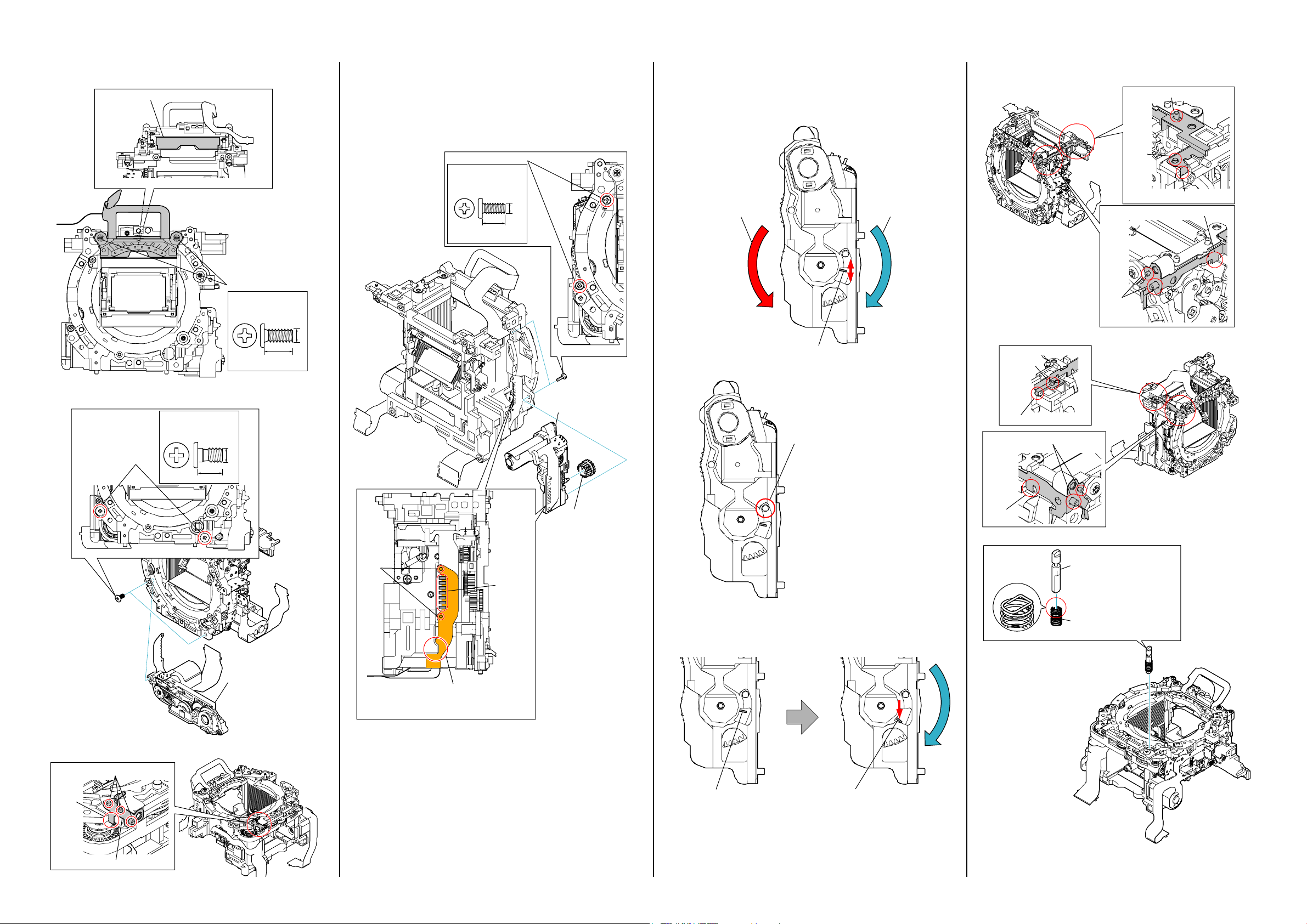
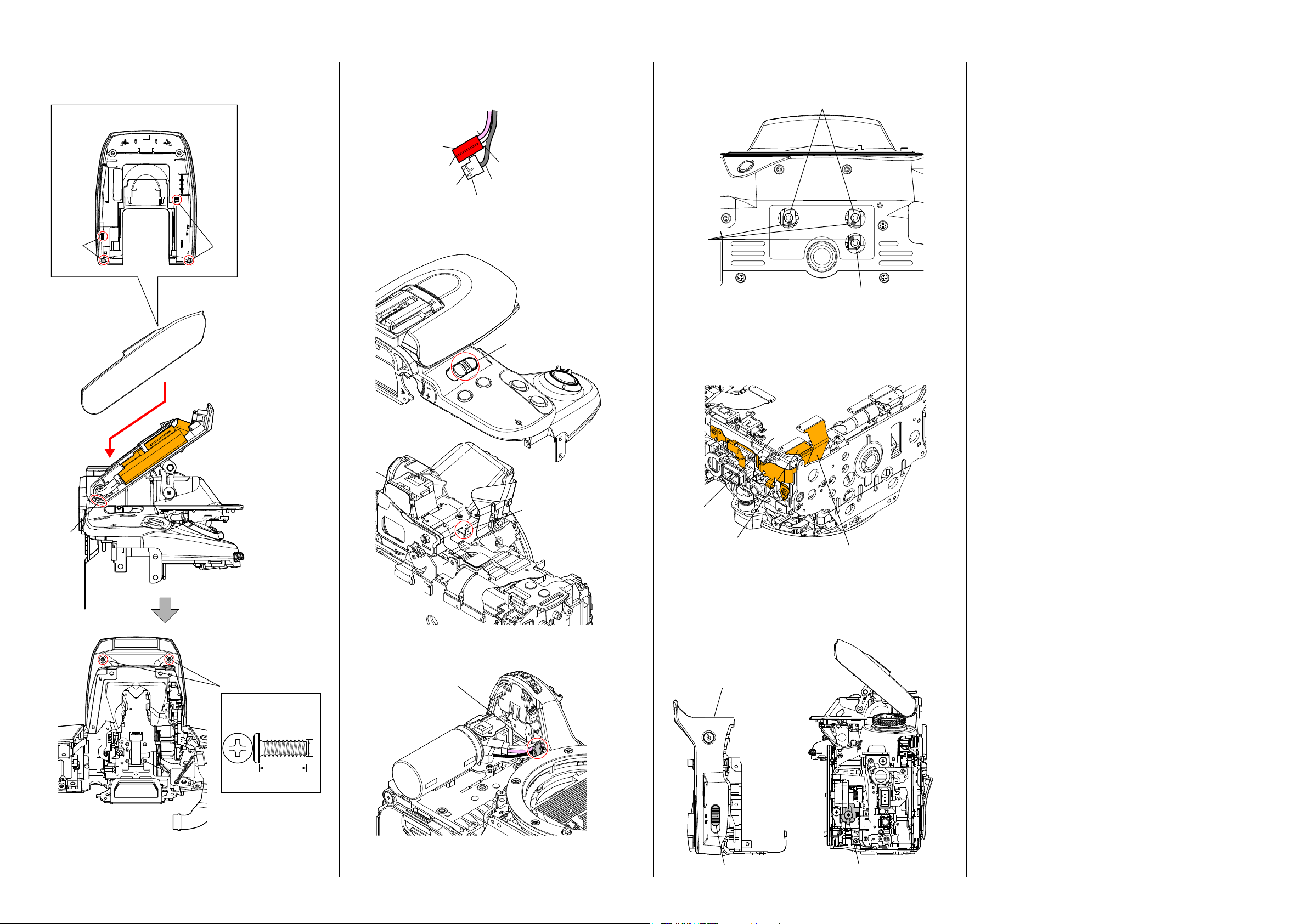
1-1. METHOD OF REPLACING THE FOCUS PLATE 1-3. METHOD FOR CHECKING THE AS SLIDER UNIT (863)
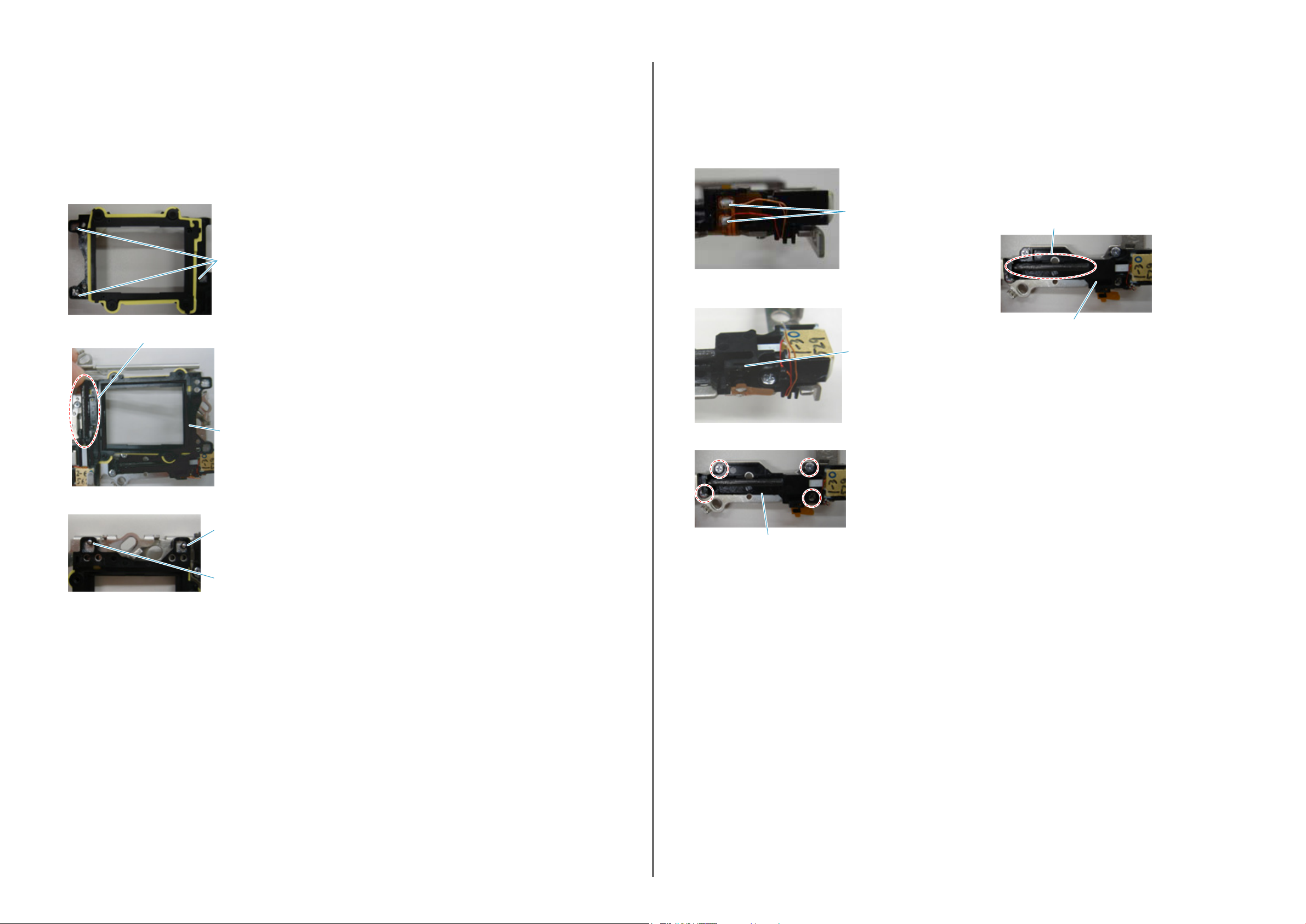
1 Remove two claws pushing part A below,
and remove the VM FS Retainer in the direction
of arrow.
Claw
A
Claw
VM FS Retainer
2 Remove the VM FS Retainer.
VM FS Retainer
3 Remove the Focus Plate and the VB Spacer.
VB Spacer
Focus Plate
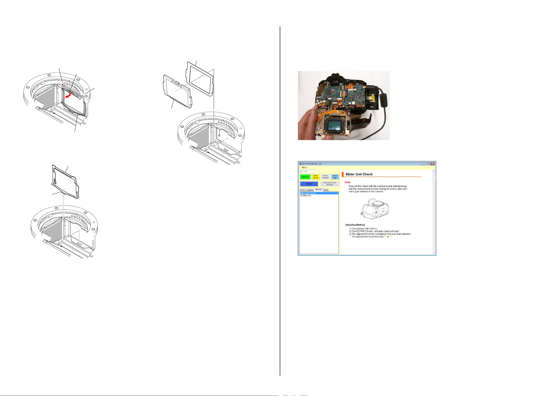
Make sure to confirm below before replacing the AS Slider B Assy or the AS Holder Actuator Assy.
(1) Remove the CV Rear Cover Assy (865), and temporally mount the AS Slider Unit (863).
(2) Set the AS Slider Unit (863) upwards as shown in figure, and put it on a stable place.
(3) Select “Slider Unit Check” of the adjustment software, and then confirm the movement to the directions of Pitch and Yaw, and if an error occurs,
replace it with the component part corresponding to the movement.
Claw
1-2. PRECAUTION ON REPLACING THE AM-025 BOARD
Destination Data
When you replace to the repairing board, the written destination data of repairing board also might be changed to original setting.
USB Serial No.
The set is shipped with a unique ID (USB Serial No.) written in it.
This ID has not been written in a new board for service, and therefore it must be entered after the board replacement.
DSLR-A560/A560L/A560Y/A580/A580L/A580Y/A580J_L2
1-1
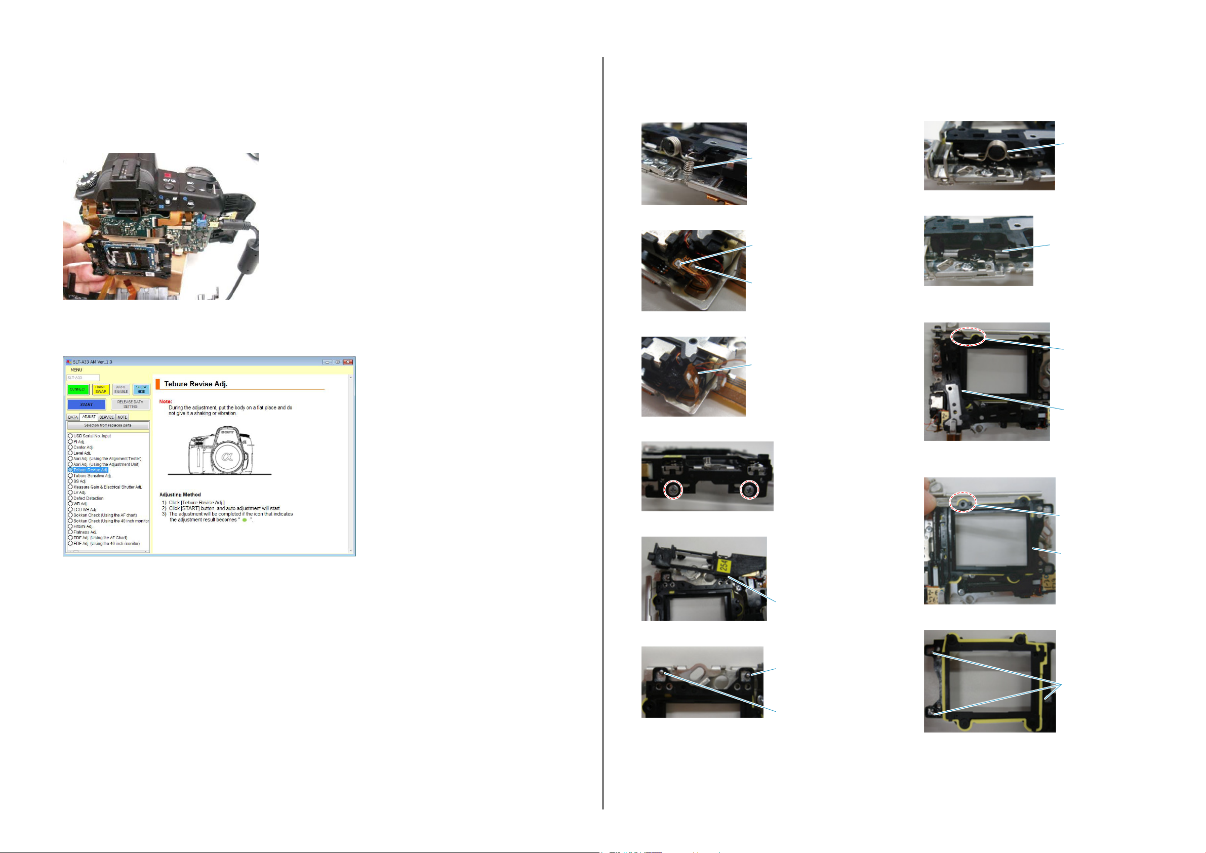
1-4. METHOD FOR ADJUSTING THE TEBURE REVISE
y
1-5. METHOD FOR REPLACING THE AS SLIDER B ASSY
Make sure to confirm below after replacing the AS Slider B Assy or the AS Holder Actuator Assy.
(1) Remove the CV Rear Cover Assy (865), temporally mount the AS Slider Unit (863) mounted with the Imager Sensor, and then set up the camera
body and hold the AS Slider Unit (863) as shown in figure.
(2) Select “Slider Unit Check” of the adjustment software, and then confirm if the result is OK.
(3) Select “Tebure Revise Adj.” of the adjustment software, and then confirm if the result is OK.
(4) Mount the AS Slider Unit (863) to the camera.
Removal Procedure
(1) Remove the spring.
Spring
(2) Remove the solder on the enamel wires at two places.
Solder
Solder
(3) Remove the flexible board from the AS Slider B Assy.
Flexible Board
(7) Remove two Cap SPs (for Pitch and Yaw).
Cap SP
(8) Remove two Caps (for Pitch and Yaw).
Cap
(9) Remove the AS Slider A Assy.
It can be done easily if A is removed beforehand.
A
(4) Remove two screws.
(10) Remove the AS Slider B Assy.
It can be done easily if B is removed beforehand.
AS Slider A Assy
B
(5) Remove the AS Unit Holder Ball.
AS Unit Holder Ball
(6) Remove two Ball Bearings.
(11) Remove three Ball Bearings.
AS Slider B Ass
Ball Bearing
Ball Bearing
DSLR-A560/A560L/A560Y/A580/A580L/A580Y/A580J_L2
1-2
Ball Bearing
1-6. METHOD FOR REPLACING THE AS HOLDER ACTUATOR ASSY
G-15 andGG-116
Assembly Procedure
Note: Make sure to perform the assembly procedures after assembling the AS Holder Actuator Assy.
The assembly procedure is the reverse of the removal procedure.
Apply grease to the portions indicated below.
* Refer to “SUBSIDIARY MATERIALS” on page 2-2 for the part number of grease.
* After applying grease, attach the Ball Bearings.
Ball Bearing
G G-15
G G-15 and G G-116
AS Slider B Assy
Removal Procedure
Note: Make sure to perform the removal procedures after removing the
AS Slider B Assy.
(1) Remove the solder on the enamel wires at two places.
Solder
(2) Remove the flexible board from the hook on the AS Holder Actuator
Assy.
Hook
(3) Remove four screws to remove the AS Holder Actuator Assy.
Assembly Procedure
Note: Make sure to perform the assembly procedures before assembling
the AS Slider B Assy.
The assembly procedure is the reverse of the removal procedure.
Apply grease to the portions indicated below.
* Refer to “SUBSIDIARY MATERIALS” on page 2-2 for the part
number of grease.
G
AS Holder Actuator Assy
* After applying grease, attach the Ball Bearings.
Ball Bearing
G G-15
Ball Bearing
G G-15
AS Holder Actuator Assy
DSLR-A560/A560L/A560Y/A580/A580L/A580Y/A580J_L2
1-3E
2. REPAIR PARTS LIST
IDENTIFYING PARTS
Follow the disassembly in the given numerical order.
7�Top Cover Section
[Disassembly]
[Exploded View]
qh�Mirror Box Section (Penta Unit)
[Disassembly]
[Exploded View]
qf�Battery Holder Section
[Disassembly]
[Exploded View]
• ST-218 Board
• GYJ-003 Flexible Board
• STG-001 Flexible Board
6�
BD Eye Piece Assy
• EYE-010 Flexible Board
qa�Anti Shake Unit Section
[Disassembly]
[Exploded View]
• Imager Section
• IM Imager Unit
• ISL-001 Flexible Board
• ISP-001 Flexible Board
• Anti Shake Unit Section
2�
Rear Cover Section
[Disassembly]
[Exploded View]
•
Rear Cover Section
•
LCD Section
• PD-390 Board
• LCD-014 Flexible Board
• SHD-001 Flexible Board
8�AM-025 Board
• MM-084 Board
(ENGLISH)
NOTE:
• -XX,-Xmeanstandardizedparts,sotheymayhavesomedifferencesfromtheoriginalone.
• Itemsmarked“*”arenotstockedsincetheyareseldomrequiredforroutineservice.Somedelay
shouldbeanticipatedwhenorderingtheseitems.
• Themechanicalpartswithnoreferencenumberintheexplodedviewsarenotsupplied.
• Duetostandardization,replacementsinthepartslistmaybedifferentfromthepartsspecified
inthediagramsorthecomponentsusedontheset.
• Abbreviation
AUS : Australian model
CH : Chinese model
KR : Korea model
View Position
Left View
Front View
Whenindicatingpartsbyreferencenumber,
pleaseincludetheboardname.
The components identified by mark 0 or
dottedlinewithmark0arecriticalforsafety.
Replaceonlywithpartnumberspecified.
• Color Indication of Appearance Parts
Example:
(SILVER) : Cabinet’s Color
(Silver) : Parts Color
Top View
Back View
Right View
Bottom View
3�
CV Grip Cover Assy
4�
CV Front Cover Assy (865)
qj�Mirror Box Section
[Disassembly]
[Exploded View]
• Sub Unit-1
• Sub Unit-2
qg�
ALX-8650 (AF Module)
0�
BD Bottom Frame
qs�Shutter Unit (AFE-3032)
qd�BD RT Ho
• SMR-001 Flexible
9�BD Main Frame
lder Assy
1�
Board
CV Side Cover L Assy
Link
DSLR-A560/A560L/A560Y/A580/A580L/A580Y/A580J_L2
ACCESSORIES
ACCESSORIES ASSEMBLYDISCHARGING OF THE CHARGING CAPACITOR
2-1
NOTE FOR REPAIR
• Makesurethattheflatcableandflexibleboardarenotcrackedor
bentattheterminal.
Donotinsertthecableinsufficientlynorcrookedly.
• When remove a connector,donotpullatwire of connector.It is
possiblethatawireissnapped.
• Wheninstallingaconnector,donotpressdownatwireofconnector.
Itispossiblethatawireissnapped.
• Donotapplyexcessiveloadtothegildedflexibleboard.
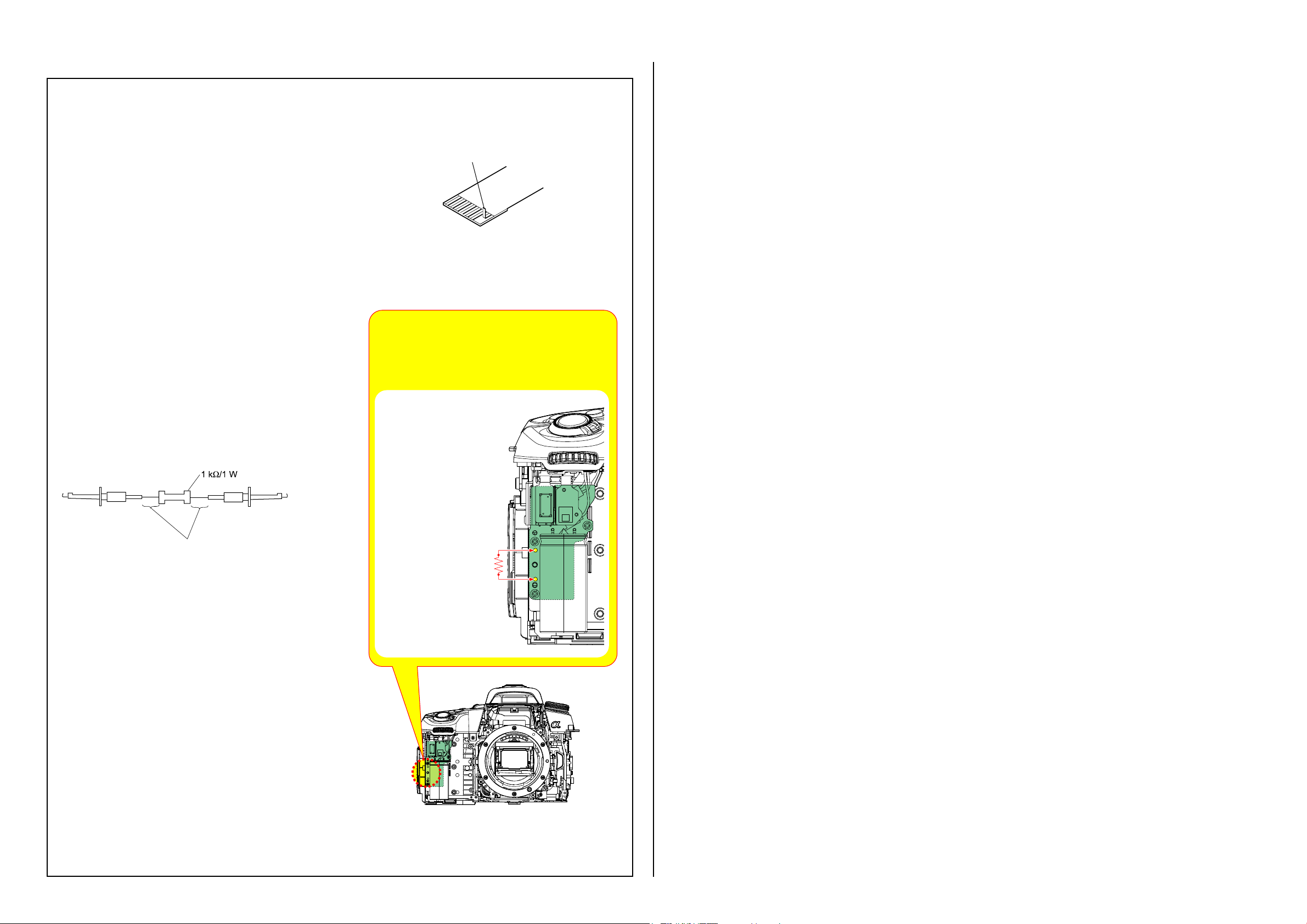
DISCHARGING OF THE CHARGING CAPACITOR
The charging capacitor is charged up to the maximum 330 V
potential.
There is a danger of electric shock by this high voltage when the
capacitor is handled by hand. The electric shock is caused by the
charged voltage which is kept without discharging when the main
power of the unit is simply turned off. Therefore, the remaining
voltage must be discharged as described below.
Preparing the Short Jig
To preparing the short jig, a small clip is attached to each end of
a resistor of 1 kΩ /1 W (1-215-869-11).
Wrap insulating tape fully around the leads of the resistor to
prevent electrical shock.
Cut and remove the part of gilt
which comes off at the point.
(Be careful that some
pieces of gilt may be left inside)
Note:Note: High-voltage cautionsHigh-voltage cautions
Discharging the Capacitor
Short-circuit between the two points with the short jig about
Short-circuit between the two points with the short jig about
10 seconds.
10 seconds.
To avoid the spark with the metal plate,wrap the short jig
To avoid the spark with the metal plate,wrap the short jig
with the insulation tape.
with the insulation tape.
Wrap insulating tape.
SUBSIDIARY MATERIALS
B: Adhesive bond
B-50 (J-6082-615-A)
G: Grease
G-15 (J-6082-619-A)
G-85 (J-6082-626-A)
G-116 (J-6082-628-A)
R:1 kΩ/1 W
(Part code: 1-215-869-11)
DSLR-A560/A560L/A560Y/A580/A580L/A580Y/A580J_L2
2-2
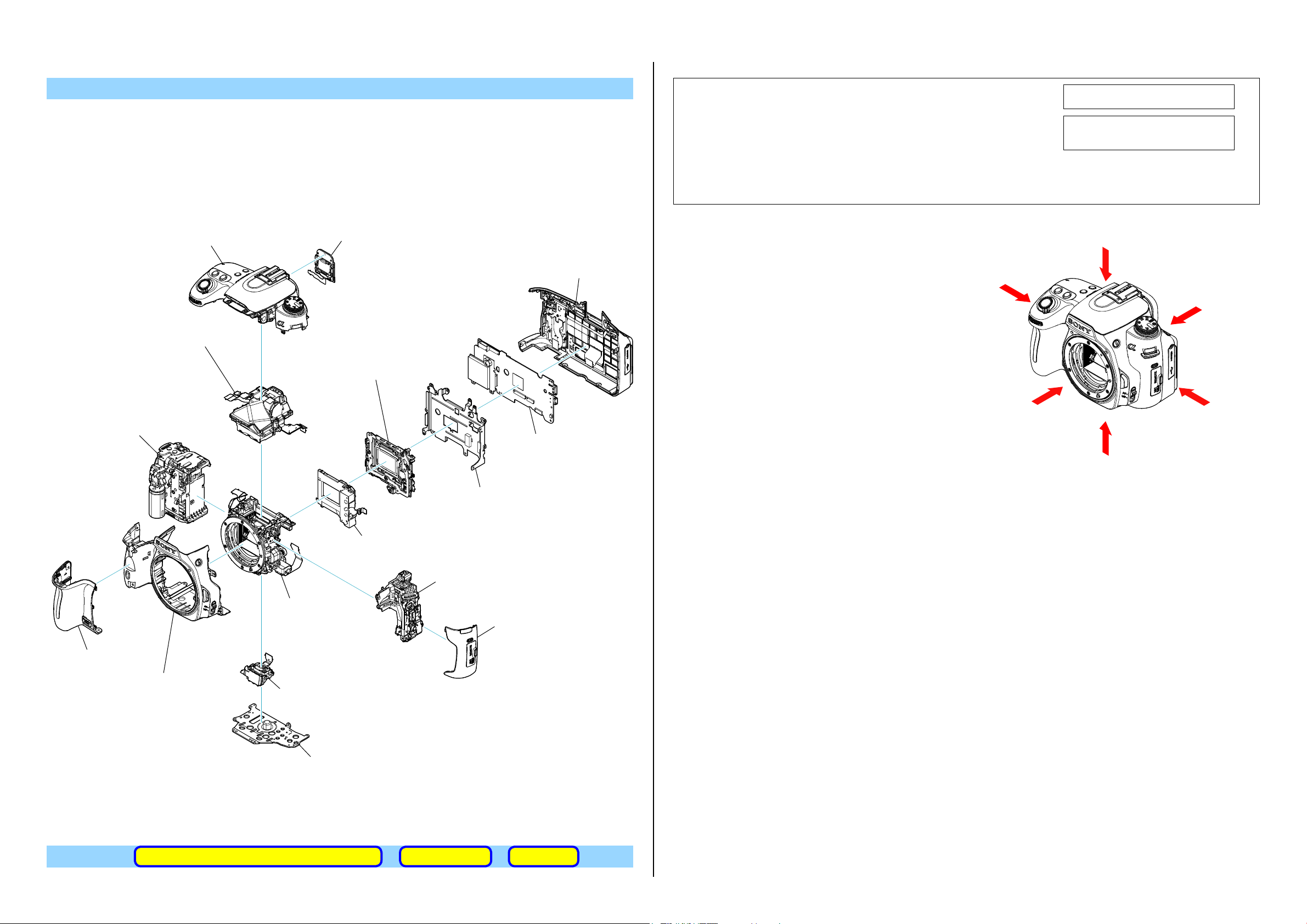
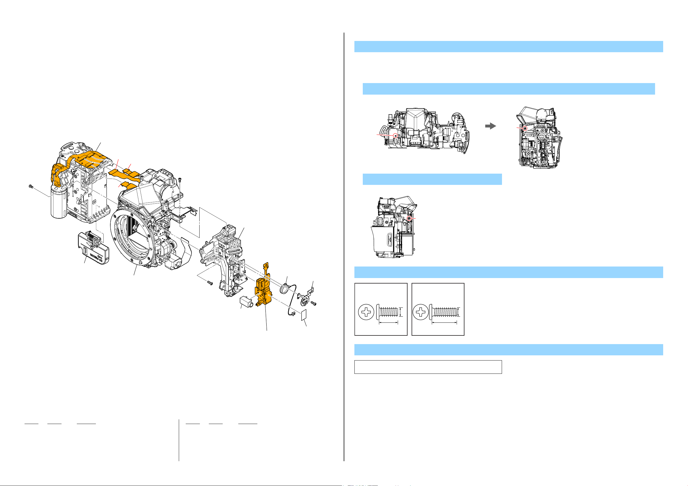
2-1. EXPLODED VIEWS
DISASSEMBLY
2-1-1. OVERALL SECTION
ns:notsupplied
Front Cover Section
(See Page 2-6)
1 1
1(Claw)
2 1
3
2-1
2-4
u-2
4
2-3
#12
1. Remove to numerical order (1 to 2) in the left figure.
2. The meaning of the sign in left figure is as follows. Be careful when it removes.
u-X: Flexible Board, Flat Cable, Harness
1 #2 X 1 → CV Remote Lid open (1) → #12 X 2
Bottom View
#2
Right View
#12
2 CV Eye Hood Assy (857) (2-1) → #112 X 1 → CV Diopter Adjust Dial (857) (2-2) →
#2 X 6 → #12 X 2 → CV DC Jack Lid open (2-3) → #12 X 1 → CV Media Lid open (2-4) →
Jack X 2 (2-5)
Back View Bottom View Right View Left View
#112
#12
ns
#2
2-5
AM-025
#12
u-2
#2
#2
2�Rear Cover Section
(See page 2-4)
2-2
#112
5
#2#2
#12 #12
Screw
#2: M1.7 X 4.0
(Black)
2-635-562-31
4.0
#12: M1.7 X 5.0 (Tapping)
(Black)
3-080-204-21
1.7
5.0
1.7
#112: M1.4 X 5.0
(Black)
2-178-410-11
1.4
5.0
Ref. No. Part No. Description Ref. No. Part No. Description
1 X-2549-446-1 CV SIDE COVER L ASSY
2 4-256-523-01 CV REMOTE LID
3 X-2514-442-1 CV EYE HOOD ASSY (857)
4 4-154-697-01 CV DC JACK LID
* 5 4-154-680-01 CV DIOPTER ADJUST DIAL (857)
#2 2-635-562-31 SCREW (M1.7)
#12 3-080-204-21 SCREW, TAPPING, P2
#112 2-178-410-11 TITE (UB TITE) 1.4
DSLR-A560/A560L/A560Y/A580/A580L/A580Y/A580J_L2
2-3
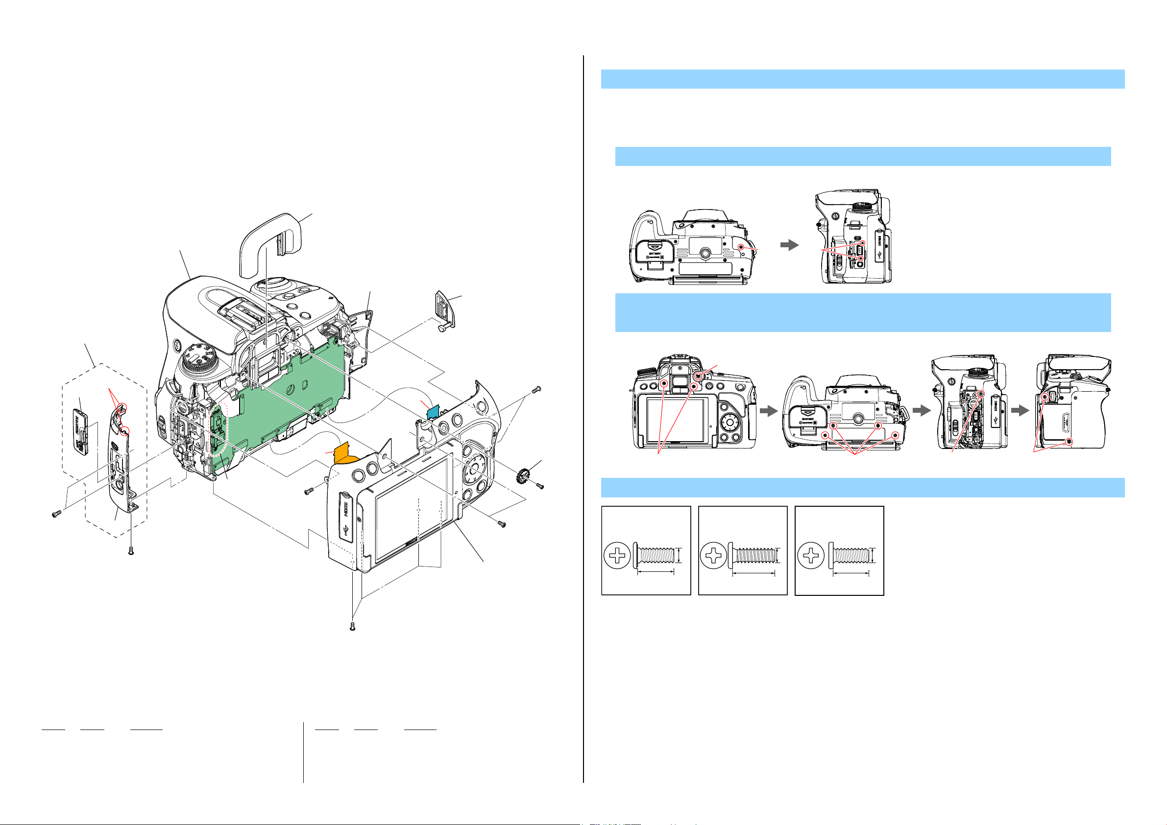
2-1-2. REAR COVER SECTION
ns:notsupplied
Screw
#8: M1.7 X 3.5 (Tapping)
(Silver)
3-078-890-01
#109: M1.7 X 3.0
(Black)
2-515-483-21
#140: M1.7 X 2.0
(Black)
2-635-562-01
#8
51
52
53
ns
54
55
57
58
56
#140
ns
60
Claw
59
65
LCD Section
(See page 2-5)
Claw
#109
61
#140
3.5
1.7
3.0
1.7
1.7
2.0
62
DSLR-A580/A580L/
A580Y/A580J
64
63
Ref. No. Part No. Description Ref. No. Part No. Description
51 1-489-274-11 SWITCH BLOCK, CONTROL (RS86500)
* 52 4-256-528-01 CV FUSE REPLACEMENT LABEL
53 X-2549-449-1 CV REAR COVER ASSY (865)
* 54 4-154-802-01 CV REAR RUBBER TAPE
* 55 4-154-801-01 CV REAR RUBBER
* 56 4-261-877-02 CV REAR CAUTION LABEL (865)
* 57 4-154-808-01 CV HINGE RIGHT COVER
58 X-2514-453-2 CV LCD FLEXIBLE COVER ASSY
* 59 4-154-817-01 CV FPC TAPE 857
60 4-154-720-01 BD CAPACITOR FIXED TAPE
* 61 4-154-809-01 CV HINGE LEFT COVER
* 62 4-258-191-01 EM REAR SHIELD SHEET
* 63 4-264-620-01 COVER, EM REAR SHIELD
* 64 4-156-877-01 CV FPC COVER SHEET
65 4-266-234-01 CV SILENCING CUSHION
#8 3-078-890-01 SCREW, TAPPING
#109 2-515-483-21 SCREW (M1.7), NEW TRU-STAR, P2
#140 2-635-562-01 SCREW (M1.7)
DSLR-A560/A560L/A560Y/A580/A580L/A580Y/A580J_L2
(DSLR-A580/A580L/A580Y/A580J)
2-4

2-1-3. LCD SECTION
112
113
Screw
#12: M1.7 X 5.0 (Tapping)
(Black)
3-080-204-21
5.0
1.7
#12
101
Claw
102
Claw
Claw
106
105
103
107
Claw
104
PD-390
108
111
LCD901
109
110
Ref. No. Part No. Description Ref. No. Part No. Description
101 X-2514-440-1 LCD HINGE ASSY
* 102 4-155-014-01 CV LCD LOWER COVER 858
103 1-880-443-11 LCD-014 FLEXIBLE BOARD
* 104 4-154-811-01 CV FPC INSULATING SHEET
105 A-1735-912-A SHD-001 FLEXIBLE BOARD, COMPLETE
* 106 4-154-817-01 CV FPC TAPE 857
* 107 4-154-816-01 CV SENSOR WINDOW
108 A-1792-091-A PD-390 BOARD, COMPLETE
109 4-154-810-01 CV RELAY PC BOARD FIXED TAPE
110 X-2514-459-1 CV UNIT CASE ASSY 858
111 4-155-013-01 CV LCD CUSHION 858
112 4-155-012-01 CV LCD WINDOW 858
* 113 4-155-015-01 CV LCD UPPER COVER 858
LCD901 8-753-324-36 ACX396BLN-1
#12 3-080-204-21 SCREW, TAPPING, P2
DSLR-A560/A560L/A560Y/A580/A580L/A580Y/A580J_L2
2-5

2-1-4. FRONT COVER SECTION
7�Top Cover Section
(See page 2-7)
(Note1, 2)
#2
#12
#12
#12
4-2
BB
6�153
u-6
C
#8
DISASSEMBLY
#2
1. Remove to numerical order (3 to 7) in the left figure.
2. The meaning of the sign in left figure is as follows. Be careful when it removes.
u-X: Flexible Board, Flat Cable, Harness
3 #12 X 2
Left View Bottom View
154
#12
#12
3�151
#12
3(Claw)
#12
3(Claw)
152
4-1
157
5
156
A
#8
u-4
155
u-7
Main Board Section
(See page 2-8)
#12
C
B
A
4 #12 X 1 → CV Eyelet Cover G (4-1) → #12 X 9 → #2 X 1 → POP up the Strobe (4-2) → #12 X 2
Left View Front View Bottom View Top View
#12
#12
#12
5
DISCHARGING OF THE CHARGING CAPACITOR
#12 #2
#12
6 #2 X 1
Back View
#2
#12
#12
#2
4�158
(Note3)
159
#12
Note
Note1: Refer to “Assembly-8: Top C ov er Bl oc kAssy” when y ou
assemble.
Note3: Refer to “Assembly-12:Assemble the CV FRONT COVER
ASSY”whenyouassemble.
Ref. No. Part No. Description Ref. No. Part No. Description
151 X-2549-447-1 CV GRIP COVER ASSY
* 152 4-154-696-21 CV EYELET COVER G
153 X-2514-445-1 BD EYE PIECE ASSY (857)
154 A-1735-726-A EYE-010 FLEXIBLE BOARD, COMPLETE
155 1-489-275-11 SWITCH BLOCK, CONTROL (PRV8650)
156 3-076-631-01 CV PRV FLEXIBLE FIXED TAPE
* 157 4-256-482-01 EM PREVIEW SHEET METAL
DSLR-A560/A560L/A560Y/A580/A580L/A580Y/A580J_L2
Note2: Referto “Assembly-9: Flash Unit (FL85700)Harness” when
youassemble.
158 X-2549-441-1 CV FRONT COVER ASSY (865) (Note3)
159 4-154-357-01 CV BOTTOM LABEL A (KR, CH)
159 4-256-505-01 CV BOTTOM LABEL B (EXCEPT KR, CH)
#2 2-635-562-31 SCREW (M1.7)
#8 3-078-890-01 SCREW, TAPPING
#12 3-080-204-21 SCREW, TAPPING, P2
2-6
7 #2 X 1 → #12 X 3
Left View Front View Back View
#2
Screw
#2: M1.7 X 4.0
(Black)
2-635-562-31
4.0
#8: M1.7 X 3.5 (Tapping)
(Silver)
3-078-890-01
1.7
#12
3.5
#12: M1.7 X 5.0 (Tapping)
(Black)
3-080-204-21
1.7
#12
1.7
5.0
2-1-5. TOP COVER SECTION
ns:notsupplied
201 (Note)
214
Screw
#8: M1.7 X 3.5 (Tapping)
(Silver)
3-078-890-01
#12: M1.7 X 5.0 (Tapping)
(Black)
3-080-204-21
#91: M1.7 X 3.0 (Tapping)
(Silver)
2-695-434-11
#172: M1.4 X 4.0 (Tapping)
(Black)
2-178-410-01
211
White
210
Pink
Black
#91
212
207
209
213
208
206
MIC901
205
#12
ns
203
204
215
216
CN901
217
#91
1.7
3.5
1.7
5.0
Note
Note: Referto“Assembly-7:TopCoverBlock”whenyouassemble.
3.5
1.7
1.4
4.0
#12
202
#12
#8
#8
Ref. No. Part No. Description Ref. No. Part No. Description
201 A-1792-106-A TOP COVER BLOCK ASSY (865)
(DSLR-A560/A560L/A560Y) (Note)
201 A-1792-107-A TOP COVER BLOCK ASSY (866)
(DSLR-A580/A580L/A580Y/A580J) (Note)
202 1-489-259-11 SWITCH BLOCK, CONTROL (TK86500)
203 4-256-481-01 BD EYE PIECE DUST CUSHION (865)
* 204 4-256-477-01 BD EYE PIECE FRAME
* 205 4-256-479-01 CV MICROPHONE HOLDER BASE
* 206 4-256-478-01 CV MICROPHONE HOLDER
207 X-2549-443-1 CV TOP COVER ASSY (865)
(DSLR-A560/A560L/A560Y)
207 X-2549-444-1 CV TOP COVER ASSY (866)
(DSLR-A580/A580L/A580Y/A580J)
208 4-190-771-01 CT POWER LEVER CLICK PLATE
209 X-2549-350-1 CT RELEASE BUTTON (M) ASSY
* 210 1-569-617-11 HOUSING, CONNECTOR 2P (White)
211 1-820-649-11 HOUSING, CONNECTOR 2P (Red)
* 212 X-2514-438-1 ST STROBE GUIDE ARM ASSY (R)
* 213 4-154-743-01 ST STROBE HINGE COLLAR
0 214 1-487-407-11 FLASH UNIT (FL85700)
215 4-256-480-01 ST STROBE COVER
216 X-2549-442-1 ST STROBE BASE COVER ASSY
* 217 X-2514-439-1 ST STROBE GUIDE ARM ASSY (L)
218 4-143-883-11 LOGO EMBLEM (A)
219 X-2514-448-2 ST STROBOSCOPE LOCK ASSY
CN901 1-822-402-11 SHOE CONNECTOR
MIC901 1-542-757-71 MICROPHONE UNIT
PL901 1-455-061-11 SOLENOID, PLUNGER
#8 3-078-890-01 SCREW, TAPPING
#12 3-080-204-21 SCREW, TAPPING, P2
#91 2-695-434-11 SCREW (T1.7), HEAD PAN TAPPING
#172 2-178-410-01 TITE (UB TITE) 1.4
#172
PL901
#8
DSLR-A560/A560L/A560Y/A580/A580L/A580Y/A580J_L2
218
219
#8
2-7
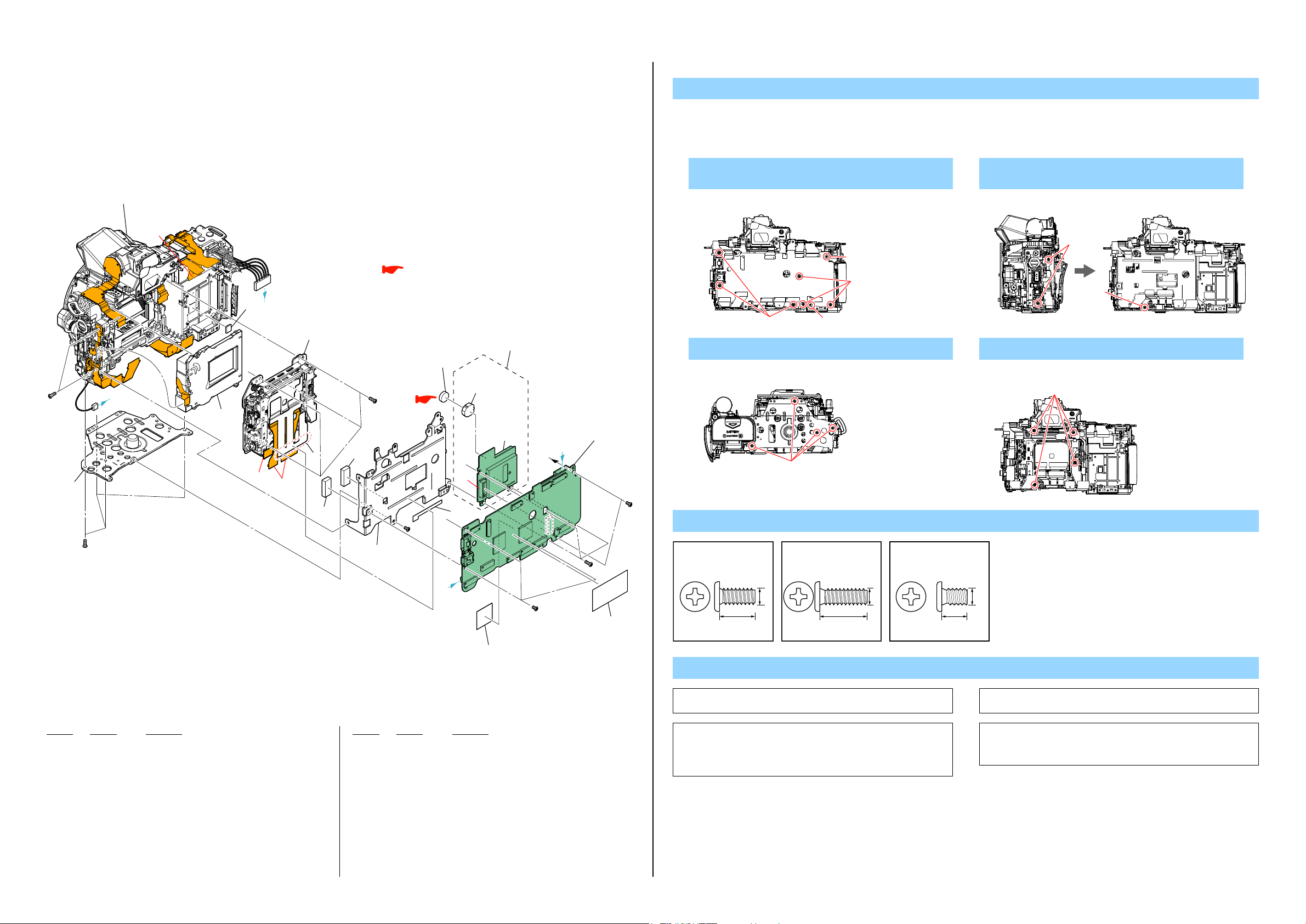
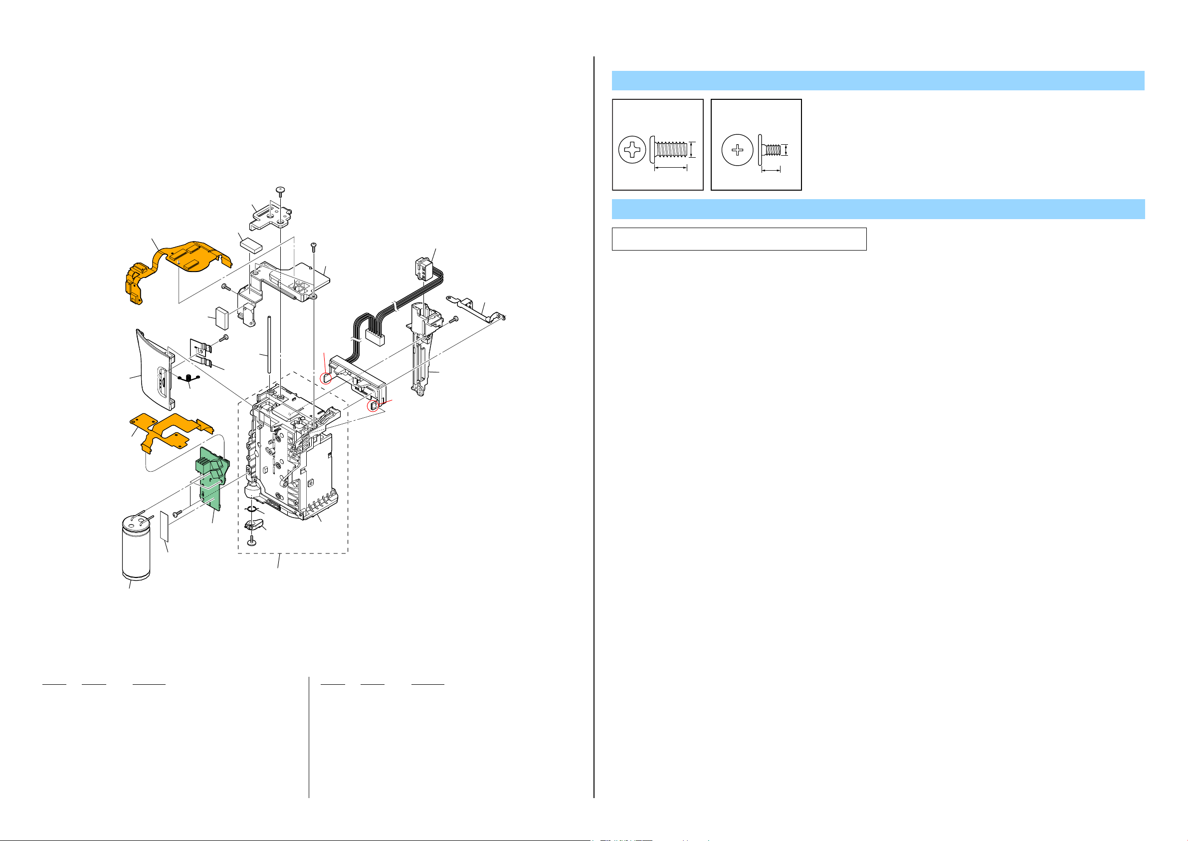
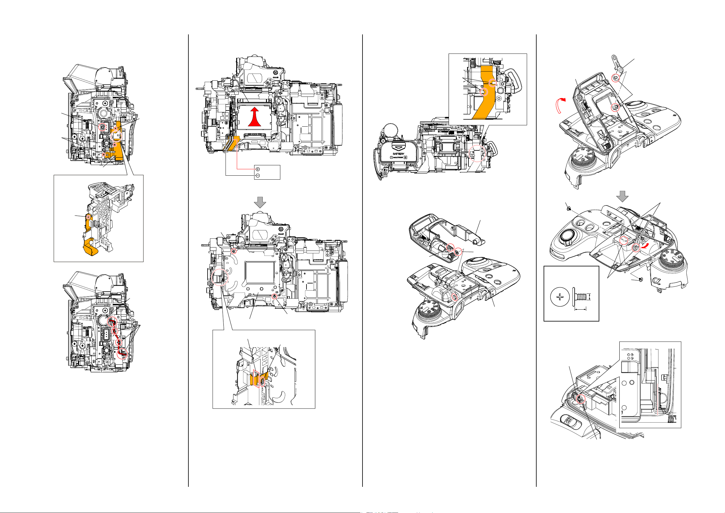
2-1-6. MAIN BOARD SECTION
ns:notsupplied
DISASSEMBLY
1. Remove to numerical order (8 to qs) in the left figure.
2. The meaning of the sign in left figure is as follows. Be careful when it removes.
u-X: Flexible Board, Flat Cable, Harness
#12
0 251
Remote Holder Section
(See Page 2-11)
u-8
A
#12
qs 253
(Note1)
C
252
B
qa�Imager Section
u-8
u-8
(See page 2-9)
9
254
#12
254
9 255
: BT900 (LITHIUM BATTERY)
Board on the mount position.
(See page Level3 6-50)
BT900
(CAUTION)
(Note3)
BH4501
(Note3)
257 8
ns
u-8
256
#109
B
C
AM-025
8�258
(Note2)
#12
#8
8 #8 X 2 → #109 X 3 → #12 X 3 →
MM-084 Board (8)
Back View
#8
#12
#109 #8
0 #12 X 4 qa #12 X 4
Bottom View
#12
Screw
#8: M1.7 X 3.5 (Tapping)
(Silver)
3-078-890-01
#12: M1.7 X 5.0 (Tapping)
(Black)
3-080-204-21
#109: M1.7 X 3.0
(Black)
2-515-483-21
9 #12 X 2 → #109 X 1 →
EM GF Tape (A) (9)
Right View
#12
#109
Back View
#12
Back View
A
Ref. No. Part No. Description Ref. No. Part No. Description
251 4-256-511-01 BD BOTTOM FRAME
* 252 4-159-021-01 EM MEDIA EMI SHEET
253 1-487-960-11 SHUTTER UNIT (AFE-3032) (Note1)
* 254 4-256-516-01 CUSHION, BD LIGHT INTERCEPTION
* 255 4-256-512-01 BD MAIN FRAME
256 4-192-226-01 EM GF TAPE (A)
257 A-1792-100-A MM-084 BOARD, COMPLETE
258 A-1797-666-A AM-025 BOARD, COMPLETE (SERVICE)
(DSLR-A560/A560L/A560Y) (Note2)
258 A-1797-667-A AM-025 BOARD, COMPLETE (SERVICE)
(DSLR-A580/A580L/A580Y/A580J) (Note2)
259 4-264-622-01 EM AM PCB SPACER
260 4-256-513-01 EM AM PCB SHIELD SHEET
0 BH4501 1-756-615-61 HOLDER, BATTERY (Note3)
0 BT900 1-756-135-31 BATTERY LITHIUM SECONDARY (CAUTION) (Note3)
#8 3-078-890-01 SCREW, TAPPING
#12 3-080-204-21 SCREW, TAPPING, P2
#109 2-515-483-21 SCREW (M1.7), NEW TRU-STAR, P2
DSLR-A560/A560L/A560Y/A580/A580L/A580Y/A580J_L2
260
#109
259
2-8
1.7
3.5
1.7
5.0
Note
Note1: Refer to “Assembly-5: Shutter Unit (AFE-3032)” when you
Note3: Replacethebatteryholder(BH4501)togetherwhenreplacing
(thebatteryholderremovedoncecannotbeusedagain.)
When mounting these parts, mount new battery holder first
assemble.
thelithiumbattery(BT900)ontheMM-084Board.
andattachnewlithiumbatterynext.
1.7
3.0
Note2: Referto “Assembly-11:Note on attachment of the SMR-001
andtheSLK-006FlexibleBoard”whenyouassemble.
Caution:
Dangerofexplosionoccursifbatteryisincorrectlyreplaced.Replaceonly
withthesameorequivalenttype. Disposeofusedbatteriesaccording
totheinstructions.

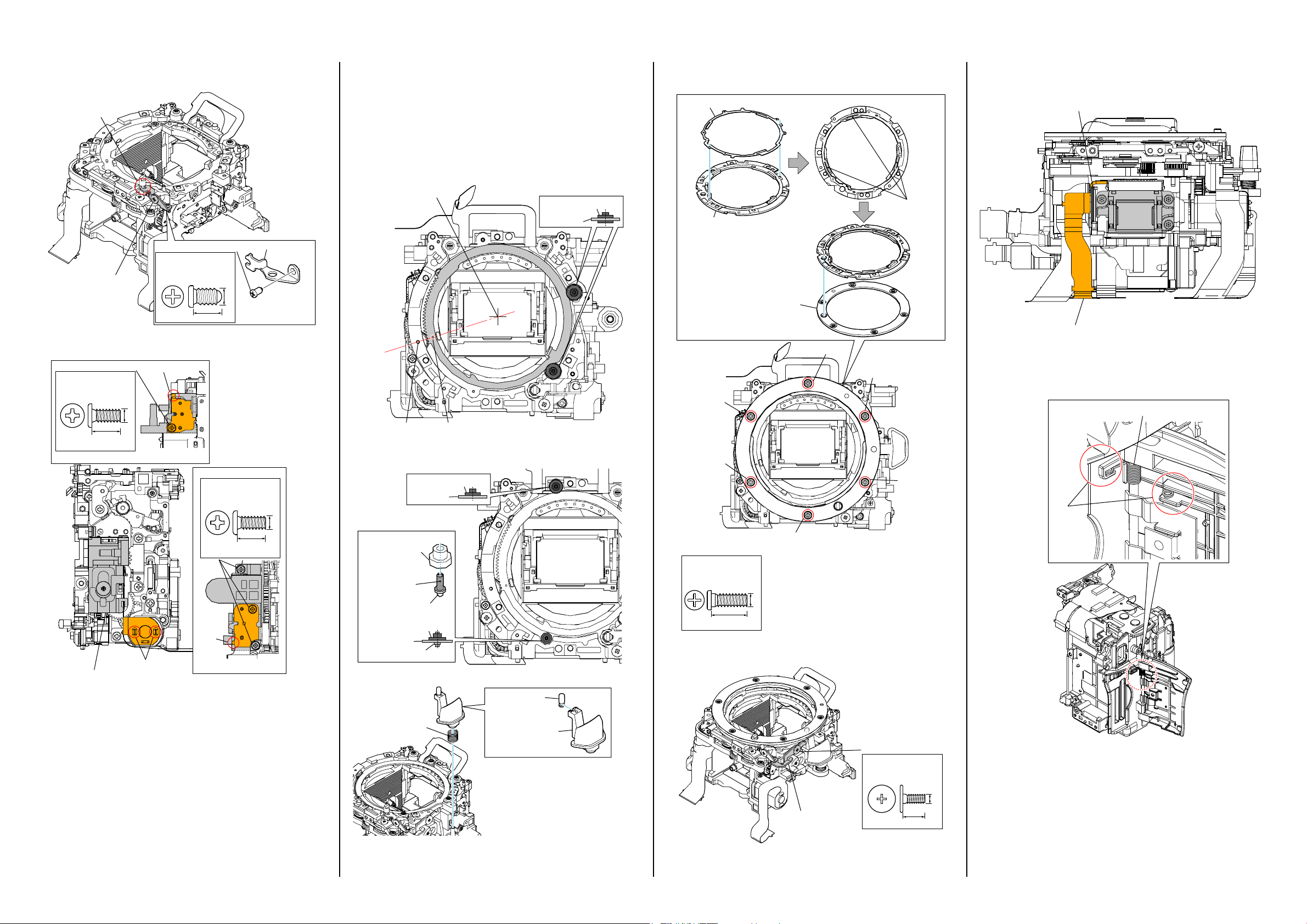
2-1-7. IMAGER SECTION
Peel off the
ns:notsupplied
Anti Shake Unit Section
(See page 2-10)
(including HOL-007 flexible board)
301 (including CP001 (DSLR-A560/A560L/A560Y) /
IC4501 (DSLR-A580/A580L/A580Y/A580J) (CMOS imager) and
IS-073 (DSLR-A580/A580L/A580Y/A580J) /
IS-077 (DSLR-A560/A560L/A560Y) complete board)
(Note1, 2, 3, 4)
Screw
#64: M1.7 X 5.0 (Tapping)
(Silver)
2-666-551-21
5.0
1.7
302
303
(Note1, 2, 3)
304 (Note1, 2)
DSLR-A560/A560L/
A560Y
305 (Note1)
306 (Note1)
ns
307
(Note2)
DSLR-A580/A580L/
A580Y/A580J
310
Note4:
Precautions for Replacement of Imager
• Iftheimagerhasbeenreplaced,carryoutalltheadjustmentsforthe
camerasection.
• Astheimagermaybedamagedbystaticelectricityfromitsstructure,
handleitcarefullylikefortheMOSIC.
Inaddition,ensurethatthereceiverisnotcoveredwithdustsnor
exposedtostronglight.
Ref. No. Part No. Description Ref. No. Part No. Description
301 A-1773-801-A IM IMAGER UNIT 14M (DSLR-A560/A560L/A560Y)
(including CP001 (CMOS imager) and IS-077 complete board) (Note1, 3, 4)
301 A-1799-352-A IM IMAGER UNIT 16M (866) T
(DSLR-A580/A580L/A580Y/A580J)
(including IC4501 (CMOS imager) and IS-073 complete board) (Note 2, 3, 4)
302 4-194-226-01 IM PLATE, LPF RETAINER
303 1-856-102-11 OPTICAL FILTER BLOCK (OFB-01-09)
(DSLR-A560/A560L/A560Y) (Note1, 3)
303 1-856-138-11 OPTICALFILTER BLOCK (OFB-01-13)
(DSLR-A580/A580L/A580Y/A580J) (Note2, 3)
306 4-194-127-01 IM TAPE, SPACER FIXED (S)
307 4-256-336-11 IM SHEET 4, SPACER
308 4-194-225-01 IM TAPE FPC GUIDE
* 309 4-194-227-01 IM PLATE GUIDE IMAGER FPC
310 1-880-878-11 ISP-001 FLEXIBLE BOARD
311 1-880-877-11 ISL-001 FLEXIBLE BOARD
312 4-194-224-01 IM SHEET GRAPHITE
308
312
309
311
#64
(DSLR-A560/A560L/A560Y) (Note1)
(DSLR-A580/A580L/A580Y/A580J) (Note2)
#64
Note
Note1: Refertothe following statementswhenreplacingthe Optical
*
*
FilterBlock.(DSLR-A560/A560L/A560Y)
MethodofRemoval
(1)Pourresolvent(alcoholorcleaningagent)betweenthe
imagerandtheIMSpacerSheet.
WaitforthattheadhesivepoweroftheIMSpacerFixed
Tapeweakens.
(2)RemovetheIMSpacerSheetfromtheimager.
Pour resolvent (alcohol or cleaning agent)
between the imager and the IM Spacer Sheet.
MethodofAttachment
(1)AttachtheIMFlareCutterandtheOpticalFilterBlockby
aligningthemwiththeoutershapeoftheIMSpacerSheet
evenly.
Thetwo-layersideoftheOpticalFilterBlockisonthe
imagerside.
(2)AttachtheIMSpacerFixedTapebyaligningitwiththe
outershapeoftheIMSpacerSheetevenly.
Peel off the
released paper.
IM Spacer
Fixed Tape
IM Spacer Sheet
IM Flare Cutter
The two-layer
side is on the
imager side.
Mount
Imager
Side
Side
Optical Filter Block
Peel off the
released paper.
Peel off the
released paper.
(3)SettheOpticalFilterBlockinitsattachmentjig
(J-6082-737-A),withtheattachedIMSpacerFixedTape
facingupward.
(4)Presstheimagerdownintothejigasshownbelowto
attachittotheOpticalFilterBlock.
Imager
Peel off the released paper.
Note2: Refertothe following statementswhenreplacingthe Optical
FilterBlock.(DSLR-A580/A580L/A580Y/A580J)
*
MethodofRemoval
(1)Pourresolvent(alcoholorcleaningagent)betweenthe
imagerandtheSpacerIMSheet4.
WaitforthattheadhesivepoweroftheSpacerIM
Sheet4weakens.
(2)RemovetheSpacerIMSheet4fromtheimager.
Pour resolvent (alcohol or cleaning agent)
between the imager and the Spacer IM Sheet 4.
*
MethodofAttachment
(1)AttachtheIMFlareCutterandtheOpticalFilterBlockby
aligningthemwiththeoutershapeoftheSpacerIM
Sheet4evenly.
Thetwo-layersideoftheOpticalFilterBlockisonthe
imagerside.
released paper.
Peel off the
The two-layer
side is on the
imager side.
Mount
Side
released paper.
Imager
Side
Optical Filter Block
Spacer IM Sheet 4
IM Flare Cutter
(2)SettheOpticalFilterBlockinitsattachmentjig
(J-6082-737-A),withtheattachedSpacerIMSheet4
facingupward.
(3)Presstheimagerdownintothejigasshownbelowto
attachittotheOpticalFilterBlock.
Imager
Peel off the released paper.
J-6082-737-A
304 4-193-875-01 CUTTER, IM FLARE (S) (Note1, 2)
305 4-185-993-01 IM SHEET, SPACER
(DSLR-A560/A560L/A560Y) (Note1)
DSLR-A560/A560L/A560Y/A580/A580L/A580Y/A580J_L2
#64 2-666-551-21 SCREW, TAPPING, P2
2-9
J-6082-737-A
Note3: Referto“3-2.CLEANINGPROCEDUREOFOLPF”onpage
3-7formethodofcleaningtheOLPF.
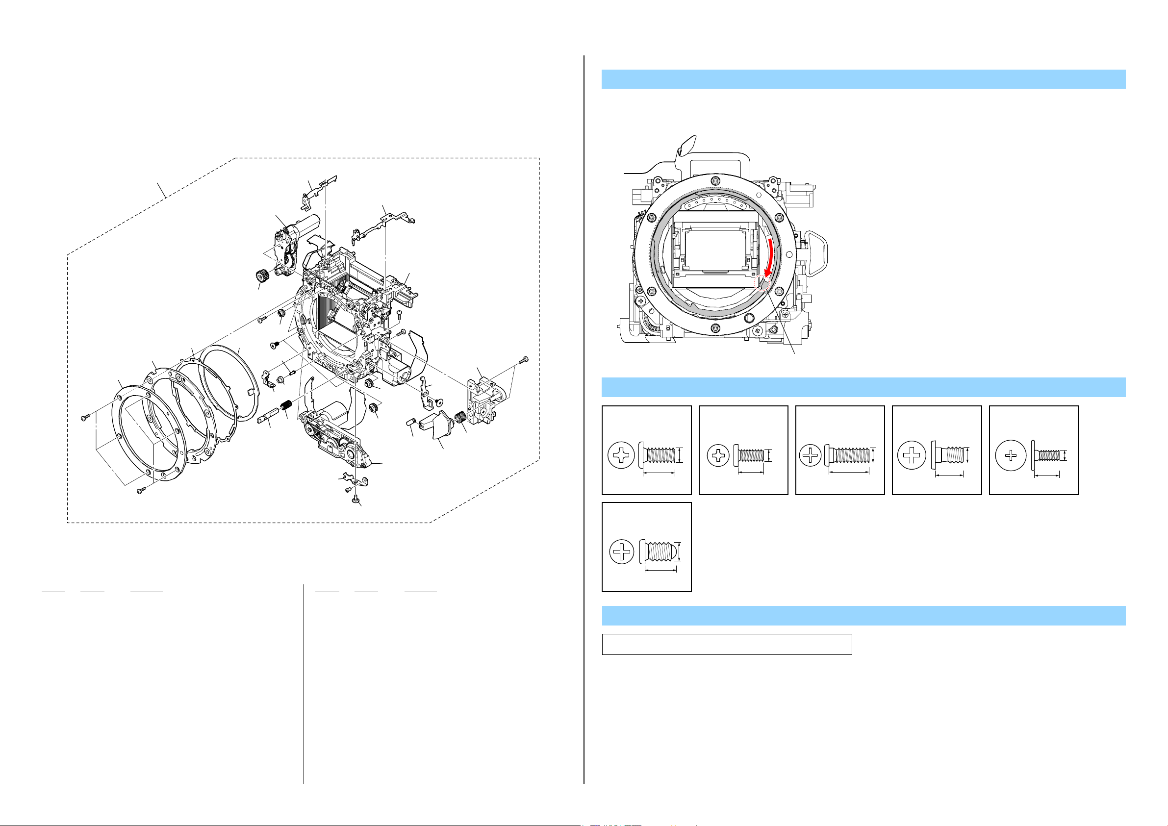
2-1-8. ANTI SHAKE UNIT SECTION
ns:notsupplied
Screw
#14: M1.7 X 2.5
(Silver)
2-599-475-11
#87: M1.6 X 5.3
(Black)
2-689-328-01
ns
352
352
352
ns
ns
#14
353 (Note4)
351
(Note1, 2)
354
1.7
2.5
1.6
5.3
Note
Note1: Referto“1-3.METHODFORCHECKINGTHEASSLIDER
UNIT(863)” on page 1-1 when checking the AS Slider Unit
Note3: Referto“1-5. METHODFORREPLACINGTHEAS SLIDER
(863).
BASSY”onpage1-2whenreplacingtheASSliderBAssy.
Note2: Referto“1-4.METHODFORADJUSTINGTHETEBURE
REVISE”onpage1-2whenadjustingtheTebureRevise.
Note4: Referto“1-6.METHODFORREPLACINGTHEASHOLDER
ACTUATORASSY” on p age 1-3 whe n r eplac in g theAS
HolderActuatorAssy.
Solder
356
Solder
#87
ns
ns
A
ns
ns
B
ns
354
#14
355
(Note3)
354
354
354
ns
B
A
Ref. No. Part No. Description Ref. No. Part No. Description
351 A-1782-917-A SLIDER UNIT (863 SERVICE), AS (Note1, 2)
352 4-110-892-01 SPRING, ADJUSTMENT AO
353 X-2548-677-1 AS HOLDER ACTUATOR ASSY (Note4)
354 2-695-356-11 BALL, BEARING
355 X-2548-676-1 AS SLIDER B ASSY (Note3)
* 356 4-256-515-01 HALL FPC PROTECTION SHEET
#14 2-599-475-11 SCREW (M1.7)
#87 2-689-328-01 SCREW, CCD BLAST ADJUSTMENT
DSLR-A560/A560L/A560Y/A580/A580L/A580Y/A580J_L2
2-10
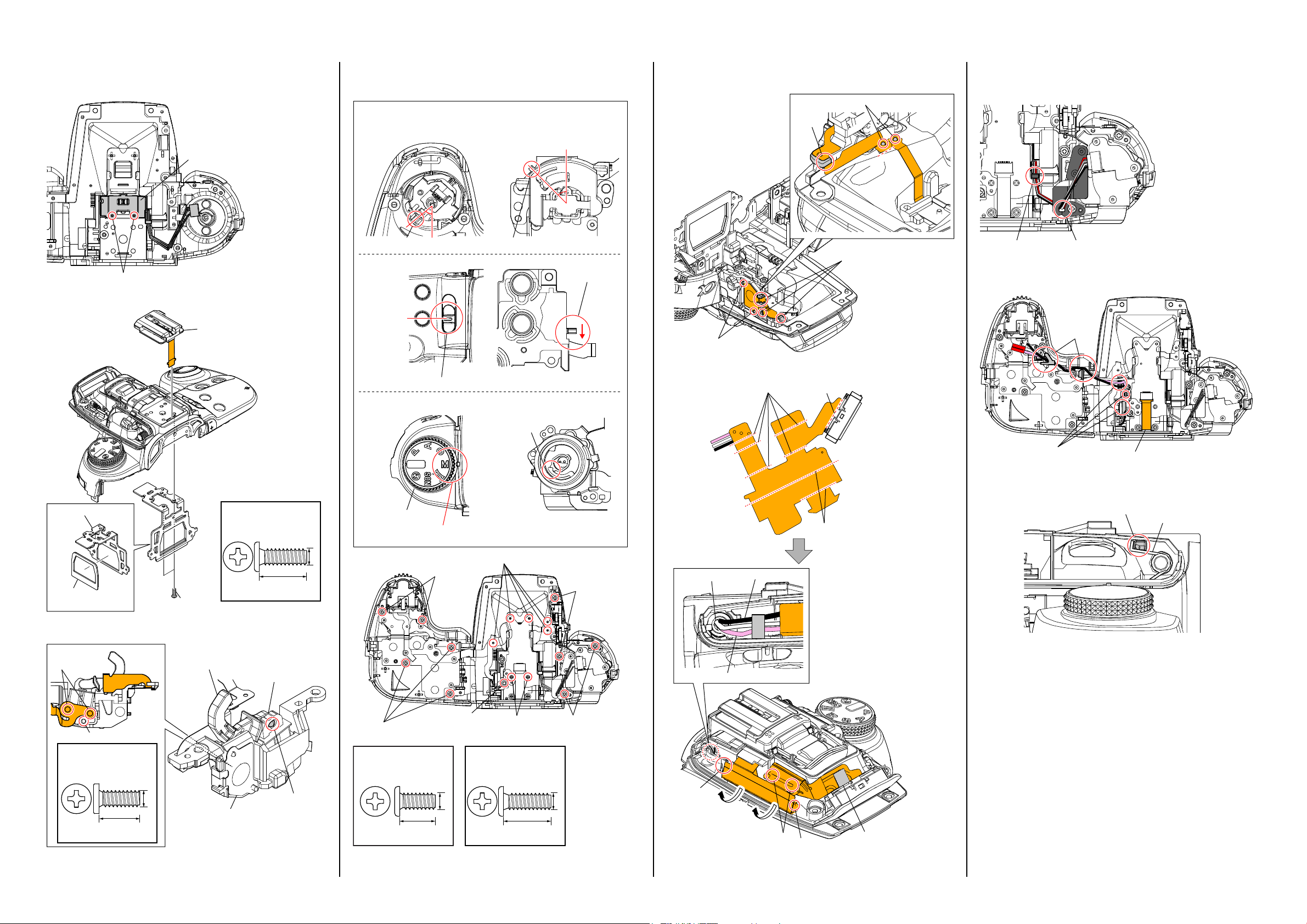
2-1-9. REMOTE HOLDER SECTION
DISASSEMBLY
1. Remove to numerical order (qd to qf) in the left figure.
2. The meaning of the sign in left figure is as follows. Be careful when it removes.
u-X: Flexible Board, Flat Cable, Harness
qd #8 X 1 → #12 X 1
Top View Right View
#12
qf Battery Holder Section
(See page 2-12)
u-14
u-14
u-14
401
AF Module Section
(See page 2-13)
#8
#12
qd�402
SP901 (Note)
404
#8
qf #12 X 1
Left View
Screw
#8: M1.7 X 3.5 (Tapping)
(Silver)
3-078-890-01
#12
#12: M1.7 X 5.0 (Tapping)
(Black)
3-080-204-21
#12
J9101
Ref. No. Part No. Description Ref. No. Part No. Description
401 X-2515-694-1 BD BATTERY CASE LID ASSY
402 X-2549-445-1 BD RT HOLDER ASSY
403 A-1797-668-A SMR-001 FLEXIBLE BOARD, COMPLETE (SERVICE)
(including J901 (Remote Holder)) (Note)
404 X-2549-875-1 BD SPEAKER SHEET METAL ASSY
405 3-076-631-01 CV PRV FLEXIBLE FIXED TAPE
J9101 1-691-737-42 JACK (SMALL TYPE)
SP901 1-858-462-11 LOUDSPEAKER (1.0CM) (Note)
#8 3-078-890-01 SCREW, TAPPING
#12 3-080-204-21 SCREW, TAPPING, P2
DSLR-A560/A560L/A560Y/A580/A580L/A580Y/A580J_L2
#12
403
(including J901 (Remote Holder))
(Note)
405
2-11
1.7
3.5
1.7
5.0
Note
Note: Referto“Assembly-4:SRM-001FlexibleBoard,Loudspeaker”
whenyouassemble.
2-1-10. BATTERY HOLDER SECTION
ns:notsupplied
Screw
#8: M1.7 X 3.5 (Tapping)
(Silver)
3-078-890-01
#91: M1.7 X 3.0 (Tapping)
(Silver)
2-695-434-11
457
462
461
458
(Note)
461
#8
#8
459
463
460
#91
#8
464
Claw
J902
(including battery terminal)
#8
465
Claw
ns
1.7
3.5
1.7
3.5
Note
Note: Refer to “Assembly-3: CV MCVedia Lid Spring” when you
assemble.
456
#8
452
455
454
#91
ns
451
453
C901
Ref. No. Part No. Description Ref. No. Part No. Description
451 4-154-720-01 BD CAPACITOR FIXED TAPE
452 A-1735-725-A ST-218 BOARD, COMPLETE
453 X-2549-448-1 BD BATTERY HOLDER ASSY
454 3-282-888-01 BD BATTERY LOCK CLAW
455 4-156-770-01 BD BT LOCK CLAW TENSION SP
461 4-154-702-01 BD GYRO CUSHION
462 1-489-243-11 GYJ-003 FLEXIBLE BOARD
* 463 4-154-700-01 BD EYELET (G)
* 464 4-154-701-01 BD GYRO BASE
465 X-2514-444-1 CV MEDIA BASE ASSY
456 1-880-444-11 STG-001 FLEXIBLE BOARD
457 4-154-727-21 CV MEDIA LID
* 458 4-154-730-01 CV MEDIA LID SPRING (Note)
* 459 4-154-729-01 CV MEDIA LID PLATE SPRING
* 460 4-154-728-01 CV MEDIA LID SHAFT
DSLR-A560/A560L/A560Y/A580/A580L/A580Y/A580J_L2
0* C901 1-114-603-11 ELECT 250uF 99% 330V
0 J902 1-822-838-11 DC JACK (including battery terminal)
#8 3-078-890-01 SCREW, TAPPING
#91 2-695-434-11 SCREW (T1.7), HEAD PAN TAPPING
2-12
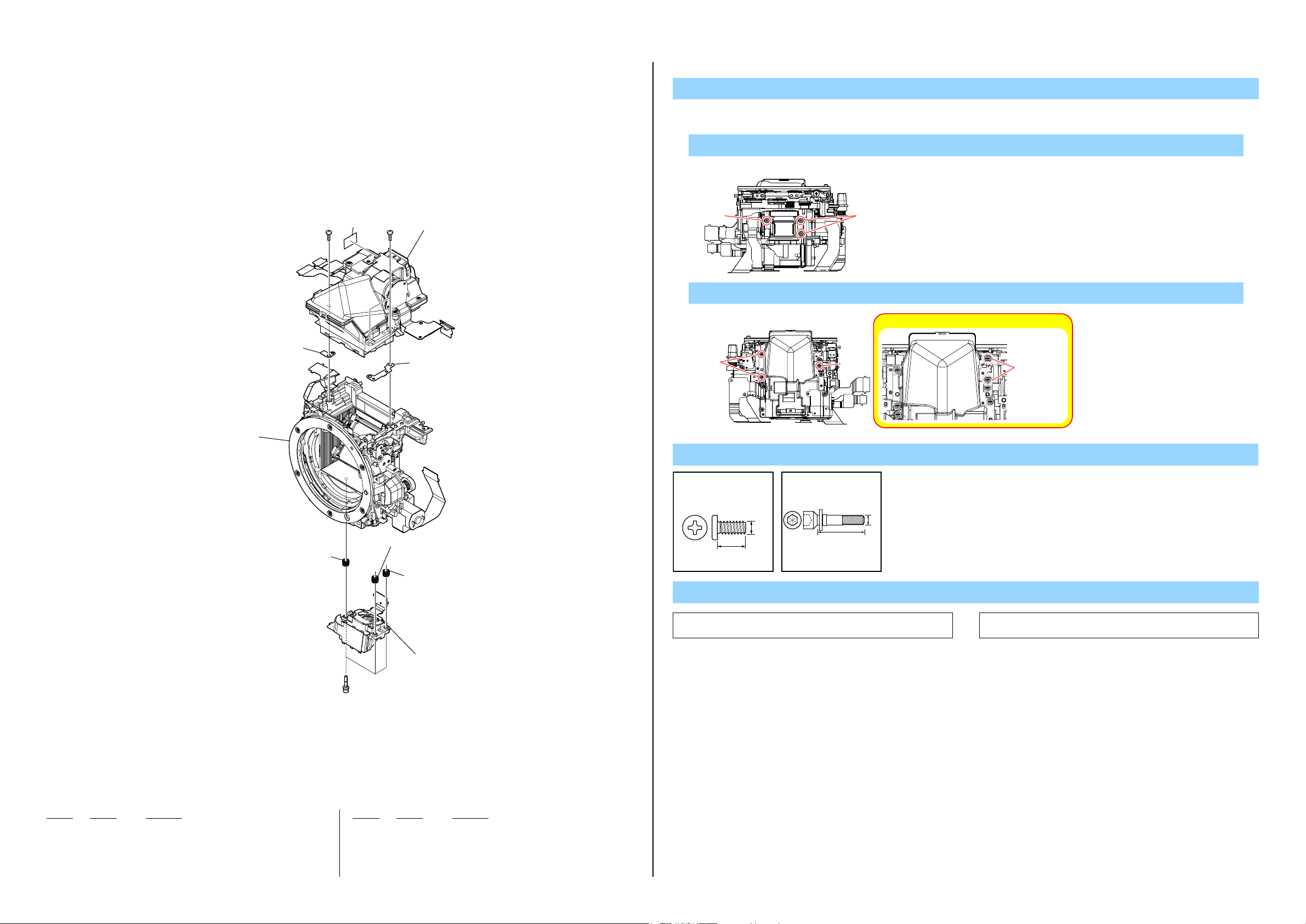
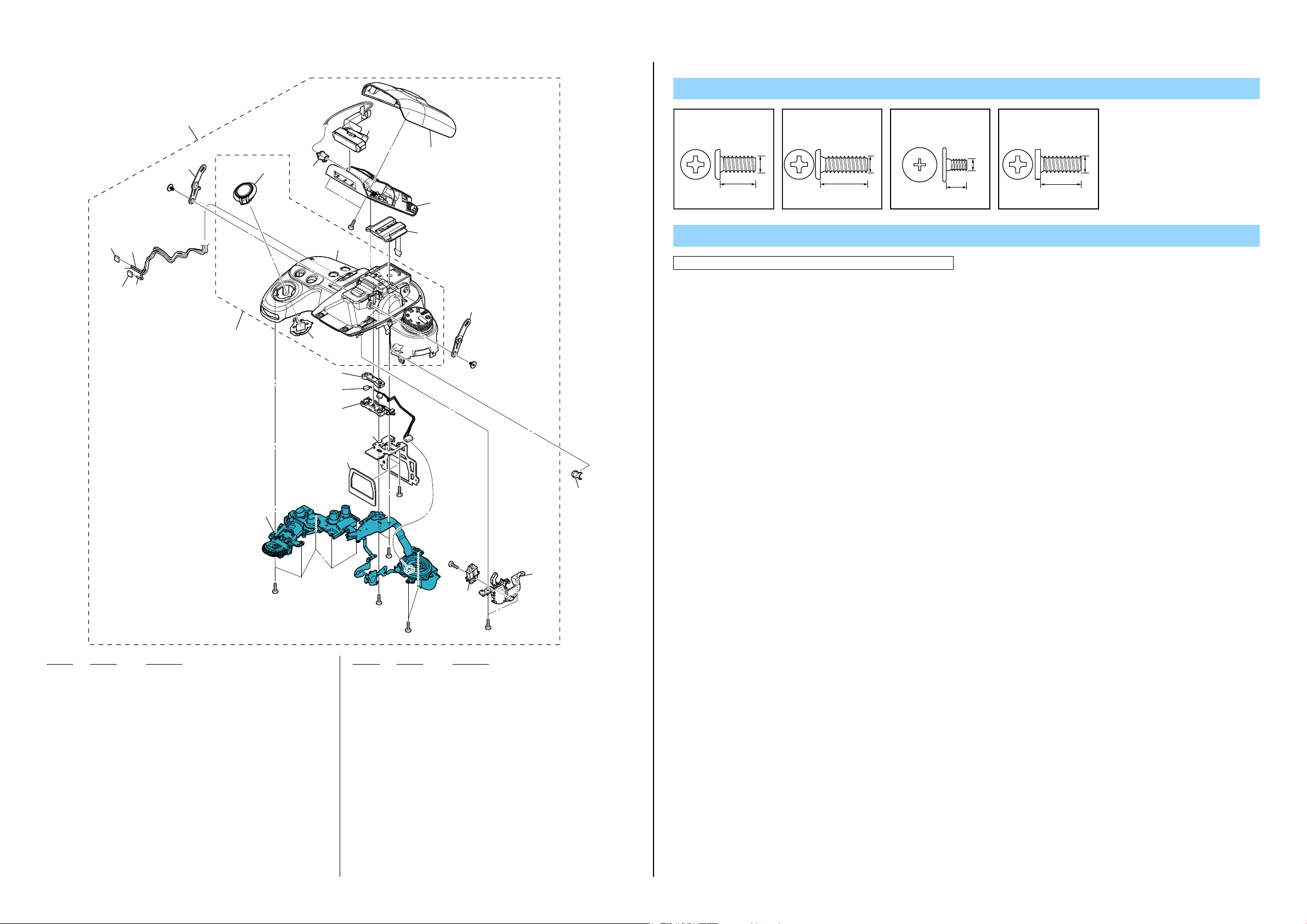
2-1-11. AF MODULE SECTION
DISASSEMBLY
1. Remove to numerical order (qg to qj) in the left figure.
qg #207 X 3 → S Adjustment SP (qg) X 3
Bottom View
qj Mirror Box Section (Sub Unit-1)
(See page 2-15)
503
qh-1
505
#64 #64
502
qg
qh�Mirror Box Section (Penta Unit)
(See page 2-14)
504
qh-2
502
qg
502
qg
#207
#207
qh #64 X 3 → VB Spacer (L) (qh-1) → VB Spacer (R) (qh-2)
#64
Top View
#64
Caution: Never touch two screws.
Screw
#64: M1.7 X 5.0 (Tapping)
(Silver)
2-666-551-21
5.0
1.7
#207: M1.6 X 8.0
(Silver)
4-191-605-01
1.6
8.0
Note
Don't touch
qg 501
(including AF-132 flexible board)
(Note1, 2)
#207
Ref. No. Part No. Description Ref. No. Part No. Description
501 A-1786-064-A ALX-8650 (including AF-132 flexible board) (Note1, 2)
502 2-693-420-01 SP, S ADJUSTMENT
503 4-141-111-31 VB SPACER (L)
504 4-141-110-31 VB SPACER (R)
* 505 4-154-698-01 EM ST SHIELD SHEET
DSLR-A560/A560L/A560Y/A580/A580L/A580Y/A580J_L2
#64 2-666-551-21 SCREW, TAPPING, P2
#207 4-191-605-01 S ADJUSTMENT SCREW
2-13
Note1: Refer to “Assembly-2: ALX-8650 (AF Module)” when you
assemble.
Note2: Refe r to “Assem bly-1 0: SAd justmen t Screw” wh en you
assemble.
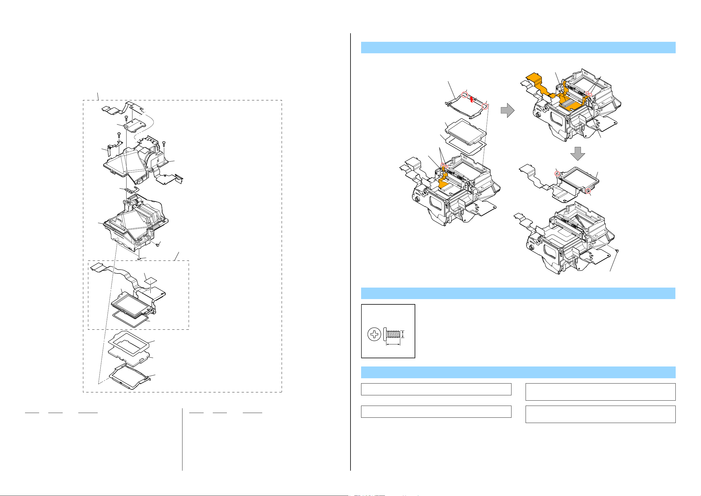
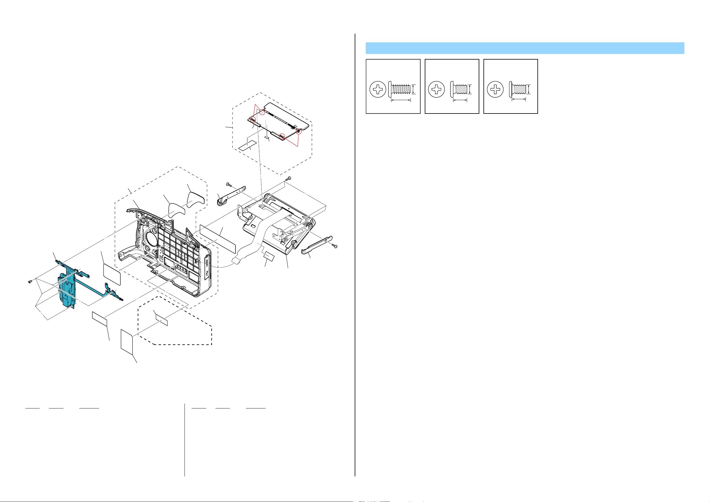
2-1-12. MIRROR BOX SECTION (PENTA UNIT)
ns:notsupplied
551
(including AE-036 flexible board, LCD903 (finder LCD),
IFL-004 flexible board and VTN-003 flexible board) (Note3)
DISASSEMBLY
VM OSD Unit Removal
1 Remove two claws pushing part A
below, and remove the VM FS Retainer
in the direction of arrow.
Claw
A
Claw
6 Adhesive Tape
8 Two Claws
ns
ns
ns
#76
ns
#76
ns
#76
ns
554
552
(including LCD902 (SI LCD), SIL-002 flexible board
and SI-067 flexible board)
553
555 (CAUTION)
(Size: 8.5mm X 12.2mm)
4 Adhesive Tape
Screw
2 Focus Plate
3 VB Spacer
5 Two Claws
0 Pin
7 Adhesive Tape
qs VM OSD Unit
qa Pin
9 OSD Holder VM Pin (L)
556
557 - 560
(Note2)
561
(Note1)
562
Ref. No. Part No. Description Ref. No. Part No. Description
551 A-1788-809-A VM PENTA UNIT 865S (including AE-036 flexible board,
LCD903 (finder LCD), IFL-004 flexible board and VTN-003 flexible board) (Note3)
552 4-152-739-01 VM PIN (L), OSD HOLDER
553 4-144-439-01 MB MAIN MIRROR CUSHION
554 A-1788-810-A VM OSD UNT 865S
(including LCD902 (SI LCD), SIL-002 flexible board and SI-067 flexible board)
555 CAUTION TAPE, VM SIL FPC DOUBLE STICK
556 4-152-743-01 VM OSD HOLDER CUSHION
557 4-152-746-01 VM SPACER, VB (T= 0.20 mm) (Note2)
558 4-152-746-11 VM SPACER, VB (T= 0.15 mm) (Note2)
559 4-152-746-21 VM SPACER, VB (T= 0.10 mm) (Note2)
560 4-152-746-31 VM SPACER, VB (T= 0.05 mm) (Note2)
561 A-1743-821-A VO FOCUSING SCREEN (SERVICE) (Note1)
562 4-152-745-01 VM FS RETAINER
#76 2-666-551-11 SCREW, TAPPING, P2
DSLR-A560/A560L/A560Y/A580/A580L/A580Y/A580J_L2
2-14
#76: M1.7 X 4.0 (Tapping)
(Silver)
2-666-551-11
1.7
4.0
Note
Note1: Refertopage1-1“1-1.METHODOFREPLACINGTHEFOCUS
Note3: Refertopage3-8“3-3.CLEANINGPROCEDUREOFVIEW-
PLATE”whenthefocusplateisreplaced.
FINDER”formethodofcleaningtheviewfinder.
Note2: Theseare spacers useto adjust thickness when Viewfinder
BackAdjustmentisdone.
AdjustingItem:“ViewfinderBackAdj.”
Caution:
Forthepartof555,cutSHEET,ADHESIVE(2-649-300-01)intothe
desiredlengthanduseit.
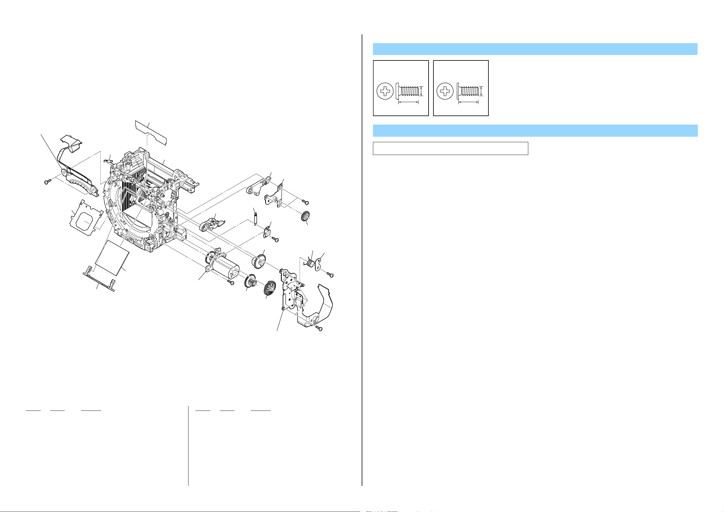
2-1-13. MIRROR BOX SECTION (SUB UNIT-1)
DISASSEMBLY
Iris Ring Removal
Rotate the Iris Ring clockwise, and remove it at the stop position (iris-in end).
At this time, do not rotate the Iris Joint Gear of the Aperture Unit.
#163
602
601 (Note)
603
#163
613
(including M902 (aperture motor)
and AP-033 flexible board)
612
#64
611
#164
604
605
610
609
608
607
606
614
623
#166
615
Mirror Box Section (Sub Unit-2)
(See page 2-16)
#23
#23
621
621
619
622
(including M901 (AF motor)
and AFP-005 flexible board)
624
620
618
#165
616
617
#23
Screw
#23: M1.7 X 4.0 (Tapping)
(Black)
3-080-204-11
4.0
#166: M1.7 X 3.0 (Tapping)
(Silver)
3-271-395-11
#64: M1.7 X 5.0 (Tapping)
(Silver)
2-666-551-21
1.7
5.0
Iris Ring Lever
#163: M2.0 X 5.5 (Tapping)
1.7
(Silver)
2-695-575-11
5.5
2.0
#164: M2.0 X 3.9
(Black)
3-268-954-11
3.9
#165: M1.7 X 3.0 (Tapping)
2.0
(Silver)
2-695-434-31
3.0
1.7
Ref. No. Part No. Description Ref. No. Part No. Description
601 A-1788-092-A MB MIRROR BOX SUB UNIT (Note)
602 2-689-021-01 MB H MOUNT
603 4-141-109-01 MB MOUNT SPACER
604 2-689-198-01 MB RING SP
605 4-141-393-01 AP IRIS RING
606 4-141-108-01 AF COUPLER
* 607 4-141-103-01 AF COUPLER TENSION SP
* 608 4-141-104-01 EM A MOUNT LUG PLATE (LOWER)
609 3-277-916-01 AP RING ROLLER C
610 3-268-951-01 SHAFT, RING ROLLER (C) (SV)
611 2-689-314-01 ROLLER B (SV), RING
612 2-689-306-01 GEAR, IRIS JOINT
613 A-1709-450-A AP APERTURE UNIT
(including M902 (aperture motor) and AP-033 flexible board)
* 614 4-141-102-02 EM A MOUNT LUG PLATE (UL)
* 615 4-141-101-02 EM A MOUNT LUG PLATE (UR)
616 A-1709-451-A MB LENS LOCK UNIT
* 617 4-141-090-01 MB LENS LOCK SP
* 618 4-141-091-01 MB LENS LOCK BUTTON
* 619 4-141-092-01 MB LENS LOCK PIN
620 4-141-105-01 MB COUPLER JOINT LEVER
621 2-689-313-01 ROLLER A (SV), RING
622 A-1709-449-A AF DRIVING UNIT
(including M901 (AF motor) and AFP-005 flexible board)
623 4-141-106-01 MB COUPLER LEVER
* 624 2-689-289-11 SHAFT, COUPLER LEVER
#23 3-080-204-11 SCREW, TAPPING, P2
#64 2-666-551-21 SCREW, TAPPING, P2
#163 2-695-575-11 SCREW (T2), +P1 PAN TAPPNG
#164 3-268-954-11 SCREW, AF BASE PLATE STOPPER
#165 2-695-434-31 SCREW (T1.7), HEAD PAN TAPPING
#166 3-271-395-11 SCREW (M1.7), LEVER ADJUSTMENT
DSLR-A560/A560L/A560Y/A580/A580L/A580Y/A580J_L2
1.7
3.0
Note
Note: Referto“Assembly-1:MirrorBoxSubUnit”whenyou
assemble.
2-15
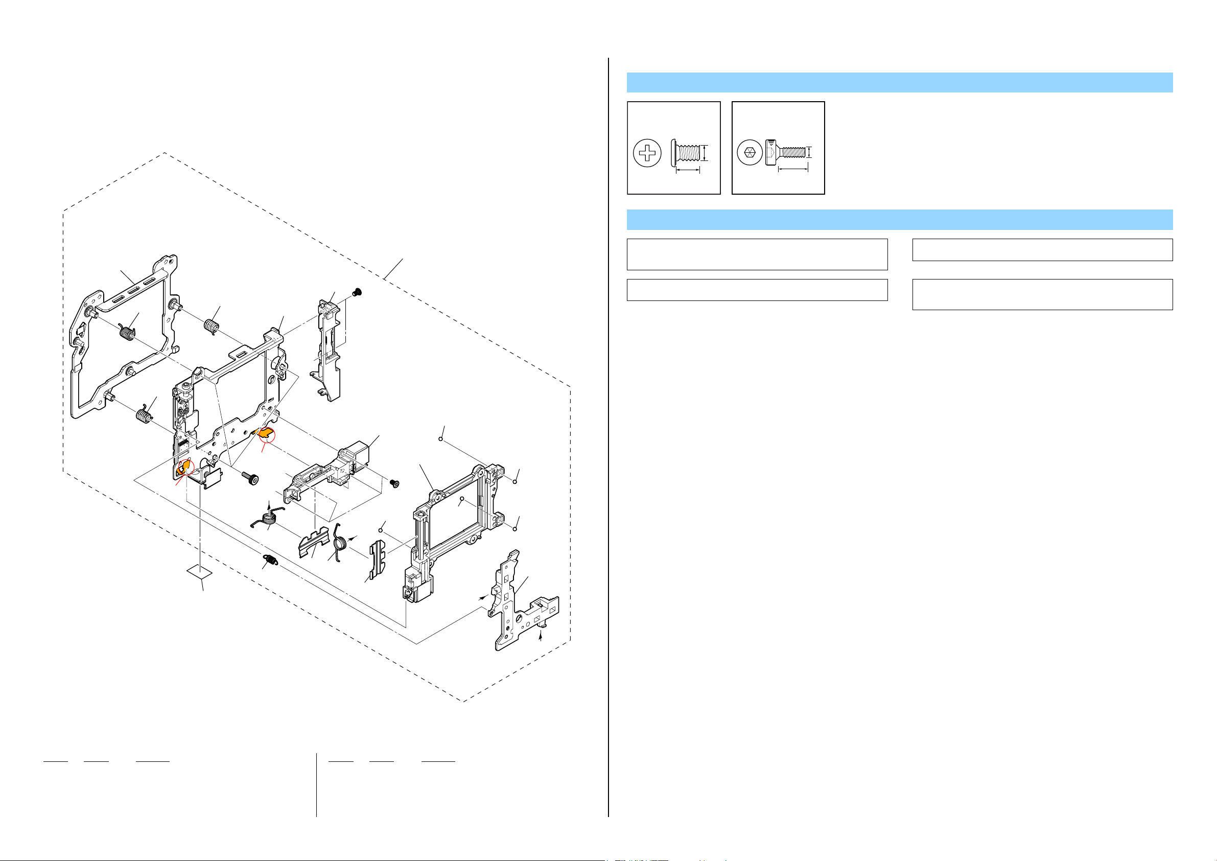
2-1-14. MIRROR BOX SECTION (SUB UNIT-2)
ns:notsupplied
Screw
#23: M1.7 X 4.0 (Tapping)
(Black)
3-080-204-11
#93: M1.7 X 3.5 (Tapping)
(Silver)
3-254-082-01
654
(including BL-034 flexible board)
#23
653
655
656
ns
657
658
661
659
660
ns
#23
ns
#93
662
663
1.7
4.0
1.7
3.5
Note
Note: Referto“Assembly-6:SLK-006FlexibleBoard”whenyou
assemble.
652
651
Ref. No. Part No. Description
651 3-279-657-11 RETAINER, MAIN MIRROR
652 4-141-080-01 MB MAIN MIRROR
653 4-207-870-01 MB AF MASK PLATE
654 A-1734-156-A MB BL CONTACT HOLDER UNIT857
(including BL-034 flexible board)
655 3-268-935-01 SP, SUB MIRROR FUNCTION
* 656 3-279-649-11 SHEET, BL DUST PROTECT
657 X-2348-731-1 MB MIRROR CHARGE LEVER ASSY
658 3-268-931-01 SP, SHUTTER CHARGE LEVER
659 4-207-867-01 MB SHUTTER CHARGE LEVER
660 3-268-937-01 RETAINER, ADJUSTMENT PLATE
DSLR-A560/A560L/A560Y/A580/A580L/A580Y/A580J_L2
665
(including M903
(charge motor))
#23
ns
ns
664
(including SLK-006 flexible board)
(Note)
Ref. No. Part No. Description
661 4-207-868-01 MB MIRROR CHARGE CAM GEAR
662 3-268-929-01 DRIVING (SP), MIRROR (SV)
663 3-268-930-01 RETAINER, MIRROR DRIVING (SP)
664 X-2514-252-1 MB CHARGE BASE PLATE B ASSY
(including SLK-006 flexible board) (Note)
665 A-1734-155-A MB CHARGE BASE PLATE A UNIT
(including M903 (charge motor))
#23 3-080-204-11 SCREW, TAPPING, P2
#93 3-254-082-01 SCREW
#93
#93
2-16
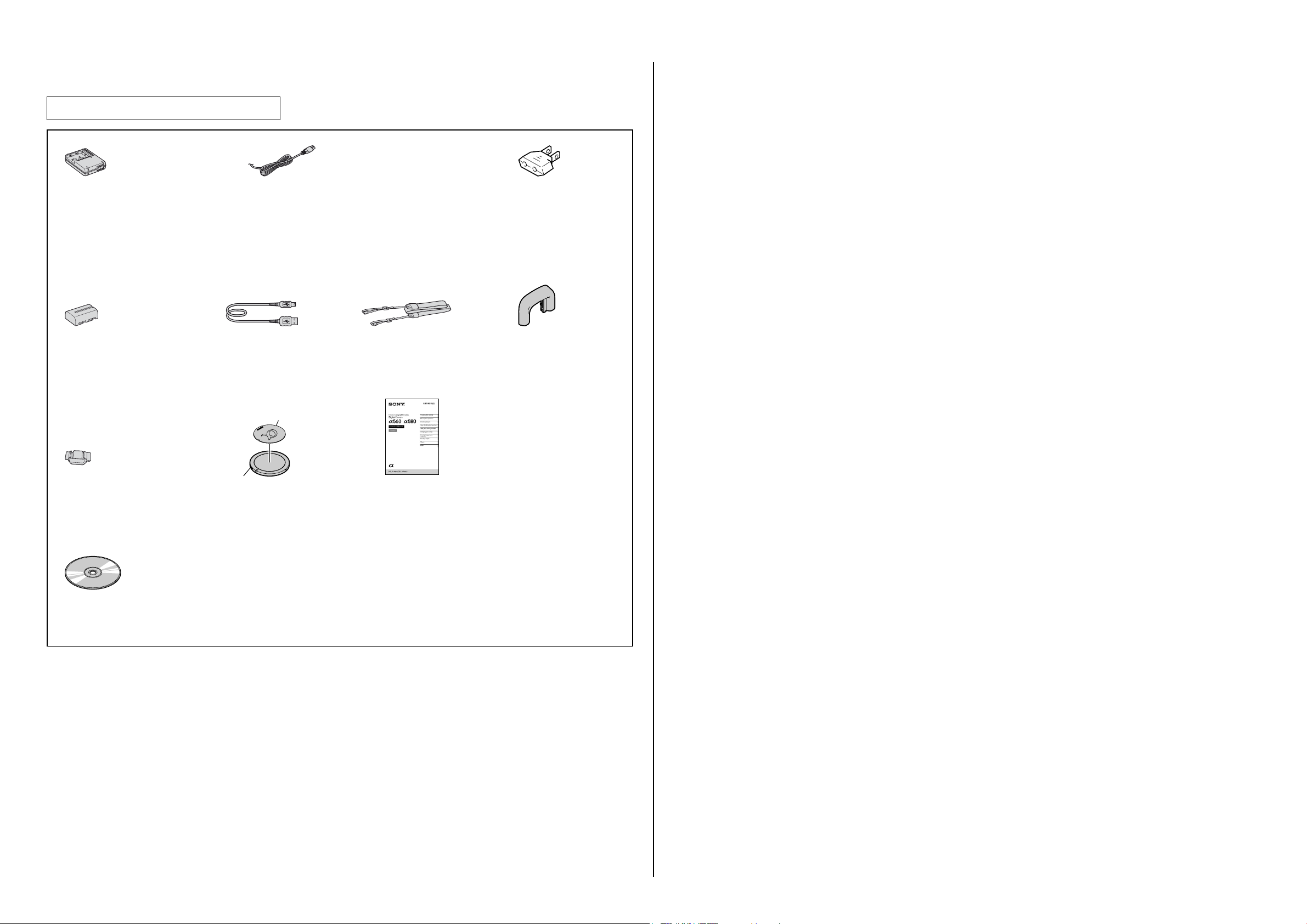
Checking supplied accessories.
Note: Thisitemissuppliedwiththeunitasan
accessory,butisnotpreparedasaservicepart.
Battery charger
(BC-VM10)
0 1-479-742-41 (EXCEPT US)
0 1-479-742-51 (US)
Rechargeable battery pack
(NP-FM500H)
(Note)
Eyepiece cover
3-273-458-01
CD-ROM
- Application Software for α camera
4-195-615-02
Power cord (mains lead)
0 1-790-107-42 (US)
0 1-832-121-51 (CH)
0 1-837-421-11 (UK, E (Saudi, Hong Kong))
0 1-837-427-11 (AEP, E (EXCEPT Saudi, Hong Kong))
0 1-837-428-11 (KR)
0 1-837-429-11 (AUS)
USB cable
1-829-868-31
Body Cap Seal
2-894-387-01
Body Cap
3-282-743-01
Shoulder strap
4-145-436-01
Instruction Manual
• (Only for destination Japanese model)
英語,韓国語,中国語のみ部品供給可能です。
4-207-863-11 (ENGLISH)
∗ 4-207-863-21 (FRENCH, ITALIAN)
∗ 4-207-863-31 (SPANISH, PORTUGUESE)
∗ 4-207-863-41 (GERMAN, DUTCH)
∗ 4-207-863-51 (TRADITIONAL CHINESE,
∗ 4-207-863-61 (RUSSIAN)
∗ 4-207-863-71 (ARABIC, PERSIAN)
4-207-863-81 (KOREAN)
4-207-863-91 (SIMPLIFIED CHINESE) (CH)
∗ 4-209-041-11 (POLISH)
Conversion (2P) Adaptor
0 1-569-008-12
Eyecup
X-2514-442-1
SIMPLIFIED CHINESE) (E)
DSLR-A560/A560L/A560Y/A580/A580L/A580Y/A580J_L2
2-17E
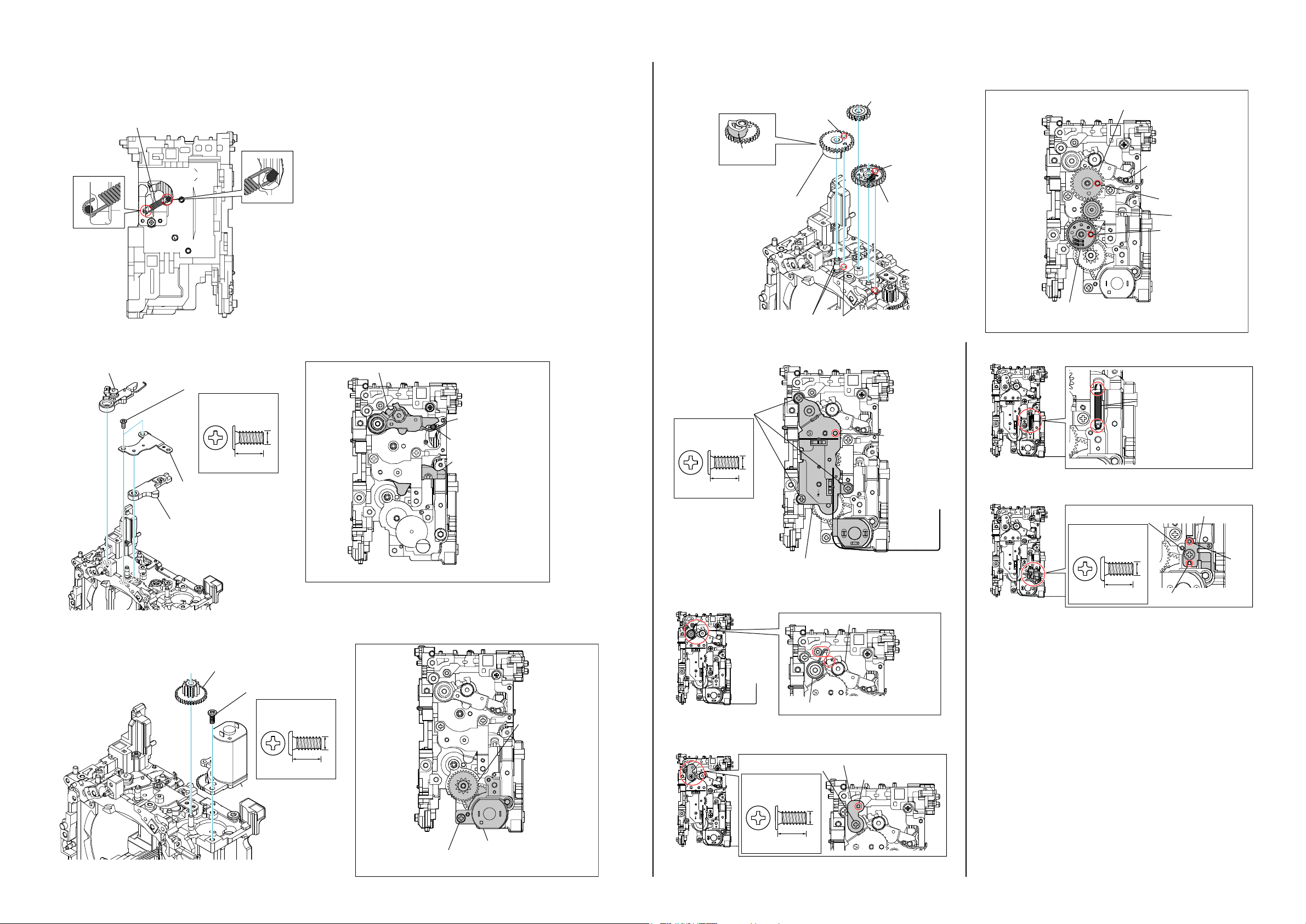
3-1. ASSEMBLY
1-3. Charge Base Plate A Unit, Deceleration Gear 2
Assembly-1: Mirror Box Sub Unit
1-1. Sub Mirror Function Spring
Sub Mirror Function Spring
∗ Note the direction.
3. ASSEMBLY
1-4. Shutter Cam Gear Assy, Idle Gear, Mirror Charge Cam Gear
Hole
2 Idle Gear
- Gears Position -
Mirror Charge Cam Gear
- Left View -
1-2. Mirror Charge Lever Assy, Shutter Charge Lever
1 Mirror Charge Lever Assy
4 Screw
#93: M1.7 X 3.5 (Tapping)
(Silver)
3-254-082-01
3.5
3 Charge Base Plate C Assy
2 Shutter Charge Lever
G G-85
3 Mirror Charge Cam Gear
Hole
1 Shutter Cam Gear Assy
Main Mirror Holder Down
Hole
Idle Gear
Hole
Shutter Cam Gear Assy
G G-85
1-5. Charge Base Plate B Assy
Hole
- Right View -
1-8. Shutter Charge Lever Spring
Mirror Charge Lever Assy
Shutter Charge Lever Spring
∗ Note the direction.
(Silver)
3-254-082-01
3.5
Screw
Hole
1.7
- Right View -
Spring
1.7
Main Mirror Holder Boss
#93: M1.7 X 3.5 (Tapping)
Shutter Charge Lever
1-9. Adjustment Plate Retainer
Adjustment Plate Retainer
4.0
Screw
1.7
Boss
Boss
- Right View -
1-6. Mirror Driving Spring
Charge Base Plate B Assy
- Right View -
- Right View -
#23: M1.7 X 4.0 (Tapping)
(Black)
3-080-204-11
Mirror Charge Lever Assy
DSLR-A560/A560L/A560Y/A580/A580L/A580Y/A580J_L2
3 Deceleration Gear 2
2 Screw
#23: M1.7 X 4.0 (Tapping)
(Black)
3-080-204-11
1 Charge Base Plate A Unit
Deceleration Gear 2
1.7
4.0
- Right View -
1-7. Mirror Driving (SP) Retainer
#93: M1.7 X 3.5 (Tapping)
Mirror Driving Spring
Screw
(Silver)
3-254-082-01
1.7
3.5
Mirror Driving (SP) Retainer
Boss
Charge Base Plate A Unit
Screw (#23)
- Right View -
- Right View -
3-1
1-10. BL Contact Holder Unit, BL Dust Protect Sheet
BL Dust Protect Sheet
- Back View -
Screw
#23: M1.7 X 4.0 (Tapping)
(Black)
3-080-204-11
1-13. Iris Joint Gear, Aperture Unit
∗ The Aperture Unit is supplied by being set in the charge position
(initial position), but if this position is disordered when the Aperture
Unit is removed, or if the charge position is to be set again, perform
as follows.
∗ Refer to "1-14. The Aperture Unit Charge Position Setting" for
the confirm method at the charge position.
3 Screw
#64: M1.7 X 5.0 (Tapping)
(Silver)
2-666-551-21
1.7
5.0
1-15. The Aperture Unit Free Position Setting
∗ Set the Aperture Unit to a free position once, if the gear was rotated
accidentally and the charge position is disordered, or if the charge
position was shifted during disassembly.
Gear rotating
direction to set
the charge position
Gear rotating
direction to make
the unit free
1-16. A Mount Lug Plate (UR)
Boss
Boss
Claw
Claw
Boss
- Front View -
1-11. AF Driving Unit
#164: M2.0 X 3.9
Screw
- Front View -
(Black)
3-268-954-11
1.7
4.0
- Front View -
In a free state, the edge of this spring
will move up and down about 1 mm if
the gear is moved a little.
1-17. A Mount Lug Plate (UL)
Boss
2 Aperture Unit
Claw
In a free state, a hole in the gear almost
coincides with a hole in the Aperture Unit.
2.0
3.9
1 Iris Joint Gear
Claw
Boss
1-18. AF Coupler, AF Coupler Tension Spring
Boss
AF Coupler
Soldering
Note: The spring is deformed and cannot
be used if the gear is rotated too
AF Coupler Tension Spring
∗ Note the direction.
much from a free state.
AF Driving Unit
1-12. A Mount Lug Plate (Lower)
Boss
Claw
A Mount Lug Plate (Lower)
DSLR-A560/A560L/A560Y/A580/A580L/A580Y/A580J_L2
AF Driving Unit Flexible
Board Arrangement
- Left View -
1-14. The Aperture Unit Charge Position Setting
1. Check that the Aperture Unit is in a free state.
2. After confirming that the Aperture Unit is in a free state, rotate the
gear by 3 turns.
3. After rotating the gear by 3 turns, set the Aperture Unit where the
holes in the gear and the Aperture Unit coincide. This position is the
charge position.
∗ Refer to "1-15. The Aperture Unit Free Position Setting" for
the setting and the confirm method at the free position.
3-2
First, check the
spring edge position.
If the edge of spring is located downward,
rotate the gear in the arrow direction to
search a free position.
∗ In a free position, the edge of spring is
located upward.
ALX-8650 Flexible Board
1-19. Coupler Lever
Claw
1-21. Ring Roller (A), Iris Ring
1. With the Aperture Unit set in the charge position (see "1-14.
The Aperture Unit Charge Position Setting" ), install it on
the front frame set.
∗ The Aperture Unit has been set in the charge position, if it is not
removed.
However, the iris ring must be in the removed state (where the Iris
Joint Gear is not rotated).
2. Install the Iris Ring with it's a punch mark aligned with a line that
connects the Iris Joint Gear shaft and the optical axis center.
Optical Axis Center
Ring Roller (A)
Ring Roller (A)
Iris Ring
1-24. Ring (SP), Mount Spacer, H Mount
Ring (SP)
Mount Spacer
Assembly-2: ALX-8650 (AF Module)
Rib
G G-85
Coupler Lever Shaft
1-20. Lens Lock Unit
#23: M1.7 X 4.0 (Tapping)
(Black)
3-080-204-11
Screw
4.0
Lens Lock Unit
- Right View -
Lever Adjustment Screw
#166: M1.7 X 3.0 (Tapping)
Claw
1.7
- Top View -
Soldering
(Silver)
3-271-395-11
3.0
Screw
#23: M1.7 X 4.0 (Tapping)
(Black)
3-080-204-11
Claw
Coupler Lever
1.7
4.0
- Back View -
H Mount
6
2
Assembly-3: CV Media Lid Spring
1
CV Media Lid Spring
Iris Joint Gear Shaft
1-22. Ring Roller (B), Ring Roller (C), Ring Roller (C) Shaft
Ring Roller (B)
Ring Roller (C)
1.7
Ring Roller (C) Shaft
Ring Roller (C)
G G-85
Ring Roller (C) Shaft
Ring Roller (C)
Iris Ring
Ring Roller (C) Shaft
1-23. Lens Lock Button, Lens Lock
Punch Mark
Ring Roller (B)
Iris Ring
- Front View -
Pin, Lens Lock Spring
Lens Lock Pin
- Front View -
4
3
∗ Tighten six screws in order of the number.
#163: M2.0 X 5.5 (Tapping)
(Silver)
2-695-575-11
2.0
5.5
1-25. Coupler Joint Lever
5
Rib
DSLR-A560/A560L/A560Y/A580/A580L/A580Y/A580J_L2
Lens Lock Spring
Lens Lock Button
3-3
Coupler Joint Lever
Screw
#165: M1.7 X 3.0 (Tapping)
(Silver)
2-695-434-31
3.0
1.7
Assembly-4: SMR-001 Flexible Board, Loudspeaker
Claw
Boss
Boss
SMR-001 Flexible Board
Assembly-5: Shutter Unit (AFE-3032)
Mirror
DC Power Supply
(2V, 1A)
Assembly-6: SLK-006 Flexible Board
Claw
7-2. ST Strobe Guide Arm Assy (L/R)
ST Strobe Guide Arm Assy (R)
Open
Match shape.
Boss
Loudspeaker
Rib
Supply the power (2V, 1A) to the charge motor to rotate
it forward so as to move up the mirror completely.
Boss
Boss
Shutter Unit (AFE-3032)
Push the surplus part of the flexible board in.
Rib
Assembly-7: Top Cover Block
7-1. ST Strobe Base Cover Assy
ST Strobe Base Cover Assy
Do not bend the spring.
Shaft
CV Top Cover Assy
Install ST Strobe Guide Arm Assy (L) similarly.
Screw
#91: M1.7 X 3.0 (Tapping)
(Silver)
2-695-434-
1.7
3.5
7-3. ST Strobe Hinge Collar
Shaft
Rotate it by 180°.
Screw
Do not open the space.
DSLR-A560/A560L/A560Y/A580/A580L/A580Y/A580J_L2
ST Strobe Hinge Collar
Rib
3-4
7-4. Microphone Assy.
Microphone Assy
7-7. Control Switch Block (TK86500)
Confirm the position of each part.
CV Top Cover Assy Side
Power Knob
Control Switch Block Side
7-8. Control Switch Block (TK86500) Flexible Board
Boss
Claw
7-10. Microphone Unit Harness
Boss
7-5. Shoe Connector.
BD Eye Piece Frame
Shoe Connector
#12: M1.7 X 5.0 (Tapping)
(Black)
3-080-204-21
Power Knob
LV Knob
“LIVE VIEW”
Side
Mode Dial
Mode Dial
45°
Power Lever
LV Knob
Make "M" the horizontal.
Hook
45°
Slide Lever
Boss
7-9. Flash Unit (FL85700)
Valley fold
HookRib
Claw
7-11. Flash Unit (FL85700) Harness / Shoe Connector Flexible Board
Rib
Valley fold
Rib
Shoe Connector Flexible Board
7-12. Pop Up Spring
Rib
Pop Up Spring
Valley fold
BD Eye Piece
Dust Cushion (865)
7-6. Plunger Solenoid
Solder
Screw
#172: M1.4 X 4.0 (Tapping)
(Black)
2-178-410-01
4.0
Screw
ST Stroboscope Lock Assy
1.4
Control Switch Block (TK86500)
5.0
Plunger Solenoid
Boss
1.7
Screw (#8)
Screw (#8)
#8: M1.7 X 3.5 (Tapping)
(Silver)
3-078-890-01
3.5
Screw (#8)
#12: M1.7 X 5.0 (Tapping)
1.7
Boss
Screw (#12)
(Black)
3-080-204-21
5.0
Screw (#8)
Screw (#8)
1.7
Rib
White
Pink
Black
Claw
Boss
Adhesive Tape
DSLR-A560/A560L/A560Y/A580/A580L/A580Y/A580J_L2
3-5
7-13. ST Strobe Cover
ST Strobe Cover
7-14. Connector Housing 2P
Connector Housing 2P
(Red)
Ditch
Connector Housing 2P
(White)
Assembly-10: S Adjustment Screw
S Adjustment Screw
Pink
White
Black
Ditch
Claw
Claw
Claw
Assembly-8: Top Cover Block Assy
LV Knob
Confirm the position of the
LIVE VIEW/OVF switch.
B B-50
S Adjustment Screw
Assembly-11: Note on attachment of the SMR-001 and
the SLK-006 Flexible Board
When attach the SME-001 Flexible Board and the SLK-006 Flexible
Board to the AM-025 Board, attach the SMR-001 Flexible Board firstly
to make the SLK-006 Flexible Board outside of it.
AM-025 Board
1 SMR-001 Flexible Board
2 SLK-006 Flexible Board
Screw
#12: M1.7 X 5.0 (Tapping)
(Black)
3-080-204-21
1.7
5.0
DSLR-A560/A560L/A560Y/A580/A580L/A580Y/A580J_L2
Assembly-9: Flash Unit (FL85700) Harness
Rib
Assembly-12: Assemble the CV FRONT COVER ASSY
When assembling the CV Front Cover Assy, check if
the Focus Mode Switch of both the CV Front Cover Assy and
the MB AF MF Change Lever are in AF position.
CV Front Cover Assy
Focus Mode Switch
MB AF MF Change Lever
3-6
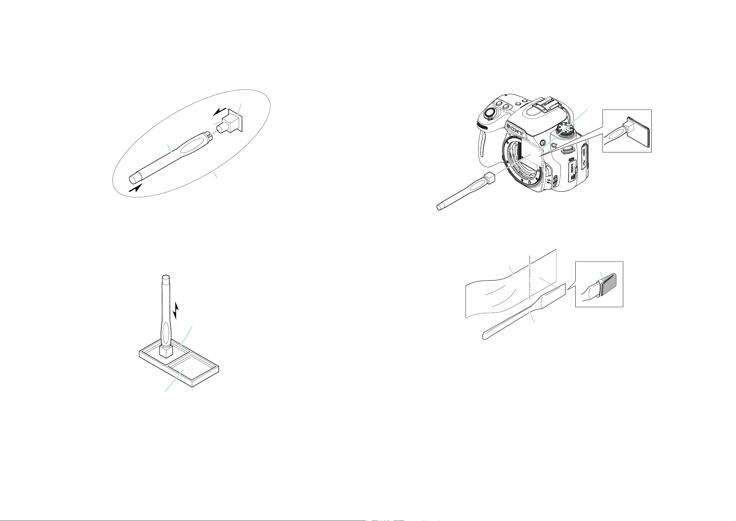
3-2. CLEANING PROCEDURE OF OLPF
<Preparation for Remedy>
If you use the new Jig (J-6082-663-A) below, make sure to clean the CCD Cleaning Jig (Tip) below before using, please.
Note: Protection sheet is for preventing the scratch of a surface on the Jig (Tip).
The protection sheet may be come off the Jig when you take the Jig from a bag, but it is no problem.
Protection Sheet
CCD Cleaning Jig (Tip)
CCD Cleaning Jig
CCD Cleaning Jig (New)
(J-6082-663-A)
<Cleaning Procedure for Tip of CCD Cleaning Jig>
1. Put the two cleaning cloths on a tray like below.
1 Souse the one cleaning cloth in ethyl alcohol.
2 Put the other cleaning cloth on a tray as it is dry.
2. Dab the tip of CCD cleaning jig at the cleaning cloth of 1 5 or 6 times.
* Do not slide the tip from right to left or up and down while dabbing.
3. Dab the tip of CCD cleaning jig at the cleaning cloth of 2 5 or 6 times.
* Do not slide from right to left or up and down while dabbing.
4. Wait until the tip will be dried completely.
<Cleaning Procedure for the OLPF>
1. Clean up the tip of CCD cleaning jig.
2. Set a camera to a cleaning mode.
3. Dab the tip of CCD cleaning jig at the OLPF, and pull up straight.
* Do not slide from right to left or up and down while dabbing.
4. Repeat “3” several times to clean up.
5. According to service manual, check if there is dirt on the CCD.
OLPF
<CAUTION>
If you cannot remove dirt with remedy above, cleaning by the following jig are used.
Soak a small amount of EE3310 (Liquid cleaner) after wrapping the cleaning cloth (J-6082-636-A) around the cleaning jig (J-6082-635-A).
Cut
Cleaning Cloth
(J-6082-636-A)
EE3310
2 The dry cleaning cloth.
DSLR-A560/A560L/A560Y/A580/A580L/A580Y/A580J_L2
1 Souse the cleaning
cloth in ethyl alcohol.
Cleaning Jig
(J-6082-635-A)
3-7
 Loading...